Embed Size (px)
Citation preview
IN600AV SYSTEM CONTROLLER
INSTALLATION AND OPERATION MANUAL

1. Save the carton and packing material even if the equipment has arrived in good condition. Should you ever need to ship the unit, use only the original factory packing.
2. Read all documentation before operating your equipment. Retain all documentation for future reference.
3. Follow all instructions printed on unit chassis for proper operation.
4. Do not spill water or other liquids into or on the unit, or operate the unit while standing in liquid.
5. Make sure power outlets conform to the power requirements listed on the back of the unit.
6. Do not use the unit if the electrical power cord is frayed or broken. The power supply cords should be routed so that they are not likely to be walked on or pinched by items placed upon or against them, paying particular attention to cords and plugs, convenience receptacles, and the point where they exit from the appliance.
7. Always operate the unit with the AC ground wire connected to the electrical system ground. Precautions should be taken so that the means of grounding of a piece of equipment is not defeated.
8. Mains voltage must be correct and the same as that printed on the rear of the unit. Damage caused by connection to improper AC voltage is not covered by any warranty.
9. Have gain controls on amplifi ers turned down during power-up to prevent speaker damage if there are high signal levels at the inputs.
10 Power down and disconnect units from mains voltage before making connections.
11. Never hold a power switch in the “ON” position if it won’t stay there itself!
12. Do not use the unit near stoves, heat registers, radiators, or other heat producing devices.
13. Do not block fan intake or exhaust ports. Do not operate equipment on a surface or in an environment which may impede the normal fl ow of air around the unit, such as a bed, rug, weathersheet, carpet, or completely enclosed rack. If the unit is used in an extremely dusty or smoky environment, the unit should be periodically “blown free” of foreign matter.
14. Do not remove the cover. Removing the cover will expose you to potentially dangerous voltages. There are no user serviceable parts inside.
15. Do not drive the inputs with a signal level greater than that required to drive equipment to full output.
16. Do not connect the inputs / outputs of amplifi ers or consoles to any other voltage source, such as a battery, mains source, or power supply, regardless of whether the amplifi er or console is turned on or off.
17. Do not run the output of any amplifi er channel back into another channel’s input. Do not parallel- or series-connect an amplifi er output with any other amplifi er output. Australian Monitor Inc is not responsible for damage to loudspeakers for any reason.
18. Do not ground any red (“hot”) terminal. Never connect a “hot” (red) output to ground or to another “hot” (red) output!
19. Non-use periods. The power cord of equipment should be unplugged from the outlet when left unused for a long period of time.
20. Service Information Equipment should be serviced by qualifi ed service personnel when:
A. The power supply cord or the plug has been damaged.
B. Objects have fallen, or liquid has been spilled into the equipment
C. The equipment has been exposed to rain
D. The equipment does not appear to operate normally, or exhibits a marked change in performance
E. The equipment has been dropped, or the enclosure damaged.
THIS SAFETY INFORMATION IS OF A GENERAL NATURE AND MAY BE SUPERSEDED BY INSTRUCTIONS CONTAINED WITHIN THIS MANUAL
IMPORTANT SAFETY INFORMATION
PAGE 3IN600 INSTALLATION AND OPERATION MANUAL
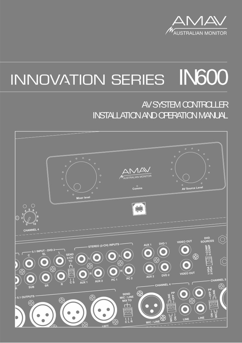
The Innovation series from AMAV is a huge step forward in the interfacing and management of audio and visual sources. Integrating a host of smart, high end features in a compact package that offers the end user extremely simple control over their complex audio visual system. The Innovation series is as ground breaking as it is simple to operate.
The IN600 takes the Innovations series concept to the next level in terms of fl exibility and complete system control. The IN600 features an on board mic/line mixer, 6 AV source inputs, and 6 balanced XLR outputs so it can be confi gured as a 5.1 front end. The IN600 also features RS232 for projector control and logic output for screen up/down control. With the IN600 we give the AV integrator the ability to use the IN600 for full room AV control or it can be interfaced with third party control systems if desired. The IN600 offers untold fl exibility for AV control in an extremely user friendly package.
AUS, EUR, USACopyright 21st Aug 2008
REV A 21st Aug 2008
This symbol is intended to alert the user to the presence of uninsulated “dangerous voltage” within the products enclosure that may be of suffi cient magnitude to constitute a risk of electric shock to persons.
This symbol is intended to alert the user to the presence of important operational and maintenance (servicing) instructions in the literature accompanying the appliance.
To prevent electric shock do not use this (polarised) plug with an extension cord, receptacle or other outlet unless the blades can be fully inserted to prevent blade exposure. To prevent electric shock, match wide blade of plug to wide slot, fully insert.
Caution:
CAUTION
CAUTION: TO REDUCE THE RISK OF ELECTRIC SHOCK,DO NOT REMOVE COVER (OR BACK),
NO USER SERVICEABLE PARTS INSIDE, REFER SERVICING TO QUALIFIED SERVICE PERSONAL.
WARNING!TO REDUCE THE RISK OF FIRE OR ELECTRIC SHOCKDO NOT EXPOSE THIS EQUIPMENT TO RAIN OR MOISTURE.
RISK OF ELECTRIC SHOCKDO NOT OPEN
INTRODUCTION AND CONTENTS
INTRODUCTION 3
FRONT PANEL 4
REAR PANEL 5
INSTALLATION 6
SETUP / SOFTWARE 7-9
INTERNAL ADJUSTMENTS 10
BLOCK DIAGRAM 11
DIMENSIONS 12
SPECIFICATIONS 13
PAGE 4 IN600 INSTALLATION AND OPERATION MANUAL
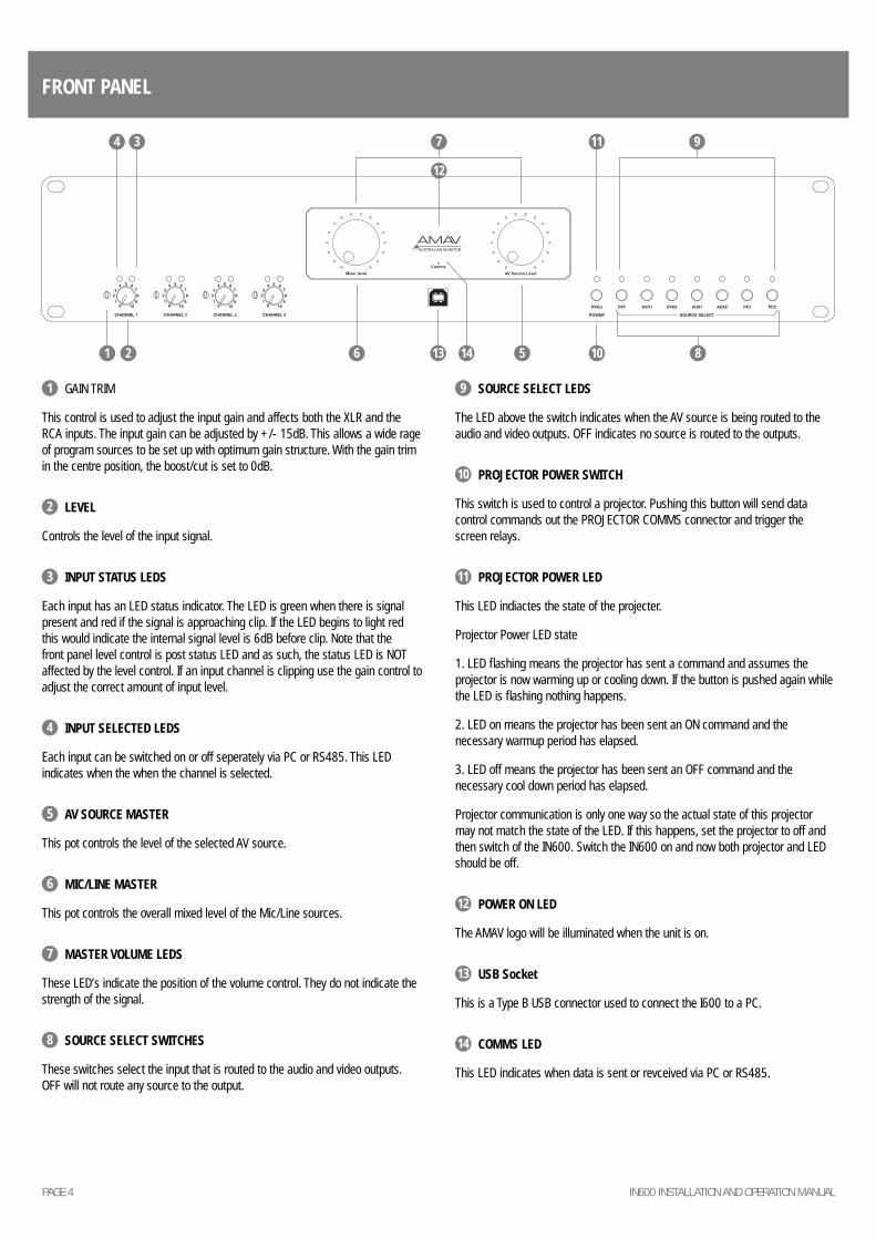
FRONT PANEL
8106 513 141 2
97
12
114 3
1 GAIN TRIM
This control is used to adjust the input gain and affects both the XLR and the RCA inputs. The input gain can be adjusted by +/- 15dB. This allows a wide rage of program sources to be set up with optimum gain structure. With the gain trim in the centre position, the boost/cut is set to 0dB.
2 LEVEL
Controls the level of the input signal.
3 INPUT STATUS LEDS
Each input has an LED status indicator. The LED is green when there is signal present and red if the signal is approaching clip. If the LED begins to light red this would indicate the internal signal level is 6dB before clip. Note that the front panel level control is post status LED and as such, the status LED is NOT affected by the level control. If an input channel is clipping use the gain control to adjust the correct amount of input level.
4 INPUT SELECTED LEDS
Each input can be switched on or off seperately via PC or RS485. This LED indicates when the when the channel is selected.
5 AV SOURCE MASTER
This pot controls the level of the selected AV source.
6 MIC/LINE MASTER
This pot controls the overall mixed level of the Mic/Line sources.
7 MASTER VOLUME LEDS
These LED’s indicate the position of the volume control. They do not indicate the strength of the signal.
8 SOURCE SELECT SWITCHES
These switches select the input that is routed to the audio and video outputs. OFF will not route any source to the output.
9 SOURCE SELECT LEDS
The LED above the switch indicates when the AV source is being routed to the audio and video outputs. OFF indicates no source is routed to the outputs.
10 PROJECTOR POWER SWITCH
This switch is used to control a projector. Pushing this button will send data control commands out the PROJECTOR COMMS connector and trigger the screen relays.
11 PROJECTOR POWER LED
This LED indiactes the state of the projecter.
Projector Power LED state
1. LED fl ashing means the projector has sent a command and assumes the projector is now warming up or cooling down. If the button is pushed again while the LED is fl ashing nothing happens.
2. LED on means the projector has been sent an ON command and the necessary warmup period has elapsed.
3. LED off means the projector has been sent an OFF command and the necessary cool down period has elapsed.
Projector communication is only one way so the actual state of this projector may not match the state of the LED. If this happens, set the projector to off and then switch of the IN600. Switch the IN600 on and now both projector and LED should be off.
12 POWER ON LED
The AMAV logo will be illuminated when the unit is on.
13 USB Socket
This is a Type B USB connector used to connect the I600 to a PC.
14 COMMS LED
This LED indicates when data is sent or revceived via PC or RS485.
PAGE 5IN600 INSTALLATION AND OPERATION MANUAL
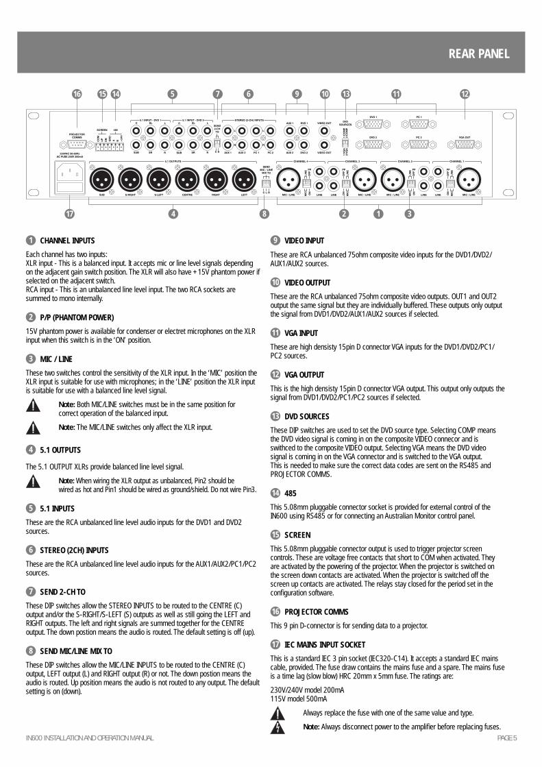
REAR PANEL
1 CHANNEL INPUTS
Each channel has two inputs: XLR input - This is a balanced input. It accepts mic or line level signals depending on the adjacent gain switch position. The XLR will also have +15V phantom power if selected on the adjacent switch. RCA input - This is an unbalanced line level input. The two RCA sockets are summed to mono internally.
2 P/P (PHANTOM POWER)
15V phantom power is available for condenser or electret microphones on the XLR input when this switch is in the ‘ON’ position.
3 MIC / LINE
These two switches control the sensitivity of the XLR input. In the ‘MIC’ position the XLR input is suitable for use with microphones; in the ‘LINE’ position the XLR input is suitable for use with a balanced line level signal.
Note: Both MIC/LINE switches must be in the same position for correct operation of the balanced input.
Note: The MIC/LINE switches only affect the XLR input.
4 5.1 OUTPUTS
The 5.1 OUTPUT XLRs provide balanced line level signal.
Note: When wiring the XLR output as unbalanced, Pin2 should be wired as hot and Pin1 should be wired as ground/shield. Do not wire Pin3.
5 5.1 INPUTS
These are the RCA unbalanced line level audio inputs for the DVD1 and DVD2 sources.
6 STEREO (2CH) INPUTS
These are the RCA unbalanced line level audio inputs for the AUX1/AUX2/PC1/PC2 sources.
7 SEND 2-CH TO
These DIP switches allow the STEREO INPUTS to be routed to the CENTRE (C) output and/or the S-RIGHT/S-LEFT (S) outputs as well as still going the LEFT and RIGHT outputs. The left and right signals are summed together for the CENTRE output. The down postion means the audio is routed. The default setting is off (up).
8 SEND MIC/LINE MIX TO
These DIP switches allow the MIC/LINE INPUTS to be routed to the CENTRE (C) output, LEFT output (L) and RIGHT output (R) or not. The down postion means the audio is routed. Up position means the audio is not routed to any output. The default setting is on (down).
9 VIDEO INPUT
These are RCA unbalanced 75ohm composite video inputs for the DVD1/DVD2/AUX1/AUX2 sources.
10 VIDEO OUTPUT
These are the RCA unbalanced 75ohm composite video outputs. OUT1 and OUT2 output the same signal but they are individually buffered. These outputs only output the signal from DVD1/DVD2/AUX1/AUX2 sources if selected.
11 VGA INPUT
These are high densisty 15pin D connector VGA inputs for the DVD1/DVD2/PC1/PC2 sources.
12 VGA OUTPUT
This is the high densisty 15pin D connector VGA output. This output only outputs the signal from DVD1/DVD2/PC1/PC2 sources if selected.
13 DVD SOURCES
These DIP switches are used to set the DVD source type. Selecting COMP means the DVD video signal is coming in on the composite VIDEO connecor and is swithced to the composite VIDEO output. Selecting VGA means the DVD video signal is coming in on the VGA connector and is switched to the VGA output. This is needed to make sure the correct data codes are sent on the RS485 and PROJECTOR COMMS.
14 485
This 5.08mm pluggable connector socket is provided for external control of the IN600 using RS485 or for connecting an Australian Monitor control panel.
15 SCREEN
This 5.08mm pluggable connector output is used to trigger projector screen controls. These are voltage free contacts that short to COM when activated. They are activated by the powering of the projector. When the projector is switched on the screen down contacts are activated. When the projector is switched off the screen up contacts are activated. The relays stay closed for the period set in the confi guration software.
16 PROJECTOR COMMS
This 9 pin D-connector is for sending data to a projector.
17 IEC MAINS INPUT SOCKET
This is a standard IEC 3 pin socket (IEC320-C14). It accepts a standard IEC mains cable, provided. The fuse draw contains the mains fuse and a spare. The mains fuse is a time lag (slow blow) HRC 20mm x 5mm fuse. The ratings are:
230V/240V model 200mA115V model 500mA
Always replace the fuse with one of the same value and type.
Note: Always disconnect power to the amplifi er before replacing fuses.
5 6 9 117 10 12141516 13
14 8 2 317
PAGE 6 IN600 INSTALLATION AND OPERATION MANUAL
INSTALLATION
POWER CONNECTION
Ensure the mains voltage supply matches the rear of the IN600 (+/- 10%).
Ensure that all system grounds (earth) are connected to a common point. Avoid powering equipment within a system from multiple power sources that may be separated by large distances. This will eliminate ground loops that are heard as 50/60Hz humming or buzzing in speakers and seen as moving or stationary bars on video equipment.
OUTPUT CONNECTION
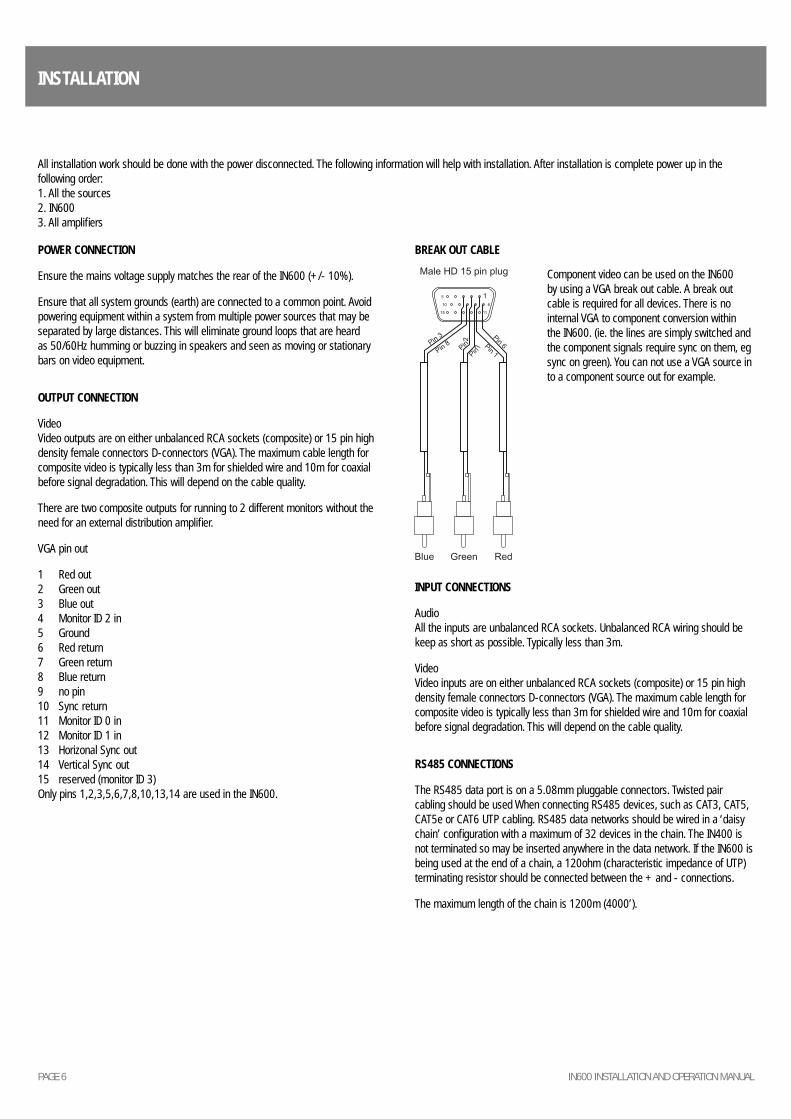
VideoVideo outputs are on either unbalanced RCA sockets (composite) or 15 pin high density female connectors D-connectors (VGA). The maximum cable length for composite video is typically less than 3m for shielded wire and 10m for coaxial before signal degradation. This will depend on the cable quality.
There are two composite outputs for running to 2 different monitors without the need for an external distribution amplifi er.
VGA pin out
1 Red out2 Green out3 Blue out4 Monitor ID 2 in5 Ground6 Red return7 Green return8 Blue return9 no pin10 Sync return11 Monitor ID 0 in12 Monitor ID 1 in13 Horizonal Sync out14 Vertical Sync out15 reserved (monitor ID 3)Only pins 1,2,3,5,6,7,8,10,13,14 are used in the IN600.
BREAK OUT CABLE
INPUT CONNECTIONS
AudioAll the inputs are unbalanced RCA sockets. Unbalanced RCA wiring should be keep as short as possible. Typically less than 3m.
VideoVideo inputs are on either unbalanced RCA sockets (composite) or 15 pin high density female connectors D-connectors (VGA). The maximum cable length for composite video is typically less than 3m for shielded wire and 10m for coaxial before signal degradation. This will depend on the cable quality.
RS485 CONNECTIONS
The RS485 data port is on a 5.08mm pluggable connectors. Twisted pair cabling should be used When connecting RS485 devices, such as CAT3, CAT5, CAT5e or CAT6 UTP cabling. RS485 data networks should be wired in a ‘daisy chain’ confi guration with a maximum of 32 devices in the chain. The IN400 is not terminated so may be inserted anywhere in the data network. If the IN600 is being used at the end of a chain, a 120ohm (characteristic impedance of UTP) terminating resistor should be connected between the + and - connections.
The maximum length of the chain is 1200m (4000’).
All installation work should be done with the power disconnected. The following information will help with installation. After installation is complete power up in the following order:1. All the sources2. IN6003. All amplifi ers
Component video can be used on the IN600 by using a VGA break out cable. A break out cable is required for all devices. There is no internal VGA to component conversion within the IN600. (ie. the lines are simply switched and the component signals require sync on them, eg sync on green). You can not use a VGA source in to a component source out for example.
PAGE 7IN600 INSTALLATION AND OPERATION MANUAL
RS485 COMMANDS
Data: 19200, 8N1All ASCII charactersThe commands are pure ASCII. So a hex value of 0xA5 (decimal 165) is sent as ASCII ‘A’ ‘5’, or 0x41 0x35.eg Command !04GR01??<CR> is sent as a hex string 0x21 0x30 0x34 0x47 0x52 0x30 0x31 0x3F 0x3F 0x0D
GET COMMANDS
OBJECT DATA RESPONSE DATA
!04GR01??<CR> Get source volume !04SR01XX<CR> XX-volume setting 00-FF (00 is min)
!08GR01??<CR> Get mic/line volume !08SR01XX<CR> XX-volume setting 00-FF (00 is min)
!04GL01??<CR> Get source mute state !04SL01YY<CR> YY-ON,OF,FL (On,Off, Flashing)
!08GLXX??<CR> Get mic/line enabled state XX-mic/line channel 01-04 !08SLXXYY<CR> XX-mic/line channel 01-04; YY-ON,OF,FL (On,Off, Flashing)
!10GLXX??<CR> Get source/projector state XX-source channel 01-06, 07-off, 08-projector
!10SLXXYY<CR> XX-source channel 01-06, 07-off, 08-projector; YY-ON,OF,FL (On,Off, Flashing)
SET COMMANDS
These commands are used to set values on the IN600. Good programming techinique should update control system visual info on the feedback responses not the ACK message, see Feedback table.
OBJECT DATA ACK NACK
!04SR01XX<CR> Set source volume XX-volume setting 00-FF (00 is min) !04A<CR> !04N<CR>
!08SR01XX<CR> Set mic/line volume XX-volume setting 00-FF (00 is min) !08A<CR> !08N<CR>
!04SB01SH<CR> Mute source !04A<CR> !04N<CR>
!08SBXXSH<CR> Enable/Disable Mic/Line XX-mic/line channel 01-04 !08A<CR> !08N<CR>
!10SBXXSH<CR> Select source/toggle projector XX-source channel 01-06, 07-off, 08-projector !10A<CR> !10N<CR>
FEEDBACK RESPONSES
These messages are sent from the IN600 when changes occur in the IN600. This includes RS485 Set commands as well as front panel changes.
OBJECT DATA
*01SR01XX<CR> When the source volume changes XX-volume setting 00-FF (00 is min)
*02SR01XX<CR> When the mic/line volume changes XX-volume setting 00-FF (00 is min)
*01SL01YY<CR> When the source mute state changes YY-ON,OF,FL (On,Off, Flashing)
*02SLXXYY<CR> When the Mic/Line enabled stated changes XX-mic/line channel 01-04; YY-ON,OF,FL (On,Off, Flashing)
*03SLXXYY<CR> When the selected source or projector changes XX-source channel 01-06, 07-off, 08-projector; YY-ON,OF,FL (On,Off, Flashing)
PAGE 8 IN600 INSTALLATION AND OPERATION MANUAL
SETUP / SOFTWARE
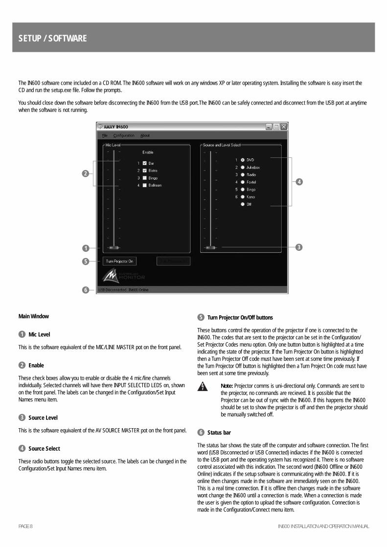
Main Window
1 Mic Level
This is the software equivalent of the MIC/LINE MASTER pot on the front panel.
2 Enable
These check boxes allow you to enable or disable the 4 mic/line channels individually. Selected channels will have there INPUT SELECTED LEDS on, shown on the front panel. The labels can be changed in the Confi guration/Set Input Names menu item.
3 Source Level
This is the software equivalent of the AV SOURCE MASTER pot on the front panel.
4 Source Select
These radio buttons toggle the selected source. The labels can be changed in the Confi guration/Set Input Names menu item.
5 Turn Projector On/Off buttons
These buttons control the operation of the projector if one is connected to the IN600. The codes that are sent to the projector can be set in the Confi guration/Set Projector Codes menu option. Only one button button is highlighted at a time indicating the state of the projector. If the Turn Projector On button is highlighted then a Turn Projector Off code must have been sent at some time previously. If the Turn Projector Off button is highlighted then a Turn Project On code must have been sent at some time previously.
Note: Projector comms is uni-directional only. Commands are sent to the projector, no commands are recieved. It is possible that the Projector can be out of sync with the IN600. If this happens the IN600 should be set to show the projector is off and then the projector should be manually switched off.
6 Status bar
The status bar shows the state off the computer and software connection. The fi rst word (USB Disconnected or USB Connected) indiactes if the IN600 is connected to the USB port and the operating system has recognized it. There is no software control associated with this indication. The second word (IN600 Offl ine or IN600 Online) indicates if the setup software is communicating with the IN600. If it is online then changes made in the software are immediately seen on the IN600. This is a real time connection. If it is offl ine then changes made in the software wont change the IN600 until a connection is made. When a connection is made the user is given the option to upload the software confi guration. Connection is made in the Confi guration/Connect menu item.
The IN600 software come included on a CD ROM. The IN600 software will work on any windows XP or later operating system. Installing the software is easy insert the CD and run the setup.exe fi le. Follow the prompts.
You should close down the software before disconnecting the IN600 from the USB port.The IN600 can be safely connected and disconnect from the USB port at anytime when the software is not running.
1 3
5
6
24
PAGE 9IN600 INSTALLATION AND OPERATION MANUAL
SETUP / SOFTWARE CONTINUED
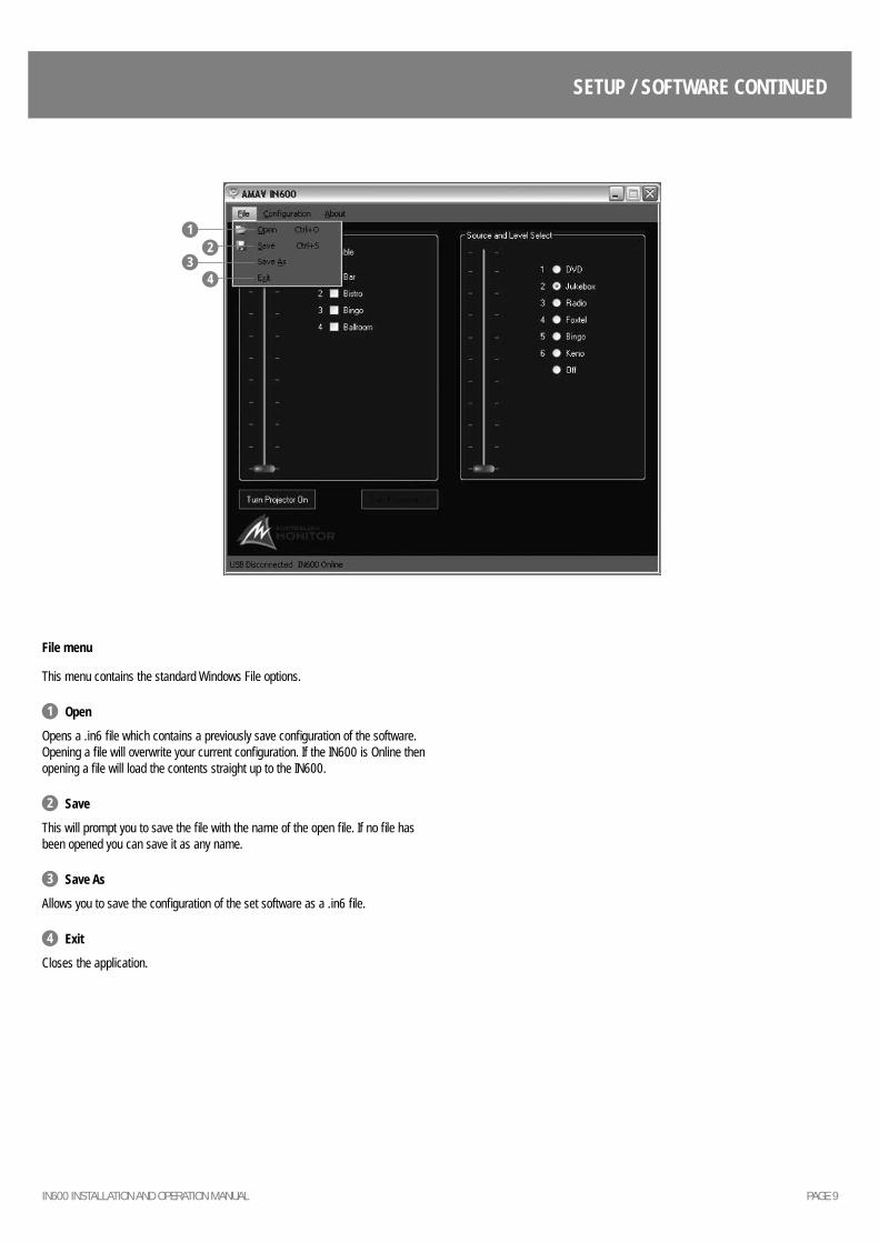
File menu
This menu contains the standard Windows File options.
1 Open
Opens a .in6 fi le which contains a previously save confi guration of the software. Opening a fi le will overwrite your current confi guration. If the IN600 is Online then opening a fi le will load the contents straight up to the IN600.
2 Save
This will prompt you to save the fi le with the name of the open fi le. If no fi le has been opened you can save it as any name.
3 Save As
Allows you to save the confi guration of the set software as a .in6 fi le.
4 Exit
Closes the application.
1
32
4
PAGE 10 IN600 INSTALLATION AND OPERATION MANUAL
SETUP / SOFTWARE CONTINUED
1
3
3
2
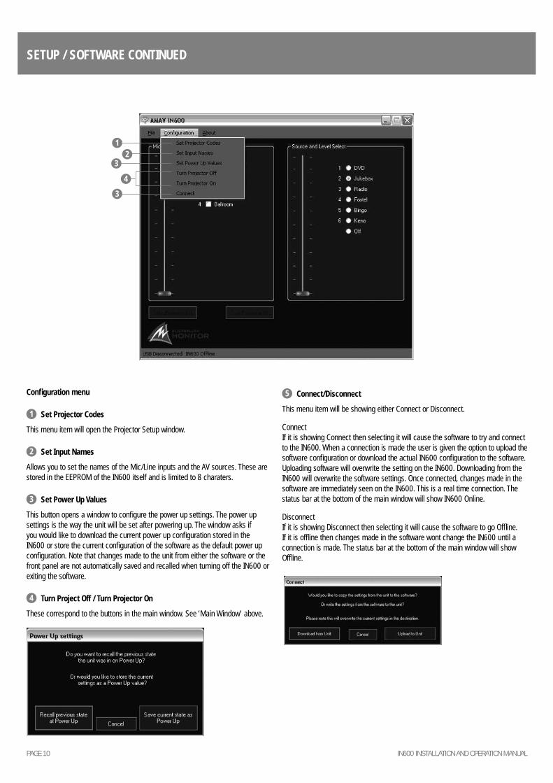
Confi guration menu
1 Set Projector Codes
This menu item will open the Projector Setup window.
2 Set Input Names
Allows you to set the names of the Mic/Line inputs and the AV sources. These are stored in the EEPROM of the IN600 itself and is limited to 8 charaters.
3 Set Power Up Values
This button opens a window to confi gure the power up settings. The power up settings is the way the unit will be set after powering up. The window asks if you would like to download the current power up confi guration stored in the IN600 or store the current confi guration of the software as the default power up confi guration. Note that changes made to the unit from either the software or the front panel are not automatically saved and recalled when turning off the IN600 or exiting the software.
4 Turn Project Off / Turn Projector On
These correspond to the buttons in the main window. See ‘Main Window’ above.
5 Connect/Disconnect
This menu item will be showing either Connect or Disconnect.
ConnectIf it is showing Connect then selecting it will cause the software to try and connect to the IN600. When a connection is made the user is given the option to upload the software confi guration or download the actual IN600 confi guration to the software. Uploading software will overwrite the setting on the IN600. Downloading from the IN600 will overwrite the software settings. Once connected, changes made in the software are immediately seen on the IN600. This is a real time connection. The status bar at the bottom of the main window will show IN600 Online.
DisconnectIf it is showing Disconnect then selecting it will cause the software to go Offl ine. If it is offl ine then changes made in the software wont change the IN600 until a connection is made. The status bar at the bottom of the main window will show Offl ine.
4
PAGE 11IN600 INSTALLATION AND OPERATION MANUAL
SETUP / SOFTWARE CONTINUED
3
2
1
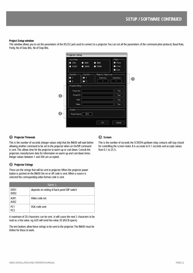
1 Projector Timeouts
This is the number of seconds (integer values only) that the IN600 will wait before allowing another command to be set to the projector when an On/Off command is sent. This allows time for the projector to warm up or cool down. Consult the projectors manufacturer data for information on warm up and cool down times. Integer values between 1 and 300 are accepted.
2 Projector Strings
These are the strings that will be sent to projector. When the projector power button is pushed on the IN600 the on or off code is sent. When a source is selected the corresponding video format code is sent.
Table 1
DVD1DVD2
depends on setting of back panel DIP switch
AUX1AUX2
Video code set
PC1PC2
VGA code sent
A maximum of 20 characters can be sent. /x will cause the next 2 characters to be read as a hex value. eg /x20 will send hex value 20 (ASCII-space).
The test buttons allow these strings to be sent to the projector. The IN600 must be Online for these to work.
3 Screen
This is the number of seconds the SCREEN up/down relay contacts will stay closed for controlling the screen motor. It is accurate to 0.1 seconds and accepts values from 0.1 to 25.5.
Project Setup windowThis window allows you to set the parameters of the RS232 port used to connect to a projector. You can set all the parameters of the communication protocol; Baud Rate, Parity, No of Data Bits, No of Stop Bits.
PAGE 12 IN600 INSTALLATION AND OPERATION MANUAL
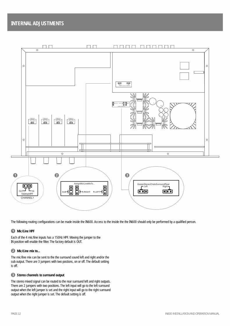
INTERNAL ADJUSTMENTS
1 Mic/Line HPF
Each of the 4 mic/line inputs has a 150Hz HPF. Moving the jumper to the IN position will enable the fi lter. The factory default is OUT.
2 Mic/Line mix to...
The mic/line mix can be sent to the the surround sound left and right and/or the sub output. There are 3 jumpers with two postions, on or off. The default setting is off.
3 Stereo channels to surround output
The stereo mixed signal can be routed to the rear surround left and right outputs. There are 2 jumpers with two positions. The left input will go to the left surround output when the left jumper is set and the right input will go to the right surround output when the right jumper is set. The default setting is off.
The following routing confi gurations can be made inside the IN600. Access to the inside the the IN600 should only be performed by a qualifi ed person.
1 2 3
PAGE 13IN600 INSTALLATION AND OPERATION MANUAL
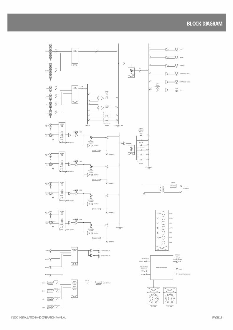
BLOCK DIAGRAM
PAGE 14 IN600 INSTALLATION AND OPERATION MANUAL
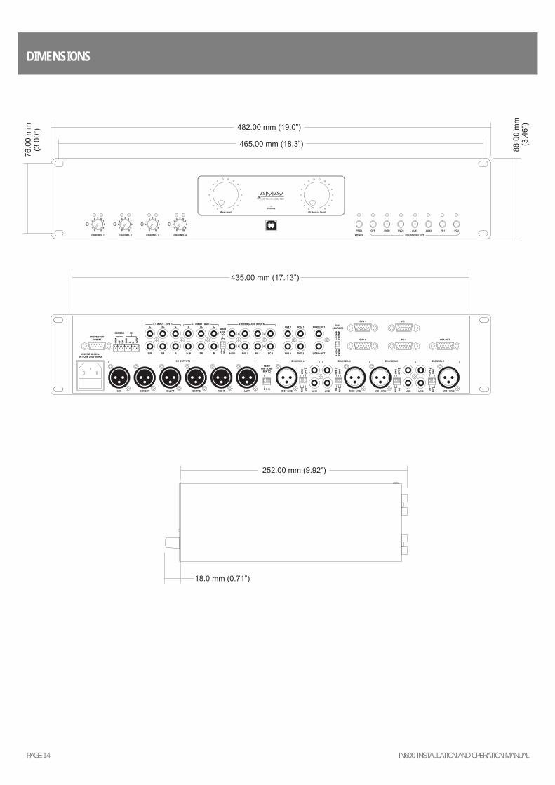
DIMENSIONS
PAGE 15IN600 INSTALLATION AND OPERATION MANUAL
SPECIFICATIONS
Line Audio THD <0.5% Noise Floor -90dBu Frequency Response (+/-3dB) 20-20kHz Gain (trim centre) XLR Mic 45dB XLR Line 0dB RCA line 12dB RCA switched 0dB Headroom 15dBu
Video VGA High speed RGB+Sync switching Video Composite 75ohm Buffered outputs Video follows Audio switching
Comms Type RS485 Baud Rate 9600 No of Data Bit 8 Parity None No of Stop Bits 1
Power Consumption (max) 30VA
Thermal output 1/8th power 100W (341.2Btu/hr)
SIZE (WXHXD) 482 x 88 x 270mm 19.” x 3.5” x 9.82”
NET WEIGHT 4.25kg 9.4lb
SHIPPING WEIGHT 6.5kg 14.3lb
SHIPPING DIMENSIONS (WXHXD) 520 x 190 x 360mm 20.5” x 7.5” x 14.2”

SYDNEY(NSW & ACT SALES)
1 Clyde Street
Silverwater
NSW 2128
Private Bag 149
Silverwater NSW 1811
Phone: (02) 9647 1411
Fax: (02) 9648 3698
Email:
MELBOURNE(VIC & TAS SALES)
22/277
Middleborough Road
Box Hill VIC 3128
PO Box 151 Blackburn
South VIC 3130
Phone: (03) 9890 7477
Fax: (03) 9890 7977
Email:
BRISBANE(QLD SALES)
42 Commercial Road
Fortitude Valley
QLD 4006
PO Box 2578 Fortitude
Valley BC QLD 4006
Phone: (07) 3852 1312
Fax: (07) 3252 1237
Email:
ADELAIDE(SA & NT SALES)
31 Walsh Street
Thebarton
SA 5031
PO Box 157
Hindmarsh SA 5007
Phone: (08) 8352 4444
Fax: (08) 8352 4488
Email:
PERTH(WA SALES)
3/11 Howe Street
Osborne Park WA 6017
PO Box 1281
Osborne Park BC
WA 6916
Phone: (08) 9204 0200
Fax: (08) 9244 3783
Email:
AUCKLAND(NZ SALES)
9C Piermark Drive
Albany 0752
New Zealand
PO Box 300-512
Albany 0752
Phone: (09) 415 9426
Fax: (09) 415 9864
Email:
AUSTRALIA AND NEW ZEALANDwww.australianmonitor.com.au
EUROPE / ASIA / MIDDLE EASTwww.australianmonitor.com.au
INTERNATIONAL SALES
1 Clyde Street Silverwater NSW 2128 Australia
Private Bag 149 Silverwater NSW 1811
Phone: + 61 2 9647 1411
Fax: + 61 2 9648 3698
Email: [email protected]