Embed Size (px)
Citation preview

AVC Advantage: HardwareFunctional Specifications
J. Alex Halderman and Ariel J. Feldman{jhalderm,ajfeldma}@cs.princeton.edu
March 8, 2008
1 Introduction 2 Program Memory 3 Primary Data Memory 4 Other Onboard Memories and RTC 5 Removable Memory Cartridge 6 Interrupt Control 7 Switches and Power Control 8 Parallel Printer Port 9 Operator Panel 10 Voter Panel 11 Voter Panel LCD and Keyboard 12 Voltage Monitor 13 I/O Port Index 14 Photographs

1 Introduction
In 1997, Buncombe County, North Carolina, purchased a number of AVC Advantage electronic voting machines for $5200 each. In January 2007, they retired these machines and auctioned them off through a government-surplus web site. Andrew Appel purchased one lot of 5 machines for a price of $82 for the lot [1], and we reverse engineered one of these machines to develop these functional specifications.
The machine we examined is an AVC Advantage revision “D”. It is a full-face direct-recording electronic (DRE) voting machine with a grid of switches and lights that voters use to make their selections. We were able to reverse engineer most of the machine’s hardware design using only visual inspection and electrical probing, and we filled in remaining details by partially disassembled the machine’s software using IDA [2]. After approximately six man-weeks of labor we produced this report.
This document describes the functionality of the AVC Advantage hardware, broken down into a number of subsystems. We have attempted to describe the hardware as software running on the machine sees it. Joshua Herbach used these specifications to developed a simulator for the machine [3], and we hope other election security researchers will also find this information useful.
[1] Andrew W. Appel. How I Bought Some Voting Machines on the Internet. February 8, 2007. http://www.cs.princeton.edu/~appel/avc/
[2] DataRescue sa/nv. IDA Pro Disassembler. http://www.datarescue.com/idabase[3] Joshua S. Herbach. Simulating the Sequoia AVC Advantage DRE Voting Machine. May 2007.
http://www.cs.princeton.edu/~herbach/SimulatingAVCAdvantage.pdf
The AVC Advantage we studied

0
0
0
1
A14
A14
A15 A4
A5
A6
A7
2 Program Memory
The AVC Advantage is built around a Z80 CPU, which executes software stored in three 64 KB EPROMs and, optionally, one 32 KB SRAM (which is not battery backed).
The program memory subsystem controls the low 32 KB of the Z80’s address space. The first 16 KB of the address space is always mapped to the first 16 KB of EPROM 1. Initially, the second 16 KB of the address space is unmapped (reads return 0xFF and writes have no effect), but programs can use an I/O instruction to direct this space to any 16 KB aligned region of the EPROMs or the SRAM.
Programs change the program memory mapping by outputting a byte to the I/O device on port 1. The following table shows how this value determines the mapping:
Start of region EPROM 1 EPROM 2 EPROM 3 SRAM
0x0000 0001XX11 0010XX11 0100XX11 1000XXX1 0x4000 0001XX10 0010XX10 0100XX10 1000XXX0 0x8000 0001XX01 0010XX01 0100XX01 N/A 0xC000 0001XX00 0010XX00 0100XX00 N/A
Unmapped 0000XXXX
Bits shown as X may be either 0 or 1. Other values should be considered illegal, as they will cause multiple chips to be being selected at once and may result in data corruption.
Notes: The SRAM is not installed on our machines. The motherboard will also accept 128 KB EPROM packages, which connect to the D FLIP-FLOP with a slightly different circuit. The bus transceiver’s OE line connects to a PAL (not shown); we assume it is high when the processor outputs to the I/O device on port 1.
Q4
Q5
Q6
Q7
M1
MREQIORQRDWR
RFSHWAIT
INTNMI
RESET
BUSRQBUSACK
A15A14A13A12A11A10
A9A8A7A6A5A4A3A2A1A0
D7D6D5D4D3D2D1D0
Z80
CPU A14
A13A12A11A10A9A8A7A6A5A4A3A2A1A0
DQ7
DQ6
DQ5
DQ4
DQ3
DQ2
DQ1
DQ0
CSWE
OE
32 K
B S
RA
M*
BY
A
AN
D
BY
A
AN
D
BY
A
AN
D
B
A
YC
D
OR
BY
A
AN
D
A15A14A13A12A11A10A9A8A7A6A5A4A3A2A1A0
DQ7
DQ6
DQ5
DQ4
DQ3
DQ2
DQ1
DQ0
EG
64 K
B E
PRO
M 1
A7
A6
A5
A4
A3
A2
A1
A0
B7
B6
B5
B4
B3
B2
B1
B0
DIROE B
US
TRA
NSC
EIV
ER D7
D6
D5
D4
D3
D2
D1
D0
Q7
Q6
Q5
Q4
Q3
Q2
Q1
Q0
CPOE
D F
LIP-
FLO
P
A0
A2
A1
E2
E1
Y4
Y7
Y6
Y5
Y3
Y2
Y1
Y0
3-to
-8 D
ECO
DER
4AS
4B
3A3B
2A2B
1A1B
OE
Y4
Y3
Y2
Y1
MU
LTIP
LEX
ERS
A15A14A13A12A11A10A9A8A7A6A5A4A3A2A1A0
DQ7
DQ6
DQ5
DQ4
DQ3
DQ2
DQ1
DQ0
EG
64 K
B E
PRO
M 2
A15A14A13A12A11A10A9A8A7A6A5A4A3A2A1A0
DQ7
DQ6
DQ5
DQ4
DQ3
DQ2
DQ1
DQ0
EG
64 K
B E
PRO
M 3
*
1
1256 KB
128 KB
JUMPER*
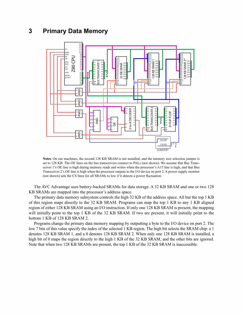
3 Primary Data Memory
Notes: On our machines, the second 128 KB SRAM is not installed, and the memory size selection jumper is set to 128 KB. The OE lines on the bus transceivers connect to PALs (not shown). We assume that Bus Trans-ceiver 1’s OE line is high during memory reads and writes when the processor’s A15 line is high, and that Bus Transceiver 2’s OE line is high when the processor outputs to the I/O device on port 2. A power supply monitor (not shown) sets the CS lines for all SRAMs to low if it detects a power fluctuation.
*
*A4
A5
A6
A7
A10
A11
A12
A13
A14
The AVC Advantage uses battery-backed SRAMs for data storage. A 32 KB SRAM and one or two 128 KB SRAMs are mapped into the processor’s address space.
The primary data memory subsystem controls the high 32 KB of the address space. All but the top 1 KB of this region maps directly to the 32 KB SRAM. Programs can map the top 1 KB to any 1 KB aligned region of either 128 KB SRAM using an I/O instruction. If only one 128 KB SRAM is present, the mapping will initially point to the top 1 KB of the 32 KB SRAM. If two are present, it will initially point to the bottom 1 KB of 128 KB SRAM 2.
Programs change the primary data memory mapping by outputting a byte to the I/O device on port 2. The low 7 bits of this value specify the index of the selected 1 KB region. The high bit selects the SRAM chip: a 1 denotes 128 KB SRAM 1, and a 0 denotes 128 KB SRAM 2. When only one 128 KB SRAM is installed, a high bit of 0 maps the region directly to the high 1 KB of the 32 KB SRAM, and the other bits are ignored. Note that when two 128 KB SRAMs are present, the top 1 KB of the 32 KB SRAM is inaccessible.
Q7Q7
Q7
Q0-
Q6
Q0-
Q6
M1
MREQIORQRDWR
RFSHWAIT
INTNMI
RESET
BUSRQBUSACK
A15A14A13A12A11A10
A9A8A7A6A5A4A3A2A1A0
D7D6D5D4D3D2D1D0
Z80
CPU A14
A13A12A11A10A9A8A7A6A5A4A3A2A1A0
DQ7
DQ6
DQ5
DQ4
DQ3
DQ2
DQ1
DQ0
CSWE
OE
32 K
B S
RA
M
A14A15A16
A13A12A11A10A9A8A7A6A5A4A3A2A1A0
DQ7
DQ6
DQ5
DQ4
DQ3
DQ2
DQ1
DQ0
CS2CS
WE
OE
128
KB
SR
AM
1
A14A15A16
A13A12A11A10A9A8A7A6A5A4A3A2A1A0
DQ7
DQ6
DQ5
DQ4
DQ3
DQ2
DQ1
DQ0
CS2CS
WE
OE
128
KB
SR
AM
2*
BY
A
AN
D
BY
A
AN
D
BY
A
AN
D
B
A
YC
D
OR
B
A
YC
D
E
F
AN
D
BY
A
AN
D
A7
A6
A5
A4
A3
A2
A1
A0
B7
B6
B5
B4
B3
B2
B1
B0
DIROE BU
S TR
AN
SCEI
VER
2
A7
A6
A5
A4
A3
A2
A1
A0
B7
B6
B5
B4
B3
B2
B1
B0
DIROE B
US
TRA
NSC
EIV
ER 1
D7
D6
D5
D4
D3
D2
D1
D0
Q7
Q6
Q5
Q4
Q3
Q2
Q1
Q0
CPOE
D F
LIP-
FLO
P
A0
A2
A1
E2
E1
Y4
Y7
Y6
Y5
Y3
Y2
Y1
Y0
3-to
-8 D
ECO
DER

0
1
0
1*
*
A8-
A15
The AVC Advantage has three onboard memories that are accessed exclusively using the processor’s device I/O facility: an 8 KB configuration EPROM, an 8 KB SRAM, and a real-time clock.
The 8 KB EPROM contains configuration data related to the machine, such as its serial number and a secret key used to authenticate vote data. Only 256 bytes are addressable. To read a byte from the EPROM, programs input a byte from the I/O device on port 0x3X (for any nibble X). Bits 8-15 of the processor’s address bus during the I/O operation are used as bits 0-7 of the EPROM address; the EPROM’s other address bits are set to 0.
The machine also contains an 8 KB SRAM, which is not battery backed. Programs select a 256 byte region of the SRAM by outputting a byte to the I/O device on port 0x95. Bits 0, 1, and 2 of the outputted value set bits 8, 9, and 10 of the address; bit 7 sets bit 11 of the address; and bit 6 sets bit 12 of the address. Programs read and write to addresses within the selected 256 byte region by inputting and outputting bytes to port 0x96. Bits 8-15 of the processor’s address bus are used as bits 0-7 of the SRAM address.
The real-time clock chip provides the date and time as well as a few tens of bytes of battery-backed storage. Programs set an address to read or write by outputting a byte to port 0x50. To write to this address, the program outputs a byte to port 0x52. To read, it inputs a byte from port 0x53. When not preceded by an address-set command, reads return 0xFF and writes have no effect. The address must be set again after each read or write, or after the processor resets. Some RTC addresses behave like normal RAM, but others relate to the chip’s clock functions. For details, see the datasheet for part BQ3285.
A8-
A15
A7
A4
A5
A6
4 Other Onboard Memories and RTC
Notes: The bus transceiver’s OE line connects to a PAL (not shown); we assume it is high when the processor inputs or outputs to the I/O devices mentioned below. The 3-to-8 decoder’s E1 line also connects to a PAL. We infer that it is high when the processor inputs or outputs to I/O devices in the port family 0x9X.
Q6
Q7
Q2
Q1
Q0
M1
MREQIORQRDWR
RFSHWAIT
INTNMI
RESET
BUSRQBUSACK
A15A14A13A12A11A10
A9A8A7A6A5A4A3A2A1A0
D7D6D5D4D3D2D1D0
Z80
CPU A12
A11A10A9A8A7A6A5A4A3A2A1A0
DQ7
DQ6
DQ5
DQ4
DQ3
DQ2
DQ1
DQ0
CSCS2WE
OE
8 K
B S
RA
M
A12A11A10A9A8A7A6A5A4A3A2A1A0
DQ7
DQ6
DQ5
DQ4
DQ3
DQ2
DQ1
DQ0
CS
OE
8 K
B E
PRO
M
DQ7
DQ6
DQ5
DQ4
DQ3
DQ2
DQ1
DQ0
CS
AS
DS
R/!W
“BQ
3285
” RTC
BY
A
AN
D
BY
A
AN
D
A7
A6
A5
A4
A3
A2
A1
A0
B7
B6
B5
B4
B3
B2
B1
B0
DIROE B
US
TRA
NSC
EIV
ER D7
D6
D5
D4
D3
D2
D1
D0
Q7
Q6
Q5
Q4
Q3
Q2
Q1
Q0
CPOE
D F
LIP-
FLO
PR
D
CP
S
Q
!Q
D F
LIP-
FLO
P
A0
A2
A1
E1
Y4
Y7
Y6
Y5
Y3
Y2
Y1
Y0
3-to
-8 D
ECO
DER
A0
A2
A1
E2
E1
Y4
Y7
Y6
Y5
Y3
Y2
Y1
Y03-
to-8
DEC
OD
ER A1
A0
OE
Y3
Y2
Y1
Y0
2-to
-4 D
ECO
DER
BY
A
AN
D
BY
A
OR

5 Removable Memory Cartridge
The AVC Advantage uses removable memory cartridges to transfer ballot definitions, election results, and other data. We understand one variety of memory cartridge—the “Rev. C” Results Cartridge. Other cartridge models may differ somewhat.
The “Rev. C” Results Cartridge contains 96 KB of battery-backed SRAM. It also maintains several pieces of internal state: a 17 bit working address, an LED status bit, an arming bit, an address invalidator bit, and an automatic address increment (AAI) enable bit. These reset to 0 when the cartridge is discon-nected or the machine powers down.
The machine has two cartridge slots, which seem to be interchangeable as far as the hardware is concerned. Programs interface to the cartridges by inputting and outputting bytes to a family of I/O ports. Each of the commands below indicates the ports used for Slot A/Slot B.
out B0/B8 Set Working Address Bits 0-7 Bits 0-7 of the outputted byte set bits 0-7 of the working address.
out B1/B9 Set Working Address Bits 8-12 Bits 0-5 of the outputted byte set bits 8-12 of the working address. Bit 7 sets the address invalidator bit.
out B3/BB Set Working Address Bits 13-16 Bits 0-3 of the outputted byte set bits 13-16 of the working address. Bit 6 sets the LED status bit; the cartridge’s LED illuminates whenever this bit is 1. Bit 7 sets the AAI enable bit, described below.
in B2/BA Read Byteout B2/BA Write Byte
Read Byte returns the SRAM value at the working address, or 0xFF if the address is out of range or the address invalidator bit is 1.Write Byte stores the outputted value to SRAM at the working address, as long as the address is in range, the address invalidator bit is 0, and the arming bit is 1.If the AAI enable bit is 1, then after each read or write command, the value of the low 8 bits of the working address is incremented modulo 256.
in B4/BC Read ID ByteReturns a 1-byte code identifying the cartridge and its capabilities. The “Rev. C” Results Cartridge returns the value 0x12.
out B5/BD Set Arming StateSets the arming bit. If the high four bits of the outputted value match the high four bits returned by the Read ID Byte command, then the arming bit is set to 1; otherwise, the bit is set to 0. (For example, in the “Rev. C” Results Cartridge, the arming bit is set to 1 if the outputted byte is 0x1X, where X can be any value.)

6 Interrupt Control
The AVC Advantage pairs a Z80 CPU with two Z84C30 counter/timer circuits (CTCs). Each CTC provides four programmable interrupt channels. The two chips are directly connected to the CPU and daisy chained for simultaneous operation. They operate according to the Z80’s “mode 2” interrupt scheme: when an interrupt occurs, the processor jumps to a location specified by an interrupt table in memory. There is one entry in the table for each of the CTC channels. Any of the eight channels can be programmed to generate an interrupt after a specified number of clock cycles or after counting down a number of pulses from an external trigger wired to the channel’s CLK/TRG pin. When the interrupt fires, the channel can optionally output a pulse on its ZC/TO pin, which may be interfaced to other hardware. Each CTC channel may be programmed independently using its assigned I/O port; consult the manual [1] for details. The following table describes the input and output signals wired to the channels:
Chip/ I/O Input (CLK/TRG) Pins /Channel Port Output (ZC/TO) PinsCTC0/0 0xA0 Input: Binary counter output; inverts every 64 system clock ticksCTC0/1 0xA1 Output: [Test pin]CTC0/2 0xA2 Input: Connected to !INT pin on RTC (see BP3285 datasheet)CTC0/3 0xA3 Input: High when cartridge present in aux. cartridge slot (slot B)CTC1/0 0xA8 Input: Low during I/O requests to port 0x4F Output: [Test pin]CTC1/1 0xA9 Output: Drives the Operator Panel speaker. Each output pulse from
this channel switches the speaker signal from a high value to a low value or vise versa, forming a square wave.
CTC1/2 0xAA Input: Printer port, pin 10 (!ACK signal)CTC1/3 0xAB None
Non-Maskable InterruptsNMIs, a second type of interrupt, can be generated by a watchdog timer circuit or by one of the
motherboard’s PALs. Unlike regular interrupts, they cannot be suppressed by disabling interrupts in the CPU. Control jumps to a fixed address—0x66—in response to any NMI.
The watchdog circuit triggers when the Watchdog Input bit of the power control register (see Section 7) remains unchanged for more than 1.6 seconds. If the register’s “PWRON” bit is 1, the watchdog timeout causes an NMI.
One of the PALs can also trigger an NMI. We infer that it does this when it detects an opcode being fetched from data RAM (i.e., the CPU indicates !M1 ^ !MREQ ^ A15). Opcode fetches from the 32 KB SRAM that is part of program memory do not trigger NMIs. When this NMI occurs, the circuit sets a status bit, initially 0, to 1. Programs query this bit by inputting from port 0x07; bit 1 of the value is the status bit, while bits 0 and 2-7 are 0. Programs clear this status bit by outputting any value to port 0x05.
[1] Z80 Family CPU Peripherals User Manual, http://www.zilog.com/docs/z80/um0081.pdf

7 Switches and Power Control
Inside the voting machine’s case there is a panel with a “Power On-Off” knob, a “Polls Open / Polls Closed” locking switch, and a “Print More” button. Software checks the status of these switches (and of the machine’s main battery backup and charging circuit) by inputting a byte from I/O port 0x06. The following table describes the meaning of this value:
Input Byte, Port 0x06
Bit 0 “Print More” 1 if “Print More” button depressed, 0 otherwiseBit 1 “Polls Open” 1 if lock in “Polls Open” position, 0 otherwiseBit 2 “Polls Closed” 1 if lock in “Polls Closed” position, 0 otherwiseBit 3 Unused 0 alwaysBit 4 Unused 0 alwaysBit 5 “ON” 1 if power knob in on position, 0 otherwiseBit 6 “AC ON” 1 if AC power cord attached to power, 0 otherwise Bit 7 “NO BATT” 1 if main (12V) battery disconnected, 0 otherwise
When the machine is off, turning the “Power On-Off” knob to the “On” position briefly applies power to the motherboard. The machine’s software immediately sets a bit in the power control register (described below) that causes the power supply to continue powering the board. Even if the user moves the knob away from the “On” position, the machine will remain powered on until the software clears this bit. Software sets the power control register by outputting a byte to I/O port 0x04. The following table describes the meaning of this value:
Output Byte, Port 0x04
Bit 0 “PWRON” 1 to continue powering the motherboard, 0 to shut offBit 1 UnusedBit 2 Voter Panel Bus Power 1 to power voter panel electronics, 0 to shut offBit 3 Voter Panel Light Power 1 to power voter panel LEDs and light, 0 to shut offBit 4 UnusedBit 5 UnusedBit 6 UnusedBit 7 Watchdog Input Periodic liveness signal sent to the watchdog timer circuit
(see Section 6)

8 Parallel Printer Port
The AVC Advantage contains a Seiko DPU-414 thermal roll printer mounted inside its case. The system communicates with the printer via a standard 25-pin parallel port (SPP mode). To control the parallel port, software inputs and outputs bytes to devices attached to three of the processor’s I/O ports. Outputting to I/O port 0x90 sets the value of the parallel port’s data pins; outputting to I/O port 0x92 sets the value of the parallel port’s control pins. These values are latched to the output pins, so the pin values will not change until they are overridden with another I/O command. Inputting from I/O port 0x91 retrieves the immediate state of the parallel port’s status pins. The diagram below illustrates the correspondence between the I/O bytes and the parallel port pinout:
For a description of how typical software interfaces to a standard parallel printer, see Section 8 of http://www.lvr.com/files/ibmlpt.txt.
D6D7 D5 D4 D3 D2 D1 D0
C6C7 C5 C4 C3 C2 C1 C0S6S7
1 1 1
S5 S4 S3 S2 S1
-Ack
-Strobe
-AutoFd
-Init
-Select
+Busy
+PaperEnd
+SelectIn
-Error
S0
13 12 11 10
25 24 23 22 21 20 19 18 17 16 14
9 8 7 6 5 4 3 2 1
15
Output Byte, Port 0x90, “Data”
Input BytePort 0x91
“Status”
Output BytePort 0x92“Control”

9 Operator Panel
Poll workers conduct setup and administrative functions using the AVC Advantage’s operator panel. The operator panel contains 16 LEDs, 14 momentary action switches, and an LCD capable of displaying two lines of 24 characters (5x8 pixels). Programs interact with the operator panel by inputting and outputting bytes to I/O devices attached to several ports, as described below.
An Hitachi HD 44780A00 LCD Controller drives the LCD display. Programs interface with this chip by using several I/O ports. These ports determine the state of the chip’s E, RS, and R/W status lines, as described in the following table, and cause the controller to input or output a byte from the processor’s data bus. Refer to the controller’s data sheet for a description of its configuration and character display com-mands.
Port Dir E RS R/W 0x10 Out 1 0 0 0x11 In 1 0 1 0x12 Out 1 1 0 0x13 In 1 1 1 Other - 0 - -
Programs poll the status of the switches by inputting a byte from the I/O devices on ports 0x14 and 0x15. Each bit of the response corresponds to the status of a single switch, as described in the table below. A 1 bit indicates that the switch is depressed.
Programs set the status of the LEDs by outputting a byte to the I/O devices on ports 0x16 and 0x17. Each bit corresponds to a single LED, as described in the table below. A bit 1 causes the LED to illuminate. The LEDs hold their state until the program writes a new value to the port.
Bit:
See
Not
e*
7 6 5 4 3
Switches[In] Port 0x14
2 1 0
- ‘6’
‘5’
‘4’
‘3’
‘2’
‘1’
Switches[In] Port 0x15
7 6 5 4 3 2 1 0
Nex
t/No
Star
t/Yes
‘12’
‘11’
‘10’ ‘9’
‘8’
‘7’
LEDs[Out] Port 0x16
Bat
tery
Low
7 6 5 4 3 2 1 0
AC
Pow
er‘6
’‘5
’‘4
’‘3
’‘2
’‘1
’
LEDs[Out] Port 0x17
7 6 5 4 3 2 1 0
Test
*A
ctiv
ate
‘12’
‘11’
‘10’ ‘9’
‘8’
‘7’
Notes: Bit 7 of port 0x17 controls the ‘Test’ LED and also provides the input to bit 7 of port 0x14. This allows programs to verify the status of the LED during testing. Writes to any port marked ‘In’ may result in an unstable condition.

10 Voter Panel
Voters select candidates using the machine’s voter panel. The panel contains 504 push-button switches and 504 corresponding LEDs. These are divided into two groups of six subpanels, the left subpanel group and the right subpanel group. Each subpanel contains 6 columns and 7 rows of switches and LEDs. This diagram shows the voter panel layout:
Subpanel, port 0x45
Subpanel, port 0x44
Subpanel, port 0x43
Subpanel, port 0x42
Subpanel, port 0x41
Subpanel, port 0x40
Left Subpanel Group
Subpanel, port 0x4D
Subpanel, port 0x4C
Subpanel, port 0x4B
Subpanel, port 0x4A
Subpanel, port 0x49
Subpanel, port 0x48
Right Subpanel Group
Column 0 Column 1 Column 2 Column 3 Column 4 Column 5
Row 0123456
For each subpanel group, programs select an active column by outputting a value from 0–5 to the subpanel group’s “select column” I/O port (0x47 for the left group, 0x4F for the right group). The selected column, initially column 0, remains active until it is overridden. It applies simultane-ously to all six subpanels in the subpanel group.
Programs address each individual subpanel using its I/O port, as shown at right. Inputting a byte from the subpanel’s port retrieves the state of the active column’s switches at that instant. Each bit from 0–6 represents the state of the switch in that row of the active column—a 1 means the switch is depressed, and a 0 means it is released. The remaining bit is always 0.
Outputting a byte to a subpanel’s port sets the display pattern for that subpanel. Each bit from 0–6 controls the LED in the corresponding row, with a 1 indicating that the LED will illuminate. The new display pattern immediately sets the state of the LEDs in the subpanel’s active column. However, if the active column changes, the LEDs in the new active column take on the existing display pattern for each subpanel. The LEDs in the old active column turn off, but this isn’t visible for at least 1/6 second. Effec-tively, this persistence allows programs to control the appearance of all the LEDs even though the subpanels can only drive one column at a time.
A light inside the booth helps voters read the voter panel. Programs control the light by outputting a byte to port 0x46. The light, which is initially off, will turn on if bit 7 of this value is 1 or turn off if bit 7 is 0 (the other bits are ignored). It remains in that state until overridden by another I/O command. Reads from 0x46 return 0.
Voters finalize their selections by pressing a “Cast Vote” button, which illuminates after the voter has selected a candidate for each race. Programs control the illumination in a similar manner to the booth light, using bit 6 of a byte outputted to port 0x4E. Programs check the state of the button by inputting a byte from port 0x4E. If the button is not illuminated, bits 0 and 1 of the value will both be 1, regardless of the button’s position. If the button is illuminated, then, if the button is depressed, bit 0 will be 0 and bit 1 will be 1, and if the button is released, bit 0 will be 1 and bit 1 will be 0. In all cases, the unspecified bits will be 0.
Labe
ls
Subpanel:
LED
sB
utto
ns
11 Voter Panel LCD and Keyboard
The AVC Advantage allows voters to confirm their selections using a two-line LCD display. Programs control it just like they control the operator panel LCD display, except that they use ports 0x70, 0x71, 0x72, and 0x73.
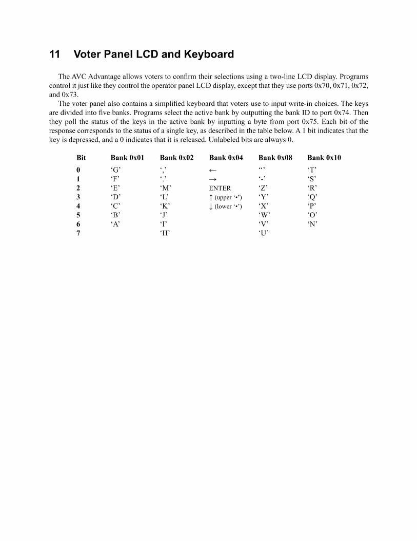
The voter panel also contains a simplified keyboard that voters use to input write-in choices. The keys are divided into five banks. Programs select the active bank by outputting the bank ID to port 0x74. Then they poll the status of the keys in the active bank by inputting a byte from port 0x75. Each bit of the response corresponds to the status of a single key, as described in the table below. A 1 bit indicates that the key is depressed, and a 0 indicates that it is released. Unlabeled bits are always 0.
Bit Bank 0x01 Bank 0x02 Bank 0x04 Bank 0x08 Bank 0x10 0 ‘G’ ‘,’ ← ‘‘’ ‘T’ 1 ‘F’ ‘.’ → ‘-’ ‘S’ 2 ‘E’ ‘M’ ENTER ‘Z’ ‘R’ 3 ‘D’ ‘L’ ↑ (upper ‘•’) ‘Y’ ‘Q’ 4 ‘C’ ‘K’ ↓ (lower ‘•’) ‘X’ ‘P’ 5 ‘B’ ‘J’ ‘W’ ‘O’ 6 ‘A’ ‘I’ ‘V’ ‘N’ 7 ‘H’ ‘U’

12 Voltage Monitor
The AVC Advantage monitors the voltage level of its power supplies and batteries using an ADC0808 eight-channel analog-to-digital converter. Software selects one of the ADC inputs to monitor by writing a byte to port 0x60. This activates the ADC’s ALE line and latches the low three bits of the outputted byte into the chip’s address latch; they will select an analog input from 0-7.
To sample the selected input and begin conversion, the program outputs an arbitrary byte to port 0x61, which pulses the ADC’s START line. The software checks the status of the conversion by inputting a byte from port 0x63. Bit 7 indicates the state of the ADC’s EOC pin, while bits 0-6 are 0. EOC is initially high and remains high for 8 ADC clock cycles after the start of the conversion; it then goes low for 56 ADC clock cycles until the conversion is complete; finally, it returns to a high state and the conversion result is avail-able to be read. The program reads the result by inputting a byte from port 0x62. This causes the chip’s output enable pin to go high, placing the conversion result on the data bus.
The ADC’s clock runs 128 times slower than the system clock. A binary counter divides the system clock signal so that the ADC’s clock input inverts every 64 system clock cycles. This same signal drives the CTC0 channel 0 CLK/TRG input (see Section 6).

13 I/O Port Index
Port Description . . . . . . . . . . . . . . . . . . . Page
0x Motherboard
01 out ROM bank select . . . . . . . . . . . 202 out 128 KB RAM page select. . . . . 304 out Power control register set . . . . . 705 out NMI status clear . . . . . . . . . . . . 606 in Switch and power status get . . . 707 in NMI status get . . . . . . . . . . . . . . 6
1x Operator Panel
10 out LCD control . . . . . . . . . . . . . . . 911 in LCD control . . . . . . . . . . . . . . . 912 out LCD control . . . . . . . . . . . . . . . 913 in LCD control . . . . . . . . . . . . . . . 914 in Switches A get . . . . . . . . . . . . . . 915 in Switches B get . . . . . . . . . . . . . 916 out LEDs A set . . . . . . . . . . . . . . . . 917 out LEDs B set . . . . . . . . . . . . . . . . 9
3x 8 KB Config. EPROM
30-3F in Read byte . . . . . . . . . . . . . . . . . 4
4x Voter Panel
40-45 in/out Left panel switches / LEDs . . . 1046 in/out Booth light control . . . . . . . . . 1047 out Left panel column select . . . . . 1048-4D in/out Right panel switches / LEDs . . 104E in/out Cast vote button/light . . . . . . . 104F out Right panel column select . . . . 10
5x RTC
50 out Set address . . . . . . . . . . . . . . . . 452 out Write byte . . . . . . . . . . . . . . . . . 453 in Read byte . . . . . . . . . . . . . . . . . 4
Port Description . . . . . . . . . . . . . . . . . . . Page
6x Voltage Monitor (ADC)
60 out Select input . . . . . . . . . . . . . . . 1261 out Start sample . . . . . . . . . . . . . . 1262 in Read result . . . . . . . . . . . . . . . 1263 in Check status . . . . . . . . . . . . . . 12
7x Voter Panel LCD
70 out LCD control . . . . . . . . . . . . . . .1171 in LCD control . . . . . . . . . . . . . . .1172 out LCD control . . . . . . . . . . . . . . .1173 in LCD control . . . . . . . . . . . . . . .1174 out Key bank select . . . . . . . . . . . . .1175 in Key bank status get . . . . . . . . . .11
9x Printer / 8 KB RAM
90 out Printer “data” byte set . . . . . . . . 891 in Printer “status” byte get . . . . . . 892 out Printer “control” byte set . . . . . 895 out 8 KB RAM page select . . . . . . 496 in/out 8 KB RAM read/write byte . . . . 4
Ax Interrupt Control (CTC)
A0-A3 out CTC0 channels 0-3 program . . . 6A8-AB out CTC1 channels 0-3 program . . . 6
Bx Cartridge A/B (Vote/Aux)
B0/B8 out Address bits 0-7 set . . . . . . . . . . 5B1/B9 out Address bits 8-12 set . . . . . . . . . 5B2/BA in/out Read/write byte . . . . . . . . . . . . . 5B3/BB out Address bits 13-16 set . . . . . . . . 5B4/BC in ID byte get . . . . . . . . . . . . . . . . 5B5/BD out Arming state set . . . . . . . . . . . . 5

14 Photographs
AVC Advantage motherboard
Connectors (clockwise from upper right): memory cartridges (2), parallel printer port,power in, voter panel power (2), printer power, voter panel data (2).

Results Cartridge “Rev. C”
Control panel (detail)