Embed Size (px)
Citation preview

ACM20.2032
Aviation Condition Monitoring Handbook
P.849132, issue 3
© Parker Hannifin, 2007
www.parker.com/cmc


ACM20.2032Aviation Condition Monitoring Handbook
P.849132, issue 3
© Parker Hannifin, 2007
www.parker.com/cmc

Parker Hannifin ACM20.2032
g
2
ACM20.2032: Declaration of conformity and certificate of manufacturer
CE conformity
The ACM20.2032 is in conformity with the protection requirements of the following European Standards in English:
n Directive 94/9/EC of the European Parliament and the Council, for equipment intended for use in potentially explosive atmospheres (ATEX)
n EN50021:1999, Electrical apparatus for potentially explosive atmospheres, type ‘n’ protection
n BS EN60079-15:2005, Electrical equipment for use in gases, mists and vapours, non-incendive type ‘n’, and
n EN61326, Electrical equipment for measurement, control and laboratory use, EMC requirements.
Markings on the enclosure
The nameplate attached to the lid of the enclosure provides the name and address of the manufacturer:
Parker Hannifin (UK) Ltd, Filter Division Europe, Condition Monitoring Centre, Brunel Way, Thetford, Norfolk, IP24 1HP
and the Certification number of the ATEX Category 3 Certificate:
EPSILON 06ATEX2093X
The X condition placed by the certification body relates to the UV specification of the handset material. Due to the handset being stowed under the main enclosure lid, it has been classed as tolerable to acceptable levels.
Complete part number
This manual describes the ACM20.2032 equipment.
‘ACM20’ is the Aviation Contamination Monitor ‘20’ is the Particle counter group of products ‘3’ is for Fuel ‘2’ is for MTD (medium test dust) particle count calibration
Product serial number
The serial number consists of seven digits, for example: BB84001
‘BB’ is the month and year ‘84’ is the product group. The last three digits are entered sequentially through a month, reverting to ‘001’ at the
beginning of each month.

Parker Hannifin ACM20.2032
g
3
Certification identification
Conditions for safe use
Battery charging must NOT be carried out in the hazardous area and NOT during use.
The download of data must NOT be carried out in the hazardous area.
To ensure compliance with the certification, users are NOT permitted to open the unit under any circumstance. Doing so will invalidate the unit’s calibration and it would NOT be suitable for Hazardous area use.
Laser safety
This product contains an invisible infrared 5mW laser.
Dismantling of this product is not permitted.
The internal protective housing label, Class 3, which is mounted on the laser module contains the following information:
‘This product is a Class I laser product which complies with both USA21 CFR 1040.10 & 1040.11 and (BS) EN 608285-1’
Note: Users are not required to access the laser radiation source and should never do so.
Complies with all applicable European Directives
EC mark
Equipment group
Equipment category
Gas
Explosion protection
Type of protection
Type of protection
Gas group
Temperature class
DANGER – INVISIBLE LASERRADIATION WHEN OPEN.AVOID DIRECT EXPOSURE
TO BEAM.

Parker Hannifin ACM20.2032
g
4
Overview
Parker Hannifin’s ACM20.2032 is a Laser Particle Counter. This battery operated, aviation fluid contamination measurement instrument is designed for use in ATEX category 3 areas and is made up of two parts, the main unit and a hand-held controller.
The main unit consists of a Ex e enclosure, which is protected by restricted breathing and has a hinged lid to cover the controls. Mounted on the top of the enclosure is an ITW Series 57 miniature vandal-resistant switch to turn the unit on and off, a valve control knob which is attached to a link shaft passing into the enclosure and two connectors, one 3-pin and one 8-pin. Lanyard mounted covers allow for battery charging and data transfer in non-hazardous areas.
With the lid closed, the enclosure measures 305mm tall x 200 mm deep x 330 mm wide. Two hoses passing through Lapp skintop cable glands on the left-hand side of the enclosure allow for fluid to be transferred in and out for analysis. On the base of the unit is a restricted-breathing test point.
The hand-held controller is protected by energy limitation and measures 175mm long x 95mm wide x 30mm deep. It is connected to the main enclosure via two Lapp skintop cable glands and a spiral wound cable. It has a 16-button keypad and a 55 x 55 mm LCD screen.

Parker Hannifin ACM20.2032
g
5
ContentsACM20.2032: Declaration of conformity and Certificate of manufacturer ................................................................ 2Conditions for safe use........................................................................ 3Laser Information ................................................................................ 3Overview .............................................................................................. 4
Introduction ...............................................................................6Features ................................................................................................ 6Benefits ................................................................................................ 7
Getting started ........................................................................11Setting the time ................................................................................. 11Setting the date ................................................................................. 12
Basic operation .......................................................................13Independent flow test....................................................................... 15Particle count details ......................................................................... 16Entering a test identification code ................................................... 17Viewing a stored test by ID code or test number ............................ 19Alarm levels........................................................................................ 20Automatic testing .............................................................................. 21Calibration ......................................................................................... 22Adjusting screen brightness .............................................................. 22
Reference .................................................................................23Interpreting data ............................................................................... 23ISO contamination charts .................................................................. 27Hydraulic circuit diagram ................................................................. 29Logic diagram .................................................................................... 29Connectors and Serial interface........................................................ 30Measurement accuracy...................................................................... 30Diagnostic codes ................................................................................ 31Technical specifications ..................................................................... 33Top, front and rear views of the unit ............................................... 34Battery charger B.84.647 ................................................................... 35Ordering information........................................................................ 36Operation checklist............................................................................ 36
INTRODUCTION
Parker Hannifin ACM20.2032
g
6
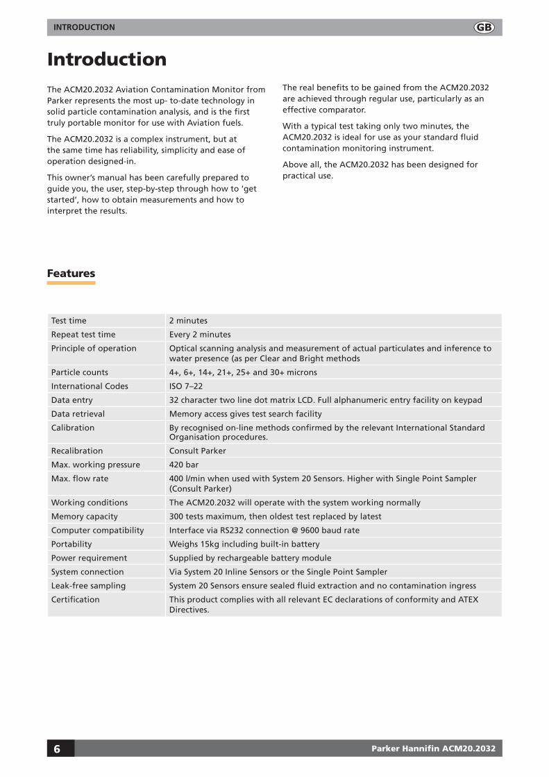
IntroductionThe ACM20.2032 Aviation Contamination Monitor from Parker represents the most up- to-date technology in solid particle contamination analysis, and is the first truly portable monitor for use with Aviation fuels.
The ACM20.2032 is a complex instrument, but at the same time has reliability, simplicity and ease of operation designed-in.
This owner’s manual has been carefully prepared to guide you, the user, step-by-step through how to ‘get started’, how to obtain measurements and how to interpret the results.
The real benefits to be gained from the ACM20.2032 are achieved through regular use, particularly as an effective comparator.
With a typical test taking only two minutes, the ACM20.2032 is ideal for use as your standard fluid contamination monitoring instrument.
Above all, the ACM20.2032 has been designed for practical use.
Features
Test time 2 minutes
Repeat test time Every 2 minutes
Principle of operation Optical scanning analysis and measurement of actual particulates and inference to water presence (as per Clear and Bright methods
Particle counts 4+, 6+, 14+, 21+, 25+ and 30+ microns
International Codes ISO 7–22
Data entry 32 character two line dot matrix LCD. Full alphanumeric entry facility on keypad
Data retrieval Memory access gives test search facility
Calibration By recognised on-line methods confirmed by the relevant International Standard Organisation procedures.
Recalibration Consult Parker
Max. working pressure 420 bar
Max. flow rate 400 l/min when used with System 20 Sensors. Higher with Single Point Sampler (Consult Parker)
Working conditions The ACM20.2032 will operate with the system working normally
Memory capacity 300 tests maximum, then oldest test replaced by latest
Computer compatibility Interface via RS232 connection @ 9600 baud rate
Portability Weighs 15kg including built-in battery
Power requirement Supplied by rechargeable battery module
System connection Via System 20 Inline Sensors or the Single Point Sampler
Leak-free sampling System 20 Sensors ensure sealed fluid extraction and no contamination ingress
Certification This product complies with all relevant EC declarations of conformity and ATEX Directives.

INTRODUCTION
Parker Hannifin ACM20.2032
g
7
Failsafe features
Special diagnostics are incorporated into the ACM20.2032 microprocessor control to ensure effective testing.
Circuitry Incorporates an internal diagnostic programme to ensure integrity of results
Adequate flow Flow test facility ensures adequate flow
Data management
A specially designed ParSmart Downloader software package is supplied to facilitate the downlaoding of test results to a computer.
Benefits
n Routine contamination monitoring of oil systems with the ACM20.2032 saves time and saves money.
n Contamination monitoring is now possible while machinery is working – ACM20.2032 saves on production downtime.
n Instant, accurate results are available to international standards, so that system maintenance decisions can be taken immediately.
n ACM20.2032 ensures that aviation fuel systems are tested to ISO cleanliness standards.
n Data entry allows individual equipment test log details to be recorded.
n Data retrieval of test results from memory via hand set display.
n Automatic test cycle logging of up to 300 tests can be selected via hand set display.
n User-friendly instrument improves familiarity and awareness of service and maintenance personnel.
n Manufactured from stainless steel and certified to CE Ex II 3 G EEx nR/nL IIC T6.
n Totally portable, the ACM20.2032 is easy-to-use in in the field or the laboratory.
n Computer interfacing available for downloading data on to compatible computer, through ACM20.2032’s RS232 serial port at 9600 baud.
n An internal diagnostic feature ensures the ACM20.2032 will always work accurately and reliably.
n Automatic calibration reminder.

INTRODUCTION
Parker Hannifin ACM20.2032
g
8
Monitor – front, cover off view
Monitor – rear, cover on view
Handle for carrying strap
Handset cable gland
Hose tidy
Data cable
Battery charger
On/Off
Valve control knob
Handset
Identification label
Protective cover
Handle for carrying strap
Hose entry cable glands
Hose tidy
Access plate

INTRODUCTION
Parker Hannifin ACM20.2032
g
9
Handset
���� ��������������
Alphanumeric keys
Not used
Not usedMODE key
Alphanumeric display
Not used
Cursor back and Cursor forward keys

INTRODUCTION
Parker Hannifin ACM20.2032
g
10

GETTING STARTED
Parker Hannifin ACM20.2032
g
11
Getting started
Setting the ACM20.2032 to record the time and date of tests
Setting the time
Step
1 Switch on the ACM20.2032
Press
2 Remove the handset and check that the start-up screen is displayed.
���� ��������������
3Press and hold –MODE for five seconds. RESET DATA Y/N is shown on the display.
To clear all stored test results from the ACM20.2032 memory, press to move the cursor under Y and press –MODE.
If you do not wish to clear the ACM20.2032 memory, check that the cursor is under N (press if it isn’t) and press –MODE.
4 The time entry screen is displayed with the first digit shown blinking.
5 Enter the correct time using the numeric keypad. Enter the time using the 24-hour clock. For example, to enter 9:30 am:
Press
6Press .
When you have entered the last digit, the first digit is again shown blinking. If you make a mistake, simply key the time in again, overtyping the previous entry.
7When the time is shown correctly, press –MODE to accept it.

GETTING STARTED
Parker Hannifin ACM20.2032
g
12
Setting the date
Step
1 When you have confirmed the time by pressing –MODE, the date entry screen is displayed with the first digit shown blinking.
2 Enter the correct date using the numeric keypad. For example, to enter 21st August 2007:
Press
3Press
4Press
�����������
����
5When the correct date is displayed, press –MODE.

BASIC OPERATION
Parker Hannifin ACM20.2032
g
13
Basic operationThe ACM20.2032 is now ready to check the cleanliness level of your system. You can take readings at full working pressure (max. 420 bar).
Note: The ACM20.2032 is supplied filled with hydraulic oil and will need to be flushed prior to use.
Step
1 Disconnect the hydraulic hoses from the ‘hose tidy’.
2 The ACM20.2032 is designed for use in connection with System 20 size 0, 1 and 2 Industrial Sensors or the Single Point Sampler.
Industrial sensor dimensions:
Size Diameter
0 30.0
1 41.0
2 66.7
3 Ensure that the Sensor is installed with the arrow matching the direction of flow.
Working viscosity is 2–100 cSt. Ensure a minimum working pressure of 2 bar
Ensure adequate fuel flow through the sensor:
Size Fluid flow
0 12 litres per minute
1 40 litres per minute
2 160 litres per minute
Unscrew protection caps 1 (red) and 2 (yellow) only.

BASIC OPERATION
Parker Hannifin ACM20.2032
g
14
4 Connect hose 1 (red) loosely to the sensor inlet.
5 Connect hose 2 (yellow ) loosely to the sensor outlet.
6 Simultaneously tighten both couplings finger-tight.

BASIC OPERATION
Parker Hannifin ACM20.2032
g
15
Independent flow test
Step
1 Switch on the ACM20.2032.
2Press and hold for five seconds.
3 The flow test begins and the display shows:
4 After 30 seconds the flow test is completed.
5Check the display – if the valve turn symbol or is displayed then proceed with step 3 below.
6 Turn the valve 90° in the indicated direction. The valve position can be checked from the top panel with the case lid open...
Important: Only turn the valve when starting a test and only when the valve turn symbol or is displayed.
Testing commences immediately
Each test takes approximately two minutes. A 12-segment progress bar is shown on the display indicating how far the test has progressed.
The test number (066 in this example) is displayed, together with an interim count for 4µ(c), 6µ(c) and 14µ(c) particles.
���������������
��������������
���� ��������������
������������������������������������������������
7 When the test is complete, the % by Volume graph is displayed automatically �������������
���� ��������������
��
��
��
���������������������
8To display the % by Volume details, press �������������
���� ��������������
������������������������������������������������������������������������������������������������
BASIC OPERATION
Parker Hannifin ACM20.2032
g
16
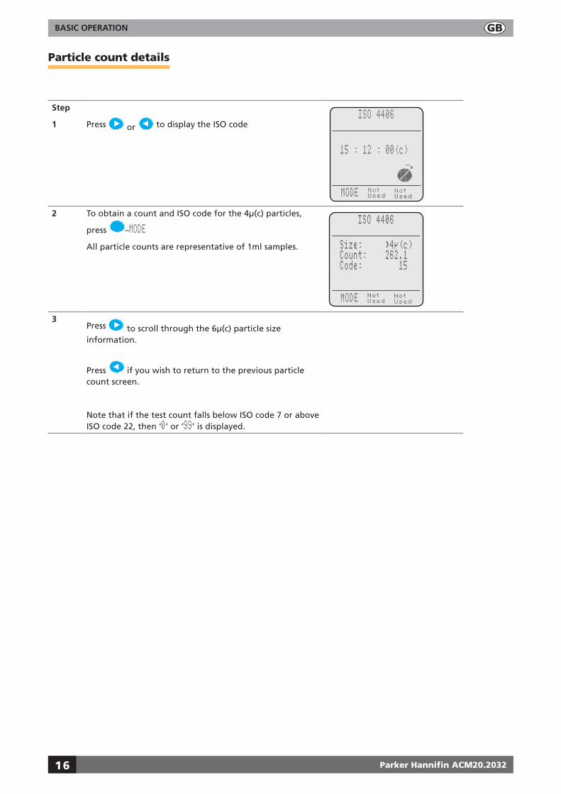
Particle count details
Step
1 Press or to display the ISO code������������
���� ��������������
���������������
2 To obtain a count and ISO code for the 4µ(c) particles,
press –MODEAll particle counts are representative of 1ml samples.
������������
���� ��������������
����������������������������������������������
3Press to scroll through the 6µ(c) particle size information.
Press if you wish to return to the previous particle count screen.
Note that if the test count falls below ISO code 7 or above ISO code 22, then ‘0’ or ‘99’ is displayed.
BASIC OPERATION
Parker Hannifin ACM20.2032
g
17
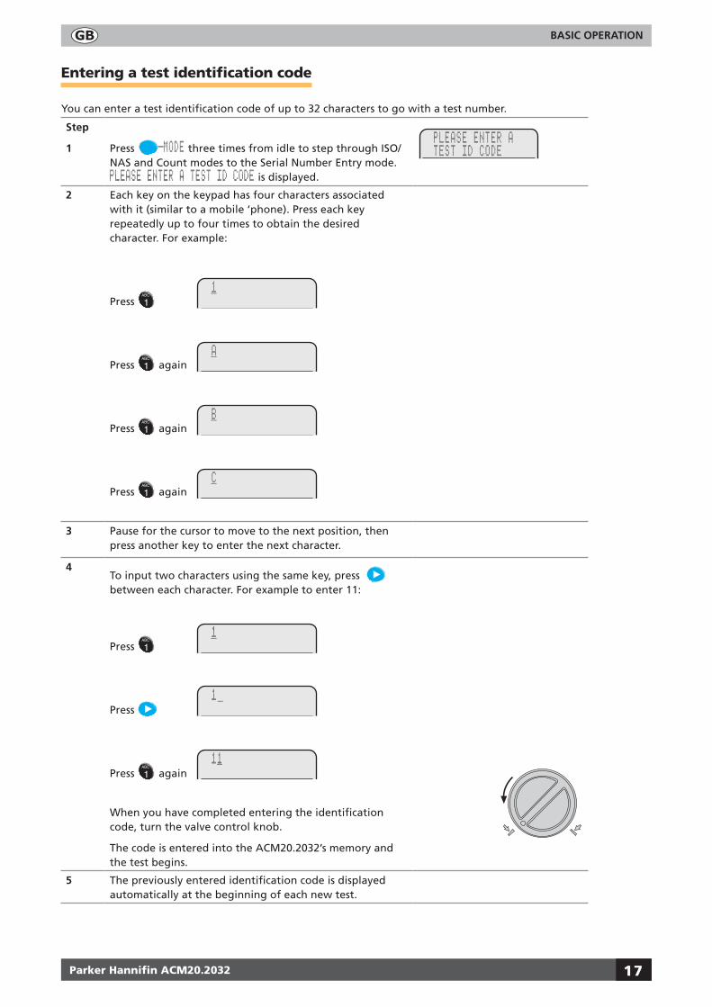
Entering a test identification code
You can enter a test identification code of up to 32 characters to go with a test number.
Step
1 Press –MODE three times from idle to step through ISO/NAS and Count modes to the Serial Number Entry mode. PLEASE ENTER A TEST ID CODE is displayed.
2 Each key on the keypad has four characters associated with it (similar to a mobile ‘phone). Press each key repeatedly up to four times to obtain the desired character. For example:
Press
Press again
Press again
Press again
3 Pause for the cursor to move to the next position, then press another key to enter the next character.
4To input two characters using the same key, press between each character. For example to enter 11:
Press
Press
Press again
When you have completed entering the identification code, turn the valve control knob.
The code is entered into the ACM20.2032’s memory and the test begins.
5 The previously entered identification code is displayed automatically at the beginning of each new test.

BASIC OPERATION
Parker Hannifin ACM20.2032
g
18
6 If the new identification code is unique to the test, simply start typing the new code. The current code is cleared as soon as you enter the first character.
7To change just the last character of the code, press and the cursor moves to the end of the code. Type the new character to replace the previous one.
Press to delete the character just entered if you make a mistake.

BASIC OPERATION
Parker Hannifin ACM20.2032
g
19
Viewing a stored test by ID code or test number
Step
1 Press and hold for two seconds
2Press to select Y
3Press –MODE
Choose S to select a test by serial number, or T to select a test by its test number.
4Press to select T.
5Press –MODE
Enter the test number required.
6Press –MODE to view the test.
7Press or to display the ISO code or ‘% by Volume’ view.
8Press –MODE
To view more results select Y. Select N to return to the idle screen.

BASIC OPERATION
Parker Hannifin ACM20.2032
g
20
Alarm levels
Setting an alarm level
Step
1 Press and hold for two seconds.
2Press to select Y
3 Enter the code level for 4µ above which the alarm is to be triggered.
Press –MODE to repeat this process for 6µ und 14µ.
�����������
4 When all three levels have been entered, the display shows:
If any of the preset alarm levels are triggered during a manual or automatic test, the alarm sound beeps and Alarm flashes on the handset display.
�������������
���� ��������������
��������
Setting up the audible alarm
This allows you to enable or disable the audible alarm. Note that this function reverts to ‘On’ each time the ACM20.2032 is turned off.
1Press and hold for two seconds.
2Press to select Y to enable the alarm
Press to select N to silence the alarm.
���������������������������
3Press –MODE to continue.
BASIC OPERATION
Parker Hannifin ACM20.2032
g
21
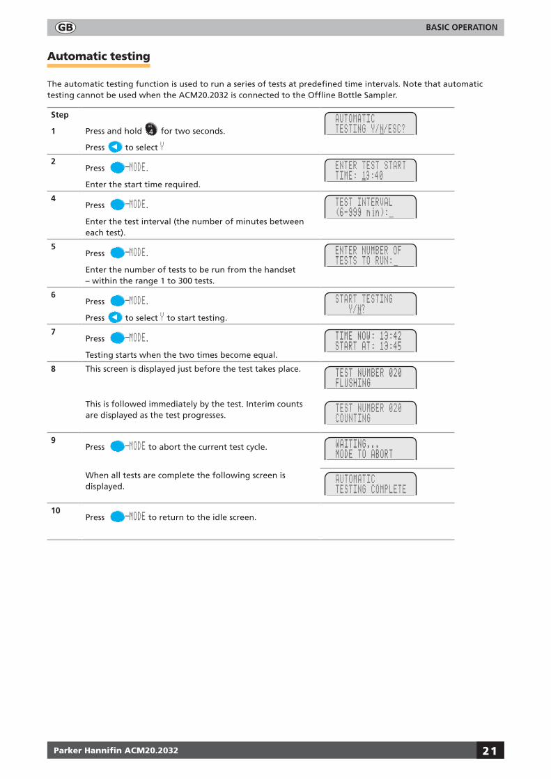
Automatic testing
The automatic testing function is used to run a series of tests at predefined time intervals. Note that automatic testing cannot be used when the ACM20.2032 is connected to the Offline Bottle Sampler.
Step
1 Press and hold for two seconds.
Press to select Y2
Press –MODE.
Enter the start time required.
4Press –MODE.
Enter the test interval (the number of minutes between each test).
5Press –MODE.
Enter the number of tests to be run from the handset – within the range 1 to 300 tests.
6Press –MODE.
Press to select Y to start testing.
7Press –MODE.
Testing starts when the two times become equal.
8 This screen is displayed just before the test takes place.
This is followed immediately by the test. Interim counts are displayed as the test progresses.
9Press –MODE to abort the current test cycle.
When all tests are complete the following screen is displayed.
10Press –MODE to return to the idle screen.

BASIC OPERATION
Parker Hannifin ACM20.2032
g
22
Calibration
When switching the unit on, it will check the date as stored in the real-time clock against the date stored as the next calibration due date.
If the date is within four weeks of the calibration due date, then the following message is displayed when the unit is switched on:
�������������������������������
���� ��������������
���������������������
(The example above is for a calibration due date of 22 February 2007)
To ignore the message for now and continue with testing press –MODE
If the unit passes the calibration due date, the following message is displayed when the unit is switched on:
To ignore the message for now and continue with testing press –MODE
Adjusting screen brightness
The ACM20.2032 is supplied with factory default settings for backlight and brightness settings. These settings can be altered using hot key functions as follows:
Press and hold and press to brighten the screen.
Press and hold and press to darken the screen.
Press and hold and press to switch backlighting on.
Press and hold and press to switch backlighting off.
Note: When the LCM20 is switched off, the backlight function is reset. If you still require the backlight when the LCM20 is switched on again, it will need to be reactivated.
Saving screen brightness settings
Once the screen brightness has been set to the required level, you can save the setting by pressing and holding and simultaneously and following the on-screen instructions.

REFERENCE
Parker Hannifin ACM20.2032
g
23
Reference
Interpreting data
Solid contaminants in aviation fuel systems vary in size, shape, form and quantity. The most harmful contaminants are normally between 6 microns and 14 microns. The ISO code is the preferred method of reporting quantity of contaminants.
The ISO code number corresponds to contamination levels pertaining to three sizes.
The first scale number represents the number of particles larger than 4µm(c) per 100 millilitre of fluid, the second number for particles larger than 6µm(c) per 100 milllilitre of fluid and the third number for particles larger than 14µm(c) per 100 millilitre of fluid.
Below is a table of actual results obtained, of contamination within a hydraulic pump endurance test rig.
Particle size No. of particles per 100ml of fuel
4µ
6µ
14µ
21µ
7950100
280500
1500
1700
ISO-Code: 23/19/11
Num
ber o
f par
ticle
s pe
r 100
mill
ilitre
s gr
eate
r tha
n in
dica
ted
size
Particle size, µm
Interpolation is acceptable; extrapolation is not permissible
REFERENCE
Parker Hannifin ACM20.2032
g
24
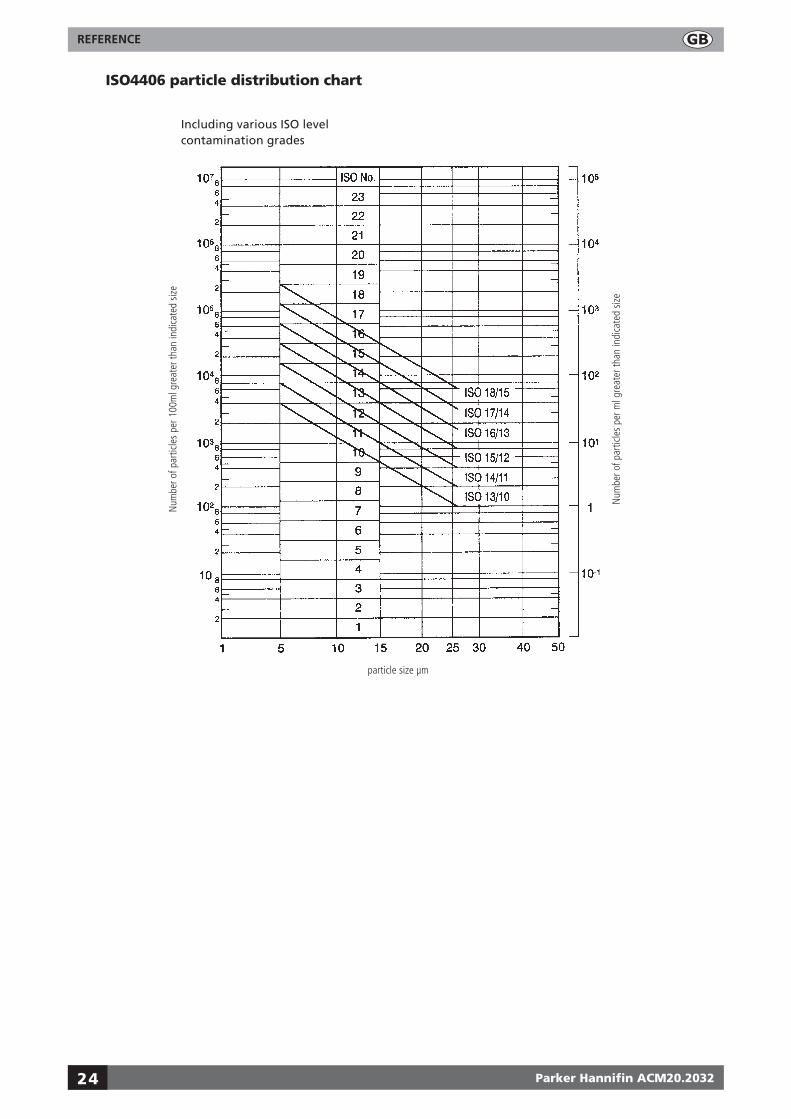
ISO4406 particle distribution chart
Including various ISO level contamination grades
Num
ber o
f par
ticle
s pe
r 100
ml g
reat
er th
an in
dica
ted
size
Num
ber o
f par
ticle
s pe
r ml g
reat
er th
an in
dica
ted
size
particle size µm

REFERENCE
Parker Hannifin ACM20.2032
g
25
ISO contamination numbers
Range number
Number of particles per 100ml
More than Up to and including
1 1 2
2 2 4
3 4 8
4 8 16
5 16 32
6 32 64
7 64 130
8 130 250
9 250 500
10 500 1 × 10³
11 1 × 10³ 2 × 10³
12 2 × 10³ 4 × 10³
13 4 × 10³ 8 × 10³
14 8 × 10³ 16 × 103
15 16 × 103 32 × 103
16 32 × 103 64 × 103
17 64 × 103 130 × 103
18 130 × 103 250 × 103
19 250 × 103 500 × 103
20 500 × 103 1 × 10⁶
21 1 × 10⁶ 2 × 10⁶
22 2 × 10⁶ 4 × 10⁶
23 4 × 10⁶ 8 × 10⁶
24 8 × 10⁶ 16 × 106
For example: code 20/18/13 indicates that there are between 500,000 and 1,000,000 particles larger than 2 microns, and between 130,000 and 250,000 particles larger than 5 microns, and between 4000 and 8000 particles larger than 15 microns.

REFERENCE
Parker Hannifin ACM20.2032
g
26
Suggested acceptable contamination levels for various systems
Target contamination Class to
ISO 4406:1999
Types of system Typical components
15/13/09 Silt sensitive control system wwith very high reliability
Laboratory or aerospace
High performance servovalves
16/14/11 Performance servo and high Pressure long-life systems
e.g. Aircraft machine tools, etc.
Industrial servovalves
17/15/12 Highly sophisticated systems and hydrostatic transmissions
Proportional valves
18/16/13 High quality reliable systems
General machine requirements
Valve and piston pumps/motors
Directional and pressure control valves
19/17/14 General machinery and mobile systems
Medium pressure, medium capacity
Gear pumps/motors
20/18/15 Low pressure heavy industrial systems or applications where long-life is not critical
Flow control valves
Cylinders
23/21/17 Low pressure systems with large clearances Ram pumps
REFERENCE
Parker Hannifin ACM20.2032
g
27
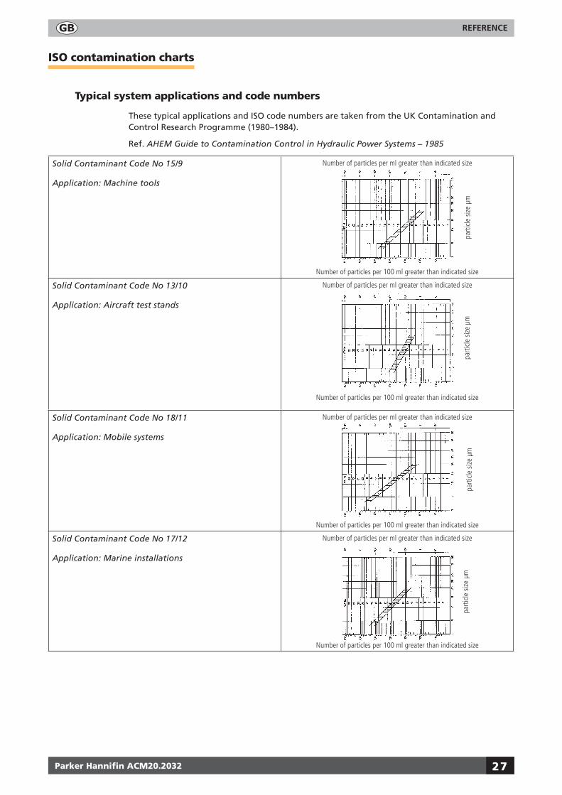
ISO contamination charts
Typical system applications and code numbers
These typical applications and ISO code numbers are taken from the UK Contamination and Control Research Programme (1980–1984).
Ref. AHEM Guide to Contamination Control in Hydraulic Power Systems – 1985
Solid Contaminant Code No 15/9
Application: Machine tools
parti
cle
size
µm
Number of particles per 100 ml greater than indicated size
Number of particles per ml greater than indicated size
Solid Contaminant Code No 13/10
Application: Aircraft test stands
Number of particles per ml greater than indicated size
Number of particles per 100 ml greater than indicated size
parti
cle
size
µm
Solid Contaminant Code No 18/11
Application: Mobile systems
Number of particles per ml greater than indicated size
Number of particles per 100 ml greater than indicated size
parti
cle
size
µm
Solid Contaminant Code No 17/12
Application: Marine installations
Number of particles per ml greater than indicated size
Number of particles per 100 ml greater than indicated size
parti
cle
size
µm

REFERENCE
Parker Hannifin ACM20.2032
g
28
Solid Contaminant Code No 18/13
Applications: Mechanical handling
Number of particles per ml greater than indicated size
Number of particles per 100 ml greater than indicated size
parti
cle
size
µm
Solid Contaminant Code No 16/11
Applications: Injection moulding; Metalworking; Unused commercial-grade oil
Number of particles per ml greater than indicated size
Number of particles per 100 ml greater than indicated size
parti
cle
size
µm

REFERENCE
Parker Hannifin ACM20.2032
g
29
Hydraulic circuit diagram
Note: This is a diagrammatic representation only
1 Monitor block
2 Laser diode
3 Optical scanner
4 Changeover valve
5 Dual direction syringe pump
6 Flow probe device
SYSTEM 20 SENSOR
Direction of flow
Logic diagram
Unobstructed lightcalculator
Comparator
CounterCounter Counter Counter Counter Counter
Comparator Comparator
Count to codeconverter
Switch
Display Memory PC
Area calculator
Reference voltagegenerator
Comparator Comparator Comparator
Optical Scanner

REFERENCE
Parker Hannifin ACM20.2032
g
30
Measurement accuracy
Calibration
Every monitor is individually calibrated using an accurately determined gravimetric level of test dust media.
Each channel within the instrument is adjusted to read the number of particles in a prescribed size range as specified in ISO procedures, thus guaranteeing calibration accuracy.
Repeatability
The ACM20.2032 measures and quantifies individual particles using advanced electronics and laser technology to ensure a high degree of repeatability.
Repeatability is typically better than 5%.
Connectors and Serial interface
Top panel (cover off)
ON/OFF BATTERYCHARGER
DATACABLE
Handsetcable gland
WARNINGTHE BATTERY CHARGER AND DATA
CABLE ARE NOT TO BE USED IN THEHAZARDOUS AREA
The Data Cable (supplied) is a flying lead connected to a 9-way RS232 connector for a PC. It is used to download test data stored in the unit.
(See the ParSmart software package for data management information.)
RS 232

REFERENCE
Parker Hannifin ACM20.2032
g
31
Diagnostic codes
Explanations of ACM20.2032 diagnostic codes are given in the following table.
Diagnostic 1
1A. At beginning of test (the first two segments showing)
Fuel is too dark or it is cloudy. Check sample of fuel visually. This can be done as follows:
Dark fuels: Wet your thumb and forefinger in the fuel and press together. Release and look at your thumb. If you can see through the film of fuel it should work in the ACM20.2032. If you cannot, then you may have problems.
Emulsions: Put sample in a clear container and hold up to the light. This will show cloudy or clear. If cloudy, check the type of fuel and change until the fuel is clean. Then retry ACM20.2032.
1B. at the end of the test
Unstable fluid opacity may be caused by aeration, water sludge or an amount of cold fuel passing through ACM20.2032
Allow machine to work up to operating temperature before performing condition monitoring. Run tests with a stable system and ensure that a minimum line pressure of 2 bar is available at the monitor to reduce the possibility of aeration.
Diagnostic 2
The changeover valve and syringe pump are out of phase
a. Control knob turned, either before monitor switched on, before valve symbol displayed on handset or during a test
b. Time taken to turn valve fully to next position is too long (20 seconds)
c. Microswitch setting fault.
a. Switch off the monitor, then switch on and wait for monitor to reset its position (diagnostic screen 6 is displayed). Start next test when valve symbol is displayed on handset.
b. Return to Parker Hannifin for repair
c. Return to Parker for repair.
Diagnostic 3
Uncontrolled power down
a. Battery power too low. Battery level warning ignored
b. Internal electrical fault
a. Charge the unit (outside the hazardous area) b. Return to Parker Hannifin for repair
Diagnostic 4
Insufficient flow rate of fuel from P1 hose into monitor block to fill syringe pump.
Results are suspect and not made available.
a. Inadequate differential pressure across P1 and P2 connections to provide sufficient bypass flow.
b. Air lock in monitor block or blockage in bypass hoses.
i) Select smaller sized sensor
ii) Use a Single Point Sampler connected to P1 (see the Parker Hannifin catalogue for details). Purge by using system pressure with P2 hose disconnected from system.

REFERENCE
Parker Hannifin ACM20.2032
g
32
Diagnostic 5
Test time too short or too long.
Results are suspect and are not made available.
a. Malfunction of Opto-Tacho control, causing flow to stop before particle counting phase completed. Pump drive slipping or failed.
b. DP (Differential Pressure) too high due to lack of control of flow through ACM20.2032.
a. Care should be taken to allow fuel to discharge safely and should only be performed by a competent operator.
Re-test and if fault reoccurs, return monitor to Parker Hannifin for repair.
b. Use SPS (Single Point Sampler) or sensor to control flow through ACM20.2032.
Diagnostic 6
��������������������������
Unit trying to reset from last error
Displayed after switching on, while monitor is resetting itself from the previous error condition.
Leave it alone until it has reset.
If it does not reset, or switches itself off, contact Parker Hannifin.
Diagnostic 7 and above
These are faults which can only be rectified by Parker Hannifin and are normally software related
Displayed if the monitor block has reached a temperature above 60°C.
Remove ACM20.2032 from system connections.
Allow to cool down.
If unit does not reset, contact Parker Hannifin.
Low battery
�������������
Battery low. Recharge unit (only outside of hazardous area with the unit switched off).
Battery too low to complete a measurement. Recharge unit (only outside of hazardous area with the unit switched off).

REFERENCE
Parker Hannifin ACM20.2032
g
33
Technical specifications
Construction Unit: stainless steel
Carrying case: ABS
Hand-held display: ABS
Keypad: polyester membrane
Mechanical components Brass, plated steel, stainless steel and aluminium
Seals Viton
Hoses Nylon (Kevlar braided microbore)
Hose length Fluid connection hose: 1.2 metres (1 metre extensions can be used)
Hand-held display cable length: 1 metre
Flow rate Up to 400 l/min (System 20 sensors)
Higher with Single Point Sampler – consult Parker
Max. working pressure Up to 420 bar (System 20 sensors)
Fluid compatibility Aviation fuel. For other fluids consult Parker
Power Internal rechargeable battery
Note: ONLY to be charged outside of the hazardous area, with the unit switched off
Fuse 1.25A fast blow fuse included for overload protection
Return to Parker Hannifin if fuse is blown
ACM20.2032 technology Unique optical scanning system
Size, measurement and ranges 4+, 6+, 14+, 21+, 25+ and 30+ micron(c)
Analysis range ISO 7 to 22 inclusive
Calibration Each unit is individually tested and calibrated in accordance with ISO procedures
Repeatability/Accuracy Better than 5% (typical)
Viscosity range 2–100 centistokes (500cSt with SPS)
Oil temp. range +5°C to +80°C
Operating temp. range +5°C to +40°C
Test completion time 2 minutes
Computer Interface RS232 at 9600 baud
Weight ACM20.2032: 15kg, Carrying case: 8.5kg
Commissioning kit Includes: ParSmart Downloader software plus cable
12Vdc charger and cable
UK, US and Euro power plug and cable
Millipore adaptor assembly

REFERENCE
Parker Hannifin ACM20.2032
g
34
Top, front and rear views of the unit

REFERENCE
Parker Hannifin ACM20.2032
g
35
Battery charger B.84.647
LED colours and their significance
LED colour on charger Mode Comment
Yellow Battery not connected Output form charger 21V
Yellow Charger initialization Initialization lasts a few seconds
Orange/Red Fast charge 1.8A for two hours maximum voltage sensed
Green with Yellow flash Top-up charge 270mA, timed
Green Trickle charge 100mA for 24 hours, then disconnect
Changing Orange/Red to Green
Fault 100mA max output
Battery specification
Type NiMH (Nickel Metal Hydride)
Charging conditions Via supplied charger only. Fast charge, top-up and trickle charge provided
Temperature range Storage: –20 to 35°C
Discharge operation: –20 to 50°C
Fast charge: 10 to 45°C
Other charge: 0 to 45°C
Life expectancy >500 cycles (IEC standard) before a gradual loss of capacity.
It is recommended that the battery undergoes a full discharge/charge cycle every 3 months.
Shelf life 3 years

REFERENCE
Parker Hannifin ACM20.2032
g
36
Ordering information
Part number Description Qty
ACM20.2032 ACM20 for Aviation fuels only, certified for Zone 2 use
P.843066 Spare case
B.84.816 ParSmart Downloader system monitoring data download
B.84.650 Cable link package
SPS.2021 Single Point Sampler
B.84.647 Battery charger
System 20 sensors
Industrial Sensors – Sizes 0, 1 and 2
Part number Size Flow range Thread Qty
STI.0144.100 0 6–25 l/min G 3–8
STI.0344.100 0 0.5–7 US GPM 3–4 UNF
STI.1144.100 1 20–100 l/min G 3–4
STI.1344.100 1 5–26 US GPM SAE 1 3–16 – 12UN-2B
STI.2144.100 2 80–380 l/min G1 1–4
STI.2344.100 2 21–100 US GPM SAE 1 5–8 – 12UN-2B
Operation checklist
Always ensure:
n Sensors are installed correctly
n Sensor connectors are correctly tightened
n There is adequate fuel flow
n Steady state pressure conditions
n Trend monitoring is performed under similar working conditions
n Hoses are correctly stowed to avoid fuel spillage
n ACM20.2032 is handled with care – it is an instrumentation product
n Spares are reordered in advance
n The ACM20.2032 is calibrated according to Parker recommendations.

FILTRATION GROUP TECHNICAL SALES & SERvICE LOCATIONSParker Hannifin (UK) LtdFilter Division EuropeShaw Cross Business ParkDewsbury, West YorkshireWF12 7RD, UKPhone: +44 (0)1924 487000Fax: +44 (0)1924 487001Email: [email protected]
Parker Hannifin (UK) LtdFilter Division EuropeCondition Monitoring CentreBrunel Way, Thetford, NorfolkIP24 1HP, UKPhone: +44 (0)1842 763299Fax: +44 (0)1842 756300Email: [email protected]
Parker Hannifin OyFilter Division EuropeSalmentie 260FIN - 31700 Urjala As, FinlandPhone: +358 20 7532 500Fax: +358 20 7532 501Email: [email protected]
Parker Filtration BvFilter Division EuropeStieltjesweg 86827 BV Arnhem, The NetherlandsPhone: +31 (0)26 3760376Fax: +31 (0)26 3643620
Email: [email protected]
www.parker.com/cmc
European Product Information Centre (24-hour): + 00800 27 27 5374
Email: [email protected]
© Parker Hannifin, 2007. P.849132, issue 3
WORLDWIDE SALES LOCATIONSArgentina ........................ +54 (11) 4752 4129Australia.......................... +61 (2) 9 634 777Austria ............................ +43 2622 23501-0Belgium ........................... +32 (67) 280900Brazil ............................... +55 12 3955 1000Canada ............................ +1 800 272 7537Central & South America/ Caribbean ........................ +1 305 470 8800China............................... +86 (21) 6445 9339Czech Republic ................ +42 0 2 830 85 221Denmark ......................... +45 0 43 56 04 00Finland ............................ +358 20 7532 500France ............................. +33 04 50 25 8025Germany ......................... +49 (0) 2131 40160Hong Kong ...................... +852 (2) 428 8008Hungary .......................... +36 (1) 252 8137India ................................ +91 55907081 85Italy ................................. +39 02 451921Japan .............................. +81 3 6408 3900 Jordan ............................. +(962) (6) 810679Korea ............................... +82 31 379 2200Malaysia .......................... +62 811 179135Mexico ............................ +1 800 272 7537Netherlands ..................... +31 0 541 585000New Zealand ................... +64 (9) 573 1523Norway ........................... +47 64 91 1000Philippines ....................... +63 34 4323 779Poland ............................. +48 22 5732 400Singapore ........................ +65 688 76300South Africa ..................... +27 (11) 961 0700Spain ............................... +34 (91) 675 7300Sweden ........................... +46 8 5979 5000Switzerland ..................... +41 31 917 1850 Taiwan............................. +886 2 2298 8987Thailand .......................... +662 693 3304United Arab Emirates ...... +971 2 6788587United Kingdom .............. +44 1926 317878USA ................................. +1 800 272 7537Venezuela ........................ +58 212 238 54 22
Parker Hannifin Corporation
The Ch ice is
Perfectly Clear
Distributor