Embed Size (px)
Citation preview
ADVISORY CIRCULAR 43-16A
AVIATION MAINTENANCE ALERTS
ALERT
NUMBER 307
FEBRUARY
2004
CONTENTS
AIRPLANES BEECH ........................................................................................................................................1 CESSNA ......................................................................................................................................1 GULFSTREAM...........................................................................................................................4 LAKE...........................................................................................................................................4 PIPER...........................................................................................................................................5
ACCESSORIES CHAFED HYDRAULIC LINES.................................................................................................5 FUEL CAPS FOR GENERAL AVIATION AIRPLANES.........................................................6
AIR NOTES ELECTRONIC VERSION OF FAA FORM 8010-4, MALFUNCTION OR DEFECT REPORT ............................................................................6 PAPER COPY OF FAA FORM 8010-4, MALFUNCTION OR DEFECT REPORT................7 SERVICE DIFFICULTY REPORTING PROGRAM ................................................................7 IF YOU WANT TO CONTACT US...........................................................................................8 AVIATION SERVICE DIFFICULTY REPORTS .....................................................................8
February 2004 AC 43-16A
Page 1
U.S. DEPARTMENT OF TRANSPORTATION FEDERAL AVIATION ADMINISTRATION
WASHINGTON, DC 20590
AVIATION MAINTENANCE ALERTS The Aviation Maintenance Alerts provide a common communication channel through which the aviation community can economically interchange service experience and thereby cooperate in the improvement of aeronautical product durability, reliability, and safety. This publication is prepared from information submitted by those who operate and maintain civil aeronautical products. The contents include items that have been reported as significant, but which have not been evaluated fully by the time the material went to press. As additional facts such as cause and corrective action are identified, the data will be published in subsequent issues of the Alerts. This procedure gives Alerts’ readers prompt notice of conditions reported via Malfunction or Defect Reports. Your comments and suggestions for improvement are always welcome. Send to: FAA; ATTN: Aviation Data Systems Branch (AFS-620); P.O. Box 25082; Oklahoma City, OK 73125-5029.
AIRPLANES BEECH
Beech; Model B200; King Air; Unsecured Main Landing Gear Wiring Harness; ATA 3260
During an approach for landing, the pilot attempted to extend the landing gear; however, the left main landing gear down-and-locked indicator did not illuminate. He declared an emergency and made a safe landing.
The technician discovered the ty-wrap from the left main landing gear drag brace, which secures the wiring bundle, was missing. He speculated that when the pilot retracted the gear, the inboard gear door-actuating roller caught the wire bundle and broke the down-and-locked circuit wire.
Part total time: 7,891 hours.
Beech; Model 1900C; Airliner; Failure of the Air Stair Door; ATA 5210
After a landing, the flightcrew could not open the forward air stair door. They reported the interior air stair door handle was inoperative.
The technician discovered the square handle shaft had sheared and was even with the base of the handle. He replaced the interior door handle assembly (P/N 101-384096-1).
According to the submitter, this is the fifth failure of this part number assembly in their fleet in the last year.
Part total time: 3,403 hours.
CESSNA Cessna; Series 100 and 200; Defective Fuel Hoses (P/N S1495-6); ATA 2820
The Airframe and Propulsion and Services Wichita Aircraft Certification Office, ACE-118W, located in Wichita, Kansas, submitted the following article. (This article is published as it was received.)
Recently the FAA was advised that a current production Cessna single engine airplane experienced a fuel leak at the flexible fuel line connection between the wing fuel tank and the fuselage fuel line connection. The suspect hose is identified in the applicable airplane parts manual as S1495-6, which
AC 43-16A February 2004
Page 2
Cessna has used for many years on all single engine airplane products. Cessna has confirmed that two of their fuel hose suppliers provided hose material to the Cessna Aircraft Co. on 5/13/99 and 12/2/99 that may not meet their specification S1495. Therefore, the FAA recommends that owners, operators and inspection personnel of Cessna single engine airplanes that may have had a new Cessna Specification S1495-6 fuel hose installed that was obtained/shipped from Cessna Parts Distribution between May 1999 and November 2000 inspect the hoses for rapid age wear. This inspection is recommended to apply to new airplanes with Airworthiness Certificates dated from May 1999 through June 2000 as well as those that have field installed hoses that may have been shipped from Cessna Parts Distribution between May 1999 and November 2000.
If any of the S1495-6 hose connections have identification markings that indicate Dayco series 7095, any Boston identification, or any identification other than Dayco L3 or B7, remove all S1495-6 hose connections in the LH and RH wingroot and replace with new S1495-6 hose having Dayco B706 identification markings. Dayco 6L3 was an approved hose as well, but is no longer utilized under the S1495 specification.
If identification markings are unreadable or not present, inspect all S1495-6 hose connections in the LH and RH wing root areas for evidence of hardening, as described below. If any S1495-6 hose connections exhibit evidence of hardening, remove all of the hose connections in the LH and RH wing root areas and replace with new S1495-6 hose having Dayco B706 identification markings.
Hardening can be determined by pinching the hose between one’s thumb and forefinger. Hoses that do not compress or are not resilient can be considered hardened and should be replaced.
The FAA may publish additional advisory and possibly regulatory information applicable to the Cessna S1495 hose installation depending on the results of a current field survey. However, it has been determined that enough time has elapsed since the suspect hoses were shipped from Cessna that routine maintenance might have already encouraged the replacement of some suspect hoses either in the fleet or available from spares support facilities in the field. Therefore, the FAA is publishing this Alerts Article to advise owners, operators, and repair facilities that any remaining S1495 hose shipped from Cessna between May 1999 and November 2000 and possibly installed should be removed from service and any remaining inventory not identified as Dayco B706 should be removed from spares inventory.
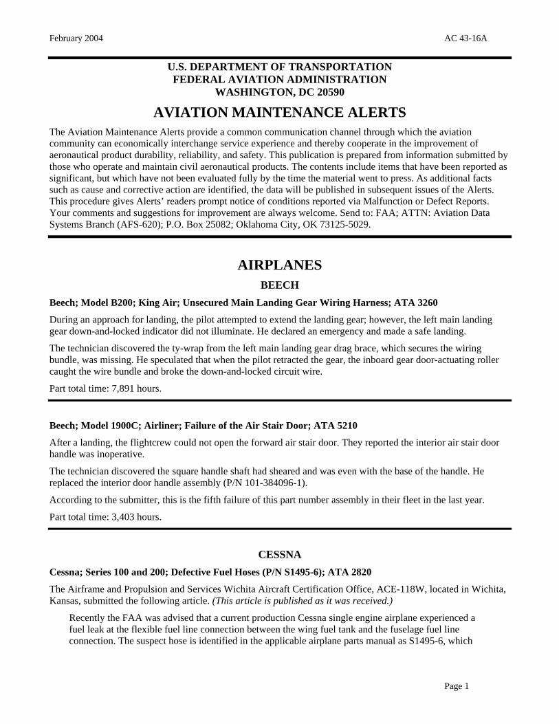
Cessna; Model 402C; Businessliner; Trailing Edge Flap Bellcrank Bracket Failure; ATA 2750
On approach for landing, the pilot extended the flaps 10 degrees. The aircraft immediately rolled right approximately 30 degrees. He retracted the flaps and landed the aircraft without incident.
The technician stated that the right flap inboard actuating bellcrank bracket (P/N 5115538-2) failed and caused the flap bellcrank (P/N 0822275-55) to fail. (Refer to the illustrations.)
February 2004 AC 43-16A
Page 3
Part total time: 9,284 hours.
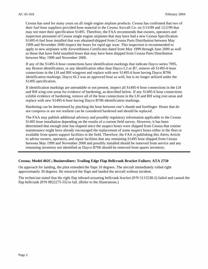
Cessna; Model 421C; Golden Eagle III; Damaged Engine Exhaust Pipe Riser; ATA 7810
While in IFR flight, the pilot reported the loss of manifold pressure and exhaust gas temperature instrumentation readings. However, manifold pressure stabilized at lower than normal readings. He made a precautionary landing at the closest airport.
The technician pressure checked the exhaust system and found a 2-½ inch hole at the exhaust data plate on the left inside exhaust riser (P/N 8294-3). The damage was not visible without a mirror.
The submitter believed the cause of this incident was due to uneven heating and cooling of the pipe under the data plate, which is welded to the pipe. (Refer to the illustration.)
AC 43-16A February 2004
Page 4
The submitter suggested welding the data plate on the outside of the exhaust pipe to allow easier inspections. He also suggested eliminating the data plate and electronically etch information on the riser.
Part total time unknown.
GULFSTREAM Gulfstream; Model GV; Skydrol Accumulation Inside Oxygen Access Panel; ATA 2910
The technician discovered the oxygen access panel on the right side of the fuselage had a noticeable amount of Skydrol-500 accumulated inside the access door of the O-2 service panel.
The technician determined the fluid was coming from the emergency landing gear air-release valve vent port. This was due to leakage of the hyd/air shuttle valve for the left hand landing gear side stay actuator. This vent is forward of the O-2 service panel.
According to the submitter, Skydrol-500B-4 MSDS states, “…materials to avoid exposure to strong oxidizing agents.”
Part total time unknown.
LAKE Lake; Model LA-4; Corroded Rivets on Elevator Pushrod End Fitting; ATA 2730
The Atlanta Aircraft Certification Office, ACE-115A, located in Atlanta, Georgia, submitted the following
article. (This article is published as it was received.)
On November 27, 2003, the Australian Civil Aviation Safety Authority’s Airworthiness Directive (AD) LA-4/10, Amendment 1, became effective. The amendment of this AD was the result of a failure of the elevator push rod on an Australian registered LA-4. The rivets holding the end fitting on the tube had corroded and failed which allowed the end fitting to fall out. There was also corrosion found on the tube. This failure caused a loss of control and subsequent aircraft damage due to a hard landing.
February 2004 AC 43-16A
Page 5
A search of the FAA Service Difficulty Reporting Program data base revealed six additional reports citing corrosion of the control system components. These reports include the aileron control system, rudder control system, and elevator control system. It is recommended that all control system components of all Lake series airplanes be inspected for corrosion every 100 hours or every 12 months.
Part total time unknown.
PIPER Piper; Model PA-24-260; Comanche; Cracked Rudder Hinge Bracket; ATA 5540
During required maintenance, the technician removed the rudder and found a crack in the middle rudder hinge bracket (P/N 20707-03) on the vertical fin at the hinge-bearing hole.
According to the submitter, the crack was not visible unless the rudder was removed.
Part total time: 5,500 hours.
Piper; Model PA 28-161; Warrior II; Cracked Stub Axle and Oleo Piston Assembly; ATA 3213
While investigating an oleo fluid leak, the technician found three ¼-inch cracks running horizontally across the outboard facing area of the left main gear oleo piston assembly (P/N 78738-802). The cracks were located 7 inches and 9 inches up from the base. They were not visible until there were complete strut extensions. The hollow tube contained fluid, which suggests it had been cracked for sometime.
The submitter recommended inspecting this area of the landing gear on 100-hour intervals. This is especially important on school aircraft with high cycles.
Part total time: 10,410 hours.
ACCESSORIES CHAFED HYDRAULIC LINES
ALL AIRCRAFT MODELS WITH HYDRAULIC SYSTEMS The Airframe and Propulsion and Services Wichita Aircraft Certification Office, ACE-118W, located in Wichita, Kansas, submitted the following article. (This article is published as it was received.)
Service Difficulty Reports are being received of leaking hydraulic tubing caused by chafing from wiring, and nearby unprotected equipment and structure on aircraft. In one case, a hydraulic tube located in the aft equipment bay of a Learjet Model 35 was chafed through by an electrical power wire. The chafing had opened a pinhole in the hydraulic line and also removed the insulation from the wiring. This allowed a fine mist of fluid and a small arc to occur at the same time and place, resulting in a localized fire. In another case involving a Cessna Model 550, a hydraulic tube was chafed by a supply duct to the cabin air conditioning system. This resulted in failures of both the hydraulic line and the cabin air supply duct. The failed hydraulic line released fluid into the aircraft air conditioning system exposing the crew and passengers to misting hydraulic fluid.
It is recommended that, when performing maintenance in areas where hydraulic tubes are installed, all aircraft owners, operators, and maintenance personnel should inspect for adequate clearance between the hydraulic tubes and surrounding wiring, equipment, and structure. Particular attention should be
AC 43-16A February 2004
Page 6
applied to the inspection of aircraft with aftermarket modifications or major repairs. Any noted occurrence of hydraulic tubing with inadequate clearance or with evidence of wear from wiring, equipment, or surrounding structure should be repaired, and adequate clearance provided.
FUEL CAPS FOR GENERAL AVIATION AIRPLANES The Airframe and Propulsion and Services Wichita Aircraft Certification Office, ACE-118W, located in Wichita, Kansas, submitted the following article. (This article is published as it was received.)
The FAA recently published an Alerts article (December 2003) applicable to the correct positioning of fuel caps, due to an accident on an Ercoupe Model 415. The FAA has since received a Safety Recommendation concerning a Cessna 182 accident, possibly related to the incorrect placement and closure of an aftermarket fuel cap, which resulted in fuel being siphoned from the wing fuel tank. It appears that some pilots may not be giving sufficient attention to proper installation of fuel caps prior to flight.
The Safety Recommendation requested reference marking on the fuel cap be added to allow a person to visually determine if the caps are properly locked in place on all airplanes equipped with this type of aftermarket fuel cap. The fuel cap in question was a screw-type cap, similar to many current automotive fuel tank, oil service and lawnmower applications. The FAA believes that this standard type of fuel cap and the method of installation do not warrant adding reference marking. Standard, typical procedures such as those required for common everyday consumer products should be adequate to preclude improper fuel cap installation.
The FAA encourages aircraft pilots, fuel service personnel and mechanics to maintain vigilance during preflight, servicing, minor and major maintenance and inspection of all aircraft fuel systems and especially the fuel cap installation on all airplanes.
AIR NOTES ELECTRONIC VERSION OF FAA FORM 8010-4, MALFUNCTION OR DEFECT REPORT
One of the recent improvements to the Flight Standards Service Aviation Information Internet web site is the inclusion of FAA Form 8010-4, Malfunction or Defect Report. This web site is still under construction and further changes will be made; however, the site is now active, usable, and contains a great deal of information.
Various electronic versions of this form have been used in the past; however, this new electronic version is more user friendly and replaces all other versions. You can complete the form online and submit the information electronically. The form is used for all aircraft except certificated air carriers who are provided a different electronic form. The Internet address is: http://av-info.faa.gov/sdrx
When the page opens, select “M or D Submission Form” and, when complete, use the “Add Service Difficulty Report” button at the top left to send the form. Many of you have inquired about this service. It is now available, and we encourage everyone to use this format when submitting aviation, service-related information.
February 2004 AC 43-16A
Page 7
PAPER COPY OF FAA FORM 8010-4, MALFUNCTION OR DEFECT REPORT In the past, the last two pages of the Alerts contained a paper copy of FAA Form 8010-4, Malfunction or Defect Report. To meet the requirements of *Section 508, this form will no longer be published in the Alerts; however, the form is available on the Internet at: http://forms.faa.gov/forms/faa8010-4.pdf. You can still download and complete the form as you have in the past.
*Section 508 was enacted to eliminate barriers in information technology, to make available new opportunities for people with disabilities, and to encourage development of technologies that will help achieve these goals.
SERVICE DIFFICULTY REPORTING PROGRAM The objective of the Service Difficulty Reporting (SDR) Program is to achieve prompt and appropriate correction of conditions adversely affecting continued airworthiness of aeronautical products fleet wide. The SDR program is an exchange of information and a method of communication between the FAA and the aviation community concerning inservice problems.
A report should be filed whenever a system, component, or part of an aircraft, powerplant, propeller, or appliance fails to function in a normal or usual manner. In addition, if a system, component, or part of an aircraft, powerplant, propeller, or appliance has a flaw or imperfection which impairs, or which may impair its future function, it is considered defective and should be reported under the program.
These reports are known by a variety of names: Service Difficulty Reports (SDR), Malfunction or Defect Reports (M or D) and Maintenance Difficulty Reports (MDR).
The collection, collation, analysis of data, and the rapid dissemination of mechanical discrepancies, alerts, and trend information to the appropriate segments of the FAA and the aviation community provides an effective and economical method of ensuring future aviation safety.
The FAA analyzes SDR data for safety implications and reviews the data to identify possible trends that may not be apparent regionally or to individual operators. As a result of this review, the FAA may disseminate safety information to a particular section of the aviation community. The FAA also may adopt new regulations or issue airworthiness directives (AD’s) to address a specific problem.
The primary source of SDR’s are certificate holders operating under Parts 121, 125, 135, 145 of the Federal Aviation Regulations, and the general aviation community which voluntarily submit records. FAA Aviation Safety Inspectors may also report service difficulty information when they conduct routine aircraft and maintenance surveillance as well as accident and incident investigations.
The SDR data base contains records dating back to 1974. Reports may be submitted on the Internet through an active data entry form or on hard copy. The electronic data entry form is in the Flight Standards Aviation web site. The URL is: http://av-info.faa.gov/. A public search/query tool is also available on this same web site. This tool has provisions for printing reports or downloading data.
At the current time we are receiving approximately 45,000 records per year.
Point of contact is: John Jackson Service Difficulty Reporting System Program Manager Aviation Data Systems Branch, AFS-620 P.O. Box 25082 Oklahoma City, OK 73125
Telephone: (405) 954-6486 E-mail: mailto:[email protected]
AC 43-16A February 2004
Page 8
IF YOU WANT TO CONTACT US We welcome your comments, suggestions, and questions. You may use any of the following means of communication to submit reports concerning aviation-related occurrences.
Editor: Isaac Williams (405) 954-6488 FAX: (405) 954-4570 or (405) 954-4655
Mailing address: FAA, ATTN: AFS-620 ALERTS, P.O. Box 25082, Oklahoma City, OK 73125-5029
You can access current and back issues of this publication from the internet at: http://av-info.faa.gov/. Select the General Aviation Airworthiness Alerts heading.
AVIATION SERVICE DIFFICULTY REPORTS The following are abbreviated reports submitted between January 1, 2004, and January 21, 2004, which have been entered into the FAA Service Difficulty Reporting (SDR) System data base. This is not an all inclusive listing of Service Difficulty Reports. For more information, contact the FAA, Regulatory Support Division, Aviation Data Systems Branch, AFS-620, located in Oklahoma City, Oklahoma. The mailing address is:
FAA Aviation Data Systems Branch, AFS-620 PO Box 25082 Oklahoma City, OK 73125
To retrieve the complete report, click on the Control Number located in each report. These reports contain raw data that has not been edited. Also, because these reports contain raw data, the pages containing the raw data are not numbered.
If you require further detail please contact AFS-620 at the address above.
Federal Aviation Administration Service Difficulty Report Data
Sorted by aircraft make and model then engine make and model. This report derives from unverified information submitted by the aviation community without FAA review for accuracy. Control Number Aircraft Make Engine Make Component Make Part Name Part Condition
Difficulty Date Aircraft Model Engine Model Component Model Part Number Part Location
CA031107016 AIRTRC PWA EYEBOLT CRACKED
11/7/2003 AT802 PT6* AN4730A HORIZONTAL STAB
(CAN) DURING MPI INSPECTION OF THE HORIZONTAL STABILIZER STRUT ATTACH EYEBOLTS, A CRACK APPROXIMATELY .1875 INCH IN LENGTH WAS NOTED. ALL EYEBOLTS WILL BE REPLACED PRIOR TO THE AIRCRAFT BEING RETURNED TO SERVICE.
CA031107015 AIRTRC PWA EYEBOLT CRACKED
11/7/2003 AT802 PT6A67A AN4730A HORIZONTAL STAB
(CAN) DURING ANNUAL INSPECTION THE HORIZONTAL STAB STRUT ATTACH EYEBOLTS WERE REMOVED FOR INSPECTION. DURING MPI THERE WAS A CRACK OF APPROXIMATELY .3125 INCH IN LENGTH NOTED AT THE RADIUS. ALL OTHER AIRCRAFT IN OUR FLEET WILL BE INSPECTED. THE EYEBOLTS WILL BE REPLACED WITH NEW PRIOR TO THE AIRCRAFT BEING RETURNED TO SERVICE. I WOULD LIKE TO SUGGEST THAT ALL OPERATORS OF THIS AIRCRAFT TYPE INSPECT THE EYEBOLTS FOR CRACK INDICATIONS.
AUS20031142 AMTR CONT RACK FAULTY
5/6/2003 RV8 TSIO550B 552541 AUTOPILOT RACK
(AUS) AUTOPILOT RACK FAULTY. RACK WAS TOO LONG FOR COMPUTER AND THE PINS WOULD NOT MATE CORRECTLY. RACK WAS A NEW ITEM.
AUS20031200 AMTR ROTAX FLYING WIRE FAILED
9/21/2003 RV8 ROTAX912 WING
(AUS) FLYING WIRE BROKEN. INVESTIGATION FOUND FLYING WIRES WERE UNDERSIZE. AIRCRAFT IS AMATEUR BUILT. PERSONNEL/MAINTENANCE ERROR. UNAPPROVED PART.
AUS20031242 AYRES GARRTT OIL COOLER SPLIT
12/7/2003 S2RT34NORMAL TPE331* 10717C ENGINE
(AUS) ENGINE OIL COOLER SPLIT ALONG WELD LOCATED AT THE OPPOSITE END TO THE FITTINGS. COMPLETE LOSS OF ENGINE OIL.
AUS20031218 BEECH PWA CAP CRACKED
11/25/2003 1900C PT6A65B ACTUATOR
(AUS) NOSE LANDING GEAR ACTUATOR END CAP CRACKED.
AUS20031256 BEECH LYC VALVE GUIDE WORN
12/10/2003 76 LO360A1G6 74230 NR 1 CYLINDER
(AUS) NR 1 CYLINDER EXHAUST VALVE AND VALVE GUIDE WORN EXCESSIVELY. VALVE NOT SEATING CORRECTLY. FOUND DURING INSPECTION IAW AD/ENG/4 AMDT8.
CA031001004 BEECH PWA FUEL TANK CONTAMINATED
9/24/2003 A100 PT6A28 AFT MIDDLE
(CAN) WHILE INSPECTING THE INSIDE OF THE BLADDER TANKS FOR LOOSE PATCHES BECAUSE OF LOOSE PATCHES FOUND ON ANOTHER AIRCRAFT. MAINTENANCE FOUND A BABY SLEEPER INSIDE AFT MIDDLE FUEL
TANK. THIS AIRCRAFT CAME INTO THE FLEET 3 YEARS AGO AND AS THIS COMPANY DOES NOT USE OLD CLOTHS AS RAGS IT HAS BEEN IN THE AIRCRAFT FOR SOME TIME. OBVIOUSLY THERE WAS NO CLOSEUP INSPECTION DONE BEFORE. THE PANEL WENT ON AFTER MAINTENANCE LAST TIME.
AUS20031267 BEECH CONT SKIN DAMAGED
12/10/2003 A36 IO520B RT WING
(AUS) FOLLOWING REMOVAL OF THE LT WING THE UPPER SKIN AND INNER RIB FLANGE WAS FOUND TO BE GROUND AWAY TO THE EXTENT THAT THE RIVET EDGE DISTANCE WAS COMPROMISED. SOME RIVETS ALSO EXHIBIT GRINDINGMARKS. THE RT WING WAS THEN REMOVED AND INSPECTED AND FOUND TO BE IN A SIMILAR CONDITION. PERSONNEL/MAINTENANCE ERROR.
CA031031010 BEECH PWA DUCT CRACKED
10/30/2003 B200 PT6A42 10191004911 NACELLE
(CAN) DISCOVERED COWL DUCT CRACKING DURING ROUTINE MAINTENANCE INSPECTION. MFG HAS PREVIOUSLY IDENTIFIED THIS PROBLEM AND DESIGNED A FIELD REPAIR TO RECTIFY IT. INCORPORATED FIELD REPAIR FR-KA-00038 TO BOTH ENGINE COWLS. DUCT PN 101-910049-12 ALSO AFFECTED IN SAME MANNER. SIMILAR REPAIRS CONDUCTED TO ALL OTHER COMPANY B200 COWLINGS.
AUS20031141 BELL ALLSN CONTROL ROD CORRODED
10/30/2003 206B3 250C20B 206001059101 TAIL ROTOR
(AUS) TAIL ROTOR CONTROL TUBE SEVERELY CORRODED IN AREA UNDER FORWARD NYLATRON SLEEVE. INSPECTION FOUND CORROSION WAS BEYOND LIMITS AND WAS REPLACED. AIRCRAFT OPERATES IN A MARINE ENVIRONMENT.
CA031110005 BELL PWA LINE CHAFED
6/21/2002 212 PT6T3B 70612J22OW234 HYD SYSTEM
(CAN) DURING THE PRE-FLIGHT COCKPIT CHECKS WHILE THE AIRCRAFT WAS ON THE GROUND WITH ENGINES STARTED, THE PILOT NOTICED NR 2 HYDRAULIC PRESSURE LOSS. THE AIRCRAFT WAS SHUT DOWN FOR FURTHER INVESTIGATION. A HYDRAULIC LINE IN THE (HELL HOLE) WAS FOUND TO BE CHAFED BY A NEARBY BRAIDED LINE CAUSING FLUID LOSS AND THUS PRESSURE LOSS IN NR 2 HYDRAULIC SYSTEM. THE SUBJECT HYDRAULIC LINE WAS REPLACED WITH A NEW LINE AND THE BRAIDED LINE WAS CLAMPED TO PREVENT CONTACT WITH THE SURROUNDING LINES. THE AIRCRAFT HYDRAULIC SYSTEM WAS RE-FILLED AND THE AIRCRAFT GROUND RUN FOR LEAKS. NO LEAKS WERE FOUND AND THE SYSTEM PRESSURE WAS BACK TO NORMAL.
CA031119003 CESSNA CONT CARBURETOR ICED
11/13/2003 150M O200A ENGINE
(CAN) DEPARTING, CLIMBED UP TO CRUISING ALTITUDE OF 4,500 FT, STARTED DESCENT BY REDUCING POWER FROM 2,500 RPM TO APPROX 2,350 RPM. TEMP WAS -2 AND DEWPOINT -9 FOR 6,000 FT. GOT DOWN TO 3,500, LEVELED OFF, WENT TO ADD POWER FOR CRUISE, ENG SPUTTERED, WENT TO IDLE, THEN BACK TO FULL RPMS AND CONTINUED, FORCING SHALLOW DESCENT. PULLED ON CARB HEAT MIX FULL RICH, CKD FUEL VALVE, PRIMER, MAGS, OIL TEMP, OIL PRESS, CKD OK. REACHING 500 FT AGL, POWER DID NOT REGAIN SO COMMITTED TO FORCED APPROACH BY SHUTTING DOWN ENG. AC TOUCH DOWN IN FIELD AND CAME TO A ROLLING STOP, NO DAMAGE. RCMP WERE DISPATCHED. GROUND PERSONNEL PULLED COWL OFF, INSP ENG, FUEL SYS, DID RUN-UP, DETERMINED CARB ICE WAS PROBLEM.
CA031113002 CESSNA LYC DRAIN VALVE FAILED
8/12/2003 152 O235L2C S19515 OIL SUMP
(CAN) AFTER DRAINING ENGINE OIL DURING A 100 HOUR INSPECTION, THE VALVE WAS CLOSED. UPON CLOSING THE VALVE, IT CAME APART. NO ABNORMAL AMOUNT OF FORCE WAS APPLIED. THE VALVE IS SPRING LOADED CLOSED. IF THIS WERE TO HAPPEN IN FLIGHT ALL OIL COULDBE LOST AT A RAPID RATE. THE VALVE WAS REPLACED WITH A DIFFERENT STYLE OF UNIT. ALL THESE VALVES SHOULD BE REMOVED FROM SERVICE.
AUS20031202 CESSNA LYC SPAR CORRODED
11/24/2003 152 O235L2C 04263071 RT WING
(AUS) RT WING SPAR ANGLE CONTAINED INTERGRANNULAR CORROSION IN AREA WHERE IT PASSES THROUGH
THE FUEL TANK CAVITY.
CA031029006 CESSNA LYC LINE WORN
10/22/2003 172P O320D2J 050042355 FUEL SYSTEM
(CAN) DURING ROUTINE INSP, TECH WAS FOCUSED ON STEERING ARM INSTALLATION AND NOTICED THAT RT STEERING ARM WAS CHAFING ON FUEL LINE. SECTION OF FUEL LINE AFFECTED RUNS FROM UNION FITTING NEAR FUEL SELECTOR TO FUEL STRAINER BOWL LOCATED AT FIREWALL. REASON FOR THE CHAFING CONDITION WAS APPARENTLY DUE TO THE FUEL LINE INSTALLATION HAVING BEEN DISTORTED. THE CONTOUR OF THE LINE WAS ORIGINALLY DESIGNED TO AVOID ANY CONTACT WITH OTHER MOVING PARTS. SOMEHOW THAT CONTOUR HAD BEEN COMPROMISED ALLOWING CONTACT FROM THE MOVING STEERING ARM. THE EXTENT OF WEAR HAD PROGRESSED TO THE POINT OF ABOUT 90 PERCENT THROUGH THE WALL THICKNESS OF THE LINE. THE LINE WAS REMOVED FROM SERVICE AND REPLACED WITH A NEW PART.
AUS20031185 CESSNA LYC EXHAUST VALVE BURNED
10/30/2003 172R IO360L2A IO360L2A ENGINE
(AUS) EXHAUST VALVES ON ALL FOUR CYLINDER BURNED. CAUSED BY FAULTY SWAGING ON ENGINE INDUCTION PIPES WHICH ALLOWED LEAN MIXTURE TO CYLINDERS.
AUS20031239 CESSNA LYC ATTACH FITTING CRACKED
12/2/2003 172RG O360F1A6 24130023 MLG ACTUATOR
(AUS) NOSE LANDING GEAR ACTUATOR ATTACHMENT FITTING CRACKED IN TWO PLACES. FITTING HAD BEEN MODIFIED IAW AD/C170/58, SEB93-8 AND SK172-142.
AUS20031269 CESSNA CONT BOLT BENT
12/1/2003 182P O470R AN431 NLG
(AUS) NLG UPPER TORQUE LINK UPPER BOLT TO STEERING COLLAR SEVERELY BENT AND ALMOST SHEARED. INVESTIGATION ALSO FOUND THE STRUT UNDER EXTENDED DUE TO BEING OVERFILLED WITH OIL AND UNDER INFLATED WITH AIR.
AUS20031229 CESSNA PWA FIREWALL DISTORTED
11/24/2003 208 PT6A114 RT NACELLE
(AUS) RT FIREWALL BUCKLED DUE TO ASSYMETRIC WASTER CONTACT DURING TAKEOFF IN GUSTY CONDITIONS. AIRCRAFT IS CONFIGURED AS AN AMPHIBIAN.
AUS20031240 CESSNA CONT STRUCTURE DETERIORATED
11/12/2003 402C TSIO520VB FUSELAGE
(AUS) AIRCRAFT STRUCTURE DETERIORATED. NUMEROUS DEFECTS FOUND DURING INSPECTION IAW AD/400/40. MAIN LANDING GEAR ACTUATOR COLLAR CRACKED AT UPPER BARREL NEAR WELD, FOUND USING MAGNETIC PARTICLE INSPECTION. ENGINE MOUNT BEAM IB MOUNT DOUBLER CRACKED. LOWER CARRY THROUGH FRONT SPAR CAP PNO 5211178 CRACKED. WING DISBOND DETECTED. WING FRONT SPAR LUG INSPECTION DEFECTS WERE FOUND ON ALLOWING ATTACHMENT FITTINGS PN 0822550-19, PN 0822550-20, PN0822550-21 AN D PN 0822550-22 DEFECTS FOUND USING NON-DESTRUCTIVE TESTING METHODS.
AUS20031143 CESSNA CONT CONTROL CABLE FRAYED
10/16/2003 T337G TSIO360C 14601007,08 TE FLAP
(AUS) LT AND RT FLAP DOWN CABLES PN 1460100-7 AND PN 1460100-8 FRAYED WITH BROKEN STRANDS AROUND BELLCRANK ACTUATOR.
AUS20031204 CESSNA CONT WIRE LOOSE
11/17/2003 U206F IO520F AILERON CONTROL
(AUS) PILOT REPORTED AILERONS JAMMING AFTER TAKE OFF. THE JAMMING CONTINUED INTERMITTENTLY AND AFTER LANDING THE PILOT WAS ABLE TO DUPLICATE THE PROBLEM. IT WAS SUSPECTED THAT A LOOSE WIRE MAY HAVE BEEN FOULING WITH THE PULLEY ON THE PILOTS CONTROL YOKE.
CA031030003 CIRRUS CONT BOLT LOOSE
10/29/2003 SR20 IO360ES AN817A ENGINE MOUNT
(CAN) BOTTOM TWO ENGINE MOUNT TO FIREWALL ATTACHMENT BOLTS FOUND WITH TORQUE MARKING MISALIGNED. BOLTS REQUIRED ONE TURN IN ORDER TO BRING TORQUE BACK TO SPEC.
7011203 CIRRUS CONT CONNECTOR LOOSE
1/6/2004 SR22 IO550N 51020001 FUEL HOSE
AIRCRAFT WAS IN FOR AN ANNUAL INSPECTION. A FUEL LEAK WAS NOTED AS A DISCREPANCY. FURTHER INVESTIGATION REVEALED THAT THE ORIGIN OF THE LEAK WAS COMING FROM A HOSE/BULKHEAD FITTING CONNECTION ON THE FIREWALL. THE HOSE B-NUT WAS FOUND TO BE FINGER TIGHT. THE FITTING HAD BEEN TORQUE STRIPED BUT THE STRIPE WAS BROKEN. MAINTENANCE LOGS WERE REVIEWED BUT SHOWED NO WORK PERFORMED ON THE FUEL SYSTEM, HOWEVER A STARTER ADAPTOR HAD BEEN RECENTLY REPLACED. IMMEDIATE INVESTIGATION OF ANY FUEL LEAK CANNOT BE OVERSTATED. THIS AIRCRAFT ALSO HAD A LOOSE FUEL PUMP ADJUSTMENT SCREW JAMB NUT.
CA031106008 CNDAIR FITTING CRACKED
10/15/2003 CL2151A10 21531033800 FUSELAGE
(CAN) DURING ACCOMPLISHMENT OF AD CF97-07R2,THE WING TO FUSELAGE FITTINGS WERE BEING INSPECTED IAW SB 215-A476. DURING THE INSPECTION THE RT FORWARD OUTBOARD ANGLE OF THE WING TO FUSELAGE FITTING WAS FOUND CRACKED. THE AIRCRAFT WILL BE REPAIRED IAW MFG REPAIR ENGINEERING ORDER PRIOR TO BEING RETURNED TO SERVICE.
CA031029001 CNDAIR GE LINE LEAKING
10/26/2003 CL6002B19 CF343A1 601R7514771 HYD SYSTEM
(CAN) DURING APPROACH TO EWR UNABLE TO LOWER LANDING GEAR. HAD HYD 3 LOW PRESSURE WARNING. HYD LEVEL 'O' MANUAL GEAR EXTENSION PERFORMED '3 GREEN' FOUND LEAK COMING FROM 3A PUMP PRESSURE HOSE. PUMP AND HOSE REPLACED, LEAK AND OPERATION NORMAL.
CA030908009 DHAV PWA DUCT DAMAGED
8/27/2003 DHC6300 PT6A27 C6VW10263 BLEED AIR
(CAN) RT BLEED AIRS LINE RUPTURED IN THE BRADED FLEX AREA. THE BLEED AIR THEN MELTED THE WIRE BUNDLE RUNNING FROM THE ENGINE INTO THE WING. THE ONLY INDICATION WAS THAT THE BETA BACKUP SYSTEM MALFUNCTIONED. ALL THE WIRES EXCEPT FOUR HAD DAMAGE WHEN REMOVED.
CA031015015 DHAV PWA BRAKE ASSY LEAKING
10/9/2003 DHC7102 PT6A50 213293 MLG
(CAN) BRAKE WAS SENT TO SHOP FOR WARRANTY REPAIR. SNAGGED AS LEAKING FROM PIN ON OCT 02, 2002. THE UNIT WAS REPAIRED AND RETURNED. BRAKE WAS INSTALLED ON 13 AUG 03, IT WORKED FOR 132.1 HOURS AND THEN STARTED TO LEAK FROM ONE OF THE PISTONS. THIS IS NOT THE FIRST BRAKE THAT WE HAVE SENT IN FOR WARRANTY REPAIR, AND IS ONLY THE LATEST EXAMPLE. IT IS STARTING TO CAUSE SOME CONCERN WITH REGARDS TO THE REPAIR FACILITY.
AUS20031146 DHAV PWA RING MISSING
11/12/2003 DHC8102 PW120A AS3216119 ENGINE OIL
(AUS) NR 2 ENGINE OIL TRANSFER TUBE FORWARD AND AFT RETAINING RINGS PNOAS3216-119 MISSING. TUBE RUNS BETWEEN REDUCTION GEARBOX AND SCAVENGE PUMP. PERSONNEL/MAINTENANCE ERROR.
AUS20031190 DHAV PWA CIRCUIT BOARD FAILED
11/22/2003 DHC8103 PW121 CABIN LIGHT
(AUS) DURING INSPECTION IAW AD/DHC-8/027 THE FOLLOWING WAS OBSERVED:- 1. RT ROW 2 PSU PCB SHOWS EVIDENCE OF OVERHEATING AT CONNECTIONS TO Q2.2. RT ROW 4 PSU PCB SHOWS EVIDENCE OF OVERHEATING AT CONNECTIONS TO J2.3. RT ROW 8 PSU PCB SHOWS EVIDENCE OF OVERHEATING AT CONNECTIONS TO J2.
CA031105002 DHAV PWA COMPUTER SHORTED
11/3/2003 DHC8301 PW123 7003974722 COCKPIT
(CAN) DURING CLIMB SMOKE APPEARED IN COCKPIT. SIMULTANEOUSLY, AUTOPILOT AURAL WARNING WAS HEARD. AUTOPILOT STAYED ENGAGED. FLIGHT CREW PUT SMOKE HOOD ON AND ABORTED FLIGHT. AIRCRAFT RETURNED TO BASE. EXHAUSTIVE INSPECTION OF ALL EQUIPMENT IN COCKPIT DID NOT REVEAL ANY VISUAL SIGNS OF FIRE. IT WAS NOTICED THAT THERE FLIGHT GUIDANCE COMPUTER HAD STRONG BURNT ODOR BUT HAD NO EXTERNAL OVERHEAT /FIRE DAMAGE. THE RT FLIGHT GUIDANCE COMPUTER WAS REPLACED.
CA031030005 DHAV PWA LINE FAILED
9/13/2003 DHC8311 PW123 DSC252B4012 DRAG STRUT
(CAN) DURING ILS APPROACH, CAPT CALLED FOR LANDING GEAR TO BE LOWERED 'NR 2 HYD PRESSCAUTION LIGHT CAME ON FOLLOWED BY LANDING GEAR UNSAFE LIGHTS. APPROACH DISCONTI NUED, A/C ORBITED UNDER RADAR CONTROL TO EAST OF AIRFIELD. EMERGENCY CHECK LISTCONSULTED. NR 2 HYD. FAILURE DRILL CARRIED OUT AND LANDING GEAR LOWERED USINGSTANDBY SYSTEM. PAN PAN DECLARED. NR 2 HYD QUANTITY FELL TO ZERO (EXPECTED). PASS ENGERS KEPT INFORMED THROUGH OUT EVENT. A/C LANDED WITHOUT FURTHER INCIDENT. INVESTIGATION FOUND THAT THE CAUSE WAS THE NLG DRAG STRUT ACTUATOR FLEXI PIPE FRACTURING P/NO DSC252B4-0124 AND THE PTU PRESSURE PIPE P/N 829400010-159 AND SUBSEQUENTLY FAILING, POSSIBLY DUE TO LOAD AND THE INFREQUENT USE OF THE PX PIPE.
AUS20031241 DHAV PWA CONTROL CABLE INOPERATIVE
11/27/2003 DHC8315 PW123 82700563S001 AILERONS
(AUS) LT AND RT WING AILERON CONTROL CABLES INCORRECTLY ROUTED AT OUTBOARD CONTROL QUADRANTS ON BOTH WINGS UNDER PANELS 532AT AND 632AT. CABLES HAD NOT BEEN LOCATED IN THE QUADRANT GROOVE AND WERE OPERATING ON TOP OF THE QUADRANT CAUSING RUBBING ON THE QUADRANT CAUSING WEAR. THE WEAR WAS STILL WITHIN MAINTENANCE MANUAL LIMITS WHEN FOUND. PANELS HAD NOT BEEN LIFTED AND WERE NOT REQUIRED TO BE LIFTED SINCE NEW. MANUFACTURING ERROR.
AUS20031254 GROB LYC SPARK PLUG WORN
12/5/2003 G115 O235H2C REM37BY ENGINE
(AUS) SEVERAL SPARK PLUGS WORN/FOULED.
AUS20031235 GROB LYC FRAME FRACTURED
10/13/2003 G115 O235L2C 1152015 FUSELAGE
(AUS) FORWARD FUSELAGE FRAME AND SUPPORTING CROSS BEAM FRACTURED. NOSE LANDING GEAR AFT ATTACHMENT FITTING IS ATTACHED TO THE FRAME.
AUS20031276 GULSTM LYC SEAL DAMAGED
12/18/2003 500S IO540E1B5 OIL FILTER
(AUS) RT ENGINE OIL FILTER SEAL DAMAGED AND LEAKING. SUSPECT SEAL DAMAGED DURING INSTALLATION. PERSONNEL/MAINTENANCE ERROR.
AUS20031274 GULSTM GARRTT GASKET FAILED
12/16/2003 690 TPE3315251K 8961153 BLEED AIR
(AUS) RT ENGINE BLEED AIR LINE ATTACHMENT GASKET BLEW OUT ALLOWING HOTGAS TO BLOW ONTO ADJACENT FIRE WARNING DETECTOR.
CA031106012 GULSTM GARRTT CHANNEL CRACKED
11/3/2003 690A TPE3315 41000885 VERTICAL STAB
(CAN) WHILE COMPLETING A X-RAY INSPECTION ON THE VERTICAL STABILIZER, A CRACK WAS NOTED ON THE RT VERTICAL FLANGE OF THE CHANNEL. THE CRACK IS APPROXIMATELY .6250 INCH IN LENGTH. IT IS LOCATED IN THE AREA COVERED BY AD95-13-02. THE AIRCRAFT HAD BEEN MODIFIED IAW SB218 PT2.THE AIRCRAFT WILL BE REPAIRED PRIOR TO BEING RETURNED TO SERVICE.
CA031106010 GULSTM GARRTT CHANNEL CRACKED
11/3/2003 690A TPE3315251K 41000885 VERTICAL STAB
(CAN) DURING X-RAY INSPECTION OF THE VERTICAL STABILIZER A CRACK APPROXIMATELY .7500 INCH LONG WAS NOTED ON P/N 410008-85 CHANNEL LOCATED IN THE LOWER SECTION OF THE VERTICAL STABILIZER. THIS
PART IS LOCATED IN THE AREA SUBJECT TO AD 95-13-02. THE CRACK IS RUNNING ALONG THE RT VERTICAL FLANGE OF THE CHANNEL AND STARTS AT THE CORNER RELIEF. THE AIRCRAFT HAD BEEN MODIFIED IAW SB 218 PT 2. THE AIRCRAFT WILL BE REPAIRED PRIOR TO RETURNING TO SERVICE.
CA031106013 GULSTM GARRTT AEROCD SPAR CRACKED
11/3/2003 690A TPE3315251K 41000823 VERTICAL STAB
(CAN) DURING X-RAY INSPECTION OF THE VERTICAL STABILIZER, A CRACK WAS NOTED ON THE CENTER SPAR FLANGE LOCATED 2 FASTENERS UP FROM THE EXTERNAL DOUBLER APEX. THE CRACKIS APPROXIMATELY 5/8 - 3/4 INCH IN LENGTH AND RUNS 90 DEGREES TO THE FLANGE. A CRA CK APPROXIMATELY 1INCH IN LENGTH WAS DETECTED ON CHANNEL P/N 410008-85. THIS CRACK RUNS VERTICALLY UP THE RIGHT HAND FLANGE. THIS AREA IS COVERED BY AD 95-13-02. THE AIRCRAFT HAD BEEN MODIFIED IAW SB 208 PT2.
CA031107004 HUGHES ALLSN ATTACH FITTING SHEARED
11/3/2003 369D 250C20B 369A10045 M/R BLADE
(CAN) BROKEN PIN WAS FOUND ON 100 HOUR INSPECTION. LOCATION WAS AT THE JUNCTION OF SHANK AND THREADS.
CA031031007 HUGHES ALLSN DOUG PIN FAILED
6/6/2003 369D 250C20B M/R BLADE
(CAN) ON DI FOUND PIN .1250 OF AN INCH ABOVE LEAD/LAG LINK WHILE PREPARING TO INSTALL PIN INTO LEAD/LAG LINK. UPON UNLATCHING OF CLIP OFF BOTTOM PORTION OF PIN, LOWER PORTION OF PIN WAS FOUND SHEARED OFF ABOUT .7500 INCH FROM BOTTOM. REMOVAL OF PIN REVEALED POSSIBLE CRACK STARTING OFF THREADED PORTION OF PIN.
AUS20031201 PILATS PWA ACTUATOR CORRODED
11/24/2003 PC12 PT6A67B 9787314203 RUDDER TAB
(AUS) PITCH TRIM ACTUATOR TOP ATTACHMENT FITTING CORRODED. SUSPECTED INTERGRANNULAR TYPE CORROSION IS CAUSING THE SURFACE PROTECTIVE COATING TO LIFT.
CA031107012 PILATS PWA ELT FAILED
11/3/2003 PC1245 PT6A67B ELT910 TAIL
(CAN) ELT TEST WAS PERFORMED. THE REMOTE SWITCH IN THE COCKPIT WAS USED TO TEST THE ELT FUNCTION. WHEN THE ELT WAS ACIVATED THEN TURNED OFF, THE ELT CONTINUED TO TRANSMIT. FLIGHT SERVICES WAS NOTIFIED AS TO THE PROBLEM. THE SWITCH ON THE ELT WAS TURNED OFF AND THE ELT CONTINUED TO TRANSMIT. THE ANT ENNA WAS DISCONNECTED TO LIMIT THE TRANSMISSION SIGNAL. THE ELT WAS REMOVED FROM THE AIRCRAFT AND TAKEN TO A LOCAL AVIONICS SHOP. THEY CONFIRMED THAT THE ELT WA S STILL TRANSMITTING. THE ELT WAS OPENED UP AND THE BATTERY WAS DISCONNECTED. ELT RECERTIFIED SEP. 05, 2003 BATTERY DUE AUG. 11, 2005 INSTALLED IN C-XX SEP.11, 2003 A/F HRS. AT INSTALL 2958.6 A/F HRS. AT FAILURE 3100.2 TOTAL TIME IN AIRCRAFT 141.6 HRS.
CA031031001 PILATS PWA PPG SEAL DELAMINATED
10/30/2003 PC1245 PT6A67B WINDSCREEN
(CAN) DURING THE PRESSURIZATION SYSTEM TEST AIR LEAKAGE WAS NOTED COMING FROM AROUND THE MAIN WINDSCREENS. UPON REMOVAL OF THE WINDSCREEN THE SEAL THAT IS ATTACHED TO THE WINDSCREEN WAS FOUND TO BE DELAMINATING. NO FIELD REPAIR IS AVAILABLE SO THE WINDSCREEN WAS REPLACED WITH A NEW UNIT.
AUS20031280 PIPER LYC SPAR CORRODED
12/18/2003 PA28180 O360A4A 62054000 WING
(AUS) LT WING REAR SPAR CORRODED. FOUND DURING INSPECTION IAW AD/PA28/40A.
AUS20031281 PIPER LYC CHANNEL CORRODED
12/18/2003 PA28180 O360A4A 6241100 FUSELAGE
(AUS) LOWER REAR FUSELAGE CENTER CHANNEL SECTION CONTAINED DISSIMILAR METAL CORROSION ON BOTH SIDES IN AREA OF REAR SPAR ATTACHMENT. FOUND DURING INSPECTION IAW AD/PA28/40A AND PIPER
SERVICE BULLETIN NR 977.
AUS20031278 PIPER LYC SPAR CORRODED
12/18/2003 PA28180 O360A4A 62054001 RT WING
(AUS) RT WING REAR SPAR CORRODED. FOUND DURING INSPECTION IAW AD/PA28/40A.
AUS20031257 PIPER LYC ARM BROKEN
12/9/2003 PA31 TIO540A2B 42042 LT MLG
(AUS) LT MAIN LANDING GEAR RETRACTION ARM BROKEN. ASSOCIATED FORK AND ROD END BENT. DAMAGE ALSO TO DOWNLOCK HOOK AND ROD END ASSEMBLY. SUSPECT DOWNLOCK HOOK FAILED TO DISENGAGE.
AUS20031175 PIPER LYC GARRTT SPRING BROKEN
11/20/2003 PA31350 TIO540J2BD 4773120000 WASTEGATE
(AUS) RT ENGINE TURBOCHARGER WASTEGATE OPEN, ASSIST SPRING BROKEN.
AUS20031174 PIPER LYC EXHAUST PIPE DAMAGED
11/20/2003 PA31350 TIO540J2BD 40310010 ENGINE
(AUS) RT ENGINE EXHAUST SEGMENT, HOLE IN AREA TO THE REAR OF THE TURBOCHARGER.
AUS20031258 PIPER LYC STUD CORRODED
11/30/2003 PA32RT300T TIO540S1AD MS21260 ELEVATOR CONTROL
(AUS) LT ELEVATOR FORWARD CONTROL CABLE FAILED. CABLE LOCKING STUD CORRODED. CONTROL WHEEL HAD BEEN RESTRAINED WITH SEAT BELT AND CABLE LOCK STUD FAILED DUE TO WIND GUSTS.
AUS20031102 PIPER LYC MOUNT SEPARATED
10/22/2003 PA34200 IO360C1E6 9572402 MLG
(AUS) NOSE LANDING GEAR ACTUATOR MOUNT BRACKET RIVETS FAILED. SUSPECT CAUSED BY HEAVY LANDING AND SUBSTANDARD RIVETING. PERSONNEL/MAINTENANCE ERROR.
AUS20031118 PIPER CONT BOLT LOOSE
10/29/2003 PA34220T TSIO360RB 401269 AILERON CONTROL
(AUS) AILERON CONTROL COLUMN IDLER SPROCKET BOLT LOW TORQUE. SUSPECT BOLTS LOOSENED DURING RIGGING AT MANUFACTURE AND NOT RETORQUED.
AUS20031119 PIPER CONT BOLT LOOSE
10/30/2003 PA34220T TSIO360RB 401269 AILERON CONTROL
(AUS) AILERON CONTROL COLUMN IDLER SPROCKET BOLT LOW TORQUE. SUSPECTBOLTS LOOSENED DURING RIGGING AT MANUFACTURE AND NOT RETORQUED.
AUS20031120 PIPER CONT BOLT LOOSE
10/30/2003 PA34220T TSIO360RB 401269 AILERON CONTROL
(AUS) AILERON CONTROL COLUMN IDLER SPROCKET BOLT LOW TORQUE. SUSPECT BOLTS LOOSENED DURING RIGGING AT MANUFACTURE AND NOT RETORQUED. PERSONNEL/MAINTENANCE ERROR.
AUS20031157 PIPER LYC EXHAUST VALVE SEPARATED
8/27/2003 PA38112 O235L2A ENGINE
(AUS) NR 2 CYLINDER EXHAUST VALVE HEAD SEPARATED FROM VALVE STEM. ENGINE HAD BEEN SITTING IDLE FOR AT LEAST 18 MONTHS AND HAD JUST BEEN RETURNED TO OPERATION.
AUS20031121 REIMS PWA TIRE DEFLATED
11/6/2003 F406 PT6A112 40140A NLG
(AUS) NOSE WHEEL TIRE DEFLATED. NO DAMAGE TO WHEEL RIM. NOSE WHEEL MUD GUARD MISSING. INVESTIGATION FOUND THE VALVE STEM SHEARED FROM THE TUBE. SUSPECT VALVE STEM FAILURE CAUSED
BY FATIGUE AND AGING OF THE RUBBER AROUND THE VALVE BASE.
AUS20031203 ROBSIN LYC MAGNETO UNSERVICEABLE
11/11/2003 R22BETA O320B2C 101630456R ENGINE
(AUS) RT MAGNETO HOUSING SEPARATING DUE TO LOOSE RETAINING SCREWS. INTERNAL INSPECTION ALSO FOUND THAT THE ROTATING MAGNET HAD CONTACTED THE HOUSING CAUSING DAMAGE TO BOTH ITEMS.
AUS20031236 ROBSIN LYC GEARBOX CONTAMINATED
12/2/2003 R22BETA O320B2C A0061 MAIN ROTOR
(AUS) FOLLOWING STRANGE NOISES ON RUNDOWN THE MAIN ROTOR GEARBOX WAS INSPECTED. THE MAIN ROTOR GEARBOX AND CHIP DETECTOR WERE FOUND TO BE CONTAMINATED WITH METAL. CHIP DETECTOR DID NOT ILLUMINATE CHIP LIGHT BUT WAS TESTED SERVICEABLE.
AUS20031199 ROBSIN LYC MAGNETO FAILED
9/16/2003 R22BETA O320B2C 101630052R ENGINE
(AUS) LT MAGNETO HOUSING FAILED ALLOWING MAGNETO SHAFT TO COCK TO ONE SIDE AND SEIZE CAUSING DAMAGE TO MAGNETO DRIVE GEAR.
AUS20031100 ROBSIN LYC BEARING LOOSE
10/30/2003 R22BETA O360J2A DO52071 MAGNETO
(AUS) MAGNETO BEARING SPINNING IN HOUSING. SEE MDR 03/1101 FOR FURTHER INFORMATION.
AUS20031238 ROBSIN LYC DRIVE BELT DAMAGED
12/7/2003 R22BETA O360J2A A1902 ENGINE/XMSN
(AUS) ENGINE TO TRANSMISSION DRIVE BELTS JUMPED FORWARD ONE GROOVE. SUSPECT FAULTY BELTS.
AUS20031129 ROBSIN LYC GEAR DAMAGED
10/21/2003 R44 O540F1B5 LW13795 MAGNETO DRIVE
(AUS) ENGINE FAILED. INITIAL INVESTIGATION REVEALED A FAILURE OF THE MAGNETO DRIVE SYSTEM. DURING AUTO ROTATION AND LANDING, ONE MAIN ROTOR BLADE CONTACTED THE TAILBOOM. FURTHER EXAMINATION FOUND THE CRANKSHAFT IDLER GEAR DAMAGED. SUSPECT CAUSED BY LOSS OF TORQUE ON THE STUD HOLDING THE CRANKSHAFT IDLER GEAR POSSIBLY CAUSED BY THREAD BEING STRIPPED DURING ASSEMBLY.
AUS20031215 ROBSIN LYC PITCH CONTROL ROUGH
10/16/2003 R44 O540F1B5 C0311 TAIL ROTOR
(AUS) TAIL ROTOR PITCH CONTROL SYSTEM ROUGH IN OPERATION. FOUND DURING INSPECTION IAW AD/R44/17.
AUS20031206 ROBSIN LYC BLADE DELAMINATED
11/24/2003 R44 O540F1B5 C0162 MAIN ROTOR
(AUS) MAIN ROTOR BLADE UPPER SKIN SUSPECT DELAMINATED. DELAMINATED AREA STARTS APPROXIMATELY 381MM (15IN) IN FROM BLADE TIP TO 1295.4MM (51IN) FROM THE BLADE TIP AND 63.5MM (2.5IN) IN FROM THE LEADINGEDGE. FOUND DURING INSPECTION IAW AD/R44/18.
AUS20031225 ROBSIN LYC BOLT MISMANUFACTURED
12/2/2003 R44 O540F1B5 NAS660531 M/R SWASHPLATE
(AUS) MAIN ROTOR SWASHPLATE LOWER BOLT DAMAGED. INVESTIGATION FOUND A FLAT SPOT ON THE BLADE SHANK. SUSPECT MANUFACTURING ERROR AS FLAT SPOT HAD BEEN CADMIUM PLATED. FOUND DURING INSPECTION IAW AD/R44/20.
AUS20031164 SOCATA LYC SPAR CORRODED
11/3/2003 TB20TRINIDAD IO540C4D5 TB2011003100 LT & RT WING
(AUS) LT AND RT MAIN WING SPARS CORRODED ON REAR FACE. SPAR PN TB20-11-003-100 AND PN TB20-11-003-101.
END OF REPORTS