Embed Size (px)
Citation preview
AWEA
AW
EA B
L-S/FM+31iB
OPER
ATIO
N M
AN
UA
L VER. : B
LEQFN
00 DA
TE: 2012/06/20 AW
EA
AWEA
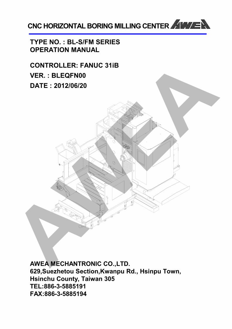
CNC HORIZONTAL BORING MILLING CENTER
TYPE NO. : BL-S/FM SERIES OPERATION MANUAL CONTROLLER: FANUC 31iB VER. : BLEQFN00 DATE : 2012/06/20
AWEA MECHANTRONIC CO.,LTD. 629,Suezhetou Section,Kwanpu Rd., Hsinpu Town, Hsinchu County, Taiwan 305 TEL:886-3-5885191 FAX:886-3-5885194
AWEA
AWEA MECHANTRONIC CO., LTD
Department of Research and Development
Materials Name: BL-S/FM+31iB Operator Instruction Manual
Materials No: BLEQFN00
Completion Date: 2012 / 06 / 20
Author: Kun-Yan Lee
R & D Dept.: Wei-Chun Yeh
AWEA Contents
I
C o n t e n t s
1. SAFETY OPERATION .................................................................................................................. 1-1 1.1 Safety Precautions ............................................................................................................. 1-1 1.2 Notes ................................................................................................................................ 1-2
1.2.1 Safety Notes ............................................................................................................... 1-2 1.2.2 Environmental Notes .................................................................................................. 1-4 1.2.3 Color Definition .......................................................................................................... 1-5 1.2.4 Beeper ....................................................................................................................... 1-6 1.2.5 Environmental Requirements ..................................................................................... 1-7 1.2.6 Installation Requirements ........................................................................................... 1-7
1.3 Remark Instruction ............................................................................................................ 1-8 1.3.1 Danger Remark ........................................................................................................... 1-8 1.3.2 Warning Remark ......................................................................................................... 1-8 1.3.3 Caution Remark .......................................................................................................... 1-8
1.4 Tag Instruction .................................................................................................................. 1-9 1.4.1 Electric Shock Tag ....................................................................................................... 1-9 1.4.2 Warning Tag of Machine Operating............................................................................. 1-9 1.4.3 Warning Tag of Workpieces Assembling/ Disassembling ........................................... 1-10 1.4.4 Warning Tag of Cutting Injuries ................................................................................. 1-10 1.4.5 Warning Tag of Twisted & Milled Injuries .................................................................. 1-11 1.4.6 Warning Tag of Tool Change Injuries ......................................................................... 1-11 1.4.7 Warning Tag of Injuries from Chip Conveyor ............................................................. 1-12 1.4.8 Warning Tag of Protective Equipment ....................................................................... 1-12
1.5 Explanation of Terminology ............................................................................................. 1-13 1.6 Safety Checks of Operation.............................................................................................. 1-16
1.6.1 Check before Starting Machine ................................................................................. 1-16 1.6.2 Check after Starting Machine ................................................................................... 1-19 1.6.3 Manual Operation Check .......................................................................................... 1-21
1.7 Instruction for CE Safety Operation (Optional) ................................................................. 1-23 1.7.1 Instruction for CE Safety Electric Lock ....................................................................... 1-23 1.7.2 Instruction for Access Door Safety Operation ............................................................ 1-24 1.7.3 Instruction for Tool Magazine Safety Operation ........................................................ 1-26 1.7.4 Safety Operation List ................................................................................................ 1-27
2. STARTING/SHUTDOWN/STOP/WARM-UP PROCEDURES ........................................................... 2-1 2.1 STARTING PROCEDURE ...................................................................................................... 2-1
2.1.1 Machine Starting Steps Instruction ............................................................................. 2-1 2.2 Shutdown Procedure ......................................................................................................... 2-4
2.2.1 Machine Shutdown Steps Instruction ......................................................................... 2-4 2.3 Stop Procedures ................................................................................................................ 2-6
2.3.1 Emergency Stop.......................................................................................................... 2-6 2.3.2 Normal Stop ............................................................................................................... 2-7 2.3.3 Power Failure Handling ............................................................................................. 2-10
2.4 WARMING UP PROCEDURE ............................................................................................. 2-11 2.4.1 Warming Up Description........................................................................................... 2-12 2.4.2 Machine Specification and Travel Instruction ............................................................ 2-12
AWEA Contents
II
3. OPERATION PANEL INSTRUCTION ............................................................................................. 3-1 3.1 Operation Panel of Machine .............................................................................................. 3-1
3.1.1 Machine Panel Instruction .......................................................................................... 3-1 3.2 Tool Magazine Operation Panel ....................................................................................... 3-25
3.2.1 Instruction of Vertical Tool Magazine Operation Panel Buttons ................................. 3-25 3.3 MPG Operation Panel ...................................................................................................... 3-29
3.3.1 MPG Panel Instruction .............................................................................................. 3-29 3.4 Chip Conveyor Operation Panel ....................................................................................... 3-32
3.4.1 Chip Conveyor Operation Panel Instruction .............................................................. 3-32 3.5 Software Operation Panel ............................................................................................... 3-35
3.5.1 Software Panel Operation Methods .......................................................................... 3-35 3.5.2 Software Operation Panel Instruction ....................................................................... 3-36
4. MANUAL OPERATION ............................................................................................................... 4-1 4.1 Manual Mode Switch Operation ........................................................................................ 4-1
4.1.1 Mode Switch Instruction............................................................................................. 4-1 4.2 Manual HOME Operation .................................................................................................. 4-3
4.2.1 Instruction for Single Axis HOME Operation................................................................ 4-3 4.2.2 Instruction for All Axes HOME Operation .................................................................... 4-4
4.3 Manual Slow Feed Operation ............................................................................................ 4-5 4.3.1 Instruction for Slow Feed Operation ........................................................................... 4-5
4.4 Manual Rapid Feed Operation ........................................................................................... 4-7 4.4.1 Instruction for Rapid Feed Operation Steps ................................................................ 4-7
4.5 Manual Spindle Running Operation ................................................................................... 4-9 4.5.1 Instruction for Manual Spindle CW Operation ............................................................ 4-9 4.5.2 Instruction for Manual Spindle CCW Operation ........................................................ 4-10 4.5.3 Instruction for Manual Spindle Stop Operation ......................................................... 4-10 4.5.4 Instruction for Manual Spindle Positioning Operation .............................................. 4-10
4.6 Manual Spindle Tool Release Operation .......................................................................... 4-12 4.6.1 Introduction of Manual Spindle Tool Release Operation ........................................... 4-12
4.7 Introduction of Manual Vertical Tool Magazine Operation ............................................... 4-14 4.7.1 Introduction of Manual Vertical Tool Magazine Operation Modes ............................ 4-14 4.7.2 Introduction of Manual Vertical Tool Magazine Operation Mode Conditions ............ 4-15 4.7.3 Introduction of Manual Vertical Tool Magazine Operation ........................................ 4-16
4.8 Manual Chip Conveyor Operation .................................................................................... 4-17 4.8.1 Instruction for Manual Chip Conveyor CW Operation ............................................... 4-17 4.8.2 Instruction for Manual Chip Conveyor CCW Operation ............................................. 4-18 4.8.3 Console Iron Removal Method ................................................................................. 4-18
4.9 Manual Coolant Operation .............................................................................................. 4-19 4.9.1 Manual Coolant Start Operation Description ............................................................ 4-19 4.9.2 Manual Coolant Stop Operation Description ............................................................. 4-19 4.9.3 Manual Coolant Gun Start Operation Description ..................................................... 4-20 4.9.4 Manual Coolant Gun Stop Operation Description ..................................................... 4-20
4.10 MPG Feed Operation ....................................................................................................... 4-21 4.10.1 Introduction for MPG Feed Operation ...................................................................... 4-21
4.11 Manual Oil Skimmer Operation (Optional) ...................................................................... 4-22 4.11.1 Manual Oil Skimmer Start Operation Description ..................................................... 4-22 4.11.2 Manual Oil Skimmer Stop Operation Description ..................................................... 4-22
AWEA Contents
III
4.12 Manual Oil Mist Cutting Operation (Optional) ................................................................. 4-23 4.12.1 Manual Oil Mist Cutting Start Operation Description ................................................ 4-23 4.12.2 Manual Oil Mist Cutting Stop Operation Description ................................................ 4-23
5. AUTO OPERATION .................................................................................................................... 5-1 5.1 Auto Program Operation Circulation.................................................................................. 5-1
5.1.1 Instruction for Auto Program Operation Circulation .................................................... 5-1 5.2 Auto Feed Operation ......................................................................................................... 5-2
5.2.1 Auto Feed Operation Description................................................................................ 5-2 5.3 Auto Spindle Running Operation ....................................................................................... 5-3
5.3.1 Instruction for Auto Spindle CW Operation ................................................................. 5-3 5.3.2 Instruction for Auto Spindle CCW Operation ............................................................... 5-3 5.3.3 Instruction for Auto Spindle Stop Operation ............................................................... 5-4 5.3.4 Instruction for Auto Spindle Positioning Operation ..................................................... 5-4
5.4 Auto Tool Magazine Operation .......................................................................................... 5-5 5.4.1 Instruction for Auto Tool Change (ATC) Operation ....................................................... 5-6 5.4.2 Instruction for Auto Pre-stage Operation of Tool ......................................................... 5-6 5.4.3 Instruction for Tool Magazine Action .......................................................................... 5-6 5.4.4 Instruction for Tool Exchange Procedure ................................................................... 5-10
5.5 Auto Chip Conveyor Operation ........................................................................................ 5-11 5.5.1 Instruction for Auto Chip Conveyor Start Operation .................................................. 5-11 5.5.2 Instruction for Auto Chip Conveyor Stop Operation .................................................. 5-12 5.5.3 Method for Iron Chip Removal on Console ............................................................... 5-12
5.6 Auto Coolant Operation .................................................................................................. 5-13 5.6.1 Instruction for Auto Coolant Start Operation ............................................................ 5-13 5.6.2 Instruction for Auto Coolant Stop Operation............................................................. 5-14
5.7 Auto Coolant Through Spindle (Optional) ........................................................................ 5-15 5.7.1 Instruction for Auto Coolant Through Spindle Start Operation .................................. 5-15 5.7.2 Instruction for Auto Coolant Through Spindle Stop Operation .................................. 5-16
5.8 Auto Coolant Through Tool Operation (Optional) ............................................................ 5-17 5.8.1 Instruction for Auto Coolant Through Tool Start Operation ....................................... 5-17 5.8.2 Instruction for Auto Coolant Through Tool Stop Operation ....................................... 5-18
5.9 Auto Oil Mist Cutting Operation (Optional) ..................................................................... 5-19 5.9.1 Introduction for Auto Oil-Mist Cutting Start Operation ............................................. 5-19 5.9.2 Instruction for Auto Oil Mist Cutting Stop Operation ................................................ 5-20
6. INSTRUCTION FOR NC OPERATION ........................................................................................... 6-1 6.1 LCD Introduced.................................................................................................................. 6-1
6.1.1 10.4" Screen (12-Key) ................................................................................................. 6-1 6.2 MDI Panel Introduction ..................................................................................................... 6-2
6.2.1 All Key Panel ............................................................................................................... 6-2 6.2.2 MDI Panel Keys Instruction ......................................................................................... 6-3
6.3 Programming Process ........................................................................................................ 6-9 6.4 Composition of Program ................................................................................................. 6-10
6.4.1 Program Structure .................................................................................................... 6-10 6.4.2 Program Structure Explanation ................................................................................. 6-11 6.4.3 Subprogram Call ....................................................................................................... 6-12 6.4.4 Address sheets ......................................................................................................... 6-13
6.5 Program Edit ................................................................................................................... 6-14
AWEA Contents
IV
6.5.1 Program Search ........................................................................................................ 6-14 6.5.2 Program Adding ........................................................................................................ 6-14 6.5.3 Program Deletion ..................................................................................................... 6-14 6.5.4 Command Address Searching ................................................................................... 6-15
6.6 Expandable Program Editing ............................................................................................ 6-16 6.6.1 Copy ......................................................................................................................... 6-16 6.6.2 Move ........................................................................................................................ 6-18 6.6.3 Insert ........................................................................................................................ 6-19 6.6.4 Alter ......................................................................................................................... 6-20
6.7 Use Memory Card to Perform DNC Processing................................................................. 6-21 6.7.1 Operation Method.................................................................................................... 6-21
6.8 Memory Card Transmission ............................................................................................. 6-23 6.8.1 Transmission Contents .............................................................................................. 6-24 6.8.2 Preparation Before Transmission .............................................................................. 6-24 6.8.3 Parameter Transmission Operation ........................................................................... 6-25 6.8.4 Program Transmission Operation .............................................................................. 6-25
6.9 Display of Processing Volume and Operation Time .......................................................... 6-26 6.9.1 Operation and Display .............................................................................................. 6-26 6.9.2 Setting Method ........................................................................................................ 6-27
6.10 Mandatory Mirror ........................................................................................................... 6-29 7. COMMAND INSTRUCTION ........................................................................................................ 7-1
7.1 Instruction of Each Description .......................................................................................... 7-1 7.1.1 G Command ............................................................................................................... 7-1 7.1.2 F Command ................................................................................................................ 7-2 7.1.3 M Command .............................................................................................................. 7-3 7.1.4 S Command ................................................................................................................ 7-4 7.1.5 T Command ................................................................................................................ 7-5
7.2 M Command List ............................................................................................................... 7-6 7.3 M Command Format Description .................................................................................... 7-10
7.3.1 M00 Program Stop ................................................................................................... 7-10 7.3.2 M01 Optional Stop ................................................................................................... 7-11 7.3.3 M02 Program End ..................................................................................................... 7-12 7.3.4 M03 / M04 / M05 Spindle CW / CCW / Stop ............................................................. 7-13 7.3.5 M06 Tool Exchange ................................................................................................... 7-14 7.3.6 M08 / M09 Coolant Start / Stop ............................................................................... 7-15 7.3.7 M13 / M14 Spindle CW / CCW and Coolant Start...................................................... 7-16 7.3.8 M19 Spindle Positioning ........................................................................................... 7-17 7.3.9 M28 Coolant Through Tool Start (Optional) .............................................................. 7-18 7.3.10 M29 Rigid Tapping .................................................................................................... 7-19 7.3.11 M30 Program End and Restore ................................................................................. 7-20 7.3.12 M51 Coolant Through Spindle (Optional).................................................................. 7-21 7.3.13 M63 / M64 Chip Screw Start / Stop .......................................................................... 7-22 7.3.14 M79 / M80 Air Blow Through Spindle Start / Stop (Optional).................................... 7-23 7.3.15 M81 / M83 Oil Mist Cutting Start / Stop (Optional) .................................................. 7-24 7.3.16 M82 / M84 Air Blow Start / Stop............................................................................... 7-25 7.3.17 M90 / M91 Workpiece Measurement Start / Stop (Optional) ................................... 7-26 7.3.18 M96 Alter MAZ / Arm / Spindle Tool NO. .................................................................. 7-27
AWEA Contents
V
7.3.19 M98 / M99 Subprogram Call ..................................................................................... 7-28 7.3.20 M100 Spindle Load Monitoring (Optional) ................................................................ 7-31 7.3.21 M101 Tool Life Management Reset ........................................................................... 7-32 7.3.22 M102 Tool Life Management’s TOOL SKIP ................................................................. 7-33 7.3.23 M105 / M106 NC4 LATCH Mode Start / Stop(Optional) ....................................... 7-34
7.3.24 M170∕M171 B-Axis Rotary Table Unclamp / Clamp ................................................ 7-35
7.3.25 M190 / M191 Aux Relay 1 Start / Stop ...................................................................... 7-36 7.3.26 M192 / M193 Aux Relay 2 Start / Stop ...................................................................... 7-37 7.3.27 M194 / M195 Aux Relay 3 Start / Stop ...................................................................... 7-38 7.3.28 M196 / M197 Aux Relay 4 Start / Stop ...................................................................... 7-39
8. FUNCTION DESCRIPTION .......................................................................................................... 8-1 8.1 Machine Status Display Function ....................................................................................... 8-1
8.1.1 Spindle Tool NO. Display ............................................................................................. 8-1 8.1.2 MAZ Tool No. Display .................................................................................................. 8-2
8.2 Screen Protection Function ............................................................................................... 8-3 8.2.1 Manual Operation Method ......................................................................................... 8-3 8.2.2 Auto Operation Method ............................................................................................. 8-3
8.3 Rigid Tapping Function ...................................................................................................... 8-4 8.3.1 Auto Rigid Tapping...................................................................................................... 8-5
8.4 Tool Life Management Function ........................................................................................ 8-6 8.4.1 Command Format ...................................................................................................... 8-6 8.4.2 Operation and Setting of Tool Life Management Function .......................................... 8-9 8.4.3 PLC Function of Tool Life Management ..................................................................... 8-11 8.4.4 Message Description of Tool Life Management ......................................................... 8-12 8.4.5 Examples Description ............................................................................................... 8-12
8.5 Color Instruction for Machine Tri-color Indicator ............................................................. 8-14 8.5.1 General Action Description ....................................................................................... 8-14 8.5.2 Mute Mode Function ................................................................................................ 8-14 8.5.3 Mute Mode Operation.............................................................................................. 8-14
8.6 Work Travel Prohibited Areas Setting Function ................................................................ 8-16 8.6.1 Work Travel Prohibited Areas Setting Description ..................................................... 8-16 8.6.2 Work Travel Prohibited Areas Setting Function Cancel Description ........................... 8-17
8.7 Energy Saving .................................................................................................................. 8-18 8.7.1 Stand-By Mode Description ...................................................................................... 8-18 8.7.2 Chip Conveyor Green Mode Description ................................................................... 8-19
8.8 Spindle Load Monitoring Function (Optional) .................................................................. 8-20 8.8.1 Spindle Load Monitoring Operation (Software) ......................................................... 8-20 8.8.2 Spindle Load Monitoring Function (Hardware) ......................................................... 8-21
8.9 Tool Return Function ....................................................................................................... 8-22 8.9.1 Operating Procedure for Tool Return Function .......................................................... 8-22
9. TROUBLESHOOTING INSTRUCTION ........................................................................................... 9-1 9.1 Guidance Function of Mechanical Fault Diagnosis ............................................................. 9-1
9.1.1 Function Description .................................................................................................. 9-1 9.1.2 Screen Switch ............................................................................................................. 9-1 9.1.3 Instruction for Guidance Windows of Fault Diagnosis ................................................. 9-2
9.2 Troubleshooting for Chip Conveyor ................................................................................... 9-4 9.3 Troubleshooting of Auto Tool Change (ATC) ....................................................................... 9-5
AWEA Contents
VI
9.4 Troubleshooting of Axial Movement Overtravel ................................................................. 9-6 9.4.1 Troubleshooting of Hardware Overtravel .................................................................... 9-6 9.4.2 Troubleshooting of Software Overtravel ..................................................................... 9-6
9.5 Servo Alarm Description .................................................................................................... 9-7 9.5.1 Servo Alarm List.......................................................................................................... 9-7
9.6 Spindle Alarm Description ............................................................................................... 9-16 9.7 General Alarm Description .............................................................................................. 9-21 9.8 General Alarm Countermeasures Description .................................................................. 9-24
9.8.1 Alarm EX1000【LOW HYD PRESS】 .......................................................................... 9-24
9.8.2 Alarm EX1001【LOW AIR PRESS】 ........................................................................... 9-25
9.8.3 Alarm EX1002【LOW CLN LEVEL】 ........................................................................... 9-25
9.8.4 Alarm EX1003【CONVEYOR MS OVERLOAD】.......................................................... 9-25
9.8.5 Alarm EX1004【LOW LUB LEVEL】 ........................................................................... 9-26
9.8.6 Alarm EX1005【SPINDLE COOLER UNIT ALARM】 ................................................... 9-26
9.8.7 Alarm EX1006【GEAR SHIFT DROP】 ....................................................................... 9-27
9.8.8 Alarm EX1007【COOLANT MS OVERLOAD】 ............................................................ 9-27
9.8.9 Alarm EX1008【HYD MS OVERLOAD】 .................................................................... 9-27
9.8.10 Alarm EX1012【MIST LUB PRESS OR LEVEL】 .......................................................... 9-28
9.8.11 Alarm EX1013【SPD FAN OVERLOAD】 .................................................................... 9-28
9.8.12 Alarm EX1014【SPD BEARING IS OVERHEATED】 ..................................................... 9-29
9.8.13 Alarm EX1015【MAZ CW/CCW MS OVERLOAD】 .................................................... 9-29
9.8.14 Alarm EX1020【LOW B AXIS LUB LEVEL】 ................................................................ 9-29
9.8.15 Alarm EX1021【B AXIS ROTARY TABLE CLAMP/UNCLAMP SWITCH ERROR】 ........... 9-30
9.8.16 Alarm EX1087【MACHINE PROBE SYSTEM: PROBE ERROR】 ................................... 9-30
9.8.17 Alarm EX1088【MACHINE PROBE SYSTEM: LOW BATTERY ALARM】 ....................... 9-30
9.8.18 Alarm EX1100【ARM UP/DOWN T-OUT】................................................................ 9-31
9.8.19 Alarm EX1101【ARM CW/CCW T-OUT】.................................................................. 9-31
9.8.20 Alarm EX1103【ARM H-MOVE T-OUT】 ................................................................... 9-32
9.8.21 Alarm EX1104【ATC TIME OUT】 ............................................................................. 9-32
9.8.22 Alarm EX1106【SPD ORIENT T-OUT】 ...................................................................... 9-33
9.8.23 Alarm EX1107【GEAR SHIFT T-OUT】 ...................................................................... 9-33
9.8.24 Alarm EX1110【SPD TOOL RLS/HLD TIME OUT】 ..................................................... 9-34
9.8.25 Alarm EX1120【COOLANT UNIT FOR HYD】 ............................................................ 9-34
9.8.26 Alarm EX1121【COOLANT UNIT FOR HYD】 ............................................................ 9-34
9.8.27 Alarm EX1200【SPD TOOL SEN ALM】 ..................................................................... 9-35
9.8.28 Alarm EX1201【ARM NOT UP ALM】....................................................................... 9-35
9.8.29 Alarm EX1202【ARM NOT MIDDLE ALM】............................................................... 9-35
9.8.30 Alarm EX1203【ARM NOT CW/CCW ALM】 ............................................................ 9-36
9.8.31 Alarm EX1205【MAZ TOOL UNCLAMP ALM】 ......................................................... 9-36
9.8.32 Alarm EX1209【ARM HAS WRONG TOOL】 ............................................................. 9-36
9.8.33 Alarm EX1210【T#INVALID】 ................................................................................... 9-37
9.8.34 Alarm EX1211【#SPD=#ARM】 ................................................................................ 9-37
9.8.35 Alarm EX1212【#ARM/SPD NE 0】 .......................................................................... 9-37
9.8.36 Alarm EX1214【ATC NOT READY】 .......................................................................... 9-38
9.8.37 Alarm EX1215【SPD EQ 0】 ..................................................................................... 9-38
AWEA Contents
VII
9.8.38 Alarm EX1216【SPD ORT DISAPPEAR】 ................................................................... 9-38
9.8.39 Alarm EX1217【SPD HEAD OT TOOL RLS AT ROTATING】 ......................................... 9-39
9.8.40 Alarm EX1218【MAZ NOT STOP】 ........................................................................... 9-39
9.8.41 Alarm EX1220【MIST ALARM】 ............................................................................... 9-39
9.8.42 Alarm EX1246【MAZ COUNTER ALARM】 ............................................................... 9-39
9.8.43 Alarm EX1300【EMERGENCY STOP】 ...................................................................... 9-40
9.8.44 Alarm EX1302【IO DEVICE NOT READY】................................................................. 9-40
9.8.45 Alarm EX1304【M## UNUSEFUL】 .......................................................................... 9-40
9.8.46 Alarm EX1305【SPINDLE ALARM】 .......................................................................... 9-41
9.8.47 Alarm EX1306【NEED IO BYPASS OP】..................................................................... 9-41
9.8.48 Alarm EX1307【UNDER FAULT STATE】 .................................................................... 9-41
9.8.49 Alarm EX1309【PARAMETER 1424 IS WRONG】 ...................................................... 9-41
9.8.50 Alarm EX1325【AT/MD OP ERR, PRESS DOOR CLOSE】 ............................................ 9-42
9.8.51 Alarm EX1326【ST/MD, ONLY MANUAL OP】 .......................................................... 9-42
9.8.52 Alarm EX1327【ST/MD OP ERR, PRESS DOOR CLOSE】 ............................................ 9-42
9.8.53 Alarm EX1328【OP ERR, SAFETY PB USE】............................................................... 9-43
9.8.54 Alarm EX1401【AUTO POWER OFF】 ...................................................................... 9-43
9.8.55 Alarm EX1700【POWER FAILURE DETECT TURN OFF】 ............................................ 9-43
9.9 General Message Description .......................................................................................... 9-44 9.10 General Message Countermeasure Description ............................................................... 9-46
9.10.1 Message OP2000【LOW TANK OVERFLOW】 ........................................................... 9-46
9.10.2 Message OP2001【LOW LUB PRESS】 ..................................................................... 9-46
9.10.3 Message OP2002【LOW LUB LEVEL】 ...................................................................... 9-47
9.10.4 Message OP2003【OPERATION OF FRONT DOOR IS INVALID】 ................................ 9-47
9.10.5 Message OP2004【IO SENSOR BYPASS】 ................................................................. 9-47
9.10.6 Message OP2005【HYD SEN BYPASS】 .................................................................... 9-47
9.10.7 Message OP2006【AIR SEN BYPASS】 ...................................................................... 9-48
9.10.8 Message OP2007【CLN LEVEL BYPASS】 .................................................................. 9-48
9.10.9 Message OP2008【MAZ ATC DOOR BYPASS】 .......................................................... 9-48
9.10.10 Message OP2009【GEAR LUB SEN BYPAS】 ............................................................. 9-48
9.10.11 Message OP2010【LUB. LEVEL BYPASS】 ................................................................. 9-49
9.10.12 Message OP2011【SAFE DOOR BYPASS】 ................................................................ 9-49
9.10.13 Message OP2013【TOOL GROUP LIFE END】 ........................................................... 9-49
9.10.14 Message OP2014【OPERATION OF MAZ MAN DOOR IS INVALID】 .......................... 9-50
9.10.15 Message OP2015【LOW CLN LEVEL】 ...................................................................... 9-50
9.10.16 Message OP2020【HANDLE INTERRUPT MODE ERROR】 ........................................ 9-50
9.10.17 Message OP2021【CHIP OP ERROR, CHECK BED CHIP OP】 ..................................... 9-50
9.10.18 Message OP2022【ATC TOOL CHECK ERROR】 ........................................................ 9-51
9.10.19 Message OP2023【HEAD CLAMP LS BYPASS】 ......................................................... 9-51
9.10.20 Message OP2024【OP ERROR, CHECK BED OP PANEL ENABLE KEY】 ....................... 9-51
9.10.21 Message OP2026【SPINDLE OVERLOAD】 ............................................................... 9-51
9.10.22 Message OP2028【SPINDLE OVER SPEED】 ............................................................. 9-52
9.10.23 Message OP2030【MAZ DOOR OPEN】 ................................................................... 9-52
9.10.24 Message OP2031【MAZ DOOR CLOSE STATE】 ........................................................ 9-52
9.10.25 Message OP2032【MAZ OPERATION】 .................................................................... 9-52
AWEA Contents
VIII
9.10.26 Message OP2035【LOW MIST CUT OIL LEVE】 ........................................................ 9-53
9.10.27 Message OP2036【CTS FILTER PRESSURE IS INVALID】 ............................................ 9-53
9.10.28 Message OP2037【FILTER PRESSURE IS INVALID】 .................................................. 9-53
9.10.29 Message OP2038【LOW AIR PRESSURE】 ................................................................ 9-54
9.10.30 Message OP2060【MAZ ARM ROTATION OP ERROR】 ............................................. 9-54
9.10.31 Message OP2061【MAZ ROTATION OP ERROR】 ..................................................... 9-54
9.10.32 Message OP2062【MAZ ARM UP/DWN OP ERROR】 ............................................... 9-55
9.10.33 Message OP2063【MAZ ARM H-MOVE OP ERROR】 ............................................... 9-55
9.10.34 Message OP2069【CALL TOOL ERROR】 .................................................................. 9-56
9.10.35 Message OP2070【ATC MAINTENANCT MODE USE】 .............................................. 9-56
9.10.36 Message OP2080【LOW B AXIS LUB LEVEL】 ........................................................... 9-56
9.11 Macro Alarm Description ................................................................................................ 9-57 9.12 Macro Alarm Countermeasure Description...................................................................... 9-59
9.12.1 Alarm MC3002【WITHOUT H CODE】 ..................................................................... 9-59
9.12.2 Alarm MC3004【INVALID H CODE】 ........................................................................ 9-59
9.12.3 Alarm MC3005【ATLM PROBE ERROR】 .................................................................. 9-59
9.12.4 Alarm MC3008【TOOL OFFSET TYPE SET ERROR】 .................................................. 9-60
9.12.5 Alarm MC3009【TOOL WEAR EXCEED SET RANGE】 ................................................ 9-60
9.12.6 Alarm MC3010【MACHINE LOCK/Z CANCEL】 ......................................................... 9-60
9.12.7 Alarm MC3021【K IS EMPTY】 ................................................................................ 9-60
9.12.8 Alarm MC3022【K IS INVALID】............................................................................... 9-61
9.12.9 Alarm MC3025【WITHOUT W CODE】 .................................................................... 9-61
9.12.10 Alarm MC3030【T CODE ERROR】........................................................................... 9-61
9.12.11 Alarm MC3031【K CODE ERROR】 .......................................................................... 9-61
9.12.12 Alarm MC3034【WITHOUT R CODE】 ..................................................................... 9-62
9.12.13 Alarm MC3035【WITHOUT F CODE】 ...................................................................... 9-62
9.12.14 Alarm MC3036【WITHOUT B CODE】 ..................................................................... 9-62
9.12.15 Alarm MC3039【C AXIS SET IS INVALID】 ................................................................ 9-62
9.12.16 Alarm MC3040【C IS EMPTY】 ................................................................................ 9-63
9.12.17 Alarm MC3042【M59V1. COMMAND MISSING】 .................................................... 9-63
9.12.18 Alarm MC3043【M59V2. COMMAND MISSING】 .................................................... 9-63
9.12.19 Alarm MC3044【M59V3. COMMAND MISSING】 .................................................... 9-63
9.12.20 Alarm MC3045【V&H CODE BOTH SET】 ................................................................. 9-63
9.12.21 Alarm MC3046【V CODE VALUE OVER RANGE】 ..................................................... 9-64
9.12.22 Alarm MC3047【V&H CODE BOTH EMPTY】 ........................................................... 9-64
9.12.23 Alarm MC3048【H CODE VALUE OVER RANGE】 ..................................................... 9-64
9.12.24 Alarm MC3050【LOST #A】 ..................................................................................... 9-64
9.12.25 Alarm MC3051【INVALID A CODE】 ........................................................................ 9-64
9.12.26 Alarm MC3060【INPUT DATA RANGE EXCEED】 ...................................................... 9-65
9.12.27 Alarm MC3090【HEAD NOT AT SPINDLE】............................................................... 9-65
9.12.28 Alarm MC3091【90HEAD NOT AT SPINDLE】 ........................................................... 9-65
9.12.29 Alarm MC3095【UNVHD NOT AT SPINDLE】 ........................................................... 9-65
9.12.30 Alarm MC3100【SPINDLE IS EMPTY】 ..................................................................... 9-66
9.12.31 Alarm MC3101【SPINDLE IS EXTHD】 ...................................................................... 9-66
9.12.32 Alarm MC3110【SPINDLE IS HEAD】 ....................................................................... 9-66

AWEA Contents
IX
9.12.33 Alarm: MC3120【STOCK NO. SET ERROR】 .............................................................. 9-66
9.12.34 Alarm: MC3160【HEAD NOT CLAMP】 .................................................................... 9-67
AWEA Figure Content
X
F i g u r e C o n t e n t
Fig 1.3-1 Danger Remark ................................................................................................................... 1-8 Fig 1.3-2 Warning Remark ................................................................................................................. 1-8 Fig 1.3-3 Caution Remark .................................................................................................................. 1-8 Fig 1.4-1 Electric Shock Tag ............................................................................................................... 1-9 Fig 1.4-2 Warning Tag of Machine Operating ..................................................................................... 1-9 Fig 1.4-3 Warning Tag of Setup ........................................................................................................ 1-10 Fig 1.4-4 Warning Tag of Cutting Injuries ......................................................................................... 1-10 Fig 1.4-5 Warning Tag of Twisted & Milled Injuries .......................................................................... 1-11 Fig 1.4-6 Warning Tag of Tool Change Injuries ................................................................................. 1-11 Fig 1.4-7 Warning Tag of Injuries from Chip Conveyor ..................................................................... 1-12 Fig 1.4-8 Warning Tag of Protective Equipment ............................................................................... 1-12 Fig 1.7-1 Kinds of Safety Electric Lock Switch ................................................................................... 1-23 Fig 1.7-2 Installation Position of Safety Electric Lock Switch............................................................. 1-23 Fig 2.3-1 Diagram of Emergency Switch Position ............................................................................... 2-6 Fig 2.3-2 signal block Operation Button & Motion ............................................................................. 2-8 Fig 2.3-3 Cycle Stop Button ............................................................................................................... 2-8 Fig 2.3-4 Feed Hold Button ................................................................................................................ 2-9 Fig 2.3-5 Spindle Stop Button ............................................................................................................ 2-9 Fig 2.3-6 Reset Stop Button ............................................................................................................... 2-9 Fig 2.4-1 Diagram of Machine Warming Up ..................................................................................... 2-11 Fig 3.1-1 Operation Panel of Machine ............................................................................................... 3-1 Fig 3.1-2 Emergency Stop Button ...................................................................................................... 3-2 Fig 3.1-3 Mode Selection Button ....................................................................................................... 3-2 Fig 3.1-4 Feed Rate Adjust Button ..................................................................................................... 3-3 Fig 3.1-5 Spindle RPM Adjust Button ................................................................................................. 3-3 Fig 3.1-6 Rapid Feed Knob ................................................................................................................. 3-4 Fig 3.1-7 Slow Feed Knob .................................................................................................................. 3-4 Fig 3.1-8 Servo Activation Button ...................................................................................................... 3-5 Fig 3.1-9 Spindle CW Button .............................................................................................................. 3-5 Fig 3.1-10 Spindle CCW Button .......................................................................................................... 3-5 Fig 3.1-11 Spindle Stop Button .......................................................................................................... 3-6 Fig 3.1-12 Spindle Positioning Button ................................................................................................ 3-6 Fig 3.1-13 Cycle Start Button ............................................................................................................. 3-7 Fig 3.1-14 Cycle Stop Button ............................................................................................................. 3-7 Fig 3.1-15 Feed Hold Button .............................................................................................................. 3-7 Fig 3.1-16 Signal Block Button ........................................................................................................... 3-8 Fig 3.1-17 Block Skip Button .............................................................................................................. 3-8 Fig 3.1-18 DRY RUN Button ............................................................................................................... 3-8 Fig 3.1-19 OPT. STP Button ................................................................................................................ 3-9 Fig 3.1-20 Auto Power OFF Button .................................................................................................... 3-9 Fig 3.1-21 Handle Interrupt Button ................................................................................................... 3-9 Fig 3.1-22 Tool No. Display Button ................................................................................................... 3-10 Fig 3.1-23 All Axes HOME Button ..................................................................................................... 3-10 Fig 3.1-24 O.T.REL Button (Overtravel Release) ................................................................................ 3-11
AWEA Figure Content
XI
Fig 3.1-25 X-Axis (+) Direction Button .............................................................................................. 3-11 Fig 3.1-26 X-Axis (-) Direction Button ............................................................................................... 3-11 Fig 3.1-27 Y-Axis (+) Direction Button .............................................................................................. 3-12 Fig 3.1-28 Y-Axis (-) Direction Button ............................................................................................... 3-12 Fig 3.1-29 Z-Axis (+) Direction Button .............................................................................................. 3-12 Fig 3.1-30 Z-Axis (-) Direction Button ............................................................................................... 3-13 Fig 3.1-31 W-Axis (+) Direction Button ............................................................................................. 3-13 Fig 3.1-32 W-Axis (-) Direction Button ............................................................................................. 3-13 Fig 3.1-33 B-Axis (+) Direction Button .............................................................................................. 3-14 Fig 3.1-34 B-Axis (-) Direction Button .............................................................................................. 3-14 Fig 3.1-35 B-Axis Unclamp Button ................................................................................................... 3-14 Fig 3.1-36 Coolant Control Button ................................................................................................... 3-15 Fig 3.1-37 Coolant Gun Control Button ............................................................................................ 3-15 Fig 3.1-38 Chip Conveyor Control Button ......................................................................................... 3-15 Fig 3.1-39 Work Light Control Button .............................................................................................. 3-16 Fig 3.1-40 Operator Room Work Light Control Button ..................................................................... 3-16 Fig 3.1-41 Manual Air Blow Button .................................................................................................. 3-16 Fig 3.1-42 Buzzer OFF Button .......................................................................................................... 3-17 Fig 3.1-43 Message Reset Button .................................................................................................... 3-17 Fig 3.1-44 Program Protection Key Switch ....................................................................................... 3-17 Fig 3.1-45 Manual Spindle Tool Release Button ............................................................................... 3-18 Fig 3.1-46 Auto and Setting Mode Key Switch ................................................................................. 3-18 Fig 3.1-47 Operation Enable Key Switch .......................................................................................... 3-19 Fig 3.1-48 Tool Return Button .......................................................................................................... 3-19 Fig 3.1-49 Oil-mist Cutting Control Button ...................................................................................... 3-19 Fig 3.1-50 Access Door Open Button ............................................................................................... 3-20 Fig 3.1-51 Safety Operation Button ................................................................................................. 3-20 Fig 3.1-52 Spindle High Gear Status Indicator .................................................................................. 3-20 Fig 3.1-53 Spindle Low Gear State Indicator .................................................................................... 3-21 Fig 3.1-54 X-axis Mechanical Home Position Indicator ..................................................................... 3-21 Fig 3.1-55 Y-axis Mechanical Home Position Indicator ..................................................................... 3-21 Fig 3.1-56 Z-axis Mechanical Home Position Indicator ..................................................................... 3-21 Fig 3.1-57 W-axis Mechanical Home Position Indicator .................................................................... 3-22 Fig 3.1-58 B-axis Mechanical Home Position Indicator ..................................................................... 3-22 Fig 3.1-59 ATC System Ready Indicator ............................................................................................ 3-22 Fig 3.1-60 Mandatory Indicator ....................................................................................................... 3-23 Fig 3.1-61 Message Indicator ........................................................................................................... 3-23 Fig 3.1-62 Alarm Indicator ............................................................................................................... 3-23 Fig 3.1-63 Emergency Stop Indicator ............................................................................................... 3-24 Fig 3.1-64 Spindle load meter .......................................................................................................... 3-24 Fig 3.2-1 Tool Magazine Operation Panel ......................................................................................... 3-25 Fig 3.2-2 Emergency Stop Button .................................................................................................... 3-25 Fig 3.2-3 Tool Magazine Manual Mode Selection Button ................................................................. 3-26 Fig 3.2-4 Fault Reset Button ............................................................................................................ 3-26 Fig 3.2-5 Manual Start Button ......................................................................................................... 3-27 Fig 3.2-6 MAZ Operation Enable Key Switch .................................................................................... 3-27 Fig 3.2-7 Tool Magazine Panel Status Indicator ................................................................................ 3-28
AWEA Figure Content
XII
Fig 3.2-8 MAZ Door Open Button .................................................................................................... 3-28 Fig 3.3-1 MPG Operation Panel ....................................................................................................... 3-29 Fig 3.3-2 Axis selection button of MPG ............................................................................................ 3-29 Fig 3.3-3 MPG Override Button ....................................................................................................... 3-29 Fig 3.3-4 Manual Pulse Generator (MPG) ........................................................................................ 3-30 Fig 3.3-5 Emergency Stop Button .................................................................................................... 3-30 Fig 3.3-6 MPG Active Indicator ........................................................................................................ 3-30 Fig 3.3-7 MPG Enable Button .......................................................................................................... 3-31 Fig 3.4-1 Chip Conveyor Operation Panel ........................................................................................ 3-32 Fig 3.4-2 Emergency Stop Button .................................................................................................... 3-32 Fig 3.4-3 Chip Conveyor CW Button ................................................................................................. 3-33 Fig 3.4-4 Chip Conveyor CCW Button ............................................................................................... 3-33 Fig 3.4-5 Chip Conveyor Stop Button ............................................................................................... 3-33 Fig 3.4-6 Chip Conveyor Operation Panel Enable Key Switch............................................................ 3-34 Fig 3.4-7 Chip Conveyor Motion Indicator ....................................................................................... 3-34 Fig 3.5-1 Software Operation Panel Screen ...................................................................................... 3-35 Fig 4.7-1 Manual Tool Magazine Modes .......................................................................................... 4-14 Fig 4.8-1 Chip Conveyor System Diagram......................................................................................... 4-17 Fig 4.9-1 Coolant Structure Diagram................................................................................................ 4-19 Fig 4.11-1 OIL SKIMMER .................................................................................................................. 4-22 Fig 4.12-1 Oil Mist Cutting Mechanism Diagram.............................................................................. 4-23 Fig 5.4-1 MAZ Mechanism Diagram ................................................................................................... 5-5 Fig 5.4-2 Pre-stage Tool Description .................................................................................................. 5-7 Fig 5.4-3 Tool Change Action Description........................................................................................... 5-9 Fig 5.5-1 Chip Conveyor System Diagram......................................................................................... 5-11 Fig 5.6-1 Coolant Structure Diagram................................................................................................ 5-13 Fig 5.7-1 Coolant Through Spindle Structure Diagram ..................................................................... 5-15 Fig 5.8-1 Coolant Through Tool Scheme .......................................................................................... 5-17 Fig 5.9-1 Oil Mist Cutting Mechanism Diagram ............................................................................... 5-19 Fig 6.1-1 Screen Diagram................................................................................................................... 6-1 Fig 6.2-1 MDI Panel Diagram ............................................................................................................. 6-2 Fig 6.2-2【POS】Keys Diagram ......................................................................................................... 6-3
Fig 6.2-3【PRGRM】Keys Diagram ................................................................................................... 6-4
Fig 6.2-4【OFFSET SETTING】Keys Diagram...................................................................................... 6-4
Fig 6.2-5【SYSTEM】Keys Diagram ................................................................................................... 6-4
Fig 6.2-6【GRAPH】Keys Diagram .................................................................................................... 6-5
Fig 6.2-7【MESSAGE】Keys Diagram ................................................................................................ 6-5
Fig 6.2-8【RESET】Keys Diagram ...................................................................................................... 6-5
Fig 6.2-9【CAN】Key Diagram .......................................................................................................... 6-5
Fig 6.2-10【INPUT】Key Diagram ..................................................................................................... 6-6
Fig 6.2-11【MOVE CURSOR】Key Diagram ....................................................................................... 6-6
Fig 6.2-12【PAGE UP】Key Diagram ................................................................................................. 6-6
Fig 6.2-13【PAGE DOWN】Key Diagram ........................................................................................... 6-7
Fig 6.2-14【ALTER】Key Diagram ..................................................................................................... 6-7
Fig 6.2-15【INSERT】Key Diagram .................................................................................................... 6-7
Fig 6.2-16【DELETE】Key Diagram ................................................................................................... 6-7
AWEA Figure Content
XIII
Fig 6.2-17【ADDRESS】and【VALUE】Buttons ................................................................................ 6-8
Fig 6.2-18 Left Softkey Diagram ......................................................................................................... 6-8 Fig 6.2-19 Right Softkey Diagram ....................................................................................................... 6-8 Fig 6.3-1 Program Production Flow Chart .......................................................................................... 6-9 Fig 6.4-1 Main Program Structure ................................................................................................... 6-10 Fig 6.4-2 Sub-Program Structure ..................................................................................................... 6-10 Fig 6.4-3 Subprogram Call Example ................................................................................................. 6-12 Fig 6.6-1 Illustration of Copy all program ......................................................................................... 6-16 Fig 6.6-2 Illustration of Copy part of the program ............................................................................ 6-17 Fig 6.6-3 Illustration of Moving program ......................................................................................... 6-18 Fig 6.6-4 Illustration of Insert program ............................................................................................ 6-19 Fig 6.8-1 Remove Memory Card in Safe Mode ................................................................................. 6-23 Fig 6.8-2 Remove Memory Card in Safe Mode from PC ................................................................... 6-23 Fig 6.8-3 Parameters Writeable Setting ........................................................................................... 6-24 Fig 6.8-4 ALL I/O Screen .................................................................................................................. 6-25 Fig 6.9-1 Display of Processing Volume and Operation Time ........................................................... 6-26 Fig 6.9-2 SETTING (Timer) Screen .................................................................................................... 6-27 Fig 6.10-1 Mirror Function Description ............................................................................................ 6-29 Fig 6.10-2 Screen of Mirror Setting .................................................................................................. 6-29 Fig 7.3-1 M02 Command illustration ............................................................................................... 7-12 Fig 8.1-1 Spindle Tool NO. Display Screen .......................................................................................... 8-1 Fig 8.1-2 MAZ Tool NO. Display screen .............................................................................................. 8-2 Fig 8.2-1 Screen Protection Functional Description ........................................................................... 8-3 Fig 8.3-1 Description of Elastic Chuck and Collect Chuck.................................................................... 8-4 Fig 8.6-1 Work Travel Prohibited Areas Schematic Diagram ............................................................. 8-16 Fig 8.6-2 Work Travel Prohibited Areas Setting Legend .................................................................... 8-17 Fig 8.8-1 Meter of Spindle Load Monitoring Hardware .................................................................... 8-21 Fig 8.9-1 Illustration of Tool Return. ................................................................................................ 8-22 Fig 9.1-1 Message Function Key ........................................................................................................ 9-1 Fig 9.1-2 Guidance Screen of Fault Diagnosis..................................................................................... 9-1 Fig 9.1-3 Layout of Guidance Windows of Fault Diagnosis ................................................................. 9-2 Fig 9.1-4 Operation of Guidance Message ......................................................................................... 9-2 Fig 9.2-1 Chip Conveyor Structure ..................................................................................................... 9-4
AWEA Table Content
XIV
T a b l e C o n t e n t
Table 1.2-1 Color Description List for Panel Indicator ......................................................................... 1-5 Table 1.2-2 Color List for Machine Tri-color Indicator ......................................................................... 1-6 Table 1.2-3 Acoustics Description List for Machine Beeper ................................................................ 1-6 Table 1.7-1 List for Manual Safety Operation ................................................................................... 1-28 Table 1.7-2 List of Safety Operation of Command ............................................................................ 1-28 Table 2.3-1 Power Failure Mechanism Status Table ......................................................................... 2-10 Table 2.4-1 List of Machine Specification and Travel ........................................................................ 2-12 Table 5.4-1 Tool Exchange Procedure List ........................................................................................ 5-10 Table 6.4-1 Address Description List ................................................................................................ 6-13 Table 7.2-1 M Command List ............................................................................................................. 7-9 Table 7.3-1 Rigid Tapping Command Format List ............................................................................. 7-19 Table 7.3-2 Alter Tool No. Command Format List ............................................................................. 7-27 Table 7.3-3 Subprogram Call Command Format List......................................................................... 7-28 Table 7.3-4 Spindle Load Monitoring Command Format List ............................................................ 7-31 Table 7.3-5 Tool Life Management Reset Command Format List ...................................................... 7-32 Table 8.3-1 Comparison Table of General and Rigid Tapping .............................................................. 8-4 Table 9.5-1 Servo Alarm List ............................................................................................................ 9-15 Table 9.6-1 Spindle Alarm List.......................................................................................................... 9-20 Table 9.7-1 General Alarm List ......................................................................................................... 9-23 Table 9.9-1 General Message List .................................................................................................... 9-45 Table 9.11-1 Macro Alarm List ......................................................................................................... 9-58
AWEA 1、Safety Operation
1-1
1. Safety Operation
In order to promote the production efficiency of CNC machine tools, it often uses automatic
machining with high power and high speed. It will cause you injured or the machine damages
enormously if any careless. Therefore, the operators must not only be familiar with the structure,
the function and the operation method of CNC machine tools, but also be careful of their own and
other nearby colleagues’ safety.
Although CNC machine tools have various safety systems, it is often unable to predict the disaster
incurred by human negligence. Therefore, in addition to general factory safety requirements, the
operators shall obey following work safety precautions to make sure their own safety.
1.1 Safety Precautions
CAUTION
1. Be familiar with the correct operation method and safety procedure of this machine first.
Before starting the machine, for use. Otherwise, it is not allowed to use this machine.
2. Untrained staffs are prohibited from operating and maintain this machine.
3. DO NOT operate the machine as feeling unwell physically or mentally.
4. There must be sufficient lights around the workplace.
5. Pay attention to the caution items in the tag frequently. NEVER tear off or spoil the tags.
6. 2 workers and above are required to transport large workpieces.
7. The operators must know the location of emergency switch and how to use it.
8. DO NOT go near the machine as operating. NEVER put your head and hands into the
travel.
9. Dress proper work wears (including: safety shoes, helmet, safety glasses) as setup the
workpiece or servicing.
10. Make sure to install the tool well, clamp the workpiece tightly and check there is not
impeding the machine movement.
11. Shutdown the machine before servicing.
12. As the machine is processing without monitor, it would be best to use coolant to reduce
sparks in order to avoid from any disaster.
An accident is easy to take place and further causes serious damages without obeying such
precautions.Any unclear or doubts about the safety precautions or operation procedures,
please contact the dealer immediately.
AWEA 1、Safety Operation
1-2
1.2 Notes
CAUTION
"Read the precautions for operating safety and environmental protection carefully before
operating the machine."
The purpose of our company in planning and designing the machine is to make our users get the
easiest and the safest operating principles.
It is worthy of re-explaining the importance of safety requirements and procedures in order to
make our user pay attentions and get a safe and healthy protection and to fulfill our
environmental recycle duties.
It is recommended that the factory management shall require their maintenance department
staffs and machine & tool users to read following safety and environmental protection items
carefully before using and servicing the machine.
1.2.1 Safety Notes
1. DO NOT operate and maintain the machine. Only for qualified trained and authorized
personnel.
2. Read the Instruction manual carefully before operating or servicing the machine and
make sure to fully understand all instruction.
3. If not fully understand the correct operating method, consult with the management for
solution.
4. Before fully aware of this machine, DO NOT use this machine without authorization to
avoid from any accidents.。
5. If the situation of this machine cannot be not solved in accordance with the instruction
manual, contact the dealers.
6. NEVER using this machine in any environment possibly causing gas explosion.
7. The electrical of this machine is designed in accordance with the criteria of
“EN60204-1”.
8. Make sure the machine is located in a place with stable base.
9. Make sure various machine adjustments and calibrations are completed.
10. Make sure proper machine grounding has been processed.
11. Keep the lights sufficient and the ground dry around the machine.
12. Be well aware of the location of all “Emergency Stop” buttons.
13. DO NOT remove any safety warning or operating command tags from the machine.
AWEA 1、Safety Operation
1-3
14. DO NOT reduce or stop the machine speed by hands, tools or additional equipments.
15. DO NOT connect any interlock, overload or safety devices beside the power supply of
machine.
16. Before starting the machine, make sure the mechanical pieces are complete and all
failure factors are resolved first.
17. Before starting the machine, replace defected the clamps and tighten the unclamping
parts first.
18. Before starting the machine, clean up unneeded goods on the machine, especially after
maintenance.
19. Before starting the machine, check the coolant volume.
20. After starting the machine, check if the hydraulic fluid volume & the pressure are
sufficient and the indicator is normal.
21. After starting the machine, please check if the hydraulic volume and pressure sufficient,
and the indicator normal.
22. As operating, make the machine Home Return first to avoid from overtravel.
23. As operating, make sure various functions are normal to ensure the processing quality.
24. As operating, record the operating procedure to resolve the abnormity if there is any
abnormal.
25. Before processing, check if the tools are correct, clamped exactly and their positions
are correct.
26. Before processing, please check if the workpieces baseline and position correct and are
fixed exactly.
27. Before processing, make sure the program is edited completely and the parameters as
well as the switch are set well.
28. Before processing, run the inspection program first to check if it is correct, especially
for new programs.
29. As operating, NEVER setup the workpieces to avoid from any casualties.
30. As operating, NEVER setup workpieces on the machine. Failure to follow will result in
casualties.
31. As operating, NEVER clean the chips on the workpieces. Failure to follow will result in
casualties.
32. As operating, use screen and panel to display the failure for diagnosis if there is any
failure.
33. Improper use or excess over the machine capacity will damage the machine and
endanger staffs.
34. Check if the tool and the workpiece are fixed completely as restarting the machine
after long-period unused.
AWEA 1、Safety Operation
1-4
35. Wear gloves if it is possible to injure your hands as setup the workpiece, cleaning up
the lathe, changing the fluid or servicing the machine.
36. As setup the workpiece, DO NOT wear gloves to avoid from any error operation and
being drawn into the machine.
37. As operating the machine on the operation panel and cleaning the Chip screw and the
chip conveyor, DO NOT wear gloves to avoid from any error operation and being drawn
into the machine.
38. DO NOT setup spare parts and electrical equipments by an unauthorized or
unapproved maintenance staff.
39. Before checking or servicing the machine, switch off the power supply to avoid from
electric shock.
40. DO NOT open and touch the interior of operator cabinet or electric cabinet before
switching off the power supply (power indicator is still lit on).
41. DO NOT touch the electrical equipment with wet hands or standing at the coolant.
42. Pay attention to the warning tag near machine or tools to avoid from any accident.
43. Use the tools with proper size and type. NEVER use damaged or defected tools.
44. Tap by rubber hammer with soft surface and clean up tools first before setup spare
parts.
45. Replace the fuse in accordance with the Original required specification after excluding
the fuse-burn reason.
46. The operators shall call for help as trapped in the machine and use the ladder to leave
the console.
1.2.2 Environmental Notes
1. Clean up chips at any time to avoid from fire.
2. NEVER processing low-ignited metal materials (such as magnesium, woods, graphite,
plastic and so on).
3. This machine can process such materials as cast iron, steel, copper as well as aluminum
and also can make such processing as milling, drilling as well as tapping.
4. DO NOT use toxic or flammable fluids as rinse solvents or coolants.
5. DO NOT place chemicals or combustibles near the electric cabinet or operator panel.
6. As setup, wear safety shoes and gloves to avoid from injury.
7. As setup, pay attention to the sharp edges of workpieces and tools to avoid from cuts.
8. As setup, NEVER clean up the machines by hands or compressed air but use cleaning
tools.
9. Before processing, check if all stamping guards are closed and fixed well.

AWEA 1、Safety Operation
1-5
10. As operating, NEVER opening the protective door to avoid from chip pollution and
human injury.
11. As the machine operates abnormally, stop using the machine and record prevailing
conditions such as noise, vibration, sound, smoke, heat source and damaged place of
spare parts.
12. As processing, wear masks, helmets and safety glasses for precautions.
13. Make sure to perform waste disposal (such as: rag, oil, coolant) well for
environmentally friendly.
14. Recycle all recyclable materials (chips, changed parts for maintenance) well in order to
reduce the waste of recourses.
15. Use sawdust and rag to recycle the accidentally spilled oil.
16. It is recommended to handle scrapped machines as second-hand machines or to
disassemble those machines for recycle to meet the requirements of local
environmental regulations.
1.2.3 Color Definition
Instruction for Panel Indicator Color
Color Meaning Description Example
Red Emergency Activated upon danger and
emergency
Trigger Emergency Stop or
Emergency Function
Yellow Abnormal Activated upon abnormal
condition
Display abnormal states of
each parts of machine
Green Normal
Activated upon safety
condition or normal
preparation
Programmer under
activation
Blue Mandatory Activated upon enforcement
required Reset function
White Not Specific
Table 1.2-1 Color Description List for Panel Indicator
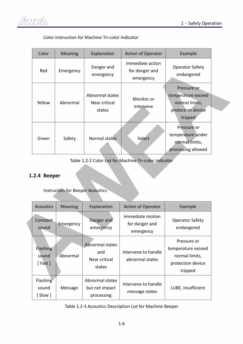
AWEA 1、Safety Operation
1-6
Color Instruction for Machine Tri-color Indicator
Color Meaning Explanation Action of Operator Example
Red Emergency Danger and
emergency
Immediate action
for danger and
emergency
Operator Safety
endangered
Yellow Abnormal
Abnormal states
Near critical
states
Monitor or
intervene
Pressure or
temperature exceed
normal limits,
protection device
tripped
Green Safety Normal states Select
Pressure or
temperature under
normal limits,
processing allowed
Table 1.2-2 Color List for Machine Tri-color Indicator
1.2.4 Beeper
Instruction for Beeper Acoustics
Acoustics Meaning Explanation Action of Operator Example
Constant
sound Emergency
Danger and
emergency
Immediate motion
for danger and
emergency
Operator Safety
endangered
Flashing
sound
[ Fast ]
Abnormal
Abnormal states
and
Near critical
states
Intervene to handle
abnormal states
Pressure or
temperature exceed
normal limits,
protection device
tripped
Flashing
sound
[ Slow ]
Message
Abnormal states
but not impact
processing
Intervene to handle
message states LUBE, insufficient
Table 1.2-3 Acoustics Description List for Machine Beeper
AWEA 1、Safety Operation
1-7
1.2.5 Environmental Requirements
The environmental requirements in the vicinity for packing and storage of machine are as
below:
1. Temperature: - 25 ℃ ~ 55 ℃
2. Humidity: 30 % ~ 95 % RH.
3. Environment: NEVER be placed on the environment with excessive dust, acid gases,
corrosive gases or salts.
1.2.6 Installation Requirements
1. Voltage: 3-phase 220 Vac, ± 5 %
2. Frequency: 50/60 Hz, ± 1 Hz
3. Ambient Temperature: 5 ℃ ~ 40 ℃
4. Ambient Humidity: 30 % ~ 75 % RH
5. Electrical equipment can be operated properly under sea level, 1000m below.
6. Environment: NEVER be placed on the environment with excessive dust, acid gases,
corrosive gases or salts.
7. Avoid to be irradiated directly by the sun or radiation.
8. Vibration: < 0.5 G.
9. Machine should be earthed.
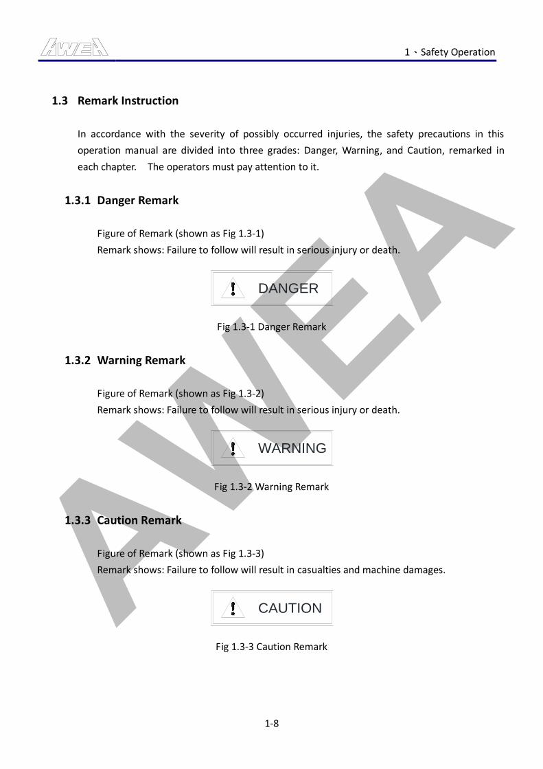
AWEA 1、Safety Operation
1-8
1.3 Remark Instruction
In accordance with the severity of possibly occurred injuries, the safety precautions in this
operation manual are divided into three grades: Danger, Warning, and Caution, remarked in
each chapter. The operators must pay attention to it.
1.3.1 Danger Remark
Figure of Remark (shown as Fig 1.3-1)
Remark shows: Failure to follow will result in serious injury or death.
DANGER
Fig 1.3-1 Danger Remark
1.3.2 Warning Remark
Figure of Remark (shown as Fig 1.3-2)
Remark shows: Failure to follow will result in serious injury or death.
WARNING
Fig 1.3-2 Warning Remark
1.3.3 Caution Remark
Figure of Remark (shown as Fig 1.3-3)
Remark shows: Failure to follow will result in casualties and machine damages.
CAUTION
Fig 1.3-3 Caution Remark
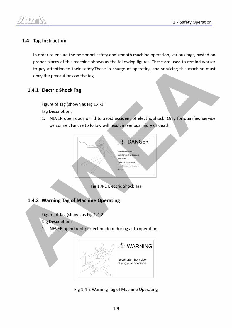
AWEA 1、Safety Operation
1-9
1.4 Tag Instruction
In order to ensure the personnel safety and smooth machine operation, various tags, pasted on
proper places of this machine shown as the following figures. These are used to remind worker
to pay attention to their safety.Those in charge of operating and servicing this machine must
obey the precautions on the tag.
1.4.1 Electric Shock Tag
Figure of Tag (shown as Fig 1.4-1)
Tag Description:
1. NEVER open door or lid to avoid accident of electric shock. Only for qualified service
personnel. Failure to follow will result in serious injury or death.
DANGER
Never open door.
Only for qualified service
personnel.
Failure to follow will
result in serious injury or
death.
Fig 1.4-1 Electric Shock Tag
1.4.2 Warning Tag of Machine Operating
Figure of Tag (shown as Fig 1.4-2)
Tag Description:
1. NEVER open front protection door during auto operation.
Never open front door
during auto operation.
WARNING
Fig 1.4-2 Warning Tag of Machine Operating
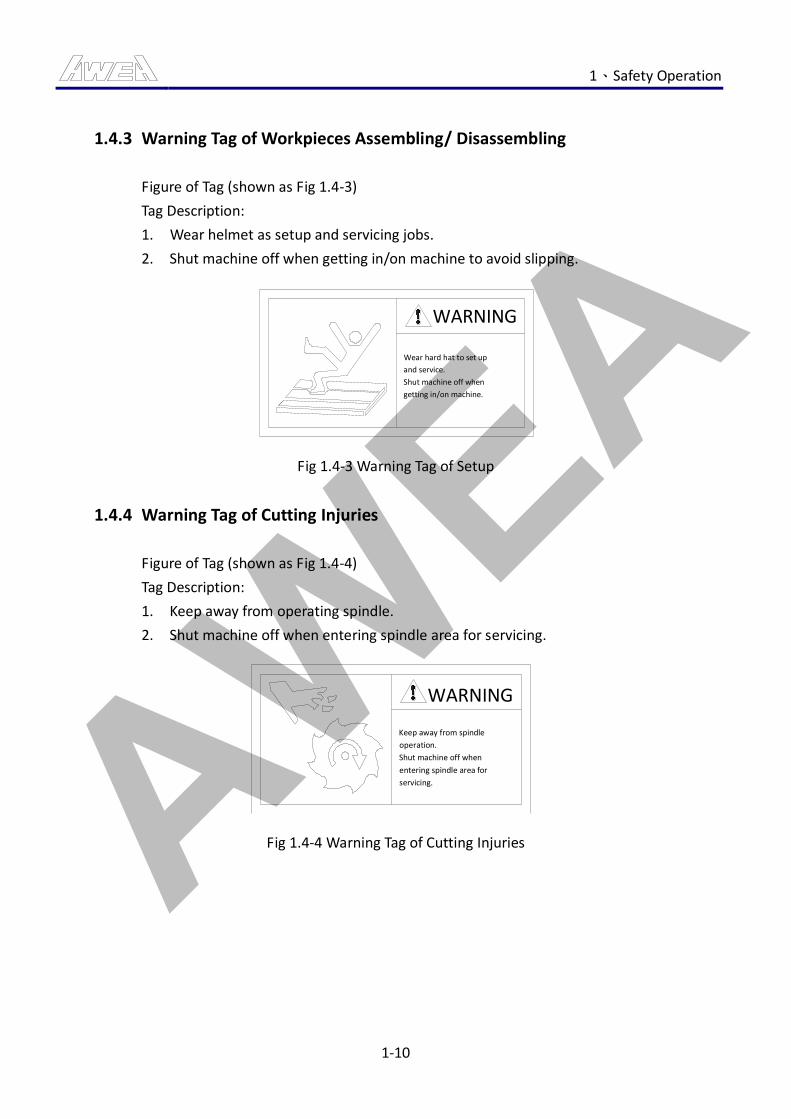
AWEA 1、Safety Operation
1-10
1.4.3 Warning Tag of Workpieces Assembling/ Disassembling
Figure of Tag (shown as Fig 1.4-3)
Tag Description:
1. Wear helmet as setup and servicing jobs.
2. Shut machine off when getting in/on machine to avoid slipping.
WARNING
Wear hard hat to set up
and service.
Shut machine off when
getting in/on machine.
Fig 1.4-3 Warning Tag of Setup
1.4.4 Warning Tag of Cutting Injuries
Figure of Tag (shown as Fig 1.4-4)
Tag Description:
1. Keep away from operating spindle.
2. Shut machine off when entering spindle area for servicing.
WARNING
Keep away from spindle
operation.
Shut machine off when
entering spindle area for
servicing.
Fig 1.4-4 Warning Tag of Cutting Injuries
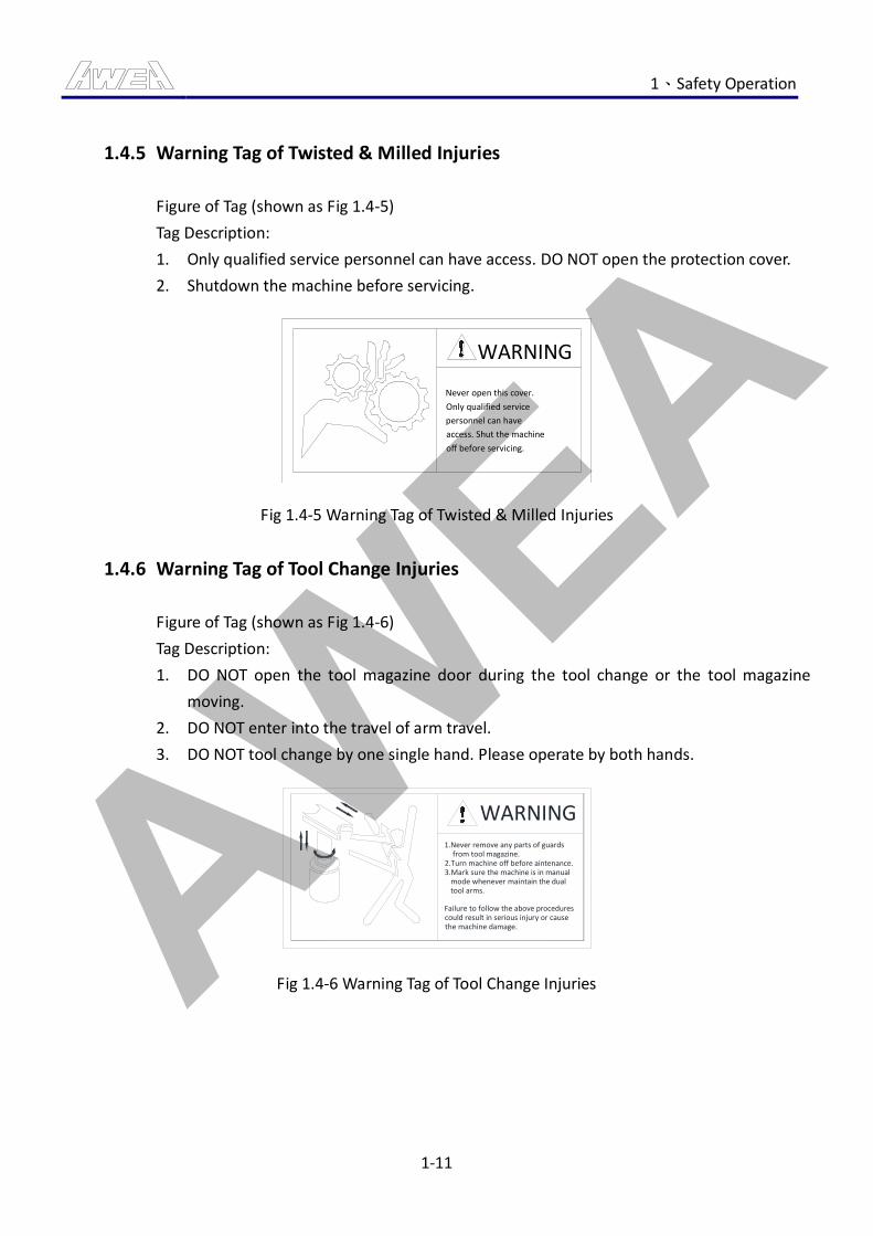
AWEA 1、Safety Operation
1-11
1.4.5 Warning Tag of Twisted & Milled Injuries
Figure of Tag (shown as Fig 1.4-5)
Tag Description:
1. Only qualified service personnel can have access. DO NOT open the protection cover.
2. Shutdown the machine before servicing.
WARNING
Never open this cover.
Only qualified service
personnel can have
access. Shut the machine
off before servicing.
Fig 1.4-5 Warning Tag of Twisted & Milled Injuries
1.4.6 Warning Tag of Tool Change Injuries
Figure of Tag (shown as Fig 1.4-6)
Tag Description:
1. DO NOT open the tool magazine door during the tool change or the tool magazine
moving.
2. DO NOT enter into the travel of arm travel.
3. DO NOT tool change by one single hand. Please operate by both hands.
WARNING1.Never remove any parts of guards from tool magazine.2.Turn machine off before aintenance.3.Mark sure the machine is in manual mode whenever maintain the dual tool arms.
Failure to follow the above procedurescould result in serious injury or causethe machine damage.
Fig 1.4-6 Warning Tag of Tool Change Injuries
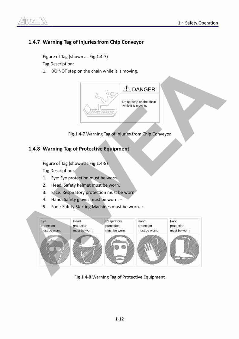
AWEA 1、Safety Operation
1-12
1.4.7 Warning Tag of Injuries from Chip Conveyor
Figure of Tag (shown as Fig 1.4-7)
Tag Description:
1. DO NOT step on the chain while it is moving.
DANGER
Do not step on the chain
while it is moving.
Fig 1.4-7 Warning Tag of Injuries from Chip Conveyor
1.4.8 Warning Tag of Protective Equipment
Figure of Tag (shown as Fig 1.4-8)
Tag Description:
1. Eye: Eye protection must be worn.
2. Head: Safety helmet must be worn.
3. Face: Respiratory protection must be worn.
4. Hand: Safety gloves must be worn.。
5. Foot: Safety Starting Machines must be worn.。
Eye
protection
must be worn.
Head Respiratory Hand Foot
protection
must be worn.
protection
must be worn.
protection
must be worn.
protection
must be worn.
Fig 1.4-8 Warning Tag of Protective Equipment
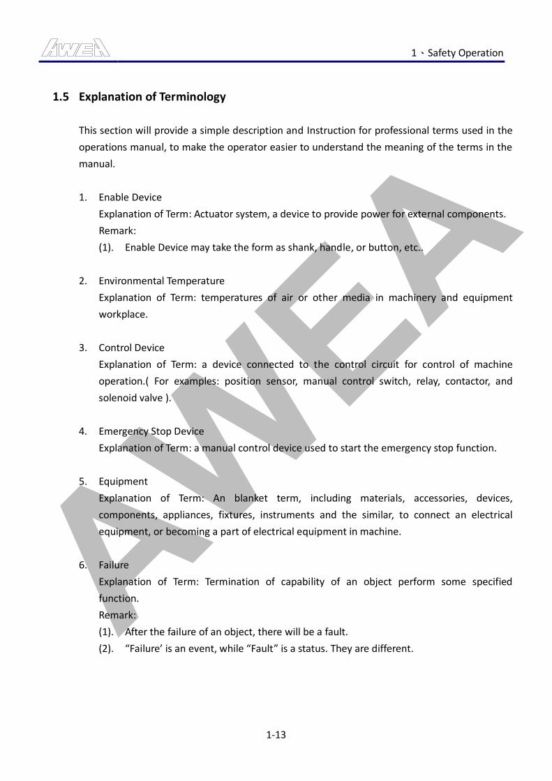
AWEA 1、Safety Operation
1-13
1.5 Explanation of Terminology
This section will provide a simple description and Instruction for professional terms used in the
operations manual, to make the operator easier to understand the meaning of the terms in the
manual.
1. Enable Device
Explanation of Term: Actuator system, a device to provide power for external components.
Remark:
(1). Enable Device may take the form as shank, handle, or button, etc..
2. Environmental Temperature
Explanation of Term: temperatures of air or other media in machinery and equipment
workplace.
3. Control Device
Explanation of Term: a device connected to the control circuit for control of machine
operation.( For examples: position sensor, manual control switch, relay, contactor, and
solenoid valve ).
4. Emergency Stop Device
Explanation of Term: a manual control device used to start the emergency stop function.
5. Equipment
Explanation of Term: An blanket term, including materials, accessories, devices,
components, appliances, fixtures, instruments and the similar, to connect an electrical
equipment, or becoming a part of electrical equipment in machine.
6. Failure
Explanation of Term: Termination of capability of an object perform some specified
function.
Remark:
(1). After the failure of an object, there will be a fault.
(2). “Failure’ is an event, while “Fault” is a status. They are different.
AWEA 1、Safety Operation
1-14
7. Fault
Explanation of Term: An object under the status of incapability to perform some specified
function.
Remark:
(1). The Fault is often the result of an object's own failure, but it may possibly exist
without to have a failure first.
8. Danger
Explanation of Term: The source possibly leads to injuries or damage to health.
Remark:
(1). These dangers can be limited to define its source (such as mechanical danger,
electrical danger) or the nature of potential danger (such electric shock danger,
cutting danger, toxic danger and fire danger).
(2). These hypothetical dangers are defined as follows:
During the expected usage period of machines, whether continuous or present
(For examples: the dangerous moved of moving components, the adverse physical
and psychological posture, noise divergence, and high temperature);
Or non-expected emergence
(For examples: explosion, squeezing danger after start non-intentionally, injection
after damaged)
9. Safety Interlock
Explanation of Term: An arrangement to interconnect the protective equipments, devices
and control systems or the electric power in all or part distributed to the machine.
10. Machine
Explanation of Term: Combination by many components, wherein including at least one can
move, can be adapted to the power circuit as a specific application, in particular, in the
combination formed for processing of a material.
11. Marking
Explanation of Term: the symbol or nameplate in the purpose to identify the equipment,
parts or devices, which can include the appropriate characteristics.
12. Overload
Explanation of Term: When the circuit is not in a fault condition, the time/current
relationship of circuit exceeds the rated full load of the circuit.
AWEA 1、Safety Operation
1-15
13. Technical Personnel
Explanation of Term: personnel with relevant training, education and experience, and able
to perceive risk and to avoid electrical dangers.
14. Suppliers
Explanation of Term: the party able to provide machinery equipment and services.
15. Operator
Explanation of Term: the party to use the machinery and equipment.
AWEA 1、Safety Operation
1-16
1.6 Safety Checks of Operation
CAUTION
Various checks must be done before starting each operation to ensure safety of use and normal
operation of machine.
1.6.1 Check before Starting Machine
Before starting the machine, check first if wires or cables on the machine are damaged in
order to avoid from electric shock accidents. Make sure to check if there is any damage.
Any leakage because of negligence to check will cause serious casualties of electric shock.
Other check points are as follows:
1. Position checked: Three-point combination.
Check items:
(1) Is coolant in the filter cup drained out?
(2) Is there sufficient oil in the oil cup?
(3) Is air compressed pressure sufficient?
Check method: Visual check.
2. Position checked: Machine spindle temperature control.
Check items:
(1) Is there sufficient oil in the spindle head?
(2) Are lubrication joints properly tightened?
Check method: Visual check, manual check.
3. Position checked: Tank, chip conveyor.
Check items:
(1) Are chips cleared?
(2) Is there sufficient coolant in the tank?
(3) Are the pipe joints properly tightened?
(4) Are the cable connectors tightened?
Check method: Visual check, manual check.
AWEA 1、Safety Operation
1-17
4. Position checked: Around the tank.
Check items:
(1) Are chips cleared?
(2) Are there any other items?
Check method: Visual check.
5. Position checked: Cover.
Check items:
(1) Are there chips accumulated on the surface?
(2) Is there proper film lubrication on the surface?
Check method: Visual check.
6. Position checked: The top of tool magazine door.
Check items:
(1) Is the accumulation of chips cleared?
Check method: Visual check.
7. Position checked: Console.
Check items:
(1) Is the accumulation of chips cleared?
Check method: Visual check.
8. Position checked: Spindle.
Check items:
(1) Is the spindle taper hole clean?
Check method: Visual check.
9. Position checked: Electrical cabinets, operation cabinets.
Check items:
(1) Are the control components or the connectors fixed?
(2) Is the access door closed?
Check method: Manual check.
10. Position checked: Various parts of the grounding wires.
Check items:
(1) Are the grounding terminals tighten?
Check method: Manual check.
AWEA 1、Safety Operation
1-18
11. Position checked: terminal boxes for tool magazine, base, crossbeam, and spindle
head etc.
Check items:
(1) Are the terminal screws and fittings tightened?
(2) Are the terminal box cover tightened?
Check method: Manual check.
12. Position checked: Machine around.
Check items:
(1) Are the door bolts are properly tightened?
(2) Is machine around clean?
Check method: Visual check, manual check.
AWEA 1、Safety Operation
1-19
1.6.2 Check after Starting Machine
1. Position checked: Motor.
Check items:
(1) Is there abnormal sound or overheated in motor?
Check method: Visual check, heard check.
2. Position checked: Air pressure unit.
Check items:
(1) Does the air pressure reach (5~7kg/cm^2)?
(2) Is there leak in air pipes?
Check method: Visual check, heard check.
3. Position checked: spindle temperature control machine.
Check items:
(1) Is the temperature settings correct?
(2) Is the operation of machine normally?
Check method: Visual check.
4. Position checked: LCD screen.
Check items:
(1) Are there any alarm messages displayed?
Check method: Visual check.
5. Position checked: Operator panel.
Check items:
(1) Is there any anomalies light on?
Check method: Visual check.
6. Position checked: Chip conveyor, Chip screw.
Check items:
(1) Is the CW movement correct?
(2) Is the CCW movement correct?
Check method: Visual check.
AWEA 1、Safety Operation
1-20
7. Position checked: Tank pump.
Check items:
(1) Is the tank pump in normal operation?
(2) Is there any leak in coolant pipes?
Check method: Visual check.
8. Position checked: Status indicator, three-color indicator.
Check items:
(1) Are the light bulbs damaged?
Check method: Visual check.
AWEA 1、Safety Operation
1-21
1.6.3 Manual Operation Check
Please refer to the Chapter of Operating Command; Check if following actions are normal?
If abnormal, contact the customer service staffs to resolve.
1. Position checked: Manual axial feed direction.
Check items:
(1) Is the feed (+) direction of each axis correct?
(2) Is the feed (-) direction of each axis correct?
Check method: Please refer to the Section of Operation Check in Chapter Manual Axial
Feed.
2. Position checked: Over travel protection.
Check items:
(1) Are the over travel protection and feed (+) direction of each axis correct?
(2) Are the over travel protection and feed (-) direction of each axis correct?
Check method: Please refer to the Section of Operation Check in Chapter Manual Axial
Feed.
3. Position checked: Manual HOME.
Check items:
(1) Is each axis able back to the reference point?
Check method: Please refer to the Section Manual HOME.
4. Position checked: The rotation direction of spindle.
Check items:
(1) Is the spindle CW direction normal?
(2) Is the spindle CCW direction normal?
(3) Is the spindle stop function normal?
(4) Is the spindle positioning function normal?
(5) Is the spindle tool release function normal?
Check method: Please refer to the Section of Operation Check in Chapter Manual
Spindle Operation, Positioning, and Tool Release.
AWEA 1、Safety Operation
1-22
5. Position checked: rotation direction of tool magazine.
Check items:
(1) Is the rotation direction (+) of tool magazine normal?
(2) Is the rotation direction (-) of tool magazine normal?
Check method: Please refer to the Section of Operation Check in Chapter Manual
Operation of Tool Magazine.
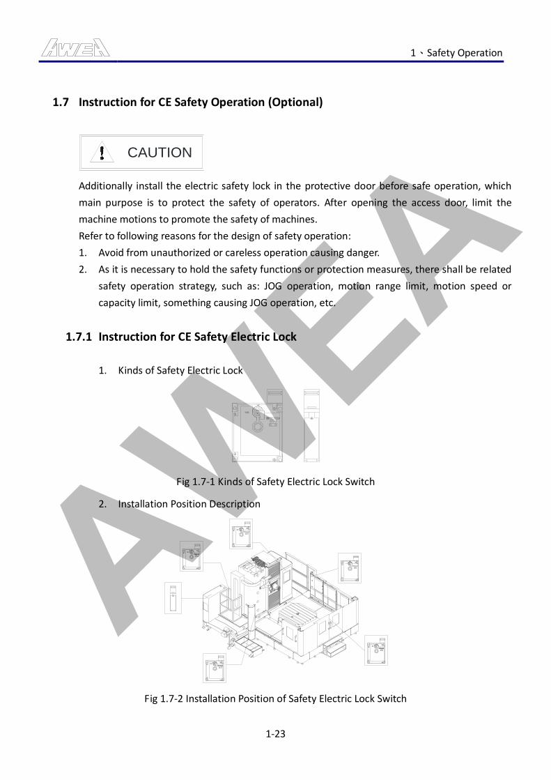
AWEA 1、Safety Operation
1-23
1.7 Instruction for CE Safety Operation (Optional)
CAUTION
Additionally install the electric safety lock in the protective door before safe operation, which
main purpose is to protect the safety of operators. After opening the access door, limit the
machine motions to promote the safety of machines.
Refer to following reasons for the design of safety operation:
1. Avoid from unauthorized or careless operation causing danger.
2. As it is necessary to hold the safety functions or protection measures, there shall be related
safety operation strategy, such as: JOG operation, motion range limit, motion speed or
capacity limit, something causing JOG operation, etc.
1.7.1 Instruction for CE Safety Electric Lock
1. Kinds of Safety Electric Lock
Fig 1.7-1 Kinds of Safety Electric Lock Switch
2. Installation Position Description
Fig 1.7-2 Installation Position of Safety Electric Lock Switch
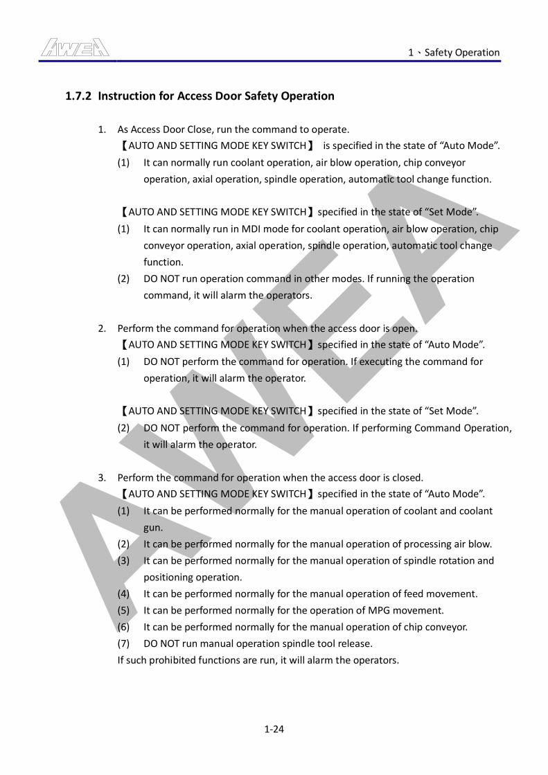
AWEA 1、Safety Operation
1-24
1.7.2 Instruction for Access Door Safety Operation
1. As Access Door Close, run the command to operate.
【AUTO AND SETTING MODE KEY SWITCH】 is specified in the state of “Auto Mode”.
(1) It can normally run coolant operation, air blow operation, chip conveyor
operation, axial operation, spindle operation, automatic tool change function.
【AUTO AND SETTING MODE KEY SWITCH】specified in the state of “Set Mode”.
(1) It can normally run in MDI mode for coolant operation, air blow operation, chip
conveyor operation, axial operation, spindle operation, automatic tool change
function.
(2) DO NOT run operation command in other modes. If running the operation
command, it will alarm the operators.
2. Perform the command for operation when the access door is open.
【AUTO AND SETTING MODE KEY SWITCH】specified in the state of “Auto Mode”.
(1) DO NOT perform the command for operation. If executing the command for
operation, it will alarm the operator.
【AUTO AND SETTING MODE KEY SWITCH】specified in the state of “Set Mode”.
(2) DO NOT perform the command for operation. If performing Command Operation,
it will alarm the operator.
3. Perform the command for operation when the access door is closed.
【AUTO AND SETTING MODE KEY SWITCH】specified in the state of “Auto Mode”.
(1) It can be performed normally for the manual operation of coolant and coolant
gun.
(2) It can be performed normally for the manual operation of processing air blow.
(3) It can be performed normally for the manual operation of spindle rotation and
positioning operation.
(4) It can be performed normally for the manual operation of feed movement.
(5) It can be performed normally for the operation of MPG movement.
(6) It can be performed normally for the manual operation of chip conveyor.
(7) DO NOT run manual operation spindle tool release.
If such prohibited functions are run, it will alarm the operators.
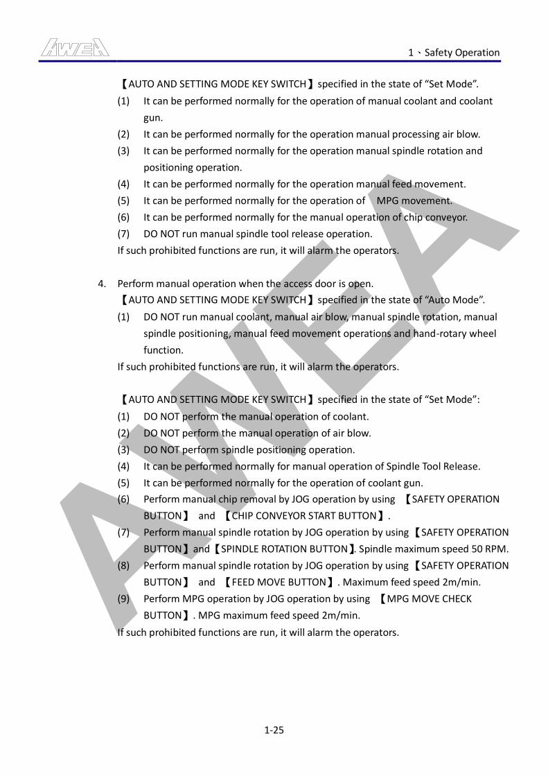
AWEA 1、Safety Operation
1-25
【AUTO AND SETTING MODE KEY SWITCH】specified in the state of “Set Mode”.
(1) It can be performed normally for the operation of manual coolant and coolant
gun.
(2) It can be performed normally for the operation manual processing air blow.
(3) It can be performed normally for the operation manual spindle rotation and
positioning operation.
(4) It can be performed normally for the operation manual feed movement.
(5) It can be performed normally for the operation of MPG movement.
(6) It can be performed normally for the manual operation of chip conveyor.
(7) DO NOT run manual spindle tool release operation.
If such prohibited functions are run, it will alarm the operators.
4. Perform manual operation when the access door is open.
【AUTO AND SETTING MODE KEY SWITCH】specified in the state of “Auto Mode”.
(1) DO NOT run manual coolant, manual air blow, manual spindle rotation, manual
spindle positioning, manual feed movement operations and hand-rotary wheel
function.
If such prohibited functions are run, it will alarm the operators.
【AUTO AND SETTING MODE KEY SWITCH】specified in the state of “Set Mode”:
(1) DO NOT perform the manual operation of coolant.
(2) DO NOT perform the manual operation of air blow.
(3) DO NOT perform spindle positioning operation.
(4) It can be performed normally for manual operation of Spindle Tool Release.
(5) It can be performed normally for the operation of coolant gun.
(6) Perform manual chip removal by JOG operation by using 【SAFETY OPERATION
BUTTON】 and 【CHIP CONVEYOR START BUTTON】.
(7) Perform manual spindle rotation by JOG operation by using 【SAFETY OPERATION
BUTTON】 and 【SPINDLE ROTATION BUTTON】. Spindle maximum speed 50 RPM.
(8) Perform manual spindle rotation by JOG operation by using 【SAFETY OPERATION
BUTTON】 and 【FEED MOVE BUTTON】. Maximum feed speed 2m/min.
(9) Perform MPG operation by JOG operation by using 【MPG MOVE CHECK
BUTTON】. MPG maximum feed speed 2m/min.
If such prohibited functions are run, it will alarm the operators.
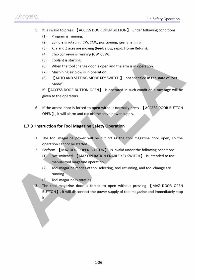
AWEA 1、Safety Operation
1-26
5. It is invalid to press 【ACCESS DOOR OPEN BUTTON】 under following conditions:
(1) Program is running.
(2) Spindle is rotating (CW, CCW, positioning, gear changing).
(3) X, Y and Z axes are moving (feed, slow, rapid, Home Return).
(4) Chip conveyor is running (CW, CCW).
(5) Coolant is starting.
(6) When the tool change door is open and the arm is in operation.
(7) Machining air blow is in operation.
(8) 【AUTO AND SETTING MODE KEY SWITCH】 not specified in the state of “Set
Mode”.
If 【ACCESS DOOR BUTTON OPEN】 is operated in such condition a message will be
given to the operators.
6. If the access door is forced to open without normally press 【ACCESS DOOR BUTTON
OPEN】, it will alarm and cut off the servo power supply.
1.7.3 Instruction for Tool Magazine Safety Operation
1. The tool magazine power will be cut off as the tool magazine door open, so the
operation cannot be started.
2. Perform 【MAZ DOOR OPEN BUTTON】 is invalid under the following conditions:
(1) Not switched 【MAZ OPERATION ENABLE KEY SWITCH】 is intended to use
manual tool magazine operation.
(2) Tool magazine modes of tool selecting, tool returning, and tool change are
running.
(3) Tool magazine is rotating.
3. The tool magazine door is forced to open without pressing 【MAZ DOOR OPEN
BUTTON】, it will disconnect the power supply of tool magazine and immediately stop
it.
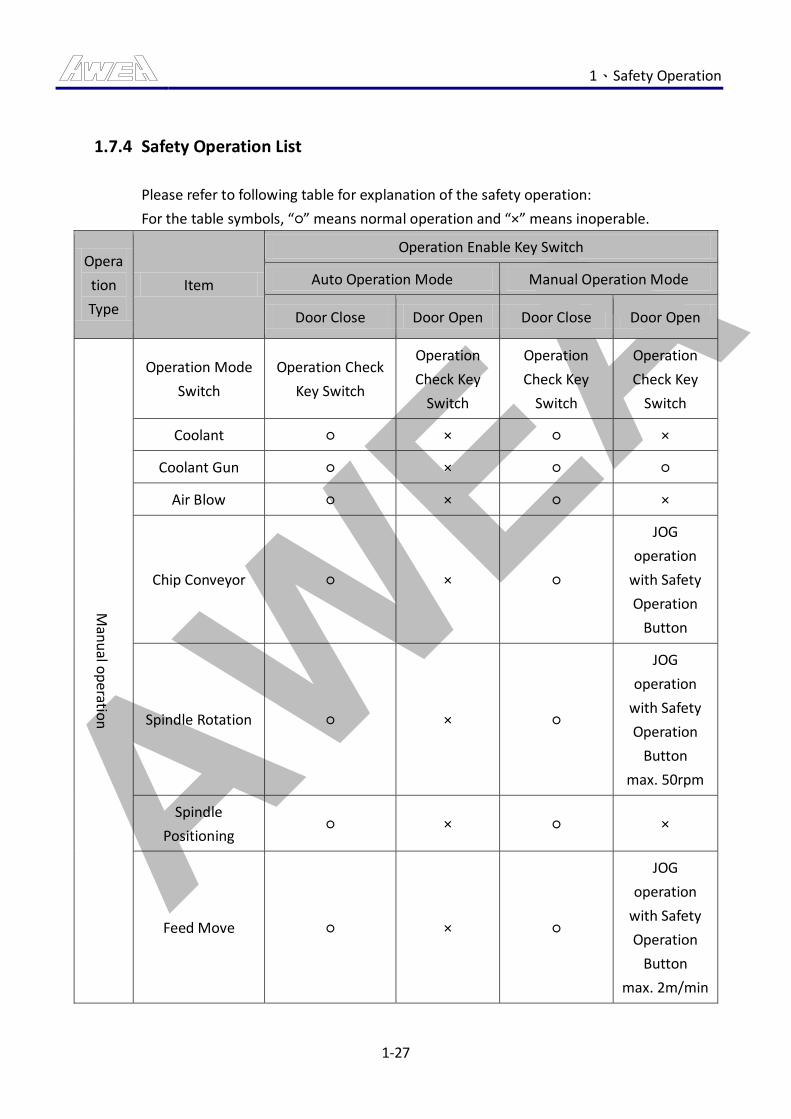
AWEA 1、Safety Operation
1-27
1.7.4 Safety Operation List
Please refer to following table for explanation of the safety operation:
For the table symbols, “○” means normal operation and “×” means inoperable.
Opera
tion
Type
Item
Operation Enable Key Switch
Auto Operation Mode Manual Operation Mode
Door Close Door Open Door Close Door Open
Man
ual o
peratio
n
Operation Mode
Switch
Operation Check
Key Switch
Operation
Check Key
Switch
Operation
Check Key
Switch
Operation
Check Key
Switch
Coolant ○ × ○ ×
Coolant Gun ○ × ○ ○
Air Blow ○ × ○ ×
Chip Conveyor ○ × ○
JOG
operation
with Safety
Operation
Button
Spindle Rotation ○ × ○
JOG
operation
with Safety
Operation
Button
max. 50rpm
Spindle
Positioning ○ × ○ ×
Feed Move ○ × ○
JOG
operation
with Safety
Operation
Button
max. 2m/min
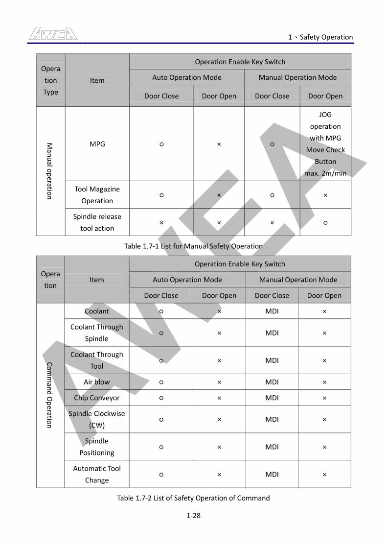
AWEA 1、Safety Operation
1-28
Opera
tion
Type
Item
Operation Enable Key Switch
Auto Operation Mode Manual Operation Mode
Door Close Door Open Door Close Door Open
Man
ual o
peratio
n
MPG ○ × ○
JOG
operation
with MPG
Move Check
Button
max. 2m/min
Tool Magazine
Operation ○ × ○ ×
Spindle release
tool action × × × ○
Table 1.7-1 List for Manual Safety Operation
Opera
tion Item
Operation Enable Key Switch
Auto Operation Mode Manual Operation Mode
Door Close Door Open Door Close Door Open
Co
mm
and
Op
eratio
n
Coolant ○ × MDI ×
Coolant Through
Spindle ○ × MDI ×
Coolant Through
Tool ○ × MDI ×
Air blow ○ × MDI ×
Chip Conveyor ○ × MDI ×
Spindle Clockwise
(CW) ○ × MDI ×
Spindle
Positioning ○ × MDI ×
Automatic Tool
Change ○ × MDI ×
Table 1.7-2 List of Safety Operation of Command
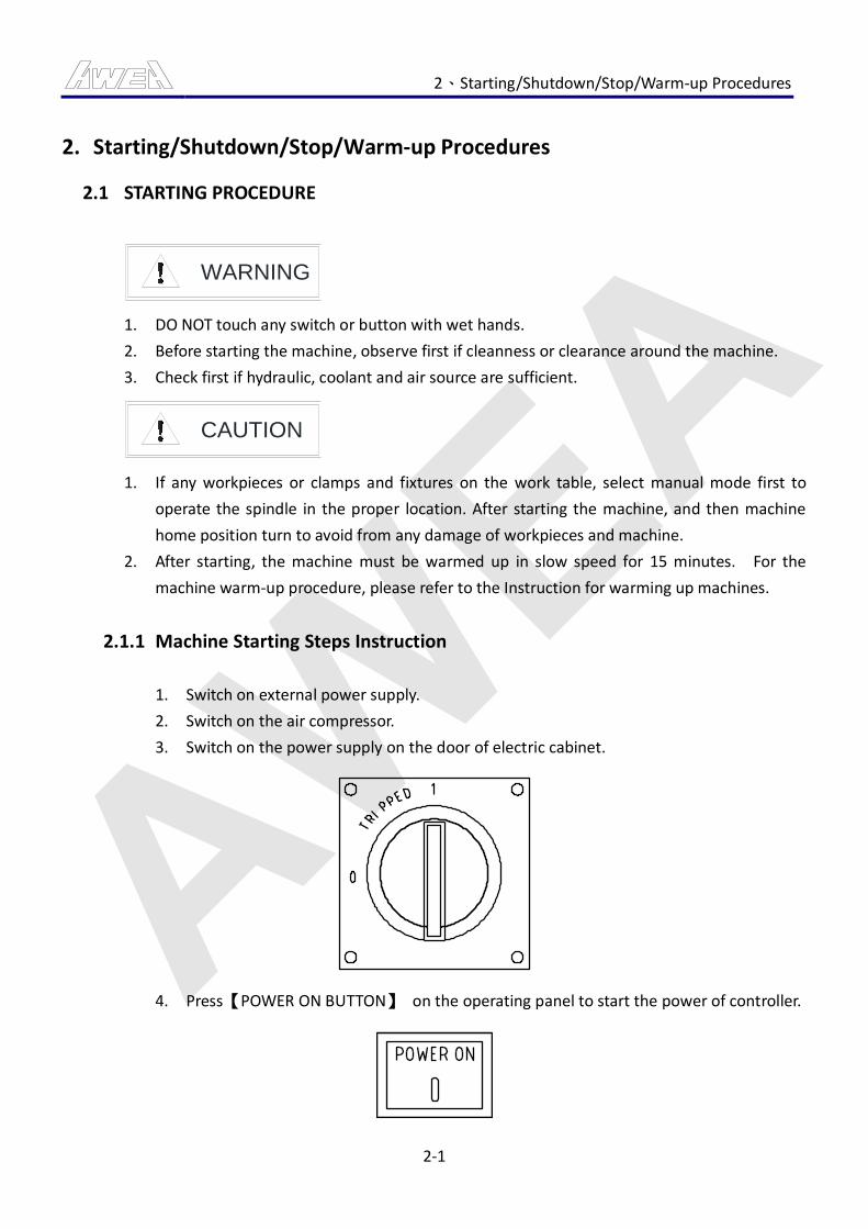
AWEA 2、Starting/Shutdown/Stop/Warm-up Procedures
2-1
2. Starting/Shutdown/Stop/Warm-up Procedures
2.1 STARTING PROCEDURE
WARNING
1. DO NOT touch any switch or button with wet hands.
2. Before starting the machine, observe first if cleanness or clearance around the machine.
3. Check first if hydraulic, coolant and air source are sufficient.
CAUTION
1. If any workpieces or clamps and fixtures on the work table, select manual mode first to
operate the spindle in the proper location. After starting the machine, and then machine
home position turn to avoid from any damage of workpieces and machine.
2. After starting, the machine must be warmed up in slow speed for 15 minutes. For the
machine warm-up procedure, please refer to the Instruction for warming up machines.
2.1.1 Machine Starting Steps Instruction
1. Switch on external power supply.
2. Switch on the air compressor.
3. Switch on the power supply on the door of electric cabinet.
4. Press【POWER ON BUTTON】 on the operating panel to start the power of controller.
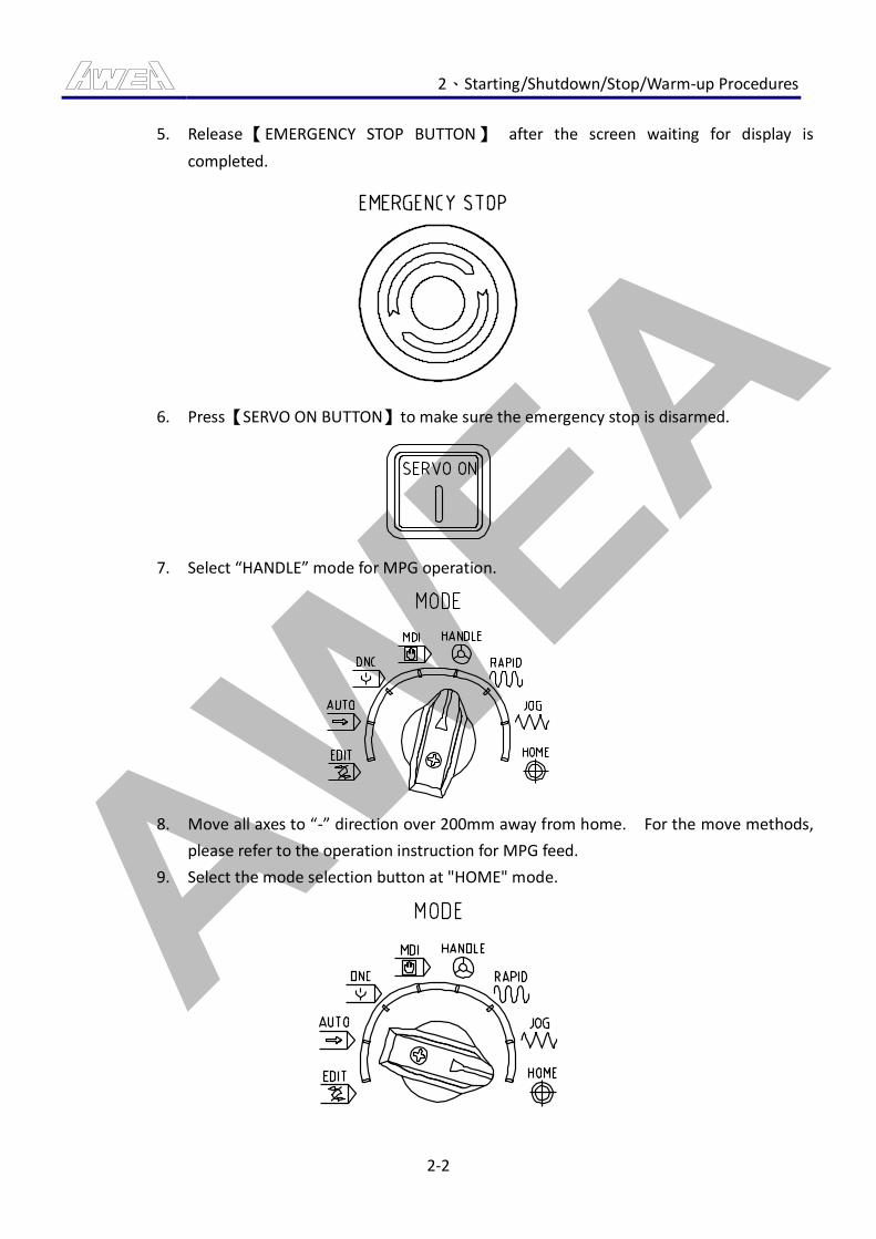
AWEA 2、Starting/Shutdown/Stop/Warm-up Procedures
2-2
5. Release【EMERGENCY STOP BUTTON】 after the screen waiting for display is
completed.
6. Press【SERVO ON BUTTON】to make sure the emergency stop is disarmed.
7. Select “HANDLE” mode for MPG operation.
8. Move all axes to “-” direction over 200mm away from home. For the move methods,
please refer to the operation instruction for MPG feed.
9. Select the mode selection button at "HOME" mode.
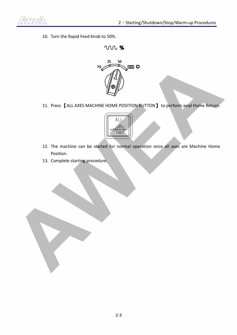
AWEA 2、Starting/Shutdown/Stop/Warm-up Procedures
2-3
10. Turn the Rapid Feed Knob to 50%.
11. Press 【ALL AXES MACHINE HOME POSITION BUTTON】 to perform axial Home Return.
12. The machine can be started for normal operation once all axes are Machine Home
Position.
13. Complete starting procedure.

AWEA 2、Starting/Shutdown/Stop/Warm-up Procedures
2-4
2.2 Shutdown Procedure
CAUTION
1. After shutting down, lock the main power switch on the electrical cabinet to prevent from
Starting Machine by others at free.
2. After shutting down, DO NOT leave the key of lock or switch still inserted in.
2.2.1 Machine Shutdown Steps Instruction
1. Select the mode selection button at “HOME” mode.
2. Turn the Rapid Feed Knob to 50%.
3. Press 【ALL AXES MACHINE HOME POSITION BUTTON】 to perform axial Home Return.
4. Wait until all axes are back to the mechanical home position.
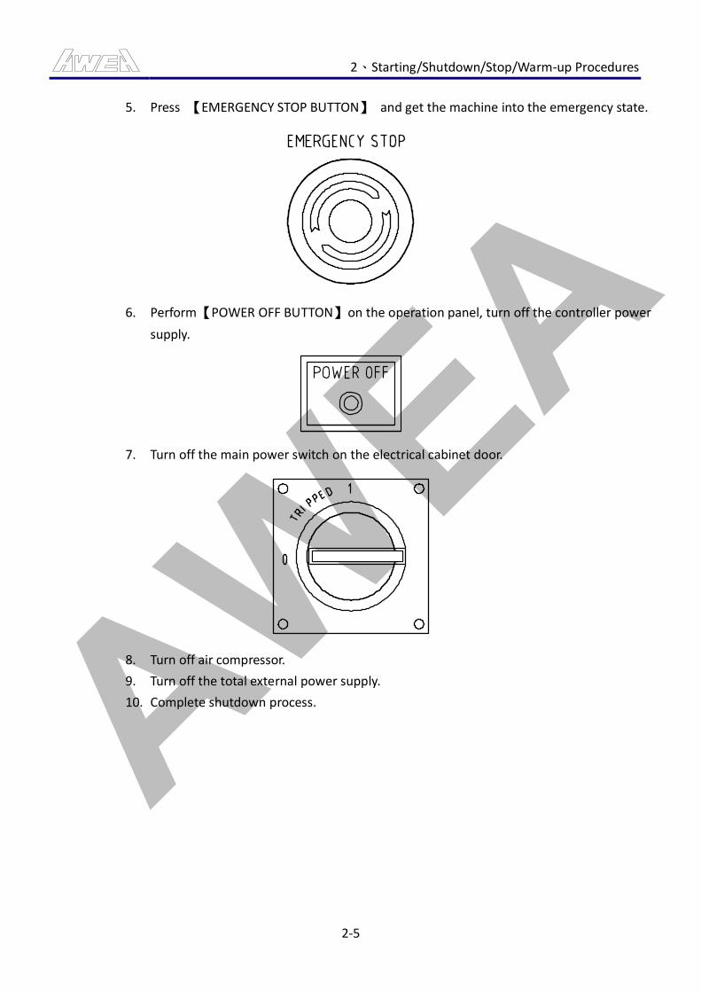
AWEA 2、Starting/Shutdown/Stop/Warm-up Procedures
2-5
5. Press 【EMERGENCY STOP BUTTON】 and get the machine into the emergency state.
6. Perform 【POWER OFF BUTTON】 on the operation panel, turn off the controller power
supply.
7. Turn off the main power switch on the electrical cabinet door.
8. Turn off air compressor.
9. Turn off the total external power supply.
10. Complete shutdown process.
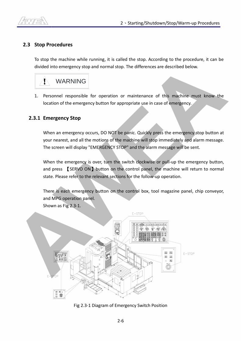
AWEA 2、Starting/Shutdown/Stop/Warm-up Procedures
2-6
2.3 Stop Procedures
To stop the machine while running, it is called the stop. According to the procedure, it can be
divided into emergency stop and normal stop. The differences are described below.
WARNING
1. Personnel responsible for operation or maintenance of this machine must know the
location of the emergency button for appropriate use in case of emergency.
2.3.1 Emergency Stop
When an emergency occurs, DO NOT be panic. Quickly press the emergency stop button at
your nearest, and all the motions of the machine will stop immediately and alarm message.
The screen will display "EMERGENCY STOP" and the alarm message will be sent.
When the emergency is over, turn the switch clockwise or pull-up the emergency button,
and press 【SERVO ON】button on the control panel, the machine will return to normal
state. Please refer to the relevant sections for the follow-up operation.
There is each emergency button on the control box, tool magazine panel, chip conveyor,
and MPG operation panel.
Shown as Fig 2.3-1.
Fig 2.3-1 Diagram of Emergency Switch Position

AWEA 2、Starting/Shutdown/Stop/Warm-up Procedures
2-7
2.3.2 Normal Stop
To stop or hold the machine in operation, there are two methods as the following:
1. Program stop (M00)
Stop auto operation after the signal block of the program including M00. Stop the
program same as the signal block operation. All the processing conditions remain
unchanged.
2. Selective stop (M01)
Similar to M00, stop the operation after the execution of signal block operation
including M01.
3. Program End (M02, M30)
Enter M02 or M30 at the last signal block to end the program. Whenever the execution
of the last signal block is completed, the machine will stop all motions and the program
will make ending lights on. If the last signal block is M30 or M02, the indicators on the
screen will automatically return to the cycle start, which means the program is ready to
restart. And the program end lights will be blinking.
4. Signal Block Operation Button (shown as Fig 2.3-2)
Function: This is the function to stop the machine after the program executing the
signal block.
Button Description:
In the automatic processing program under "Auto" or "MDI" mode, after pressing
the button, the program will only carry out one signal block with 【CYCLE START
BUTTON】. For next signal block, please perform 【CYCLE START BUTTON】 again.
Action Description:
(1) For G28 and G30, function of the signal block stops in the mid-point.
(2) The end point for fixed cycle signal block is at the end of 1, 2 and 6 as shown
below. When the functions of point 1 or 2 are working, the feed hold light will
turn on.
(3) The suspension of signal block does not include M98P; M99; and G65.However, if
the signal block includes the address other than O, N or P, the signal block
command will stop even in M98P or M99.
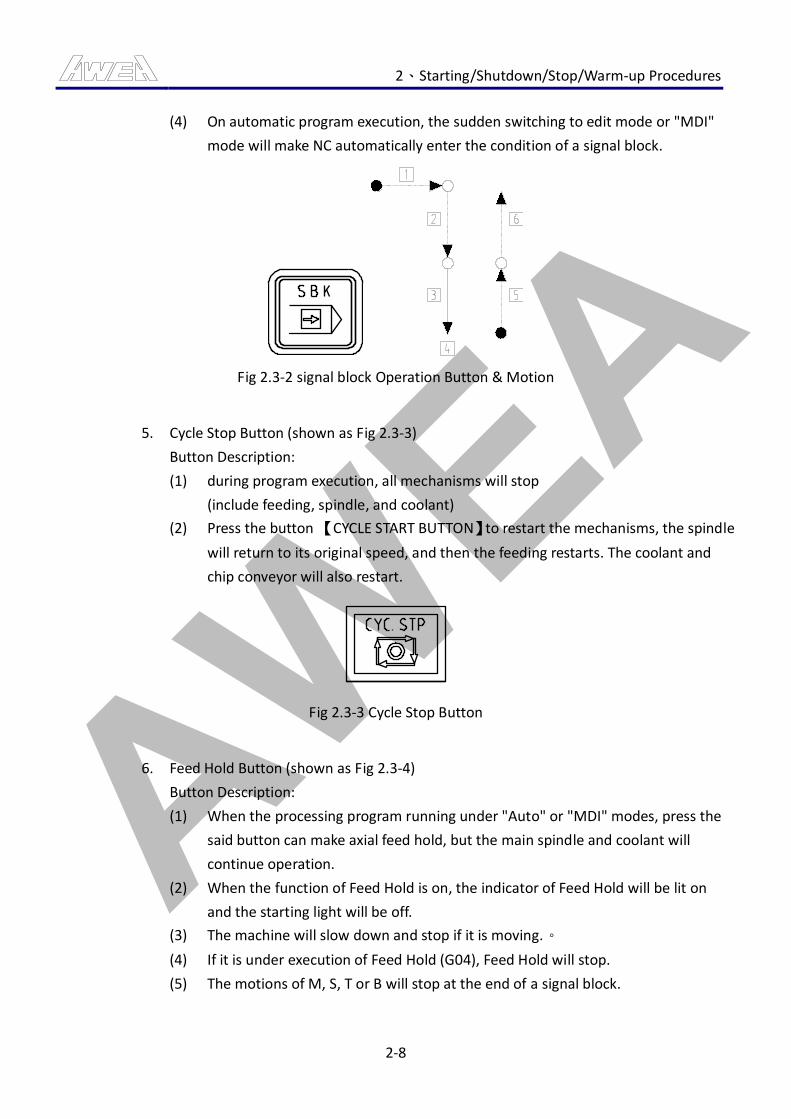
AWEA 2、Starting/Shutdown/Stop/Warm-up Procedures
2-8
(4) On automatic program execution, the sudden switching to edit mode or "MDI"
mode will make NC automatically enter the condition of a signal block.
Fig 2.3-2 signal block Operation Button & Motion
5. Cycle Stop Button (shown as Fig 2.3-3)
Button Description:
(1) during program execution, all mechanisms will stop
(include feeding, spindle, and coolant)
(2) Press the button 【CYCLE START BUTTON】to restart the mechanisms, the spindle
will return to its original speed, and then the feeding restarts. The coolant and
chip conveyor will also restart.
Fig 2.3-3 Cycle Stop Button
6. Feed Hold Button (shown as Fig 2.3-4)
Button Description:
(1) When the processing program running under "Auto" or "MDI" modes, press the
said button can make axial feed hold, but the main spindle and coolant will
continue operation.
(2) When the function of Feed Hold is on, the indicator of Feed Hold will be lit on
and the starting light will be off.
(3) The machine will slow down and stop if it is moving.。
(4) If it is under execution of Feed Hold (G04), Feed Hold will stop.
(5) The motions of M, S, T or B will stop at the end of a signal block.
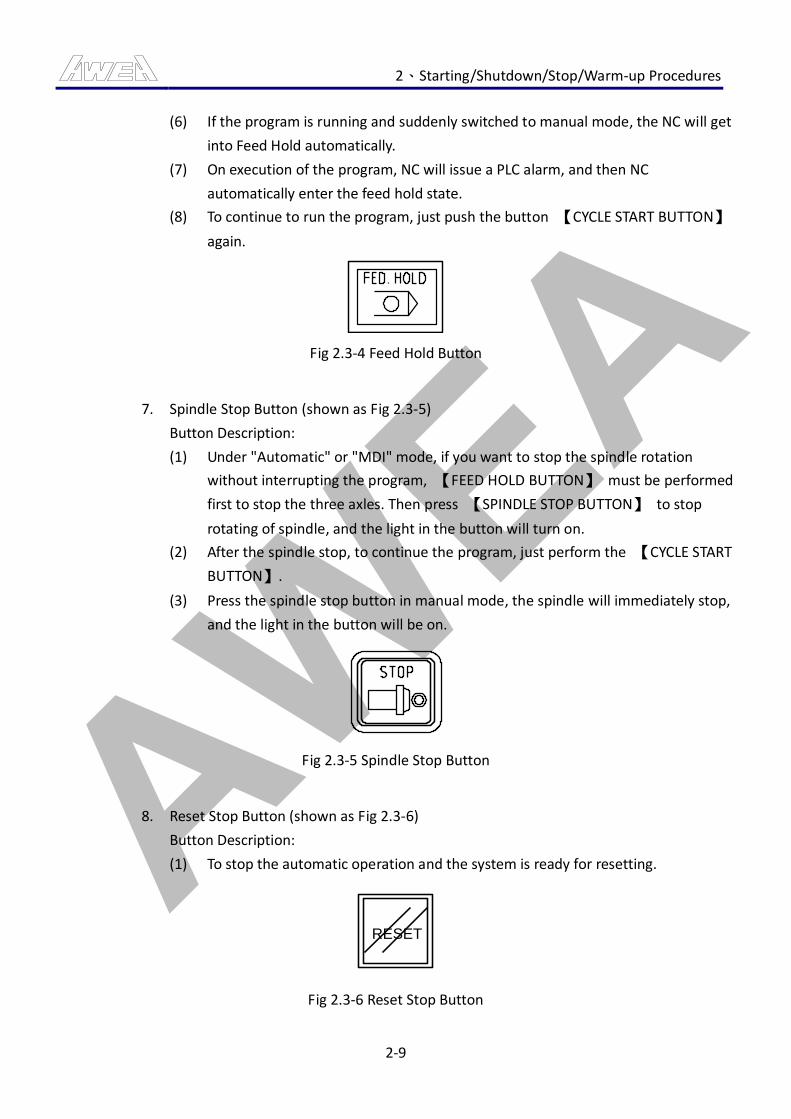
AWEA 2、Starting/Shutdown/Stop/Warm-up Procedures
2-9
(6) If the program is running and suddenly switched to manual mode, the NC will get
into Feed Hold automatically.
(7) On execution of the program, NC will issue a PLC alarm, and then NC
automatically enter the feed hold state.
(8) To continue to run the program, just push the button 【CYCLE START BUTTON】
again.
Fig 2.3-4 Feed Hold Button
7. Spindle Stop Button (shown as Fig 2.3-5)
Button Description:
(1) Under "Automatic" or "MDI" mode, if you want to stop the spindle rotation
without interrupting the program, 【FEED HOLD BUTTON】 must be performed
first to stop the three axles. Then press 【SPINDLE STOP BUTTON】 to stop
rotating of spindle, and the light in the button will turn on.
(2) After the spindle stop, to continue the program, just perform the 【CYCLE START
BUTTON】.
(3) Press the spindle stop button in manual mode, the spindle will immediately stop,
and the light in the button will be on.
Fig 2.3-5 Spindle Stop Button
8. Reset Stop Button (shown as Fig 2.3-6)
Button Description:
(1) To stop the automatic operation and the system is ready for resetting.
RESET
Fig 2.3-6 Reset Stop Button
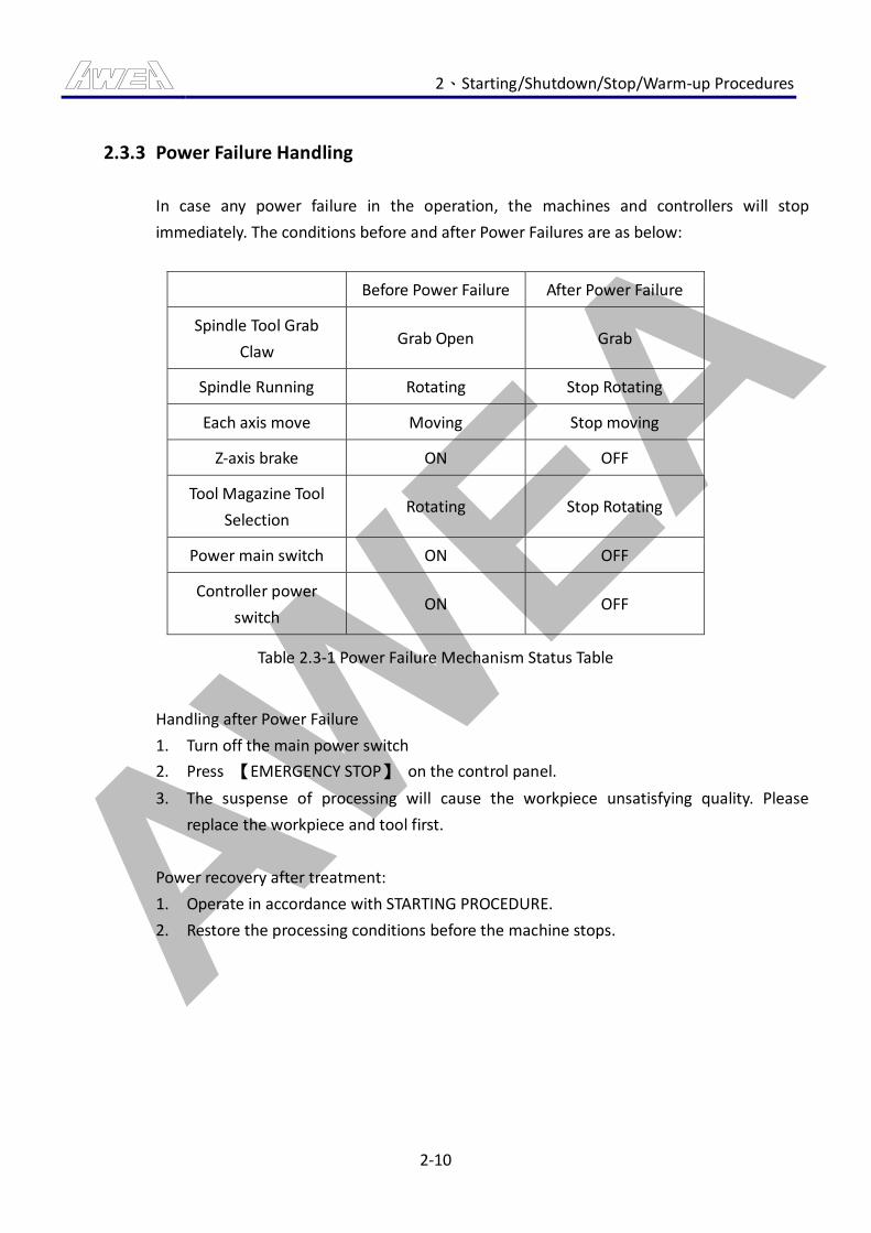
AWEA 2、Starting/Shutdown/Stop/Warm-up Procedures
2-10
2.3.3 Power Failure Handling
In case any power failure in the operation, the machines and controllers will stop
immediately. The conditions before and after Power Failures are as below:
Before Power Failure After Power Failure
Spindle Tool Grab
Claw Grab Open Grab
Spindle Running Rotating Stop Rotating
Each axis move Moving Stop moving
Z-axis brake ON OFF
Tool Magazine Tool
Selection Rotating Stop Rotating
Power main switch ON OFF
Controller power
switch ON OFF
Table 2.3-1 Power Failure Mechanism Status Table
Handling after Power Failure
1. Turn off the main power switch
2. Press 【EMERGENCY STOP】 on the control panel.
3. The suspense of processing will cause the workpiece unsatisfying quality. Please
replace the workpiece and tool first.
Power recovery after treatment:
1. Operate in accordance with STARTING PROCEDURE.
2. Restore the processing conditions before the machine stops.
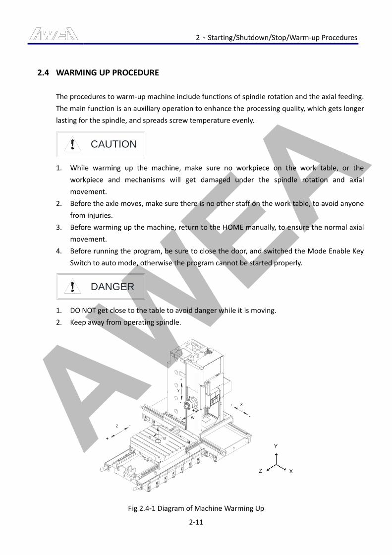
AWEA 2、Starting/Shutdown/Stop/Warm-up Procedures
2-11
2.4 WARMING UP PROCEDURE
The procedures to warm-up machine include functions of spindle rotation and the axial feeding.
The main function is an auxiliary operation to enhance the processing quality, which gets longer
lasting for the spindle, and spreads screw temperature evenly.
CAUTION
1. While warming up the machine, make sure no workpiece on the work table, or the
workpiece and mechanisms will get damaged under the spindle rotation and axial
movement.
2. Before the axle moves, make sure there is no other staff on the work table, to avoid anyone
from injuries.
3. Before warming up the machine, return to the HOME manually, to ensure the normal axial
movement.
4. Before running the program, be sure to close the door, and switched the Mode Enable Key
Switch to auto mode, otherwise the program cannot be started properly.
DANGER
1. DO NOT get close to the table to avoid danger while it is moving.
2. Keep away from operating spindle.
X
-
+
+
-
Y
Z -
+
W-
+
B
Y
Z X
Fig 2.4-1 Diagram of Machine Warming Up
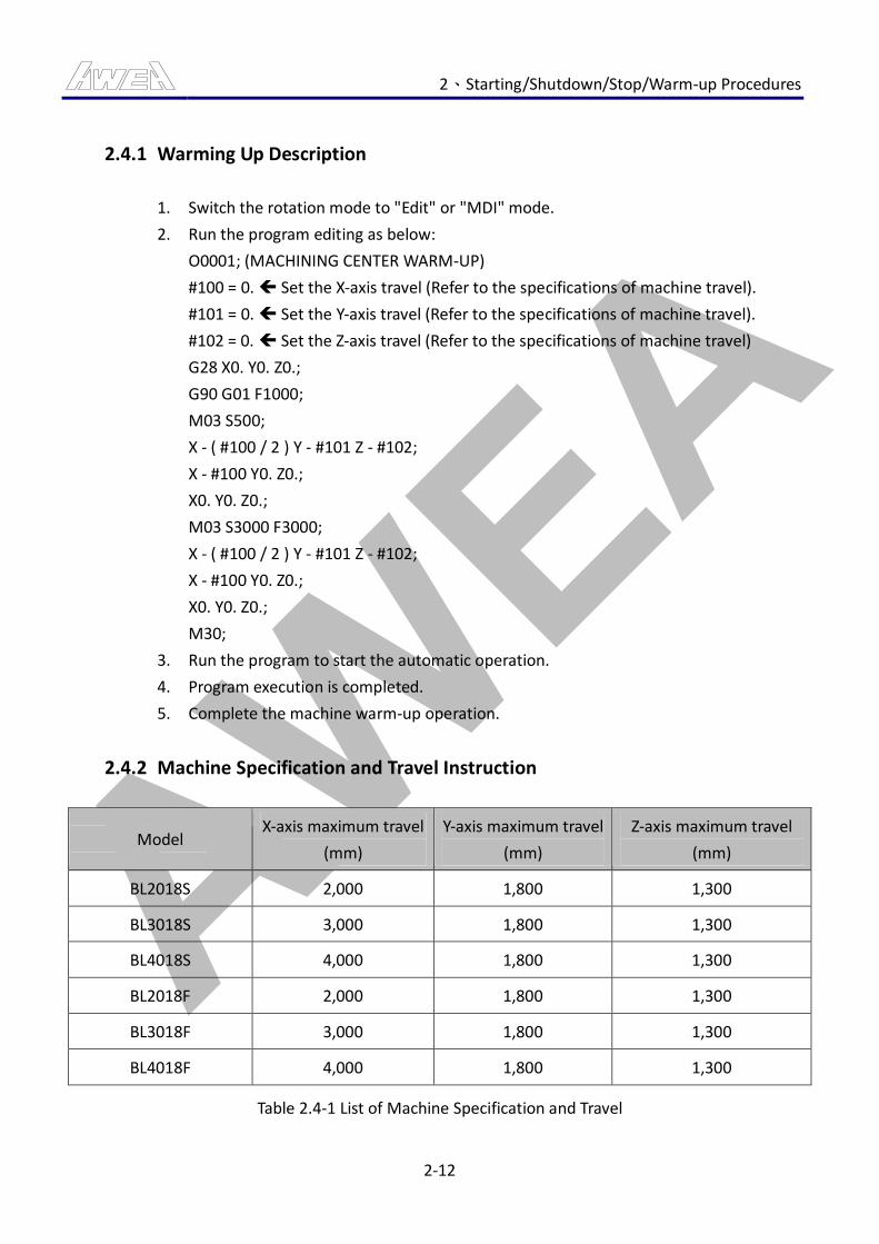
AWEA 2、Starting/Shutdown/Stop/Warm-up Procedures
2-12
2.4.1 Warming Up Description
1. Switch the rotation mode to "Edit" or "MDI" mode.
2. Run the program editing as below:
O0001; (MACHINING CENTER WARM-UP)
#100 = 0. Set the X-axis travel (Refer to the specifications of machine travel).
#101 = 0. Set the Y-axis travel (Refer to the specifications of machine travel).
#102 = 0. Set the Z-axis travel (Refer to the specifications of machine travel)
G28 X0. Y0. Z0.;
G90 G01 F1000;
M03 S500;
X - ( #100 / 2 ) Y - #101 Z - #102;
X - #100 Y0. Z0.;
X0. Y0. Z0.;
M03 S3000 F3000;
X - ( #100 / 2 ) Y - #101 Z - #102;
X - #100 Y0. Z0.;
X0. Y0. Z0.;
M30;
3. Run the program to start the automatic operation.
4. Program execution is completed.
5. Complete the machine warm-up operation.
2.4.2 Machine Specification and Travel Instruction
Model X-axis maximum travel
(mm)
Y-axis maximum travel
(mm)
Z-axis maximum travel
(mm)
BL2018S 2,000 1,800 1,300
BL3018S 3,000 1,800 1,300
BL4018S 4,000 1,800 1,300
BL2018F 2,000 1,800 1,300
BL3018F 3,000 1,800 1,300
BL4018F 4,000 1,800 1,300
Table 2.4-1 List of Machine Specification and Travel

AWEA 3、Operation Panel Instruction
3-1
3. Operation Panel Instruction
CAUTION
This section describes the control panel on AWEA machine, including all the buttons, knobs, and
lights significance. Please read this section to ensure proper use of button functions, and correct
judgment of light significance.
3.1 Operation Panel of Machine
Fig 3.1-1 Operation Panel of Machine
3.1.1 Machine Panel Instruction
1. Emergency Stop Button (shown as Fig 3.1-2 )
Functional Description:
(1) After the button is pressed, the machine will immediately stop all the motions
and reset the NC data. To release the state of emergency, the factors must be
removed first. Pull up the emergency button, and then press 【SERVO ON】, to
relieve the emergency.
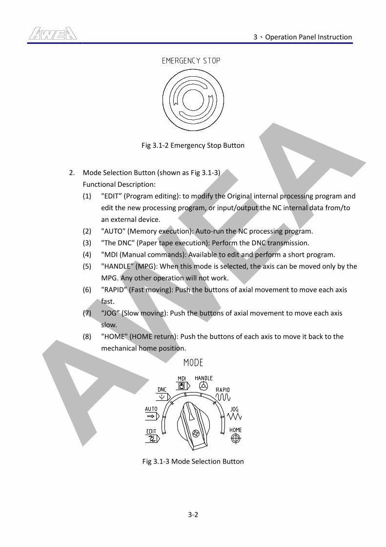
AWEA 3、Operation Panel Instruction
3-2
Fig 3.1-2 Emergency Stop Button
2. Mode Selection Button (shown as Fig 3.1-3)
Functional Description:
(1) "EDIT” (Program editing): to modify the Original internal processing program and
edit the new processing program, or input/output the NC internal data from/to
an external device.
(2) "AUTO" (Memory execution): Auto-run the NC processing program.
(3) "The DNC" (Paper tape execution): Perform the DNC transmission.
(4) "MDI (Manual commands): Available to edit and perform a short program.
(5) "HANDLE” (MPG): When this mode is selected, the axis can be moved only by the
MPG. Any other operation will not work.
(6) "RAPID” (Fast moving): Push the buttons of axial movement to move each axis
fast.
(7) “JOG” (Slow moving): Push the buttons of axial movement to move each axis
slow.
(8) "HOME" (HOME return): Push the buttons of each axis to move it back to the
mechanical home position.
Fig 3.1-3 Mode Selection Button
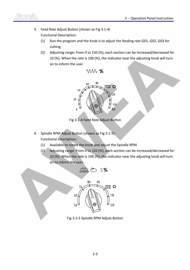
AWEA 3、Operation Panel Instruction
3-3
3. Feed Rate Adjust Button (shown as Fig 3.1-4)
Functional Description:
(1) Run the program and the knob is to adjust the feeding rate G01, G02, G03 for
cutting.
(2) Adjusting range: From 0 to 150 (%), each section can be increased/decreased for
10 (%). When the rate is 100 (%), the indicator near the adjusting knob will turn
on to inform the user.
Fig 3.1-4 Feed Rate Adjust Button
4. Spindle RPM Adjust Button (shown as Fig 3.1-5)
Functional Description:
(1) Available to rotate the knob and adjust the Spindle RPM.
(2) Adjusting range: From 0 to 120 (%), each section can be increased/decreased for
10 (%). When the rate is 100 (%), the indicator near the adjusting knob will turn
on to inform the user.
Fig 3.1-5 Spindle RPM Adjust Button
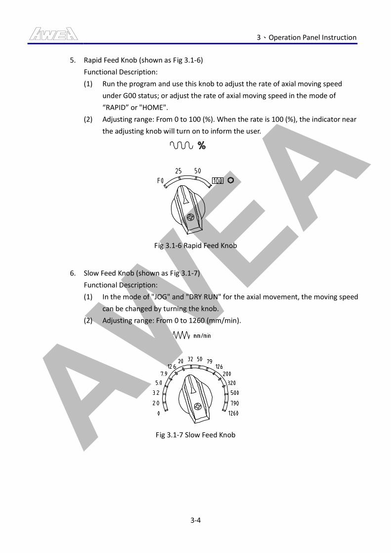
AWEA 3、Operation Panel Instruction
3-4
5. Rapid Feed Knob (shown as Fig 3.1-6)
Functional Description:
(1) Run the program and use this knob to adjust the rate of axial moving speed
under G00 status; or adjust the rate of axial moving speed in the mode of
“RAPID” or "HOME".
(2) Adjusting range: From 0 to 100 (%). When the rate is 100 (%), the indicator near
the adjusting knob will turn on to inform the user.
Fig 3.1-6 Rapid Feed Knob
6. Slow Feed Knob (shown as Fig 3.1-7)
Functional Description:
(1) In the mode of "JOG" and "DRY RUN" for the axial movement, the moving speed
can be changed by turning the knob.
(2) Adjusting range: From 0 to 1260 (mm/min).
Fig 3.1-7 Slow Feed Knob
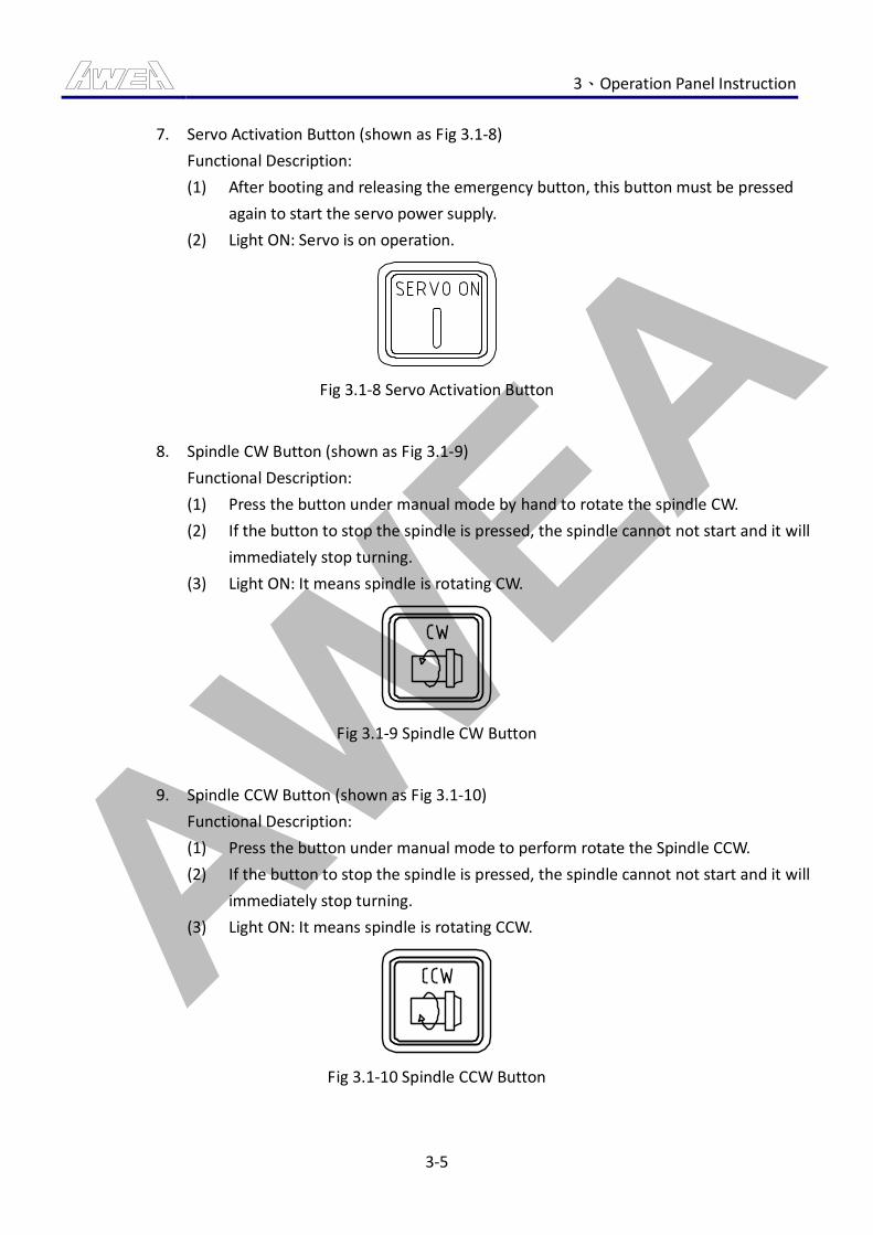
AWEA 3、Operation Panel Instruction
3-5
7. Servo Activation Button (shown as Fig 3.1-8)
Functional Description:
(1) After booting and releasing the emergency button, this button must be pressed
again to start the servo power supply.
(2) Light ON: Servo is on operation.
Fig 3.1-8 Servo Activation Button
8. Spindle CW Button (shown as Fig 3.1-9)
Functional Description:
(1) Press the button under manual mode by hand to rotate the spindle CW.
(2) If the button to stop the spindle is pressed, the spindle cannot not start and it will
immediately stop turning.
(3) Light ON: It means spindle is rotating CW.
Fig 3.1-9 Spindle CW Button
9. Spindle CCW Button (shown as Fig 3.1-10)
Functional Description:
(1) Press the button under manual mode to perform rotate the Spindle CCW.
(2) If the button to stop the spindle is pressed, the spindle cannot not start and it will
immediately stop turning.
(3) Light ON: It means spindle is rotating CCW.
Fig 3.1-10 Spindle CCW Button
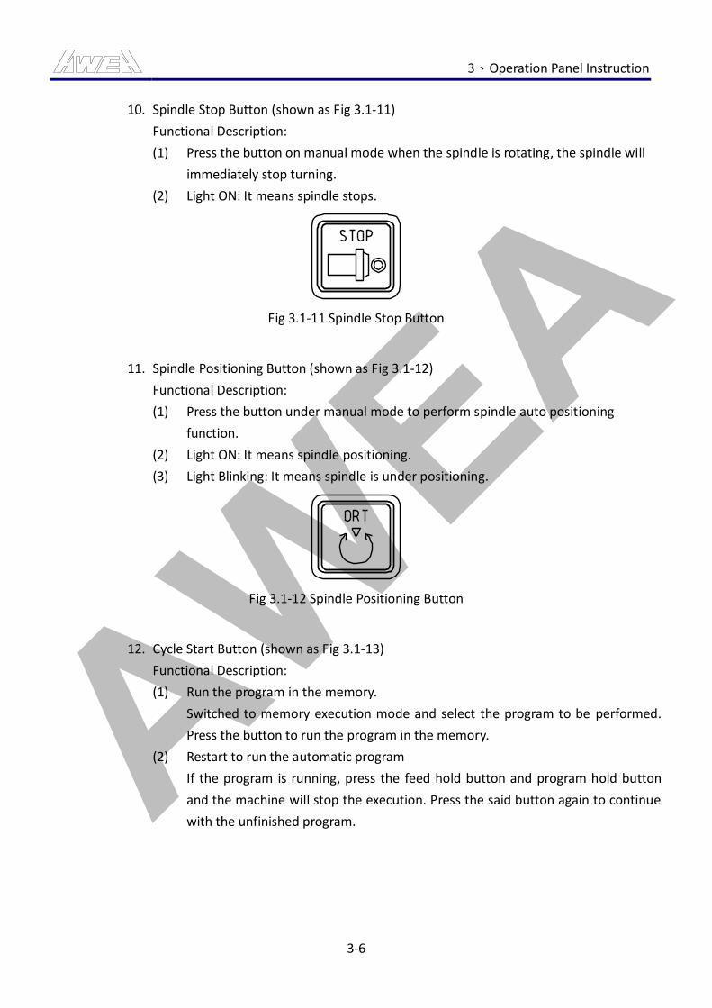
AWEA 3、Operation Panel Instruction
3-6
10. Spindle Stop Button (shown as Fig 3.1-11)
Functional Description:
(1) Press the button on manual mode when the spindle is rotating, the spindle will
immediately stop turning.
(2) Light ON: It means spindle stops.
Fig 3.1-11 Spindle Stop Button
11. Spindle Positioning Button (shown as Fig 3.1-12)
Functional Description:
(1) Press the button under manual mode to perform spindle auto positioning
function.
(2) Light ON: It means spindle positioning.
(3) Light Blinking: It means spindle is under positioning.
Fig 3.1-12 Spindle Positioning Button
12. Cycle Start Button (shown as Fig 3.1-13)
Functional Description:
(1) Run the program in the memory.
Switched to memory execution mode and select the program to be performed.
Press the button to run the program in the memory.
(2) Restart to run the automatic program
If the program is running, press the feed hold button and program hold button
and the machine will stop the execution. Press the said button again to continue
with the unfinished program.
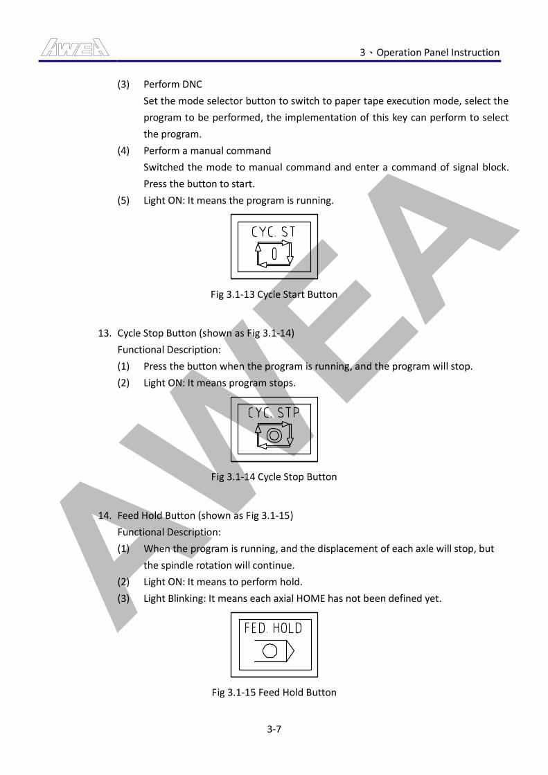
AWEA 3、Operation Panel Instruction
3-7
(3) Perform DNC
Set the mode selector button to switch to paper tape execution mode, select the
program to be performed, the implementation of this key can perform to select
the program.
(4) Perform a manual command
Switched the mode to manual command and enter a command of signal block.
Press the button to start.
(5) Light ON: It means the program is running.
Fig 3.1-13 Cycle Start Button
13. Cycle Stop Button (shown as Fig 3.1-14)
Functional Description:
(1) Press the button when the program is running, and the program will stop.
(2) Light ON: It means program stops.
Fig 3.1-14 Cycle Stop Button
14. Feed Hold Button (shown as Fig 3.1-15)
Functional Description:
(1) When the program is running, and the displacement of each axle will stop, but
the spindle rotation will continue.
(2) Light ON: It means to perform hold.
(3) Light Blinking: It means each axial HOME has not been defined yet.
Fig 3.1-15 Feed Hold Button
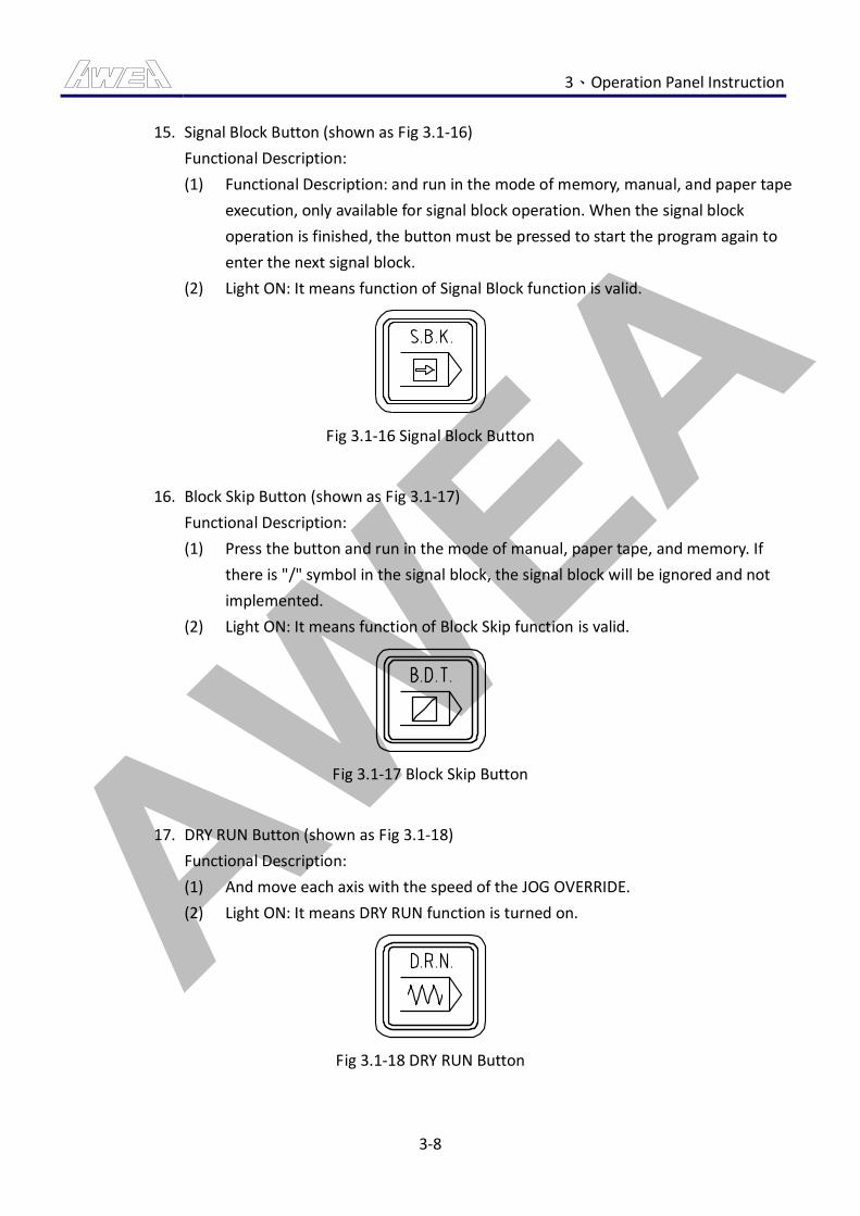
AWEA 3、Operation Panel Instruction
3-8
15. Signal Block Button (shown as Fig 3.1-16)
Functional Description:
(1) Functional Description: and run in the mode of memory, manual, and paper tape
execution, only available for signal block operation. When the signal block
operation is finished, the button must be pressed to start the program again to
enter the next signal block.
(2) Light ON: It means function of Signal Block function is valid.
Fig 3.1-16 Signal Block Button
16. Block Skip Button (shown as Fig 3.1-17)
Functional Description:
(1) Press the button and run in the mode of manual, paper tape, and memory. If
there is "/" symbol in the signal block, the signal block will be ignored and not
implemented.
(2) Light ON: It means function of Block Skip function is valid.
Fig 3.1-17 Block Skip Button
17. DRY RUN Button (shown as Fig 3.1-18)
Functional Description:
(1) And move each axis with the speed of the JOG OVERRIDE.
(2) Light ON: It means DRY RUN function is turned on.
Fig 3.1-18 DRY RUN Button
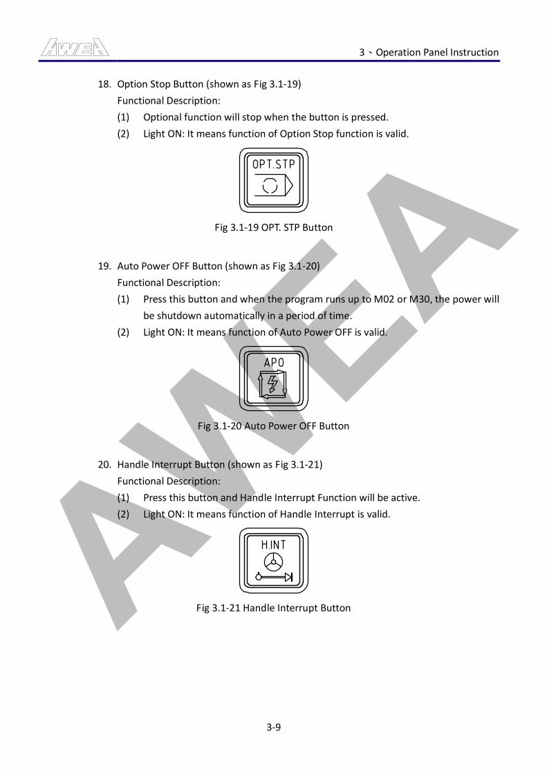
AWEA 3、Operation Panel Instruction
3-9
18. Option Stop Button (shown as Fig 3.1-19)
Functional Description:
(1) Optional function will stop when the button is pressed.
(2) Light ON: It means function of Option Stop function is valid.
Fig 3.1-19 OPT. STP Button
19. Auto Power OFF Button (shown as Fig 3.1-20)
Functional Description:
(1) Press this button and when the program runs up to M02 or M30, the power will
be shutdown automatically in a period of time.
(2) Light ON: It means function of Auto Power OFF is valid.
Fig 3.1-20 Auto Power OFF Button
20. Handle Interrupt Button (shown as Fig 3.1-21)
Functional Description:
(1) Press this button and Handle Interrupt Function will be active.
(2) Light ON: It means function of Handle Interrupt is valid.
Fig 3.1-21 Handle Interrupt Button
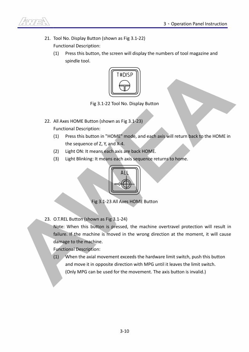
AWEA 3、Operation Panel Instruction
3-10
21. Tool No. Display Button (shown as Fig 3.1-22)
Functional Description:
(1) Press this button, the screen will display the numbers of tool magazine and
spindle tool.
Fig 3.1-22 Tool No. Display Button
22. All Axes HOME Button (shown as Fig 3.1-23)
Functional Description:
(1) Press this button in "HOME" mode, and each axis will return back to the HOME in
the sequence of Z, Y, and X-4.
(2) Light ON: It means each axis are back HOME.
(3) Light Blinking: It means each axis sequence returns to home.
Fig 3.1-23 All Axes HOME Button
23. O.T.REL Button (shown as Fig 3.1-24)
Note: When this button is pressed, the machine overtravel protection will result in
failure. If the machine is moved in the wrong direction at the moment, it will cause
damage to the machine.
Functional Description:
(1) When the axial movement exceeds the hardware limit switch, push this button
and move it in opposite direction with MPG until it leaves the limit switch.
(Only MPG can be used for the movement. The axis button is invalid.)
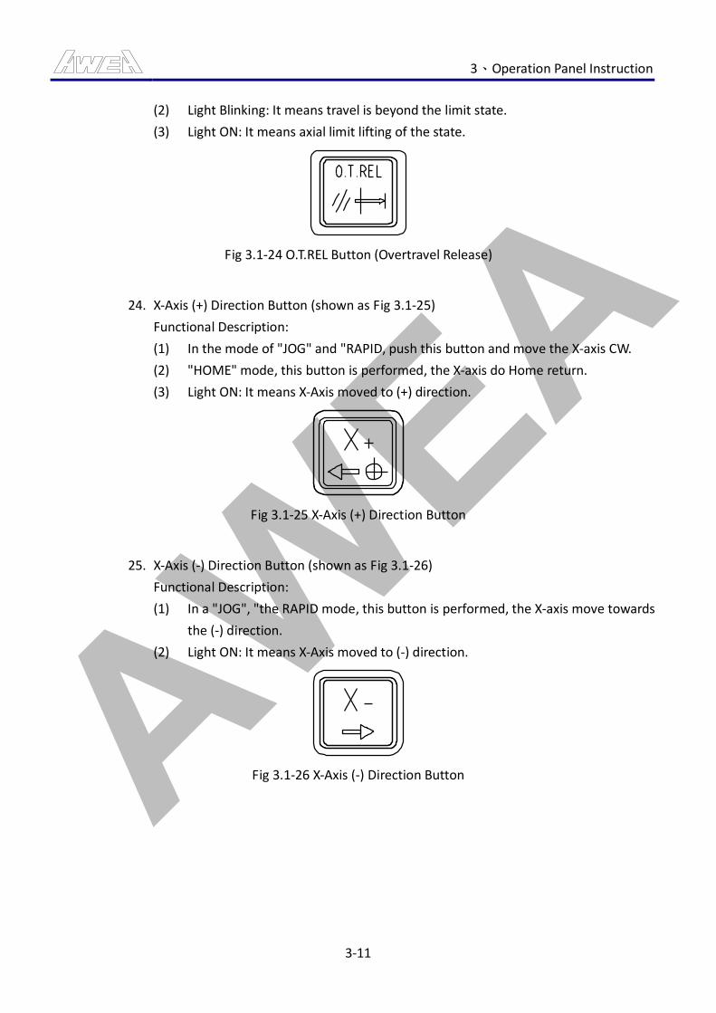
AWEA 3、Operation Panel Instruction
3-11
(2) Light Blinking: It means travel is beyond the limit state.
(3) Light ON: It means axial limit lifting of the state.
Fig 3.1-24 O.T.REL Button (Overtravel Release)
24. X-Axis (+) Direction Button (shown as Fig 3.1-25)
Functional Description:
(1) In the mode of "JOG" and "RAPID, push this button and move the X-axis CW.
(2) "HOME" mode, this button is performed, the X-axis do Home return.
(3) Light ON: It means X-Axis moved to (+) direction.
Fig 3.1-25 X-Axis (+) Direction Button
25. X-Axis (-) Direction Button (shown as Fig 3.1-26)
Functional Description:
(1) In a "JOG", "the RAPID mode, this button is performed, the X-axis move towards
the (-) direction.
(2) Light ON: It means X-Axis moved to (-) direction.
Fig 3.1-26 X-Axis (-) Direction Button
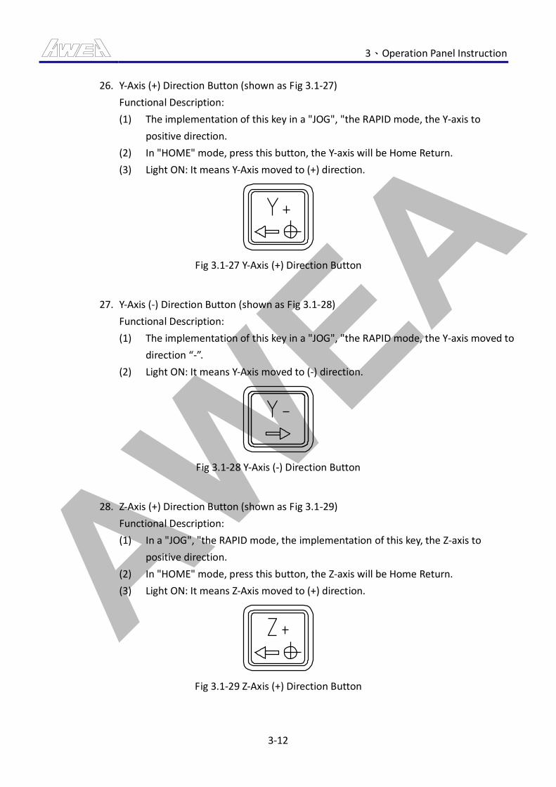
AWEA 3、Operation Panel Instruction
3-12
26. Y-Axis (+) Direction Button (shown as Fig 3.1-27)
Functional Description:
(1) The implementation of this key in a "JOG", "the RAPID mode, the Y-axis to
positive direction.
(2) In "HOME" mode, press this button, the Y-axis will be Home Return.
(3) Light ON: It means Y-Axis moved to (+) direction.
Fig 3.1-27 Y-Axis (+) Direction Button
27. Y-Axis (-) Direction Button (shown as Fig 3.1-28)
Functional Description:
(1) The implementation of this key in a "JOG", "the RAPID mode, the Y-axis moved to
direction “-”.
(2) Light ON: It means Y-Axis moved to (-) direction.
Fig 3.1-28 Y-Axis (-) Direction Button
28. Z-Axis (+) Direction Button (shown as Fig 3.1-29)
Functional Description:
(1) In a "JOG", "the RAPID mode, the implementation of this key, the Z-axis to
positive direction.
(2) In "HOME" mode, press this button, the Z-axis will be Home Return.
(3) Light ON: It means Z-Axis moved to (+) direction.
Fig 3.1-29 Z-Axis (+) Direction Button
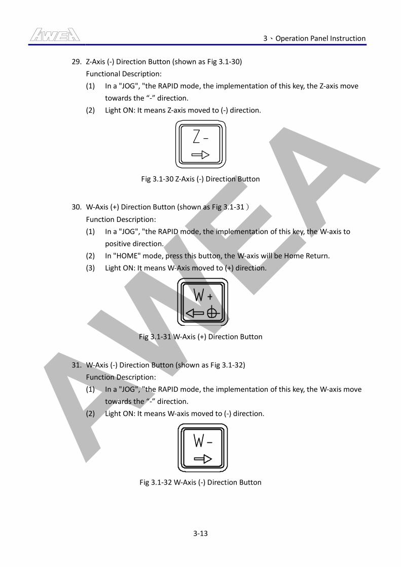
AWEA 3、Operation Panel Instruction
3-13
29. Z-Axis (-) Direction Button (shown as Fig 3.1-30)
Functional Description:
(1) In a "JOG", "the RAPID mode, the implementation of this key, the Z-axis move
towards the “-” direction.
(2) Light ON: It means Z-axis moved to (-) direction.
Fig 3.1-30 Z-Axis (-) Direction Button
30. W-Axis (+) Direction Button (shown as Fig 3.1-31)
Function Description:
(1) In a "JOG", "the RAPID mode, the implementation of this key, the W-axis to
positive direction.
(2) In "HOME" mode, press this button, the W-axis will be Home Return.
(3) Light ON: It means W-Axis moved to (+) direction.
Fig 3.1-31 W-Axis (+) Direction Button
31. W-Axis (-) Direction Button (shown as Fig 3.1-32)
Function Description:
(1) In a "JOG", "the RAPID mode, the implementation of this key, the W-axis move
towards the “-” direction.
(2) Light ON: It means W-axis moved to (-) direction.
Fig 3.1-32 W-Axis (-) Direction Button
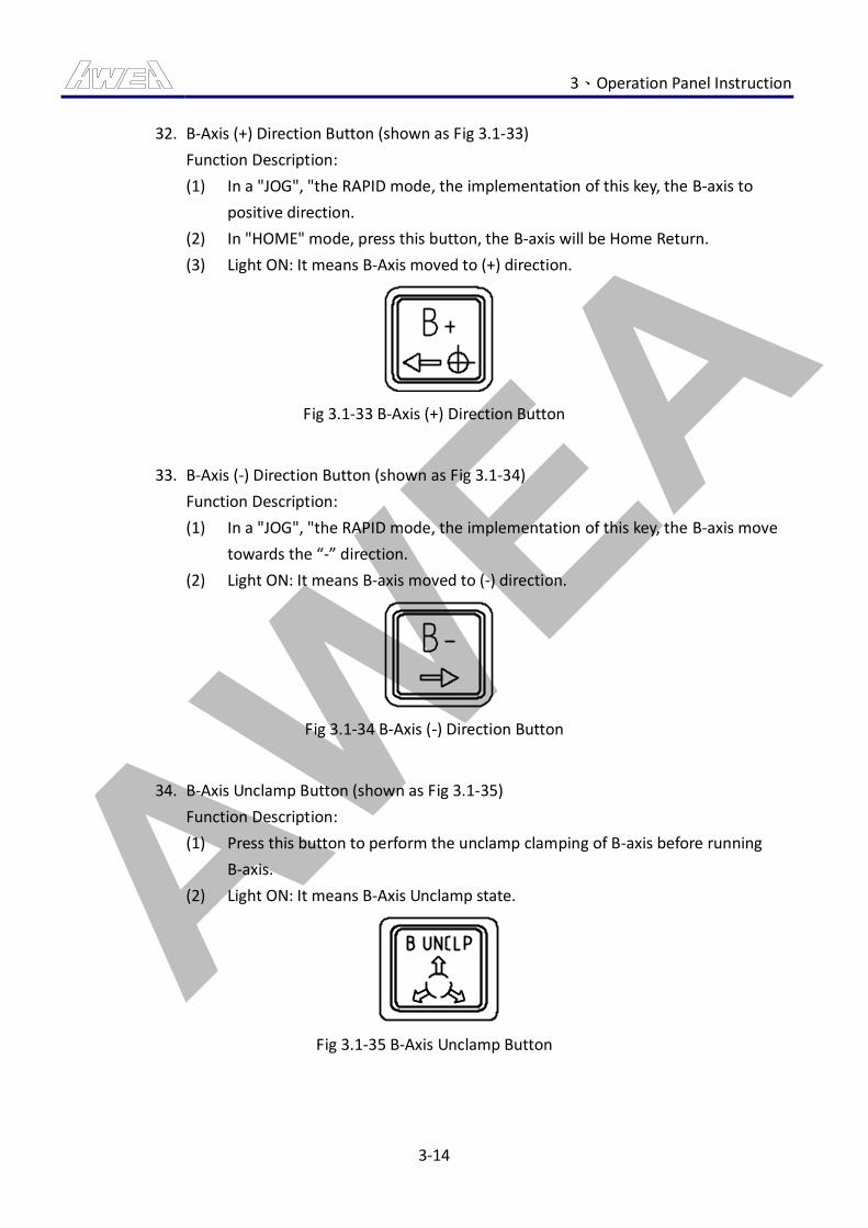
AWEA 3、Operation Panel Instruction
3-14
32. B-Axis (+) Direction Button (shown as Fig 3.1-33)
Function Description:
(1) In a "JOG", "the RAPID mode, the implementation of this key, the B-axis to
positive direction.
(2) In "HOME" mode, press this button, the B-axis will be Home Return.
(3) Light ON: It means B-Axis moved to (+) direction.
Fig 3.1-33 B-Axis (+) Direction Button
33. B-Axis (-) Direction Button (shown as Fig 3.1-34)
Function Description:
(1) In a "JOG", "the RAPID mode, the implementation of this key, the B-axis move
towards the “-” direction.
(2) Light ON: It means B-axis moved to (-) direction.
Fig 3.1-34 B-Axis (-) Direction Button
34. B-Axis Unclamp Button (shown as Fig 3.1-35)
Function Description:
(1) Press this button to perform the unclamp clamping of B-axis before running
B-axis.
(2) Light ON: It means B-Axis Unclamp state.
Fig 3.1-35 B-Axis Unclamp Button
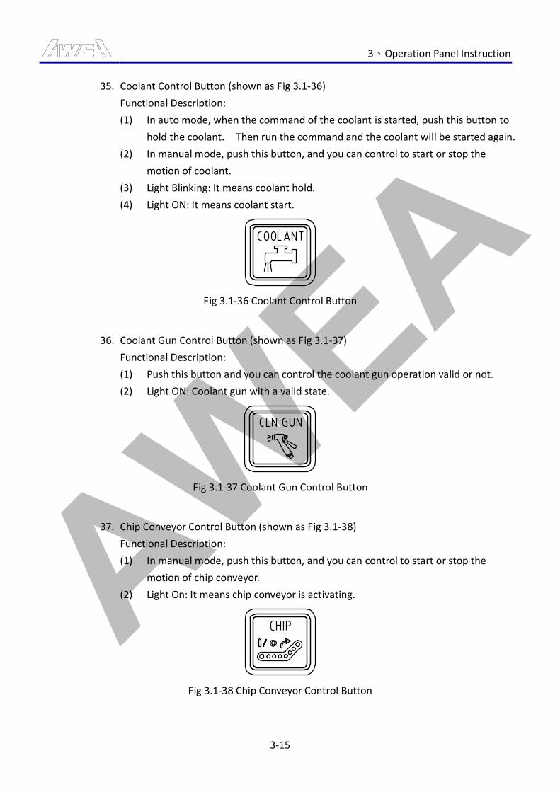
AWEA 3、Operation Panel Instruction
3-15
35. Coolant Control Button (shown as Fig 3.1-36)
Functional Description:
(1) In auto mode, when the command of the coolant is started, push this button to
hold the coolant. Then run the command and the coolant will be started again.
(2) In manual mode, push this button, and you can control to start or stop the
motion of coolant.
(3) Light Blinking: It means coolant hold.
(4) Light ON: It means coolant start.
Fig 3.1-36 Coolant Control Button
36. Coolant Gun Control Button (shown as Fig 3.1-37)
Functional Description:
(1) Push this button and you can control the coolant gun operation valid or not.
(2) Light ON: Coolant gun with a valid state.
Fig 3.1-37 Coolant Gun Control Button
37. Chip Conveyor Control Button (shown as Fig 3.1-38)
Functional Description:
(1) In manual mode, push this button, and you can control to start or stop the
motion of chip conveyor.
(2) Light On: It means chip conveyor is activating.
Fig 3.1-38 Chip Conveyor Control Button
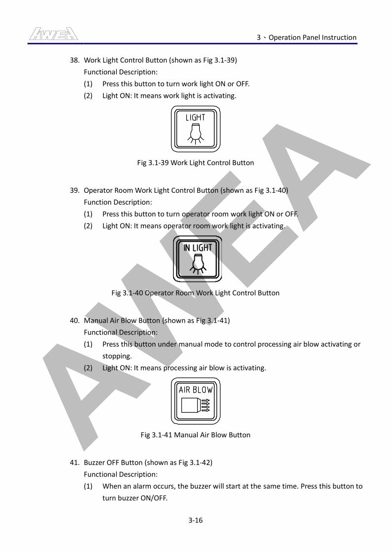
AWEA 3、Operation Panel Instruction
3-16
38. Work Light Control Button (shown as Fig 3.1-39)
Functional Description:
(1) Press this button to turn work light ON or OFF.
(2) Light ON: It means work light is activating.
Fig 3.1-39 Work Light Control Button
39. Operator Room Work Light Control Button (shown as Fig 3.1-40)
Function Description:
(1) Press this button to turn operator room work light ON or OFF.
(2) Light ON: It means operator room work light is activating.
Fig 3.1-40 Operator Room Work Light Control Button
40. Manual Air Blow Button (shown as Fig 3.1-41)
Functional Description:
(1) Press this button under manual mode to control processing air blow activating or
stopping.
(2) Light ON: It means processing air blow is activating.
Fig 3.1-41 Manual Air Blow Button
41. Buzzer OFF Button (shown as Fig 3.1-42)
Functional Description:
(1) When an alarm occurs, the buzzer will start at the same time. Press this button to
turn buzzer ON/OFF.
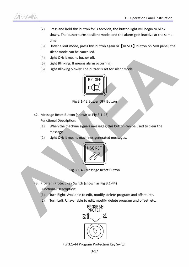
AWEA 3、Operation Panel Instruction
3-17
(2) Press and hold this button for 3 seconds, the button light will begin to blink
slowly. The buzzer turns to silent mode, and the alarm gets inactive at the same
time.
(3) Under silent mode, press this button again or 【RESET】 button on MDI panel, the
silent mode can be cancelled.
(4) Light ON: It means buzzer off.
(5) Light Blinking: It means alarm occurring.
(6) Light Blinking Slowly: The buzzer is set for silent mode.
Fig 3.1-42 Buzzer OFF Button
42. Message Reset Button (shown as Fig 3.1-43)
Functional Description:
(1) When the machine signals messages, this button can be used to clear the
message.
(2) Light ON: It means machines generated messages.
Fig 3.1-43 Message Reset Button
43. Program Protect Key Switch (shown as Fig 3.1-44)
Functional Description:
(1) Turn Right: Available to edit, modify, delete program and offset, etc.
(2) Turn Left: Unavailable to edit, modify, delete program and offset, etc.
Fig 3.1-44 Program Protection Key Switch
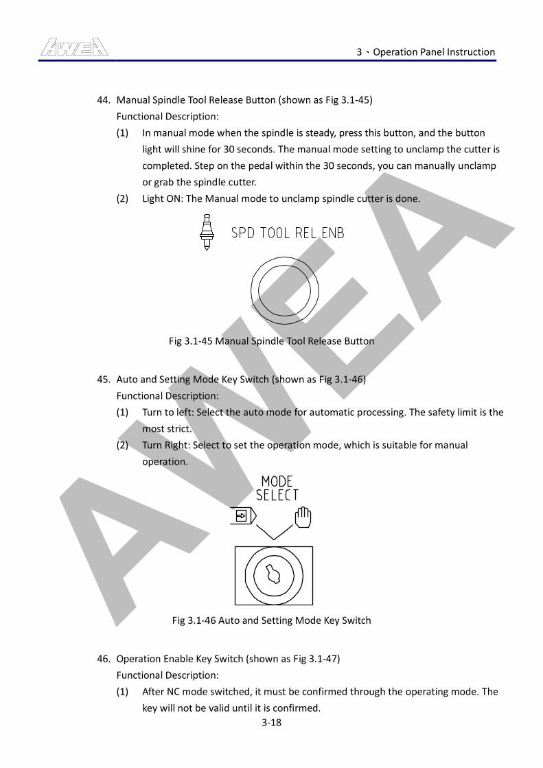
AWEA 3、Operation Panel Instruction
3-18
44. Manual Spindle Tool Release Button (shown as Fig 3.1-45)
Functional Description:
(1) In manual mode when the spindle is steady, press this button, and the button
light will shine for 30 seconds. The manual mode setting to unclamp the cutter is
completed. Step on the pedal within the 30 seconds, you can manually unclamp
or grab the spindle cutter.
(2) Light ON: The Manual mode to unclamp spindle cutter is done.
Fig 3.1-45 Manual Spindle Tool Release Button
45. Auto and Setting Mode Key Switch (shown as Fig 3.1-46)
Functional Description:
(1) Turn to left: Select the auto mode for automatic processing. The safety limit is the
most strict.
(2) Turn Right: Select to set the operation mode, which is suitable for manual
operation.
Fig 3.1-46 Auto and Setting Mode Key Switch
46. Operation Enable Key Switch (shown as Fig 3.1-47)
Functional Description:
(1) After NC mode switched, it must be confirmed through the operating mode. The
key will not be valid until it is confirmed.
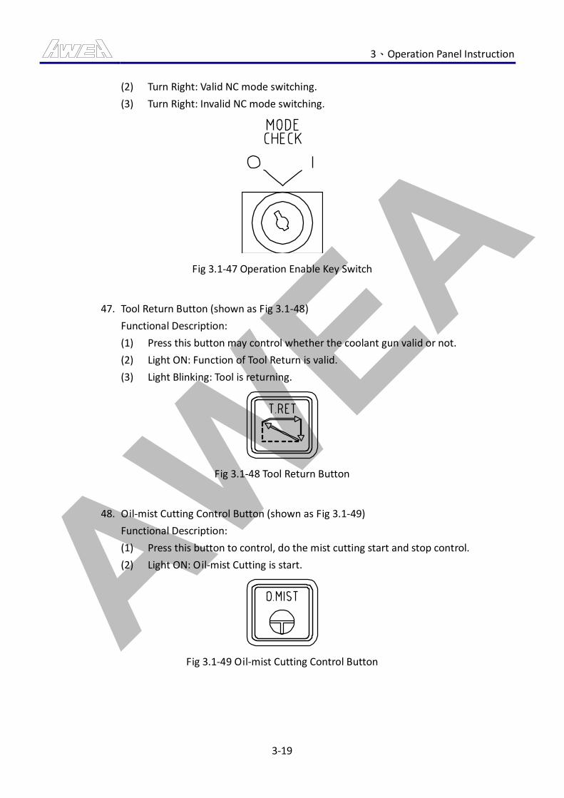
AWEA 3、Operation Panel Instruction
3-19
(2) Turn Right: Valid NC mode switching.
(3) Turn Right: Invalid NC mode switching.
Fig 3.1-47 Operation Enable Key Switch
47. Tool Return Button (shown as Fig 3.1-48)
Functional Description:
(1) Press this button may control whether the coolant gun valid or not.
(2) Light ON: Function of Tool Return is valid.
(3) Light Blinking: Tool is returning.
Fig 3.1-48 Tool Return Button
48. Oil-mist Cutting Control Button (shown as Fig 3.1-49)
Functional Description:
(1) Press this button to control, do the mist cutting start and stop control.
(2) Light ON: Oil-mist Cutting is start.
Fig 3.1-49 Oil-mist Cutting Control Button
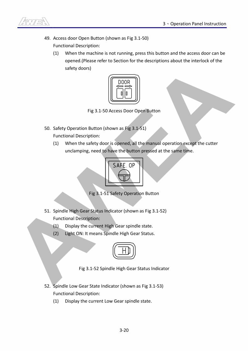
AWEA 3、Operation Panel Instruction
3-20
49. Access door Open Button (shown as Fig 3.1-50)
Functional Description:
(1) When the machine is not running, press this button and the access door can be
opened.(Please refer to Section for the descriptions about the interlock of the
safety doors)
Fig 3.1-50 Access Door Open Button
50. Safety Operation Button (shown as Fig 3.1-51)
Functional Description:
(1) When the safety door is opened, all the manual operation except the cutter
unclamping, need to have the button pressed at the same time.
Fig 3.1-51 Safety Operation Button
51. Spindle High Gear Status Indicator (shown as Fig 3.1-52)
Functional Description:
(1) Display the current High Gear spindle state.
(2) Light ON: It means Spindle High Gear Status.
Fig 3.1-52 Spindle High Gear Status Indicator
52. Spindle Low Gear State Indicator (shown as Fig 3.1-53)
Functional Description:
(1) Display the current Low Gear spindle state.
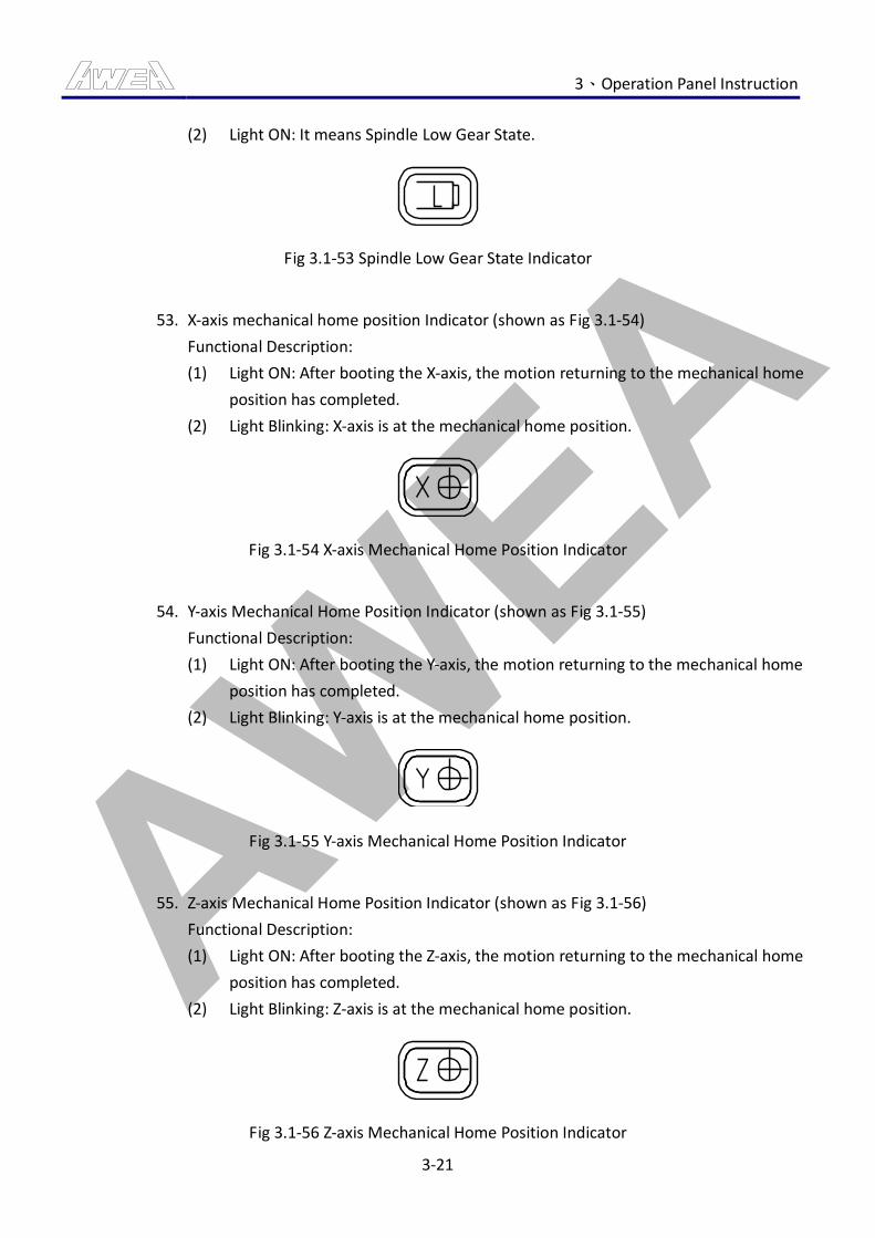
AWEA 3、Operation Panel Instruction
3-21
(2) Light ON: It means Spindle Low Gear State.
Fig 3.1-53 Spindle Low Gear State Indicator
53. X-axis mechanical home position Indicator (shown as Fig 3.1-54)
Functional Description:
(1) Light ON: After booting the X-axis, the motion returning to the mechanical home
position has completed.
(2) Light Blinking: X-axis is at the mechanical home position.
Fig 3.1-54 X-axis Mechanical Home Position Indicator
54. Y-axis Mechanical Home Position Indicator (shown as Fig 3.1-55)
Functional Description:
(1) Light ON: After booting the Y-axis, the motion returning to the mechanical home
position has completed.
(2) Light Blinking: Y-axis is at the mechanical home position.
Fig 3.1-55 Y-axis Mechanical Home Position Indicator
55. Z-axis Mechanical Home Position Indicator (shown as Fig 3.1-56)
Functional Description:
(1) Light ON: After booting the Z-axis, the motion returning to the mechanical home
position has completed.
(2) Light Blinking: Z-axis is at the mechanical home position.
Fig 3.1-56 Z-axis Mechanical Home Position Indicator
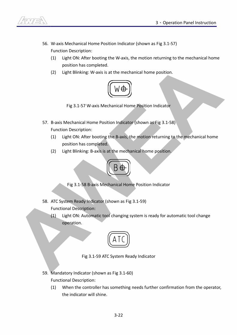
AWEA 3、Operation Panel Instruction
3-22
56. W-axis Mechanical Home Position Indicator (shown as Fig 3.1-57)
Function Description:
(1) Light ON: After booting the W-axis, the motion returning to the mechanical home
position has completed.
(2) Light Blinking: W-axis is at the mechanical home position.
Fig 3.1-57 W-axis Mechanical Home Position Indicator
57. B-axis Mechanical Home Position Indicator (shown as Fig 3.1-58)
Function Description:
(1) Light ON: After booting the B-axis, the motion returning to the mechanical home
position has completed.
(2) Light Blinking: B-axis is at the mechanical home position.
Fig 3.1-58 B-axis Mechanical Home Position Indicator
58. ATC System Ready Indicator (shown as Fig 3.1-59)
Functional Description:
(1) Light ON: Automatic tool changing system is ready for automatic tool change
operation.
Fig 3.1-59 ATC System Ready Indicator
59. Mandatory Indicator (shown as Fig 3.1-60)
Functional Description:
(1) When the controller has something needs further confirmation from the operator,
the indicator will shine.
AWEA 3、Operation Panel Instruction
3-23
(2) Light ON: Enter enforce condition, the operator needs to confirm the further
motions.
Fig 3.1-60 Mandatory Indicator
60. Message Indicator (shown as Fig 3.1-61)
Functional Description:
(1) When the machine signals messages, it can inform operator to perform
continuous checking action.
(2) Light ON: It means machine is signaling messages.
Fig 3.1-61 Message Indicator
61. Warning Indicator (shown as Fig 3.1-62)
Functional Description:
(1) When alarm occurs in machine, it can inform operator to perform continuous
checking action.
(2) Light ON: It means so far the machine is signaling alarm.
Fig 3.1-62 Alarm Indicator
62. Emergency Stop Indicator (shown as Fig 3.1-63)
Functional Description:
(1) When alarm occurs in machine, it can inform operator to perform continuous
checking action.

AWEA 3、Operation Panel Instruction
3-24
(2) Light ON: Emergency stop status.
Fig 3.1-63 Emergency Stop Indicator
63. Spindle load meter (shown as Fig 3.1-64)
Functional Description:
(1) Spindle load at the moment.
Fig 3.1-64 Spindle load meter
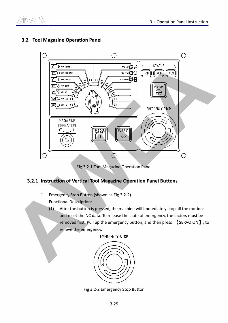
AWEA 3、Operation Panel Instruction
3-25
3.2 Tool Magazine Operation Panel
Fig 3.2-1 Tool Magazine Operation Panel
3.2.1 Instruction of Vertical Tool Magazine Operation Panel Buttons
1. Emergency Stop Button (shown as Fig 3.2-2)
Functional Description:
(1) After the button is pressed, the machine will immediately stop all the motions
and reset the NC data. To release the state of emergency, the factors must be
removed first. Pull up the emergency button, and then press 【SERVO ON】, to
relieve the emergency.
Fig 3.2-2 Emergency Stop Button
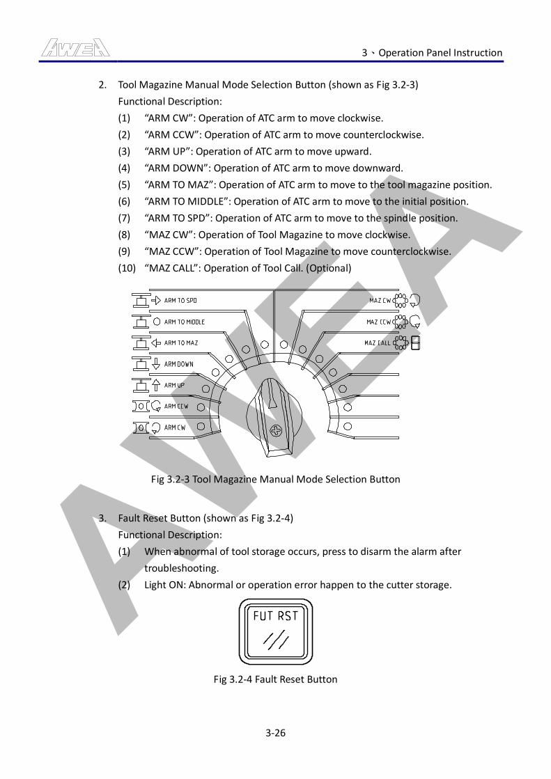
AWEA 3、Operation Panel Instruction
3-26
2. Tool Magazine Manual Mode Selection Button (shown as Fig 3.2-3)
Functional Description:
(1) “ARM CW”: Operation of ATC arm to move clockwise.
(2) “ARM CCW”: Operation of ATC arm to move counterclockwise.
(3) “ARM UP”: Operation of ATC arm to move upward.
(4) “ARM DOWN”: Operation of ATC arm to move downward.
(5) “ARM TO MAZ”: Operation of ATC arm to move to the tool magazine position.
(6) “ARM TO MIDDLE”: Operation of ATC arm to move to the initial position.
(7) “ARM TO SPD”: Operation of ATC arm to move to the spindle position.
(8) “MAZ CW”: Operation of Tool Magazine to move clockwise.
(9) “MAZ CCW”: Operation of Tool Magazine to move counterclockwise.
(10) “MAZ CALL”: Operation of Tool Call. (Optional)
Fig 3.2-3 Tool Magazine Manual Mode Selection Button
3. Fault Reset Button (shown as Fig 3.2-4)
Functional Description:
(1) When abnormal of tool storage occurs, press to disarm the alarm after
troubleshooting.
(2) Light ON: Abnormal or operation error happen to the cutter storage.
Fig 3.2-4 Fault Reset Button
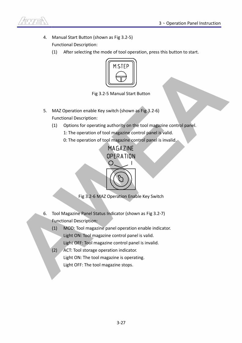
AWEA 3、Operation Panel Instruction
3-27
4. Manual Start Button (shown as Fig 3.2-5)
Functional Description:
(1) After selecting the mode of tool operation, press this button to start.
Fig 3.2-5 Manual Start Button
5. MAZ Operation enable Key switch (shown as Fig 3.2-6)
Functional Description:
(1) Options for operating authority on the tool magazine control panel.
1: The operation of tool magazine control panel is valid.
0: The operation of tool magazine control panel is invalid.
Fig 3.2-6 MAZ Operation Enable Key Switch
6. Tool Magazine Panel Status Indicator (shown as Fig 3.2-7)
Functional Description:
(1) MOD: Tool magazine panel operation enable indicator.
Light ON: Tool magazine control panel is valid.
Light OFF: Tool magazine control panel is invalid.
(2) ACT: Tool storage operation indicator.
Light ON: The tool magazine is operating.
Light OFF: The tool magazine stops.
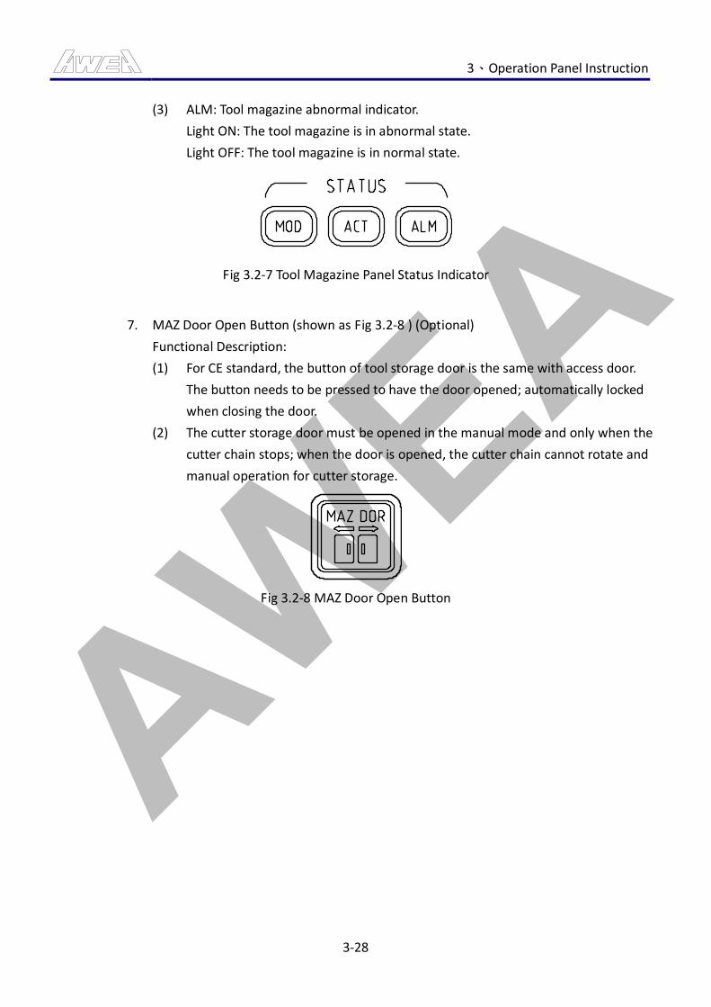
AWEA 3、Operation Panel Instruction
3-28
(3) ALM: Tool magazine abnormal indicator.
Light ON: The tool magazine is in abnormal state.
Light OFF: The tool magazine is in normal state.
Fig 3.2-7 Tool Magazine Panel Status Indicator
7. MAZ Door Open Button (shown as Fig 3.2-8 ) (Optional)
Functional Description:
(1) For CE standard, the button of tool storage door is the same with access door.
The button needs to be pressed to have the door opened; automatically locked
when closing the door.
(2) The cutter storage door must be opened in the manual mode and only when the
cutter chain stops; when the door is opened, the cutter chain cannot rotate and
manual operation for cutter storage.
Fig 3.2-8 MAZ Door Open Button
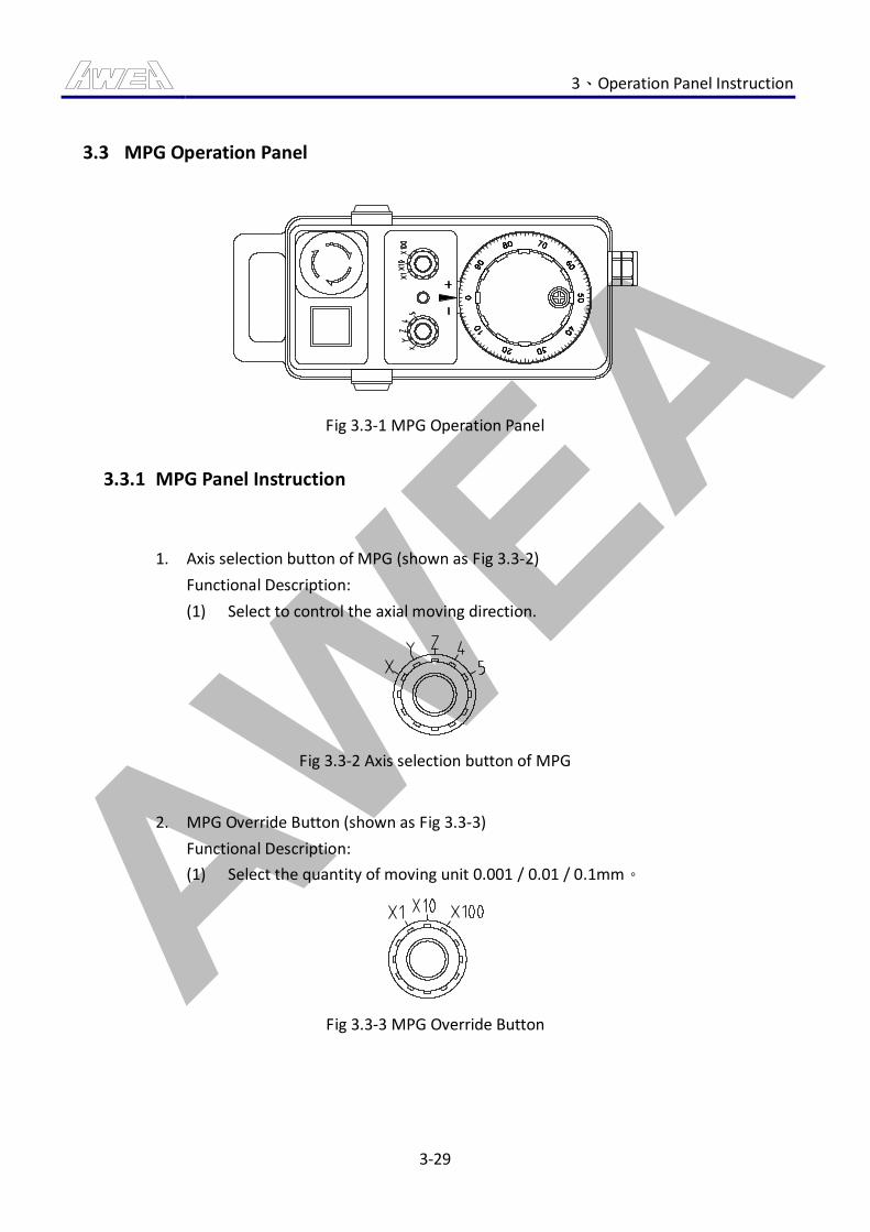
AWEA 3、Operation Panel Instruction
3-29
3.3 MPG Operation Panel
Fig 3.3-1 MPG Operation Panel
3.3.1 MPG Panel Instruction
1. Axis selection button of MPG (shown as Fig 3.3-2)
Functional Description:
(1) Select to control the axial moving direction.
Fig 3.3-2 Axis selection button of MPG
2. MPG Override Button (shown as Fig 3.3-3)
Functional Description:
(1) Select the quantity of moving unit 0.001 / 0.01 / 0.1mm。
Fig 3.3-3 MPG Override Button
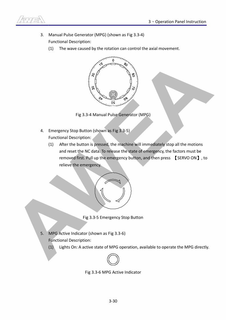
AWEA 3、Operation Panel Instruction
3-30
3. Manual Pulse Generator (MPG) (shown as Fig 3.3-4)
Functional Description:
(1) The wave caused by the rotation can control the axial movement.
Fig 3.3-4 Manual Pulse Generator (MPG)
4. Emergency Stop Button (shown as Fig 3.3-5)
Functional Description:
(1) After the button is pressed, the machine will immediately stop all the motions
and reset the NC data. To release the state of emergency, the factors must be
removed first. Pull up the emergency button, and then press 【SERVO ON】, to
relieve the emergency.
Fig 3.3-5 Emergency Stop Button
5. MPG Active Indicator (shown as Fig 3.3-6)
Functional Description:
(1) Lights On: A active state of MPG operation, available to operate the MPG directly.
Fig 3.3-6 MPG Active Indicator
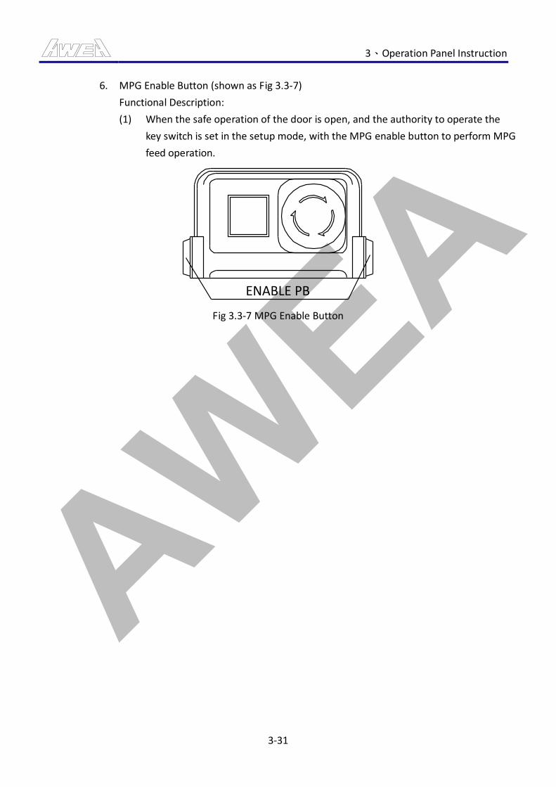
AWEA 3、Operation Panel Instruction
3-31
6. MPG Enable Button (shown as Fig 3.3-7)
Functional Description:
(1) When the safe operation of the door is open, and the authority to operate the
key switch is set in the setup mode, with the MPG enable button to perform MPG
feed operation.
ENABLE PB
Fig 3.3-7 MPG Enable Button
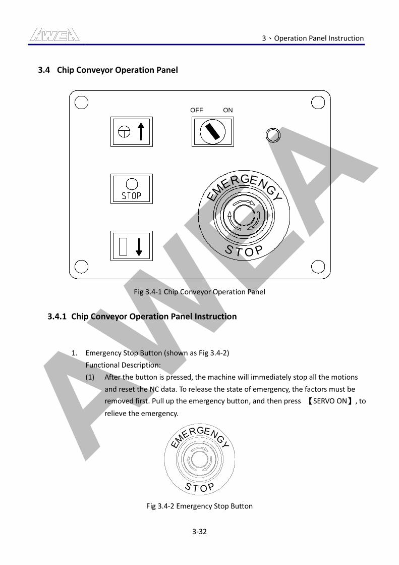
AWEA 3、Operation Panel Instruction
3-32
3.4 Chip Conveyor Operation Panel
POTS
Y
GNEGREM
E
OFF ON
Fig 3.4-1 Chip Conveyor Operation Panel
3.4.1 Chip Conveyor Operation Panel Instruction
1. Emergency Stop Button (shown as Fig 3.4-2)
Functional Description:
(1) After the button is pressed, the machine will immediately stop all the motions
and reset the NC data. To release the state of emergency, the factors must be
removed first. Pull up the emergency button, and then press 【SERVO ON】, to
relieve the emergency.
POTS
Y
GNEGREM
E
Fig 3.4-2 Emergency Stop Button
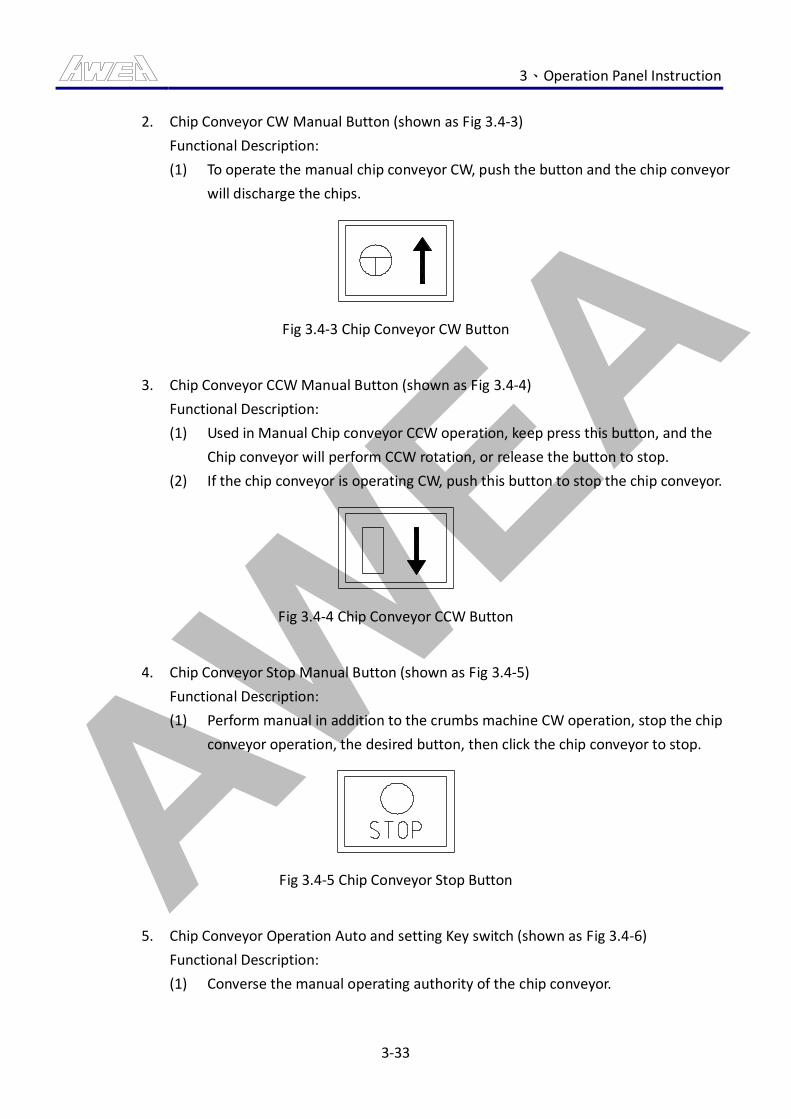
AWEA 3、Operation Panel Instruction
3-33
2. Chip Conveyor CW Manual Button (shown as Fig 3.4-3)
Functional Description:
(1) To operate the manual chip conveyor CW, push the button and the chip conveyor
will discharge the chips.
Fig 3.4-3 Chip Conveyor CW Button
3. Chip Conveyor CCW Manual Button (shown as Fig 3.4-4)
Functional Description:
(1) Used in Manual Chip conveyor CCW operation, keep press this button, and the
Chip conveyor will perform CCW rotation, or release the button to stop.
(2) If the chip conveyor is operating CW, push this button to stop the chip conveyor.
Fig 3.4-4 Chip Conveyor CCW Button
4. Chip Conveyor Stop Manual Button (shown as Fig 3.4-5)
Functional Description:
(1) Perform manual in addition to the crumbs machine CW operation, stop the chip
conveyor operation, the desired button, then click the chip conveyor to stop.
Fig 3.4-5 Chip Conveyor Stop Button
5. Chip Conveyor Operation Auto and setting Key switch (shown as Fig 3.4-6)
Functional Description:
(1) Converse the manual operating authority of the chip conveyor.
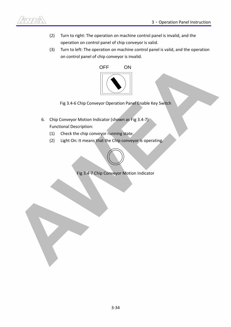
AWEA 3、Operation Panel Instruction
3-34
(2) Turn to right: The operation on machine control panel is invalid, and the
operation on control panel of chip conveyor is valid.
(3) Turn to left: The operation on machine control panel is valid, and the operation
on control panel of chip conveyor is invalid.
OFF ON
Fig 3.4-6 Chip Conveyor Operation Panel Enable Key Switch
6. Chip Conveyor Motion Indicator (shown as Fig 3.4-7)
Functional Description:
(1) Check the chip conveyor running state.
(2) Light On: It means that the Chip conveyor is operating.
Fig 3.4-7 Chip Conveyor Motion Indicator
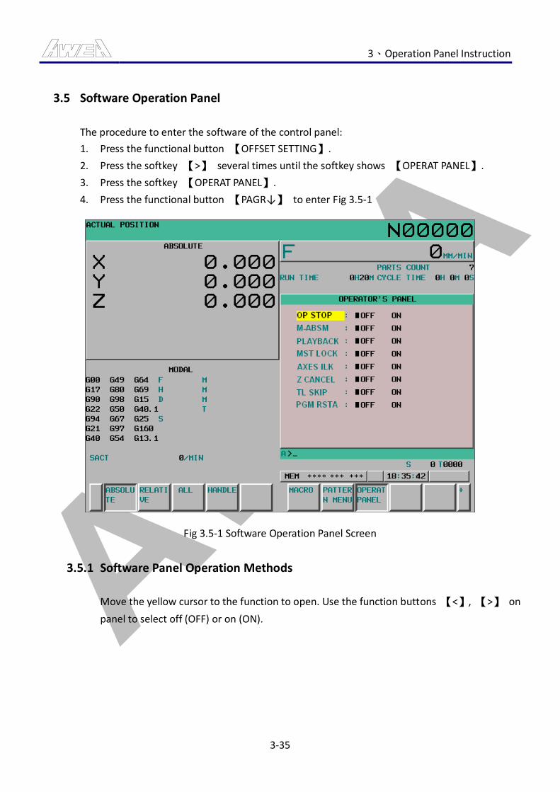
AWEA 3、Operation Panel Instruction
3-35
3.5 Software Operation Panel
The procedure to enter the software of the control panel:
1. Press the functional button 【OFFSET SETTING】.
2. Press the softkey 【>】 several times until the softkey shows 【OPERAT PANEL】.
3. Press the softkey 【OPERAT PANEL】.
4. Press the functional button 【PAGR↓】 to enter Fig 3.5-1
Fig 3.5-1 Software Operation Panel Screen
3.5.1 Software Panel Operation Methods
Move the yellow cursor to the function to open. Use the function buttons 【<】, 【>】 on
panel to select off (OFF) or on (ON).
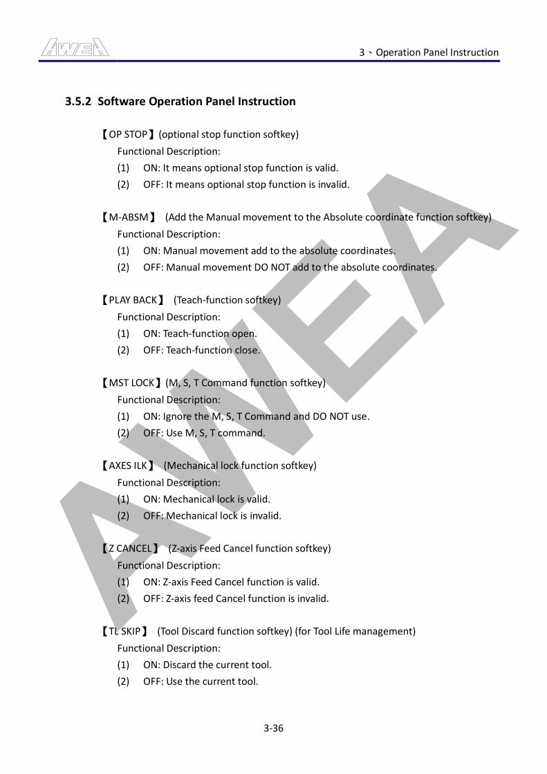
AWEA 3、Operation Panel Instruction
3-36
3.5.2 Software Operation Panel Instruction
【OP STOP】(optional stop function softkey)
Functional Description:
(1) ON: It means optional stop function is valid.
(2) OFF: It means optional stop function is invalid.
【M-ABSM】 (Add the Manual movement to the Absolute coordinate function softkey)
Functional Description:
(1) ON: Manual movement add to the absolute coordinates.
(2) OFF: Manual movement DO NOT add to the absolute coordinates.
【PLAY BACK】 (Teach-function softkey)
Functional Description:
(1) ON: Teach-function open.
(2) OFF: Teach-function close.
【MST LOCK】(M, S, T Command function softkey)
Functional Description:
(1) ON: Ignore the M, S, T Command and DO NOT use.
(2) OFF: Use M, S, T command.
【AXES ILK】 (Mechanical lock function softkey)
Functional Description:
(1) ON: Mechanical lock is valid.
(2) OFF: Mechanical lock is invalid.
【Z CANCEL】 (Z-axis Feed Cancel function softkey)
Functional Description:
(1) ON: Z-axis Feed Cancel function is valid.
(2) OFF: Z-axis feed Cancel function is invalid.
【TL SKIP】 (Tool Discard function softkey) (for Tool Life management)
Functional Description:
(1) ON: Discard the current tool.
(2) OFF: Use the current tool.
AWEA 3、Operation Panel Instruction
3-37
【PGM RSTA】(Program Restart function softkey)
Functional Description:
(1) ON: Program Restart function is valid.
(2) OFF: Program Restart is invalid.
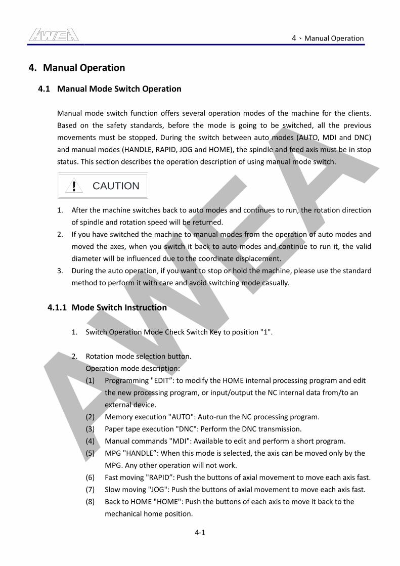
AWEA 4、Manual Operation
4-1
4. Manual Operation
4.1 Manual Mode Switch Operation
Manual mode switch function offers several operation modes of the machine for the clients.
Based on the safety standards, before the mode is going to be switched, all the previous
movements must be stopped. During the switch between auto modes (AUTO, MDI and DNC)
and manual modes (HANDLE, RAPID, JOG and HOME), the spindle and feed axis must be in stop
status. This section describes the operation description of using manual mode switch.
CAUTION
1. After the machine switches back to auto modes and continues to run, the rotation direction
of spindle and rotation speed will be returned.
2. If you have switched the machine to manual modes from the operation of auto modes and
moved the axes, when you switch it back to auto modes and continue to run it, the valid
diameter will be influenced due to the coordinate displacement.
3. During the auto operation, if you want to stop or hold the machine, please use the standard
method to perform it with care and avoid switching mode casually.
4.1.1 Mode Switch Instruction
1. Switch Operation Mode Check Switch Key to position "1".
2. Rotation mode selection button.
Operation mode description:
(1) Programming "EDIT”: to modify the HOME internal processing program and edit
the new processing program, or input/output the NC internal data from/to an
external device.
(2) Memory execution "AUTO": Auto-run the NC processing program.
(3) Paper tape execution "DNC": Perform the DNC transmission.
(4) Manual commands "MDI": Available to edit and perform a short program.
(5) MPG "HANDLE”: When this mode is selected, the axis can be moved only by the
MPG. Any other operation will not work.
(6) Fast moving "RAPID”: Push the buttons of axial movement to move each axis fast.
(7) Slow moving "JOG": Push the buttons of axial movement to move each axis fast.
(8) Back to HOME "HOME": Push the buttons of each axis to move it back to the
mechanical home position.
AWEA 4、Manual Operation
4-2
3. Complete the Mode Switch Operation.
Remark:
During the operation of auto modes, please make sure that the key is switched to
position “0” and pulled out to prevent the happening of abnormalities like machine
shutdown and damage to workpiece owing to accidental mode switch done by others.
AWEA 4、Manual Operation
4-3
4.2 Manual HOME Operation
Manual home return function is for increment decoder. Because the increment decoder can not
save the current coordinates, therefore, when the machine is started each time, all the axes
need to return their Home positions. This section describes the operation description of manual
home return.
CAUTION
1. If the axis is on the HOME or LIMIT DOG, then the home return can not be performed.
Therefore, before the execution of home return, please use the “HANDLE” mode to move
every axis 200 mm away from its own HOME.
2. Before the three axes return to their Home positions, the heads must be in clamping state.
3. If 4th-axis, rotary console, is purchased, you need to have the z-axis returned to its HOME
first before executing home return for the other axes to prevent the damage to the rotary
console.
4. Before performing the axial move, make sure that there is no staff inside of or around the
machine, and then can it be performed.
5. Before performing the axial move, make sure that the access door is closed, and then can it
be performed.
DANGER
1. DO NOT get close to the table to avoid danger while it is moving.
4.2.1 Instruction for Single Axis HOME Operation
1. Switch the rotation mode to "HOME" mode.
2. Executing the button “AXIS POSITIVE” forces the target axis to move toward the
mechanical home position. Before the axis arrives the mechanical home position, the
indicator light of the button will be on (constantly).After the axis arrives the HOME, the
indicator light of the button turns off. At the time, the mechanical coordinate of the
target axis is 0.
Remark:
(1) During the process, if the button 【RESET】 on the MDI board is pressed or the
machine mode is switched away from “HOME”, then the home return to
mechanical home position will be halted.
AWEA 4、Manual Operation
4-4
3. During the process of home return, the axes move to deceleration position with rapid
feed rate first and then move to the HOME with the speed of 200 mm/min. You can use
the rapid 【FEEDRATE OVERRIDE BUTTON】 to adjust the speed of rapid movement.
4. When the axis is on the HOME, the indicator light of axis HOME is in flickering state.
Remark:
(1) If the first axis home return is completed after the machine starts, the indicator
light of axis HOME will keep turned on. It means that the home return is
completed.
5. Completed Single Axis HOME manual operation.
4.2.2 Instruction for All Axes HOME Operation
1. Switch the rotation mode to "HOME" mode.
2. Press the button “ALL AXES HOME”.
After the button is pressed, the Z-axis returns its HOME first. The Z-axis should return
its HOME before the X, Y and forth axes start to return their Home positions.
3. During the process of home return, the indicator light of this button flickers. After every
axis is on its mechanical home position, the indicator light of this button will be on
(constantly).
4. During the process of home return, the axes move to deceleration position with rapid
feed rate first and then move to the HOME with the speed of 200 mm/min. You can use
the rapid 【FEEDRATE OVERRIDE BUTTON】 to adjust the speed of rapid movement.
Remark:
(1) During the process, if the button 【RESET】 on the MDI board is pressed or the
machine mode is switched away from “HOME”, then the home return to
mechanical home position will be halted.
5. When the axis is on the HOME, the indicator light of axis HOME is in flickering state.
Remark:
(1) If the first axis home return is completed after the machine starts, the indicator
light of axis HOME will keep turned on. It means that the home return is
completed.
6. Completed All Axes HOME manual operation.
AWEA 4、Manual Operation
4-5
4.3 Manual Slow Feed Operation
Manual JOG feed function is for simple valid. Because simple valid only needs a single direction
movement of axis, therefore, it only needs to work with the spindle rotation feed rate to finish
the job. This section describes the operation description of manual JOG feed.
CAUTION
1. When the heads are in unclamp state, the movement of Y and Z-axes can not be done.
2. If the spindle is in unclamp state or during the execution of software functions 【AXES ILK】
and 【Z CANCEL】, JOG feed can not be done.
3. Before performing the axial move, make sure that there is no staff inside of or around the
machine, and then can it be performed.
4. Before performing the axial move, make sure that the access door is closed, and then can it
be performed.
DANGER
1. DO NOT get close to the table to avoid danger while it is moving.
4.3.1 Instruction for Slow Feed Operation
1. Switch the rotation mode to "JOG" mode.
2. Adjust the Slow Feed Knob.
Remark:
(1) The speed of JOG 【FEEDRATE OVERRIDE BUTTON】 ranges from 0 to 1260
mm/min, the error is about ±3%.
3. Press the axis button.
If the axis button is kept pressed, the target axis will move toward the selected
direction with JOG feed rate, and during the movement the indicator light will keep
turned on. If the button is released from pressing, the axis will stop moving and the
indicator light turns off.

AWEA 4、Manual Operation
4-6
4. According to CE standards, if the access door is open, the following steps should be
followed:
(1) Specify 【AUTO AND SETTING MODE KEY SWITCH】 in “Setting Mode”.
(2) Perform manual rapid feed by JOG operation with【SAFETY OPERATION BUTTON】
and the 【FEED MOVE BUTTON】.
5. Complete manually slow feed operation.
AWEA 4、Manual Operation
4-7
4.4 Manual Rapid Feed Operation
Manual rapid feed function is for fast localization. Because the travel of axis is long, therefore,
the manual rapid feed rate is needed to reduce the time spent on axis movement for saving
time. This section describes the operation description of manual rapid feed.
CAUTION
1. When the heads are in unclamp state, the movement of Y and Z-axes are invalid.
2. If the spindle is in unclamp state or during the execution of software functions 【AXES ILK】
and 【Z CANCEL】, JOG feed can not be done.
3. Before performing the axial move, make sure that there is no staff inside of or around the
machine, then can it be performed.
4. Before performing the axial move, make sure that the access door is closed, then can it be
performed.
DANGER
1. DO NOT get close to the table to avoid danger while it is moving.
4.4.1 Instruction for Rapid Feed Operation Steps
1. Switch the rotation mode to "RAPID" mode.
2. Adjust the Rapid Feed Knob.
This adjustment knob can adjust the percentage of rapid feed rate.
F0 (0 mm/min), 25%, 50% and 100% are the percentages of rapid feed rate.
3. Press the axis button.
If the axis button is kept pressed, the target axis will move toward the selected
direction with Slow feed rate, and during the movement the indicator light will keep
turned on. If the button is released from pressing, the axis will stop moving and the
indicator light turns off.
4. According to CE standards, if the access door is open, the following steps should be
followed:
(1) Specify 【AUTO AND SETTING MODE KEY SWITCH】 in “Setting Mode”.

AWEA 4、Manual Operation
4-8
(2) Perform manual rapid feed by JOG operation with【SAFETY OPERATION BUTTON】
and the 【FEED MOVE BUTTON】.
(3) The maximum speed limit of rapid feed is 2m/min.
5. Complete the manual Rapid Feed operation.
AWEA 4、Manual Operation
4-9
4.5 Manual Spindle Running Operation
Manual spindle running operation is to make the spindle CW/CCW, stop and in position by
hand.
DANGER
1. Keep away from operating spindle.
2. Upon maintenance of the spindle, please shutdown first and then can it be performed.
3. Before rotating the spindle, please make sure that the tool is well clamped and do safety
checks like there should be no obstruction in its movement range, etc.
4. During the spindle running, if the mode is switched to auto modes, the spindle will stop
immediately.
5. Before performing the spindle rotation, make sure that there is no staff inside of or around
the machine, then can it be performed.
6. Before performing the spindle rotation, make sure that the access door is closed exactly,
then can it be performed.
CAUTION
1. Before the spindle rotating, make sure that the access door is closed exactly, then can the
spindle rotate.
4.5.1 Instruction for Manual Spindle CW Operation
1. The mode is switched to manual modes “HANDLE, RAPID and JOG”.
2. After completing the preparation for manual spindle running operations, press the
button 【SPINDLE CW】, the spindle will rotate clockwise with the speed used last time.
Also, when the spindle rotates, the indicator light of 【SPINDLE CW】 will be on
(constantly).
3. According to CE standards, if the access door is open, the following steps should be
followed:
(1) Specify 【AUTO AND SETTING MODE KEY SWITCH】 in “Setting Mode”.
(2) Perform manual rapid Spindle CW operation by JOG with【SAFETY OPERATION
BUTTON】and【SPINDLE CW】.
(3) Manual spindle maximum speed limit is 50 rpm.
4. Complete the Manual Spindle CW Operation.
AWEA 4、Manual Operation
4-10
4.5.2 Instruction for Manual Spindle CCW Operation
1. The mode is switched to manual modes “HANDLE, RAPID and JOG”.
2. After completing the preparation for manual spindle running operations, press the
button 【SPINDLE CCW】, the spindle will rotate counterclockwise with the speed used
last time. Also, when the rotate counterclockwise, the indicator light of 【SPINDLE
CCW】 will be on (constantly).
3. According to CE standards, if the access door is open, the following steps should be
followed:
(1) Specify 【AUTO AND SETTING MODE KEY SWITCH】 in “Setting Mode”.
(2) Perform manual rapid Spindle CCW operation by JOG with【SAFETY OPERATION
BUTTON】and【SPINDLE CCW】.
(3) Manual spindle maximum speed limit is 50 rpm.
4. Complete the Manual Spindle CCW Operation.
4.5.3 Instruction for Manual Spindle Stop Operation
1. After complete Manual Spindle CW & CCW.
2. Pressing the button 【SPINDLE STOP】 stops rotating the spindle. And, the indicator
light of 【SPINDLE STOP】 will be on (constantly).
3. Complete manually Spindle stop operating.
Remark:
(1) At any time when the spindle does not move, the indicator light of 【SPINDLE
STOP】 will be on (constantly). It means that the spindle is in stop state.
(2) Pressing the button 【RESET】 on the MDI board or the emergency stop button
also stops the spindle rotation.
(3) If the 【SPINDLE STOP】 is performed before rotation, the spindle cannot be
started or stopped immediately.
4.5.4 Instruction for Manual Spindle Positioning Operation
1. The mode is switched to manual modes “HANDLE, RAPID and JOG”.
2. After completing the preparation for manual spindle operations, press the button
【SPINDLE POSITIONING】. The spindle will perform spindle positioning action, when
the spindle is in position, the indicator light of 【SPINDLE POSITIONING】will be on
(constantly).
AWEA 4、Manual Operation
4-11
3. Complete the Manual Spindle Positioning Operation.
Remark:
(1) According to CE standards, if the access door is open, DO NOT perform the
manual spindle positioning operation.
AWEA 4、Manual Operation
4-12
4.6 Manual Spindle Tool Release Operation
Manual Spindle Tool Release uses manual method to perform spindle clamping and unclamp. It
helps operators clamp and unclamp the tool manually. This section describes how to perform
spindle unclamp movement manually.
CAUTION
1. Keep away from operating spindle.
2. Spindle under rotation, DO NOT step on the Spindle Tool Release pedal.
3. Machine under moving, DO NOT step on the Spindle Tool Release pedal.
4. Before the installation of the tool, please calibrate the tool and lock the pin first, and clean
the tool and spindle holes.
5. Only when the spindle is not No. 0 tool, can stepping on the Spindle Tool Release pedal be
valid.
6. After the installation and unloading of the tool, the following modification of spindle tool
no. must be done.
7. After the installation and unloading of the tool, please make sure that:
(1). The tool on the spindle matches the tool no..
(2). There is no tool stored in the slot of the magazine corresponding to the tool no. on
the spindle.
(3). When there is no tool on the spindle, the tool no. on the spindle must be 0.
8. DO NOT install the over sized tool beyond the machine standards:
(1). Maximum tool diameter / Neighbor tool empty diameter:127 / 215 (mm)
(2). Maximum tool length: 350 (mm)
(3). Maximum tool Weight: 20 (kg)
9. Before the spindle unclamp state is active, DO NOT grab the tool to prevent danger due to
erroneous operations.
4.6.1 Introduction of Manual Spindle Tool Release Operation
1. The mode is switched to manual modes “HANDLE, RAPID and JOG”.
2. Press the button of 【MANUAL SPINDLE TOOL RELEASE】.
3. The indicator light of the button will be on (constantly) for 30 seconds. In the 30
seconds, the unclamp state is active.
(Before the spindle unclamp state is active, DO NOT grab the tool to prevent danger
due to erroneous operations.)
AWEA 4、Manual Operation
4-13
4. Under the activation of unclamp state, grab the tool with hands.
5. When you step on the spindle unclamp pedal, the spindle unclamp up for you to
unload the tool. Releasing the pedal could let the spindle clamp the tool.
6. Pressing the button 【TOOL NO. DISPLAY】 displays the current tool no. on the monitor.
Remark:
(1) If the tool no. displayed on the monitor does not match the real one, please
change it or an accident will happen.
(Please refer to the Section of tool no. modification for the tool no. input or
change.)
7. Complete the Manual Spindle Tool Release Operation.
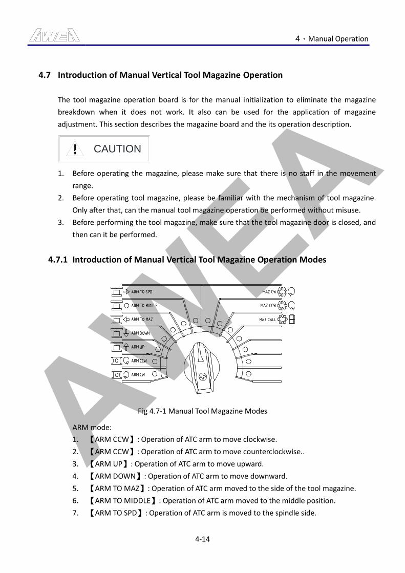
AWEA 4、Manual Operation
4-14
4.7 Introduction of Manual Vertical Tool Magazine Operation
The tool magazine operation board is for the manual initialization to eliminate the magazine
breakdown when it does not work. It also can be used for the application of magazine
adjustment. This section describes the magazine board and the its operation description.
CAUTION
1. Before operating the magazine, please make sure that there is no staff in the movement
range.
2. Before operating tool magazine, please be familiar with the mechanism of tool magazine.
Only after that, can the manual tool magazine operation be performed without misuse.
3. Before performing the tool magazine, make sure that the tool magazine door is closed, and
then can it be performed.
4.7.1 Introduction of Manual Vertical Tool Magazine Operation Modes
Fig 4.7-1 Manual Tool Magazine Modes
ARM mode:
1. 【ARM CCW】: Operation of ATC arm to move clockwise.
2. 【ARM CCW】: Operation of ATC arm to move counterclockwise..
3. 【ARM UP】: Operation of ATC arm to move upward.
4. 【ARM DOWN】: Operation of ATC arm to move downward.
5. 【ARM TO MAZ】: Operation of ATC arm moved to the side of the tool magazine.
6. 【ARM TO MIDDLE】: Operation of ATC arm moved to the middle position.
7. 【ARM TO SPD】: Operation of ATC arm is moved to the spindle side.
AWEA 4、Manual Operation
4-15
MAZ mode:
1. 【MAZ CW】: tool magazine CW operation.
2. 【MAZ CCW】: CCW operation of the tool magazine.
3. 【MAZ CALL】: Tool call operation. (Optional)
4.7.2 Introduction of Manual Vertical Tool Magazine Operation Mode Conditions
The prerequisites for Arm CW and CCW moving:
1. Arm position is at the middle or on the side of spindle.
2. ARM is in downward state.
3. Hydraulic pressure is normal.
4. No manual magazine alarm.
5. Interlock is not active.
6. MAZ door is must in closed.
Conditions for ATC Arm Upward/Downward:
1. ATC Arm is positioned in the tool magazine, middle position, or spindle side.
2. ATC Arm is in rotational positioning state.
3. When the arm is on the side of magazine, the chain must in stop state.
4. No manual tool magazine alarm.
5. Air pressure is in normal status.
6. Interlock is not active.
7. Tool magazine door is must in closed.
Conditions for ATC Arm horizontal movement:
1. ATC Arm is in rotational positioning state.
2. ATC Arm is in upward/downward positioning state.
3. Oil and air pressure are in normal status.
4. Interlock is not active.
5. No manual tool magazine alarm.
6. Tool magazine door is must in closed.
Prerequisites for manual tool package unclamp:
1. Tool magazine door is open.
2. Step on the pedal on the side of magazine.
3. Chain is in stop state.
4. Air pressure is in normal status.
AWEA 4、Manual Operation
4-16
5. The magazine is not in tool returning and tool selection modes.
6. Tool magazine door is must in closed.
Tool magazine Reversible conditions:
1. The position is at the middle or on the side of spindle.
2. Hydraulic pressure is normal.
3. Manual/automatic tool package is in clamping state.
4. No manual magazine alarm.
5. Interlock is not active.
6. Tool magazine door is must in closed.
4.7.3 Introduction of Manual Vertical Tool Magazine Operation
1. The mode is switched to manual modes “HANDLE, RAPID and JOG”.
2. Switch【PERMISSION KEY SWITCH OF TOOL MAGAZINE PANEL】 to position “1”.
3. After the selection of magazine mode, perform the button “MANUAL START” to start
the operation when the mode is active.
4. Complete the operation of the manual tool magazine.
Remark:
(1) After completing manual magazine operation, please switch “OPERATION MODE
KEY” to position 0 to prevent the alarm due to erroneous operations.
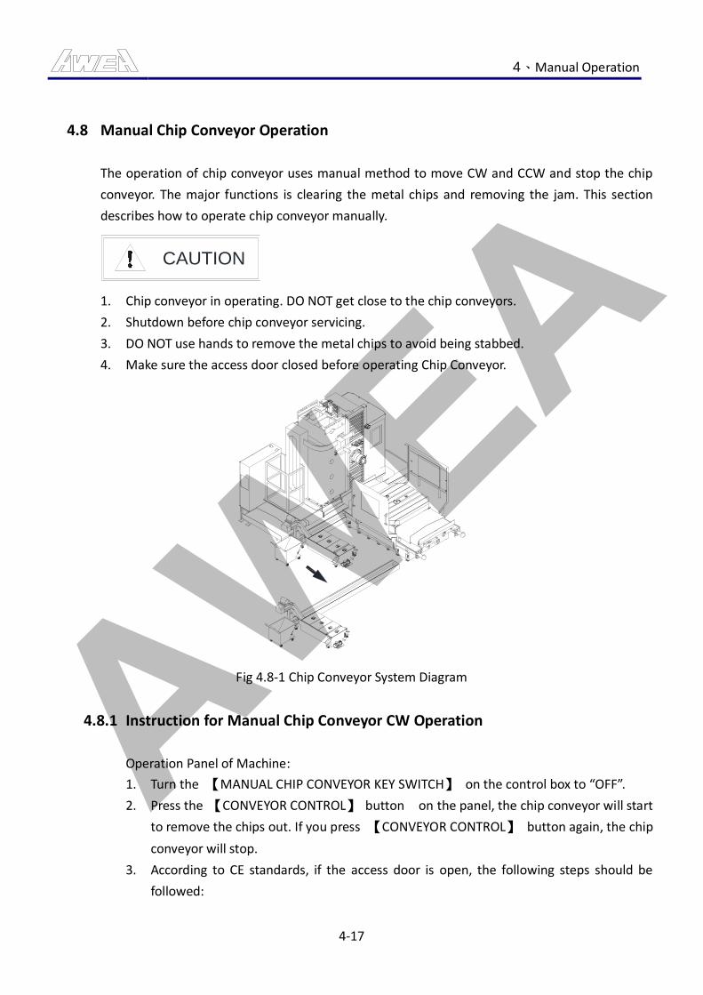
AWEA 4、Manual Operation
4-17
4.8 Manual Chip Conveyor Operation
The operation of chip conveyor uses manual method to move CW and CCW and stop the chip
conveyor. The major functions is clearing the metal chips and removing the jam. This section
describes how to operate chip conveyor manually.
CAUTION
1. Chip conveyor in operating. DO NOT get close to the chip conveyors.
2. Shutdown before chip conveyor servicing.
3. DO NOT use hands to remove the metal chips to avoid being stabbed.
4. Make sure the access door closed before operating Chip Conveyor.
Fig 4.8-1 Chip Conveyor System Diagram
4.8.1 Instruction for Manual Chip Conveyor CW Operation
Operation Panel of Machine:
1. Turn the 【MANUAL CHIP CONVEYOR KEY SWITCH】 on the control box to “OFF”.
2. Press the 【CONVEYOR CONTROL】 button on the panel, the chip conveyor will start
to remove the chips out. If you press 【CONVEYOR CONTROL】 button again, the chip
conveyor will stop.
3. According to CE standards, if the access door is open, the following steps should be
followed:
AWEA 4、Manual Operation
4-18
(1) Specify 【AUTO AND SETTING MODE KEY SWITCH】 in “Setting Mode”.
(2) Perform manual conveyor operation by JOG with 【SAFETY OPERATION BUTTON】
and 【CHIP CONVEYOR BUTTON】.
4. During the operation of conveyor, the indicator light of the button “CONVEYOR
CONTROL” will be on (constantly).
5. Chip conveyor Manual CW operation on Mechanical Operation Panel is completed.
Operation of chip conveyor operation box:
1. Turn the 【MANUAL CHIP CONVEYOR KEY SWITCH】 on the operation box of chip
conveyor to “ON”.
2. Press the button 【CW】 on the operation box of chip conveyor, the chip conveyor will
start to remove the chips out. If you press the button 【CW】 again, the chip conveyor
will stop.
3. During the operation of chip conveyor, the indicator light of the operation box will be
on (constantly).
4. Chip conveyor Manual CW operation on the operation box of chip conveyor is
completed.
4.8.2 Instruction for Manual Chip Conveyor CCW Operation
1. Chip conveyor Stop states.
2. Press the button “CCW” on the control box to move the chip conveyor backward.
Release the button to stop it.
(used when a jam happens)
3. During the Chip conveyor operation, indicator (constantly).
4. Complete the Manual Chip conveyor CCW operation.
4.8.3 Console Iron Removal Method
1. Use cleaning tools to move the chips (metal) to chip screw.
2. Start the spiral cuttings device motor, and to clear chip (iron).
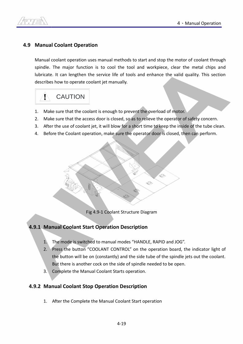
AWEA 4、Manual Operation
4-19
4.9 Manual Coolant Operation
Manual coolant operation uses manual methods to start and stop the motor of coolant through
spindle. The major function is to cool the tool and workpiece, clear the metal chips and
lubricate. It can lengthen the service life of tools and enhance the valid quality. This section
describes how to operate coolant jet manually.
CAUTION
1. Make sure that the coolant is enough to prevent the overload of motor.
2. Make sure that the access door is closed, so as to relieve the operator of safety concern.
3. After the use of coolant jet, it will blow for a short time to keep the inside of the tube clean.
4. Before the Coolant operation, make sure the operator door is closed, then can perform.
Fig 4.9-1 Coolant Structure Diagram
4.9.1 Manual Coolant Start Operation Description
1. The mode is switched to manual modes “HANDLE, RAPID and JOG”.
2. Press the button “COOLANT CONTROL” on the operation board, the indicator light of
the button will be on (constantly) and the side tube of the spindle jets out the coolant.
But there is another cock on the side of spindle needed to be open.
3. Complete the Manual Coolant Starts operation.
4.9.2 Manual Coolant Stop Operation Description
1. After the Complete the Manual Coolant Start operation

AWEA 4、Manual Operation
4-20
2. Press the button “COOLANT CONTROL” again, the indicator light turns off and the
spraying of coolant is stopped.
3. Complete the Manual Coolant Stop operation.
4.9.3 Manual Coolant Gun Start Operation Description
1. Press the button 【COOLANT GUN CONTROL】 , the indicator light will be on
(constantly).
2. Open the cock of coolant gun.
3. Complete the coolant gun start operation.
4.9.4 Manual Coolant Gun Stop Operation Description
1. After the complete the coolant gun start operation.
2. Perform 【COOLANT GUN CONTROL】key again, the key light (light off).
3. Coolant gun hancock close.
4. Complete the coolant gun stop operation.
AWEA 4、Manual Operation
4-21
4.10 MPG Feed Operation
The function of MPG Feed is for the measurement of workpiece. In the purpose of that not to
damage the work piece, the axial should be in jog and slow move so as to reach the
measurement accuracy. This section introduces how to operate MPG Feed.
CAUTION
1. Before performing the axial move, make sure that there is no staff inside of or around the
machine, then can it be performed.
2. Before performing the axial move, make sure that the access door is closed, then can it be
performed.
4.10.1 Introduction for MPG Feed Operation
1. Turn the mode selection button to『HANDLE』mode
2. Select axis selection button:
This button is used to select the target axis for MPG operation. When using MPG, you
can only move single axis every time.
3. Adjust rate selection button:
To select how much distance (0.001mm∕0.01mm∕0.1mm) the axis move when the MPG
is rotated one round.
4. According to CE standards, if the access door is open, the following steps should be
followed:
(1) Specify 【AUTO AND SETTING MODE KEY SWITCH】 in “Setting Mode”.
(2) You need to operate the MPG in JOG mode with the button “MPG ENABLE”.
(3) MPG Feed the maximum speed limit 2m/min.
5. Rotating the MPG one round (360°) produces 100 pulses. Clockwise rotation move the
axis in "+" direction, and counterclockwise rotation move the axis in the "-" direction.
Remark:
(1) If MPG is more than 5 rounds per second, the moving distance of the machine
will be different from that of rotary.
(2) If one selects the rate of x100 and rotates it too fast, it will move with the speedy
ratio. If it stops suddenly, the machine will shake
6. Complete the MPG feed operation.
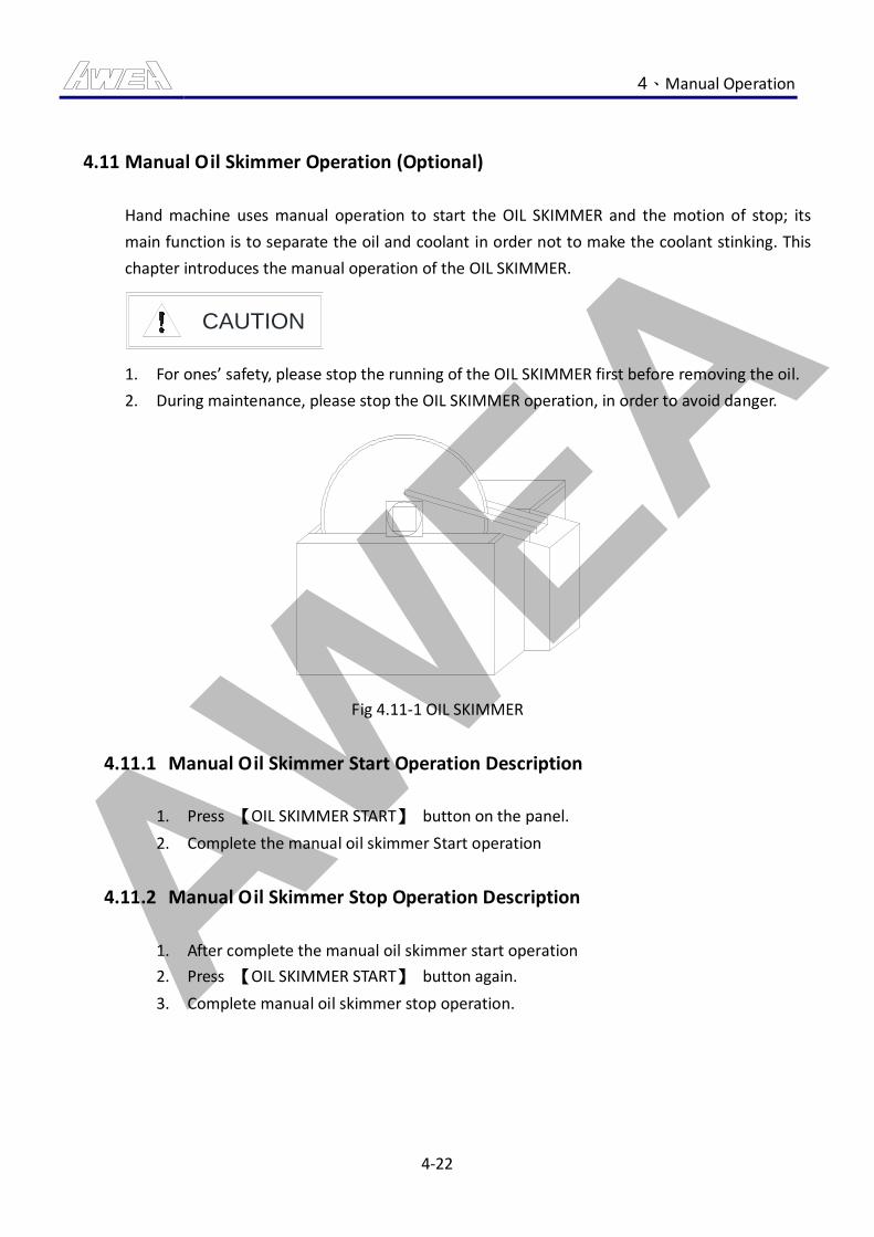
AWEA 4、Manual Operation
4-22
4.11 Manual Oil Skimmer Operation (Optional)
Hand machine uses manual operation to start the OIL SKIMMER and the motion of stop; its
main function is to separate the oil and coolant in order not to make the coolant stinking. This
chapter introduces the manual operation of the OIL SKIMMER.
CAUTION
1. For ones’ safety, please stop the running of the OIL SKIMMER first before removing the oil.
2. During maintenance, please stop the OIL SKIMMER operation, in order to avoid danger.
Fig 4.11-1 OIL SKIMMER
4.11.1 Manual Oil Skimmer Start Operation Description
1. Press 【OIL SKIMMER START】 button on the panel.
2. Complete the manual oil skimmer Start operation
4.11.2 Manual Oil Skimmer Stop Operation Description
1. After complete the manual oil skimmer start operation
2. Press 【OIL SKIMMER START】 button again.
3. Complete manual oil skimmer stop operation.
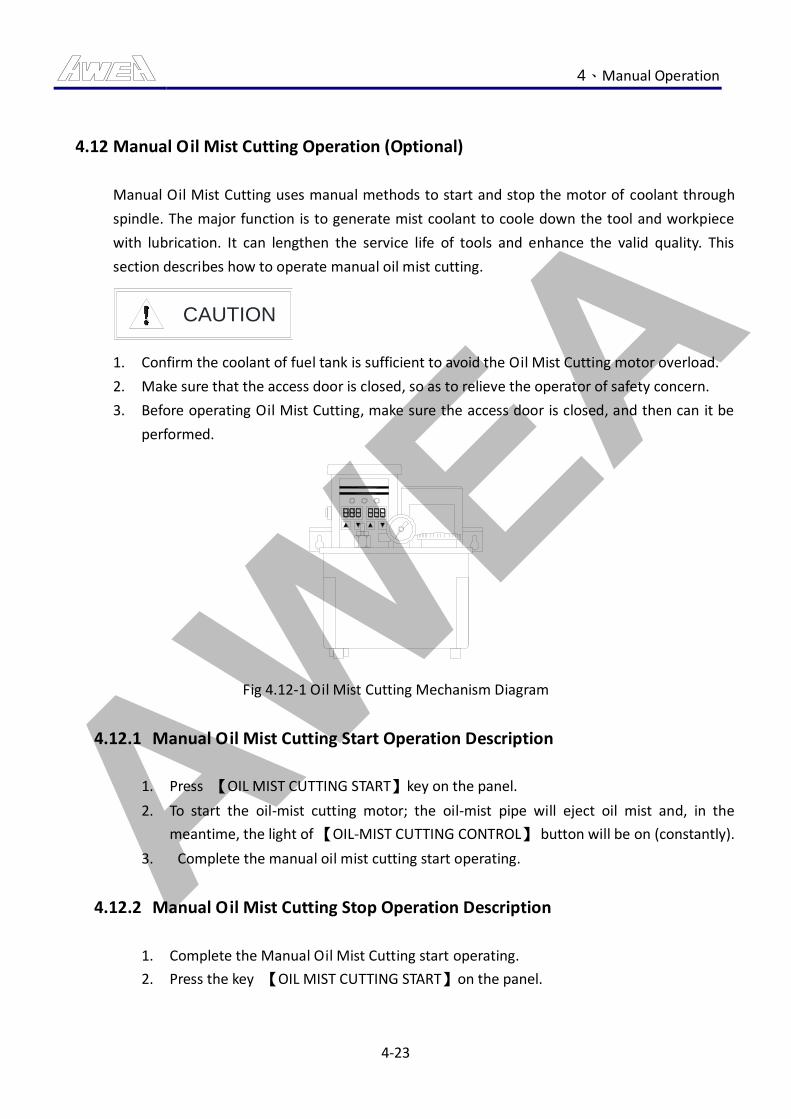
AWEA 4、Manual Operation
4-23
4.12 Manual Oil Mist Cutting Operation (Optional)
Manual Oil Mist Cutting uses manual methods to start and stop the motor of coolant through
spindle. The major function is to generate mist coolant to coole down the tool and workpiece
with lubrication. It can lengthen the service life of tools and enhance the valid quality. This
section describes how to operate manual oil mist cutting.
CAUTION
1. Confirm the coolant of fuel tank is sufficient to avoid the Oil Mist Cutting motor overload.
2. Make sure that the access door is closed, so as to relieve the operator of safety concern.
3. Before operating Oil Mist Cutting, make sure the access door is closed, and then can it be
performed.
Fig 4.12-1 Oil Mist Cutting Mechanism Diagram
4.12.1 Manual Oil Mist Cutting Start Operation Description
1. Press 【OIL MIST CUTTING START】key on the panel.
2. To start the oil-mist cutting motor; the oil-mist pipe will eject oil mist and, in the
meantime, the light of 【OIL-MIST CUTTING CONTROL】 button will be on (constantly).
3. Complete the manual oil mist cutting start operating.
4.12.2 Manual Oil Mist Cutting Stop Operation Description
1. Complete the Manual Oil Mist Cutting start operating.
2. Press the key 【OIL MIST CUTTING START】on the panel.

AWEA 4、Manual Operation
4-24
3. Oil Mist Cutting motor is stopped, the oil mist stop spraying, and at the same time,
after the Oil Mist Cutting motor stopped, 【OIL MIST CUTTING CONTROL】 key light
(off).
4. The stop of manual oil-mist cutting is completed.
AWEA 5、Auto Operation
5-1
5. Auto Operation
5.1 Auto Program Operation Circulation
The function of Auto Program Circulation is to provide automatic circulation in processing in
order to increase the efficiency, lower the cost and increase competitiveness. This chapter
introduces the operation of automatic circulation.
CAUTION
1. Before performing the Auto Program Circulation, make sure that there is no staff inside of
or around the machine, and then can it be performed.
2. Before performing the Auto Program Circulation, make sure that the access door is closed,
and then can it be performed.
5.1.1 Instruction for Auto Program Operation Circulation
1. According to CE standards, the following steps should be followed:
(1) Specify 【AUTO AND SETTING MODE KEY SWITCH】 in “Auto Mode”.
(2) Close the safety door of operation.
2. Rotate the mode switch to “EDIT” or “MDI” mode.
3. Draft processing program.
4. Rotate the mode to “MEM or MDI” mode.
5. Press the key 【CYCLE START】, and run the program.
6. When the program is running, the light of the button of 【CYCLE START】 and green
light will be on (constantly).
7. Complete the auto program circle operation.
AWEA 5、Auto Operation
5-2
5.2 Auto Feed Operation
Auto Feed function, mainly used in the processing, a function of axial movement and
positioning, must comply with the Spindle RPM to adjust the feed rate, can achieve automatic
processing. This section describes how to perform the Auto Feed Operation.
CAUTION
1. When the heads are in unclamp state, the movement of Y and Z-axes can not be done.
2. If the spindle is in unclamp state or during the execution of software functions “AXES ILK”
and “Z CANCEL”, JOG feed can not be done.
3. Before performing the axial move, make sure that there is no staff inside of or around the
machine, then can it be performed.
4. Before performing the axial move, make sure that the access door is closed, then can it be
performed.
DANGER
1. When Table moves, DO NOT close to the table to avoid danger.
5.2.1 Auto Feed Operation Description
1. Mode switched to EDIT mode.
2. To follow G command of FANUC axis move. Under the program, edit the move
command.(Please refer to the manual of G command of FANUC for further
information.)
Example Description:
(1) G91 G0 X-1000.; (Rapid move of X axis for minus 1000mm.)
3. Adjust the Feed or Rapid Feed Knob.
4. Perform auto program circle operation.
5. The direction of axis will move based on the setting of operator and the light will be on
(constantly) when it is moving. When it goes to the set position, the light of the button
will be off (lights out).
6. Complete the auto feed operation.
AWEA 5、Auto Operation
5-3
5.3 Auto Spindle Running Operation
Auto Spindle Running function, mainly used in the processing, Auto spindle with axial
movement and positioning, to achieve automatic processing functions. This section describes
how to perform Auto Spindle Running.
DANGER
1. During the spindle rotating, DO NOT close to the spindle.
2. Shut machine off when entering spindle area for servicing.
3. Before rotating the spindle, please make sure that the tool is well clamped and do safety
checks like there should be no obstruction in its movement range, etc.
4. During the spindle operation, if the mode is switched to auto modes, the spindle will stop
immediately.
5. Before operating spindle rotation, please make sure that there is no staff on the console.
6. Before performing the spindle rotation, make sure that the access door is closed exactly,
and then can it be performed.
CAUTION
1. Before the spindle rotating, make sure that the access door is closed exactly, then can the
spindle rotate.
5.3.1 Instruction for Auto Spindle CW Operation
1. Mode switched to EDIT mode.
2. Under the program, edit the M3 Ss - Command. (s: RPM)
3. Perform auto program circle operation.
4. The spindle will rotate clockwise following the command and the light of 【SPINDLE
CW】 will be on (constantly).
5. Complete the auto spindle CW operation.
5.3.2 Instruction for Auto Spindle CCW Operation
1. Mode switched to EDIT mode.
2. Under the program, edit the M4 Ss - Command.(s: RPM)
3. Perform auto program circle operation.
AWEA 5、Auto Operation
5-4
4. The spindle will rotate counterclockwise following the rpm command from the
operator. The light of 【SPINDLE CCW】 will be on (constantly).
5. Complete the auto spindle CCW operation.
5.3.3 Instruction for Auto Spindle Stop Operation
1. When Spindle Running.
2. Mode switched to EDIT mode.
3. Under the program, edit M5 Command.
4. Perform auto program circle operation.
5. The spindle will stop rotation. When it stops, the 【SPINDLE STOP】 button lights will
be on (constantly).
6. Complete the auto spindle stop operation.
Remark:
(1) Any time as long as the spindle does not rotate, the key 【SPINDLE STOP】 lights
will be (constantly), and it means Spindle in stop state at current time.
(2) Press the key 【RESET】or the emergency switch on the MDI panel will make the
spindle stop rotating.
5.3.4 Instruction for Auto Spindle Positioning Operation
1. Mode switched to EDIT mode.
2. Under the program, edit M19 Command.
3. Perform auto program circle operation.
4. The spindle will position itself; after the positioning, the light of the button of
【SPINDLE POSITIONING】 will be on (constantly).
5. Complete the auto spindle positioning operation.
Remark:
(1) The status of spindle positioning will be cancelled if manual/auto spindle rotary is
performed.
(2) Press the key 【RESET】or the emergency switch on the MDI panel will cancel the
spindle positioning state.
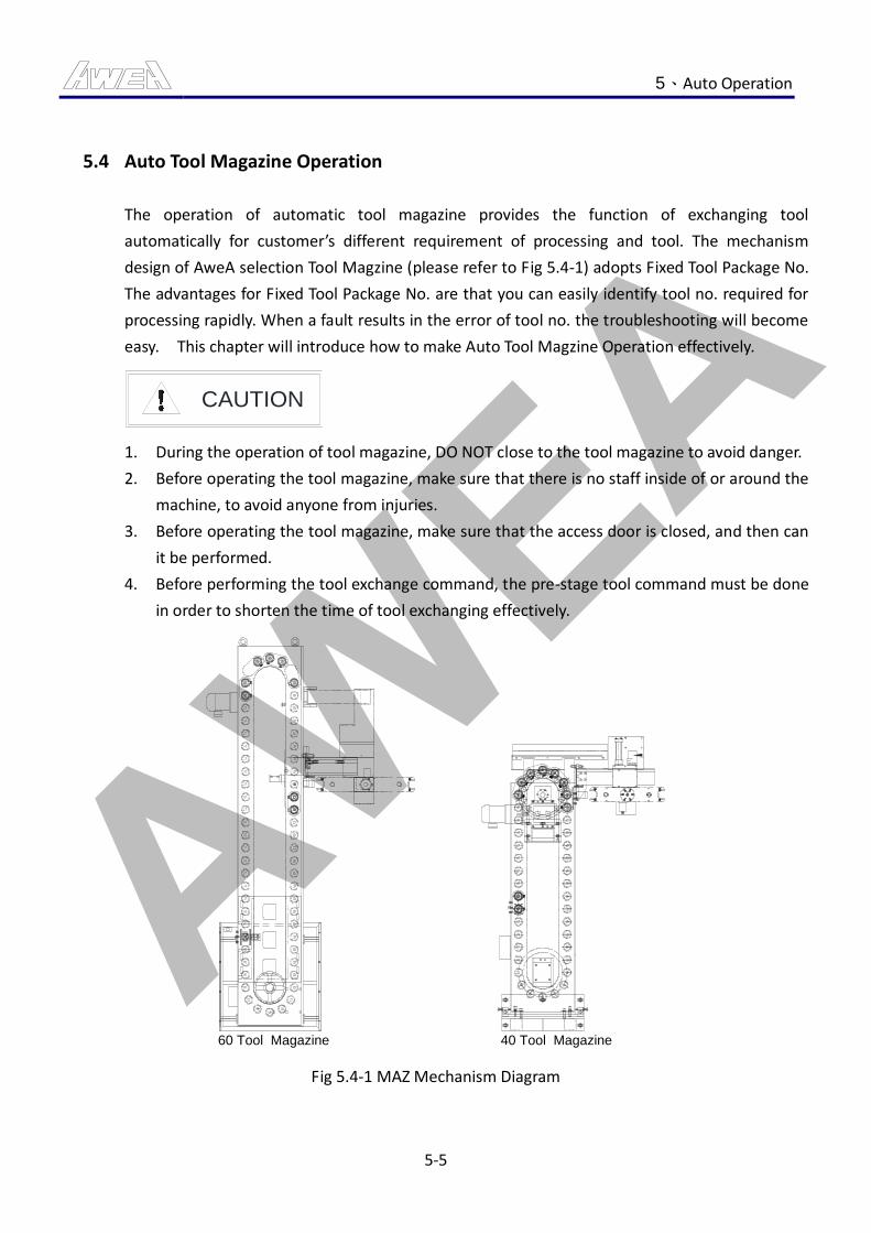
AWEA 5、Auto Operation
5-5
5.4 Auto Tool Magazine Operation
The operation of automatic tool magazine provides the function of exchanging tool
automatically for customer’s different requirement of processing and tool. The mechanism
design of AweA selection Tool Magzine (please refer to Fig 5.4-1) adopts Fixed Tool Package No.
The advantages for Fixed Tool Package No. are that you can easily identify tool no. required for
processing rapidly. When a fault results in the error of tool no. the troubleshooting will become
easy. This chapter will introduce how to make Auto Tool Magzine Operation effectively.
CAUTION
1. During the operation of tool magazine, DO NOT close to the tool magazine to avoid danger.
2. Before operating the tool magazine, make sure that there is no staff inside of or around the
machine, to avoid anyone from injuries.
3. Before operating the tool magazine, make sure that the access door is closed, and then can
it be performed.
4. Before performing the tool exchange command, the pre-stage tool command must be done
in order to shorten the time of tool exchanging effectively.
60 Tool Magazine 40 Tool Magazine
Fig 5.4-1 MAZ Mechanism Diagram
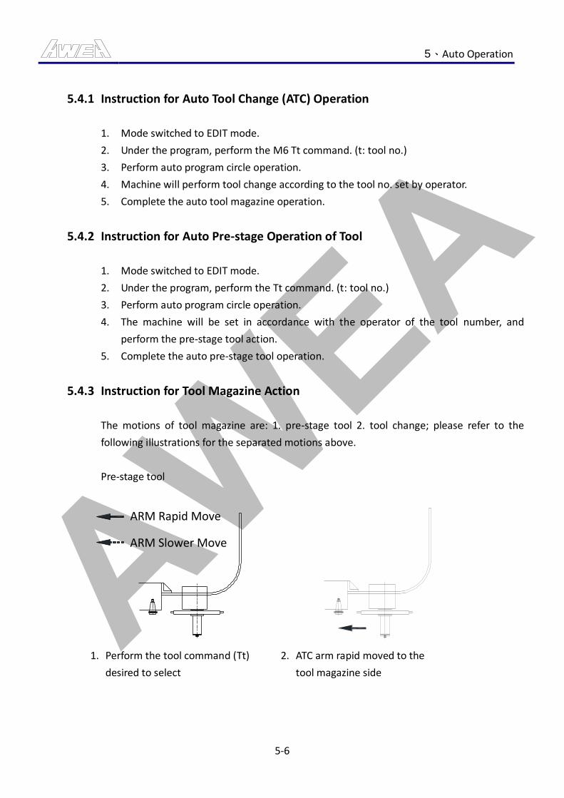
AWEA 5、Auto Operation
5-6
5.4.1 Instruction for Auto Tool Change (ATC) Operation
1. Mode switched to EDIT mode.
2. Under the program, perform the M6 Tt command. (t: tool no.)
3. Perform auto program circle operation.
4. Machine will perform tool change according to the tool no. set by operator.
5. Complete the auto tool magazine operation.
5.4.2 Instruction for Auto Pre-stage Operation of Tool
1. Mode switched to EDIT mode.
2. Under the program, perform the Tt command. (t: tool no.)
3. Perform auto program circle operation.
4. The machine will be set in accordance with the operator of the tool number, and
perform the pre-stage tool action.
5. Complete the auto pre-stage tool operation.
5.4.3 Instruction for Tool Magazine Action
The motions of tool magazine are: 1. pre-stage tool 2. tool change; please refer to the
following illustrations for the separated motions above.
Pre-stage tool
ARM Slower Move
ARM Rapid Move
1. Perform the tool command (Tt)
desired to select
2. ATC arm rapid moved to the
tool magazine side
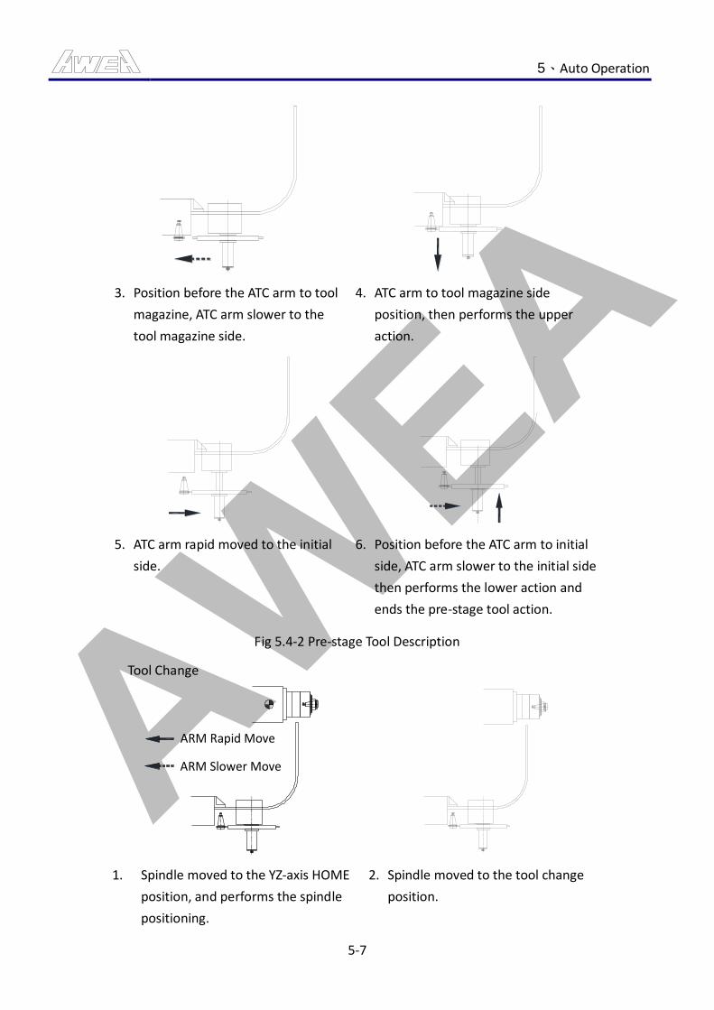
AWEA 5、Auto Operation
5-7
3. Position before the ATC arm to tool
magazine, ATC arm slower to the
tool magazine side.
4. ATC arm to tool magazine side
position, then performs the upper
action.
5. ATC arm rapid moved to the initial
side.
6. Position before the ATC arm to initial
side, ATC arm slower to the initial side
then performs the lower action and
ends the pre-stage tool action.
Fig 5.4-2 Pre-stage Tool Description
Tool Change
ARM Rapid Move
ARM Slower Move
1. Spindle moved to the YZ-axis HOME
position, and performs the spindle
positioning.
2. Spindle moved to the tool change
position.
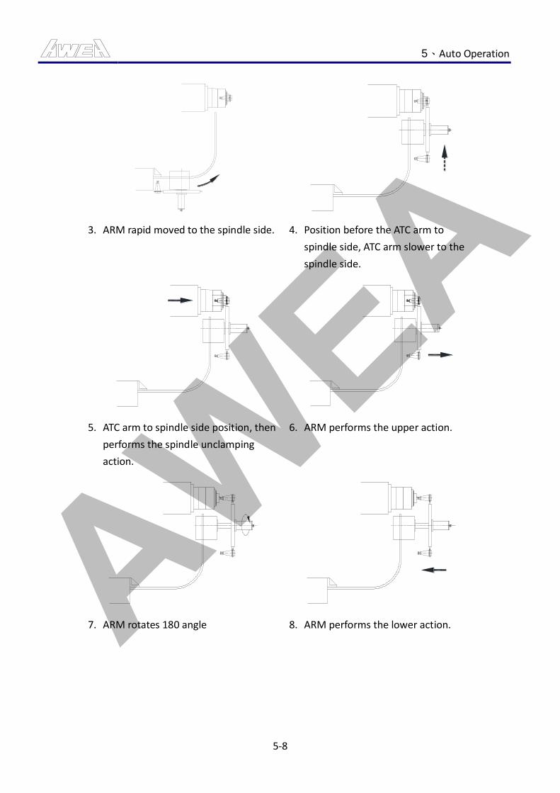
AWEA 5、Auto Operation
5-8
3. ARM rapid moved to the spindle side. 4. Position before the ATC arm to
spindle side, ATC arm slower to the
spindle side.
5. ATC arm to spindle side position, then
performs the spindle unclamping
action.
6. ARM performs the upper action.
7. ARM rotates 180 angle 8. ARM performs the lower action.
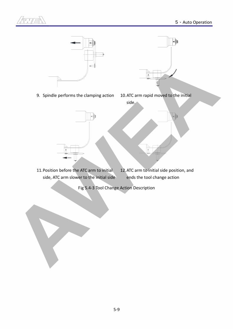
AWEA 5、Auto Operation
5-9
9. Spindle performs the clamping action 10. ATC arm rapid moved to the initial
side.
11. Position before the ATC arm to initial
side, ATC arm slower to the initial side
12. ATC arm to initial side position, and
ends the tool change action
Fig 5.4-3 Tool Change Action Description

AWEA 5、Auto Operation
5-10
5.4.4 Instruction for Tool Exchange Procedure
Program
Description Machine Action Description
Spindle Tool
NO.
ARM Tool
NO.
Tool Magazine
NO.
(Initial Status) 10 7 5
T10;
Spindle tool no. equal to prepare, so
DO NOT run the Preparation of tool
action
10 7 5
M06 T10;
Spindle number equal to the
exchange. Tool no., so the tool
change action will not be performed
10 7 5
T07;
Prepared tool no. is equal to the tool
change arm tool no., so the
pre-staged tool action will not be
performed
10 7 5
M06 T07; Perform the tool change action 7 10 5
T05;
Perform a pre-stage tool No. 5 Action
First implementation tool No. 10
return to action
Re-execution tool No. 5 pre-staged
tool action
7 5 5
M06 T05; Perform the tool change action 5 7 5
T9;
Perform pre-stage tool No. 9 action
First perform tool No. 5 Home Return
action
Re-execution tool No. 9 pre-staged
tool action
5 9 9
M06 T9; Perform the tool change action 9 5 9
T00; Perform the ATC arm tool Home
Return action 9 0 5
M06 T00; Perform tool return action 0 9 5
Table 5.4-1 Tool Exchange Procedure List
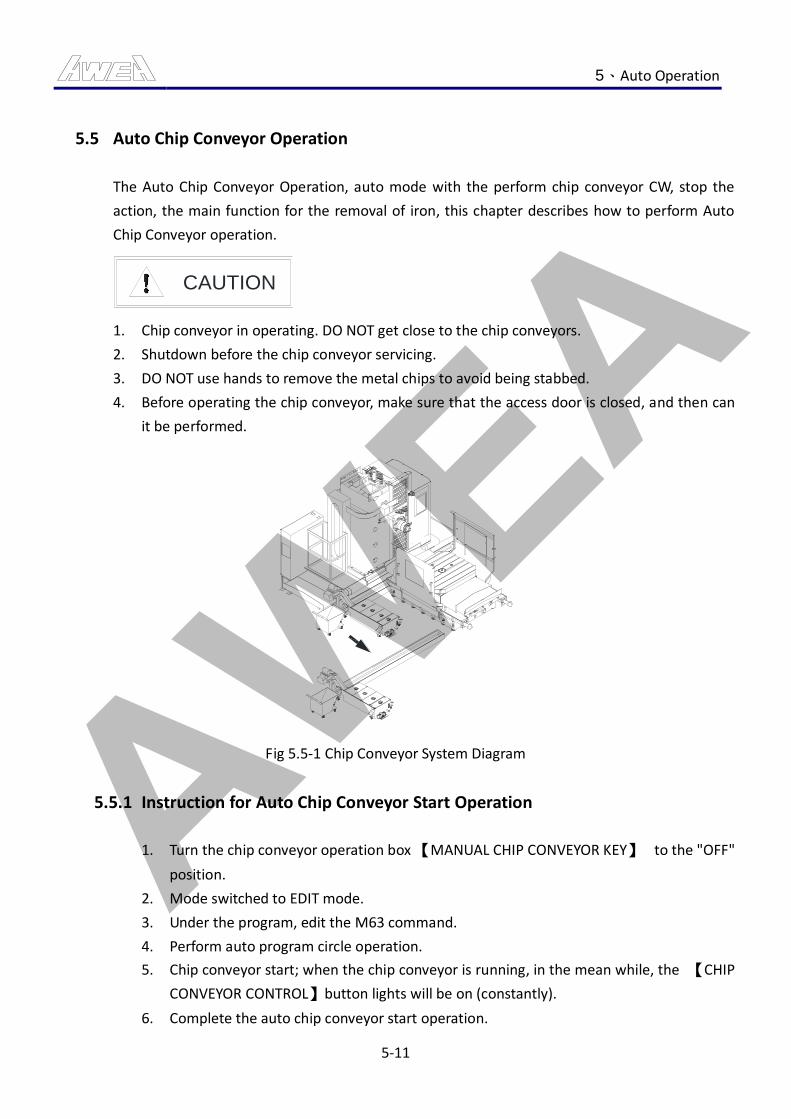
AWEA 5、Auto Operation
5-11
5.5 Auto Chip Conveyor Operation
The Auto Chip Conveyor Operation, auto mode with the perform chip conveyor CW, stop the
action, the main function for the removal of iron, this chapter describes how to perform Auto
Chip Conveyor operation.
CAUTION
1. Chip conveyor in operating. DO NOT get close to the chip conveyors.
2. Shutdown before the chip conveyor servicing.
3. DO NOT use hands to remove the metal chips to avoid being stabbed.
4. Before operating the chip conveyor, make sure that the access door is closed, and then can
it be performed.
Fig 5.5-1 Chip Conveyor System Diagram
5.5.1 Instruction for Auto Chip Conveyor Start Operation
1. Turn the chip conveyor operation box 【MANUAL CHIP CONVEYOR KEY】 to the "OFF"
position.
2. Mode switched to EDIT mode.
3. Under the program, edit the M63 command.
4. Perform auto program circle operation.
5. Chip conveyor start; when the chip conveyor is running, in the mean while, the 【CHIP
CONVEYOR CONTROL】button lights will be on (constantly).
6. Complete the auto chip conveyor start operation.

AWEA 5、Auto Operation
5-12
5.5.2 Instruction for Auto Chip Conveyor Stop Operation
1. After Complete the auto chip conveyor start operation.
2. Under the program, edit the M64 command.
3. Perform auto program circle operation.
4. Chip conveyor stop; when the chip conveyor is stopped, in the mean while, the 【CHIP
CONVEYOR CONTROL】button lights will be off (lights out).
5. Complete the auto chip conveyor stop operation.
5.5.3 Method for Iron Chip Removal on Console
1. Use cleaning tools to move the chips (iron chips) to chip screw.
2. Start the motor chip screw to clear the cutting chips (iron chips).
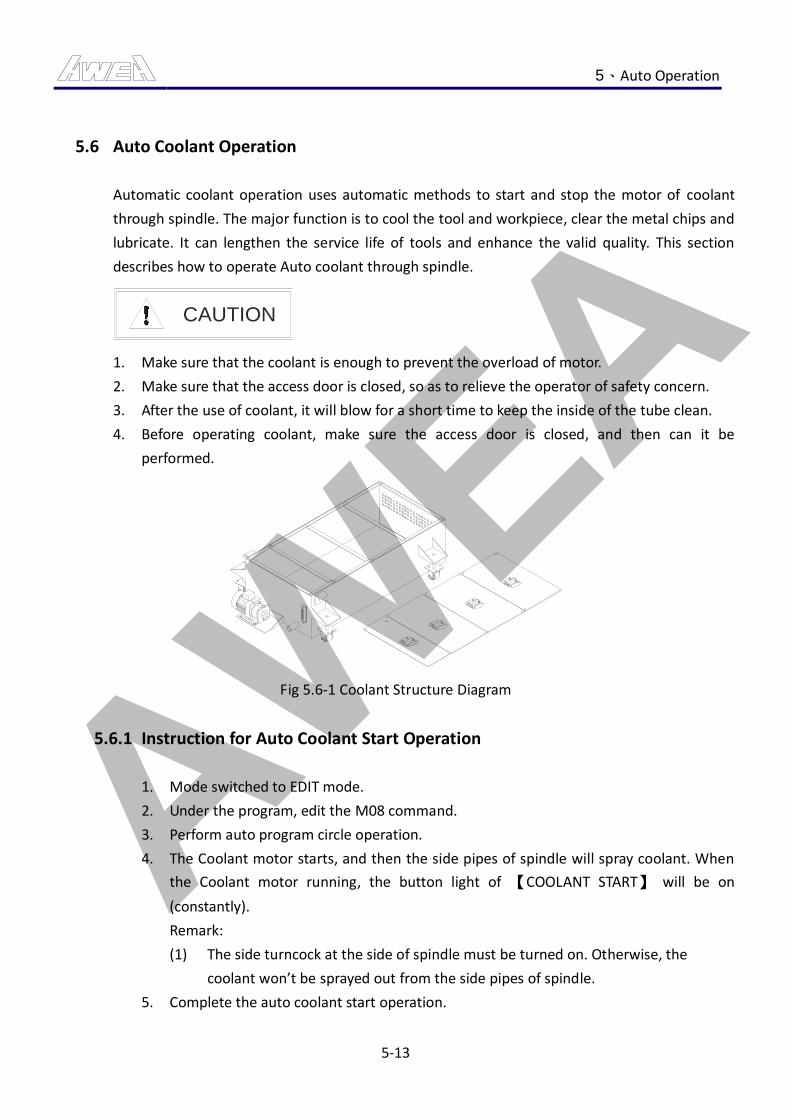
AWEA 5、Auto Operation
5-13
5.6 Auto Coolant Operation
Automatic coolant operation uses automatic methods to start and stop the motor of coolant
through spindle. The major function is to cool the tool and workpiece, clear the metal chips and
lubricate. It can lengthen the service life of tools and enhance the valid quality. This section
describes how to operate Auto coolant through spindle.
CAUTION
1. Make sure that the coolant is enough to prevent the overload of motor.
2. Make sure that the access door is closed, so as to relieve the operator of safety concern.
3. After the use of coolant, it will blow for a short time to keep the inside of the tube clean.
4. Before operating coolant, make sure the access door is closed, and then can it be
performed.
Fig 5.6-1 Coolant Structure Diagram
5.6.1 Instruction for Auto Coolant Start Operation
1. Mode switched to EDIT mode.
2. Under the program, edit the M08 command.
3. Perform auto program circle operation.
4. The Coolant motor starts, and then the side pipes of spindle will spray coolant. When
the Coolant motor running, the button light of 【COOLANT START】 will be on
(constantly).
Remark:
(1) The side turncock at the side of spindle must be turned on. Otherwise, the
coolant won’t be sprayed out from the side pipes of spindle.
5. Complete the auto coolant start operation.
AWEA 5、Auto Operation
5-14
5.6.2 Instruction for Auto Coolant Stop Operation
1. After Complete the auto coolant start operation.
2. Under the program, edit the M09 command.
3. Perform auto program circle operation.
4. The Coolant motor stops, and then the side pipes at the side of spindle will stop
spraying coolant. When the coolant motor stops, the button light of 【COOLANT
START】 will be off (lights out).
5. Complete the auto coolant stop operation.
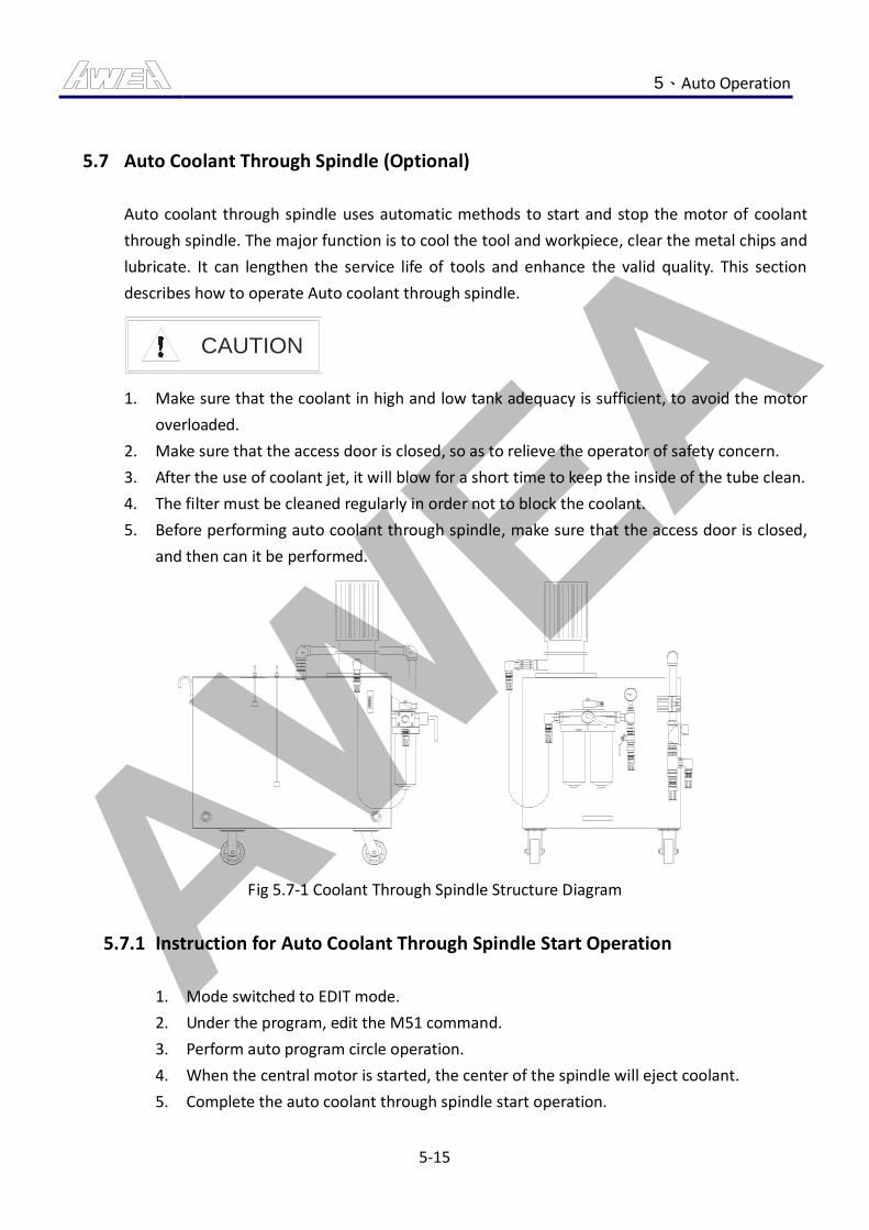
AWEA 5、Auto Operation
5-15
5.7 Auto Coolant Through Spindle (Optional)
Auto coolant through spindle uses automatic methods to start and stop the motor of coolant
through spindle. The major function is to cool the tool and workpiece, clear the metal chips and
lubricate. It can lengthen the service life of tools and enhance the valid quality. This section
describes how to operate Auto coolant through spindle.
CAUTION
1. Make sure that the coolant in high and low tank adequacy is sufficient, to avoid the motor
overloaded.
2. Make sure that the access door is closed, so as to relieve the operator of safety concern.
3. After the use of coolant jet, it will blow for a short time to keep the inside of the tube clean.
4. The filter must be cleaned regularly in order not to block the coolant.
5. Before performing auto coolant through spindle, make sure that the access door is closed,
and then can it be performed.
Fig 5.7-1 Coolant Through Spindle Structure Diagram
5.7.1 Instruction for Auto Coolant Through Spindle Start Operation
1. Mode switched to EDIT mode.
2. Under the program, edit the M51 command.
3. Perform auto program circle operation.
4. When the central motor is started, the center of the spindle will eject coolant.
5. Complete the auto coolant through spindle start operation.
AWEA 5、Auto Operation
5-16
5.7.2 Instruction for Auto Coolant Through Spindle Stop Operation
1. After complete the auto coolant through spindle start operation.
2. Under the program, edit the M09 command.
3. Perform auto program circle operation.
4. When the central motor stops, the ejection of the coolant will stop too.
5. After the coolant stops spraying, air blow will be last for a short time to keep the inside
of the tube clean.
6. Complete the auto coolant through spindle stop operation.
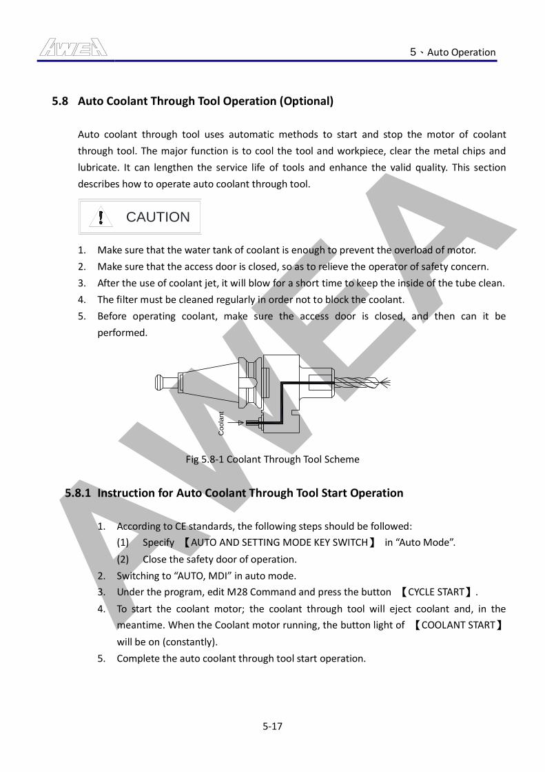
AWEA 5、Auto Operation
5-17
5.8 Auto Coolant Through Tool Operation (Optional)
Auto coolant through tool uses automatic methods to start and stop the motor of coolant
through tool. The major function is to cool the tool and workpiece, clear the metal chips and
lubricate. It can lengthen the service life of tools and enhance the valid quality. This section
describes how to operate auto coolant through tool.
CAUTION
1. Make sure that the water tank of coolant is enough to prevent the overload of motor.
2. Make sure that the access door is closed, so as to relieve the operator of safety concern.
3. After the use of coolant jet, it will blow for a short time to keep the inside of the tube clean.
4. The filter must be cleaned regularly in order not to block the coolant.
5. Before operating coolant, make sure the access door is closed, and then can it be
performed.
Co
ola
nt
Fig 5.8-1 Coolant Through Tool Scheme
5.8.1 Instruction for Auto Coolant Through Tool Start Operation
1. According to CE standards, the following steps should be followed:
(1) Specify 【AUTO AND SETTING MODE KEY SWITCH】 in “Auto Mode”.
(2) Close the safety door of operation.
2. Switching to “AUTO, MDI” in auto mode.
3. Under the program, edit M28 Command and press the button 【CYCLE START】.
4. To start the coolant motor; the coolant through tool will eject coolant and, in the
meantime. When the Coolant motor running, the button light of 【COOLANT START】
will be on (constantly).
5. Complete the auto coolant through tool start operation.
AWEA 5、Auto Operation
5-18
5.8.2 Instruction for Auto Coolant Through Tool Stop Operation
1. After complete the auto coolant through tool start operation.
2. To edit the M09 command and start the button of 【CYCLE START】.
3. The Coolant motor stops, and then coolant through tool will stop spraying coolant.
When the Coolant motor stops, the button light of 【COOLANT START】 will be off
(lights out).
4. Complete the auto coolant through tool stop operation.
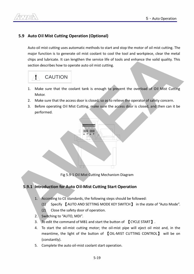
AWEA 5、Auto Operation
5-19
5.9 Auto Oil Mist Cutting Operation (Optional)
Auto oil mist cutting uses automatic methods to start and stop the motor of oil mist cutting. The
major function is to generate oil mist coolant to cool the tool and workpiece, clear the metal
chips and lubricate. It can lengthen the service life of tools and enhance the valid quality. This
section describes how to operate auto oil mist cutting.
CAUTION
1. Make sure that the coolant tank is enough to prevent the overload of Oil Mist Cutting
Motor.
2. Make sure that the access door is closed, so as to relieve the operator of safety concern.
3. Before operating Oil Mist Cutting, make sure the access door is closed, and then can it be
performed.
Fig 5.9-1 Oil Mist Cutting Mechanism Diagram
5.9.1 Introduction for Auto Oil-Mist Cutting Start Operation
1. According to CE standards, the following steps should be followed:
(1) Specify 【AUTO AND SETTING MODE KEY SWITCH】 in the state of “Auto Mode”.
(2) Close the safety door of operation.
2. Switching to “AUTO, MDI”.
3. To edit the command of M81 and start the button of 【CYCLE START】.
4. To start the oil-mist cutting motor; the oil-mist pipe will eject oil mist and, in the
meantime, the light of the button of 【OIL-MIST CUTTING CONTROL】 will be on
(constantly).
5. Complete the auto oil-mist coolant start operation.
AWEA 5、Auto Operation
5-20
5.9.2 Instruction for Auto Oil Mist Cutting Stop Operation
1. After complete the auto oil-mist coolant start operation.
2. To edit the command of M83 or M09 and start the button of 【CYCLE START】.
3. Oil Mist Cutting motor is stopped, the oil mist stop spraying, and at the same time,
after the Oil Mist Cutting motor stopped, 【OIL MIST CUTTING CONTROL】 key light
(off).
4. Complete the auto oil-mist coolant stop operation.
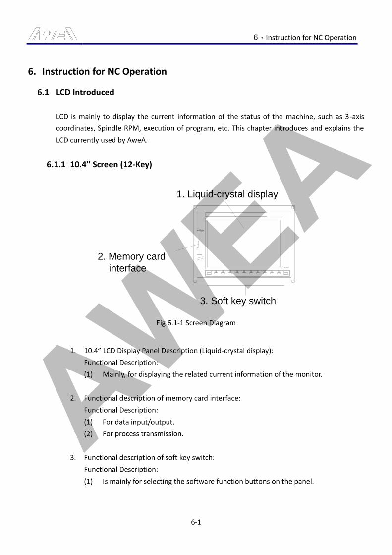
AWEA 6、Instruction for NC Operation
6-1
6. Instruction for NC Operation
6.1 LCD Introduced
LCD is mainly to display the current information of the status of the machine, such as 3-axis
coordinates, Spindle RPM, execution of program, etc. This chapter introduces and explains the
LCD currently used by AweA.
6.1.1 10.4" Screen (12-Key)
1. Liquid-crystal display
3. Soft key switch
2. Memory card
interface
Fig 6.1-1 Screen Diagram
1. 10.4” LCD Display Panel Description (Liquid-crystal display):
Functional Description:
(1) Mainly, for displaying the related current information of the monitor.
2. Functional description of memory card interface:
Functional Description:
(1) For data input/output.
(2) For process transmission.
3. Functional description of soft key switch:
Functional Description:
(1) Is mainly for selecting the software function buttons on the panel.
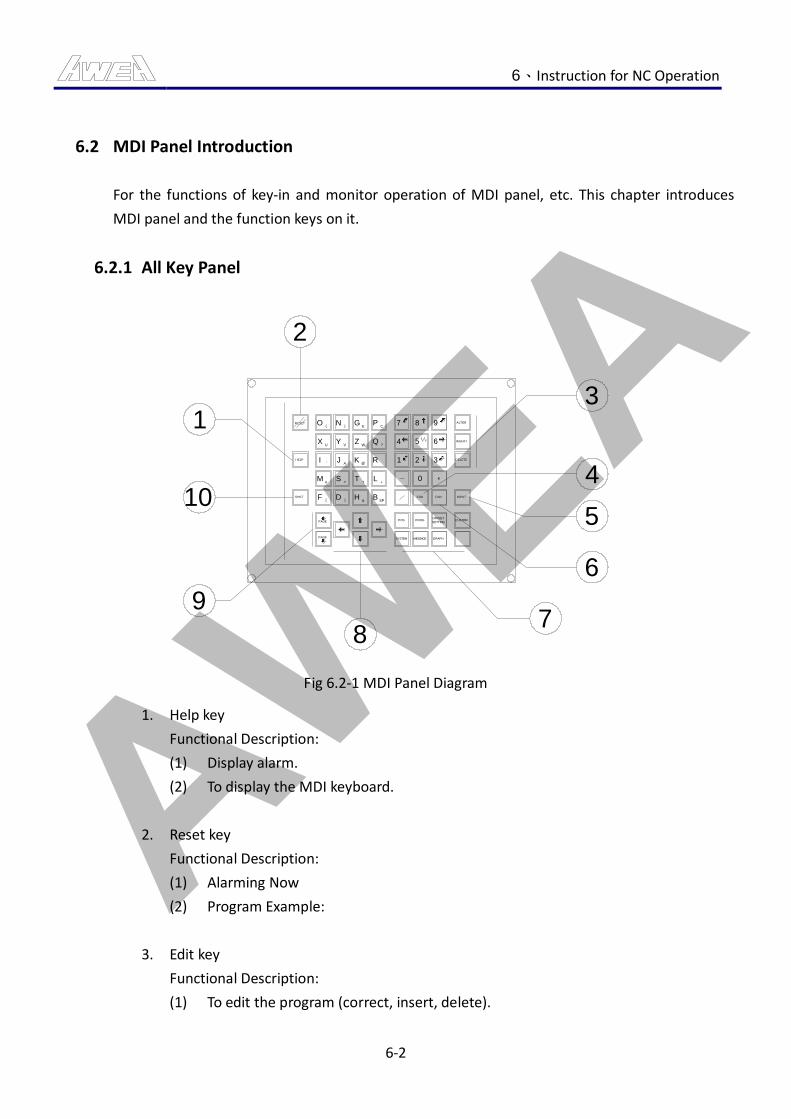
AWEA 6、Instruction for NC Operation
6-2
6.2 MDI Panel Introduction
For the functions of key-in and monitor operation of MDI panel, etc. This chapter introduces
MDI panel and the function keys on it.
6.2.1 All Key Panel
1
2
3
4
5
6
78
9
10
RESET
HELP
SHIFT
O(
XU
I ,
M#
F[
N)
YV
JA
S=
D]
GE
ZW
K@
T*
H&
PC
Q?
R
L+
BSP
7
4
1
8
5
2
9
6
3
0
EOB CAN INPUT
CUSTOMPOS PROG
SYSTEM MESSAGE GRAPH
DELETE
INSERT
ALTER
OFFSET
SETTINGPAGE
PAGE
Fig 6.2-1 MDI Panel Diagram
1. Help key
Functional Description:
(1) Display alarm.
(2) To display the MDI keyboard.
2. Reset key
Functional Description:
(1) Alarming Now
(2) Program Example:
3. Edit key
Functional Description:
(1) To edit the program (correct, insert, delete).
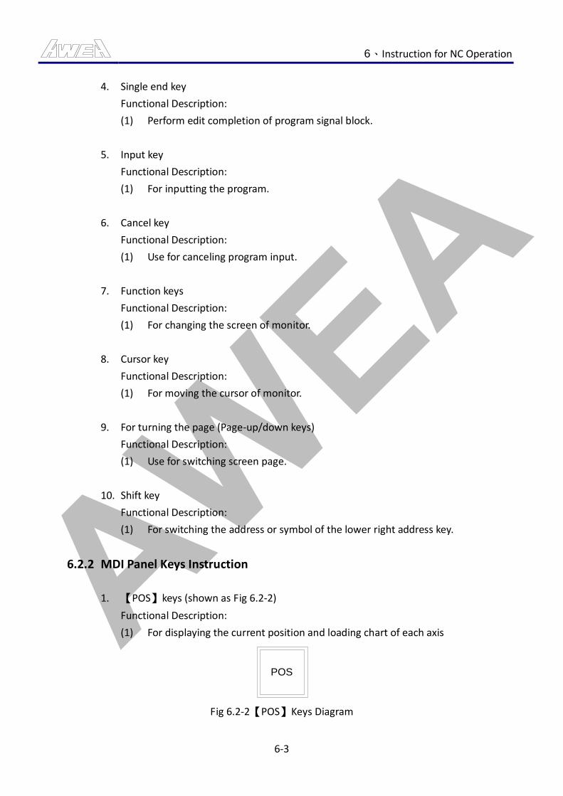
AWEA 6、Instruction for NC Operation
6-3
4. Single end key
Functional Description:
(1) Perform edit completion of program signal block.
5. Input key
Functional Description:
(1) For inputting the program.
6. Cancel key
Functional Description:
(1) Use for canceling program input.
7. Function keys
Functional Description:
(1) For changing the screen of monitor.
8. Cursor key
Functional Description:
(1) For moving the cursor of monitor.
9. For turning the page (Page-up/down keys)
Functional Description:
(1) Use for switching screen page.
10. Shift key
Functional Description:
(1) For switching the address or symbol of the lower right address key.
6.2.2 MDI Panel Keys Instruction
1. 【POS】keys (shown as Fig 6.2-2)
Functional Description:
(1) For displaying the current position and loading chart of each axis
POS
Fig 6.2-2【POS】Keys Diagram
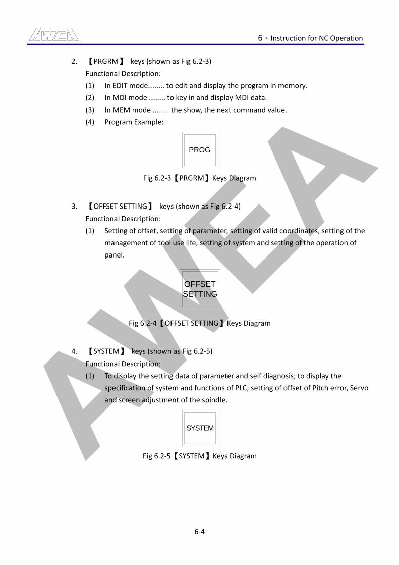
AWEA 6、Instruction for NC Operation
6-4
2. 【PRGRM】 keys (shown as Fig 6.2-3)
Functional Description:
(1) In EDIT mode........ to edit and display the program in memory.
(2) In MDI mode ........ to key in and display MDI data.
(3) In MEM mode ........ the show, the next command value.
(4) Program Example:
PROG
Fig 6.2-3【PRGRM】Keys Diagram
3. 【OFFSET SETTING】 keys (shown as Fig 6.2-4)
Functional Description:
(1) Setting of offset, setting of parameter, setting of valid coordinates, setting of the
management of tool use life, setting of system and setting of the operation of
panel.
OFFSET
SETTING
Fig 6.2-4【OFFSET SETTING】Keys Diagram
4. 【SYSTEM】 keys (shown as Fig 6.2-5)
Functional Description:
(1) To display the setting data of parameter and self diagnosis; to display the
specification of system and functions of PLC; setting of offset of Pitch error, Servo
and screen adjustment of the spindle.
SYSTEM
Fig 6.2-5【SYSTEM】Keys Diagram
AWEA 6、Instruction for NC Operation
6-5
5. 【GRAPH】 keys (shown as Fig 6.2-6)
Functional Description:
(1) Screen function.
GRAPH
Fig 6.2-6【GRAPH】Keys Diagram
6. 【MESSAGE】 keys (shown as Fig 6.2-7)
Functional Description:
(1) To display the alarming signal number and information of operation.
MESSAGE
Fig 6.2-7【MESSAGE】Keys Diagram
7. 【RESET】 keys (shown as Fig 6.2-8)
Functional Description:
(1) Press this button to reset CNC and cancel the alarming signal, etc.
RESET
Fig 6.2-8【RESET】Keys Diagram
8. 【CAN】 key (shown as Fig 6.2-9)
Functional Description:
(1) Press this button to delete the last keyed in character or symbol.
(2) When press CAN, the characters before "_" will be deleted immediately.
For E.g.: When >N001 X100.Z_ is displayed; if one press (CAN), the z will be
deleted and only >N001 X100._ is displayed.
CAN
Fig 6.2-9【CAN】Key Diagram

AWEA 6、Instruction for NC Operation
6-6
9. 【INPUT】 key (shown as Fig 6.2-10)
Functional Description:
(1) To key in the data of character or number into the memory (parameter, data);
this button is with the same function of INPUT; press either one will get the same
effect.
INPUT
Fig 6.2-10【INPUT】Key Diagram
10. 【MOVE CURSOR】 Key (shown as Fig 6.2-11)
Functional Description:
(1) To move the cursor up/down/left/right for 1 section.
Fig 6.2-11【MOVE CURSOR】Key Diagram
11. 【PAGE UP】 key (shown as Fig 6.2-12)
Functional Description:
(1) Turn to previous page of the screen.
PAGE
Fig 6.2-12【PAGE UP】Key Diagram
AWEA 6、Instruction for NC Operation
6-7
12. 【PAGE DOWN】 key (shown as Fig 6.2-13)
Functional Description:
(1) Turn to next page of the screen.
PAGE
Fig 6.2-13【PAGE DOWN】Key Diagram
13. 【ALTER】 key (shown as Fig 6.2-14)
Functional Description:
(1) Data Alternation.
ALTER
Fig 6.2-14【ALTER】Key Diagram
14. 【INSERT】 key (shown as Fig 6.2-15)
Functional Description:
(1) Data Insert.
INSERT
Fig 6.2-15【INSERT】Key Diagram
15. 【DELETE】 key (shown as Fig 6.2-16)
Functional Description:
(1) Data Deletion.
DELETE
Fig 6.2-16【DELETE】Key Diagram
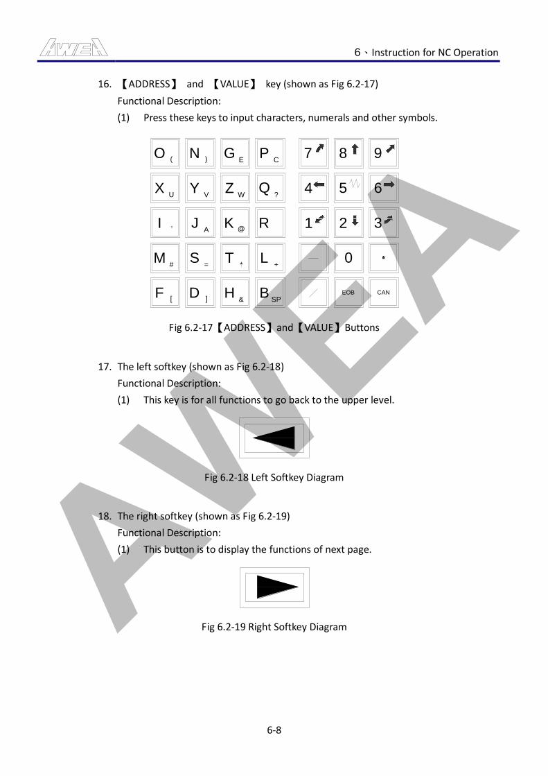
AWEA 6、Instruction for NC Operation
6-8
16. 【ADDRESS】 and 【VALUE】 key (shown as Fig 6.2-17)
Functional Description:
(1) Press these keys to input characters, numerals and other symbols.
O(
XU
I ,
M#
F[
N)
YV
JA
S=
D]
GE
ZW
K @
T*
H&
PC
Q?
R
L+
BSP
7
4
1
8
5
2
9
6
3
0
EOB CAN
Fig 6.2-17【ADDRESS】and【VALUE】Buttons
17. The left softkey (shown as Fig 6.2-18)
Functional Description:
(1) This key is for all functions to go back to the upper level.
Fig 6.2-18 Left Softkey Diagram
18. The right softkey (shown as Fig 6.2-19)
Functional Description:
(1) This button is to display the functions of next page.
Fig 6.2-19 Right Softkey Diagram
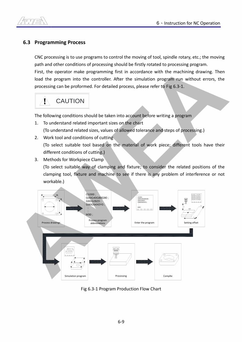
AWEA 6、Instruction for NC Operation
6-9
6.3 Programming Process
CNC processing is to use programs to control the moving of tool, spindle rotary, etc.; the moving
path and other conditions of processing should be firstly rotated to processing program.
First, the operator make programming first in accordance with the machining drawing. Then
load the program into the controller. After the simulation program run without errors, the
processing can be proformed. For detailed process, please refer to Fig 6.3-1.
CAUTION
The following conditions should be taken into account before writing a program
1. To understand related important sizes on the chart
(To understand related sizes, values of allowed tolerance and steps of processing.)
2. Work tool and conditions of cutting
(To select suitable tool based on the material of work piece; different tools have their
different conditions of cutting.)
3. Methods for Workpiece Clamp
(To select suitable way of clamping and fixture; to consider the related positions of the
clamping tool, fixture and machine to see if there is any problem of interference or not
workable.)
Process drawings
O1000 ;
G00G40G80G90 ;
G91G28Z0 ;
G90G54X0Y0 ;
:
:
M30 ;
O1000 ;
G00G40G80G90 ;
G91G28Z0 ;
G90G54X0Y0 ;
:
:
M30 ;
No. DATA No. DATA
001 200.00 017 142.12
002 192.12 018 200.22
003 133.33 019 212.23
004 122.33 020 212.33
005 182.22 021 168.68
G54
ZX
Y
Process programabbreviations Enter the program Setting offset
Simulation program Processing Complte
Fig 6.3-1 Program Production Flow Chart
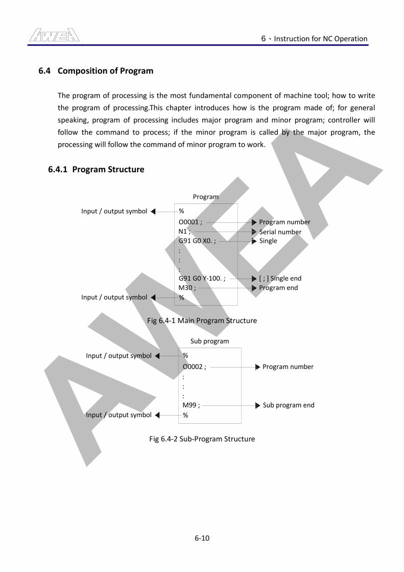
AWEA 6、Instruction for NC Operation
6-10
6.4 Composition of Program
The program of processing is the most fundamental component of machine tool; how to write
the program of processing.This chapter introduces how is the program made of; for general
speaking, program of processing includes major program and minor program; controller will
follow the command to process; if the minor program is called by the major program, the
processing will follow the command of minor program to work.
6.4.1 Program Structure
%
O0001 ;
N1 ;
G91 G0 X0. ;
:
:
:G91 G0 Y-100. ;
M30 ;
%
Input / output symbol
Input / output symbol
Program number
Serial numberSingle
[ ; ] Single end
Program end
Program
Fig 6.4-1 Main Program Structure
%
O0002 ;
:
:
:M99 ;
%
Input / output symbol
Input / output symbol
Program number
Sub program end
Sub program
Fig 6.4-2 Sub-Program Structure
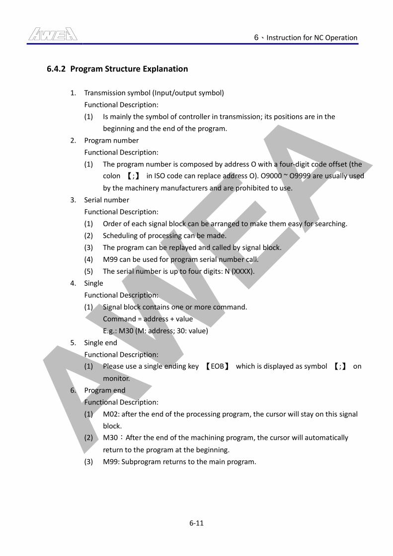
AWEA 6、Instruction for NC Operation
6-11
6.4.2 Program Structure Explanation
1. Transmission symbol (Input/output symbol)
Functional Description:
(1) Is mainly the symbol of controller in transmission; its positions are in the
beginning and the end of the program.
2. Program number
Functional Description:
(1) The program number is composed by address O with a four-digit code offset (the
colon 【;】 in ISO code can replace address O). O9000 ~ O9999 are usually used
by the machinery manufacturers and are prohibited to use.
3. Serial number
Functional Description:
(1) Order of each signal block can be arranged to make them easy for searching.
(2) Scheduling of processing can be made.
(3) The program can be replayed and called by signal block.
(4) M99 can be used for program serial number call.
(5) The serial number is up to four digits: N (XXXX).
4. Single
Functional Description:
(1) Signal block contains one or more command.
Command = address + value
E.g.: M30 (M: address; 30: value)
5. Single end
Functional Description:
(1) Please use a single ending key 【EOB】 which is displayed as symbol 【;】 on
monitor.
6. Program end
Functional Description:
(1) M02: after the end of the processing program, the cursor will stay on this signal
block.
(2) M30:After the end of the machining program, the cursor will automatically
return to the program at the beginning.
(3) M99: Subprogram returns to the main program.

AWEA 6、Instruction for NC Operation
6-12
6.4.3 Subprogram Call
If the cutting path is the same, a subprogram’s command can be used to simplify the coding
of the program.
Command format:
1. M98 PXXXX □□□□;
:
:
M99;
PXXXX: Times of subprogram performed (Four digits).
□□□□: The subprogram number to call (Four digits).
M99: Sub-program end and back to the main program.
2. M98 P□□□□ LXXXX;
:
:
M99;
P□□□□:Sub-program Number of Pre-call (4 digits)
LXXXX: Times of subprogram performed (4 digits).
M99: Sub-program end and back to the main program.
Main Program
%
O0001 ;
:
:
M98 P0002 ;
:
Subroutine
%
O0002 ;
:
:
M98 P0003 ;
:
Subroutine
%
O0003 ;
:
:
M98 P0004 ;
:
Subroutine
%
O0004 ;
:
:
M98 P0005 ;
:
Subroutine
%
O0005 ;
:
:
:
:
Fist Order Second Order Third Order Fourth Order
Fig 6.4-3 Subprogram Call Example
3. If no subprogram is specified, execution count is one.
4. Subprogram call can be up to four orders.
5. If the subprogram number can not be found, the alarm would be generated (No
specified no.).
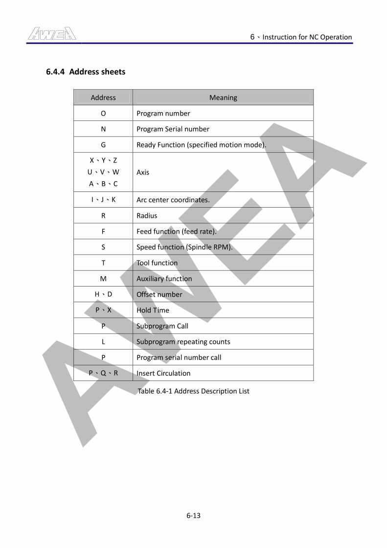
AWEA 6、Instruction for NC Operation
6-13
6.4.4 Address sheets
Address Meaning
O Program number
N Program Serial number
G Ready Function (specified motion mode).
X、Y、Z
U、V、W
A、B、C
Axis
I、J、K Arc center coordinates.
R Radius
F Feed function (feed rate).
S Speed function (Spindle RPM).
T Tool function
M Auxiliary function
H、D Offset number
P、X Hold Time
P Subprogram Call
L Subprogram repeating counts
P Program serial number call
P、Q、R Insert Circulation
Table 6.4-1 Address Description List
AWEA 6、Instruction for NC Operation
6-14
6.5 Program Edit
6.5.1 Program Search
1. In the Program Edit Mode, press the function key 【PROG】.
2. Press the program list softkey 【DIR】.
3. Confirm the program number, and then enter (the program number to search).
4. Press softkey 【O Retrieval】 at the bottom of monitor.
Remark:
(1) If the subprogram number can not be found, the alarm would be generated (No
specified no.).
6.5.2 Program Adding
1. In the Program Edit Mode, press the function key 【PROG】.
2. Press the program list softkey【DIR】。
3. Confirm the program number which for new adding, and then enter Address O (a new
program number).
4. Press the Insert key【INSERT】.
Remark:
(1) If the new program number is repeated, the alarm would be generated (selected
program no.).
6.5.3 Program Deletion
1. In the Program Edit Mode, press the function key 【PROG】.
2. Methods to delete a program are described as the following three groups:
(1) To delete a single program
Enter the address O (the program number to delete), and then perform the
motion three.
(2) Delete all programs
After entered the Address O (-9999), Press the third action.
(3) To delete the program within the specified range.
After entered the Address O (the first program number which for deleting), press
the third action.

AWEA 6、Instruction for NC Operation
6-15
3. Press the delete key 【DELETE】, and then the specified program is deleted.
Remark:
(1) Confirm if the program to delete is correct to avoid any loss of programs.
6.5.4 Command Address Searching
To look for command addresses, you can move the cursor or use the search mode.
1. Operation methods to move the cursor
(1) Press the cursor movement keys 【→】, and then the cursor will move backward
according to the number of times pressed.
(2) Press the cursor movement keys 【←】, and then the cursor will move forward
according to the number of times pressed.
(3) Press the cursor movement keys 【↑】, the cursor will be moved to the previous
signal block, and stop in the beginning of signal block.
(4) Press the cursor movement keys 【↑】, the cursor will be moved to the next
signal block, and stop in the beginning of signal block.
(5) Press the flip key 【PAGE↑】, the cursor will move to previous page, and stop in
the beginning of First signal block at every page.
(6) Press the flip key 【PAGE↓】, the cursor will move to next page, and stop in the
beginning of First signal block at every page
2. Operation:
(1) Input (To find the command address).
(2) Press the softkey 【SEARCH↓】 at bottom of monitor to search downwards, or
press the softkey 【SEARCH↑】 at bottom of monitor to search upwards.
Remark:
(1) The 0 in the command address can not be omitted. For example: To find M03, can
not just enter M3.
(2) Command address to be full input. For example: To find S300, CAN NOT enter the
S3 or S30.
(3) If it CAN NOT search the specified address, the (without searching data) alarm
will be occurred.
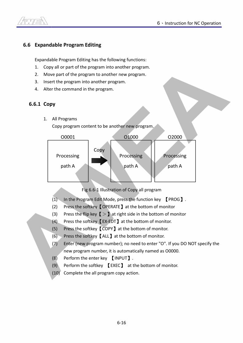
AWEA 6、Instruction for NC Operation
6-16
6.6 Expandable Program Editing
Expandable Program Editing has the following functions:
1. Copy all or part of the program into another program.
2. Move part of the program to another new program.
3. Insert the program into another program.
4. Alter the command in the program.
6.6.1 Copy
1. All Programs
Copy program content to be another new program.
O0001
Processing
path A
O1000
Processing
path A
O2000
Processing
path A
Copy
Fig 6.6-1 Illustration of Copy all program
(1) In the Program Edit Mode, press the function key 【PROG】.
(2) Press the softkey【OPERATE】at the bottom of monitor
(3) Press the flip key【>】at right side in the bottom of monitor
(4) Press the softkey【EX-EDT】at the bottom of monitor.
(5) Press the softkey【COPY】at the bottom of monitor.
(6) Press the softkey【ALL】at the bottom of monitor.
(7) Enter (new program number); no need to enter "O". If you DO NOT specify the
new program number, it is automatically named as O0000.
(8) Perform the enter key 【INPUT】.
(9) Perform the softkey 【EXEC】 at the bottom of monitor.
(10) Complete the all program copy action.
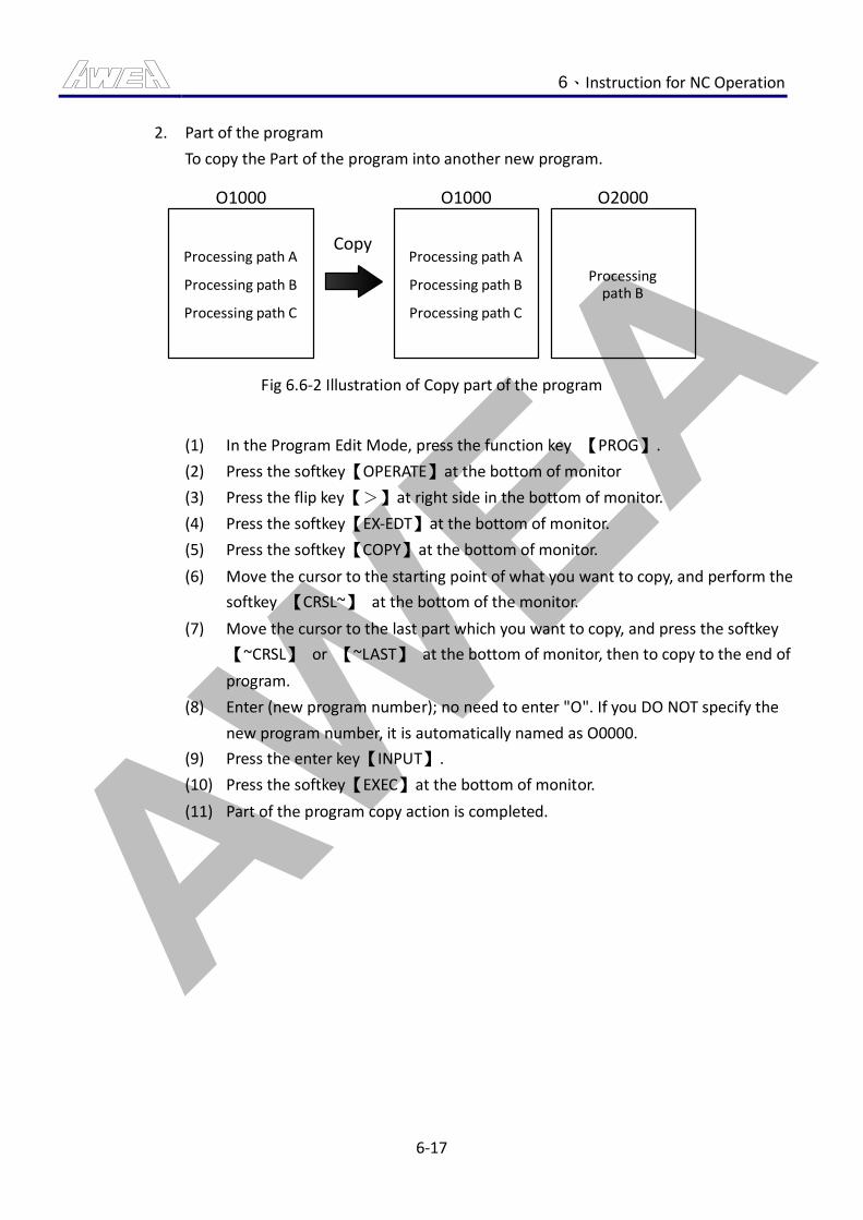
AWEA 6、Instruction for NC Operation
6-17
2. Part of the program
To copy the Part of the program into another new program.
O1000
Processing path A
O1000 O2000
Copy
Processing path B
Processing path C
Processing path A
Processing path B
Processing path C
Processingpath B
Fig 6.6-2 Illustration of Copy part of the program
(1) In the Program Edit Mode, press the function key 【PROG】.
(2) Press the softkey【OPERATE】at the bottom of monitor
(3) Press the flip key【>】at right side in the bottom of monitor.
(4) Press the softkey【EX-EDT】at the bottom of monitor.
(5) Press the softkey【COPY】at the bottom of monitor.
(6) Move the cursor to the starting point of what you want to copy, and perform the
softkey 【CRSL~】 at the bottom of the monitor.
(7) Move the cursor to the last part which you want to copy, and press the softkey
【~CRSL】 or 【~LAST】 at the bottom of monitor, then to copy to the end of
program.
(8) Enter (new program number); no need to enter "O". If you DO NOT specify the
new program number, it is automatically named as O0000.
(9) Press the enter key【INPUT】.
(10) Press the softkey【EXEC】at the bottom of monitor.
(11) Part of the program copy action is completed.
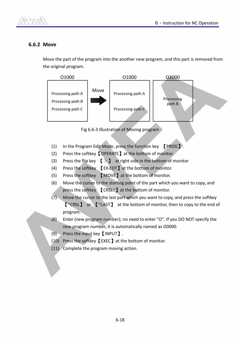
AWEA 6、Instruction for NC Operation
6-18
6.6.2 Move
Move the part of the program into the another new program, and this part is removed from
the original program.
O1000
Processing path A
O1000 O2000
Move
Processing path B
Processing path C
Processing path A
Processing path C
Processingpath B
Fig 6.6-3 Illustration of Moving program
(1) In the Program Edit Mode, press the function key 【PROG】.
(2) Press the softkey【OPERATE】at the bottom of monitor.
(3) Press the flip key 【>】 at right side in the bottom of monitor
(4) Press the softkey 【EX-EDT】at the bottom of monitor.
(5) Press the softkey 【MOVE】at the bottom of monitor.
(6) Move the cursor to the starting point of the part which you want to copy, and
press the softkey 【CRSL~】at the bottom of monitor.
(7) Move the cursor to the last part which you want to copy, and press the softkey
【~CRSL】 or 【~LAST】 at the bottom of monitor, then to copy to the end of
program.
(8) Enter (new program number); no need to enter "O". If you DO NOT specify the
new program number, it is automatically named as O0000.
(9) Press the input key【INPUT】.
(10) Press the softkey【EXEC】at the bottom of monitor.
(11) Complete the program moving action.
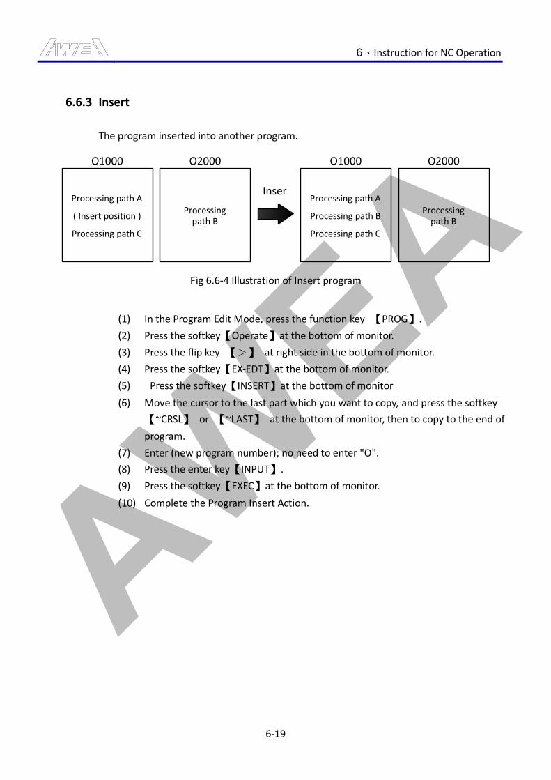
AWEA 6、Instruction for NC Operation
6-19
6.6.3 Insert
The program inserted into another program.
O2000 O1000 O2000
Inser
Processingpath B
Processing path A
Processing path C
Processingpath B
O1000
Processing path A
Processing path C
Processing path B( Insert position )
Fig 6.6-4 Illustration of Insert program
(1) In the Program Edit Mode, press the function key 【PROG】.
(2) Press the softkey【Operate】at the bottom of monitor.
(3) Press the flip key 【>】 at right side in the bottom of monitor.
(4) Press the softkey【EX-EDT】at the bottom of monitor.
(5) Press the softkey【INSERT】at the bottom of monitor
(6) Move the cursor to the last part which you want to copy, and press the softkey
【~CRSL】 or 【~LAST】 at the bottom of monitor, then to copy to the end of
program.
(7) Enter (new program number); no need to enter "O".
(8) Press the enter key【INPUT】.
(9) Press the softkey【EXEC】at the bottom of monitor.
(10) Complete the Program Insert Action.
AWEA 6、Instruction for NC Operation
6-20
6.6.4 Alter
Alter the command in the program.
(1) In the Program Edit Mode, press the function key 【PROG】.
(2) Press the softkey【OPERATE】at the bottom of monitor.
(3) Press the flip key 【>】 at right side in the bottom of monitor.
(4) Press the softkey【EX-EDT】at the bottom of monitor.
(5) Press the softkey【ALTER】at the bottom of monitor.
(6) Enter (the address of the modified command); you can assign up to 15
characters.
(7) Press the softkey【BEFORE ALTER】at the bottom of monitor.
(8) Enter (new command address). You can specify up to 15 characters.
(9) Press the softkey【AFTER ALTER】at the bottom of monitor.
(10) Perform the softkey 【EXEC】 at the bottom of monitor, change all the command
address, or perform the softkey 【EX-SGL】 at the bottom of monitor to search
downwards in sequence and to change; or perform the softkey 【SKIP】 at the
bottom of monitor to search the command address but skip without
modification.
Remark:
(1) To search under the program, the complete command address must be entered.
AWEA 6、Instruction for NC Operation
6-21
6.7 Use Memory Card to Perform DNC Processing
For the program which needs large memory space and can not be stored in the memory of the
controller, you can use the DNC function for processing. DNC means processing can be made
while transmitting; the program can be run through the memory card or computer transmission
for processing. This section describes how to use the memory card to have DNC machining
operations.
6.7.1 Operation Method
Run subprogram M198 to call DNC processing program:
1. Memory card is installed in the PCMCIA interface (the slot at LCD left side).
2. Press the 【DNC】 button on the machine operation panel.
3. Operation mode switched to “EDIT” mode.
4. Press the function key【PROG】, and then press softkey【 > 】 several times until the
softkey【CARD】appears, ad then stop.
5. Find out the position number of the processing program file to perform in the memory
card rather than its file name.
6. After finding out the position number of the processing program file to perform, add
the Command M198 Pxxxx (xxxx represents the position number of files in the memory
card).
7. Switch operating mode to "AUTO", and the controller status column shows "MEM"
mode.
8. Press the 【CYCLE START】 button to start DNC processing through PCMCIA interface.
Set the DNC processing procedures directly:
1. Press 【DNC】 button on the mechanical operation panel.
2. Operation mode switched to “AUTO” mode, and the controller status bar displays
"RMT" mode.
3. Press the function key 【PROG】, and then press softkey【 > 】 several times until
softkey【CARD】appears, and then stop.
4. Then press 【OPRT】 softkey to show the 【DNC-ST】softkey.
5. Find out the position number of the processing program file to perform in the memory
card; if it is not on the screen, please use the page keys to switch pages until you find
the screen page of the program to perform.
AWEA 6、Instruction for NC Operation
6-22
6. After inputting the position number in the memory card, press 【DNC-ST】 to set DNC
processing program; check the program name on option "DNC FILE NAME:" on screen
to confirm if the name of the program is correct.
7. Press the button 【CYCLE START】, and you may perform the DNC processing of PCMCIA
interface.
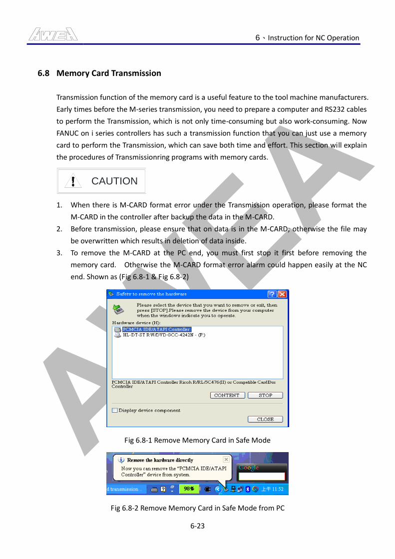
AWEA 6、Instruction for NC Operation
6-23
6.8 Memory Card Transmission
Transmission function of the memory card is a useful feature to the tool machine manufacturers.
Early times before the M-series transmission, you need to prepare a computer and RS232 cables
to perform the Transmission, which is not only time-consuming but also work-consuming. Now
FANUC on i series controllers has such a transmission function that you can just use a memory
card to perform the Transmission, which can save both time and effort. This section will explain
the procedures of Transmissionring programs with memory cards.
CAUTION
1. When there is M-CARD format error under the Transmission operation, please format the
M-CARD in the controller after backup the data in the M-CARD.
2. Before transmission, please ensure that on data is in the M-CARD; otherwise the file may
be overwritten which results in deletion of data inside.
3. To remove the M-CARD at the PC end, you must first stop it first before removing the
memory card. Otherwise the M-CARD format error alarm could happen easily at the NC
end. Shown as (Fig 6.8-1 & Fig 6.8-2)
Fig 6.8-1 Remove Memory Card in Safe Mode
Fig 6.8-2 Remove Memory Card in Safe Mode from PC
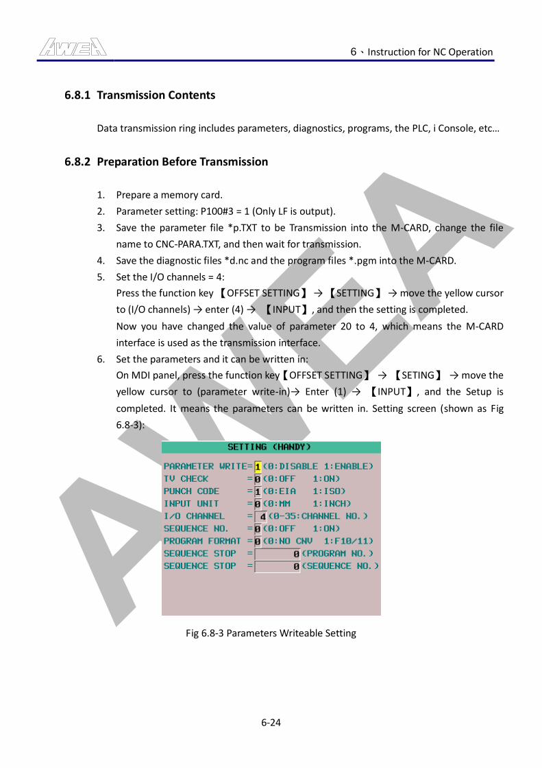
AWEA 6、Instruction for NC Operation
6-24
6.8.1 Transmission Contents
Data transmission ring includes parameters, diagnostics, programs, the PLC, i Console, etc…
6.8.2 Preparation Before Transmission
1. Prepare a memory card.
2. Parameter setting: P100#3 = 1 (Only LF is output).
3. Save the parameter file *p.TXT to be Transmission into the M-CARD, change the file
name to CNC-PARA.TXT, and then wait for transmission.
4. Save the diagnostic files *d.nc and the program files *.pgm into the M-CARD.
5. Set the I/O channels = 4:
Press the function key 【OFFSET SETTING】 → 【SETTING】 → move the yellow cursor
to (I/O channels) → enter (4) → 【INPUT】, and then the setting is completed.
Now you have changed the value of parameter 20 to 4, which means the M-CARD
interface is used as the transmission interface.
6. Set the parameters and it can be written in:
On MDI panel, press the function key【OFFSET SETTING】 → 【SETING】 → move the
yellow cursor to (parameter write-in)→ Enter (1) → 【INPUT】, and the Setup is
completed. It means the parameters can be written in. Setting screen (shown as Fig
6.8-3):
Fig 6.8-3 Parameters Writeable Setting
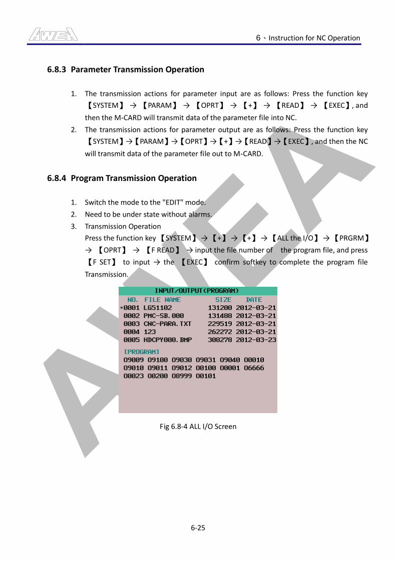
AWEA 6、Instruction for NC Operation
6-25
6.8.3 Parameter Transmission Operation
1. The transmission actions for parameter input are as follows: Press the function key
【SYSTEM】 → 【PARAM】 → 【OPRT】 → 【+】 → 【READ】 → 【EXEC】, and
then the M-CARD will transmit data of the parameter file into NC.
2. The transmission actions for parameter output are as follows: Press the function key
【SYSTEM】→【PARAM】→【OPRT】→【+】→【READ】→【EXEC】, and then the NC
will transmit data of the parameter file out to M-CARD.
6.8.4 Program Transmission Operation
1. Switch the mode to the "EDIT" mode.
2. Need to be under state without alarms.
3. Transmission Operation
Press the function key 【SYSTEM】 → 【+】 → 【+】 → 【ALL the I/O】 → 【PRGRM】
→ 【OPRT】 → 【F READ】 → input the file number of the program file, and press
【F SET】 to input → the 【EXEC】 confirm softkey to complete the program file
Transmission.
Fig 6.8-4 ALL I/O Screen
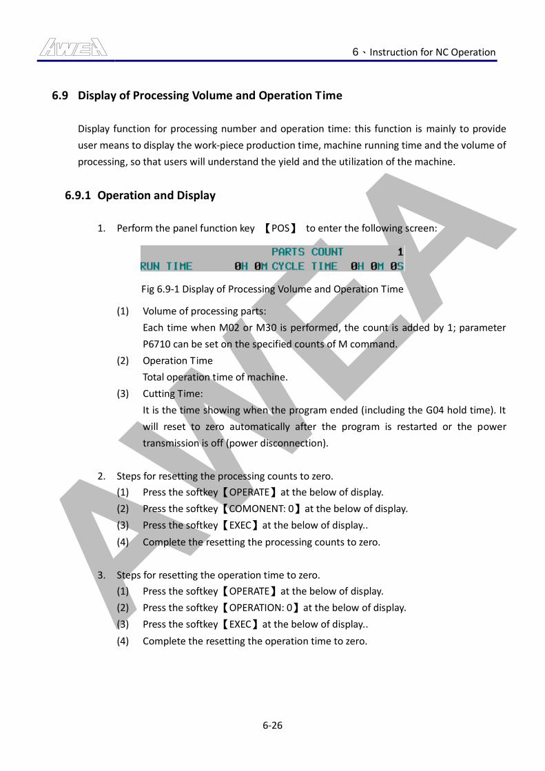
AWEA 6、Instruction for NC Operation
6-26
6.9 Display of Processing Volume and Operation Time
Display function for processing number and operation time: this function is mainly to provide
user means to display the work-piece production time, machine running time and the volume of
processing, so that users will understand the yield and the utilization of the machine.
6.9.1 Operation and Display
1. Perform the panel function key 【POS】 to enter the following screen:
Fig 6.9-1 Display of Processing Volume and Operation Time
(1) Volume of processing parts:
Each time when M02 or M30 is performed, the count is added by 1; parameter
P6710 can be set on the specified counts of M command.
(2) Operation Time
Total operation time of machine.
(3) Cutting Time:
It is the time showing when the program ended (including the G04 hold time). It
will reset to zero automatically after the program is restarted or the power
transmission is off (power disconnection).
2. Steps for resetting the processing counts to zero.
(1) Press the softkey【OPERATE】at the below of display.
(2) Press the softkey【COMONENT: 0】at the below of display.
(3) Press the softkey【EXEC】at the below of display..
(4) Complete the resetting the processing counts to zero.
3. Steps for resetting the operation time to zero.
(1) Press the softkey【OPERATE】at the below of display.
(2) Press the softkey【OPERATION: 0】at the below of display.
(3) Press the softkey【EXEC】at the below of display..
(4) Complete the resetting the operation time to zero.
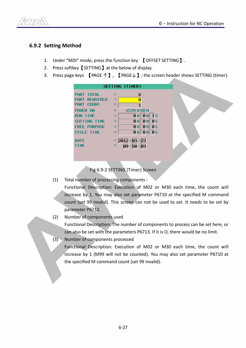
AWEA 6、Instruction for NC Operation
6-27
6.9.2 Setting Method
1. Under "MDI" mode, press the function key 【OFFSET SETTING】.
2. Press softkey【SETTING】at the below of display.
3. Press page keys 【PAGE ↑】, 【PAGE↓】; the screen header shows SETTING (timer).
Fig 6.9-2 SETTING (Timer) Screen
(1) Total number of processing components :
Functional Description: Execution of M02 or M30 each time, the count will
increase by 1. You may also set parameter P6710 at the specified M command
count (set 99 invalid). This screen can not be used to set. It needs to be set by
parameter P6712.
(2) Number of components used
Functional Description: The number of components to process can be set here, or
can also be set with the parameters P6713. If it is O, there would be no limit.
(3) Number of components processed
Functional Description: Execution of M02 or M30 each time, the count will
increase by 1 (M99 will not be counted). You may also set parameter P6710 at
the specified M command count (set 99 invalid).
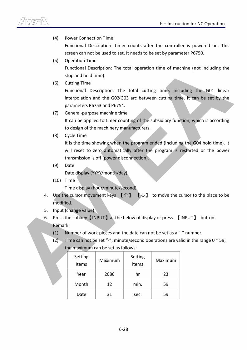
AWEA 6、Instruction for NC Operation
6-28
(4) Power Connection Time
Functional Description: timer counts after the controller is powered on. This
screen can not be used to set. It needs to be set by parameter P6750.
(5) Operation Time
Functional Description: The total operation time of machine (not including the
stop and hold time).
(6) Cutting Time
Functional Description: The total cutting time, including the G01 linear
interpolation and the G02/G03 arc between cutting time. It can be set by the
parameters P6753 and P6754.
(7) General-purpose machine time
It can be applied to timer counting of the subsidiary function, which is according
to design of the machinery manufacturers.
(8) Cycle Time
It is the time showing when the program ended (including the G04 hold time). It
will reset to zero automatically after the program is restarted or the power
transmission is off (power disconnection).
(9) Date
Date display (YYYY/month/day)
(10) Time
Time display (hour/minute/second).
4. Use the cursor movement keys 【↑】 【↓】 to move the cursor to the place to be
modified.
5. Input (change value).
6. Press the softkey【INPUT】at the below of display or press 【INPUT】 button.
Remark:
(1) Number of work-pieces and the date can not be set as a “-” number.
(2) Time can not be set “-”; minute/second operations are valid in the range 0 ~ 59;
the maximum can be set as follows:
Setting
Items Maximum
Setting
items Maximum
Year 2086 hr 23
Month 12 min. 59
Date 31 sec. 59
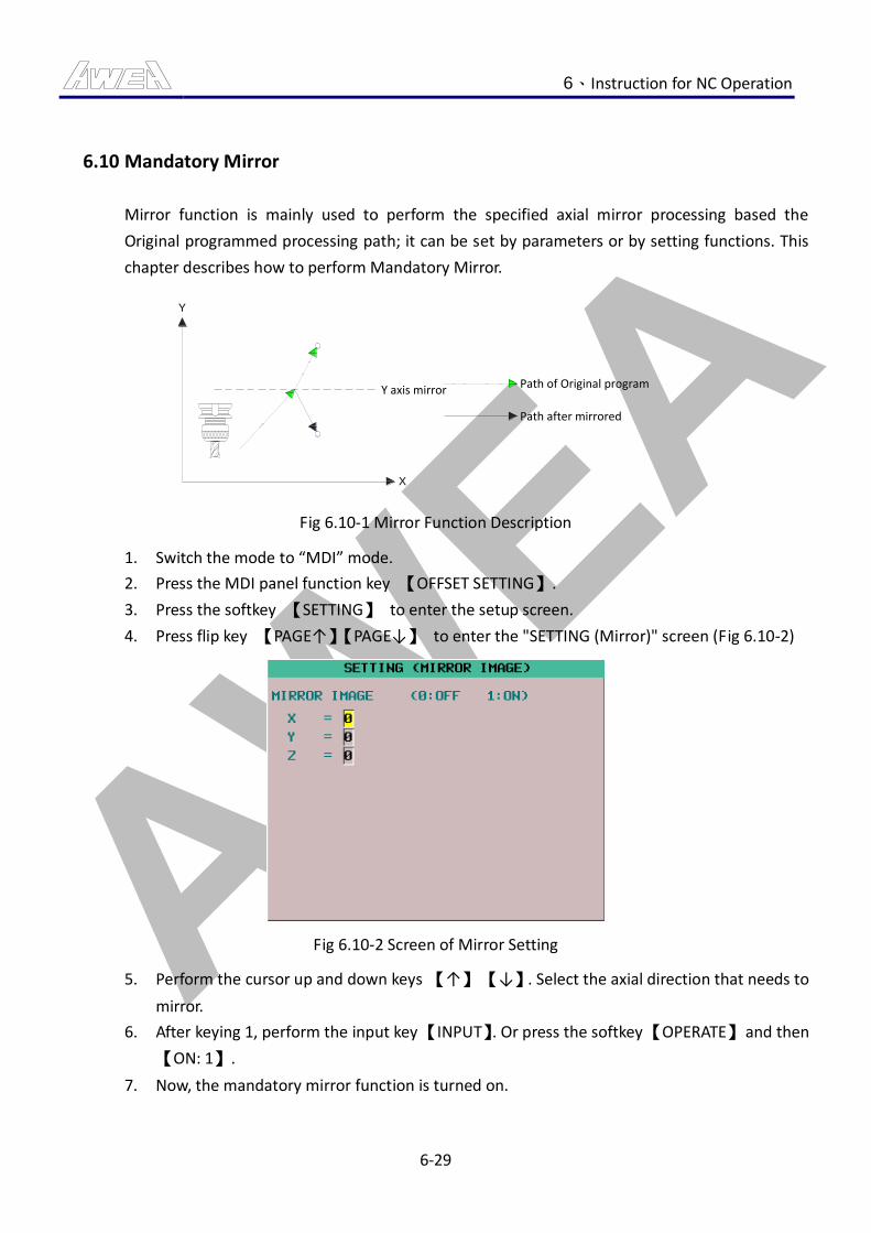
AWEA 6、Instruction for NC Operation
6-29
6.10 Mandatory Mirror
Mirror function is mainly used to perform the specified axial mirror processing based the
Original programmed processing path; it can be set by parameters or by setting functions. This
chapter describes how to perform Mandatory Mirror.
X
Y
Y axis mirror Path of Original program
Path after mirrored
Fig 6.10-1 Mirror Function Description
1. Switch the mode to “MDI” mode.
2. Press the MDI panel function key 【OFFSET SETTING】.
3. Press the softkey 【SETTING】 to enter the setup screen.
4. Press flip key 【PAGE↑】【PAGE↓】 to enter the "SETTING (Mirror)" screen (Fig 6.10-2)
Fig 6.10-2 Screen of Mirror Setting
5. Perform the cursor up and down keys 【↑】 【↓】. Select the axial direction that needs to
mirror.
6. After keying 1, perform the input key 【INPUT】. Or press the softkey 【OPERATE】 and then
【ON: 1】.
7. Now, the mandatory mirror function is turned on.

AWEA 7、Command Instruction
7-1
7. Command Instruction
7.1 Instruction of Each Description
This section is mainly for the introduction of each command, as well as the description of using
methods, which makes the operator to understand the use of each command more easily.
7.1.1 G Command
1. Command Description:
G function, also named as the ready function is the function designed for the control
system; each different G code represents a different meaning and motion.
G codes can be divided into two types:
(1) Single Block G Code: these G codes are only valid in the signal block where the
command locate and not valid in Single Blocks.
E.g.: G04, G09, G28... etc.
(2) Lasting G-code: these G code commands stay valid until replaced by another G
code from the same group.(For Group categories, please refer to the list of G
models)
E.g.:
G00 Z30.; (G00 valid signal block)
:
:
X20. Y20.; (G00 valid signal block)
G01 Z-5. F200; (G01 replace G00)
2. Remark:
(1) In the list of G function, G codes in the "00 Group" are signal block codes; G
codes other than the "00 Group" are the lasting codes.
(2) If more than one G codes of the same group are used in the same signal block,
the last G code is valid.
E.g.: G00 G01, X_Y_; (G00, G01, are the "00 Group" G code, in this section, G01 is
the valid one)
AWEA 7、Command Instruction
7-2
7.1.2 F Command
1. Command Description:
F functions, also known as the feeding function, are used to control moving speed of
the cutting tools.
Value after the command means:
Feed rate per minute: mm/min (metrics) and inch/min (imperial units)
Feed rate per turn: mm/rev (metrics) ince/rev (Imperial)
E.g.:
G91G01X0F1000; (feed rate 1000mm/min)
:
:
X20. Y20.; (feed rate 1000mm/min)
G01 Z-5. F200; (feed rate 1000mm/min 200 mm/min)
If the F function value exceeds the range of the mechanical design, it will take the
maximum feed rate of the designed setting as the real feed rate.
After setting the F function, the previously specified feed rate keeps valid if it is not
re-specified. For needs of the actual conditions when processing, "feed rate
percentage" knob on the mechanical operation panel can also be used to adjust the
actual feed rate.
AWEA 7、Command Instruction
7-3
7.1.3 M Command
1. Command Description:
M function is called as auxiliary function and used in two ways:
(1) By the motion requirement of the machinery, different M command are designed
to control different on/off motion and continuous motion.
(2) Contacts are reserved for connection with other accessories.
In addition to some general standard codes, if two or more M functions appear in the
same signal block, their motions DO NOT conflict through, the last M function is the
valid one.
E.g.:
S800 M03 M08; Now M08 is valid, M03 is invalid
AWEA 7、Command Instruction
7-4
7.1.4 S Command
1. Command Description:
S function, also named as Spindle RPM; the speed can be specified by the value after
the S command (in RPM).
If the S function value exceeds or lower than the range of the mechanical design, it will
take the maximum on minimum feed rate of the designed setting as the real feed rate.
For needs of the actual conditions when processing, "Spindle RPM percentage" Knob
on the mechanical operation panel can also be used to adjust the actual RPM.
When S command is performed, the spindle will not be operated. Only when the
Spindle CW (M03) or CCW (M04) command is selected, the spindle begins to run.
E.g.:
M3 S1000; (Spindle CW 1000RPM)
S200; (Spindle CW slow down to 200RPM)
:
:
M4 S200; (Spindle CCW 200RPM)
2. Remark:
(1) If the spindle has high/low gears, there may be the gear-change motions on
running S commands.
AWEA 7、Command Instruction
7-5
7.1.5 T Command
1. Command Description:
T function, also named as tool function.
The value after T command means the tool no. to call. When T command is performed,
the called tool is moved to the position and gets ready to be used; but there is no real
tool change motion yet.
2. Remark:
(1) If there are several different T commands in the same signal block, the Tool No.
of the last T command is valid.
E.g.:
T01 T02;T02 command is valid
AWEA 7、Command Instruction
7-6
7.2 M Command List
CAUTION
For CE specifications and operations to pre-run the command, the safety door must be under
the closed state. The Mode Enable Key Switch must be switched to auto mode to perform
operations of the command. Any incorrect operating procedure will generate an alarm to
inform the operator.
Type Description:
A: It means the M command can only starts after the move command within the same signal
block have been performed.
B: It means the M command and the move command within the same signal block run
concurrently.
Type M
Command Function Description Remark
0 Program Hold
1 OPT. STP(M01)
2 Program End
B 3 Spindle Clockwise (CW)
B 4 Spindle Clockwise (CW)
A 5 Spindle Stop
A 6 Auto Tool Change M6 Macro O9001
B 8 Coolant Start
A 9 Coolant and air blow stop.
B 13 Spindle CW and coolant start.
B 14 Spindle CCW and coolant start
A 19 Spindle Positioning
21 ATC arm moves to the spindle
side M6,M73,I/O by pass
22 ARM downward M6,M73,I/O by pass
AWEA 7、Command Instruction
7-7
Type M
Command Function Description Remark
23 ARM CW M6,M73,I/O by pass
24 ARM CCW M6,M73,I/O by pass
25 ARM upward M6,M73,I/O by pass
26 ATC arm moves to the middle
side M6,M73,I/O by pass
27 Arm moves MAZ side M6,M73,I/O by pass
B 28 Coolant Through Tool @OIL/T
29 Rigid Tapping
30 Auto Disconnection
B 35
Tool change door opened and
measuring head stretched
out.
@M137
A 36
Tool change door closed and
measuring head stretched
back.
@M137
41 Vertical Spindle Tool Unclamp M6,M73,I/O by pass
42 Vertical Spindle Tool Grab M6,M73,I/O by pass
B 48 Feed rate override is valid
B 49 Feed rate override is invalid
B 51 Coolant Through Spindle @CTS
B 63 Chip Screw Start
A 64 Chip Screw Stop
69 Auto Tool Change ended M06 Macro
70 Vertical Auto Tool Change
ended M06 Macro O9001
B 79 Air Blow Through Spindle
Start. OPTION @SPAIR
B 80 M80: Air Blow Through
Spindle Stop. OPTION @SPAIR
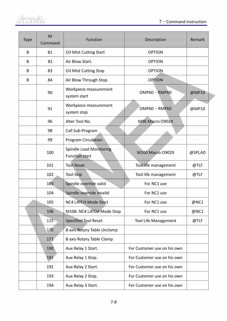
AWEA 7、Command Instruction
7-8
Type M
Command Function Description Remark
B 81 Oil Mist Cutting Start OPTION
B 82 Air Blow Start. OPTION
B 83 Oil Mist Cutting Stop OPTION
B 84 Air Blow Through Stop. OPTION
90 Workpiece measurement
system start OMP60、RMP60 @MP10
91 Workpiece measurement
system stop OMP60、RMP60 @MP10
96 Alter Tool No. M96 Macro O9024
98 Call Sub-Program
99 Program Circulation
100 Spindle Load Monitoring
Function start M100 Macro O9029 @SPLAD
101 Tool Reset Tool life management @TLF
102 Tool Skip Tool life management @TLF
103 Spindle override valid For NC1 use
104 Spindle override invalid For NC1 use
105 NC4 LATCH Mode Start For NC1 use @NC1
106 M106: NC4 LATCH Mode Stop For NC1 use @NC1
115 Specified Tool Reset Tool Life Management @TLF
170 B axis Rotary Table Unclamp
171 B axis Rotary Table Clamp
190 Aux Relay 1 Start. For Customer use on his own
191 Aux Relay 1 Stop. For Customer use on his own
192 Aux Relay 2 Start. For Customer use on his own
193 Aux Relay 2 Stop. For Customer use on his own
194 Aux Relay 3 Start. For Customer use on his own

AWEA 7、Command Instruction
7-9
Type M
Command Function Description Remark
195 Aux Relay 3 Stop For Customer use on his own
196 Aux Relay 4 Start For Customer use on his own
197 Aux Relay 4 Stop For Customer use on his own
Table 7.2-1 M Command List
AWEA 7、Command Instruction
7-10
7.3 M Command Format Description
7.3.1 M00 Program Stop
1. Command Description:
Under the automatic execution of programs, when the "M00" command is performed,
the controller will stop the machine's all processing command motions, and the 【FEED
HOLD】 button would be lighting. To continue performing the follow-up program, click
【CYCLE START】 button and then you can continue to perform the following program
sections.
2. Application Examples:
O0001:
…
G91G1X20.Y20.F100M00; → Only after the execution of G command is complete, the
program will stop.
…
M00; Program Stop.
…
M30;
AWEA 7、Command Instruction
7-11
7.3.2 M01 Optional Stop
1. Command Description:
The function of this command is the same as M00; the difference is that the operator
can use 【OPT. STP】 button on panel to select the program to stop or non-stop.
2. Operation Method:
(1) After the 【OPT. STP】 button is pressed, the indicator lights. The function is valid
when and the program is performed to M01, and the 【HOLD FEEDING】 button
indicator will light up after the program to perform is stopped; if 【CYCLE START】
button is pressed again, the following processing program can be performed
again.
(2) Under execution of M01, if the 【OPT. STP】 button is canceled, the function
would be still valid, and the 【CYCLE START】 button can be pressed to continue
on performing the following processing program.
(3) If the 【OPT. STP】 button is not pressed, the command is invalid (program does
not stop) even when the program is run to M01.
3. Application Examples:
O0001;
…
G91G1X20.Y20.F100M01; →When the button is in the active state, the program stops
after G command performed.
…
M01; → The program stops when the button is on.
…
M30;
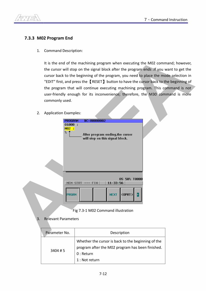
AWEA 7、Command Instruction
7-12
7.3.3 M02 Program End
1. Command Description:
It is the end of the machining program when executing the M02 command; however,
the cursor will stop on the signal block after the program ends .If you want to get the
cursor back to the beginning of the program, you need to place the mode selection in
“EDIT” first, and press the 【RESET】 button to have the cursor back to the beginning of
the program that will continue executing machining program. This command is not
user-friendly enough for its inconvenience; therefore, the M30 command is more
commonly used.
2. Application Examples:
Fig 7.3-1 M02 Command illustration
3. Relevant Parameters
Parameter No. Description
3404 # 5
Whether the cursor is back to the beginning of the
program after the M02 program has been finished.
0 : Return
1 : Not return

AWEA 7、Command Instruction
7-13
7.3.4 M03 / M04 / M05 Spindle CW / CCW / Stop
1. Command Description:
(1) M03/M04 commands need to work with the S command, and can be assigned to
every single section.
(2) Spindle will not be turning if booting the system without executing the S
command (initial speed default value = 0); otherwise, the spindle is turning at the
final setting of speed after the system has been operated without the S
command.
(3) M03/M04 can be used together with G code and coordinate commands in one
single section.
2. The following commands and operations can cancel the M03/M04 status.
Command:
(1) M02: Program end command
(2) M05: Spindle Stop Command
(3) M19: Spindle Positioning Command
(4) M29: Rigid Tapping Command
(5) M30: Program End and Restore
Operation:
(1) Press Reset Button.
(2) Press Spindle Stop Button
(3) Press Spindle Positioning Button
(4) Press Emergency Stop Button
3. Application Examples:
O0001;
…
M03 S1000;→ Spindle CW 1000rpm.
…
M5;→ Spindle Stop
…
M04 S1000;→ Spindle CCW 1000rpm.
…
M30;
AWEA 7、Command Instruction
7-14
7.3.5 M06 Tool Exchange
1. Command Description:
Exchange a specified tool to the spindle for application.
2. Command Format:
M06 Tt; →Tt 【REFERENCE NUMBER OF TOOL EXCHANGE】
M06 T0; → Tool Returning Command
The T command must be added while executing the M06 command; otherwise, you
will be alerted by alarm.
3. Application Examples:
It is assumed that the spindle Tool no. is 10.
O0001:
…
M06 T2;→The spindle tool is changed to No. 2.
…
M06 T2; → No Tool Change.
…
M30;
AWEA 7、Command Instruction
7-15
7.3.6 M08 / M09 Coolant Start / Stop
1. Command Description:
Both machining air blast and coolant are capable of cooling tools and workpieces,
cleaning chips and lubricating to extend tool life.
2. Command Format:
M08: Coolant is starting.
M09: Air blow/Coolant stop.
3. Application Examples:
O0001;
…
M08; → Coolant Start.
…
M09; → Coolant Stop.
…
M30;
AWEA 7、Command Instruction
7-16
7.3.7 M13 / M14 Spindle CW / CCW and Coolant Start
1. Command Description:
The function of spindle rotation and coolant can be initiated simultaneously to simplify
the application of commands.
2. Command Format:
M13: Spindle CW and Coolant Start.
M14: Spindle CCW and Coolant Start.
AWEA 7、Command Instruction
7-17
7.3.8 M19 Spindle Positioning
1. Command Description:
The spindle stops after being rotated to a fixed angular position, generally applied to
the situation that the positioning of Precision Boring and Back Boring of the system
must be done (such as M06 automatic change of tools); meanwhile, this command
must be manually performed first (under “MDI” mode) for the adjustment of offset
direction while running G76 or G87 command.
2. Command Format:
M19: Spindle Positioning.
AWEA 7、Command Instruction
7-18
7.3.9 M28 Coolant Through Tool Start (Optional)
1. Command Description:
Coolant through tool, same with the Coolant function, both have the function that to
cool the tool and workpiece, clear the metal chips and lubricate, and prolong the tool
life function.
2. Command Format:
M28: Coolant Through Tool Start
M09: Coolant Through Tool Stop
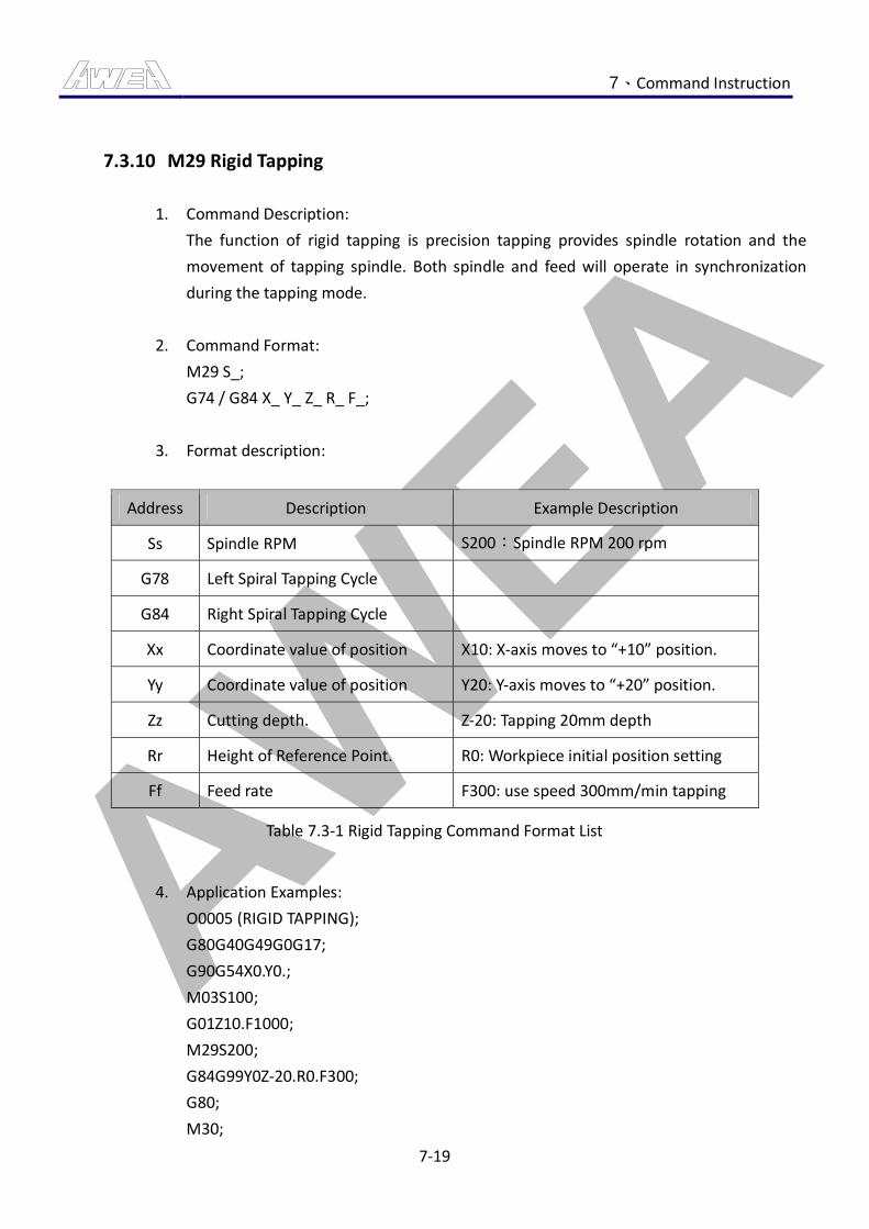
AWEA 7、Command Instruction
7-19
7.3.10 M29 Rigid Tapping
1. Command Description:
The function of rigid tapping is precision tapping provides spindle rotation and the
movement of tapping spindle. Both spindle and feed will operate in synchronization
during the tapping mode.
2. Command Format:
M29 S_;
G74 / G84 X_ Y_ Z_ R_ F_;
3. Format description:
Address Description Example Description
Ss Spindle RPM S200:Spindle RPM 200 rpm
G78 Left Spiral Tapping Cycle
G84 Right Spiral Tapping Cycle
Xx Coordinate value of position X10: X-axis moves to “+10” position.
Yy Coordinate value of position Y20: Y-axis moves to “+20” position.
Zz Cutting depth. Z-20: Tapping 20mm depth
Rr Height of Reference Point. R0: Workpiece initial position setting
Ff Feed rate F300: use speed 300mm/min tapping
Table 7.3-1 Rigid Tapping Command Format List
4. Application Examples:
O0005 (RIGID TAPPING);
G80G40G49G0G17;
G90G54X0.Y0.;
M03S100;
G01Z10.F1000;
M29S200;
G84G99Y0Z-20.R0.F300;
G80;
M30;

AWEA 7、Command Instruction
7-20
7.3.11 M30 Program End and Restore
1. Command Description:
M30: A warning light and cursor “_” will automatically get back to the beginning of the
program after the machining program is finished and the execution is ended. Moreover,
all motions stop and CNC returns to initial status, valid together with automatic power
off.
2. Command Format:
M30: Response after Program End; or automatic power off is initiated.
AWEA 7、Command Instruction
7-21
7.3.12 M51 Coolant Through Spindle (Optional)
1. Command Description:
Coolant through spindle and coolant through tool have the same functions. And they
are all effective for cooling the tools and workpieces, cleaning chips and lubricating,
and may extend the tool life. The difference is the position of outlet. For the function of
coolant through spindle, it certainly drains coolant from the center of the spindle, but
necessarily in collaboration with tools for coolant through spindle for applications. As
for the function of coolant through tool, it drains coolant from the side of the spindle in
collaboration with all types of tools. But strictly, thanks to the coolant through spindle
are located at the highest point of tools, it will make better cooling effect than the
coolant through tool and with an extend tool life.
2. Command Format:
M51: Coolant Through Spindle Start
M09: Coolant Through Spindle Stop
AWEA 7、Command Instruction
7-22
7.3.13 M63 / M64 Chip Screw Start / Stop
1. Command Description:
The machining process will produce iron chips that chip cleaning device sweeps away
iron chips to keep the machine table clean, and avoid component damage or
machining malfunction. The command is applied to the machining process for running
the chip cleaning device.
2. Command Format:
M63: Chip Conveyor Start
M64: Chip Conveyor Stop
AWEA 7、Command Instruction
7-23
7.3.14 M79 / M80 Air Blow Through Spindle Start / Stop (Optional)
1. Command Description:
Air Blow Through Spindle and Coolant have the same function. They are all effective for
cooling the tools and workpieces, cleaning chips and lubricating, and may extend the
tool life.
2. Command Format:
M79: Air Blow Through Spindle Start.
M80: Air Blow Through Spindle Stop.
M09: Air blow/Coolant/Air Blow Through Spindle Stop.
AWEA 7、Command Instruction
7-24
7.3.15 M81 / M83 Oil Mist Cutting Start / Stop (Optional)
1. Command Description:
Oil Mist Cutting has the same function with Air Blow Processing and Coolant. They are
all effective for cooling the tools and workpieces, cleaning chips and lubricating, and
may extend the tool life.
2. Command Format:
M81: Oil Mist Cutting Start.
M83: Oil Mist Cutting Stop.

AWEA 7、Command Instruction
7-25
7.3.16 M82 / M84 Air Blow Start / Stop
1. Command Description:
Air Blow Processing and Coolant have the same function. They are all effective for
cooling the tools and workpieces, cleaning chips and lubricating, and may extend the
tool life
2. Command Format:
M82: Air Blow Start.
M84: Air Blow Stop.
M09: Air blow/Coolant Stop.

AWEA 7、Command Instruction
7-26
7.3.17 M90 / M91 Workpiece Measurement Start / Stop (Optional)
1. Command Description:
Only when the optional product workpiece measurement system is purchased, may
this command be valid. This command is used to start and stop the workpiece
measurement system, and it may automatically switch on and off with the program.
2. Command Format:
M90: Workpiece Measurement Start.
M91: Workpiece Measurement Stop.
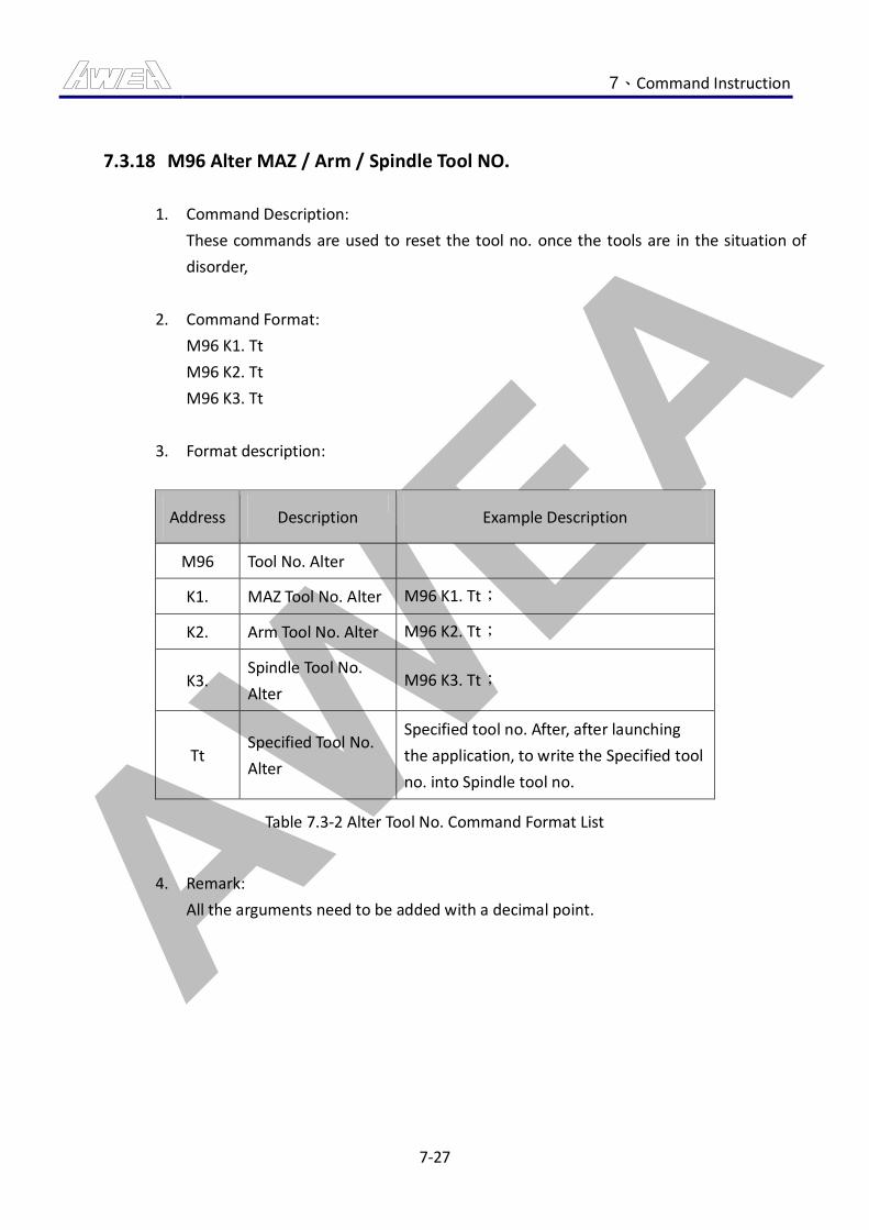
AWEA 7、Command Instruction
7-27
7.3.18 M96 Alter MAZ / Arm / Spindle Tool NO.
1. Command Description:
These commands are used to reset the tool no. once the tools are in the situation of
disorder,
2. Command Format:
M96 K1. Tt
M96 K2. Tt
M96 K3. Tt
3. Format description:
Address Description Example Description
M96 Tool No. Alter
K1. MAZ Tool No. Alter M96 K1. Tt;
K2. Arm Tool No. Alter M96 K2. Tt;
K3. Spindle Tool No.
Alter M96 K3. Tt;
Tt Specified Tool No.
Alter
Specified tool no. After, after launching
the application, to write the Specified tool
no. into Spindle tool no.
Table 7.3-2 Alter Tool No. Command Format List
4. Remark:
All the arguments need to be added with a decimal point.
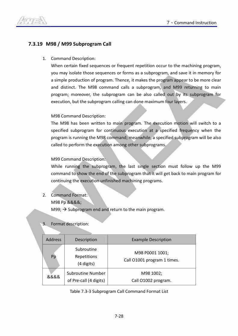
AWEA 7、Command Instruction
7-28
7.3.19 M98 / M99 Subprogram Call
1. Command Description:
When certain fixed sequences or frequent repetition occur to the machining program,
you may isolate those sequences or forms as a subprogram, and save it in memory for
a simple production of program. Thence, it makes the program appear to be more clear
and distinct. The M98 command calls a subprogram, and M99 returning to main
program; moreover, the subprogram can be also called out by its subprogram for
execution, but the subprogram calling can done maximum four layers.
M98 Command Description:
The M98 has been written to main program. The execution motion will switch to a
specified subprogram for continuous execution at a specified frequency when the
program is running the M98 command; meanwhile, a specified subprogram will be also
called to perform the execution among other subprograms.
M99 Command Description:
While running the subprogram, the last single section must follow up the M99
command to show the end of the subprogram that it will get back to main program for
continuing the execution unfinished machining programs.
2. Command Format:
M98 Pp &&&&;
M99; Subprogram end and return to the main program.
3. Format description:
Address Description Example Description
Pp
Subroutine
Repetitions
(4 digits)
M98 P0001 1001;
Call O1001 program 1 times.
&&&& Subroutine Number
of Pre-call (4 digits)
M98 1002;
Call O1002 program.
Table 7.3-3 Subprogram Call Command Format List
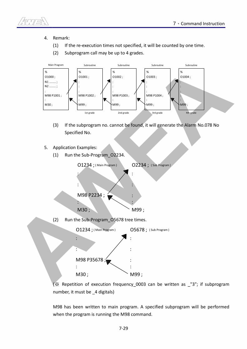
AWEA 7、Command Instruction
7-29
4. Remark:
(1) If the re-execution times not specified, it will be counted by one time.
(2) Subprogram call may be up to 4 grades.
M98 P1001 ;
Subroutine
%
Subroutine Subroutine Subroutine
1st grade 2nd grade 3rd grade 4th grade
:
M30 ;
O1001 ;
:
:
:M98 P1002 ;
:
M99 ;
%
O1002 ;
:
:
:M98 P1003 ;
:
M99 ;
%
O1003 ;
:
:
:M98 P1004 ;
:
M99 ;
%
O1004 ;
:
:
:
::
M99 ;
Main Program
%
O1000 ;
N1 ........ ;
N2 ........ ;
:
(3) If the subprogram no. cannot be found, it will generate the Alarm No.078 No
Specified No.
5. Application Examples:
(1) Run the Sub-Program_O2234.
( Main Program )O1234 ;
:
:
M98 P2234 ;
:
M30 ;
O2234 ;
:
:
::
M99 ;
( Sub Program )
(2) Run the Sub-Program_O5678 tree times.
( Main Program )O1234 ;
:
:
M98 P35678 ;
:
M30 ;
O5678 ;
:
:
::
M99 ;
( Sub Program )
(※ Repetition of execution frequency_0003 can be written as _"3"; if subprogram
number, it must be _4 digitals)
M98 has been written to main program. A specified subprogram will be performed
when the program is running the M98 command.
AWEA 7、Command Instruction
7-30
M99 must be specified separately, and written to the end of a subprogram. When the
program is running the M99 command, the subprogram will end up and get back to
main program that M98 will work on another machining program in next single
section.
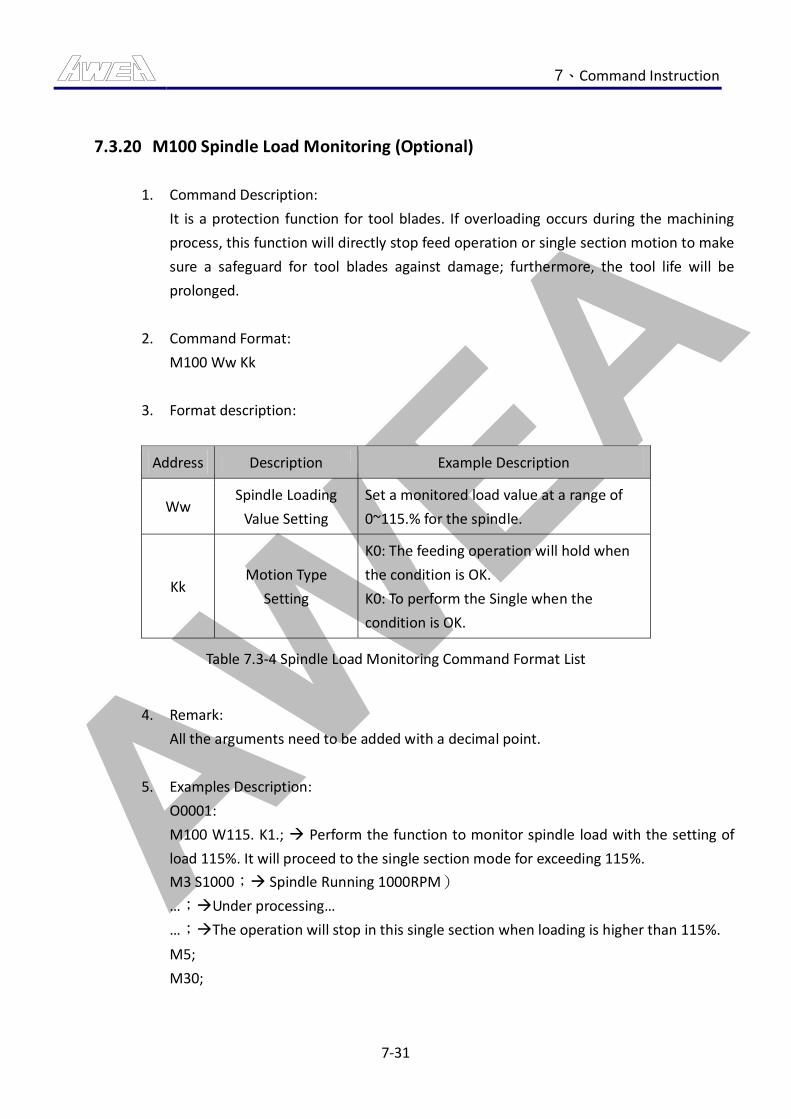
AWEA 7、Command Instruction
7-31
7.3.20 M100 Spindle Load Monitoring (Optional)
1. Command Description:
It is a protection function for tool blades. If overloading occurs during the machining
process, this function will directly stop feed operation or single section motion to make
sure a safeguard for tool blades against damage; furthermore, the tool life will be
prolonged.
2. Command Format:
M100 Ww Kk
3. Format description:
Address Description Example Description
Ww Spindle Loading
Value Setting
Set a monitored load value at a range of
0~115.% for the spindle.
Kk Motion Type
Setting
K0: The feeding operation will hold when
the condition is OK.
K0: To perform the Single when the
condition is OK.
Table 7.3-4 Spindle Load Monitoring Command Format List
4. Remark:
All the arguments need to be added with a decimal point.
5. Examples Description:
O0001:
M100 W115. K1.; Perform the function to monitor spindle load with the setting of
load 115%. It will proceed to the single section mode for exceeding 115%.
M3 S1000; Spindle Running 1000RPM)
…;Under processing…
…;The operation will stop in this single section when loading is higher than 115%.
M5;
M30;
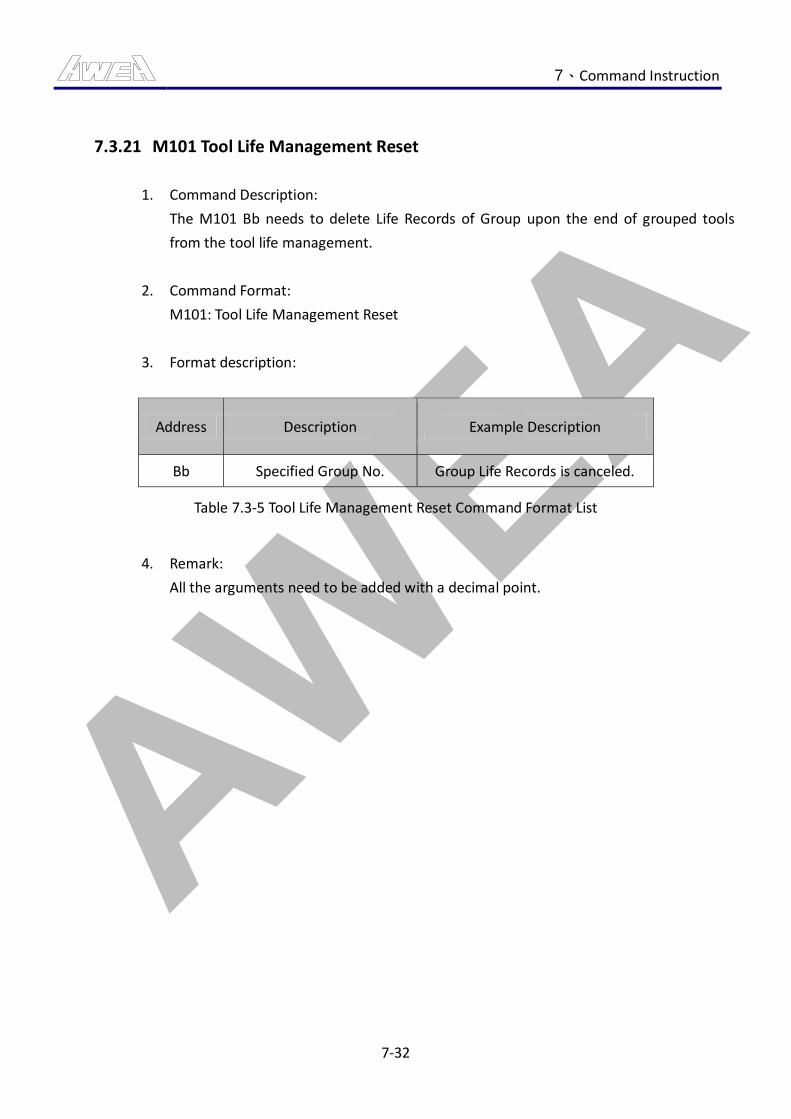
AWEA 7、Command Instruction
7-32
7.3.21 M101 Tool Life Management Reset
1. Command Description:
The M101 Bb needs to delete Life Records of Group upon the end of grouped tools
from the tool life management.
2. Command Format:
M101: Tool Life Management Reset
3. Format description:
Address Description Example Description
Bb Specified Group No. Group Life Records is canceled.
Table 7.3-5 Tool Life Management Reset Command Format List
4. Remark:
All the arguments need to be added with a decimal point.
AWEA 7、Command Instruction
7-33
7.3.22 M102 Tool Life Management’s TOOL SKIP
1. Command Description:
Currently, it is not the end of tool life but the reality is tool condition is too poor to
perform any jobs that M102 command is required to terminate the tool life
immediately.
2. Command Format:
M102: TOOL SKIP
AWEA 7、Command Instruction
7-34
7.3.23 M105 / M106 NC4 LATCH Mode Start / Stop(Optional)
1. Command Description:
Only when the optional product Renishaw NC4 is purchased, may this command be
valid. This command is used to start and stop the NC4 Measurement Mode, and it
may automatically switch on and off with the program.
2. Command Format:
M105: NC4 LATCH Mode Start
M106: NC4 LATCH Mode Stop
AWEA 7、Command Instruction
7-35
7.3.24 M170∕M171 B-Axis Rotary Table Unclamp / Clamp
1. Command Description:
This command applies to the operation of B-Axis valid with the command from B-Axis’s
rotary table unclamp/clamp mechanism.
2. Command format:
M170: B axis Rotary Table Unclamp
M171: B axis Rotary Table Clamp
3. Program Example:
O0001; (B AXIS TEST)
M170; B-Axis Rotary Table Unclamp.
G91 G28 B0.; B-Axis Home Return.
B90.; B-Axis rotated to 90 angle.
B180.; B-Axis rotated to 180 angle.
B270.; B-Axis rotated to 270 angle.
M171; B-Axis Rotary Table Clamp.
M30; Program End.
AWEA 7、Command Instruction
7-36
7.3.25 M190 / M191 Aux Relay 1 Start / Stop
1. Command Description:
User-friendly interfaces and commands for controlling peripheral devices are available
to customers that the device’s control loops can be connected to contacts on Auxiliary
Relay 1, which will be running control commands.
2. Command Format:
M190: Aux Relay 1 Start.
M191: Aux Relay 1 Stop.

AWEA 7、Command Instruction
7-37
7.3.26 M192 / M193 Aux Relay 2 Start / Stop
1. Command Description:
To provide customers easy control of interface and commands of peripheral equipment
so as to connect the control circuit of equipment to the contacts of Auxiliary Relay 2,
and use Auxiliary Relay 2 Command to control.
2. Command Format:
M192: Aux Relay 2 Start.
M191: Aux Relay 2 Stop.

AWEA 7、Command Instruction
7-38
7.3.27 M194 / M195 Aux Relay 3 Start / Stop
1. Command Description:
To provide customers easy control of interface and commands of peripheral equipment
so as to connect the control circuit of equipment to the contacts of Auxiliary Relay 3,
and use Auxiliary Relay 3 Command to control.
2. Command Format:
M194: Aux Relay 3 Start.
M195: Aux Relay 3 Stop.
AWEA 7、Command Instruction
7-39
7.3.28 M196 / M197 Aux Relay 4 Start / Stop
1. Command Description:
To provide customers easy control of interface and commands of peripheral equipment
so as to connect the control circuit of equipment to the contacts of Auxiliary Relay 4,
and use Auxiliary Relay 4 Command to control.
2. Command Format:
M196: Aux Relay 4 Start.
M197: Aux Relay 4 Stop.

AWEA 8、Function Description
8-1
8. Function Description
8.1 Machine Status Display Function
Status display provides the illustration function that mainly helps the machine operator make
sure whether current operating tool no., reServo tool no., tool magazine numbers, HEAD types
and angles o f HEADs are properly valid; accordingly, the machine operator will be able to
confirm the machine status based on the data he/she receives, to prevent from wrong status
occurrence and machine abnormality.
8.1.1 Spindle Tool NO. Display
Fig 8.1-1 Spindle Tool NO. Display Screen
1. SPD TOOL: It displays the operating tool no. on the spindle.
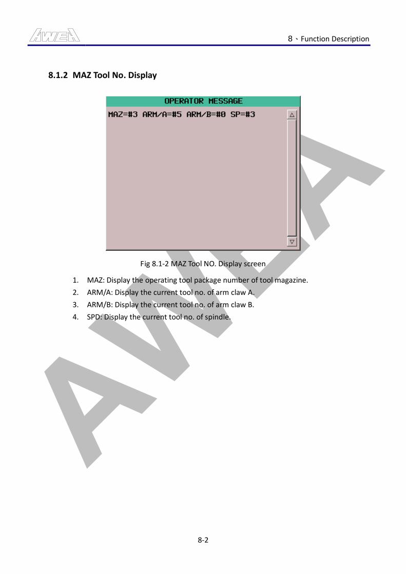
AWEA 8、Function Description
8-2
8.1.2 MAZ Tool No. Display
Fig 8.1-2 MAZ Tool NO. Display screen
1. MAZ: Display the operating tool package number of tool magazine.
2. ARM/A: Display the current tool no. of arm claw A.
3. ARM/B: Display the current tool no. of arm claw B.
4. SPD: Display the current tool no. of spindle.
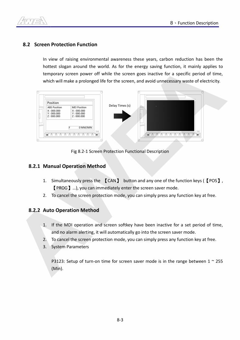
AWEA 8、Function Description
8-3
8.2 Screen Protection Function
In view of raising environmental awareness these years, carbon reduction has been the
hottest slogan around the world. As for the energy saving function, it mainly applies to
temporary screen power off while the screen goes inactive for a specific period of time,
which will make a prolonged life for the screen, and avoid unnecessary waste of electricity.
PositionABS PositionX : 000.000Y : 000.000Z : 000.000
MEI PositionX : 000.000Y : 000.000Z : 000.000
F 0 MM/MIN
Delay Times (s)
Fig 8.2-1 Screen Protection Functional Description
8.2.1 Manual Operation Method
1. Simultaneously press the 【CAN】 button and any one of the function keys (【POS】,
【PROG】…), you can immediately enter the screen saver mode.
2. To cancel the screen protection mode, you can simply press any function key at free.
8.2.2 Auto Operation Method
1. If the MDI operation and screen softkey have been inactive for a set period of time,
and no alarm alerting, it will automatically go into the screen saver mode.
2. To cancel the screen protection mode, you can simply press any function key at free.
3. System Parameters
P3123: Setup of turn-on time for screen saver mode is in the range between 1 ~ 255
(Min).
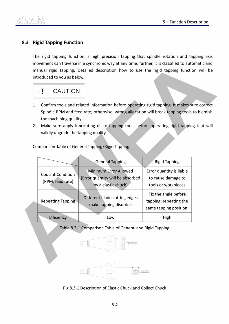
AWEA 8、Function Description
8-4
8.3 Rigid Tapping Function
The rigid tapping function is high precision tapping that spindle rotation and tapping axis
movement can traverse in a synchronic way at any time; further, it is classified to automatic and
manual rigid tapping. Detailed description how to use the rigid tapping function will be
introduced to you as below.
CAUTION
1. Confirm tools and related information before operating rigid tapping. It makes sure correct
Spindle RPM and feed rate; otherwise, wrong allocation will break tapping tools to blemish
the machining quality.
2. Make sure apply lubricating oil to tapping tools before operating rigid tapping that will
validly upgrade the tapping quality.
Comparison Table of General Tapping/Rigid Tapping
General Tapping Rigid Tapping
Coolant Condition
(RPM, feed rate)
Minimum Error Allowed
(Error quantity will be absorbed
by a elastic chuck)
Error quantity is liable
to cause damage to
tools or workpieces
Repeating Tapping Different blade cutting edges
make tapping disorder.
Fix the angle before
tapping, repeating the
same tapping position.
Efficiency Low High
Table 8.3-1 Comparison Table of General and Rigid Tapping
Fig 8.3-1 Description of Elastic Chuck and Collect Chuck
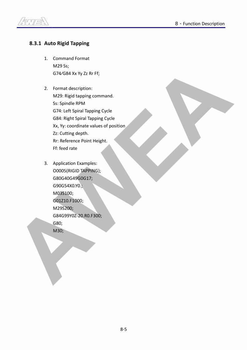
AWEA 8、Function Description
8-5
8.3.1 Auto Rigid Tapping
1. Command Format
M29 Ss;
G74∕G84 Xx Yy Zz Rr Ff;
2. Format description:
M29: Rigid tapping command.
Ss: Spindle RPM
G74: Left Spiral Tapping Cycle
G84: Right Spiral Tapping Cycle
Xx, Yy: coordinate values of position
Zz: Cutting depth.
Rr: Reference Point Height.
Ff: feed rate
3. Application Examples:
O0005(RIGID TAPPING);
G80G40G49G0G17;
G90G54X0.Y0.;
M03S100;
G01Z10.F1000;
M29S200;
G84G99Y0Z-20.R0.F300;
G80;
M30;
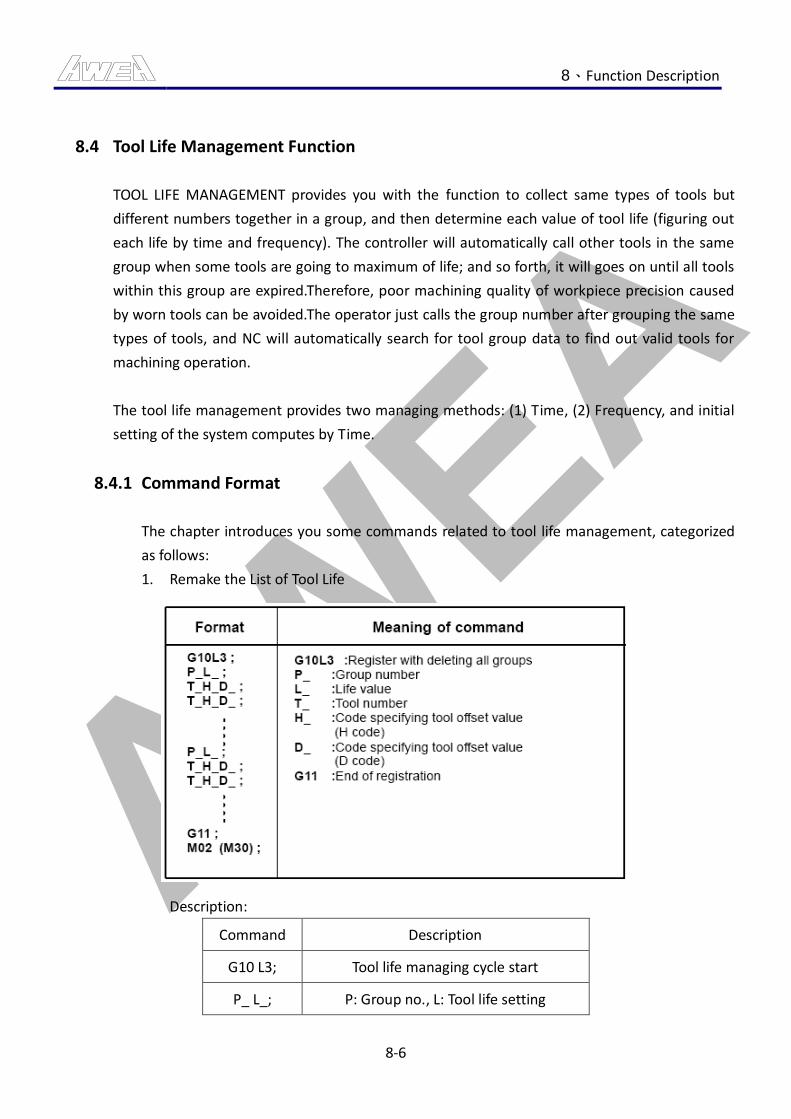
AWEA 8、Function Description
8-6
8.4 Tool Life Management Function
TOOL LIFE MANAGEMENT provides you with the function to collect same types of tools but
different numbers together in a group, and then determine each value of tool life (figuring out
each life by time and frequency). The controller will automatically call other tools in the same
group when some tools are going to maximum of life; and so forth, it will goes on until all tools
within this group are expired.Therefore, poor machining quality of workpiece precision caused
by worn tools can be avoided.The operator just calls the group number after grouping the same
types of tools, and NC will automatically search for tool group data to find out valid tools for
machining operation.
The tool life management provides two managing methods: (1) Time, (2) Frequency, and initial
setting of the system computes by Time.
8.4.1 Command Format
The chapter introduces you some commands related to tool life management, categorized
as follows:
1. Remake the List of Tool Life
Description:
Command Description
G10 L3; Tool life managing cycle start
P_ L_; P: Group no., L: Tool life setting
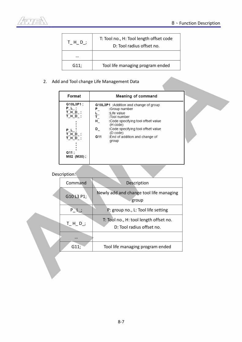
AWEA 8、Function Description
8-7
T_ H_ D_; T: Tool no., H: Tool length offset code
D: Tool radius offset no.
…
G11; Tool life managing program ended
2. Add and Tool change Life Management Data
Description:
Command Description
G10 L3 P1; Newly add and change tool life managing
group
P_ L_; P: group no., L: Tool life setting
T_ H_ D_; T: Tool no., H: tool length offset no.
D: Tool radius offset no.
…
G11; Tool life managing program ended
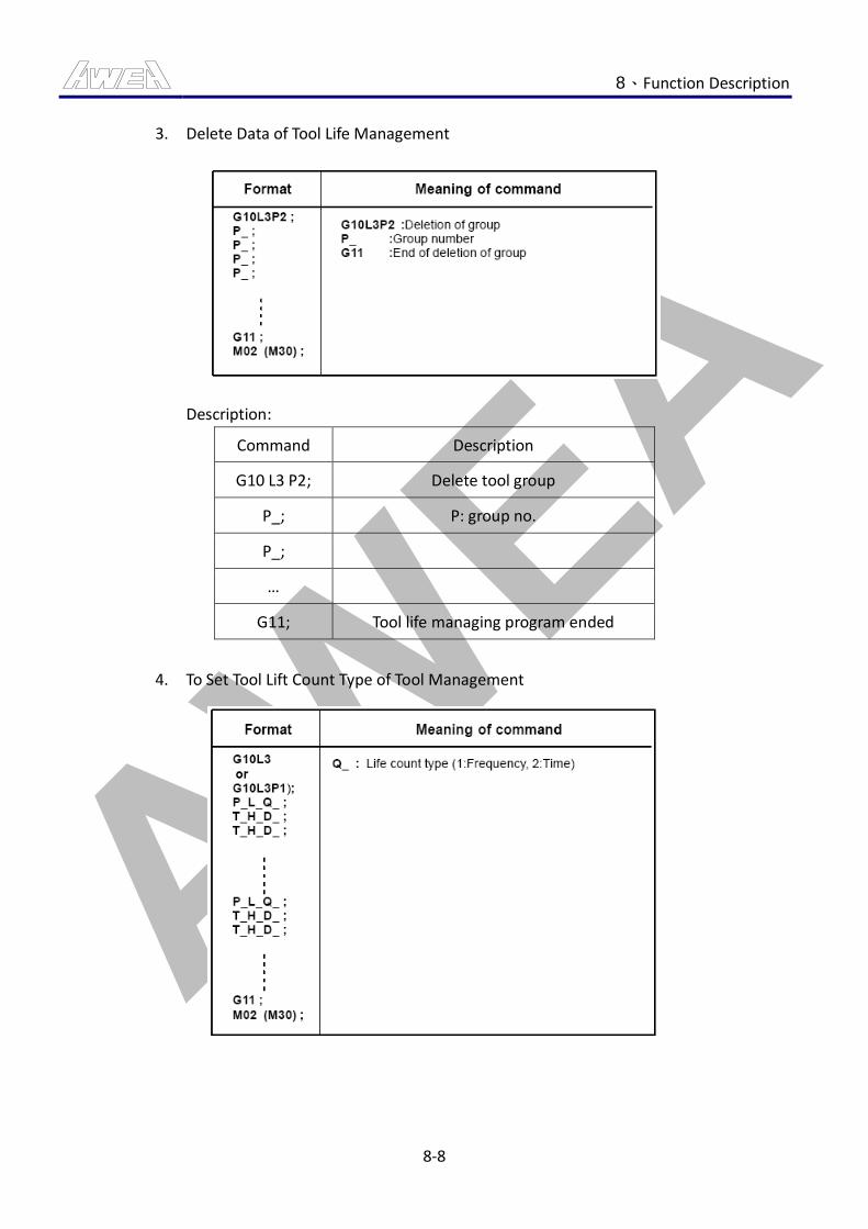
AWEA 8、Function Description
8-8
3. Delete Data of Tool Life Management
Description:
Command Description
G10 L3 P2; Delete tool group
P_; P: group no.
P_;
…
G11; Tool life managing program ended
4. To Set Tool Lift Count Type of Tool Management
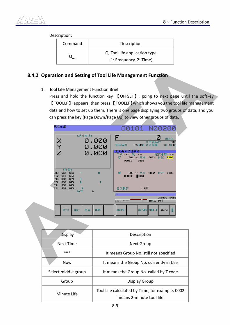
AWEA 8、Function Description
8-9
Description:
Command Description
Q_; Q: Tool life application type
(1: Frequency, 2: Time)
8.4.2 Operation and Setting of Tool Life Management Function
1. Tool Life Management Function Brief
Press and hold the function key 【OFFSET】, going to next page until the softkey
【TOOLLF】 appears, then press 【TOOLLF】which shows you the tool life management
data and how to set up them. There is one page displaying two groups of data, and you
can press the key (Page Down/Page Up) to view other groups of data.
Display Description
Next Time Next Group
*** It means Group No. still not specified
Now It means the Group No. currently in Use
Select middle group It means the Group No. called by T code
Group Display Group
Minute Life Tool Life calculated by Time, for example, 0002
means 2-minute tool life
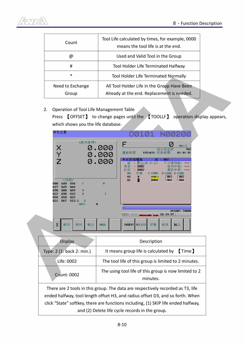
AWEA 8、Function Description
8-10
Count Tool Life calculated by times, for example, 0000
means the tool life is at the end.
@ Used and Valid Tool in the Group
# Tool Holder Life Terminated Halfway
* Tool Holder Life Terminated Normally
Need to Exchange
Group
All Tool Holder Life in the Group Have Been
Already at the end. Replacement is needed.
2. Operation of Tool Life Management Table
Press 【OFFSET】 to change pages until the 【TOOLLF】 operation display appears,
which shows you the life database.
Display Description
Type: 2 (1: back 2: min.) It means group life is calculated by 【Time】
Life: 0002 The tool life of this group is limited to 2 minutes.
Count: 0002 The using tool life of this group is now limited to 2
minutes.
There are 2 tools in this group. The data are respectively recorded as T3, life
ended halfway, tool length offset H3, and radius offset D3, and so forth. When
click “State” softkey, there are functions including, (1) SKIP life ended halfway,
and (2) Delete life cycle records in the group.
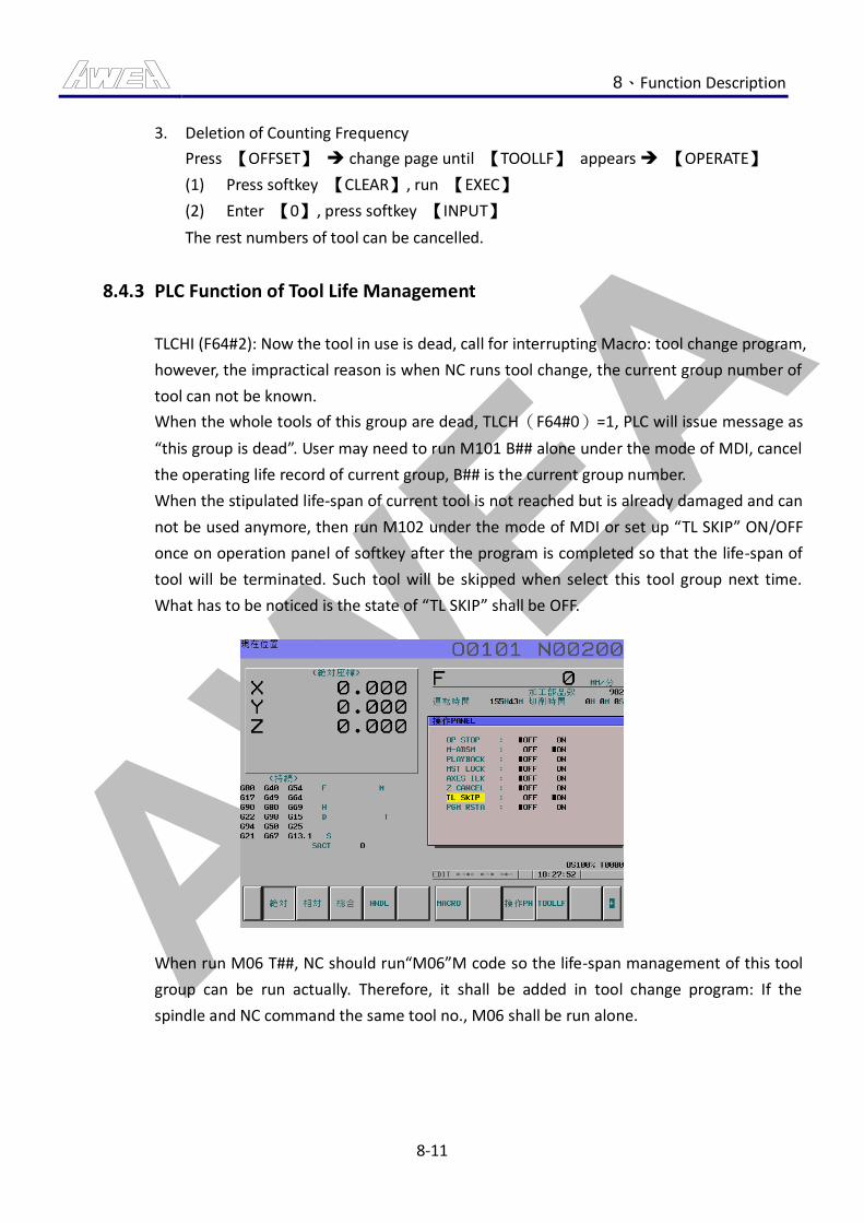
AWEA 8、Function Description
8-11
3. Deletion of Counting Frequency
Press 【OFFSET】 change page until 【TOOLLF】 appears 【OPERATE】
(1) Press softkey 【CLEAR】, run 【EXEC】
(2) Enter 【0】, press softkey 【INPUT】
The rest numbers of tool can be cancelled.
8.4.3 PLC Function of Tool Life Management
TLCHI (F64#2): Now the tool in use is dead, call for interrupting Macro: tool change program,
however, the impractical reason is when NC runs tool change, the current group number of
tool can not be known.
When the whole tools of this group are dead, TLCH(F64#0)=1, PLC will issue message as
“this group is dead”. User may need to run M101 B## alone under the mode of MDI, cancel
the operating life record of current group, B## is the current group number.
When the stipulated life-span of current tool is not reached but is already damaged and can
not be used anymore, then run M102 under the mode of MDI or set up “TL SKIP” ON/OFF
once on operation panel of softkey after the program is completed so that the life-span of
tool will be terminated. Such tool will be skipped when select this tool group next time.
What has to be noticed is the state of “TL SKIP” shall be OFF.
When run M06 T##, NC should run“M06”M code so the life-span management of this tool
group can be run actually. Therefore, it shall be added in tool change program: If the
spindle and NC command the same tool no., M06 shall be run alone.
AWEA 8、Function Description
8-12
8.4.4 Message Description of Tool Life Management
Program Numbering Description
MS2013 TOOL GROUP LIFE END
The tool group is dead, run M101 B##
under the mode of MDI, cancel the
message and life-span information of
tool group.
MS2031 TOOL LIFE END
The current tool is dead, run M103
under the mode of MDI, cancel the
message.
8.4.5 Examples Description
If assume the applied tool quantity of current tool magazine is 120pcs, to apply the function
of life-span management of tool, the first group uses face mill tools and the tools are T1, T2
and T3 separately. The second group uses drilling tools and the tools are T4 and T5. The
method to stipulate the tool group is as below:
Program Description
G10 L3; Tool life managing cycle start
P1 L2; Life of first group is twice (life depends on the
parameter setting)
T1 H1 D4;
Tool setting of the first group T2 H2 D5;
T3 H3 D6;
P2 L1; Life of the second group is one time
T4 H7; Tool setting of 2nd group
T5 H8;
G11; Tool life managing program ended
M30; Program ended
※T1,T2…:It means the actual tool no. is first tool, second tool and so on.
※H*,D*:They are length offset and radius offset separately.
AWEA 8、Function Description
8-13
The below points shall be noticed if apply the life-span management of tool:
1. If the first group tools (face mill tools) are T1 and T2 and the second group tools
(drilling tools) are T3 and T4, in which T3 is dead. If user would like to use face mill tool,
NC will send out T1 to machine after running.M6 T1001. NC will not send out T2 to
machine unless T1 is dead. If user would like to use drilling tool, NC will send out T4 to
machine after running M6 T1002 as T3 is already dead and will not be used anymore.
2. If use does not want to apply the life-span management of tool, NC can take any tool
upon request. For example, M6 T2 is to take T2 tool directly, even if it is M6 T3, NC will
still do it accordingly and now NC does not calculate the life-span of tool.
3. If a tool is dead and user would like to change a new tool, the old information
remained in the tool life-span management table shall be cleaned and the steps are:
【OFFSET】 【TOOLLF】 【OPERATE】 【EDIT】 【STATE】 【SELECT
TOOL】 【CLEAN】.
4. While setting up a tool life-span table, the columns of tool radius and length offset can
be entered in advance. When user would like to use its offset, the orders are; M06
T1001; G43 H99; G41 D99.H99 means the column of length offset built in the tool
life-span table, D99 means the column of radius offset built in the tool life-span table,
and if a offset is required to be cancelled, please use G43 H00; G41 D00.
AWEA 8、Function Description
8-14
8.5 Color Instruction for Machine Tri-color Indicator
Main function of Mute Mode of Tri-color Indicator is described as below:
1. When no one runs it in the midnight, the sound of warning buzzer will influence the
neighbors, therefore, a quiet mode is provided.
2. When client would like to stop warning buzzer temporarily, a quiet mode is provided.
CAUTION
1. While quiet mode is running, there will be no sound to remind the operator when an alarm
happens. Please pay attention to use this.
8.5.1 General Action Description
1. Buzzer is preset as valid under general condition.
2. When an alarm happens, the buzzer will start up and output a proper three-color
indicator as its condition.
3. When an alarm happens, the key light of 【NOISE ELIMINATION OF BUZZER】 will glitter
every 0.5 second.
4. Now if press the key of 【NOISE ELIMINATION OF BUZZER】, the noise of buzzer will be
eliminated and the light will turn into solid light.
5. Press the key of 【NOISE ELIMINATION OF BUZZER】 once again to eliminate the noise
of buzzer, the periodic flash occurs in the 0.5 second of recovery.
8.5.2 Mute Mode Function
After starting the quiet mode of three-color indicator, when an alarm happens, the buzzer
will not act but will output a proper three-color indicator as its condition.
8.5.3 Mute Mode Operation
1. Mute Mode Start:
Press the key of 【NOISE ELIMINATION OF BUZZER】 for three seconds, the quiet mode
of three-color indicator can be entered.
2. Mute Mode Status:
When the mute mode starts, the【BUZZER MUTE】 button light will be blinking slowly
by the frequency 0.5s on and 1.5s off.
AWEA 8、Function Description
8-15
3. Cancellation of Quiet Mode:
(1) Press the key of 【NOISE ELIMINATION OF BUZZER】 once again and the quiet
mode can be cancelled.
(2) After the program ended, press the reset button on the MDI panel, and the mute
mode can be cancelled.

AWEA 8、Function Description
8-16
8.6 Work Travel Prohibited Areas Setting Function
The function to set up the prohibited area during valid process is to define the prohibited range
of valid valid area through prograM command method (Shown as Fig 8.6-1).By setting up the
prohibited area during valid process can protect the workpiece fixture or other interfered
objects to enhance the safety of machine.The definition of range is mainly set up from the
distance of machine coordinate HOME.The limit+ and limit- of X, Y and Z axle can be set up
through the limit instructed by program.Therefore, a prohibited area can be changed according
to the size of workpiece that requires protection.
CAUTION
1. After the power is on, the function is only valid after running the operation of HOME return
manually.
2. After the power is on, the initial state of machine is to cancel the function of setting up the
prohibited area during valid process. The steps of setting up the prohibited area during
valid process shall be run again.
( X , Y , Z)
( I , J , K)
Fig 8.6-1 Work Travel Prohibited Areas Schematic Diagram
8.6.1 Work Travel Prohibited Areas Setting Description
1. Mode switched to EDIT mode.
2. Program edit image, edit the orders of G22 Xx Yy Zz Ii Jj Kk.
Command Description:
(1) Xx: X axis positive travel limited setting value in work travel prohibited area.
(2) Yy: Y axis positive travel limited setting value in work travel prohibited area.
(3) Zz:Z axis positive travel limited setting value in work travel prohibited area.
(4) Ii: X axis negative travel limited setting value in work travel prohibited area.
(5) Jj: Y axis negative travel limited setting value in work travel prohibited area.
(6) Kk: Z axis negative travel limited setting value in work travel prohibited area.
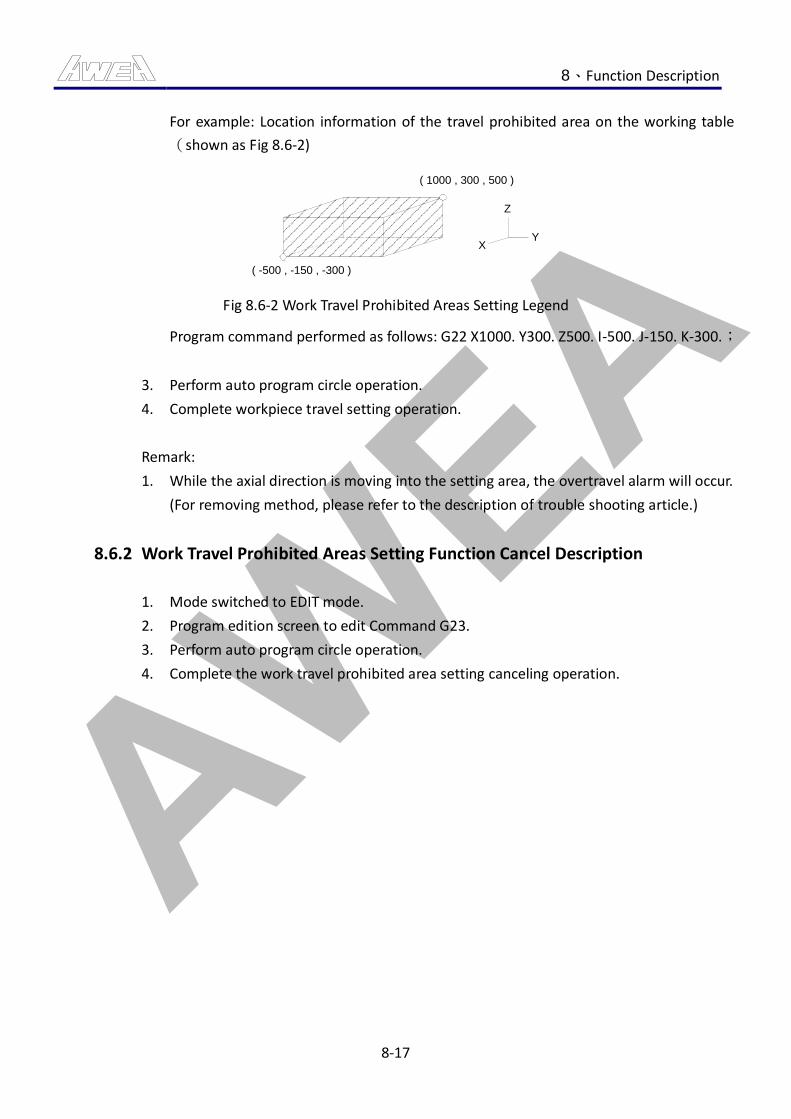
AWEA 8、Function Description
8-17
For example: Location information of the travel prohibited area on the working table
(shown as Fig 8.6-2)
( 1000 , 300 , 500 )
( -500 , -150 , -300 )
Y
Z
X
Fig 8.6-2 Work Travel Prohibited Areas Setting Legend
Program command performed as follows: G22 X1000. Y300. Z500. I-500. J-150. K-300.;
3. Perform auto program circle operation.
4. Complete workpiece travel setting operation.
Remark:
1. While the axial direction is moving into the setting area, the overtravel alarm will occur.
(For removing method, please refer to the description of trouble shooting article.)
8.6.2 Work Travel Prohibited Areas Setting Function Cancel Description
1. Mode switched to EDIT mode.
2. Program edition screen to edit Command G23.
3. Perform auto program circle operation.
4. Complete the work travel prohibited area setting canceling operation.
AWEA 8、Function Description
8-18
8.7 Energy Saving
Because of the serious impact of global warming to the earth, each country has no choice but to
adopt many energy saving projects. Therefore, AWEA also proceeds with the development for
energy saving aspect and further brings up the functions of standby mode and ECO mode of
chip conveyor.
CAUTION
1. After the machine is under the standby mode, please run the warm-up operation again
after restarting.
8.7.1 Stand-By Mode Description
1. Functional description
When the machine is stateless, it is wasted to consume a lot of standby power. For the
above mentioned reason, a standby mode is developed and the main function is to lock
the servo drive and stop motion for some large loading power source to achieve the
result of energy saving.
Remark:
Definition of Stateless: without running program and operating spindle and servo, but a
state of emergency can not be considered as stateless.
2. Start method:
(1) When the machine maintains stateless for 30 minutes, it will enter the standby
mode.
(2) After entering the standby mode, the key light of 【SERVO ON】 will present a
slow speed glittering state and the mandatory indicator will present a solid light
state, meanwhile, the message of “SYSTEM STANDBY, SVON PB REVERT” will
present to warn the user.
(3) When the machine is under the standby mode, the axial direction, spindle, cycle
startup, coolant and relevant functions can not be used.
3. Restore method:
(1) Press the key of 【SERVO ON】once again and the normal operating state can be
recovered.
AWEA 8、Function Description
8-19
8.7.2 Chip Conveyor Green Mode Description
1. Functional description :
The operating method for general chip conveyor is a continuous operating method, in
which the chip conveyor still keeps operating after the chips are all cleaned up. This will
not only reduce the life-span of motor but cause unnecessary power waste. For the
above, the ECO mode of chip conveyor is developed. It takes a time control method for
operation. This will not only clean the chips validly but achieve the result of energy
saving.
2. Start method:
(1) After environmentally friendly mode function of chip conveyor is started.
(2) Perform Manual/Auto Chip Conveyor Operation(For detailed operation steps,
please refer to manual/ auto chip conveyor operation sec. description)
(3) The motor operating method of chip conveyor is a operating method of fixed
time, to start for three minutes and stop for five minutes.
(4) Upon chip conveyor running, 【CHIP CONVEYOR START】button will always be lit.
AWEA 8、Function Description
8-20
8.8 Spindle Load Monitoring Function (Optional)
The spindle load monitoring function can be divided into hardware and software now. The main
function is to protect the spindle, tool and blade. When the spindle is under high speed
machining, once it is overloaded, the tool may be worn and torn quickly or the workpiece may
be damaged. If the spindle load monitoring function is applied. The above states may be
reduced. When the spindle is overloaded, the feed hold or single stop can be run directly to
prevent the spindle, tool and blade from being damaged to enhance the service life-span of
spindle and tool.
8.8.1 Spindle Load Monitoring Operation (Software)
1. Spindle load monitoring format description
M100: Spindle Load Monitoring Function macro command.
Ww:Spindle load value setting.
(Monitoring spindle load value setting, setting range is 0~115%)
Kk: Action type setting.
(K0: When the conditions reached, perform Feed Hold.)
(K1: When the conditions reached, perform Single Block.)
Remark:
(1) All the arguments need to be added with a decimal point.
2. Spindle load monitoring (Software) Operation Steps:
(1) Mode switching to “AUTO, MDI” mode
(2) Prior to machining program, run M100 Ww Kk (refer to format Instruction for W
and K). For the spindle load protection value and processing mode of overloading,
both will be carried out according to the order instructed by operator.
(3) Complete spindle load monitoring (Software) Operation.
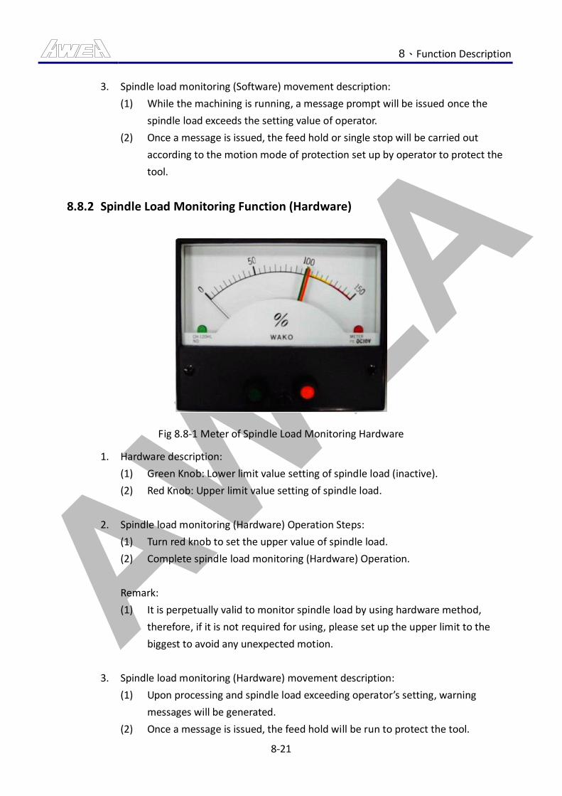
AWEA 8、Function Description
8-21
3. Spindle load monitoring (Software) movement description:
(1) While the machining is running, a message prompt will be issued once the
spindle load exceeds the setting value of operator.
(2) Once a message is issued, the feed hold or single stop will be carried out
according to the motion mode of protection set up by operator to protect the
tool.
8.8.2 Spindle Load Monitoring Function (Hardware)
Fig 8.8-1 Meter of Spindle Load Monitoring Hardware
1. Hardware description:
(1) Green Knob: Lower limit value setting of spindle load (inactive).
(2) Red Knob: Upper limit value setting of spindle load.
2. Spindle load monitoring (Hardware) Operation Steps:
(1) Turn red knob to set the upper value of spindle load.
(2) Complete spindle load monitoring (Hardware) Operation.
Remark:
(1) It is perpetually valid to monitor spindle load by using hardware method,
therefore, if it is not required for using, please set up the upper limit to the
biggest to avoid any unexpected motion.
3. Spindle load monitoring (Hardware) movement description:
(1) Upon processing and spindle load exceeding operator’s setting, warning
messages will be generated.
(2) Once a message is issued, the feed hold will be run to protect the tool.
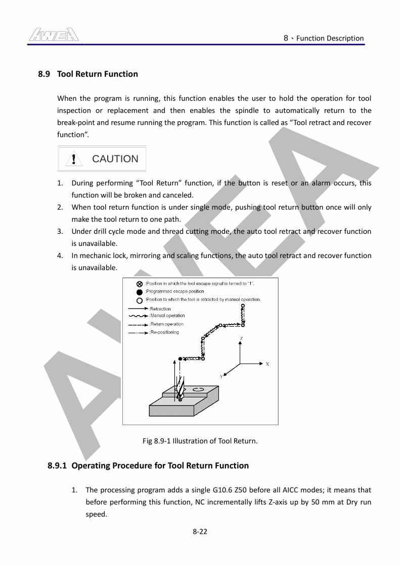
AWEA 8、Function Description
8-22
8.9 Tool Return Function
When the program is running, this function enables the user to hold the operation for tool
inspection or replacement and then enables the spindle to automatically return to the
break-point and resume running the program. This function is called as “Tool retract and recover
function”.
CAUTION
1. During performing “Tool Return” function, if the button is reset or an alarm occurs, this
function will be broken and canceled.
2. When tool return function is under single mode, pushing tool return button once will only
make the tool return to one path.
3. Under drill cycle mode and thread cutting mode, the auto tool retract and recover function
is unavailable.
4. In mechanic lock, mirroring and scaling functions, the auto tool retract and recover function
is unavailable.
‵
Fig 8.9-1 Illustration of Tool Return.
8.9.1 Operating Procedure for Tool Return Function
1. The processing program adds a single G10.6 Z50 before all AICC modes; it means that
before performing this function, NC incrementally lifts Z-axis up by 50 mm at Dry run
speed.
AWEA 8、Function Description
8-23
2. When the program is running, press the button 【FEED HOLD】 to enter holding status
and then press the button 【TOOL RETURN】 to perform tool return function. During
the returning, the indicator light of the button 【TOOL RETURN】 will “remain light”.
3. NC follows G10.6 command to lift Z-axis up for tool returning, and the indicator light of
the button 【TOOL RETURN】 “remains light”.
4. Switch to manual mode and move the axes with MPG. You can only move single axis
every time. NC will memorize the paths. The maximum steps able to be memorized are
about 10.
5. After replacing the tool or doing other things, switch back to auto mode and then press
the button 【TOOL RETURN】. The indicator light will “blink”.
6. The servo axis follows the memorized paths of original manual operation in reverse
direction and returns to break-point. When it reaches tool returning point of Z-axis, the
indicator will “light up”.
7. Press the button 【CYCLE START】. NC will return to the break-point at Dry run speed
and the button light will be OFF.
8. Press the button 【CYCLE START】 again. Continue processing program with program
feed.
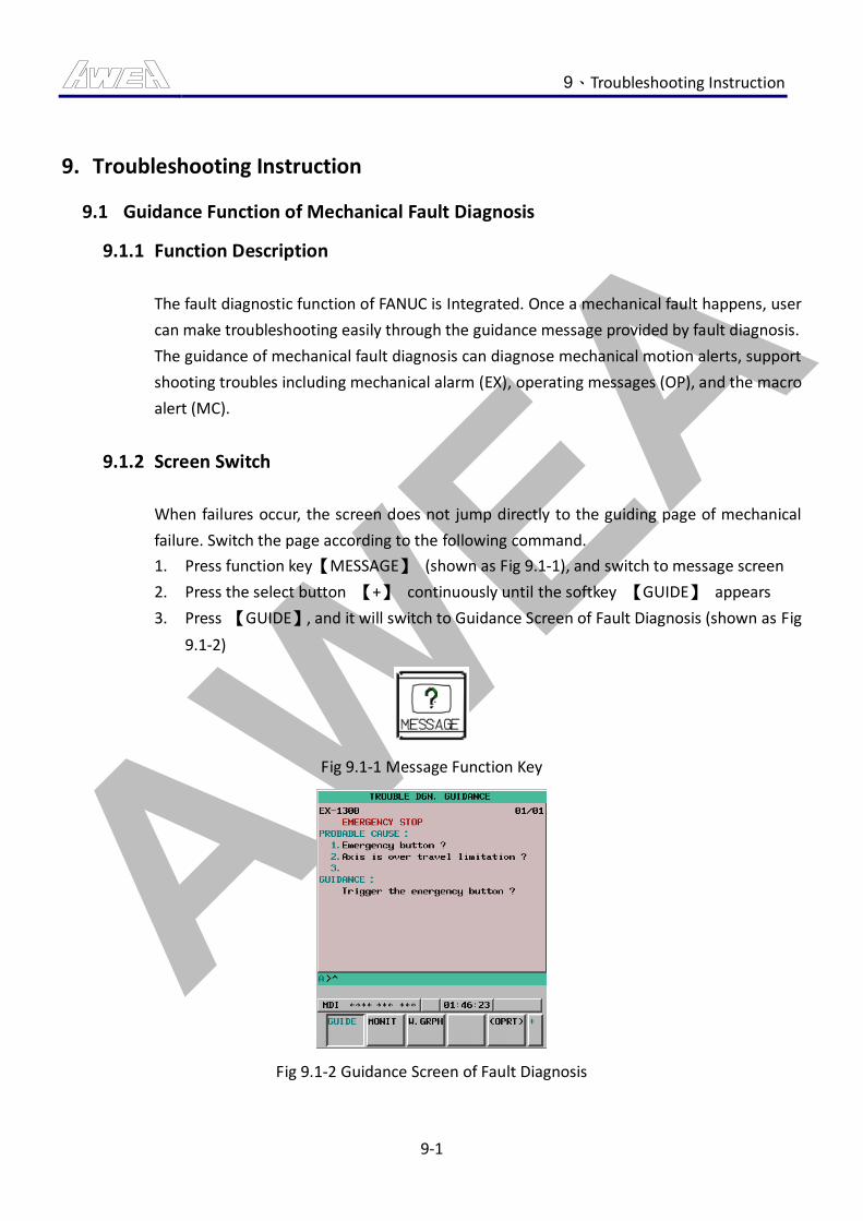
AWEA 9、Troubleshooting Instruction
9-1
9. Troubleshooting Instruction
9.1 Guidance Function of Mechanical Fault Diagnosis
9.1.1 Function Description
The fault diagnostic function of FANUC is Integrated. Once a mechanical fault happens, user
can make troubleshooting easily through the guidance message provided by fault diagnosis.
The guidance of mechanical fault diagnosis can diagnose mechanical motion alerts, support
shooting troubles including mechanical alarm (EX), operating messages (OP), and the macro
alert (MC).
9.1.2 Screen Switch
When failures occur, the screen does not jump directly to the guiding page of mechanical
failure. Switch the page according to the following command.
1. Press function key【MESSAGE】 (shown as Fig 9.1-1), and switch to message screen
2. Press the select button 【+】 continuously until the softkey 【GUIDE】 appears
3. Press 【GUIDE】, and it will switch to Guidance Screen of Fault Diagnosis (shown as Fig
9.1-2)
Fig 9.1-1 Message Function Key
Fig 9.1-2 Guidance Screen of Fault Diagnosis
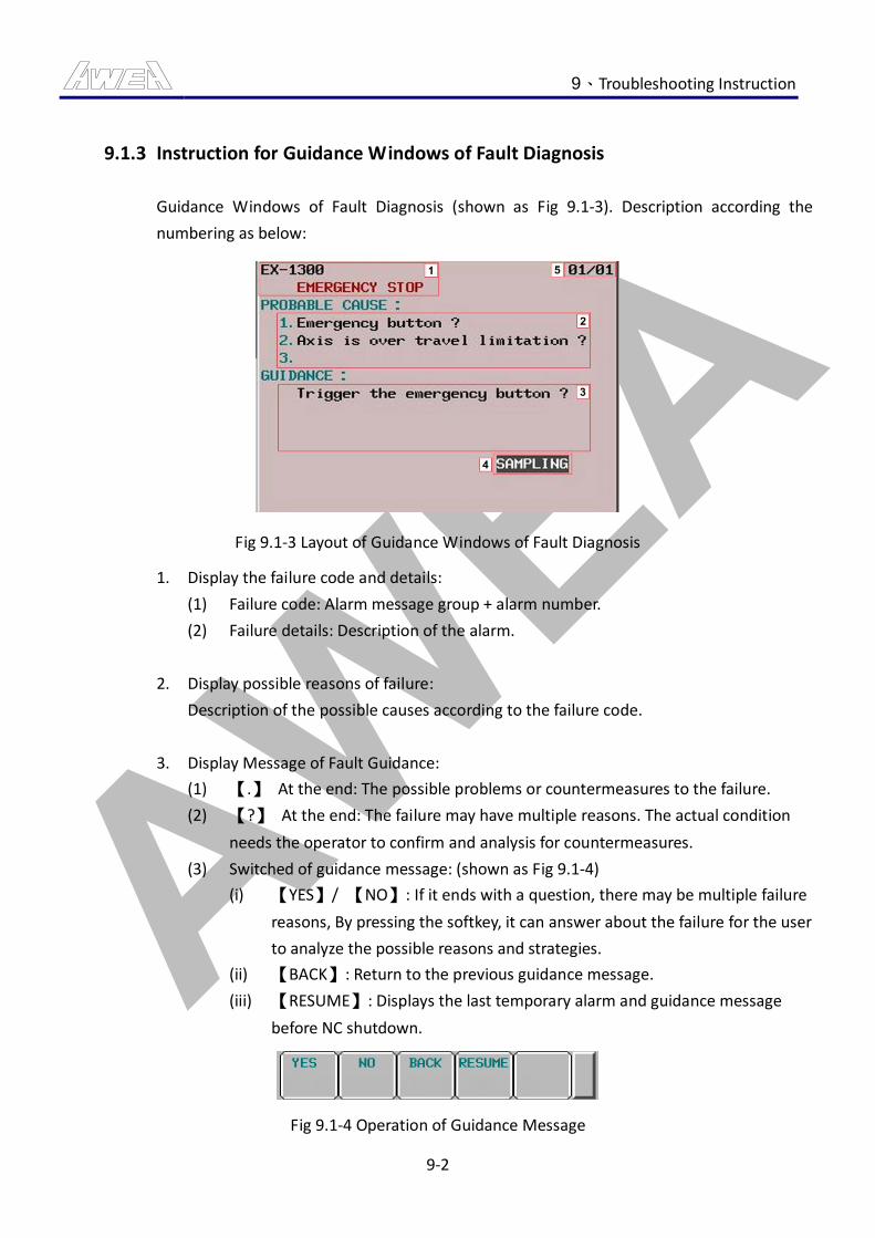
AWEA 9、Troubleshooting Instruction
9-2
9.1.3 Instruction for Guidance Windows of Fault Diagnosis
Guidance Windows of Fault Diagnosis (shown as Fig 9.1-3). Description according the
numbering as below:
Fig 9.1-3 Layout of Guidance Windows of Fault Diagnosis
1. Display the failure code and details:
(1) Failure code: Alarm message group + alarm number.
(2) Failure details: Description of the alarm.
2. Display possible reasons of failure:
Description of the possible causes according to the failure code.
3. Display Message of Fault Guidance:
(1) 【.】 At the end: The possible problems or countermeasures to the failure.
(2) 【?】 At the end: The failure may have multiple reasons. The actual condition
needs the operator to confirm and analysis for countermeasures.
(3) Switched of guidance message: (shown as Fig 9.1-4)
(i) 【YES】/ 【NO】: If it ends with a question, there may be multiple failure
reasons, By pressing the softkey, it can answer about the failure for the user
to analyze the possible reasons and strategies.
(ii) 【BACK】: Return to the previous guidance message.
(iii) 【RESUME】: Displays the last temporary alarm and guidance message
before NC shutdown.
Fig 9.1-4 Operation of Guidance Message
AWEA 9、Troubleshooting Instruction
9-3
4. Status Display:
(1) 【SAMPLING】:
Mean that NC is waiting for the information of sampling alarm, servo axis, and
the spindle. The information can also be checked in time.
(2) 【LATCHED】:
Mean that when the servo axis/spindle alarm occurs at the same time, the NC
will immediately remember the information of servo axis and spindle at the
moment.
(3) 【RESUMING】:
Press the softkey 【RESUME】, the screen will display the last warning and
guidance messages before shutting down the last NC temporary live, will display
the status 【RESUMING】.
5. Display alarm numbers:
When several alarms happen at the same time, use Page key 【PAGE ↓】/【PAGE ↑】
to select the guidance message.
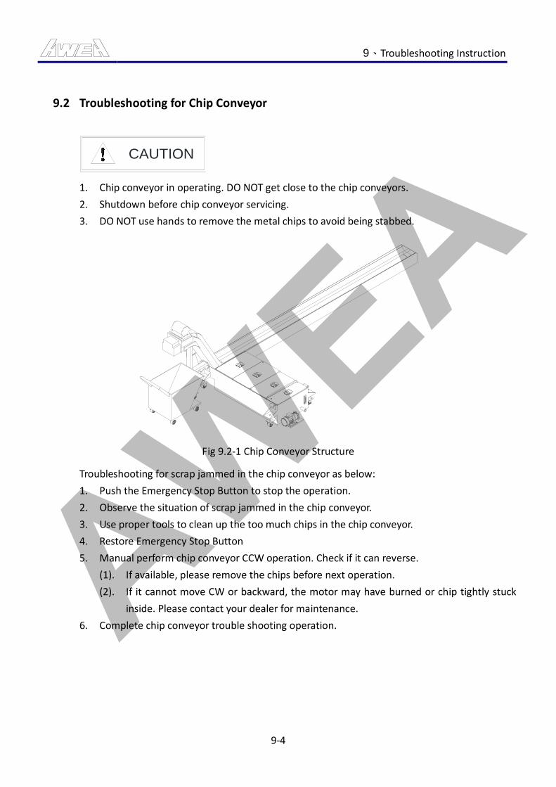
AWEA 9、Troubleshooting Instruction
9-4
9.2 Troubleshooting for Chip Conveyor
CAUTION
1. Chip conveyor in operating. DO NOT get close to the chip conveyors.
2. Shutdown before chip conveyor servicing.
3. DO NOT use hands to remove the metal chips to avoid being stabbed.
Fig 9.2-1 Chip Conveyor Structure
Troubleshooting for scrap jammed in the chip conveyor as below:
1. Push the Emergency Stop Button to stop the operation.
2. Observe the situation of scrap jammed in the chip conveyor.
3. Use proper tools to clean up the too much chips in the chip conveyor.
4. Restore Emergency Stop Button
5. Manual perform chip conveyor CCW operation. Check if it can reverse.
(1). If available, please remove the chips before next operation.
(2). If it cannot move CW or backward, the motor may have burned or chip tightly stuck
inside. Please contact your dealer for maintenance.
6. Complete chip conveyor trouble shooting operation.
AWEA 9、Troubleshooting Instruction
9-5
9.3 Troubleshooting of Auto Tool Change (ATC)
For the automatic control method of tool changing, adopt the procedures to control and
continuously complete all steps.So it is necessary to adopt following steps to exclude the
abnormal conditions if any abnormal conditions causing machine shutdown or emergency stop
during automatic tool changing process.
CAUTION
1. Tool Magazine in operating. DO NOT get close to the Spindle.
2. Shutdown before Tool Magazine servicing.
Auto Tool Change Troubleshooting description
1. Switched the mode to “Handle” mode and press the button of “Emergency Stop” to cancel
Original control procedure and further restore the emergency switch.
2. Switch Tool MAG Panel key switched from 【LOCK】to【MANUAL】.
3. After selecting needed functions on the tool magazine operator panel, press the button of
【MANUAL STEP】 and restore the tool magazine mechanism to initial status.
The initial status of tool magazine mechanism is as below:
(1). Arm in the middle.
(2). Arm in the upper position.
4. Use the button of 【T#DISP】 to check up if current spindle, arm, and tool magazine
number are correct. If incorrect, use the tool no. alter command to alter the tool no.
(1). Tool magazine tool no. alteration: M96 K1 T, the desired tool no.
(2). Arm tool no. alteration: M96 K2 T, the desired tool no.
(3). Spindle tool no. alteration: M96 K3 T, the desired tool no.
5. Complete abnormal auto tool changing troubleshooting operation.
AWEA 9、Troubleshooting Instruction
9-6
9.4 Troubleshooting of Axial Movement Overtravel
Axial overtravel protection can be divided into hardware overtravel and software overtravel, as
following descriptions:
1. Hardware Travel Protection: The motion of limited switch causes warnings and stops
alarms.
2. Software Travel Protection: Mechanical coordinates exceed the software travel limit setting.
CAUTION
1. Before moving axis, make sure that no operators are inside/ around the machine. Then the
movement can be performed.
2. Make sure the travel direction, it will cause the damage of mechanical structures if any
error operation overtravel direction.
9.4.1 Troubleshooting of Hardware Overtravel
1. If any alarm for hardware overtravel, press the button of 【TRAVEL RELEASE】.
2. Use manual rotary wheel to move the axes out of OT range. (Make sure it moved out
overtravel direction. The travel protection is invalid under the status of travel release.)
As moving out of OT ranges, the indicator of 【TRAVEL RELEASE】 will be extinguished.
3. Complete troubleshooting operation of hardware overtravel.
9.4.2 Troubleshooting of Software Overtravel
1. Upon generating hardware over traveling alarm, perform 【RELEASE TRAVEL】button.
OT0500: OVER TRAVEL : +n.
OT0501: OVER TRAVEL : -n.
OT0502: OVER TRAVEL : +n.
OT0503: OVER TRAVEL : -n.
2. Use manual rotary wheel to move in opposite direction.
(As occurring software overtravel, the servo axis is just able to move in opposite
direction.)
3. Press the button of “Reset” on the MDI panel to release alarm.
4. Complete troubleshooting operation of software overtravel.
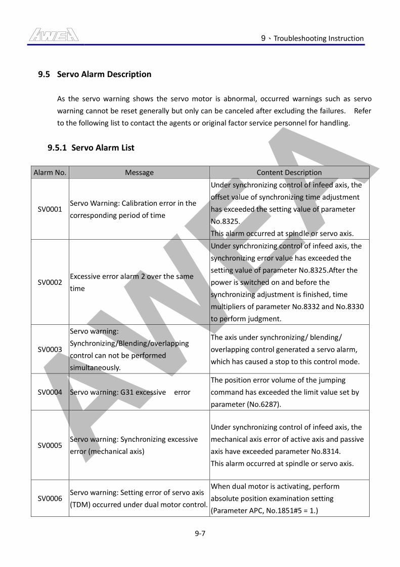
AWEA 9、Troubleshooting Instruction
9-7
9.5 Servo Alarm Description
As the servo warning shows the servo motor is abnormal, occurred warnings such as servo
warning cannot be reset generally but only can be canceled after excluding the failures. Refer
to the following list to contact the agents or original factor service personnel for handling.
9.5.1 Servo Alarm List
Alarm No. Message Content Description
SV0001 Servo Warning: Calibration error in the
corresponding period of time
Under synchronizing control of infeed axis, the
offset value of synchronizing time adjustment
has exceeded the setting value of parameter
No.8325.
This alarm occurred at spindle or servo axis.
SV0002 Excessive error alarm 2 over the same
time
Under synchronizing control of infeed axis, the
synchronizing error value has exceeded the
setting value of parameter No.8325.After the
power is switched on and before the
synchronizing adjustment is finished, time
multipliers of parameter No.8332 and No.8330
to perform judgment.
SV0003
Servo warning:
Synchronizing/Blending/overlapping
control can not be performed
simultaneously.
The axis under synchronizing/ blending/
overlapping control generated a servo alarm,
which has caused a stop to this control mode.
SV0004 Servo warning: G31 excessive error
The position error volume of the jumping
command has exceeded the limit value set by
parameter (No.6287).
SV0005 Servo warning: Synchronizing excessive
error (mechanical axis)
Under synchronizing control of infeed axis, the
mechanical axis error of active axis and passive
axis have exceeded parameter No.8314.
This alarm occurred at spindle or servo axis.
SV0006 Servo warning: Setting error of servo axis
(TDM) occurred under dual motor control.
When dual motor is activating, perform
absolute position examination setting
(Parameter APC, No.1851#5 = 1.)
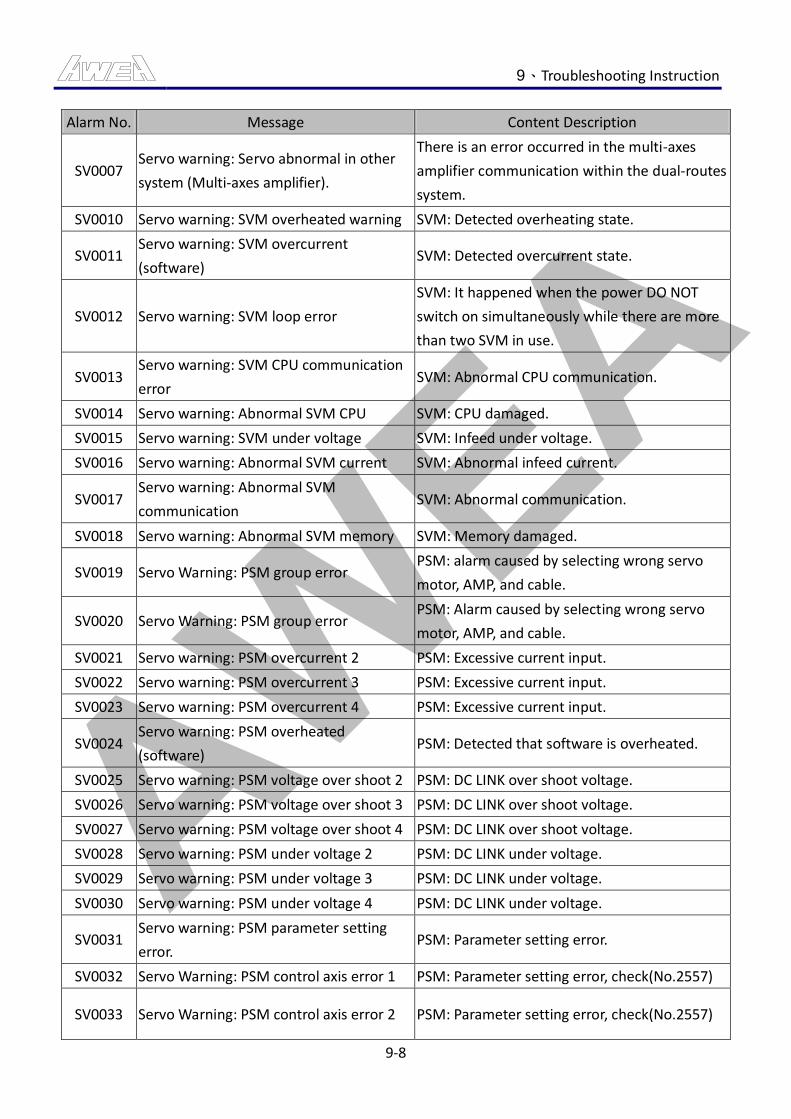
AWEA 9、Troubleshooting Instruction
9-8
Alarm No. Message Content Description
SV0007 Servo warning: Servo abnormal in other
system (Multi-axes amplifier).
There is an error occurred in the multi-axes
amplifier communication within the dual-routes
system.
SV0010 Servo warning: SVM overheated warning SVM: Detected overheating state.
SV0011 Servo warning: SVM overcurrent
(software) SVM: Detected overcurrent state.
SV0012 Servo warning: SVM loop error
SVM: It happened when the power DO NOT
switch on simultaneously while there are more
than two SVM in use.
SV0013 Servo warning: SVM CPU communication
error SVM: Abnormal CPU communication.
SV0014 Servo warning: Abnormal SVM CPU SVM: CPU damaged.
SV0015 Servo warning: SVM under voltage SVM: Infeed under voltage.
SV0016 Servo warning: Abnormal SVM current SVM: Abnormal infeed current.
SV0017 Servo warning: Abnormal SVM
communication SVM: Abnormal communication.
SV0018 Servo warning: Abnormal SVM memory SVM: Memory damaged.
SV0019 Servo Warning: PSM group error PSM: alarm caused by selecting wrong servo
motor, AMP, and cable.
SV0020 Servo Warning: PSM group error PSM: Alarm caused by selecting wrong servo
motor, AMP, and cable.
SV0021 Servo warning: PSM overcurrent 2 PSM: Excessive current input.
SV0022 Servo warning: PSM overcurrent 3 PSM: Excessive current input.
SV0023 Servo warning: PSM overcurrent 4 PSM: Excessive current input.
SV0024 Servo warning: PSM overheated
(software) PSM: Detected that software is overheated.
SV0025 Servo warning: PSM voltage over shoot 2 PSM: DC LINK over shoot voltage.
SV0026 Servo warning: PSM voltage over shoot 3 PSM: DC LINK over shoot voltage.
SV0027 Servo warning: PSM voltage over shoot 4 PSM: DC LINK over shoot voltage.
SV0028 Servo warning: PSM under voltage 2 PSM: DC LINK under voltage.
SV0029 Servo warning: PSM under voltage 3 PSM: DC LINK under voltage.
SV0030 Servo warning: PSM under voltage 4 PSM: DC LINK under voltage.
SV0031 Servo warning: PSM parameter setting
error. PSM: Parameter setting error.
SV0032 Servo Warning: PSM control axis error 1 PSM: Parameter setting error, check(No.2557)
SV0033 Servo Warning: PSM control axis error 2 PSM: Parameter setting error, check(No.2557)
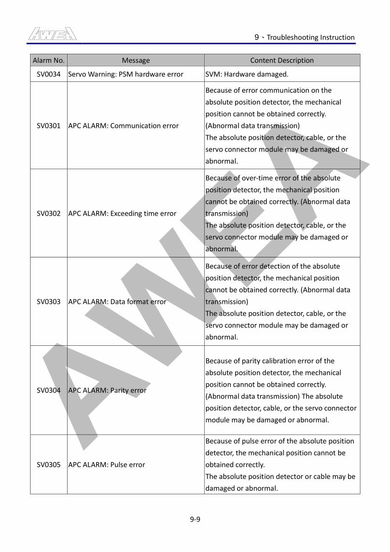
AWEA 9、Troubleshooting Instruction
9-9
Alarm No. Message Content Description
SV0034 Servo Warning: PSM hardware error SVM: Hardware damaged.
SV0301 APC ALARM: Communication error
Because of error communication on the
absolute position detector, the mechanical
position cannot be obtained correctly.
(Abnormal data transmission)
The absolute position detector, cable, or the
servo connector module may be damaged or
abnormal.
SV0302 APC ALARM: Exceeding time error
Because of over-time error of the absolute
position detector, the mechanical position
cannot be obtained correctly. (Abnormal data
transmission)
The absolute position detector, cable, or the
servo connector module may be damaged or
abnormal.
SV0303 APC ALARM: Data format error
Because of error detection of the absolute
position detector, the mechanical position
cannot be obtained correctly. (Abnormal data
transmission)
The absolute position detector, cable, or the
servo connector module may be damaged or
abnormal.
SV0304 APC ALARM: Parity error
Because of parity calibration error of the
absolute position detector, the mechanical
position cannot be obtained correctly.
(Abnormal data transmission) The absolute
position detector, cable, or the servo connector
module may be damaged or abnormal.
SV0305 APC ALARM: Pulse error
Because of pulse error of the absolute position
detector, the mechanical position cannot be
obtained correctly.
The absolute position detector or cable may be
damaged or abnormal.
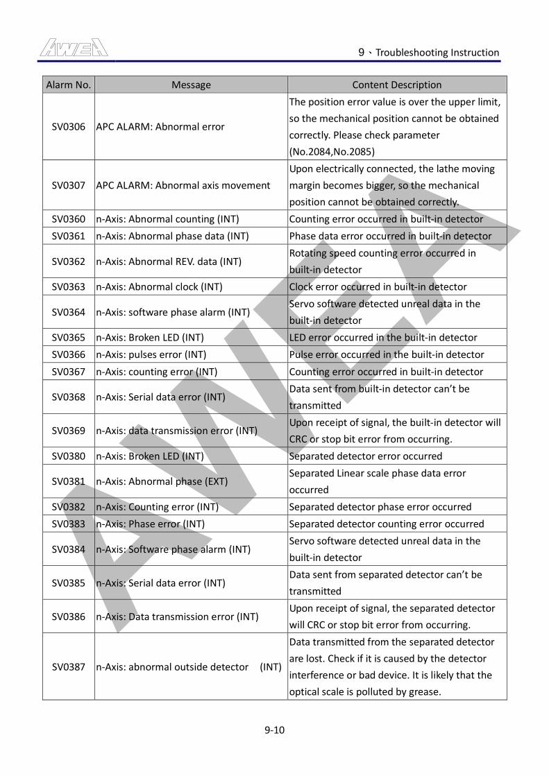
AWEA 9、Troubleshooting Instruction
9-10
Alarm No. Message Content Description
SV0306 APC ALARM: Abnormal error
The position error value is over the upper limit,
so the mechanical position cannot be obtained
correctly. Please check parameter
(No.2084,No.2085)
SV0307 APC ALARM: Abnormal axis movement
Upon electrically connected, the lathe moving
margin becomes bigger, so the mechanical
position cannot be obtained correctly.
SV0360 n-Axis: Abnormal counting (INT) Counting error occurred in built-in detector
SV0361 n-Axis: Abnormal phase data (INT) Phase data error occurred in built-in detector
SV0362 n-Axis: Abnormal REV. data (INT) Rotating speed counting error occurred in
built-in detector
SV0363 n-Axis: Abnormal clock (INT) Clock error occurred in built-in detector
SV0364 n-Axis: software phase alarm (INT) Servo software detected unreal data in the
built-in detector
SV0365 n-Axis: Broken LED (INT) LED error occurred in the built-in detector
SV0366 n-Axis: pulses error (INT) Pulse error occurred in the built-in detector
SV0367 n-Axis: counting error (INT) Counting error occurred in built-in detector
SV0368 n-Axis: Serial data error (INT) Data sent from built-in detector can’t be
transmitted
SV0369 n-Axis: data transmission error (INT) Upon receipt of signal, the built-in detector will
CRC or stop bit error from occurring.
SV0380 n-Axis: Broken LED (INT) Separated detector error occurred
SV0381 n-Axis: Abnormal phase (EXT) Separated Linear scale phase data error
occurred
SV0382 n-Axis: Counting error (INT) Separated detector phase error occurred
SV0383 n-Axis: Phase error (INT) Separated detector counting error occurred
SV0384 n-Axis: Software phase alarm (INT) Servo software detected unreal data in the
built-in detector
SV0385 n-Axis: Serial data error (INT) Data sent from separated detector can’t be
transmitted
SV0386 n-Axis: Data transmission error (INT) Upon receipt of signal, the separated detector
will CRC or stop bit error from occurring.
SV0387 n-Axis: abnormal outside detector (INT)
Data transmitted from the separated detector
are lost. Check if it is caused by the detector
interference or bad device. It is likely that the
optical scale is polluted by grease.
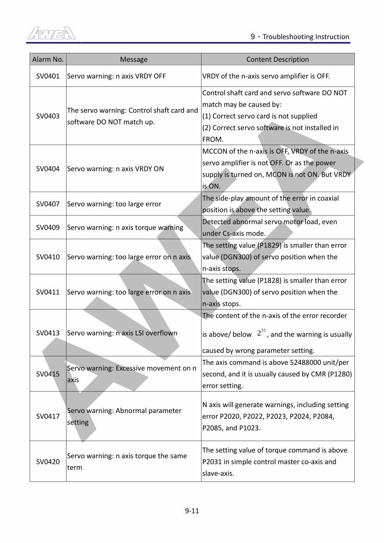
AWEA 9、Troubleshooting Instruction
9-11
Alarm No. Message Content Description
SV0401 Servo warning: n axis VRDY OFF VRDY of the n-axis servo amplifier is OFF.
SV0403 The servo warning: Control shaft card and
software DO NOT match up.
Control shaft card and servo software DO NOT
match may be caused by:
(1) Correct servo card is not supplied
(2) Correct servo software is not installed in
FROM.
SV0404 Servo warning: n axis VRDY ON
MCCON of the n-axis is OFF, VRDY of the n-axis
servo amplifier is not OFF. Or as the power
supply is turned on, MCON is not ON. But VRDY
is ON.
SV0407 Servo warning: too large error The side-play amount of the error in coaxial
position is above the setting value.
SV0409 Servo warning: n axis torque warning Detected abnormal servo motor load, even
under Cs-axis mode.
SV0410 Servo warning: too large error on n axis
The setting value (P1829) is smaller than error
value (DGN300) of servo position when the
n-axis stops.
SV0411 Servo warning: too large error on n axis
The setting value (P1828) is smaller than error
value (DGN300) of servo position when the
n-axis stops.
SV0413 Servo warning: n axis LSI overflown
The content of the n-axis of the error recorder
is above/ below 31
2 , and the warning is usually
caused by wrong parameter setting.
SV0415 Servo warning: Excessive movement on n
axis
The axis command is above 52488000 unit/per
second, and it is usually caused by CMR (P1280)
error setting.
SV0417 Servo warning: Abnormal parameter
setting
N axis will generate warnings, including setting
error P2020, P2022, P2023, P2024, P2084,
P2085, and P1023.
SV0420 Servo warning: n axis torque the same
term
The setting value of torque command is above
P2031 in simple control master co-axis and
slave-axis.
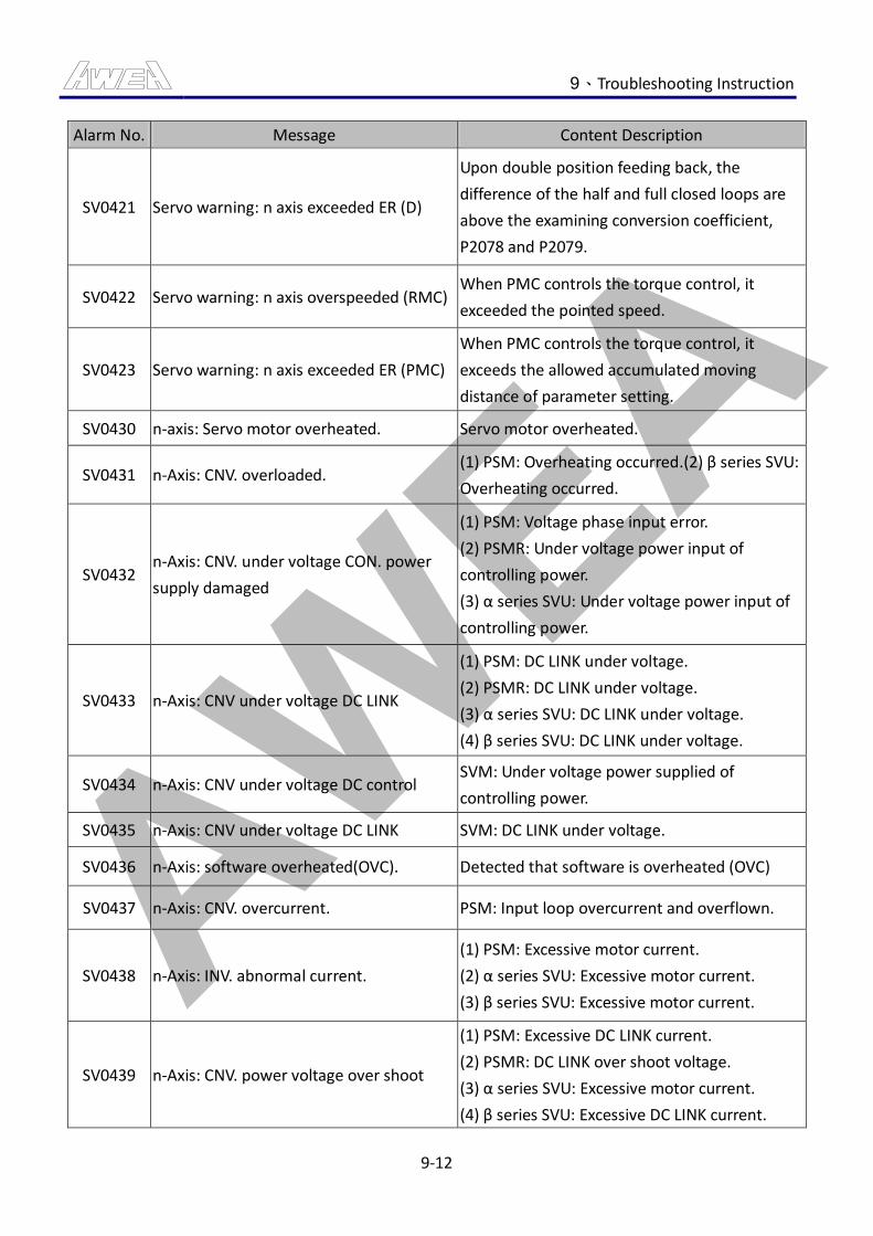
AWEA 9、Troubleshooting Instruction
9-12
Alarm No. Message Content Description
SV0421 Servo warning: n axis exceeded ER (D)
Upon double position feeding back, the
difference of the half and full closed loops are
above the examining conversion coefficient,
P2078 and P2079.
SV0422 Servo warning: n axis overspeeded (RMC) When PMC controls the torque control, it
exceeded the pointed speed.
SV0423 Servo warning: n axis exceeded ER (PMC)
When PMC controls the torque control, it
exceeds the allowed accumulated moving
distance of parameter setting.
SV0430 n-axis: Servo motor overheated. Servo motor overheated.
SV0431 n-Axis: CNV. overloaded. (1) PSM: Overheating occurred.(2) β series SVU:
Overheating occurred.
SV0432 n-Axis: CNV. under voltage CON. power
supply damaged
(1) PSM: Voltage phase input error.
(2) PSMR: Under voltage power input of
controlling power.
(3) α series SVU: Under voltage power input of
controlling power.
SV0433 n-Axis: CNV under voltage DC LINK
(1) PSM: DC LINK under voltage.
(2) PSMR: DC LINK under voltage.
(3) α series SVU: DC LINK under voltage.
(4) β series SVU: DC LINK under voltage.
SV0434 n-Axis: CNV under voltage DC control SVM: Under voltage power supplied of
controlling power.
SV0435 n-Axis: CNV under voltage DC LINK SVM: DC LINK under voltage.
SV0436 n-Axis: software overheated(OVC). Detected that software is overheated (OVC)
SV0437 n-Axis: CNV. overcurrent. PSM: Input loop overcurrent and overflown.
SV0438 n-Axis: INV. abnormal current.
(1) PSM: Excessive motor current.
(2) α series SVU: Excessive motor current.
(3) β series SVU: Excessive motor current.
SV0439 n-Axis: CNV. power voltage over shoot
(1) PSM: Excessive DC LINK current.
(2) PSMR: DC LINK over shoot voltage.
(3) α series SVU: Excessive motor current.
(4) β series SVU: Excessive DC LINK current.
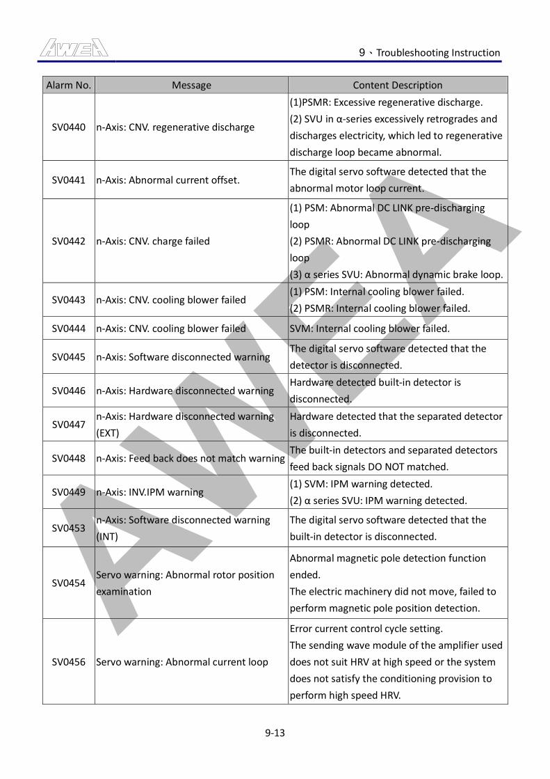
AWEA 9、Troubleshooting Instruction
9-13
Alarm No. Message Content Description
SV0440 n-Axis: CNV. regenerative discharge
(1)PSMR: Excessive regenerative discharge.
(2) SVU in α-series excessively retrogrades and
discharges electricity, which led to regenerative
discharge loop became abnormal.
SV0441 n-Axis: Abnormal current offset. The digital servo software detected that the
abnormal motor loop current.
SV0442 n-Axis: CNV. charge failed
(1) PSM: Abnormal DC LINK pre-discharging
loop
(2) PSMR: Abnormal DC LINK pre-discharging
loop
(3) α series SVU: Abnormal dynamic brake loop.
SV0443 n-Axis: CNV. cooling blower failed (1) PSM: Internal cooling blower failed.
(2) PSMR: Internal cooling blower failed.
SV0444 n-Axis: CNV. cooling blower failed SVM: Internal cooling blower failed.
SV0445 n-Axis: Software disconnected warning The digital servo software detected that the
detector is disconnected.
SV0446 n-Axis: Hardware disconnected warning Hardware detected built-in detector is
disconnected.
SV0447 n-Axis: Hardware disconnected warning
(EXT)
Hardware detected that the separated detector
is disconnected.
SV0448 n-Axis: Feed back does not match warning The built-in detectors and separated detectors
feed back signals DO NOT matched.
SV0449 n-Axis: INV.IPM warning (1) SVM: IPM warning detected.
(2) α series SVU: IPM warning detected.
SV0453 n-Axis: Software disconnected warning
(INT)
The digital servo software detected that the
built-in detector is disconnected.
SV0454 Servo warning: Abnormal rotor position
examination
Abnormal magnetic pole detection function
ended.
The electric machinery did not move, failed to
perform magnetic pole position detection.
SV0456 Servo warning: Abnormal current loop
Error current control cycle setting.
The sending wave module of the amplifier used
does not suit HRV at high speed or the system
does not satisfy the conditioning provision to
perform high speed HRV.
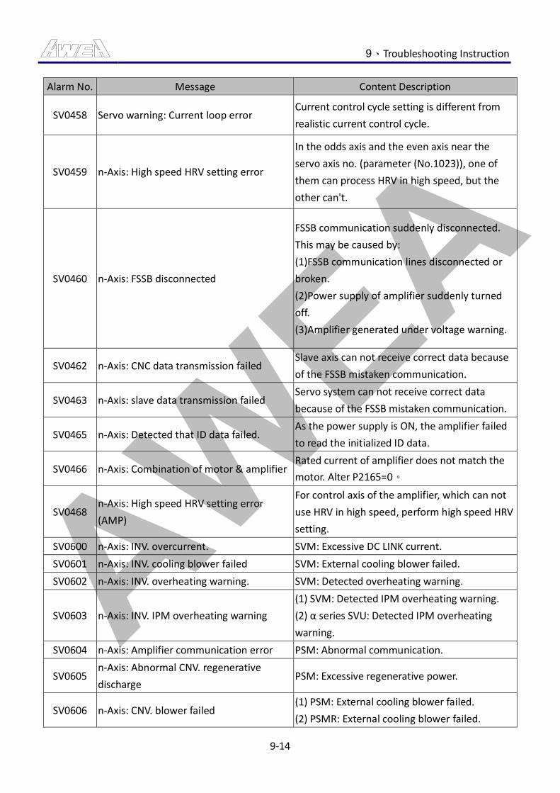
AWEA 9、Troubleshooting Instruction
9-14
Alarm No. Message Content Description
SV0458 Servo warning: Current loop error Current control cycle setting is different from
realistic current control cycle.
SV0459 n-Axis: High speed HRV setting error
In the odds axis and the even axis near the
servo axis no. (parameter (No.1023)), one of
them can process HRV in high speed, but the
other can't.
SV0460 n-Axis: FSSB disconnected
FSSB communication suddenly disconnected.
This may be caused by:
(1)FSSB communication lines disconnected or
broken.
(2)Power supply of amplifier suddenly turned
off.
(3)Amplifier generated under voltage warning.
SV0462 n-Axis: CNC data transmission failed Slave axis can not receive correct data because
of the FSSB mistaken communication.
SV0463 n-Axis: slave data transmission failed Servo system can not receive correct data
because of the FSSB mistaken communication.
SV0465 n-Axis: Detected that ID data failed. As the power supply is ON, the amplifier failed
to read the initialized ID data.
SV0466 n-Axis: Combination of motor & amplifier Rated current of amplifier does not match the
motor. Alter P2165=0。
SV0468 n-Axis: High speed HRV setting error
(AMP)
For control axis of the amplifier, which can not
use HRV in high speed, perform high speed HRV
setting.
SV0600 n-Axis: INV. overcurrent. SVM: Excessive DC LINK current.
SV0601 n-Axis: INV. cooling blower failed SVM: External cooling blower failed.
SV0602 n-Axis: INV. overheating warning. SVM: Detected overheating warning.
SV0603 n-Axis: INV. IPM overheating warning
(1) SVM: Detected IPM overheating warning.
(2) α series SVU: Detected IPM overheating
warning.
SV0604 n-Axis: Amplifier communication error PSM: Abnormal communication.
SV0605 n-Axis: Abnormal CNV. regenerative
discharge PSM: Excessive regenerative power.
SV0606 n-Axis: CNV. blower failed (1) PSM: External cooling blower failed.
(2) PSMR: External cooling blower failed.
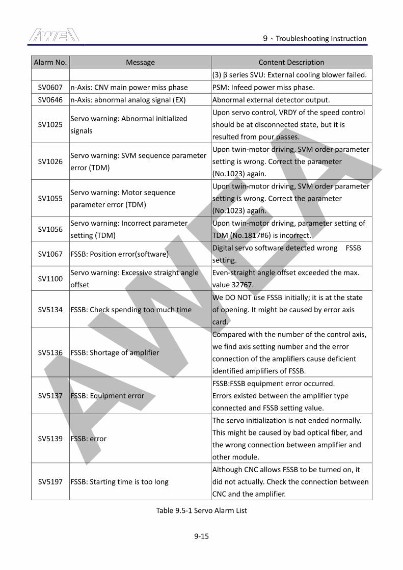
AWEA 9、Troubleshooting Instruction
9-15
Alarm No. Message Content Description
(3) β series SVU: External cooling blower failed.
SV0607 n-Axis: CNV main power miss phase PSM: Infeed power miss phase.
SV0646 n-Axis: abnormal analog signal (EX) Abnormal external detector output.
SV1025 Servo warning: Abnormal initialized
signals
Upon servo control, VRDY of the speed control
should be at disconnected state, but it is
resulted from pour passes.
SV1026 Servo warning: SVM sequence parameter
error (TDM)
Upon twin-motor driving, SVM order parameter
setting is wrong. Correct the parameter
(No.1023) again.
SV1055 Servo warning: Motor sequence
parameter error (TDM)
Upon twin-motor driving, SVM order parameter
setting is wrong. Correct the parameter
(No.1023) again.
SV1056 Servo warning: Incorrect parameter
setting (TDM)
Upon twin-motor driving, parameter setting of
TDM (No.1817#6) is incorrect.
SV1067 FSSB: Position error(software) Digital servo software detected wrong FSSB
setting.
SV1100 Servo warning: Excessive straight angle
offset
Even-straight angle offset exceeded the max.
value 32767.
SV5134 FSSB: Check spending too much time
We DO NOT use FSSB initially; it is at the state
of opening. It might be caused by error axis
card.
SV5136 FSSB: Shortage of amplifier
Compared with the number of the control axis,
we find axis setting number and the error
connection of the amplifiers cause deficient
identified amplifiers of FSSB.
SV5137 FSSB: Equipment error
FSSB:FSSB equipment error occurred.
Errors existed between the amplifier type
connected and FSSB setting value.
SV5139 FSSB: error
The servo initialization is not ended normally.
This might be caused by bad optical fiber, and
the wrong connection between amplifier and
other module.
SV5197 FSSB: Starting time is too long
Although CNC allows FSSB to be turned on, it
did not actually. Check the connection between
CNC and the amplifier.
Table 9.5-1 Servo Alarm List
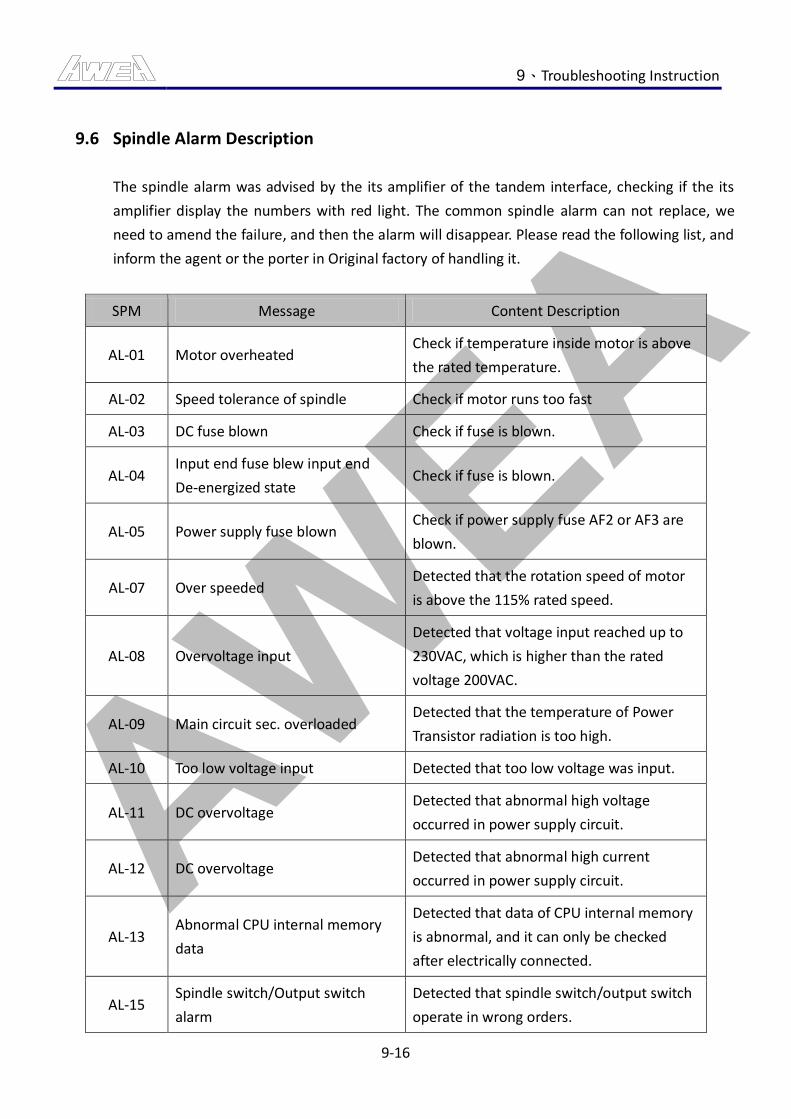
AWEA 9、Troubleshooting Instruction
9-16
9.6 Spindle Alarm Description
The spindle alarm was advised by the its amplifier of the tandem interface, checking if the its
amplifier display the numbers with red light. The common spindle alarm can not replace, we
need to amend the failure, and then the alarm will disappear. Please read the following list, and
inform the agent or the porter in Original factory of handling it.
SPM Message Content Description
AL-01 Motor overheated Check if temperature inside motor is above
the rated temperature.
AL-02 Speed tolerance of spindle Check if motor runs too fast
AL-03 DC fuse blown Check if fuse is blown.
AL-04 Input end fuse blew input end
De-energized state Check if fuse is blown.
AL-05 Power supply fuse blown Check if power supply fuse AF2 or AF3 are
blown.
AL-07 Over speeded Detected that the rotation speed of motor
is above the 115% rated speed.
AL-08 Overvoltage input
Detected that voltage input reached up to
230VAC, which is higher than the rated
voltage 200VAC.
AL-09 Main circuit sec. overloaded Detected that the temperature of Power
Transistor radiation is too high.
AL-10 Too low voltage input Detected that too low voltage was input.
AL-11 DC overvoltage Detected that abnormal high voltage
occurred in power supply circuit.
AL-12 DC overvoltage Detected that abnormal high current
occurred in power supply circuit.
AL-13 Abnormal CPU internal memory
data
Detected that data of CPU internal memory
is abnormal, and it can only be checked
after electrically connected.
AL-15 Spindle switch/Output switch
alarm
Detected that spindle switch/output switch
operate in wrong orders.
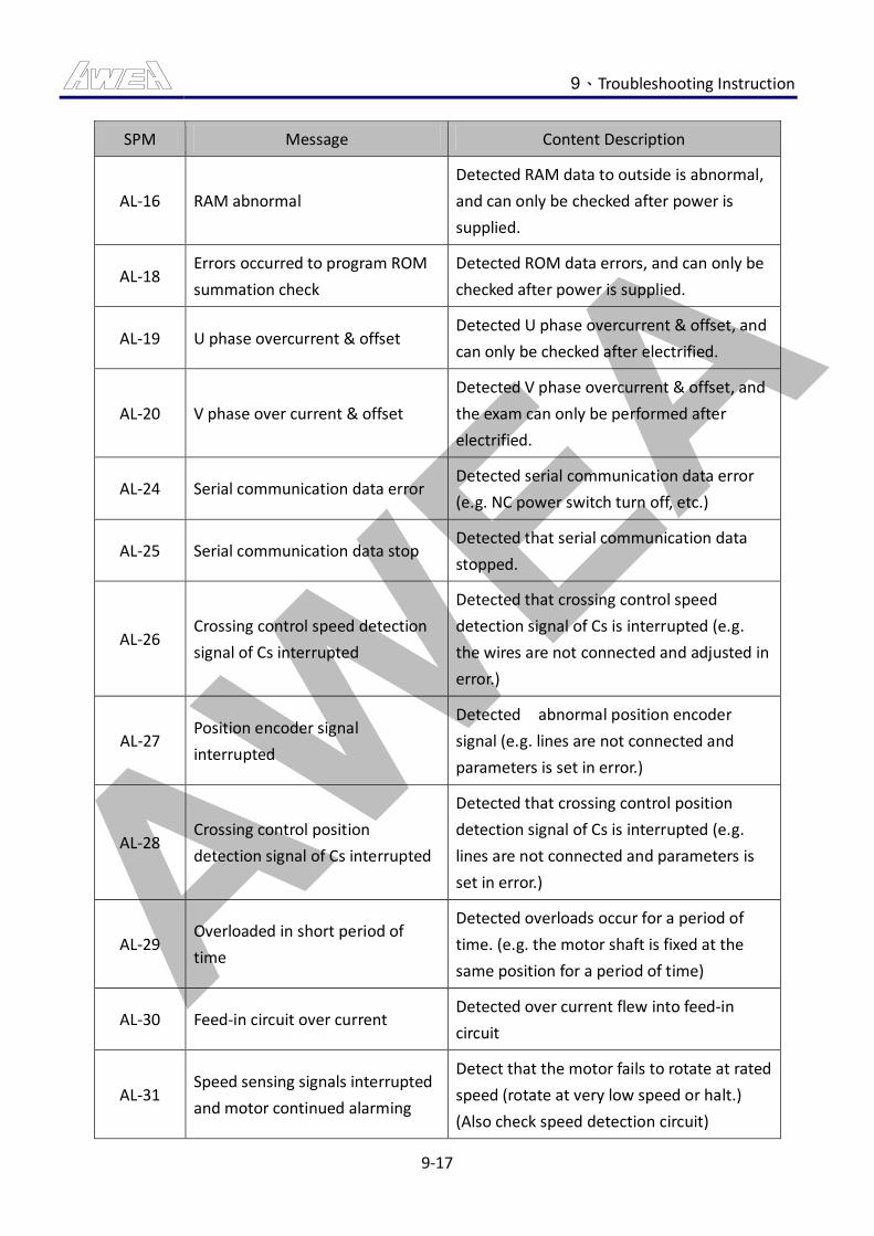
AWEA 9、Troubleshooting Instruction
9-17
SPM Message Content Description
AL-16 RAM abnormal
Detected RAM data to outside is abnormal,
and can only be checked after power is
supplied.
AL-18 Errors occurred to program ROM
summation check
Detected ROM data errors, and can only be
checked after power is supplied.
AL-19 U phase overcurrent & offset Detected U phase overcurrent & offset, and
can only be checked after electrified.
AL-20 V phase over current & offset
Detected V phase overcurrent & offset, and
the exam can only be performed after
electrified.
AL-24 Serial communication data error Detected serial communication data error
(e.g. NC power switch turn off, etc.)
AL-25 Serial communication data stop Detected that serial communication data
stopped.
AL-26 Crossing control speed detection
signal of Cs interrupted
Detected that crossing control speed
detection signal of Cs is interrupted (e.g.
the wires are not connected and adjusted in
error.)
AL-27 Position encoder signal
interrupted
Detected abnormal position encoder
signal (e.g. lines are not connected and
parameters is set in error.)
AL-28 Crossing control position
detection signal of Cs interrupted
Detected that crossing control position
detection signal of Cs is interrupted (e.g.
lines are not connected and parameters is
set in error.)
AL-29 Overloaded in short period of
time
Detected overloads occur for a period of
time. (e.g. the motor shaft is fixed at the
same position for a period of time)
AL-30 Feed-in circuit over current Detected over current flew into feed-in
circuit
AL-31 Speed sensing signals interrupted
and motor continued alarming
Detect that the motor fails to rotate at rated
speed (rotate at very low speed or halt.)
(Also check speed detection circuit)
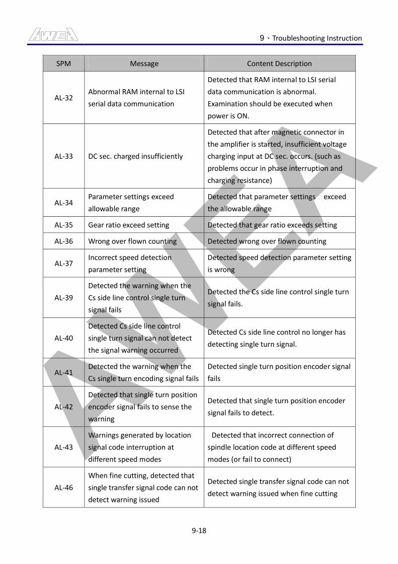
AWEA 9、Troubleshooting Instruction
9-18
SPM Message Content Description
AL-32 Abnormal RAM internal to LSI
serial data communication
Detected that RAM internal to LSI serial
data communication is abnormal.
Examination should be executed when
power is ON.
AL-33 DC sec. charged insufficiently
Detected that after magnetic connector in
the amplifier is started, insufficient voltage
charging input at DC sec. occurs. (such as
problems occur in phase interruption and
charging resistance)
AL-34 Parameter settings exceed
allowable range
Detected that parameter settings exceed
the allowable range
AL-35 Gear ratio exceed setting Detected that gear ratio exceeds setting
AL-36 Wrong over flown counting Detected wrong over flown counting
AL-37 Incorrect speed detection
parameter setting
Detected speed detection parameter setting
is wrong
AL-39
Detected the warning when the
Cs side line control single turn
signal fails
Detected the Cs side line control single turn
signal fails.
AL-40
Detected Cs side line control
single turn signal can not detect
the signal warning occurred
Detected Cs side line control no longer has
detecting single turn signal.
AL-41 Detected the warning when the
Cs single turn encoding signal fails
Detected single turn position encoder signal
fails
AL-42
Detected that single turn position
encoder signal fails to sense the
warning
Detected that single turn position encoder
signal fails to detect.
AL-43
Warnings generated by location
signal code interruption at
different speed modes
Detected that incorrect connection of
spindle location code at different speed
modes (or fail to connect)
AL-46
When fine cutting, detected that
single transfer signal code can not
detect warning issued
Detected single transfer signal code can not
detect warning issued when fine cutting
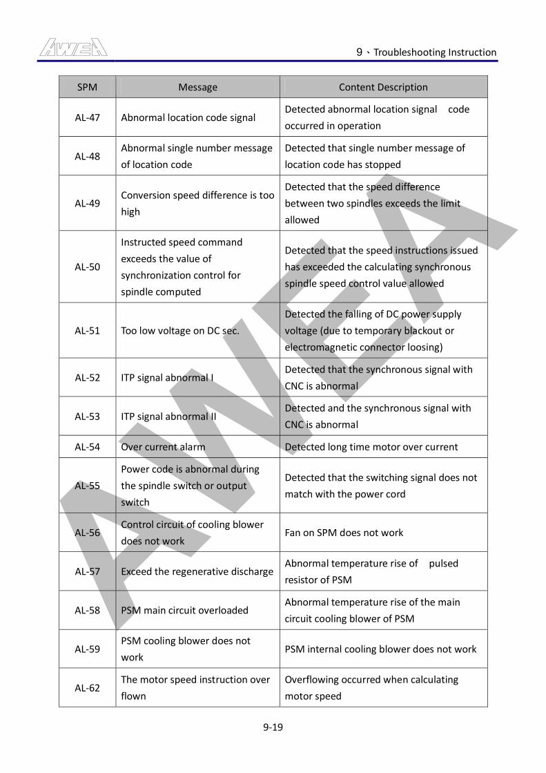
AWEA 9、Troubleshooting Instruction
9-19
SPM Message Content Description
AL-47 Abnormal location code signal Detected abnormal location signal code
occurred in operation
AL-48 Abnormal single number message
of location code
Detected that single number message of
location code has stopped
AL-49 Conversion speed difference is too
high
Detected that the speed difference
between two spindles exceeds the limit
allowed
AL-50
Instructed speed command
exceeds the value of
synchronization control for
spindle computed
Detected that the speed instructions issued
has exceeded the calculating synchronous
spindle speed control value allowed
AL-51 Too low voltage on DC sec.
Detected the falling of DC power supply
voltage (due to temporary blackout or
electromagnetic connector loosing)
AL-52 ITP signal abnormal I Detected that the synchronous signal with
CNC is abnormal
AL-53 ITP signal abnormal II Detected and the synchronous signal with
CNC is abnormal
AL-54 Over current alarm Detected long time motor over current
AL-55
Power code is abnormal during
the spindle switch or output
switch
Detected that the switching signal does not
match with the power cord
AL-56 Control circuit of cooling blower
does not work Fan on SPM does not work
AL-57 Exceed the regenerative discharge Abnormal temperature rise of pulsed
resistor of PSM
AL-58 PSM main circuit overloaded Abnormal temperature rise of the main
circuit cooling blower of PSM
AL-59 PSM cooling blower does not
work PSM internal cooling blower does not work
AL-62 The motor speed instruction over
flown
Overflowing occurred when calculating
motor speed
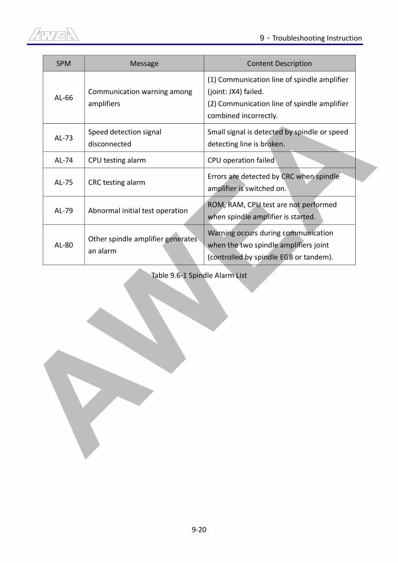
AWEA 9、Troubleshooting Instruction
9-20
SPM Message Content Description
AL-66 Communication warning among
amplifiers
(1) Communication line of spindle amplifier
(joint: JX4) failed.
(2) Communication line of spindle amplifier
combined incorrectly.
AL-73 Speed detection signal
disconnected
Small signal is detected by spindle or speed
detecting line is broken.
AL-74 CPU testing alarm CPU operation failed
AL-75 CRC testing alarm Errors are detected by CRC when spindle
amplifier is switched on.
AL-79 Abnormal initial test operation ROM, RAM, CPU test are not performed
when spindle amplifier is started.
AL-80 Other spindle amplifier generates
an alarm
Warning occurs during communication
when the two spindle amplifiers joint
(controlled by spindle EGB or tandem).
Table 9.6-1 Spindle Alarm List
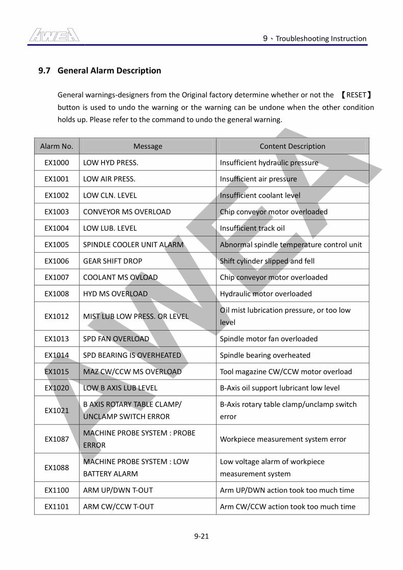
AWEA 9、Troubleshooting Instruction
9-21
9.7 General Alarm Description
General warnings-designers from the Original factory determine whether or not the 【RESET】
button is used to undo the warning or the warning can be undone when the other condition
holds up. Please refer to the command to undo the general warning.
Alarm No. Message Content Description
EX1000 LOW HYD PRESS. Insufficient hydraulic pressure
EX1001 LOW AIR PRESS. Insufficient air pressure
EX1002 LOW CLN. LEVEL Insufficient coolant level
EX1003 CONVEYOR MS OVERLOAD Chip conveyor motor overloaded
EX1004 LOW LUB. LEVEL Insufficient track oil
EX1005 SPINDLE COOLER UNIT ALARM Abnormal spindle temperature control unit
EX1006 GEAR SHIFT DROP Shift cylinder slipped and fell
EX1007 COOLANT MS OVLOAD Chip conveyor motor overloaded
EX1008 HYD MS OVERLOAD Hydraulic motor overloaded
EX1012 MIST LUB LOW PRESS. OR LEVEL Oil mist lubrication pressure, or too low
level
EX1013 SPD FAN OVERLOAD Spindle motor fan overloaded
EX1014 SPD BEARING IS OVERHEATED Spindle bearing overheated
EX1015 MAZ CW/CCW MS OVERLOAD Tool magazine CW/CCW motor overload
EX1020 LOW B AXIS LUB LEVEL B-Axis oil support lubricant low level
EX1021 B AXIS ROTARY TABLE CLAMP/
UNCLAMP SWITCH ERROR
B-Axis rotary table clamp/unclamp switch
error
EX1087 MACHINE PROBE SYSTEM : PROBE
ERROR Workpiece measurement system error
EX1088 MACHINE PROBE SYSTEM : LOW
BATTERY ALARM
Low voltage alarm of workpiece
measurement system
EX1100 ARM UP/DWN T-OUT Arm UP/DWN action took too much time
EX1101 ARM CW/CCW T-OUT Arm CW/CCW action took too much time
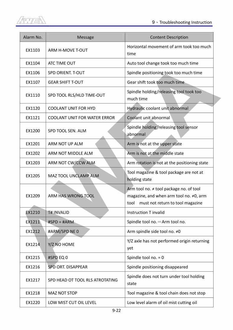
AWEA 9、Troubleshooting Instruction
9-22
Alarm No. Message Content Description
EX1103 ARM H-MOVE T-OUT Horizontal movement of arm took too much
time
EX1104 ATC TIME OUT Auto tool change took too much time
EX1106 SPD ORIENT. T-OUT Spindle positioning took too much time
EX1107 GEAR SHIFT T-OUT Gear shift took too much time
EX1110 SPD TOOL RLS/HLD TIME-OUT Spindle holding/releasing tool took too
much time
EX1120 COOLANT UNIT FOR HYD Hydraulic coolant unit abnormal
EX1121 COOLANT UNIT FOR WATER ERROR Coolant unit abnormal
EX1200 SPD TOOL SEN. ALM Spindle holding/releasing tool sensor
abnormal
EX1201 ARM NOT UP ALM Arm is not at the upper state
EX1202 ARM NOT MIDDLE ALM Arm is not at the middle state
EX1203 ARM NOT CW/CCW ALM Arm rotation is not at the positioning state
EX1205 MAZ TOOL UNCLAMP ALM Tool magazine & tool package are not at
holding state
EX1209 ARM HAS WRONG TOOL
Arm tool no. ≠ tool package no. of tool
magazine, and when arm tool no. ≠0, arm
tool must not return to tool magazine
EX1210 T# INVALID Instruction T invalid
EX1211 #SPD = #ARM Spindle tool no.=Arm tool no.
EX1212 #ARM/SPD NE 0 Arm spindle side tool no. ≠0
EX1214 Y/Z NO HOME Y/Z axle has not performed origin returning
yet
EX1215 #SPD EQ 0 Spindle tool no. = 0
EX1216 SPD ORT. DISAPPEAR Spindle positioning disappeared
EX1217 SPD HEAD OT TOOL RLS ATROTATING Spindle does not turn under tool holding
state
EX1218 MAZ NOT STOP Tool magazine & tool chain does not stop
EX1220 LOW MIST CUT OIL LEVEL Low level alarm of oil mist cutting oil
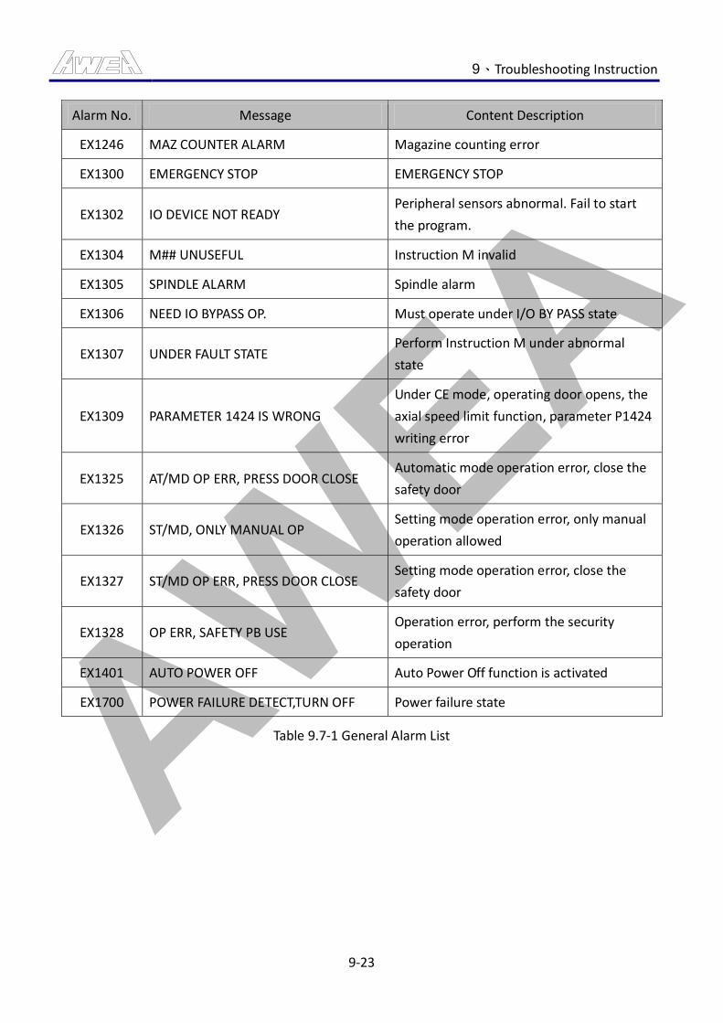
AWEA 9、Troubleshooting Instruction
9-23
Alarm No. Message Content Description
EX1246 MAZ COUNTER ALARM Magazine counting error
EX1300 EMERGENCY STOP EMERGENCY STOP
EX1302 IO DEVICE NOT READY Peripheral sensors abnormal. Fail to start
the program.
EX1304 M## UNUSEFUL Instruction M invalid
EX1305 SPINDLE ALARM Spindle alarm
EX1306 NEED IO BYPASS OP. Must operate under I/O BY PASS state
EX1307 UNDER FAULT STATE Perform Instruction M under abnormal
state
EX1309 PARAMETER 1424 IS WRONG
Under CE mode, operating door opens, the
axial speed limit function, parameter P1424
writing error
EX1325 AT/MD OP ERR, PRESS DOOR CLOSE Automatic mode operation error, close the
safety door
EX1326 ST/MD, ONLY MANUAL OP Setting mode operation error, only manual
operation allowed
EX1327 ST/MD OP ERR, PRESS DOOR CLOSE Setting mode operation error, close the
safety door
EX1328 OP ERR, SAFETY PB USE Operation error, perform the security
operation
EX1401 AUTO POWER OFF Auto Power Off function is activated
EX1700 POWER FAILURE DETECT,TURN OFF Power failure state
Table 9.7-1 General Alarm List
AWEA 9、Troubleshooting Instruction
9-24
9.8 General Alarm Countermeasures Description
The chapter provides users with easy treatment process on warning when it occurs.
CAUTION
1. Power supply, unless in the process of electricity delivery operation, shall be cut off before
the implement of warning undoing.
2. Before undoing the warning, please read the relevant command for operation.
3. Please contact the customer service from the Original factory when the countermeasures
below DO NOT work.
9.8.1 Alarm EX1000【LOW HYD PRESS】
Alarm: LOW HYD PRESS.
Content: Insufficient hydraulic pressure
Countermeasure:
(1) Adjust the hydraulic pressure when it is not enough. Pressure demand for general
hydraulic pressure system is 45kg/cm^2.
(2) Add hydraulic pressure oil when it is not enough in hydraulic pressure tank.
Hydraulic pressure oil must be kept above the low position line.
(3) Replace the broken hydraulic pressure pipe with a new one when oil pipe leaks.
(4) Fix the joint of unclamp hydraulic pipe when it unclamps.
(5) In case that the electromagnetic switch of hydraulic pressure motor fails to
function, please check whether or not the power supply of coil works normally.
Replace the electromagnetic switch if the problem is not caused by the power
supply of coil.
(6) Replace the motor conducting wire when a broken circuit occurs on the motor.
(7) Repair or replace the motor when there is a breakdown on the hydraulic pressure
motor.
(8) Replace the pressure switch or conducting wire when there is a breakdown on
pressure switch.
(9) Relay board is damaged, please maintain or replace the relay board.
AWEA 9、Troubleshooting Instruction
9-25
9.8.2 Alarm EX1001【LOW AIR PRESS】
Alarm: LOW AIR PRESS
Content: Insufficient air pressure
Countermeasure:
(1) When shortage of pressure source occurred, adjust the air pressure. The normal
air pressure required is 5~7kg/cm^2.
(2) Hose broke and leaked, replace damaged pressure pipe.
(3) If hose connection loosed, please fix the loosing pneumatic connector.
(4) Adjust the pressure switch setting when the pressure switch setting has a poor
design. The correct setting pressure switch is 4kg/cm^2.
(5) Pressure switch failed, replace the switch or leading wire.
9.8.3 Alarm EX1002【LOW CLN LEVEL】
Alarm: LOW CLN LEVEL
Content: Insufficient coolant level
Countermeasure:
(1) If the coolant is insufficient, add coolant without level lowering than the low line
of the tank.
(2) Replace the liquid level sensor when there is a breakdown.
(3) Check and repair whether or not the circuit is connected wrong or there is broken
circuit when the conducting wire is broken.
(4) Clean or replace the filter in case of blockage when water is out from the center.
9.8.4 Alarm EX1003【CONVEYOR MS OVERLOAD】
Alarm: CONVEYOR MS OVERLOAD
Content: Chip conveyor motor overloaded
Countermeasure:
(1) Clean the iron chippings if they stuck the chip conveyor belt. After the cleaning,
press the 【RESET】 button on the loading protector.
(2) Eliminate any bad conditions which cause problems to the heat dissipation of
motor such as chippings removal. Press 【RESET】 button on the loading
protector.
AWEA 9、Troubleshooting Instruction
9-26
(3) Short circuit of chip conveyor motor coil, please send the motor for maintenance
and repair or replace the chip conveyor motor. After maintenance or replacement,
press 【RESET】 button on the overload protector to recover.
(4) Check and repair the motor loading loop when a bypass occurs to the conducting
wire.
9.8.5 Alarm EX1004【LOW LUB LEVEL】
Alarm: LOW LUB LEVEL
Content: Insufficient track oil
Countermeasure:
(1) If lubricant is insufficient, add lubricant without lowering than the low line of the
track tank.
(2) If the liquid level switch is damaged, replace it.
(3) Lubricant is enough; however, the signal of liquid level is ignored.
Self-preservation relay shall be set 0.
9.8.6 Alarm EX1005【SPINDLE COOLER UNIT ALARM】
Alarm: SPINDLE COOLER UNIT ALARM
Content: Abnormal spindle temperature control unit
Countermeasure:
(1) Increase pressure when it is not enough. General standard for pressure shall be
above 4kg/cm^2.
(2) If spindle lubricant is insufficient, add lubricant without lowering than the low
line on the spindle head.
(3) Implement the breakdown elimination function by referring to the spindle
temperature controller manual or inquire the supplier of spindle temperature
controller when spindle temperature controller warning functions.
(4) Check and repair the relevant circuit when conducting wire is damaged.
AWEA 9、Troubleshooting Instruction
9-27
9.8.7 Alarm EX1006【GEAR SHIFT DROP】
Alarm: GEAR SHIFT DROP
Content: Shift cylinder slipped and fell
Countermeasure:
(1) The high and low oil pressure is insufficient, improve the shift cylinder oil
pressure, and the general oil pressure system is 10kg/cm^2.
(2) Replace the high/low gear electromagnetic valves when they are damaged.
(3) Adjust the sensor to the correct position when the high/low gear detector is not
placed right.
(4) Replace the sensor when the high/low gear detector is damaged.
(5) Leading wire is disconnected, please maintain the related circuits.
(6) Relay board is damaged, please maintain or replace the relay board.
9.8.8 Alarm EX1007【COOLANT MS OVERLOAD】
Alarm: COOLANT MS OVERLOAD
Content: Chip conveyor motor overloaded
Countermeasure:
(1) Inefficient coolant motor cooling, after inefficient objects troubleshooting, press
【RESET】button on the overload protector to recover.
(2) Short circuit of chip conveyor motor coil, please send the motor to the
manufacturer for maintenance and repair or replace it with a new one. After
maintenance or replacement, press 【RESET】 button on the overload protector
to recover.
(3) Overload protector is damaged, replace the overload protector.
(4) Leading wire bypassed, please maintain the overloading related circuits.
9.8.9 Alarm EX1008【HYD MS OVERLOAD】
Alarm: HYD MS OVERLOAD
Content: Hydraulic motor overloaded
Countermeasure:
(1) Clean the filter screen in the hydraulic pressure tank when it is clogged. Press the
【RESET】 button on the overloading protection to restore.
AWEA 9、Troubleshooting Instruction
9-28
(2) Oil pressure of hydraulic tank is insufficient; please add hydraulic oil. After the
supplement is completed, press 【RESET】 button of the overload protector to
recover.
(3) Short circuit of hydraulic motor coil occurred, please send the motor to the
manufacturer for maintenance and repair or replace it with a new one. After
maintenance or replacement, press 【RESET】 button on the overload protector
to recover.
(4) Overload protector is damaged, replace the overload protector.
(5) Leading wire bypassed, please maintain the related overload circuits.
9.8.10 Alarm EX1012【MIST LUB PRESS OR LEVEL】
Alarm: MIST LUB PRESS OR LEVEL
Content: Oil mist lubrication pressure, or too low level
Countermeasure:
(1) Oil mist lubricating pressure is insufficient. Adjust the pressure.
(2) If oil mist lubricant is insufficient, add lubricant without lowering than the low
line of the oil Hydraulic lubrication tank.
(3) Replace the oil mist lubricator with a new one when the sensor is damaged.
(4) Relay board is damaged, please maintain or replace the relay board.
9.8.11 Alarm EX1013【SPD FAN OVERLOAD】
Alarm: SPD FAN OVERLOAD
Content: Spindle motor fan overloaded
Countermeasure:
(1) Spindle motor air outlet is blocked. After excluded the blocked situation, press
【RESET】button on the overload protector to recover.
(2) Spindle motor blower is stuck; please send the spindle motor blower to
manufacturer for maintenance or replacement. After maintenance or
replacement, press 【RESET】 button on the overload protector to recover.
(3) Overload protector is damaged, replace the overload protector.
(4) Leading wire bypassed, please maintain the related overload circuits.
AWEA 9、Troubleshooting Instruction
9-29
9.8.12 Alarm EX1014【SPD BEARING IS OVERHEATED】
Alarm: SPD BEARING IS OVERHEATED
Content: Spindle bearing overheated
Countermeasure:
(1) Stop the operation of the machine, and check if the spindle cooler is abnormal.
(2) Temperature sensor is damaged. Replace the temperature sensor.
(3) Temperature card is damaged. Replace the temperature card.
(4) Variable resistance value can be adjusted when there is a problem with
temperature comparison card resistance adjustment.
(5) I/O Card is damaged. Replace the I/O Card.
(6) Relay board is damaged, please replace the relay board.
9.8.13 Alarm EX1015【MAZ CW/CCW MS OVERLOAD】
Alarm: MAZ CW/CCW MS OVERLOAD
Content: Tool magazine CW/CCW motor overload
Countermeasure:
(1) MAZ rotation mechanism stuck. Please maintain the related MAZ mechanism.
After maintenance or replacement, press 【RESET】 button on the overload
protector to recover.
(2) Short circuit of tool magazine CW/CCW motor coil, please send the motor for
maintenance and repair or replace the tool magazine CW/CCW motor. After
maintenance or replacement, press 【RESET】 button on the overload protector
to recover.
(3) Leading wire bypassed, please maintain the related overload circuits.
9.8.14 Alarm EX1020【LOW B AXIS LUB LEVEL】
Alarm: LOW B AXIS LUB LEVEL
Content: B-Axis oil support lubricant low level
Countermeasure:
(1) If B-Axis oil support lubricant is insufficient, add lubricant without lowering than
the low line of the track tank.
(2) If the liquid level switch is damaged, replace it.
AWEA 9、Troubleshooting Instruction
9-30
9.8.15 Alarm EX1021【B AXIS ROTARY TABLE CLAMP/UNCLAMP SWITCH ERROR】
Alarm: B AXIS ROTARY TABLE CLAMP/UNCLAMP SWITCH ERROR
Content: B-Axis rotary table clamp/unclamp switch error
Countermeasure:
(1) Reset the checking time for B-Axis rotary table clamp/unclamp.
(2) B-Axis rotary table clamp/unclamp sensor is damaged. Please replace the B-Axis
rotary table clamp/unclamp sensor.
(3) Leading wire bypassed, please maintain the related circuits.
9.8.16 Alarm EX1087【MACHINE PROBE SYSTEM: PROBE ERROR】
Alarm: MACHINE PROBE SYSTEM: PROBE ERROR
Content: Workpiece measurement system error
Countermeasure:
(1) Adjust the position or angle of the receiver and then press the 【RESET】 button
on the panel to restart the command if the receiver fails to receive any order.
(2) Install the signal transmitter on the spindle head and then press the 【RESET】
button on the panel to restart the command if the signal transmitter is not placed
on the spindle head.
(3) Signal generator is disconnected. Replace battery and press 【RESET】 button on
the panel and re-perform the start command.
(4) Refer to the regulation for setting on OEM service manual if the setting for signal
transmitter junction point is wrong.
(5) Leading wire bypassed, please maintain the related circuits.
9.8.17 Alarm EX1088【MACHINE PROBE SYSTEM: LOW BATTERY ALARM】
Alarm: MACHINE PROBE SYSTEM: LOW BATTERY ALARM
Content: Low voltage alarm of workpiece measurement system
Countermeasure:
(1) Signal generator is disconnected. Replace battery and press 【RESET】 button on
the panel and re-perform the start command.
(2) Signal generator setting error. Please refer to the service manual setting of
manufacturer.
(3) Leading wire bypassed, please maintain the related circuits.

AWEA 9、Troubleshooting Instruction
9-31
9.8.18 Alarm EX1100【ARM UP/DOWN T-OUT】
Alarm: ARM UP/DOWN T-OUT
Content: Arm UP/DWN action took too much time
Countermeasure:
(1) Reset the checking time for tool ascent/ descent.
(2) Replace the tool ascent/descent sensor if there is a damage.
(3) Arm Up/Down Sensor detects distance and position are incorrect. Please adjust
the arm Up/Down position or distance of sensor.
(4) Check and replace the tool ascent/descent hydraulic pressure tank if there is a
leakage inside the tank.
(5) Hydraulic piping connected wrong. Recheck the hydraulic piping.
(6) Check and replace the tool change device if there is a clogging.
(7) Oil pressure is insufficient. Adjust the oil pressure.
(8) Hydraulic solenoid valve is damaged. Please maintain or replace the hydraulic
solenoid valve.
(9) Relay board is damaged, please maintain or replace the relay board.
(10) Leading wire bypassed, please maintain the related circuits.
9.8.19 Alarm EX1101【ARM CW/CCW T-OUT】
Alarm: ARM CW/CCW T-OUT
Content: Arm CW/CCW action took too much time
Countermeasure:
(1) Reset the Arm CW/ CCW checking time.
(2) Arm CW/ CCW sensor is damaged. Please replace the Arm CW/ CCW sensor.
(3) Arm CW/CCW sensor detected distance and position are incorrect. Please adjust
the position or distance of Arm CW/CCW sensor.
(4) Internal leakage of arm CW/ CCW hydraulic cylinder occurred. Please maintain
and repair the Arm CW/ CCW hydraulic cylinder.
(5) Pressure is insufficient. Adjust the air pressure.
(6) The ARM Mechanism stuck. Overhaul the ARM Mechanism.
(7) Oil pressure is insufficient. Adjust the oil pressure.
(8) Hydraulic solenoid valve is damaged. Please maintain or replace the hydraulic
solenoid valve.
AWEA 9、Troubleshooting Instruction
9-32
(9) Relay board is damaged, please maintain or replace the relay board.
(10) Leading wire bypassed, please maintain the related circuits.
9.8.20 Alarm EX1103【ARM H-MOVE T-OUT】
Alarm: ARM H-MOVE T-OUT
Content: Horizontal movement of arm took too much time
Countermeasure:
(1) Reset the checking time of Arm horizontal movement.
(2) Arm horizontal movement limit switch is damaged. Replace the Arm horizontal
movement limit switch.
(3) The Tool Change Door horizontal movement limit switch detects distance and
position incorrect. Adjust the Tool Change Door horizontal movement limit
switch position or distance.
(4) Leakage found in pneumatic cylinder for horizontal movement of arm. Repair
pneumatic cylinder for horizontal movement of arm.
(5) Leakage found in hydraulic cylinder for horizontal movement of arm. Repair
hydraulic cylinder for horizontal movement of arm.
(6) Recheck the air pipes if there is a mistake in the connection.
(7) Hydraulic piping connected wrong. Recheck the hydraulic piping.
(8) The ARM Mechanism stuck. Overhaul the ARM Mechanism.
(9) Pressure is insufficient. Adjusting the air pressure.
(10) Pressure solenoid valve is damaged. Repair or replace the pressure solenoid
valve.
(11) Oil pressure is insufficient. Adjust the oil pressure.
(12) Hydraulic solenoid valve is damaged. Please maintain or replace the hydraulic
solenoid valve.
(13) Relay board is damaged, please maintain or replace the relay board.
(14) Leading wire bypassed, please maintain the related circuits.
9.8.21 Alarm EX1104【ATC TIME OUT】
Alarm: ATC TIME OUT
Content: Auto tool change took too much time
Countermeasure:
(1) Resetting the checking time of Auto Tool Change.
AWEA 9、Troubleshooting Instruction
9-33
9.8.22 Alarm EX1106【SPD ORIENT T-OUT】
Alarm: SPD ORIENT T-OUT
Content: Spindle positioning took too much time
Countermeasure:
(1) Resetting the checking time of spindle positioning.
(2) Error occurred in the parameter settings for spindle positioning, fix the
parameter for spindle positioning.
(3) Refer to the FANUC parameter manual to have the parameter for spindle
positioning.
(4) The gap between the spindle positioning sensor and the sensing-block is not
correct. Adjust the distance of the sensing-block or the distance of the sensor.
(5) The cable connector to the spindle decoder is not connected, please lock the
cable connector tight.
(6) Spindle encoder cable disconnected, replace the cable.
(7) The spindle driver is not under normal condition, replace the spindle driver.
(8) The spindle transmission mechanism is not under normal condition, please check
the spindle transmission mechanism.
9.8.23 Alarm EX1107【GEAR SHIFT T-OUT】
Alarm: GEAR SHIFT T-OUT.
Content: Gear shift took too much time
Countermeasure:
(1) Resetting the checking time of gearshift action.
(2) The high and low for sensor location is not installed correctly, adjust the sensor
sensing the location.
(3) Spindle shift parameter setting errors, amendments to the spindle shift
parameters.
(4) “Spindle shift parameters, refer to FANUC parameter manual”
(5) The hydraulic cylinder of gear change is leaking inside, please examine and repair
the hydraulic cylinder of gear change.
(6) Shift hydraulic pipes connected wrong. Recheck the hydraulic pipes.
(7) The high/low range signals are broken off, please replace the sensor or examine
and repair the related circuits.
(8) Hydraulic pressure, adjusting the hydraulic pressure.
AWEA 9、Troubleshooting Instruction
9-34
(9) Hydraulic solenoid valve is damaged. Please maintain or replace the hydraulic
solenoid valve.
(10) Relay board is damaged, please maintain or replace the relay board.
9.8.24 Alarm EX1110【SPD TOOL RLS/HLD TIME OUT】
Alarm: SPD TOOL RLS/HLD TIME OUT
Content: Spindle holding/releasing tool took too much time
Countermeasure:
(1) Reset the spindle to grab the loose knife action to check the time.
(2) Spindle loose knife to the sensor location is not installed correctly, adjust the
sensor sensing location.
(3) Spindle loose knife hydraulic cylinder leak. Repair the Spindle loose knife
hydraulic cylinder.
(4) Spindle Pine knife hydraulic pipes are wrong. Recheck the hydraulic pipes.
(5) Spindle Pine knife signal is interrupted, replace the sensor or
maintenance-related circuits.
(6) Hydraulic pressure, adjusting the hydraulic pressure.
(7) Hydraulic solenoid valve is damaged. Please maintain or replace the hydraulic
solenoid valve.
(8) Relay board is damaged, please maintain or replace the relay board.
9.8.25 Alarm EX1120【COOLANT UNIT FOR HYD】
Alarm: COOLANT UNIT FOR HYD
Content: Hydraulic coolant unit abnormal
Countermeasure:
(1) Overhaul the relevant circuit to see if it is connected I error or disconnection.
(2) Perform troubleshooting according to the maintenance manual or send an
inquiry to the company.
9.8.26 Alarm EX1121【COOLANT UNIT FOR HYD】
Alarm: COOLANT UNIT FOR HYD
Content: Coolant unit abnormal
Countermeasure:
(1) Overhaul the relevant circuit to see if it is connected I error or disconnection.
AWEA 9、Troubleshooting Instruction
9-35
(2) Perform troubleshooting according to the maintenance manual or send an
inquiry to the company.
9.8.27 Alarm EX1200【SPD TOOL SEN ALM】
Alarm: SPD TOOL SEN ALM
Content: Spindle holding/releasing tool sensor abnormal
Countermeasure:
(1) Spindle Pine knife sensor installation location is incorrect, adjust the sensor
sensing the location and distance.
(2) The clamping/unclamp sensor of the spindle is damaged, examine and repair the
sensor or replace it.
(3) Signal short-circuit caused by the maintenance-related circuits.
9.8.28 Alarm EX1201【ARM NOT UP ALM】
Alarm: ARM NOT UP ALM
Content: Arm is not at the upper state
Countermeasure:
(1) Operate the tool magazine manually to move it upon the tool-changing arm.
(2) Arm sensor is damaged. Repair or replace the sensor.
(3) The arm sensor installation location is incorrect, adjust the sensor sensing the
position and distance.
(4) Signal short-circuit caused by the maintenance-related circuits.
9.8.29 Alarm EX1202【ARM NOT MIDDLE ALM】
Alarm: ARM NOT MIDDLE ALM
Content: Arm is not at the middle state
Countermeasure:
(1) Manually operated action of the tool magazine to the arm position.
(2) Arm limit switch is damaged. Repair or replace the limit switch.
(3) Arm-bit limit switch mounting location is incorrect, adjust the limit switch
position and distance.
(4) Signal short-circuit caused by the maintenance-related circuits.
AWEA 9、Troubleshooting Instruction
9-36
9.8.30 Alarm EX1203【ARM NOT CW/CCW ALM】
Alarm: ARM NOT CW/CCW ALM
Content: Arm rotation is not at the positioning state
Countermeasure:
(1) Rotation of the manually operated action of the tool magazine to the arm
positioning.
(2) The arm rotation sensor is damaged. Repair or replacement of sensors.
(3) Arm rotation sensor installation location is incorrect, adjust the sensor sensing
the position and distance.
(4) Signal short-circuit caused by the maintenance-related circuits.
9.8.31 Alarm EX1205【MAZ TOOL UNCLAMP ALM】
Alarm: MAZ TOOL UNCLAMP ALM
Content: Tool magazine & tool package are not at holding state
Countermeasure:
(1) Manually operated knife library movement to the tool magazine pocket grasping.
(2) Tool storage pocket sensor is damaged. Repair or replacement of sensors.
(3) Tool magazine pocket sensor installation location is incorrect, adjust the sensor
sensing the position and distance.
(4) Signal short-circuit caused by the maintenance-related circuits.
9.8.32 Alarm EX1209【ARM HAS WRONG TOOL】
Alarm: ARM HAS WRONG TOOL
Content: Arm tool no. ≠ tool package no. of tool magazine, and when arm tool no. ≠0, arm
tool must not return to tool magazine
Countermeasure:
(1) Operation error detected, press 【RESET】 button to clear the alarm.
(2) Manually operating the tool magazine rotation, making the knife arm knife =
knife libraries knife number.
(3) Check the status of the arm number, and perform the tool no. modification.
(4) Remove the tool on the arm, and perform the tool no. modification to remove
the arm number.
AWEA 9、Troubleshooting Instruction
9-37
9.8.33 Alarm EX1210【T#INVALID】
Alarm: T#INVALID
Content: Instruction T invalid
Countermeasure:
(1) The capacity setting of the tool magazine is not correct, perform the self-holding
relay after checking the total capacity of the tool magazine.
(2) When the T command exceeds the maximum capacity of the tool magazine while
executing the tool no. modification, press the 【RESET】 button to clear the alarm,
then perform tool no. modification command again.
9.8.34 Alarm EX1211【#SPD=#ARM】
Alarm: #SPD=#ARM
Content: Spindle tool no.=Arm tool no.
Countermeasure:
(1) When performing alternation of tool no., if the spindle tool no. equals to the arm
tool no., press the function key 【RESET】to clear the alarm, and then re-run the
Tool No. Alter Command.
9.8.35 Alarm EX1212【#ARM/SPD NE 0】
Alarm: #ARM/SPD NE 0
Content: Arm spindle side tool no. ≠0
Countermeasure:
(1) Modify DATA TABLE, D6=0.
(2) Operate the tool-changing arm to rotate manually, perform the tool no.
modification, and clear the tool-changing arm number to restore the status of the
tool-changing arm.
AWEA 9、Troubleshooting Instruction
9-38
9.8.36 Alarm EX1214【ATC NOT READY】
Alarm: ATC NOT READY
Content: Y/Z axle has not performed origin returning yet
Countermeasure:
(1) When axes Y and Z are not returning back to the HOME before executing auto
tool change, perform the command to make axes Y and Z Home Return the
HOME.
9.8.37 Alarm EX1215【SPD EQ 0】
Alarm: SPD EQ 0
Content: Spindle tool no. = 0
Countermeasure:
(1) When executing manual unclamp, the tool no. of the spindle can not be zero.
When modifying the tool no. of the spindle, the average standard tool no. of the
main axis can not be zero.
9.8.38 Alarm EX1216【SPD ORT DISAPPEAR】
Alarm: SPD ORT DISAPPEAR
Content: Spindle positioning disappeared
Countermeasure:
(1) When the spindle positioning is gone while executing auto tool change, increase
the value of P4075 parameter to intensify the holding power of spindle
positioning.
Refer to the FANUC parameter manual to have the parameter for spindle
positioning.
(2) Significant error occurred in the rotation-positioning position of the
tool-changing arm, please readjust the rotation-positioning position of the
tool-changing arm.
(3) Set the value of parameter P4016#7 as 1.
Refer to the FANUC parameter manual to have the parameter for spindle
positioning.
AWEA 9、Troubleshooting Instruction
9-39
9.8.39 Alarm EX1217【SPD HEAD OT TOOL RLS AT ROTATING】
Alarm: SPD HEAD OT TOOL RLS AT ROTATING
Content: Spindle does not turn under tool holding state
Countermeasure:
(1) Error occurred in the position of the spindle unclamp sensor, adjust the position
of the spindle unclamp sensor.
(2) Spindle tool release sensor is damaged. Replace the spindle tool release sensor.
(3) Leading wire bypassed, please maintain the related circuits.
9.8.40 Alarm EX1218【MAZ NOT STOP】
Alarm: MAZ NOT STOP
Content: Tool magazine & tool chain does not stop
Countermeasure:
(1) Abnormal tool counting sensor position. Adjust the tool counting sensor position.
(2) Tool counting sensor damaged. Replace the sensor.
(3) Leading wire bypassed, please maintain the related circuits.
9.8.41 Alarm EX1220【MIST ALARM】
Alarm: LOW MIST CUT OIL LEVEL
Content: Low level alarm of oil mist cutting oil
Countermeasure:
(1) If oil mist lubricant is insufficient, add lubricant without lowering than the low
line of the oil mist lubrication tank.
(2) Level switch is damaged. Please repair or replace the liquid level switch.
9.8.42 Alarm EX1246【MAZ COUNTER ALARM】
Alarm: MAZ COUNTER ALARM
Content: Magazine counting error
Countermeasure:
(1) Abnormal tool counting sensor position. Adjust the tool counting sensor position.
(2) Tool counting sensor damaged. Replace the sensor.
AWEA 9、Troubleshooting Instruction
9-40
(3) Leading wire bypassed, please maintain the related circuits.
(4) MAZ mechanism stuck. Please maintain the related MAZ mechanism.
9.8.43 Alarm EX1300【EMERGENCY STOP】
Alarm: EMERGENCY STOP
Content: EMERGENCY STOP
Countermeasure:
(1) When the emergency stop showed up automatically while starting, press the
【SERVO ON】button.
(2) Under the open condition of the operation door, shut the operation door and
press the 【SERVO ON】button.
(3) Emergency stop button has been triggered, please check the emergency stop
buttons of every position, and release the button that has been triggered.
(4) The axial value has exceeded the range limit, press the 【O.T.REL】 button and
uses the manual pulse generator to move away from the OT position.
(5) Error occurred in the emergency stop circuits, examine and repair the related
circuits and equipments.
9.8.44 Alarm EX1302【IO DEVICE NOT READY】
Alarm: IO DEVICE NOT READY
Content: Peripheral sensors abnormal. Fail to start the program.
Countermeasure:
(1) Check the hydraulic pressure to see if it is under normal condition.
(2) Check if the air pressure is normal.
(3) Check if the coolant level is normal.
(4) Check if track oil level is normal.
(5) Check if the spindle cooler is normal.
(6) Check the peripheral motor to see if it is overloaded.
9.8.45 Alarm EX1304【M## UNUSEFUL】
Alarm: M## UNUSEFUL
Content: Instruction M invalid
Countermeasure:
(1) The M command is an optional function, please buy the optional function
AWEA 9、Troubleshooting Instruction
9-41
9.8.46 Alarm EX1305【SPINDLE ALARM】
Alarm: SPINDLE ALARM
Content: Spindle alarm
Countermeasure:
(1) Perform problem resolution according to the error message and FANUC
maintenance manual.
9.8.47 Alarm EX1306【NEED IO BYPASS OP】
Alarm: NEED IO BYPASS OP
Content: Must operate under I/O BY PASS state
Countermeasure:
(1) The M command can only be used under the execution of I/O BY PASS mode.
“Use while it is under adjustment and maintenance.”
9.8.48 Alarm EX1307【UNDER FAULT STATE】
Alarm: UNDER FAULT STATE
Content: Perform Instruction M under abnormal state
Countermeasure:
(1) When using the M command to perform the mechanism movement, the
execution conditions need to be conformed.
9.8.49 Alarm EX1309【PARAMETER 1424 IS WRONG】
Alarm: PARAMETER 1424 IS WRONG
Content: Under CE mode, operating door opens, the axial speed limit function, parameter
P1424 writing error
Countermeasure:
(1) Operation error. Press function button 【RESET】for alarm cleaning action.
(2) Check the total amount of the software control axes to see if it is correct, if not,
replace the controller with correct axes amount.
AWEA 9、Troubleshooting Instruction
9-42
9.8.50 Alarm EX1325【AT/MD OP ERR, PRESS DOOR CLOSE】
Alarm: AT/MD OP ERR, PRESS DOOR CLOSE
Content: Automatic mode operation error, close the safety door
Countermeasure:
(1) When the Enable Operation mode is under auto mode, and the safety door is
open, the execution of programming circular motion is forbidden. If it is
necessary to perform the programming circular motion, please shut the safety
door.
9.8.51 Alarm EX1326【ST/MD, ONLY MANUAL OP】
Alarm: ST/MD, ONLY MANUAL OP
Content: Setting mode operation error, only manual operation allowed
Countermeasure:
(1) When the Enable Operation Mode is under setting mode, whether the safety
door is open or closed, NEVER perform memo mode processing. If the processing
is required please switch the enable operation mode to auto mode.
9.8.52 Alarm EX1327【ST/MD OP ERR, PRESS DOOR CLOSE】
Alarm: ST/MD OP ERR, PRESS DOOR CLOSE
Content: Setting mode operation error, close the safety door
Countermeasure:
(1) When the Enable Operation Mode is under setting mode and the safety door is
open, if the manual operation is required for the following function: coolant,
spindle positioning, and MAG manual operation, then please close the safety
door.
AWEA 9、Troubleshooting Instruction
9-43
9.8.53 Alarm EX1328【OP ERR, SAFETY PB USE】
Alarm: OP ERR, SAFETY PB USE
Content: Operation error, perform the security operation
Countermeasure:
(1) When the Enable Operation Mode is under auto mode and the safety door is
open, if the manual operation is required for the following function: chip
conveyor, spindle rotation, and axial move, then 【SAFETY OPERATION BUTTON】
must be performed.
9.8.54 Alarm EX1401【AUTO POWER OFF】
Alarm: AUTO POWER OFF
Content: Auto Power Off function is activated
Countermeasure:
(1) Please re-start the machine.
(2) Cancel auto shutdown function.
9.8.55 Alarm EX1700【POWER FAILURE DETECT TURN OFF】
Alarm: POWER FAILURE DETECT TURN OFF
Content: Power failure state
Countermeasure:
(1) If this alarm occurred, please reboot the machine
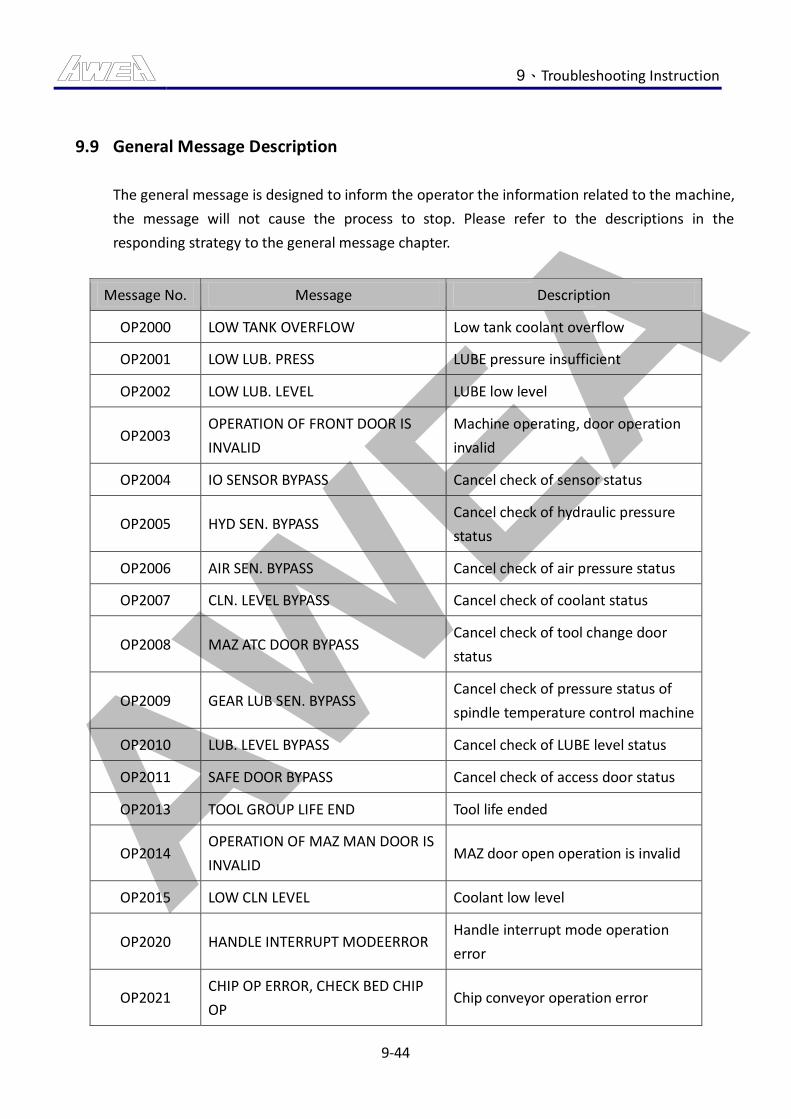
AWEA 9、Troubleshooting Instruction
9-44
9.9 General Message Description
The general message is designed to inform the operator the information related to the machine,
the message will not cause the process to stop. Please refer to the descriptions in the
responding strategy to the general message chapter.
Message No. Message Description
OP2000 LOW TANK OVERFLOW Low tank coolant overflow
OP2001 LOW LUB. PRESS LUBE pressure insufficient
OP2002 LOW LUB. LEVEL LUBE low level
OP2003 OPERATION OF FRONT DOOR IS
INVALID
Machine operating, door operation
invalid
OP2004 IO SENSOR BYPASS Cancel check of sensor status
OP2005 HYD SEN. BYPASS Cancel check of hydraulic pressure
status
OP2006 AIR SEN. BYPASS Cancel check of air pressure status
OP2007 CLN. LEVEL BYPASS Cancel check of coolant status
OP2008 MAZ ATC DOOR BYPASS Cancel check of tool change door
status
OP2009 GEAR LUB SEN. BYPASS Cancel check of pressure status of
spindle temperature control machine
OP2010 LUB. LEVEL BYPASS Cancel check of LUBE level status
OP2011 SAFE DOOR BYPASS Cancel check of access door status
OP2013 TOOL GROUP LIFE END Tool life ended
OP2014 OPERATION OF MAZ MAN DOOR IS
INVALID MAZ door open operation is invalid
OP2015 LOW CLN LEVEL Coolant low level
OP2020 HANDLE INTERRUPT MODEERROR Handle interrupt mode operation
error
OP2021 CHIP OP ERROR, CHECK BED CHIP
OP Chip conveyor operation error

AWEA 9、Troubleshooting Instruction
9-45
Message No. Message Description
OP2022 ATC TOOL CHECK ERROR Tool check error
OP2023 HEAD CLAMP LS BYPASS Cancel check of HEAD clamp status
OP2024 OP ERROR, CHECK BED OP
PANEL ENABLE KEY Operator panel operation error
OP2026 SPINDLE OVERLOAD Spindle load value set
OP2028 SPINDLE OVER SPEED Spindle speed is over
OP2030 MAZ DOOR OPEN MAZ door is in open state.
OP2031 MAZ DOOR CLOSE STATE MAZ door is close
OP2032 MAZ OPERATION MAZ in under manual operation
OP2035 LOW MIST CUT OIL LEVEL Oil mist coolant level is over-low
OP2036 CTS FILTER PRESSURE IS INVALID Coolant through spindle filter is in
stuck state
OP2037 FILTER PRESSURE IS INVALID High tank filter stuck
OP2038 LOW AIR PRESSURE Air pressure lower
OP2060 MAZ ARM ROTATION OPERROR ARM rotation operation error
OP2061 MAZ ROTATION OP ERROR Tool magazine rotation operation
error
OP2062 MAZ ARM UP/DWN OP ERROR ARM UP/DWN operation error
OP2063 MAZ ARM H-MOVE OP ERROR ARM move operation error
OP2069 CALL TOOL ERROR Tool call operation error
OP2070 ATC MAINTENANCE MODE USE Tool Change maintenance mode
is using
OP2080 LOW B AXIS LUB LEVEL B-Axis oil support LUBE low level
Table 9.9-1 General Message List
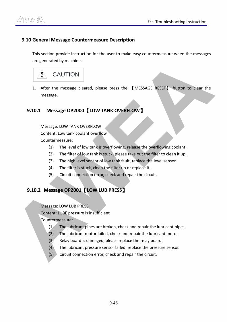
AWEA 9、Troubleshooting Instruction
9-46
9.10 General Message Countermeasure Description
This section provide Instruction for the user to make easy countermeasure when the messages
are generated by machine.
CAUTION
1. After the message cleared, please press the 【MESSAGE RESET】 button to clear the
message.
9.10.1 Message OP2000【LOW TANK OVERFLOW】
Message: LOW TANK OVERFLOW
Content: Low tank coolant overflow
Countermeasure:
(1) The level of low tank is overflowing, release the overflowing coolant.
(2) The filter of low tank is stuck, please take out the filter to clean it up.
(3) The high level sensor of low tank fault, replace the level sensor.
(4) The filter is stuck, clean the filter up or replace it.
(5) Circuit connection error, check and repair the circuit.
9.10.2 Message OP2001【LOW LUB PRESS】
Message: LOW LUB PRESS
Content: LUBE pressure is insufficient
Countermeasure:
(1) The lubricant pipes are broken, check and repair the lubricant pipes.
(2) The lubricant motor failed, check and repair the lubricant motor.
(3) Relay board is damaged, please replace the relay board.
(4) The lubricant pressure sensor failed, replace the pressure sensor.
(5) Circuit connection error, check and repair the circuit.
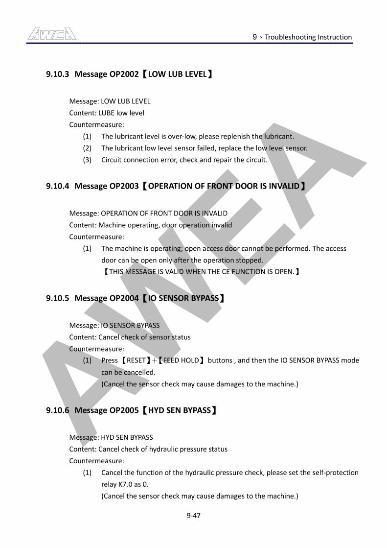
AWEA 9、Troubleshooting Instruction
9-47
9.10.3 Message OP2002【LOW LUB LEVEL】
Message: LOW LUB LEVEL
Content: LUBE low level
Countermeasure:
(1) The lubricant level is over-low, please replenish the lubricant.
(2) The lubricant low level sensor failed, replace the low level sensor.
(3) Circuit connection error, check and repair the circuit.
9.10.4 Message OP2003【OPERATION OF FRONT DOOR IS INVALID】
Message: OPERATION OF FRONT DOOR IS INVALID
Content: Machine operating, door operation invalid
Countermeasure:
(1) The machine is operating; open access door cannot be performed. The access
door can be open only after the operation stopped.
【THIS MESSAGE IS VALID WHEN THE CE FUNCTION IS OPEN.】
9.10.5 Message OP2004【IO SENSOR BYPASS】
Message: IO SENSOR BYPASS
Content: Cancel check of sensor status
Countermeasure:
(1) Press 【RESET】+【FEED HOLD】 buttons , and then the IO SENSOR BYPASS mode
can be cancelled.
(Cancel the sensor check may cause damages to the machine.)
9.10.6 Message OP2005【HYD SEN BYPASS】
Message: HYD SEN BYPASS
Content: Cancel check of hydraulic pressure status
Countermeasure:
(1) Cancel the function of the hydraulic pressure check, please set the self-protection
relay K7.0 as 0.
(Cancel the sensor check may cause damages to the machine.)
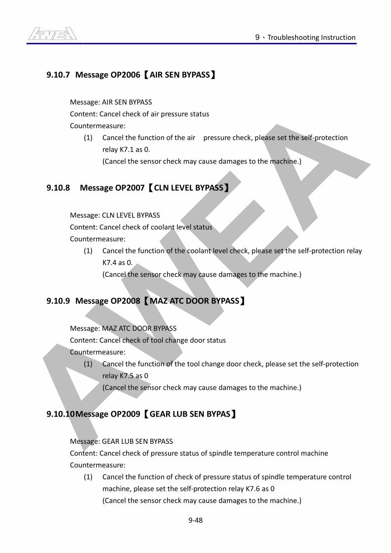
AWEA 9、Troubleshooting Instruction
9-48
9.10.7 Message OP2006【AIR SEN BYPASS】
Message: AIR SEN BYPASS
Content: Cancel check of air pressure status
Countermeasure:
(1) Cancel the function of the air pressure check, please set the self-protection
relay K7.1 as 0.
(Cancel the sensor check may cause damages to the machine.)
9.10.8 Message OP2007【CLN LEVEL BYPASS】
Message: CLN LEVEL BYPASS
Content: Cancel check of coolant level status
Countermeasure:
(1) Cancel the function of the coolant level check, please set the self-protection relay
K7.4 as 0.
(Cancel the sensor check may cause damages to the machine.)
9.10.9 Message OP2008【MAZ ATC DOOR BYPASS】
Message: MAZ ATC DOOR BYPASS
Content: Cancel check of tool change door status
Countermeasure:
(1) Cancel the function of the tool change door check, please set the self-protection
relay K7.5 as 0
(Cancel the sensor check may cause damages to the machine.)
9.10.10 Message OP2009【GEAR LUB SEN BYPAS】
Message: GEAR LUB SEN BYPASS
Content: Cancel check of pressure status of spindle temperature control machine
Countermeasure:
(1) Cancel the function of check of pressure status of spindle temperature control
machine, please set the self-protection relay K7.6 as 0
(Cancel the sensor check may cause damages to the machine.)
AWEA 9、Troubleshooting Instruction
9-49
9.10.11 Message OP2010【LUB. LEVEL BYPASS】
Message: UB. LEVEL BYPASS
Content: Cancel check of LUBE level status
Countermeasure:
(1) Cancel the function of the LUBE level status check, please set the self-protection
relay K7.7 as 0
(Cancel the sensor check may cause damages to the machine.)
9.10.12 Message OP2011【SAFE DOOR BYPASS】
Message: SAFE DOOR BYPASS
Content: Cancel check of tool change door status
Countermeasure:
(1) Press the 【RESET】 button and 【CYCLE STOP】 button to clear the access door
check canceling mode.
(Cancel the sensor check may cause damages to the machine.)
【THIS MESSAGE IS VALID WHEN THE CE FUNCTION IS OPEN.】
9.10.13 Message OP2013【TOOL GROUP LIFE END】
Message: TOOL GROUP LIFE END
Content: Tool life ended
Countermeasure:
(1) Replace the service-life-ending tools and clear the old information in the
service-life manager.
【REFER TO THE CHAPTER OF TOOL SERVICE-LIFE FUNCTION TO SEE THE
SERVICE-LIFE OPERATION DESCRIPTION.】
AWEA 9、Troubleshooting Instruction
9-50
9.10.14 Message OP2014【OPERATION OF MAZ MAN DOOR IS INVALID】
Message: OPERATION OF MAZ MAN DOOR IS INVALID
Content: MAZ door open operation is invalid
Countermeasure:
(1) Condition error occurred when executing magazine door opening, general
opening mode is switching to manual mode with the magazine under stopping
status, then can the magazine door opening command being performed.
【THIS MESSAGE IS VALID WHEN THE CE FUNCTION IS OPEN.】
9.10.15 Message OP2015【LOW CLN LEVEL】
Message: LOW CLN LEVEL
Content: Coolant low level
Countermeasure:
(1) Coolant, low tank level is not below the low water level, to complement the
Coolant.
(2) The liquid level sensor is damaged, replace the liquid level sensor.
(3) Circuit connection error, check and repair the circuit.
9.10.16 Message OP2020【HANDLE INTERRUPT MODE ERROR】
Message: HANDLE INTERRUPT MODE ERROR
Content: Handle interrupt mode operation error
Countermeasure:
(1) Modify the operation mode to auto operation mode.
(2) Shut the manual pulse generator plug-in function.
9.10.17 Message OP2021【CHIP OP ERROR, CHECK BED CHIP OP】
Message: CHIP OP ERROR, CHECK BED CHIP OP
Content: Chip conveyor operation error
Countermeasure:
(1) Chip conveyor operation panel 【PERMISSION KEY SWITCH】 rotated to the "OFF"
position.
AWEA 9、Troubleshooting Instruction
9-51
9.10.18 Message OP2022【ATC TOOL CHECK ERROR】
Message: ATC TOOL CHECK ERROR
Content: Tool check error
Countermeasure:
(1) Unload the tool on the tool package of the magazine that corresponds to the
spindle tool no..
9.10.19 Message OP2023【HEAD CLAMP LS BYPASS】
Message: HEAD CLAMP LS BYPASS
Content: Cancel check of HEAD clamp status
Countermeasure:
(1) Cancel the function of the coolant level check, please set the self-protection relay
K7.4 as 0
(Cancel the sensor check may cause damages to the machine.)
9.10.20 Message OP2024【OP ERROR, CHECK BED OP PANEL ENABLE KEY】
Message: OP ERROR, CHECK BED OP PANEL ENABLE KEY
Content: Operator panel operation error
Countermeasure:
(1) BED side operation panel 【PERMISSION KEY SWITCH】 rotated to the "OFF"
position.
9.10.21 Message OP2026【SPINDLE OVERLOAD】
Message: SPINDLE OVERLOAD
Content: Spindle load value set
Countermeasure:
(1) Adjust the detection time of the spindle load. TMR/36 time setting.
(2) Implementation of 【CYCLE START】button to continue the program processing.
【WHEN SPINDLE LOAD MONITORING FUNCTION IS ACTIVATED, THIS MESSAGE
IS VALID.】
AWEA 9、Troubleshooting Instruction
9-52
9.10.22 Message OP2028【SPINDLE OVER SPEED】
Message: SPINDLE OVER SPEED
Content: Spindle speed is over
Countermeasure:
(1) Clear alarm, and restart S command.
9.10.23 Message OP2030【MAZ DOOR OPEN】
Message: MAZ DOOR OPEN
Content: MAZ door is in open state.
Countermeasure:
(1) When the MAZ door is open, the message prompt will occur. Restore method:
close the MAZ door.
9.10.24 Message OP2031【MAZ DOOR CLOSE STATE】
Message: MAZ DOOR CLOSE STATE
Content: MAZ door is in close state.
Countermeasure:
(1) This message will occur when executing the manual tool mounting motion in the
MAZ with the MAZ door being shut. Open the MAZ door to restore the condition.
9.10.25 Message OP2032【MAZ OPERATION】
Message: MAZ OPERATION
Content: Tool magazine in under manual operation
Countermeasure:
(1) This message will occur to inform the operator when the manual tool magazine
operation is sufficient. Switch the 【THE PERMISSION KEY SWITCH OF THE TOOL
MAGAZINE PANEL】 to position “0” to restore the condition.
AWEA 9、Troubleshooting Instruction
9-53
9.10.26 Message OP2035【LOW MIST CUT OIL LEVE】
Message: LOW MIST CUT OIL LEVEL
Content: Oil mist coolant level is over-low
Countermeasure:
(1) Oil mist coolant level is over-low, please add the mist of Coolant.
(2) Mist cutting low-level sensor failure, maintenance related circuit or replace the
liquid level sensor.
9.10.27 Message OP2036【CTS FILTER PRESSURE IS INVALID】
Message: CTS FILTER PRESSURE IS INVALID
Content: Coolant through spindle filter is in stuck state.
Countermeasure:
(1) The high pressure filter can is blocked while using the central outlet. Please take
off the high pressure filter can to clean up after the power is shutting down.
(2) The high-pressure filter tank pressure sensor is damaged, repair-related circuit or
replace the pressure sensor.
【THIS MESSAGE IS VALID WHEN THE CE FUNCTION IS OPEN.】
9.10.28 Message OP2037【FILTER PRESSURE IS INVALID】
Message: FILTER PRESSURE IS INVALID
Content: High tank filter stuck
Countermeasure:
(1) The low tank pumping to high water tank to use the filter tank to plug, plug the
power is turned off, remove the canister cleaning.
(2) High-water tank filter tank pressure sensor is damaged, the repair-related circuit
or replace the pressure sensor.
【THIS MESSAGE IS VALID WHEN THE CE FUNCTION IS OPEN.】
AWEA 9、Troubleshooting Instruction
9-54
9.10.29 Message OP2038【LOW AIR PRESSURE】
Message: LOW AIR PRESSURE
Content: Air pressure lower
Countermeasure:
(1) When shortage of pressure source occurred, adjust the air pressure. The normal
air pressure required is 5~7kg/cm^2.
(2) Hose broke and leaked, replace damaged pressure pipe.
(3) If hose connection loosed, please fix the loosing pneumatic connector.
(4) Adjust the pressure switch setting when the pressure switch setting has a poor
design. The correct setting pressure switch is 4kg/cm^2.
(5) Pressure switch failed, replace the switch or leading wire.
9.10.30 Message OP2060【MAZ ARM ROTATION OP ERROR】
Message: MAZ ARM ROTATION OP ERROR
Content: ARM rotation operation error
Countermeasure:
(1) Verify that the tool magazine arm is located in the median or spindle side
position.
(2) Check if the tool-changing arm is at the under position.
(3) Check the hydraulic pressure to see if it is under normal condition.
(4) Rule out the alarm of the tool magazine.
(5) Cancel the machine locked.
(6) Shut the door of the tool magazine.
9.10.31 Message OP2061【MAZ ROTATION OP ERROR】
Message: MAZ ROTATION OP ERROR
Content: Tool magazine rotation operation error
Countermeasure:
(1) Verify that the tool magazine arm is located in the median or spindle side
position.
(2) Check the hydraulic pressure to see if it is under normal condition.
AWEA 9、Troubleshooting Instruction
9-55
(3) Check the manual/auto tool magazine to see if the tool cylinder is under
grabbing-status.
(4) Rule out the alarm of the tool magazine.
(5) Cancel the machine locked.
(6) Shut the door of the tool magazine.
9.10.32 Message OP2062【MAZ ARM UP/DWN OP ERROR】
Message: MAZ ARM UP/DWN OP ERROR
Content: ARM UP/DWN operation error
Countermeasure:
(1) Verify that the tool magazine arm is located in the median or spindle side
position.
(2) Confirm the tool change arm rotation with or without positioning.
(3) Verify that the knife chain stopped state.
(4) Rule out the alarm of the tool magazine.
(5) Check the air pressure to see if it is under normal condition.
(6) Cancel the machine locked.
(7) Shut the door of the tool magazine.
9.10.33 Message OP2063【MAZ ARM H-MOVE OP ERROR】
Message: MAZ ARM H-MOVE OP ERROR
Content: ARM move operation error
Countermeasure:
(1) Confirm the tool change arm rotation with or without positioning.
(2) Confirm whether the up/down tool change arm is positioned or not.
(3) Check the hydraulic pressure, air pressure to see if it is under normal condition.
(4) Cancel the machine locked.
(5) Rule out the alarm of the tool magazine.
(6) Shut the door of the tool magazine.
AWEA 9、Troubleshooting Instruction
9-56
9.10.34 Message OP2069【CALL TOOL ERROR】
Message: CALL TOOL ERROR
Content: Tool call operation error
Countermeasure:
(1) This message will occur when the calling tool no. is greater than the total amount
in the tool magazine. Modify the calling tool no. to restore the condition.
9.10.35 Message OP2070【ATC MAINTENANCT MODE USE】
Message: ATC MAINTENANCE MODE USE
Content: Tool change maintenance mode is using
Countermeasure:
(1) Cancel the function of the ATC maintenance mode, please set the self-protection
relay K36.0 as 0
( When ATC maintenance mode is using, can not perform any tool
change command )
9.10.36 Message OP2080【LOW B AXIS LUB LEVEL】
Message: LOW B AXIS LUB LEVEL
Content: B-Axis oil support LUBE low level
Countermeasure:
(1) The B-Axis oil support lubricant level is over-low, please replenish the lubricant.
(2) The B-Axis oil support lubricant low level sensor failed, replace the low level
sensor.
(3) Circuit connection error, check and repair the circuit.
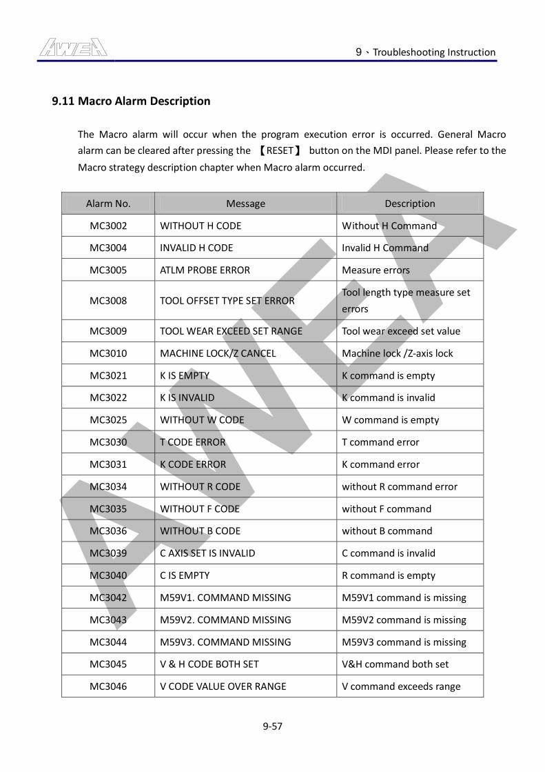
AWEA 9、Troubleshooting Instruction
9-57
9.11 Macro Alarm Description
The Macro alarm will occur when the program execution error is occurred. General Macro
alarm can be cleared after pressing the 【RESET】 button on the MDI panel. Please refer to the
Macro strategy description chapter when Macro alarm occurred.
Alarm No. Message Description
MC3002 WITHOUT H CODE Without H Command
MC3004 INVALID H CODE Invalid H Command
MC3005 ATLM PROBE ERROR Measure errors
MC3008 TOOL OFFSET TYPE SET ERROR Tool length type measure set
errors
MC3009 TOOL WEAR EXCEED SET RANGE Tool wear exceed set value
MC3010 MACHINE LOCK/Z CANCEL Machine lock /Z-axis lock
MC3021 K IS EMPTY K command is empty
MC3022 K IS INVALID K command is invalid
MC3025 WITHOUT W CODE W command is empty
MC3030 T CODE ERROR T command error
MC3031 K CODE ERROR K command error
MC3034 WITHOUT R CODE without R command error
MC3035 WITHOUT F CODE without F command
MC3036 WITHOUT B CODE without B command
MC3039 C AXIS SET IS INVALID C command is invalid
MC3040 C IS EMPTY R command is empty
MC3042 M59V1. COMMAND MISSING M59V1 command is missing
MC3043 M59V2. COMMAND MISSING M59V2 command is missing
MC3044 M59V3. COMMAND MISSING M59V3 command is missing
MC3045 V & H CODE BOTH SET V&H command both set
MC3046 V CODE VALUE OVER RANGE V command exceeds range
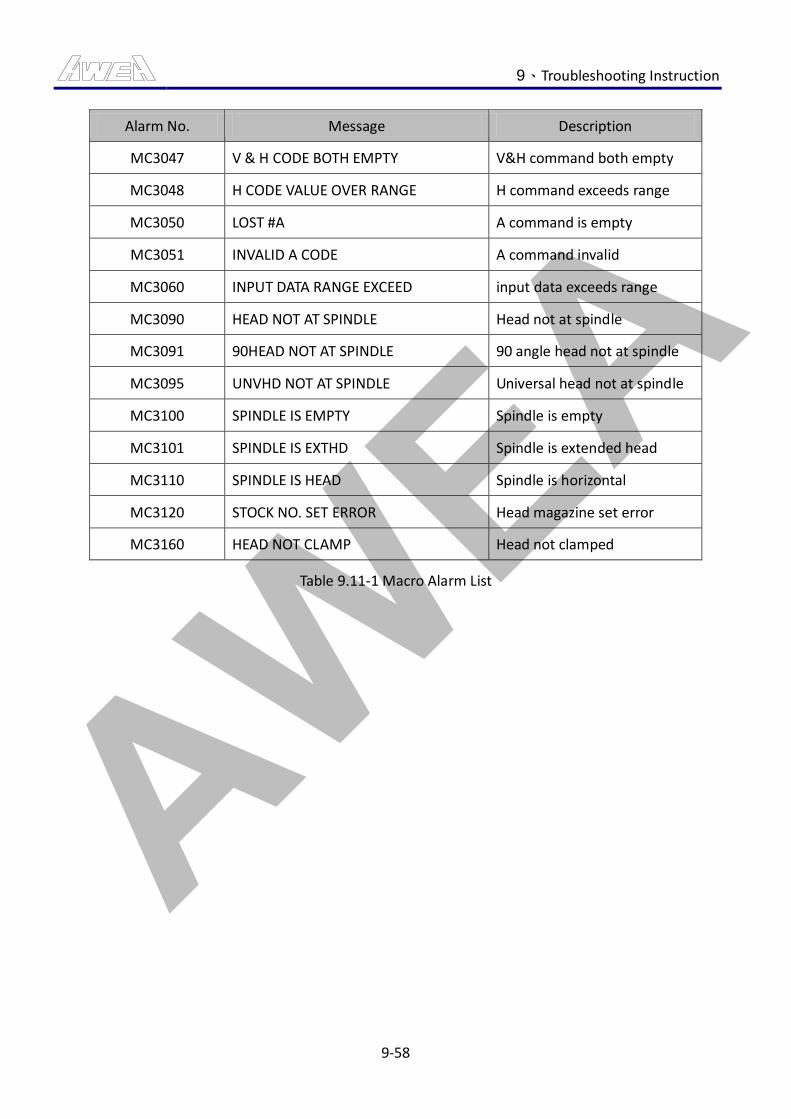
AWEA 9、Troubleshooting Instruction
9-58
Alarm No. Message Description
MC3047 V & H CODE BOTH EMPTY V&H command both empty
MC3048 H CODE VALUE OVER RANGE H command exceeds range
MC3050 LOST #A A command is empty
MC3051 INVALID A CODE A command invalid
MC3060 INPUT DATA RANGE EXCEED input data exceeds range
MC3090 HEAD NOT AT SPINDLE Head not at spindle
MC3091 90HEAD NOT AT SPINDLE 90 angle head not at spindle
MC3095 UNVHD NOT AT SPINDLE Universal head not at spindle
MC3100 SPINDLE IS EMPTY Spindle is empty
MC3101 SPINDLE IS EXTHD Spindle is extended head
MC3110 SPINDLE IS HEAD Spindle is horizontal
MC3120 STOCK NO. SET ERROR Head magazine set error
MC3160 HEAD NOT CLAMP Head not clamped
Table 9.11-1 Macro Alarm List
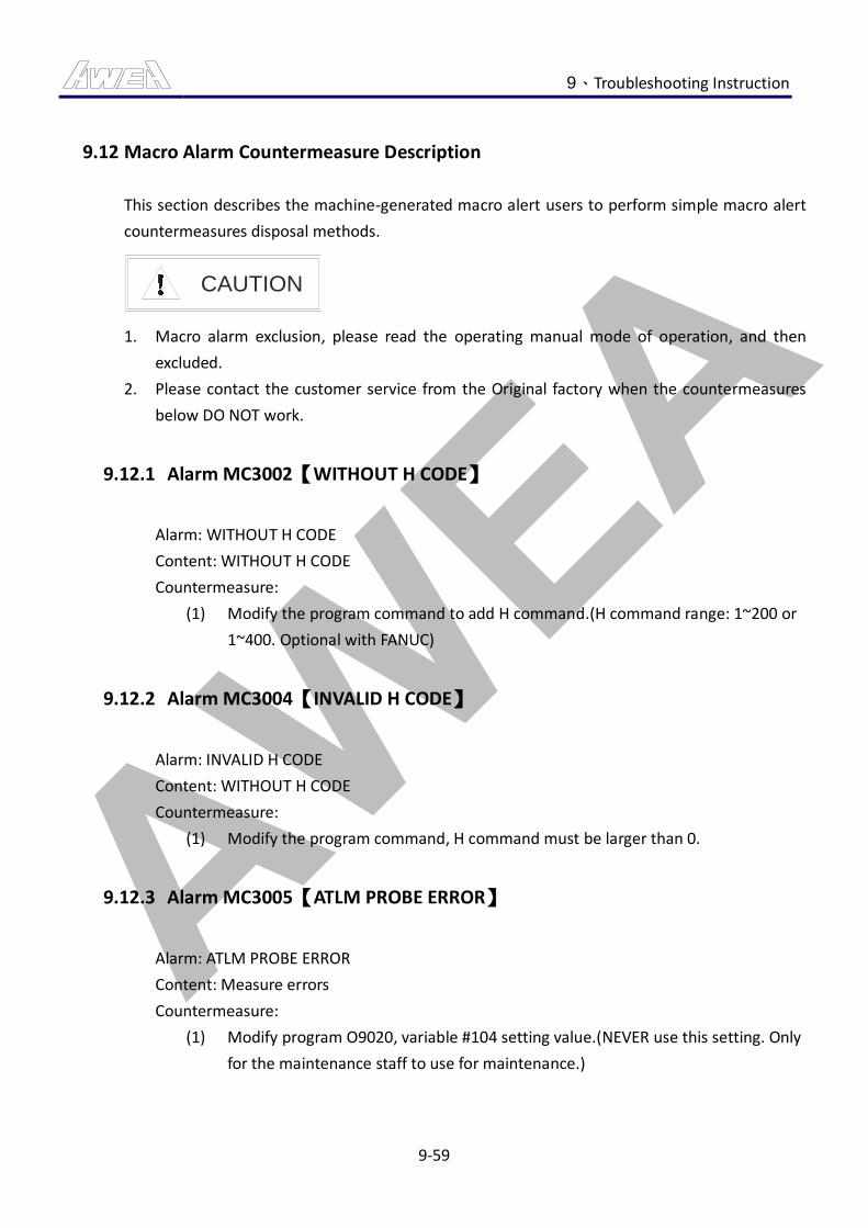
AWEA 9、Troubleshooting Instruction
9-59
9.12 Macro Alarm Countermeasure Description
This section describes the machine-generated macro alert users to perform simple macro alert
countermeasures disposal methods.
CAUTION
1. Macro alarm exclusion, please read the operating manual mode of operation, and then
excluded.
2. Please contact the customer service from the Original factory when the countermeasures
below DO NOT work.
9.12.1 Alarm MC3002【WITHOUT H CODE】
Alarm: WITHOUT H CODE
Content: WITHOUT H CODE
Countermeasure:
(1) Modify the program command to add H command.(H command range: 1~200 or
1~400. Optional with FANUC)
9.12.2 Alarm MC3004【INVALID H CODE】
Alarm: INVALID H CODE
Content: WITHOUT H CODE
Countermeasure:
(1) Modify the program command, H command must be larger than 0.
9.12.3 Alarm MC3005【ATLM PROBE ERROR】
Alarm: ATLM PROBE ERROR
Content: Measure errors
Countermeasure:
(1) Modify program O9020, variable #104 setting value.(NEVER use this setting. Only
for the maintenance staff to use for maintenance.)
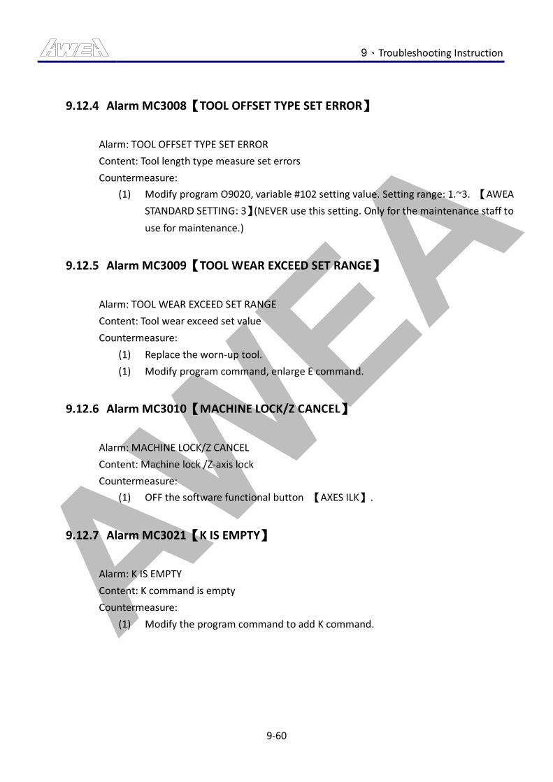
AWEA 9、Troubleshooting Instruction
9-60
9.12.4 Alarm MC3008【TOOL OFFSET TYPE SET ERROR】
Alarm: TOOL OFFSET TYPE SET ERROR
Content: Tool length type measure set errors
Countermeasure:
(1) Modify program O9020, variable #102 setting value. Setting range: 1.~3. 【AWEA
STANDARD SETTING: 3】(NEVER use this setting. Only for the maintenance staff to
use for maintenance.)
9.12.5 Alarm MC3009【TOOL WEAR EXCEED SET RANGE】
Alarm: TOOL WEAR EXCEED SET RANGE
Content: Tool wear exceed set value
Countermeasure:
(1) Replace the worn-up tool.
(1) Modify program command, enlarge E command.
9.12.6 Alarm MC3010【MACHINE LOCK/Z CANCEL】
Alarm: MACHINE LOCK/Z CANCEL
Content: Machine lock /Z-axis lock
Countermeasure:
(1) OFF the software functional button 【AXES ILK】.
9.12.7 Alarm MC3021【K IS EMPTY】
Alarm: K IS EMPTY
Content: K command is empty
Countermeasure:
(1) Modify the program command to add K command.
AWEA 9、Troubleshooting Instruction
9-61
9.12.8 Alarm MC3022【K IS INVALID】
Alarm: K IS INVALID
Content: K command is invalid
Countermeasure:
(1) Modify program O9025, is variable #119 setting correct.(NEVER use this setting.
Only for the maintenance staff to use for maintenance.)
(2) Modify the program command, K command must not be larger than #119 setting
value.
9.12.9 Alarm MC3025【WITHOUT W CODE】
Alarm: WITHOUT W CODE
Content: W command is empty
Countermeasure:
(1) Modify the program command to add W command.
9.12.10 Alarm MC3030【T CODE ERROR】
Alarm: T CODE ERROR
Content: T command error
Countermeasure:
(1) Modify the program command to add T command.
(2) Modify the program command, T command must not be
9.12.11 Alarm MC3031【K CODE ERROR】
Alarm: K CODE ERROR
Content: K command error
Countermeasure:
(1) Modify the program command, K command error. Command range: 1, 2.
AWEA 9、Troubleshooting Instruction
9-62
9.12.12 Alarm MC3034【WITHOUT R CODE】
Alarm: WITHOUT R CODE
Content: without R command error
Countermeasure:
(1) Modify the program command to add R command.
9.12.13 Alarm MC3035【WITHOUT F CODE】
Alarm: WITHOUT F CODE
Content: without F command
Countermeasure:
(1) Modify the program command to add F command.
9.12.14 Alarm MC3036【WITHOUT B CODE】
Alarm: WITHOUT B CODE
Content: without B command
Countermeasure:
(1) Modify the program command to add B command.
9.12.15 Alarm MC3039【C AXIS SET IS INVALID】
Alarm: C AXIS SET IS INVALID
Content: C command is invalid
Countermeasure:
(1) Modify program O9026, variable #110 setting value. Set range: 4, 5.【AWEA
STANDARD SETTING: 4】(NEVER use this setting. Only for the maintenance staff to
use for maintenance.)
AWEA 9、Troubleshooting Instruction
9-63
9.12.16 Alarm MC3040【C IS EMPTY】
Alarm: C IS EMPTY
Content: R command is empty
Countermeasure:
(1) Modify the program command to add C command.
9.12.17 Alarm MC3042【M59V1. COMMAND MISSING】
Alarm: M59V1. COMMAND MISSING
Content: M59V1 command is missing
Countermeasure:
(1) Modify the program command to add V1 command.
9.12.18 Alarm MC3043【M59V2. COMMAND MISSING】
Alarm: M59V2. COMMAND MISSING
Content: M59V2 command is missing
Countermeasure:
(1) Modify the program command to add V2 command.
9.12.19 Alarm MC3044【M59V3. COMMAND MISSING】
Alarm: M59V3. COMMAND MISSING
Content: M59V3 command is missing
Countermeasure:
(1) Modify the program command to add V3 command.
9.12.20 Alarm MC3045【V&H CODE BOTH SET】
Alarm: V&H CODE BOTH SET
Content: V&H command both set
Countermeasure:
(1) Modify the program command, V command and V command must not be
performed simultaneously.
AWEA 9、Troubleshooting Instruction
9-64
9.12.21 Alarm MC3046【V CODE VALUE OVER RANGE】
Alarm: V CODE VALUE OVER RANGE
Content: V command exceeds range
Countermeasure:
(1) Modify the program command, V command error. Command range: 1, 3.
9.12.22 Alarm MC3047【V&H CODE BOTH EMPTY】
Alarm: V&H CODE BOTH EMPTY
Content: V&H command both empty
Countermeasure:
(1) Modify the program command to add V command or H command.
9.12.23 Alarm MC3048【H CODE VALUE OVER RANGE】
Alarm: H CODE VALUE OVER RANGE
Content: H command exceeds range
Countermeasure:
(1) Modify the program command, H command error. Command range: 1, 3.
9.12.24 Alarm MC3050【LOST #A】
Alarm: LOST #A
Content: A command is empty
Countermeasure:
(1) Modify the program command to add A command.
9.12.25 Alarm MC3051【INVALID A CODE】
Alarm: INVALID A CODE
Content: A command invalid
Countermeasure:
(1) Modify the program command, A command error. Command range: 0~95.
AWEA 9、Troubleshooting Instruction
9-65
9.12.26 Alarm MC3060【INPUT DATA RANGE EXCEED】
Alarm: INPUT DATA RANGE EXCEED
Content: input data exceeds range
Countermeasure:
(1) Modify the program command, W command error. Command range: 0~115.
9.12.27 Alarm MC3090【HEAD NOT AT SPINDLE】
Alarm: HEAD NOT AT SPINDLE
Content: Head not at spindle
Countermeasure:
(1) Perform the M73 Kk program command to change the spindle status into HEAD
status.
9.12.28 Alarm MC3091【90HEAD NOT AT SPINDLE】
Alarm: 90HEAD NOT AT SPINDLE
Content: 90 angle head not at spindle
Countermeasure:
(1) Perform the M73 Kk program command to change the spindle status into 90
angle HEAD status.
9.12.29 Alarm MC3095【UNVHD NOT AT SPINDLE】
Alarm: UNVHD NOT AT SPINDLE
Content: Universal head not at spindle
Countermeasure:
(1) Perform the M73 Kk program command to change the spindle status into
Universal HEAD status.
AWEA 9、Troubleshooting Instruction
9-66
9.12.30 Alarm MC3100【SPINDLE IS EMPTY】
Alarm: SPINDLE IS EMPTY
Content: Spindle is empty
Countermeasure:
(1) Perform the M73 Kk program command to change the spindle status into Cap or
HEAD status.
9.12.31 Alarm MC3101【SPINDLE IS EXTHD】
Alarm: SPINDLE IS EXTHD
Content: Spindle is extended head
Countermeasure:
(1) Perform the M73 Kk program command to change the spindle status into
non-extended head status.
9.12.32 Alarm MC3110【SPINDLE IS HEAD】
Alarm: SPINDLE IS HEAD
Content: Spindle is horizontal
Countermeasure:
(1) Perform the M73 Kk program command to change the spindle status into vertical
status.
9.12.33 Alarm: MC3120【STOCK NO. SET ERROR】
Alarm: STOCK NO. SET ERROR
Content: Head magazine set error
Countermeasure:
Modify program O9025, variable setting value. Set range: 1, 2.(NEVER use this setting.
Only for the maintenance staff to use for maintenance.)
AWEA 9、Troubleshooting Instruction
9-67
9.12.34 Alarm: MC3160【HEAD NOT CLAMP】
Alarm: HEAD NOT CLAMP
Content: Head not clamped
Countermeasure:
(1) Perform M111 under I/O BY PASS mode.
(2) Change the mode into manual mode and press the 【A-HEAD UNCLAMP】 button
till the button light is off.