Embed Size (px)
Citation preview
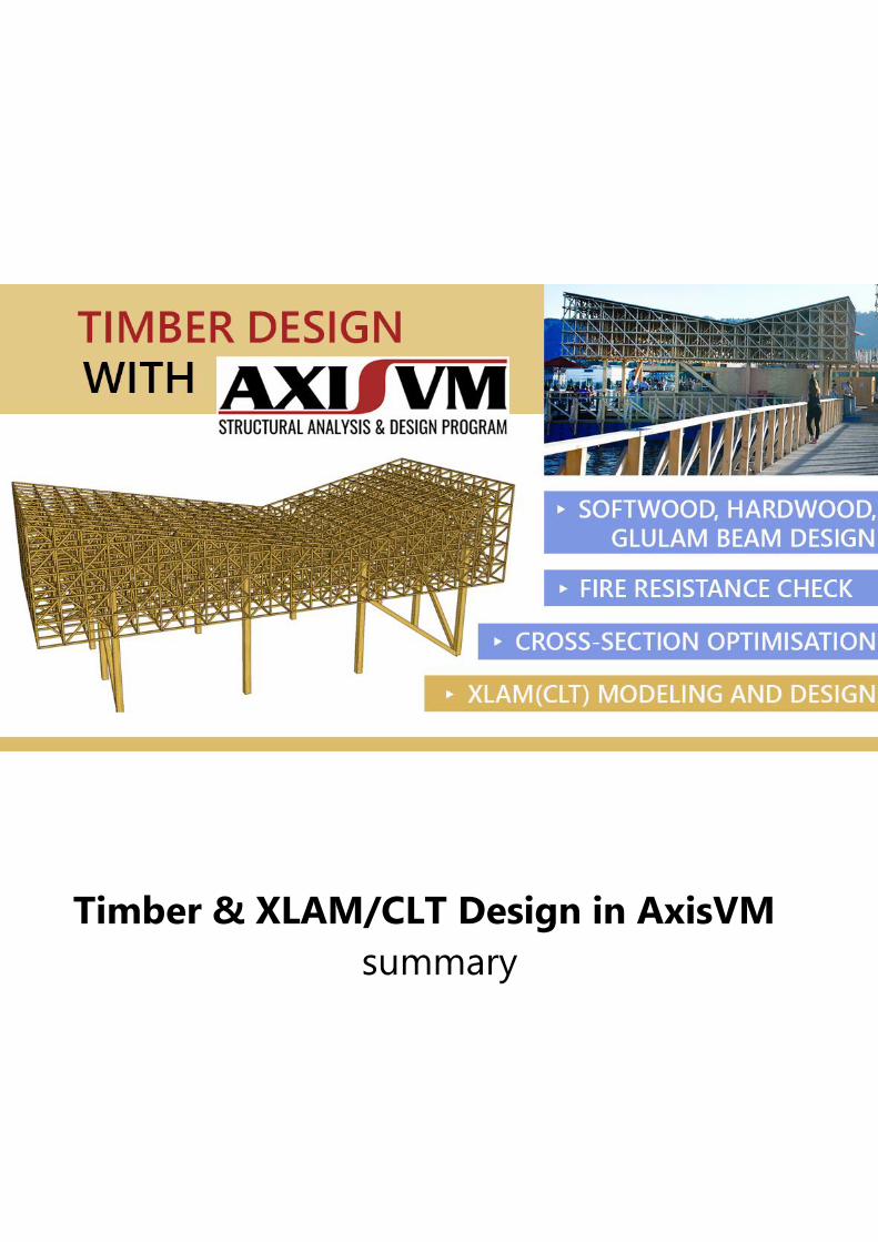
Timber & XLAM/CLT Design in AxisVM
summary
2
1. Timber design for beam structures
1.1. Timber beam design – TD1 module
EUROCODE 5
(EN 1995-1-
1:2004)
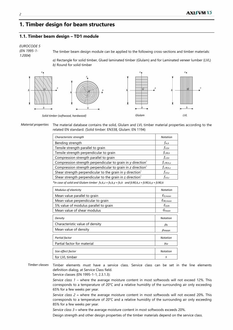
The timber beam design module can be applied to the following cross-sections and timber materials:
a) Rectangle for solid timber, Glued laminated timber (Glulam) and for Laminated veneer lumber (LVL)
b) Round for solid timber
Solid timber (softwood, hardwood)
Glulam LVL
Material properties The material database contains the solid, Glulam and LVL timber material properties according to the
related EN standard. (Solid timber: EN338, Glulam: EN 1194)
Characteristic strength Notation
Bending strength fm,k
Tensile strength parallel to grain ft,0,k
Tensile strength perpendicular to grain ft,90,k
Compression strength parallel to grain fc,0,k
Compression strength perpendicular to grain in y direction* fc,90,k,y
Compression strength perpendicular to grain in z direction* fc,90,k,z
Shear strength perpendicular to the grain in y direction* fv,k,y
Shear strength perpendicular to the grain in z direction* fv,k,z
*In case of solid and Glulam timber fv,k,z = fv,k,y = fv,k and fc90,k,z = fc90,k,y = fc90,k
Modulus of elasticity Notation
Mean value parallel to grain E0,mean
Mean value perpendicular to grain E90,mean
5% value of modulus parallel to grain E0,05
Mean value of shear modulus Gmean
Density Notation
Characteristic value of density ρk
Mean value of density ρmean
Partial factor Notation
Partial factor for material γM
Size effect factor Notation
for LVL timber s
Timber classes Timber elements must have a service class. Service class can be set in the line elements
definition dialog, at Service Class field.
Service classes (EN 1995-1-1, 2.3.1.3):
Service class 1 – where the average moisture content in most softwoods will not exceed 12%. This
corresponds to a temperature of 20°C and a relative humidity of the surrounding air only exceeding
65% for a few weeks per year.
Service class 2 – where the average moisture content in most softwoods will not exceed 20%. This
corresponds to a temperature of 20°C and a relative humidity of the surrounding air only exceeding
85% for a few weeks per year.
Service class 3 – where the average moisture content in most softwoods exceeds 20%.
Design strength and other design properties of the timber materials depend on the service class.
Timber design summary 3
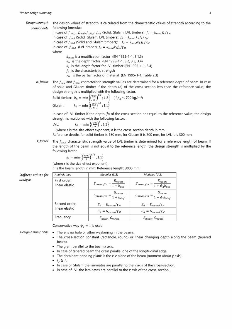
Design strength
components
The design values of strength is calculated from the characteristic values of strength according to the
following formulas:
In case of 𝑓𝑡,90,𝑑 , 𝑓𝑐,0,𝑑 , 𝑓𝑐,90,𝑑 , 𝑓𝑣,𝑑 (Solid, Glulam, LVL timbers): 𝑓𝑑 = 𝑘𝑚𝑜𝑑𝑓𝑘 𝛾𝑀⁄
In case of 𝑓𝑚,𝑑 (Solid, Glulam, LVL timbers): 𝑓𝑑 = 𝑘𝑚𝑜𝑑𝑘ℎ𝑓𝑘 𝛾𝑀⁄
In case of 𝑓𝑡,0,𝑑 (Solid and Glulam timbers): 𝑓𝑑 = 𝑘𝑚𝑜𝑑𝑘ℎ𝑓𝑘/𝛾𝑀
In case of 𝑓𝑡,0,𝑑 (LVL timber): 𝑓𝑑 = 𝑘𝑚𝑜𝑑𝑘𝑙𝑓𝑘/𝛾𝑀
where
𝑘𝑚𝑜𝑑 is a modification factor (EN 1995-1-1, 3.1.3)
𝑘ℎ is the depth factor (EN 1995-1-1, 3.2, 3.3, 3.4)
𝑘𝑙 is the length factor for LVL timber (EN 1995-1-1, 3.4)
𝑓𝑘 is the characteristic strength
𝛾𝑀 is the partial factor of material (EN 1995-1-1, Table 2.3)
kh factor The 𝑓𝑚,𝑘 and 𝑓𝑡,0,𝑘 characteristic strength values are determined for a reference depth of beam. In case
of solid and Glulam timber if the depth (h) of the cross-section less than the reference value, the
design strength is multiplied with the following factor.
Solid timber: 𝑘ℎ = min {(150
ℎ)
0.2; 1.3} (if 𝜌𝑘 ≤ 700 kg/m3)
Glulam: 𝑘ℎ = min {(600
ℎ)
0.1; 1.1}
In case of LVL timber if the depth (h) of the cross-section not equal to the reference value, the design
strength is multiplied with the following factor.
LVL: 𝑘ℎ = min {(300
ℎ)
𝑠; 1.2}
(where s is the size effect exponent, h is the cross-section depth in mm.
Reference depths for solid timber is 150 mm, for Glulam it is 600 mm, for LVL it is 300 mm.
kl factor The 𝑓𝑡,0,𝑘 characteristic strength value of LVL timber is determined for a reference length of beam. If
the length of the beam is not equal to the reference length, the design strength is multiplied by the
following factor.
𝑘𝑙 = min {(3000
𝑙)
𝑠/2; 1.1}
(where s is the size effect exponent).
𝑙 is the beam length in mm. Reference length: 3000 mm.
Stiffness values for
analysis
Analysis type Modulus (SLS) Modulus (ULS)
First order,
linear elastic 𝐸𝑚𝑒𝑎𝑛,𝑓𝑖𝑛 =
𝐸𝑚𝑒𝑎𝑛
1 + 𝑘𝑑𝑒𝑓 𝐸𝑚𝑒𝑎𝑛,𝑓𝑖𝑛 =
𝐸𝑚𝑒𝑎𝑛
1 + 𝜓2𝑘𝑑𝑒𝑓
𝐺𝑚𝑒𝑎𝑛,𝑓𝑖𝑛 =𝐺𝑚𝑒𝑎𝑛
1 + 𝑘𝑑𝑒𝑓 𝐺𝑚𝑒𝑎𝑛,𝑓𝑖𝑛 =
𝐺𝑚𝑒𝑎𝑛
1 + 𝜓2𝑘𝑑𝑒𝑓
Second order,
linear elastic 𝐸𝑑 = 𝐸𝑚𝑒𝑎𝑛/𝛾𝑀 𝐸𝑑 = 𝐸𝑚𝑒𝑎𝑛/𝛾𝑀
𝐺𝑑 = 𝐺𝑚𝑒𝑎𝑛/𝛾𝑀 𝐺𝑑 = 𝐺𝑚𝑒𝑎𝑛/𝛾𝑀
Frequency 𝐸𝑚𝑒𝑎𝑛, 𝐺𝑚𝑒𝑎𝑛 𝐸𝑚𝑒𝑎𝑛, 𝐺𝑚𝑒𝑎𝑛
Conservative way 𝜓2 = 1 is used.
Design assumptions
• There is no hole or other weakening in the beams.
• The cross-section constant (rectangle, round) or linear changing depth along the beam (tapered
beam).
• The grain parallel to the beam x axis.
• In case of tapered beam the grain parallel one of the longitudinal edge.
• The dominant bending plane is the x-z plane of the beam (moment about y axis).
• 𝐼𝑦 ≥ 𝐼𝑧
• In case of Glulam the laminates are parallel to the y axis of the cross-section.
• in case of LVL the laminates are parallel to the z axis of the cross-section.
4
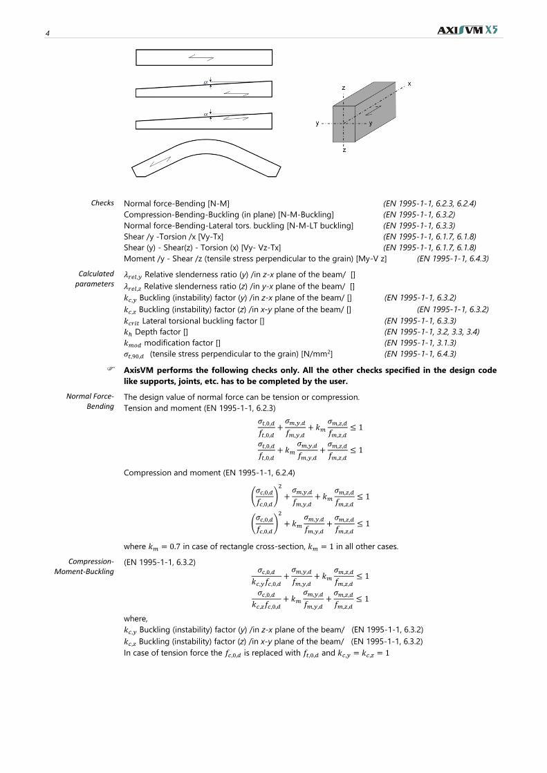
Checks
Normal force-Bending [N-M] (EN 1995-1-1, 6.2.3, 6.2.4)
Compression-Bending-Buckling (in plane) [N-M-Buckling] (EN 1995-1-1, 6.3.2)
Normal force-Bending-Lateral tors. buckling [N-M-LT buckling] (EN 1995-1-1, 6.3.3)
Shear /y -Torsion /x [Vy-Tx] (EN 1995-1-1, 6.1.7, 6.1.8)
Shear (y) - Shear(z) - Torsion (x) [Vy- Vz-Tx] (EN 1995-1-1, 6.1.7, 6.1.8)
Moment /y - Shear /z (tensile stress perpendicular to the grain) [My-V z] (EN 1995-1-1, 6.4.3)
Calculated parameters
𝜆𝑟𝑒𝑙,𝑦 Relative slenderness ratio (y) /in z-x plane of the beam/ []
𝜆𝑟𝑒𝑙,𝑧 Relative slenderness ratio (z) /in y-x plane of the beam/ []
𝑘𝑐,𝑦 Buckling (instability) factor (y) /in z-x plane of the beam/ [] (EN 1995-1-1, 6.3.2)
𝑘𝑐,𝑧 Buckling (instability) factor (z) /in x-y plane of the beam/ [] (EN 1995-1-1, 6.3.2)
𝑘𝑐𝑟𝑖𝑡 Lateral torsional buckling factor [] (EN 1995-1-1, 6.3.3)
𝑘ℎ Depth factor [] (EN 1995-1-1, 3.2, 3.3, 3.4)
𝑘𝑚𝑜𝑑 modification factor [] (EN 1995-1-1, 3.1.3)
𝜎𝑡,90,𝑑 (tensile stress perpendicular to the grain) [N/mm2] (EN 1995-1-1, 6.4.3)
AxisVM performs the following checks only. All the other checks specified in the design code
like supports, joints, etc. has to be completed by the user.
Normal Force-Bending
The design value of normal force can be tension or compression.
Tension and moment (EN 1995-1-1, 6.2.3)
𝜎𝑡,0,𝑑
𝑓𝑡,0,𝑑+
𝜎𝑚,𝑦,𝑑
𝑓𝑚,𝑦,𝑑+ 𝑘𝑚
𝜎𝑚,𝑧,𝑑
𝑓𝑚,𝑧,𝑑≤ 1
𝜎𝑡,0,𝑑
𝑓𝑡,0,𝑑+ 𝑘𝑚
𝜎𝑚,𝑦,𝑑
𝑓𝑚,𝑦,𝑑+
𝜎𝑚,𝑧,𝑑
𝑓𝑚,𝑧,𝑑≤ 1
Compression and moment (EN 1995-1-1, 6.2.4)
(𝜎𝑐,0,𝑑
𝑓𝑐,0,𝑑)
2
+𝜎𝑚,𝑦,𝑑
𝑓𝑚,𝑦,𝑑+ 𝑘𝑚
𝜎𝑚,𝑧,𝑑
𝑓𝑚,𝑧,𝑑≤ 1
(𝜎𝑐,0,𝑑
𝑓𝑐,0,𝑑)
2
+ 𝑘𝑚
𝜎𝑚,𝑦,𝑑
𝑓𝑚,𝑦,𝑑+
𝜎𝑚,𝑧,𝑑
𝑓𝑚,𝑧,𝑑≤ 1
where 𝑘𝑚 = 0.7 in case of rectangle cross-section, 𝑘𝑚 = 1 in all other cases.
Compression-Moment-Buckling
(EN 1995-1-1, 6.3.2) 𝜎𝑐,0,𝑑
𝑘𝑐,𝑦𝑓𝑐,0,𝑑+
𝜎𝑚,𝑦,𝑑
𝑓𝑚,𝑦,𝑑+ 𝑘𝑚
𝜎𝑚,𝑧,𝑑
𝑓𝑚,𝑧,𝑑≤ 1
𝜎𝑐,0,𝑑
𝑘𝑐,𝑧𝑓𝑐,0,𝑑+ 𝑘𝑚
𝜎𝑚,𝑦,𝑑
𝑓𝑚,𝑦,𝑑+
𝜎𝑚,𝑧,𝑑
𝑓𝑚,𝑧,𝑑≤ 1
where,
𝑘𝑐,𝑦 Buckling (instability) factor (y) /in z-x plane of the beam/ (EN 1995-1-1, 6.3.2)
𝑘𝑐,𝑧 Buckling (instability) factor (z) /in x-y plane of the beam/ (EN 1995-1-1, 6.3.2)
In case of tension force the 𝑓𝑐,0,𝑑 is replaced with 𝑓𝑡,0,𝑑 and 𝑘𝑐,𝑦 = 𝑘𝑐,𝑧 = 1
Timber design summary 5
Normal force-Bending-
LT buckling
For lateral torsional buckling check the program assumptions that the beam is bending in z-x plane
(about y axis). If there is simultaneous 𝑀𝑧 moment on the beam and the compression stress from 𝑀𝑧
reach the 3% of the 𝑓𝑐,0,𝑑 a warning message appears.
Bending only (EN 1995-1-1, 6.3.3) 𝜎𝑚,𝑑
𝑘𝑐𝑟𝑖𝑡𝑓𝑚,𝑑≤ 1
Compression and moment (EN 1995-1-1, 6.3.3)
(𝜎𝑚,𝑑
𝑘𝑐𝑟𝑖𝑡𝑓𝑚,𝑑)
2
+𝜎𝑐𝑑
𝑘𝑐,𝑧𝑓𝑐,0,𝑑≤ 1
Tension and bending
In case of small tension and bending that lateral torsional buckling could be occur, however there is
no rule in EC5 for this case.
The following conservative check is used.
|𝜎𝑚𝑡,𝑑|
𝑘𝑐𝑟𝑖𝑡𝑓𝑚,𝑑≤ 1;
𝜎𝑚𝑡,𝑑 =𝑀𝑑
𝑊𝑦+
𝑁𝑑
𝐴< 0
where 𝑘𝑐𝑟𝑖𝑡 is the lateral buckling factor according to the following
𝜆𝑟𝑒𝑙,𝑚 ≤ 0.75 𝑘𝑐𝑟𝑖𝑡 = 1
0.75 < 𝜆𝑟𝑒𝑙,𝑚 ≤ 1.4 𝑘𝑐𝑟𝑖𝑡 = 1.56 − 0.75 ⋅ 𝜆𝑟𝑒𝑙,𝑚
1.4 < 𝜆𝑟𝑒𝑙,𝑚 𝑘𝑐𝑟𝑖𝑡 = 1/𝜆𝑟𝑒𝑙,𝑚2
Shear-Torsion There is no rule in EC5 for case of simultaneous shear force and torsional moment.
In this case the program uses the interaction formula according to DIN EN 1995-1-1/NA:2010.
Shear(y) , Shear(z) and torsion
max [𝜏𝑣,𝑦,𝑑
𝑓𝑣,𝑑;𝜏𝑣,𝑧,𝑑
𝑓𝑣,𝑑;
𝜏𝑡𝑜𝑟,𝑑
𝑘𝑠ℎ𝑎𝑝𝑒𝑓𝑣,𝑑+ (
𝜏𝑣,𝑦,𝑑
𝑓𝑣,𝑑)
2
+ (𝜏𝑣,𝑧,𝑑
𝑓𝑣,𝑑)
2
] ≤ 1
where,
𝑘𝑠ℎ𝑎𝑝𝑒 is a factor for the shape of cross-section.
For round cross-section 𝑘𝑠ℎ𝑎𝑝𝑒 = 1.2,
for rectangular cross-section 𝑘𝑠ℎ𝑎𝑝𝑒 = min{1 + 0.15 ⋅ ℎ 𝑏⁄ ; 2.0}
Moment-Shear In case of curved beams the program checks the tensile stress perpendicular to the grain from My and
Vz forces. (EN 1995-1-1, 6.4.3.)
Moment(y)-Shear(z) 𝜏𝑑
𝑓𝑣,𝑑+
𝜎𝑡,90,𝑑
𝑘𝑑𝑖𝑠𝑘𝑣𝑜𝑙𝑓𝑡,90,𝑑≤ 1
𝑘𝑑𝑖𝑠 is a factor which takes into account the effect of the stress distribution in the apex zone (𝑘𝑑𝑖𝑠 =
1.4 for curved beams)
𝑘𝑣𝑜𝑙 is a volume factor 𝑘𝑣𝑜𝑙 = [𝑉0 𝑉⁄ ]0.2
6
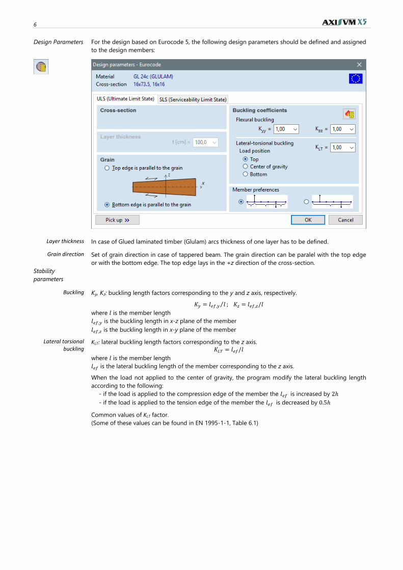
Design Parameters For the design based on Eurocode 5, the following design parameters should be defined and assigned
to the design members:
Layer thickness In case of Glued laminated timber (Glulam) arcs thickness of one layer has to be defined.
Grain direction Set of grain direction in case of tappered beam. The grain direction can be paralel with the top edge
or with the bottom edge. The top edge lays in the +z direction of the cross-section.
Stability
parameters
Buckling Ky, Kz: buckling length factors corresponding to the y and z axis, respectively.
𝐾𝑦 = 𝑙𝑒𝑓,𝑦 𝑙⁄ ; 𝐾𝑧 = 𝑙𝑒𝑓,𝑧/𝑙
where 𝑙 is the member length
𝑙𝑒𝑓,𝑦 is the buckling length in x-z plane of the member
𝑙𝑒𝑓,𝑧 is the buckling length in x-y plane of the member
Lateral torsional buckling
KLT: lateral buckling length factors corresponding to the z axis.
𝐾𝐿𝑇 = 𝑙𝑒𝑓/𝑙
where 𝑙 is the member length
𝑙𝑒𝑓 is the lateral buckling length of the member corresponding to the z axis.
When the load not applied to the center of gravity, the program modify the lateral buckling length
according to the following:
- if the load is applied to the compression edge of the member the 𝑙𝑒𝑓 is increased by 2ℎ
- if the load is applied to the tension edge of the member the 𝑙𝑒𝑓 is decreased by 0.5ℎ
Common values of KLT factor.
(Some of these values can be found in EN 1995-1-1, Table 6.1)
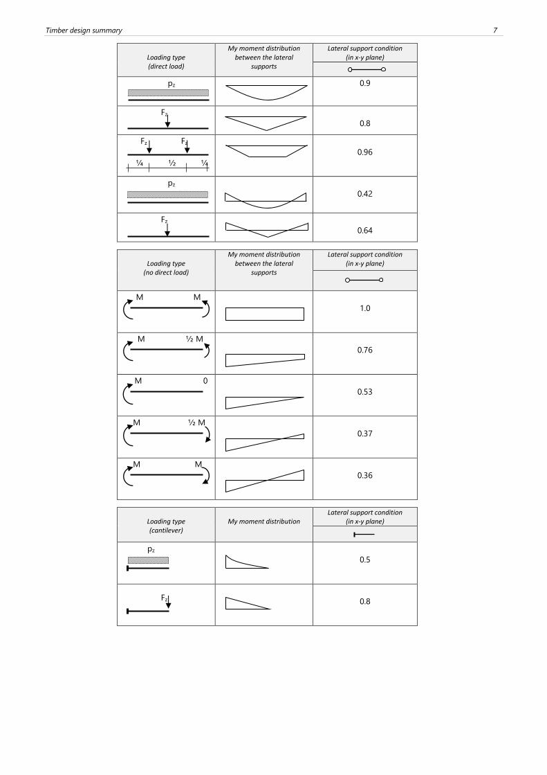
Timber design summary 7
Loading type (direct load)
My moment distribution between the lateral
supports
Lateral support condition (in x-y plane)
pz 0.9
Fz
0.8
Fz Fz
¼ ½ ¼
0.96
pz
0.42
Fz
0.64
Loading type
(no direct load)
My moment distribution between the lateral
supports
Lateral support condition (in x-y plane)
M M
1.0
M ½ M
0.76
M 0
0.53
M ½ M
0.37
M M
0.36
Loading type (cantilever)
My moment distribution
Lateral support condition (in x-y plane)
pz
0.5
Fz
0.8
8
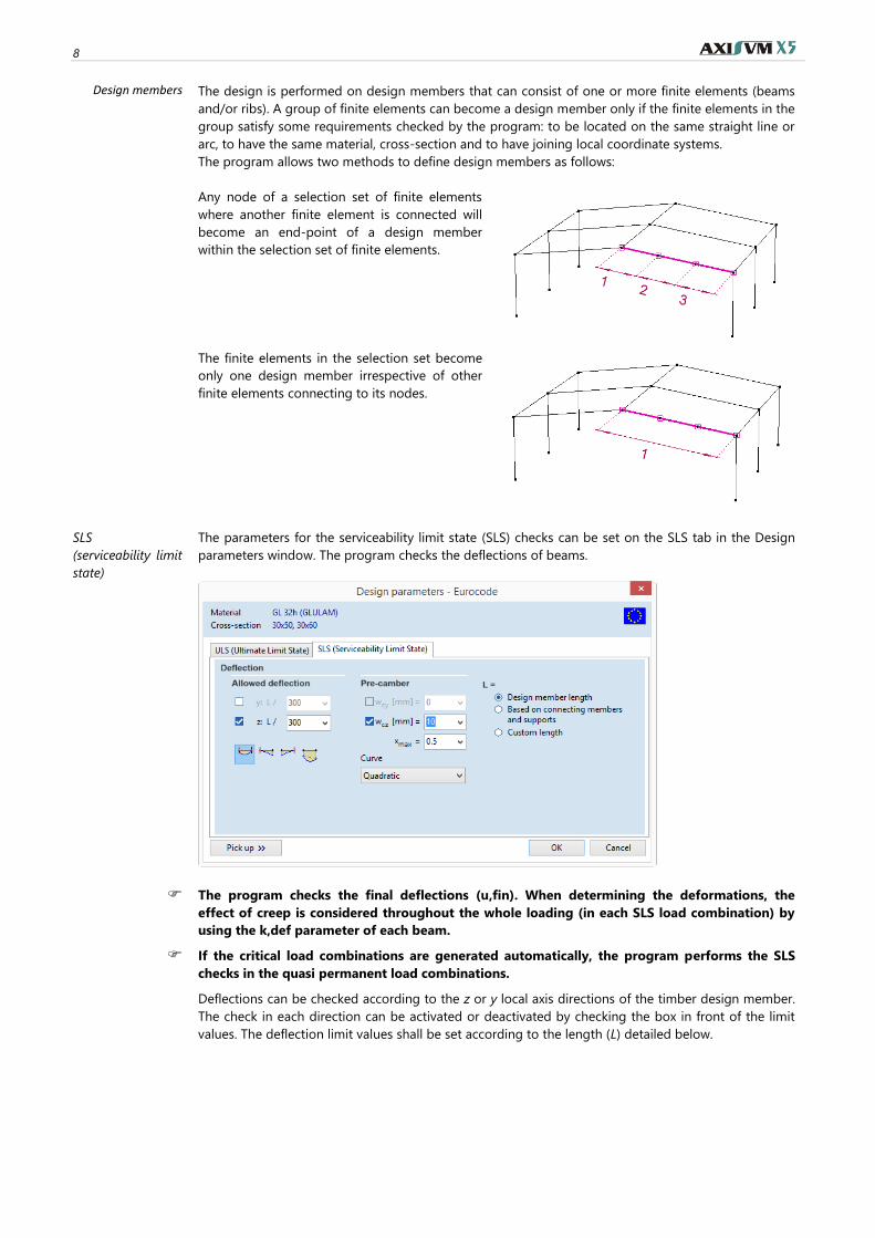
Design members The design is performed on design members that can consist of one or more finite elements (beams
and/or ribs). A group of finite elements can become a design member only if the finite elements in the
group satisfy some requirements checked by the program: to be located on the same straight line or
arc, to have the same material, cross-section and to have joining local coordinate systems.
The program allows two methods to define design members as follows:
Any node of a selection set of finite elements
where another finite element is connected will
become an end-point of a design member
within the selection set of finite elements.
The finite elements in the selection set become
only one design member irrespective of other
finite elements connecting to its nodes.
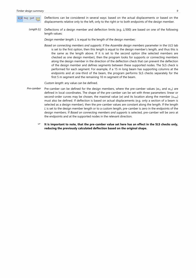
SLS
(serviceability limit
state)
The parameters for the serviceability limit state (SLS) checks can be set on the SLS tab in the Design
parameters window. The program checks the deflections of beams.
The program checks the final deflections (u,fin). When determining the deformations, the
effect of creep is considered throughout the whole loading (in each SLS load combination) by
using the k,def parameter of each beam.
If the critical load combinations are generated automatically, the program performs the SLS
checks in the quasi permanent load combinations.
Deflections can be checked according to the z or y local axis directions of the timber design member.
The check in each direction can be activated or deactivated by checking the box in front of the limit
values. The deflection limit values shall be set according to the length (L) detailed below.
Timber design summary 9
Deflections can be considered in several ways: based on the actual displacements or based on the
displacements relative only to the left, only to the right or to both endpoints of the design member.
Length (L)
Deflections of a design member and deflection limits (e.g. L/300) are based on one of the following
length values:
Design member length: L is equal to the length of the design member;
Based on connecting members and supports: if the Assemble design members parameter in the ULS tab
is set to the first option, then this length is equal to the design member’s length, and thus this is
the same as the length above. If it is set to the second option (the selected members are
checked as one design member), then the program looks for supports or connecting members
along the design member in the direction of the deflection check that can prevent the deflection
of the design member and defines segments between these supported nodes. The SLS check is
performed for each segment. For example, if a 15 m long beam has supporting columns at the
endpoints and at one-third of the beam, the program performs SLS checks separately for the
first 5 m segment and the remaining 10 m segment of the beam.
Custom length: any value can be defined.
Pre-camber
Pre-camber can be defined for the design members, where the pre-camber values (wcz and wcy) are
defined in local coordinates. The shape of the pre-camber can be set with three parameters: linear or
second-order curves may be chosen, the maximal value (w) and its location along the member (xmax)
must also be defined. If deflection is based on actual displacements (e.g. only a section of a beam is
selected as a design member), then the pre-camber values are constant along the length. If the length
L is set to the design member length or to a custom length, pre-camber is zero in the endpoints of the
design members. If Based on connecting members and supports is selected, pre-camber will be zero at
the endpoints and at the supported nodes in the relevant direction.
It is important to note, that the pre-camber value set here has an effect in the SLS checks only,
reducing the previously calculated deflection based on the original shape.
10
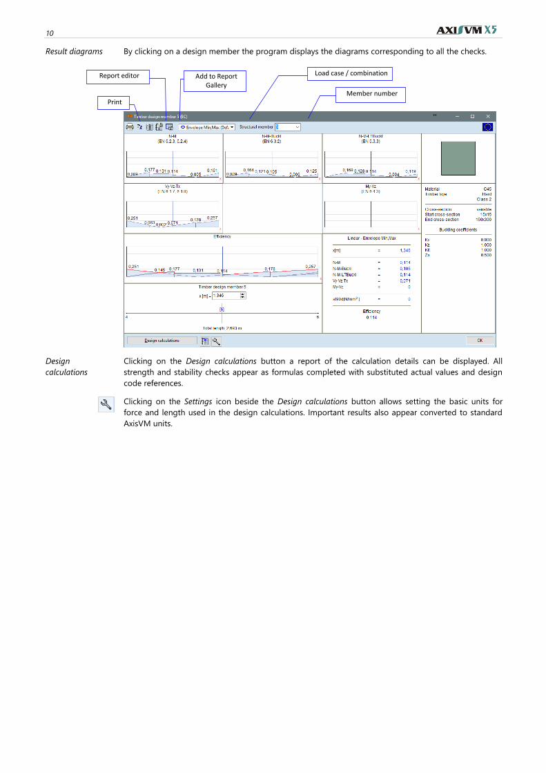
Result diagrams By clicking on a design member the program displays the diagrams corresponding to all the checks.
Design
calculations
Clicking on the Design calculations button a report of the calculation details can be displayed. All
strength and stability checks appear as formulas completed with substituted actual values and design
code references.
Clicking on the Settings icon beside the Design calculations button allows setting the basic units for
force and length used in the design calculations. Important results also appear converted to standard
AxisVM units.
Report editor Load case / combination
Member number
Add to Report Gallery
Timber design summary 11
1.2. Timber beam fire design – TD8 module
Standards AxisVM performs timber fire design according to many national codes. In case of Eurocode National
Annexes that are not listed below, general rules of EN 1993-1-2 are considered.
Eurocode
EN 1995-1-2 Eurocode 5: Design of timber structures
Part 1-2: General - Structural fire design
EC
German
DIN EN 1995-1-2:2010-12 NA
EC
Hungarian
MSZ EN 1995-1-2:2013 NA
EC
Romanian
SR EN 1995-1-2:2004/Ac:2006
EC
Czech
CSN EN 1995-1-2/NA 2011
EC
Slovakian
STN EN 1995-1-2:2008/NA:2011
EC
British
BS EN 1995-1-2:2004 NA
EC
Dutch
NEN EN 1995-1-2/NB:2016
EC
Finnish
SFS-EN 1995-1-2:2004 NA
Fire design of
timber structures according to EN
1995-1-2
Timber beam fire design (TD8 module) is based on methods of general timber beam design (see…
1.1 Timber beam design – TD1 module), thus TD1 module is a prerequisite to use TD8.
EN 1995-1-2 (EC5-1-2) discusses fire design of timber structures. This section describes the differences
between the general design and fire design.
Timber beam fire design can be performed in AxisVM if
1) the selected load combination includes a fire load case
2) if a fire effect has been assigned to any of the selected elements in that fire load case.
If different fire effects have been assigned to elements of a design member fire design cannot be
performed and an error message appears.
For selected elements without fire effect the general timber design will be performed. Timber fire
design parameters also has to be assigned to the elements (see below).
Member analysis EC5-1-2 discusses different methods: member analysis, analysis of a part of the structure and analysis of
the entire structure. Member analysis is the most widespread verification method due to its simplicity.
Analysis of a part or whole of the structure usually requires complex nonlinear numerical models and
nonlinear statical analysis.
Guiding principles of member analysis according to EC5-1-2:
• Design member internal forces can be calculated with linear static analysis;
• The boundary conditions at supports may be assumed to be constant with time. (EC5-1-2,
2.4.2 (4)).
TD8 module performs member analysis. It has to be checked whether the structure/structural part can
be verified with member analysis according to the guidelines of EC5-1-2.
12
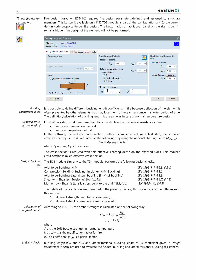
Timber fire design
parameters
Fire design based on EC5-1-2 requires fire design parameters defined and assigned to structural
members. This button is available only if 1) TD8 module is part of the configuration and 2) the current
design code supports timber fire design. The button adds an additional panel on the right side. If it
remains hidden, fire design of the element will not be performed.
Buckling coefficients in fire
It is possible to define different buckling length coefficients in fire because deflection of the element is
often prevented by other elements that may lose their stiffness or resistance in shorter period of time.
The definition/calculation of buckling length is the same as in case of normal temperature design.
Reduced cross-section method
EC5-1-2 provides two different methodology to calculate the mechanical resistance in fire:
• reduced cross-section method,
• reduced properties method.
In the software, the reduced cross-section method is implemented. As a first step, the so-called
effective charring depth is calculated on the following way using the notional charring depth (𝑑𝑐ℎ𝑎𝑟,𝑛)
𝑑𝑒𝑓 = 𝑑𝑐ℎ𝑎𝑟,𝑛 + 𝑘0𝑑0
where 𝑑0 = 7𝑚𝑚, 𝑘0 is a coefficient
The cross-section is reduced with this effective charring depth on the exposed sides. This reduced
cross-section is called effective cross-section.
Design checks in fire
The TD8 module, similarly to the TD1 module, performs the following design checks:
Axial force-Bending [N-M] (EN 1995-1-1, 6.2.3, 6.2.4)
Compression-Bending-Buckling (in plane) [N-M-Buckling] (EN 1995-1-1, 6.3.2)
Axial force-Bending-Lateral tors. buckling [N-M-LT buckling] (EN 1995-1-1, 6.3.3)
Shear (y) - Shear(z) - Torsion (x) [Vy- Vz-Tx] (EN 1995-1-1, 6.1.7, 6.1.8)
Moment /y - Shear /z (tensile stress perp. to the grain) [My-V z] (EN 1995-1-1, 6.4.3)
The details of the calculation are presented in the previous section, thus we note only the differences in
this section:
1. different strength need to be considered,
2. different stability parameters are considered.
Calculation of strength of timber
According to EC5-1-2, the timber strength is calculated on the following way:
𝑓𝑑,𝑓𝑖 = 𝑘𝑚𝑜𝑑,𝑓𝑖
𝑓20
𝛾𝑀,𝑓𝑖
𝑓20 = 𝑘𝑓𝑖𝑓𝑘
where
𝑓20 is the 20% fractile strength at normal temperature
𝑘𝑚𝑜𝑑,𝑓𝑖 = 1 is the modification factor for fire
𝑘𝑓𝑖 is a coefficient, 𝛾𝑀,𝑓𝑖 is a partial factor
Stability checks Buckling length (Ky,fi and Kz,fi) and lateral torsional buckling length (KLT,fi) coefficient given in Design
parameters window are used to evaluate the flexural buckling and lateral torsional buckling resistances.
Timber design summary 13
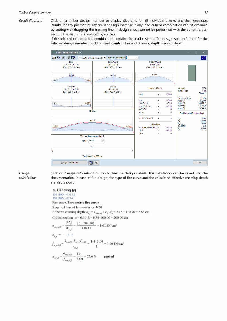
Result diagrams Click on a timber design member to display diagrams for all individual checks and their envelope.
Results for any position of any timber design member in any load case or combination can be obtained
by setting x or dragging the tracking line. If design check cannot be performed with the current cross-
section, the diagram is replaced by a cross.
If the selected or the critical combination contains fire load case and fire design was performed for the
selected design member, buckling coefficients in fire and charring depth are also shown.
Design
calculations
Click on Design calculations button to see the design details. The calculation can be saved into the
documentation. In case of fire design, the type of fire curve and the calculated effective charring depth
are also shown.
14
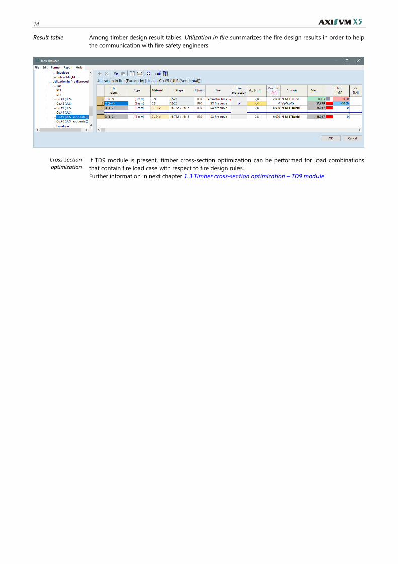
Result table Among timber design result tables, Utilization in fire summarizes the fire design results in order to help
the communication with fire safety engineers.
Cross-section optimization
If TD9 module is present, timber cross-section optimization can be performed for load combinations
that contain fire load case with respect to fire design rules.
Further information in next chapter 1.3 Timber cross-section optimization – TD9 module
Timber design summary 15
1.3. Timber cross-section optimization – TD9 module
TD9 module requires TD1 module.
Cross-section optimization of timber structures makes timber design members previously defined and
designed more efficient by fine-tuning cross-section dimensions and reducing self weight.
Optimization checks the design members for the same internal forces ignoring stiffness changes
due to changing dimensions. In certain structures recalculation of the model may show
considerable changes in internal force patterns. In these cases several consecutive optimizations
may find the more efficient structure.
Optimization uses the timber design parameters previously assigned to the design members.
Cross-section types suitable for optimization are: rectangle, rounded rectangle and circular shapes.
Variable cross-sections cannot be optimized.
For the details of the optimization see… AxisVM User’s Manual in chapter 6.6.1.4. Steel cross-section
optimization – SD9 module
16
2. XLAM domains in AxisVM
2.1. New features in XLAM module
In version AxisVM X5 the performance and capabilities of X-Lam module were improved significantly.
The main features of the module are:
• Improved ultimate limit state design, taking into account 'membrane-rolling shear' and 'shear-
torsion' interactions.
• The new utilization categories allow for the separation of effects parallel and perpendicular to
grain direction.
• New, dedicated 'XLAM' material with material constants based on statistical data fitting.
Timber design summary 17
• New display window, showing the stress distributions at a point along the thickness.
The theory and design guide includes a documented stiffness calculation based on the Mindlin-
Reissner plate theory with proper shear-correction factors in two dimensions, and the implemented
design procedure based on relevant research and ETA documents.
You can find further, detailed information in X-LAM (CLT) Theory and Design Guide.
18
2.2. Definition of XLAM domains
Handling of XLAM (CLT) panels is managed through
the definition of XLAM (CLT) domains.
This domain type requires the XLM module.
AxisVM offers a library of many common products
but custom layer structure can also be entered.
Analysis provides displacements, forces, stresses and utilizations in XLAM domains.
Definition
Browse XLAM
libraries
AxisVM has a wide variety, built-in databases from the XLAM manufacturers, which is constantly
expanding.
XLAM layer structure can be loaded from libraries
Panel Structure
Editor
This editor allows to define custom layer structure.
The Name field contains the name of the panel
structure.
Thickness is the calculated total thickness of the
panel.
The Number of layers is always odd, the layer
structure can be symmetrical or asymmetrical.
Besides the thicknesses of the individual layers, the
user can change the orientation as well.
Service Class This is a classification based on the moisture content of the material and the relative humidity. For
details see Service class in 1.1 Timber beam design – TD1 module.
Top layer grain
direction
Grain direction of the topmost layer must be specified it can be the local x or y direction.
ksys When checked, the system strength factor is taken into consideration when calculating the strength
properties of the member. For further information see the X-LAM (CLT) Theory and Design Guide.
kfin When checked, the flexural strength is taken into account with reduced value. Check it on if the
lamellas are finger-jointed. For further information see the X-LAM (CLT) Theory and Design Guide.
Timber design summary 19
Calculation Layered structures built from homogenous layers an equivalent orthotropic material stiffness matrix
can be calculated. This method converts the geometric inhomogeneity into material orthotropy
Material stiffness of a general shell element can be described with the following system of equations
{{𝑁}
{𝑀}} = [
𝒜 𝓑ℬT 𝓓
] {{𝜖0}
{𝜅}} ; {
𝑄𝑦
𝑄𝑥} = 𝐾𝑠 [
𝐴44 𝐴45
𝐴45 𝐴55] {
𝛾𝑦
𝛾𝑥}
where
𝒜 = [
𝐴11 𝐴12 𝐴16
𝐴12 𝐴22 𝐴26
𝐴16 𝐴26 𝐴66
] ; ℬ = [
𝐵11 𝐵12 𝐵16
𝐵12 𝐵22 𝐵26
𝐵16 𝐵26 𝐵66
] ; 𝒟 = [
𝐷11 𝐷12 𝐷16
𝐷12 𝐷22 𝐷26
𝐷16 𝐷26 𝐷66
]
matrices can be derived from the 6x6 stiffness matrix of the Hooke model for orthotropic materials.
ℬ represents the material relation between normal forces and bending. Ks denotes the shear correction
factor, which is uniquely determined for each lamination scheme. AxisVM handles symmetric and
asymmetric cases as well, the layer orientations must be aligned with one of the local coordinate
directions of the domain.
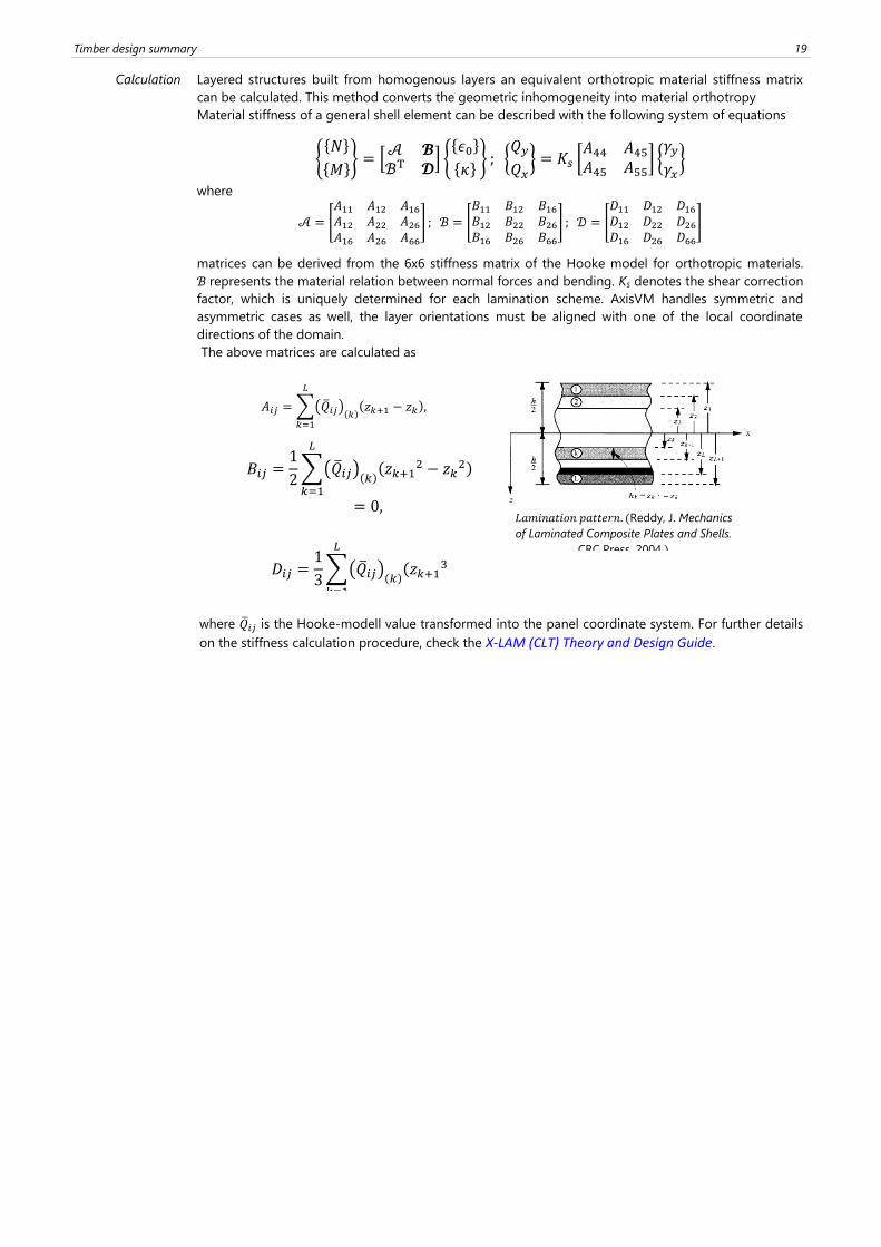
The above matrices are calculated as
where �̅�𝑖𝑗 is the Hooke-modell value transformed into the panel coordinate system. For further details
on the stiffness calculation procedure, check the X-LAM (CLT) Theory and Design Guide.
𝐴𝑖𝑗 = ൫�̅�𝑖𝑗൯ሺ𝑘ሻ
ሺ𝑧𝑘+1 − 𝑧𝑘ሻ,
𝐿
𝑘=1
𝐵𝑖𝑗 =1
2൫�̅�𝑖𝑗൯
ሺ𝑘ሻሺ𝑧𝑘+1
2 − 𝑧𝑘2ሻ
𝐿
𝑘=1
= 0,
𝐷𝑖𝑗 =1
3൫�̅�𝑖𝑗൯
ሺ𝑘ሻሺ𝑧𝑘+1
3
𝐿
𝑘=1
𝐿𝑎𝑚𝑖𝑛𝑎𝑡𝑖𝑜𝑛 𝑝𝑎𝑡𝑡𝑒𝑟𝑛. ሺReddy, J. Mechanics
of Laminated Composite Plates and Shells.
CRC Press, 2004.ሻ
20
2.3. Design of XLAM domains
Design codes There is no currently valid, overall design regulation for XLAM (CLT) panels. For further details on the
detailed calculation procedure and the references see the X-LAM (CLT) Theory and Design Guide.
Material
properties
There is a dedicated XLAM material in the material library with predefined stiffness and strength
properties. If the user wishes, the material properties can be arbitrarily modified in the material library
associated with the model.
Characteristic values of material parameters Denotement
Bending strength fm,k
Tensile strength parallel to the grain direction ft,0,k
Tensile strength perpendicular to the grain direction ft,90,k
Compressive strength parallel to the grain direction fc,0,k
Compressive strength perpendicular to the grain direction (y) fc,90,k
Compressive strength perpendicular to the grain direction (z) fc,90,k
Torsional strength fT,k
Shear strength in y direction fv,k
Shear strength in z direction fv,k
Rolling shear strength fr,k*
*assumed as 1.0 N/mm2, independently of the strength class
Stiffness values Denotement
Mean value of Young’s modulus parallel to the grain direction E0,mean
Mean value of the Young’s modulus perpendicular to the grain
direction
E90,mean
Young’s modulus parallel to the grain direction for the significance
level of 0.05
E0,05
Mean value of the shear modulus Gmean
Mean value of the rolling shear modulus GR,mean*
*it is assumed that GR,mean / Gmean = 0,1 holds, independently of the strength class
Density Denotement
Apparent density ρk
Mean value of the density ρmean
Partial safety factor Denotement
Partial safety factor of the material γM
Service classes
See in chapter 1.1 Timber beam design – TD1 module
Load duration
classes
See in chapter 1.1 Timber beam design – TD1 module
Characteristic
value of strength
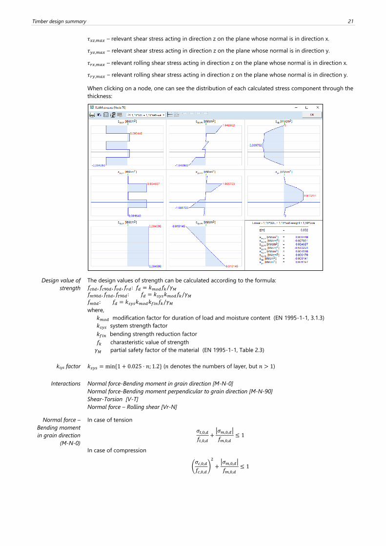
The stress values are determined independently due to bending, normal, shear and torsional actions.
𝜎𝑚𝑥,𝑡 – relevant value of the normal stress in x direction due to bending, on the upper half of the
region (the side of the region associated with the positive direction of the local z axis).
𝜎𝑚𝑥,𝑏 – relevant value of the normal stress in x direction due to bending, on the lower half of the region
(the side of the region associated with the negative direction of the local z axis).
𝜎𝑚𝑦,𝑡 – relevant value of the normal stress in y direction due to bending, on the upper half of the
region (the side of the region associated with the positive direction of the local z axis).
𝜎𝑚𝑦,𝑏 – relevant value of the normal stress in y direction due to bending, on the lower half of the region
(the side of the region associated with the negative direction of the local z axis).
𝜎𝑛𝑥 – relevant value of the normal stress in x direction due to normal forces.
𝜎𝑛𝑦 – relevant value of the normal stress in y direction due to normal forces.
𝜏𝑛,𝑥𝑦 – relevant value of in plane shear stress from normal force.
𝜏𝑚,𝑥𝑦 – relevant value of in plane shear stress from twisting moment.
Timber design summary 21
𝜏𝑥𝑧,𝑚𝑎𝑥 – relevant shear stress acting in direction z on the plane whose normal is in direction x.
𝜏𝑦𝑧,𝑚𝑎𝑥 – relevant shear stress acting in direction z on the plane whose normal is in direction y.
𝜏𝑟𝑥,𝑚𝑎𝑥 – relevant rolling shear stress acting in direction z on the plane whose normal is in direction x.
𝜏𝑟𝑦,𝑚𝑎𝑥 – relevant rolling shear stress acting in direction z on the plane whose normal is in direction y.
When clicking on a node, one can see the distribution of each calculated stress component through the
thickness:
Design value of
strength
The design values of strength can be calculated according to the formula:
𝑓𝑐0𝑑 , 𝑓𝑐90𝑑 , 𝑓𝑣𝑑 , 𝑓𝑟𝑑: 𝑓𝑑 = 𝑘𝑚𝑜𝑑𝑓𝑘 𝛾𝑀⁄
𝑓𝑚90𝑑 , 𝑓𝑡0𝑑 , 𝑓𝑡90𝑑: 𝑓𝑑 = 𝑘𝑠𝑦𝑠𝑘𝑚𝑜𝑑𝑓𝑘/𝛾𝑀
𝑓𝑚0𝑑: 𝑓𝑑 = 𝑘𝑠𝑦𝑠𝑘𝑚𝑜𝑑𝑘𝑓𝑖𝑛𝑓𝑘/𝛾𝑀
where,
𝑘𝑚𝑜𝑑 modification factor for duration of load and moisture content (EN 1995-1-1, 3.1.3)
𝑘𝑠𝑦𝑠 system strength factor
𝑘𝑓𝑖𝑛 bending strength reduction factor
𝑓𝑘 charasteristic value of strength
𝛾𝑀 partial safety factor of the material (EN 1995-1-1, Table 2.3)
ksys factor 𝑘𝑠𝑦𝑠 = min {1 + 0.025 ⋅ 𝑛; 1.2} (𝑛 denotes the numbers of layer, but 𝑛 > 1)
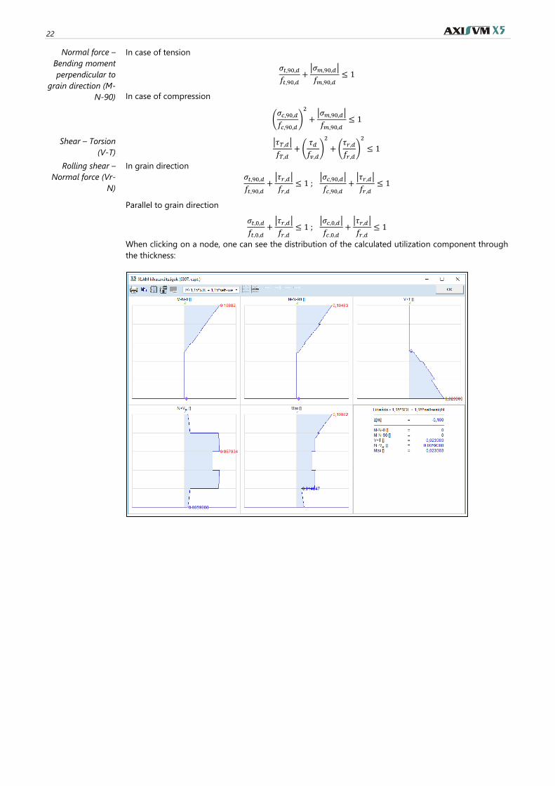
Interactions Normal force-Bending moment in grain direction [M-N-0]
Normal force-Bending moment perpendicular to grain direction [M-N-90]
Shear-Torsion [V-T]
Normal force – Rolling shear [Vr-N]
Normal force –
Bending moment
in grain direction
(M-N-0)
In case of tension
𝜎𝑡,0,𝑑
𝑓𝑡,0,𝑑+
|𝜎𝑚,0,𝑑|
𝑓𝑚,0,𝑑≤ 1
In case of compression
(𝜎𝑐,0,𝑑
𝑓𝑐,0,𝑑)
2
+|𝜎𝑚,0,𝑑|
𝑓𝑚,0,𝑑≤ 1
22
Normal force –
Bending moment
perpendicular to
grain direction (M-
N-90)
In case of tension
𝜎𝑡,90,𝑑
𝑓𝑡,90,𝑑+
|𝜎𝑚,90,𝑑|
𝑓𝑚,90,𝑑≤ 1
In case of compression
(𝜎𝑐,90,𝑑
𝑓𝑐,90,𝑑)
2
+|𝜎𝑚,90,𝑑|
𝑓𝑚,90,𝑑≤ 1
Shear – Torsion
(V-T)
|𝜏𝑇,𝑑|
𝑓𝑇,𝑑+ (
𝜏𝑑
𝑓𝑣,𝑑)
2
+ (𝜏𝑟,𝑑
𝑓𝑟,𝑑)
2
≤ 1
Rolling shear –
Normal force (Vr-
N)
In grain direction
𝜎𝑡,90,𝑑
𝑓𝑡,90,𝑑+
|𝜏𝑟,𝑑|
𝑓𝑟,𝑑≤ 1 ;
|𝜎𝑐,90,𝑑|
𝑓𝑐,90,𝑑+
|𝜏𝑟,𝑑|
𝑓𝑟,𝑑≤ 1
Parallel to grain direction
𝜎𝑡,0,𝑑
𝑓𝑡,0,𝑑+
|𝜏𝑟,𝑑|
𝑓𝑟,𝑑≤ 1 ;
|𝜎𝑐,0,𝑑|
𝑓𝑐,0,𝑑+
|𝜏𝑟,𝑑|
𝑓𝑟,𝑑≤ 1
When clicking on a node, one can see the distribution of the calculated utilization component through
the thickness: