Embed Size (px)
Citation preview
B-1 Appendix B - Reduction of Digital Logic
Principles of Computer Architecture by M. Murdocca and V. Heuring © 1999 M. Murdocca and V. Heuring
Principles of Computer ArchitectureMiles Murdocca and Vincent Heuring
Appendix B: Reduction of Digital Logic
B-2 Appendix B - Reduction of Digital Logic
Principles of Computer Architecture by M. Murdocca and V. Heuring © 1999 M. Murdocca and V. Heuring
Chapter Contents
B.1 Reduction of Combinational Logic and Sequential Logic
B.2 Reduction of Two-Level Expressions
B.3 State Reduction
B-3 Appendix B - Reduction of Digital Logic
Principles of Computer Architecture by M. Murdocca and V. Heuring © 1999 M. Murdocca and V. Heuring
Reduction (Simplification) of Boolean Expressions
• It is usually possible to simplify the canonical SOP (or POS) forms.
• A smaller Boolean equation generally translates to a lower gate count in the target circuit.
• We cover three methods: algebraic reduction, Karnaugh map reduction, and tabular (Quine-McCluskey) reduction.
B-4 Appendix B - Reduction of Digital Logic
Principles of Computer Architecture by M. Murdocca and V. Heuring © 1999 M. Murdocca and V. Heuring
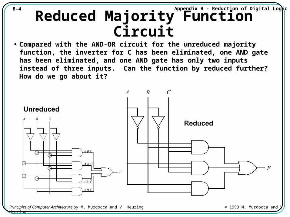
Reduced Majority Function Circuit• Compared with the AND-OR circuit for the unreduced majority function,
the inverter for C has been eliminated, one AND gate has been eliminated, and one AND gate has only two inputs instead of three inputs. Can the function by reduced further? How do we go about it?
B-5 Appendix B - Reduction of Digital Logic
Principles of Computer Architecture by M. Murdocca and V. Heuring © 1999 M. Murdocca and V. Heuring
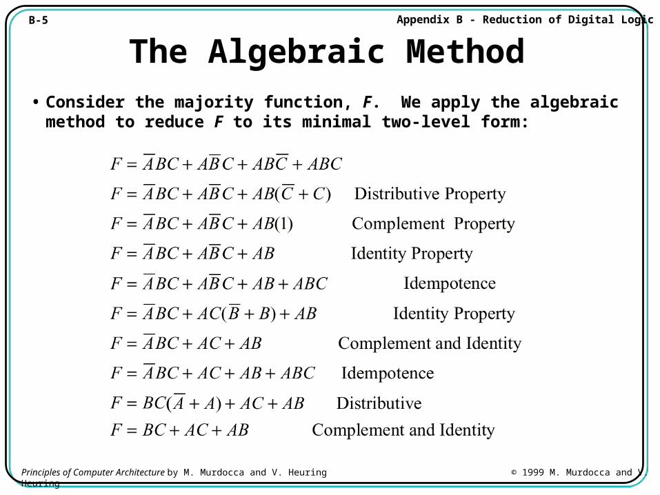
The Algebraic Method
• Consider the majority function, F. We apply the algebraic method to reduce F to its minimal two-level form:

B-6 Appendix B - Reduction of Digital Logic
Principles of Computer Architecture by M. Murdocca and V. Heuring © 1999 M. Murdocca and V. Heuring
The Algebraic Method• This majority circuit is functionally equivalent to the previous
majority circuit, but this one is in its minimal two-level form:
B-7 Appendix B - Reduction of Digital Logic
Principles of Computer Architecture by M. Murdocca and V. Heuring © 1999 M. Murdocca and V. Heuring
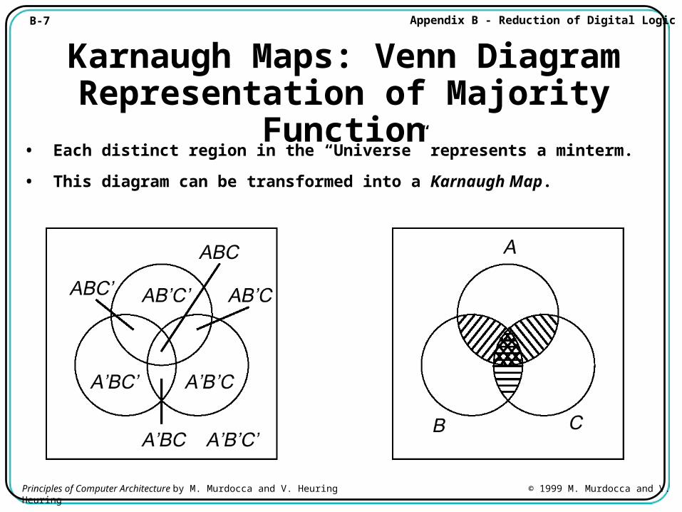
Karnaugh Maps: Venn Diagram Representation of Majority Function
• Each distinct region in the “Universe” represents a minterm.
• This diagram can be transformed into a Karnaugh Map.
B-8 Appendix B - Reduction of Digital Logic
Principles of Computer Architecture by M. Murdocca and V. Heuring © 1999 M. Murdocca and V. Heuring
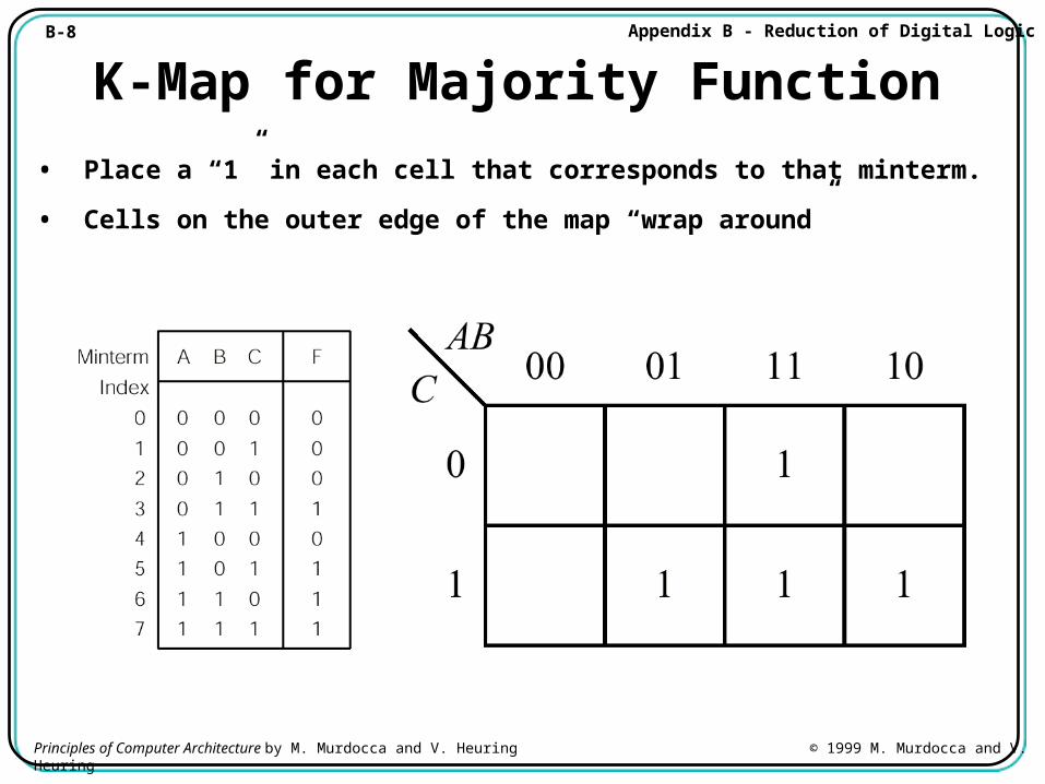
K-Map for Majority Function
• Place a “1” in each cell that corresponds to that minterm.
• Cells on the outer edge of the map “wrap around”
B-9 Appendix B - Reduction of Digital Logic
Principles of Computer Architecture by M. Murdocca and V. Heuring © 1999 M. Murdocca and V. Heuring
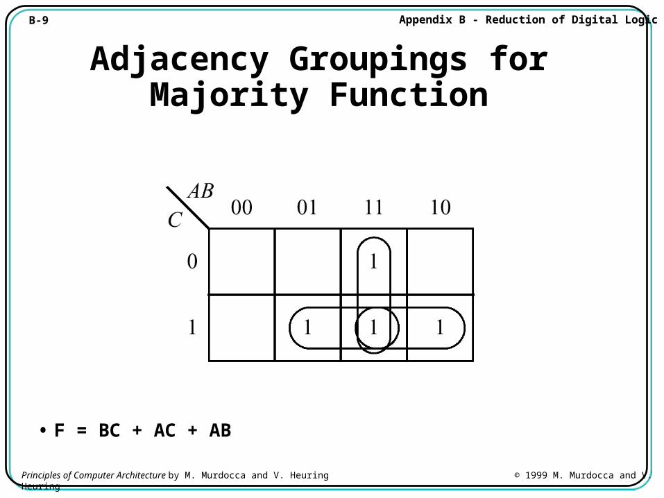
Adjacency Groupings for Majority Function
• F = BC + AC + AB
B-10 Appendix B - Reduction of Digital Logic
Principles of Computer Architecture by M. Murdocca and V. Heuring © 1999 M. Murdocca and V. Heuring
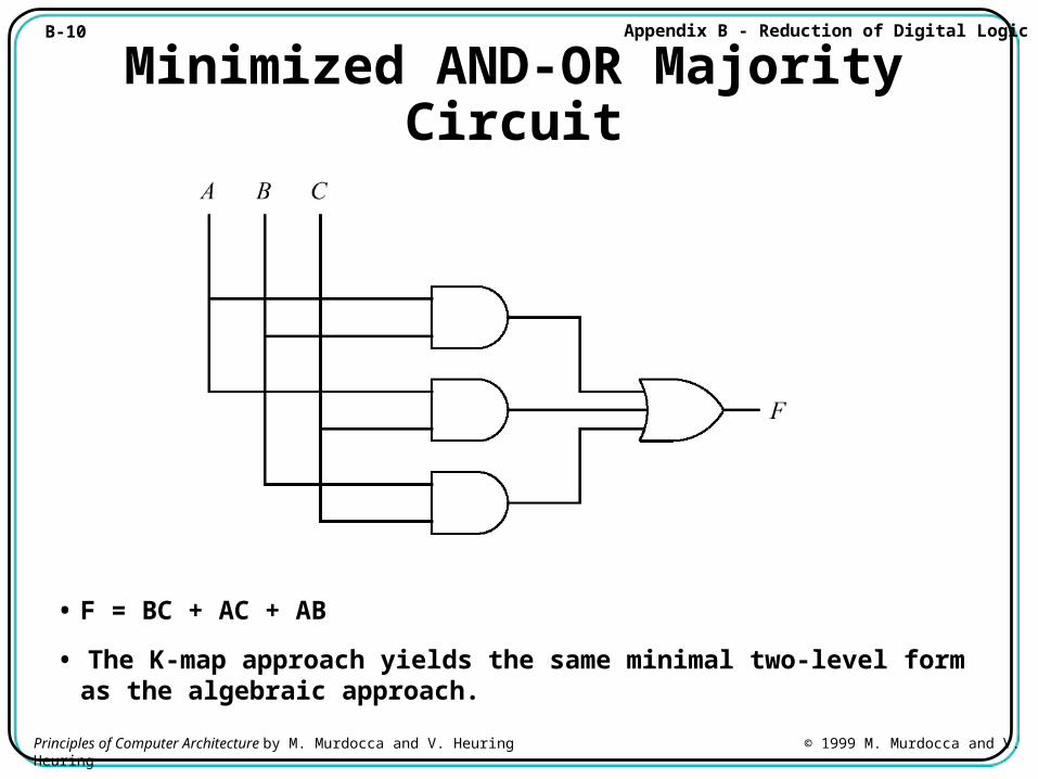
Minimized AND-OR Majority Circuit
• F = BC + AC + AB
• The K-map approach yields the same minimal two-level form as the algebraic approach.
B-11 Appendix B - Reduction of Digital Logic
Principles of Computer Architecture by M. Murdocca and V. Heuring © 1999 M. Murdocca and V. Heuring
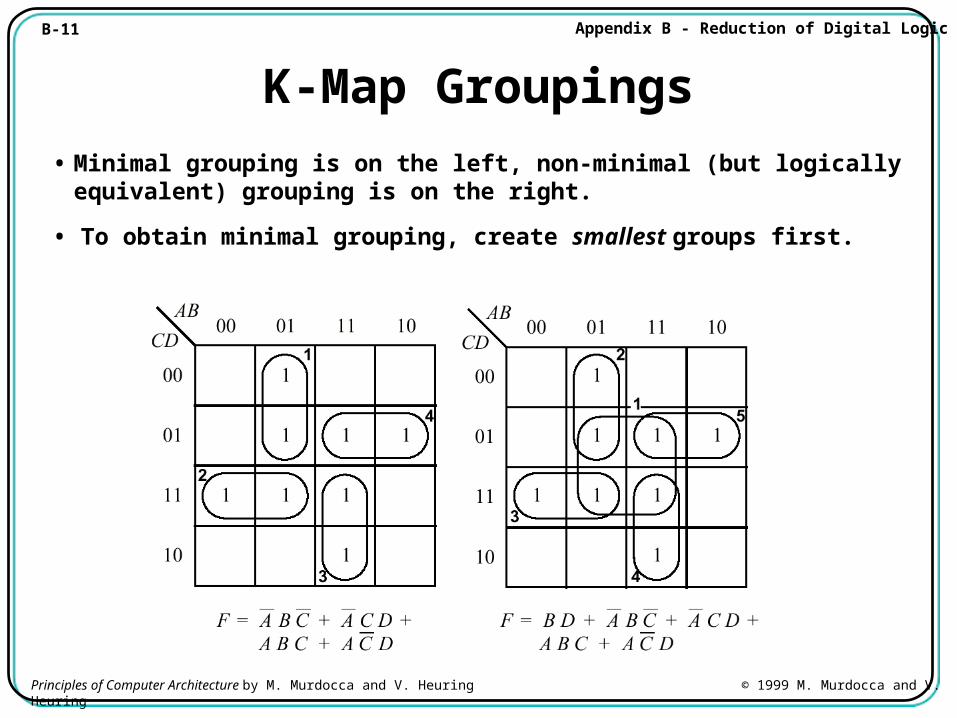
K-Map Groupings
• Minimal grouping is on the left, non-minimal (but logically equivalent) grouping is on the right.
• To obtain minimal grouping, create smallest groups first.
B-12 Appendix B - Reduction of Digital Logic
Principles of Computer Architecture by M. Murdocca and V. Heuring © 1999 M. Murdocca and V. Heuring
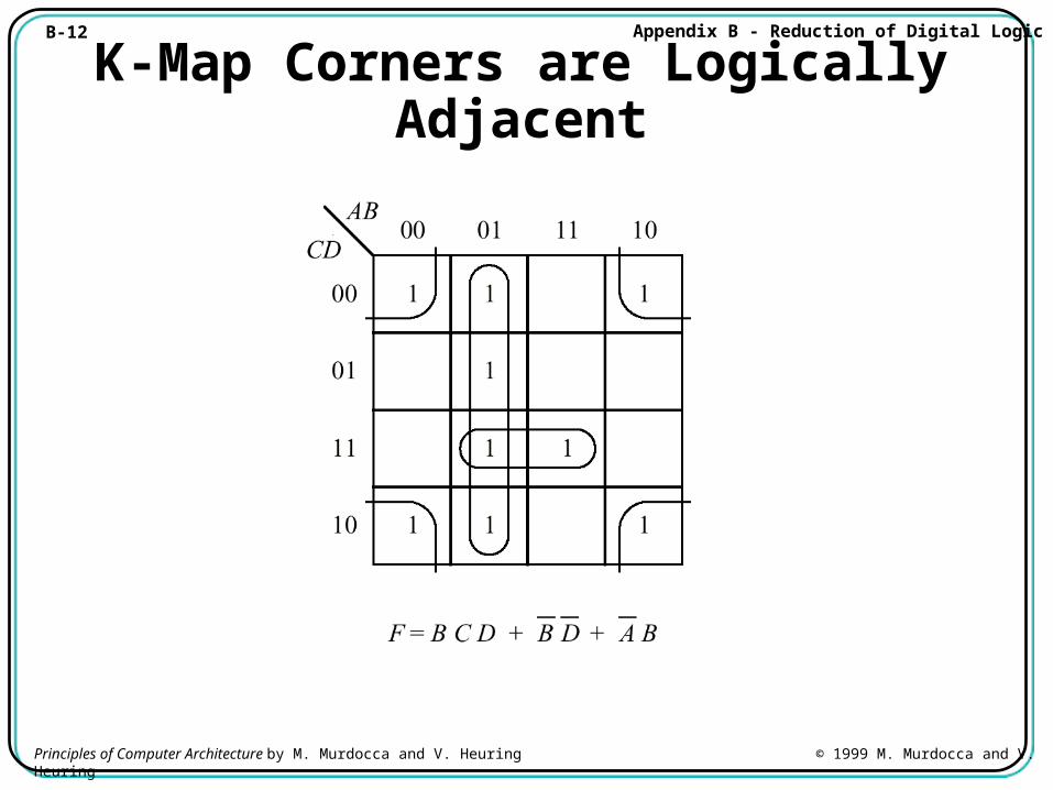
K-Map Corners are Logically Adjacent
B-13 Appendix B - Reduction of Digital Logic
Principles of Computer Architecture by M. Murdocca and V. Heuring © 1999 M. Murdocca and V. Heuring
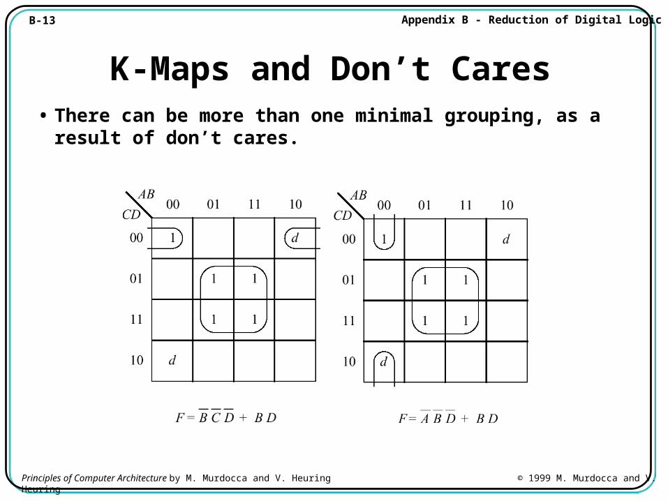
K-Maps and Don’t Cares• There can be more than one minimal grouping, as a result of don’t
cares.
B-14 Appendix B - Reduction of Digital Logic
Principles of Computer Architecture by M. Murdocca and V. Heuring © 1999 M. Murdocca and V. Heuring
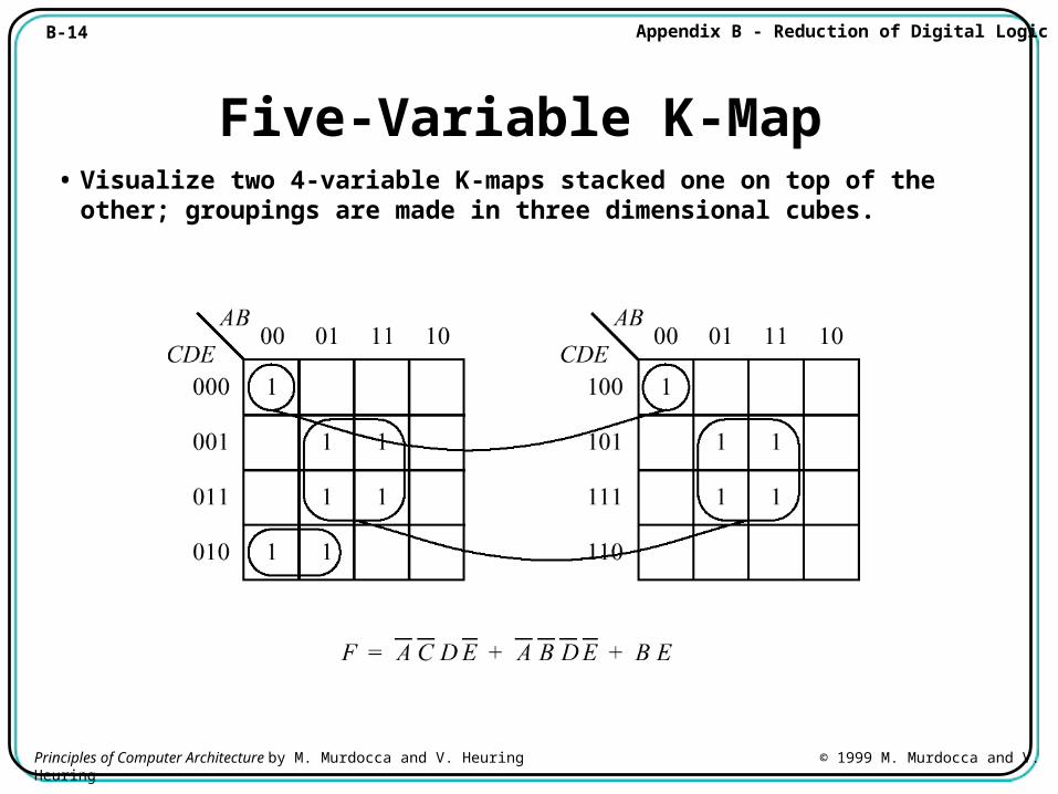
Five-Variable K-Map• Visualize two 4-variable K-maps stacked one on top of the other;
groupings are made in three dimensional cubes.
B-15 Appendix B - Reduction of Digital Logic
Principles of Computer Architecture by M. Murdocca and V. Heuring © 1999 M. Murdocca and V. Heuring
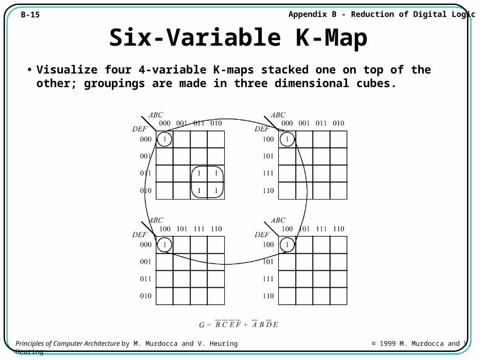
Six-Variable K-Map• Visualize four 4-variable K-maps stacked one on top of the other;
groupings are made in three dimensional cubes.
B-16 Appendix B - Reduction of Digital Logic
Principles of Computer Architecture by M. Murdocca and V. Heuring © 1999 M. Murdocca and V. Heuring
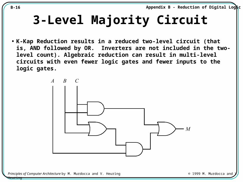
3-Level Majority Circuit
• K-Kap Reduction results in a reduced two-level circuit (that is, AND followed by OR. Inverters are not included in the two-level count). Algebraic reduction can result in multi-level circuits with even fewer logic gates and fewer inputs to the logic gates.
B-17 Appendix B - Reduction of Digital Logic
Principles of Computer Architecture by M. Murdocca and V. Heuring © 1999 M. Murdocca and V. Heuring
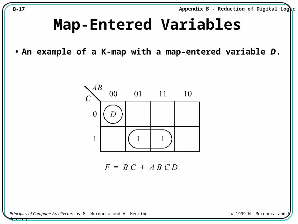
Map-Entered Variables
• An example of a K-map with a map-entered variable D.
B-18 Appendix B - Reduction of Digital Logic
Principles of Computer Architecture by M. Murdocca and V. Heuring © 1999 M. Murdocca and V. Heuring
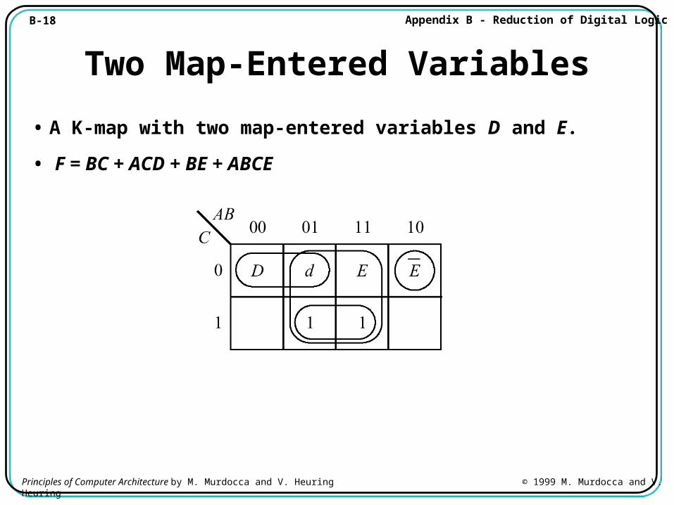
Two Map-Entered Variables
• A K-map with two map-entered variables D and E.
• F = BC + ACD + BE + ABCE
B-19 Appendix B - Reduction of Digital Logic
Principles of Computer Architecture by M. Murdocca and V. Heuring © 1999 M. Murdocca and V. Heuring
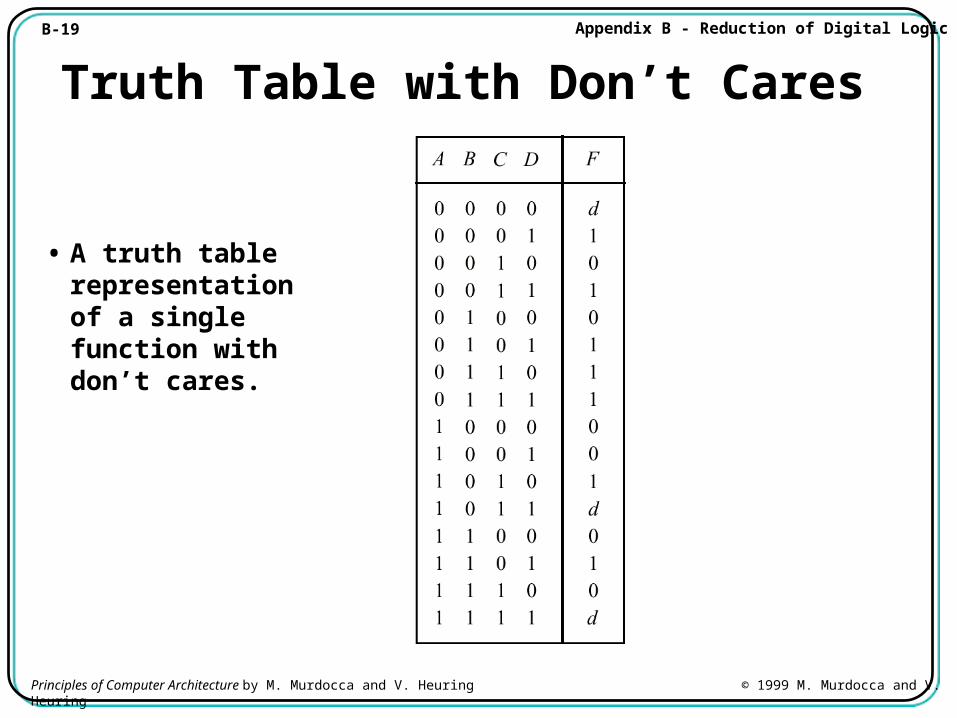
Truth Table with Don’t Cares
• A truth table representation of a single function with don’t cares.
B-20 Appendix B - Reduction of Digital Logic
Principles of Computer Architecture by M. Murdocca and V. Heuring © 1999 M. Murdocca and V. Heuring
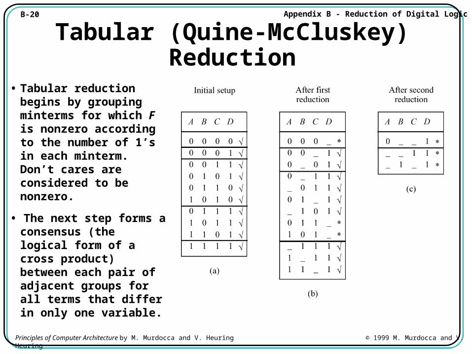
Tabular (Quine-McCluskey) Reduction
• Tabular reduction begins by grouping minterms for which F is nonzero according to the number of 1’s in each minterm. Don’t cares are considered to be nonzero.
• The next step forms a consensus (the logical form of a cross product) between each pair of adjacent groups for all terms that differ in only one variable.
B-21 Appendix B - Reduction of Digital Logic
Principles of Computer Architecture by M. Murdocca and V. Heuring © 1999 M. Murdocca and V. Heuring
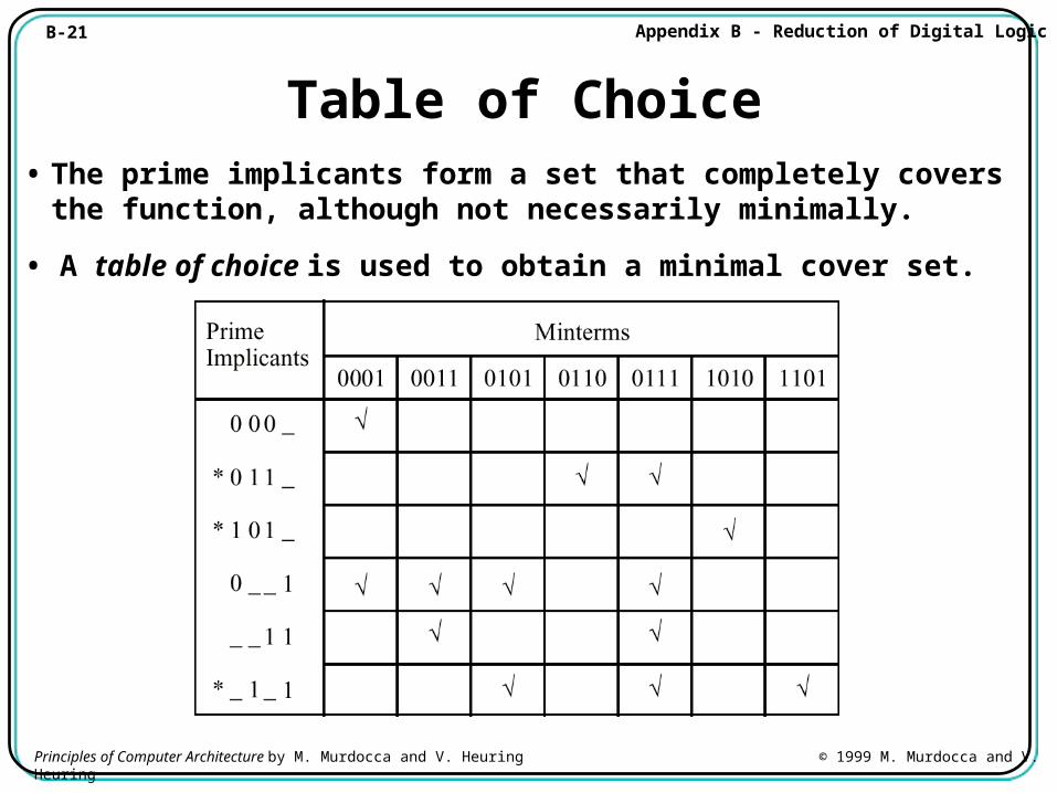
Table of Choice• The prime implicants form a set that completely covers the
function, although not necessarily minimally.
• A table of choice is used to obtain a minimal cover set.
B-22 Appendix B - Reduction of Digital Logic
Principles of Computer Architecture by M. Murdocca and V. Heuring © 1999 M. Murdocca and V. Heuring
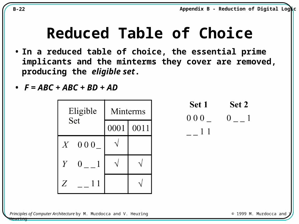
Reduced Table of Choice• In a reduced table of choice, the essential prime implicants and
the minterms they cover are removed, producing the eligible set.
• F = ABC + ABC + BD + AD
B-23 Appendix B - Reduction of Digital Logic
Principles of Computer Architecture by M. Murdocca and V. Heuring © 1999 M. Murdocca and V. Heuring
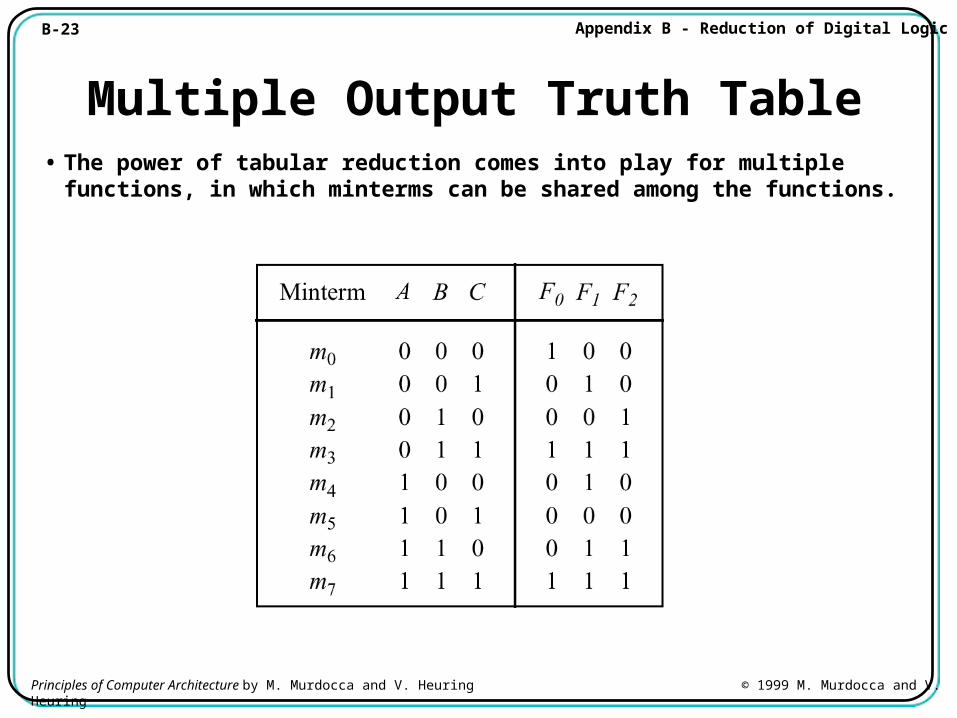
Multiple Output Truth Table• The power of tabular reduction comes into play for multiple
functions, in which minterms can be shared among the functions.
B-24 Appendix B - Reduction of Digital Logic
Principles of Computer Architecture by M. Murdocca and V. Heuring © 1999 M. Murdocca and V. Heuring
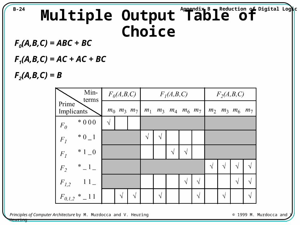
Multiple Output Table of ChoiceF0(A,B,C) = ABC + BC
F1(A,B,C) = AC + AC + BC
F2(A,B,C) = B
B-25 Appendix B - Reduction of Digital Logic
Principles of Computer Architecture by M. Murdocca and V. Heuring © 1999 M. Murdocca and V. Heuring
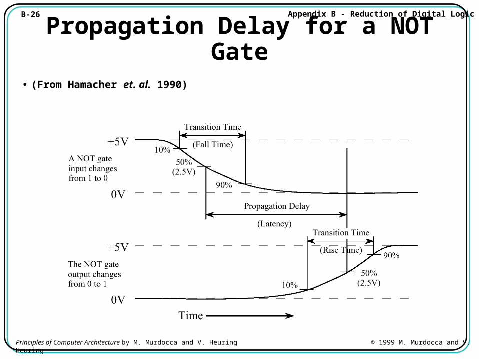
Speed and Performance
• The speed of a digital system is governed by:
• the propagation delay through the logic gates and
• the propagation delay across interconnections.
• We will look at characterizing the delay for a logic gate, and a method of reducing circuit depth using function decomposition.
B-26 Appendix B - Reduction of Digital Logic
Principles of Computer Architecture by M. Murdocca and V. Heuring © 1999 M. Murdocca and V. Heuring
Propagation Delay for a NOT Gate
• (From Hamacher et. al. 1990)
B-27 Appendix B - Reduction of Digital Logic
Principles of Computer Architecture by M. Murdocca and V. Heuring © 1999 M. Murdocca and V. Heuring
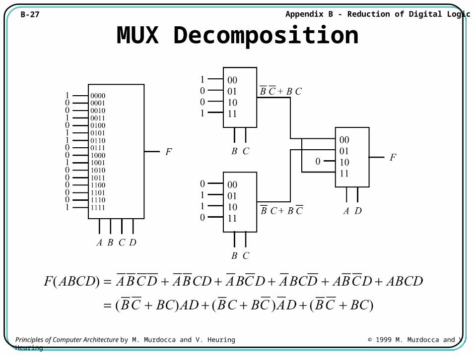
MUX Decomposition
B-28 Appendix B - Reduction of Digital Logic
Principles of Computer Architecture by M. Murdocca and V. Heuring © 1999 M. Murdocca and V. Heuring
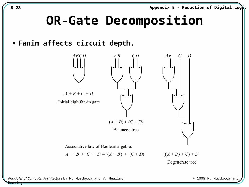
OR-Gate Decomposition
• Fanin affects circuit depth.
B-29 Appendix B - Reduction of Digital Logic
Principles of Computer Architecture by M. Murdocca and V. Heuring © 1999 M. Murdocca and V. Heuring
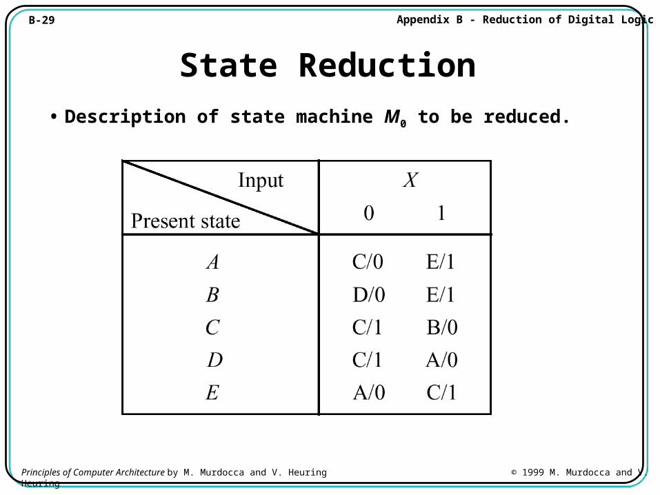
State Reduction
• Description of state machine M0 to be reduced.
B-30 Appendix B - Reduction of Digital Logic
Principles of Computer Architecture by M. Murdocca and V. Heuring © 1999 M. Murdocca and V. Heuring
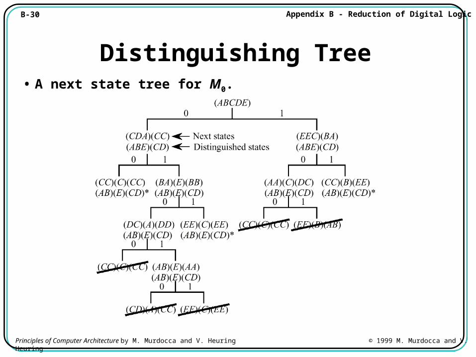
Distinguishing Tree• A next state tree for M0.
B-31 Appendix B - Reduction of Digital Logic
Principles of Computer Architecture by M. Murdocca and V. Heuring © 1999 M. Murdocca and V. Heuring
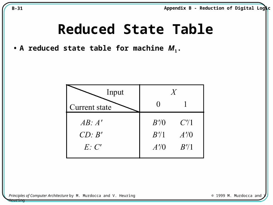
Reduced State Table• A reduced state table for machine M1.
B-32 Appendix B - Reduction of Digital Logic
Principles of Computer Architecture by M. Murdocca and V. Heuring © 1999 M. Murdocca and V. Heuring
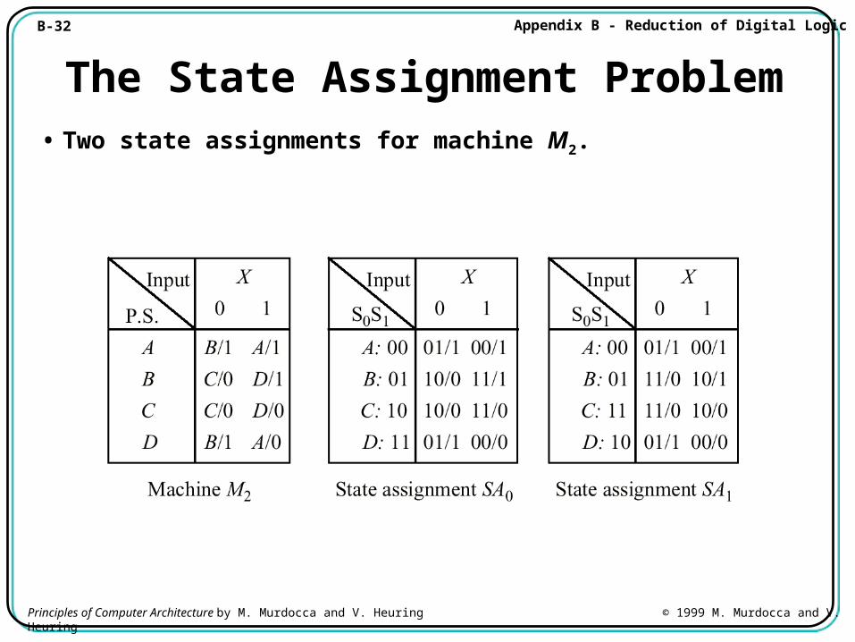
The State Assignment Problem• Two state assignments for machine M2.
B-33 Appendix B - Reduction of Digital Logic
Principles of Computer Architecture by M. Murdocca and V. Heuring © 1999 M. Murdocca and V. Heuring
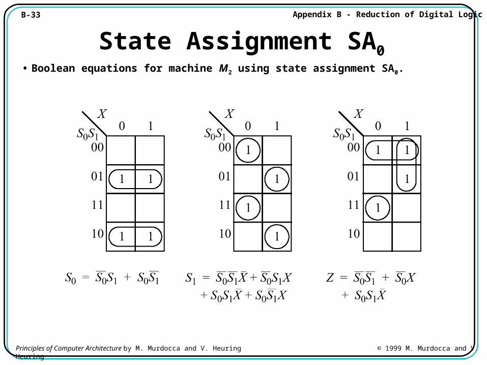
State Assignment SA0• Boolean equations for machine M2 using state assignment SA0.
B-34 Appendix B - Reduction of Digital Logic
Principles of Computer Architecture by M. Murdocca and V. Heuring © 1999 M. Murdocca and V. Heuring
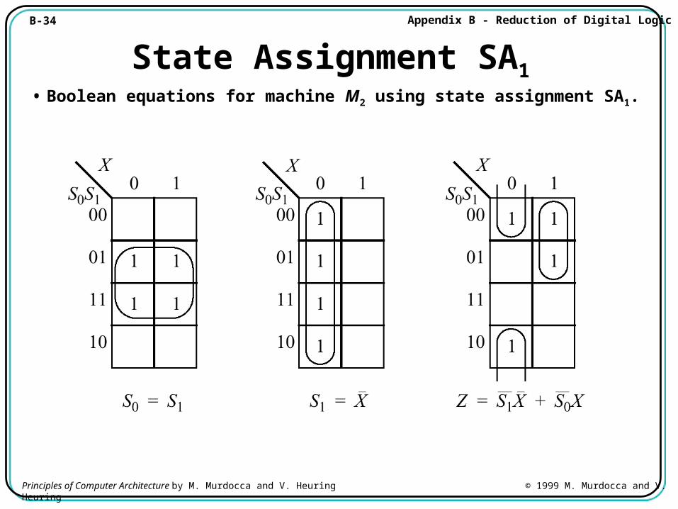
State Assignment SA1• Boolean equations for machine M2 using state assignment SA1.
B-35 Appendix B - Reduction of Digital Logic
Principles of Computer Architecture by M. Murdocca and V. Heuring © 1999 M. Murdocca and V. Heuring
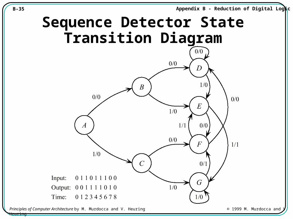
Sequence Detector State Transition Diagram
B-36 Appendix B - Reduction of Digital Logic
Principles of Computer Architecture by M. Murdocca and V. Heuring © 1999 M. Murdocca and V. Heuring
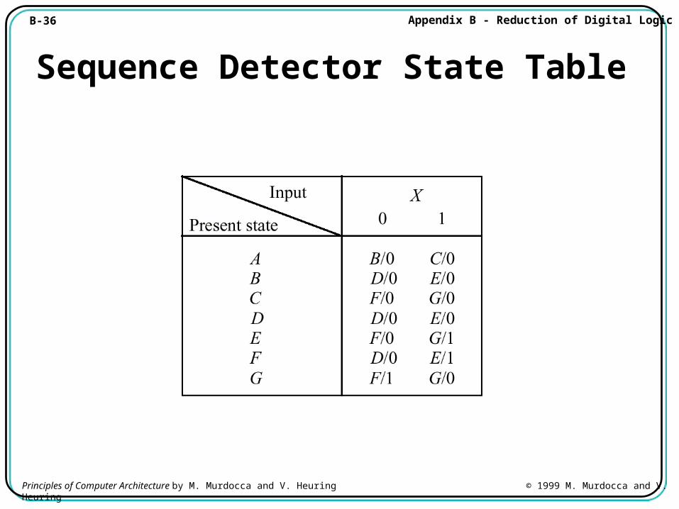
Sequence Detector State Table
B-37 Appendix B - Reduction of Digital Logic
Principles of Computer Architecture by M. Murdocca and V. Heuring © 1999 M. Murdocca and V. Heuring
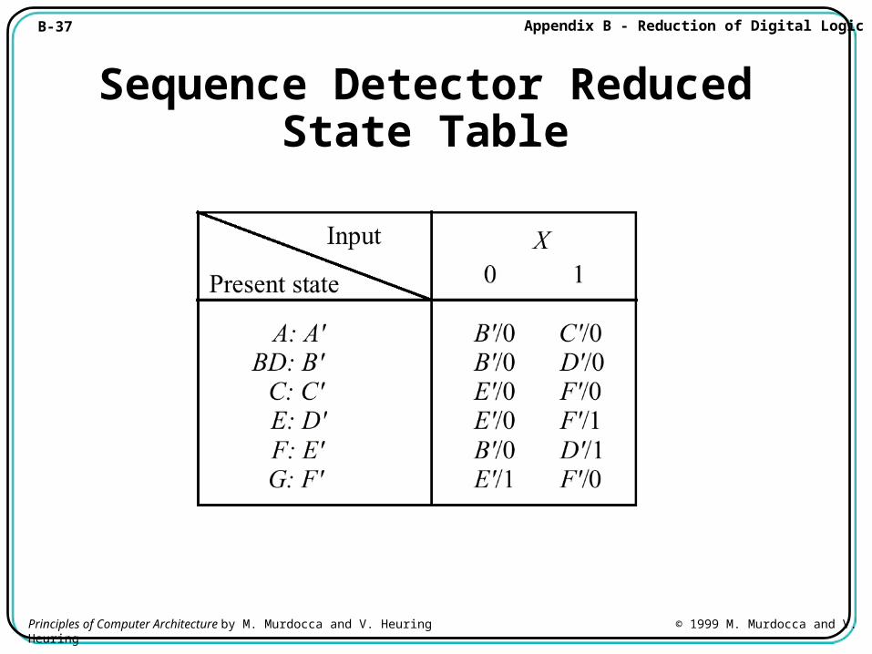
Sequence Detector Reduced State Table
B-38 Appendix B - Reduction of Digital Logic
Principles of Computer Architecture by M. Murdocca and V. Heuring © 1999 M. Murdocca and V. Heuring
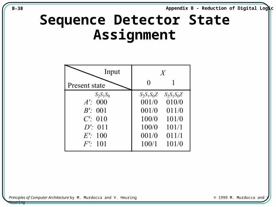
Sequence Detector State Assignment
B-39 Appendix B - Reduction of Digital Logic
Principles of Computer Architecture by M. Murdocca and V. Heuring © 1999 M. Murdocca and V. Heuring
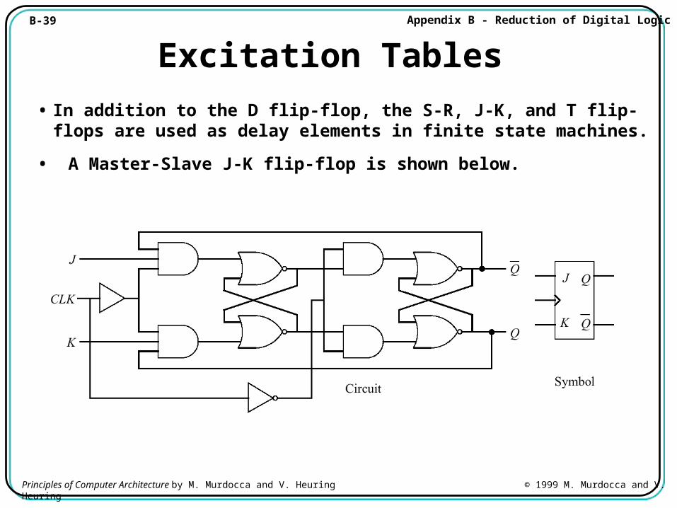
Excitation Tables
• In addition to the D flip-flop, the S-R, J-K, and T flip-flops are used as delay elements in finite state machines.
• A Master-Slave J-K flip-flop is shown below.
B-40 Appendix B - Reduction of Digital Logic
Principles of Computer Architecture by M. Murdocca and V. Heuring © 1999 M. Murdocca and V. Heuring
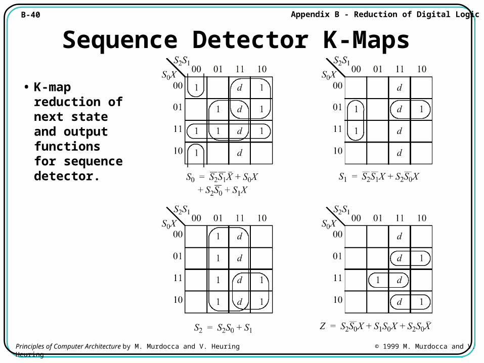
Sequence Detector K-Maps
• K-map reduction of next state and output functions for sequence detector.
B-41 Appendix B - Reduction of Digital Logic
Principles of Computer Architecture by M. Murdocca and V. Heuring © 1999 M. Murdocca and V. Heuring
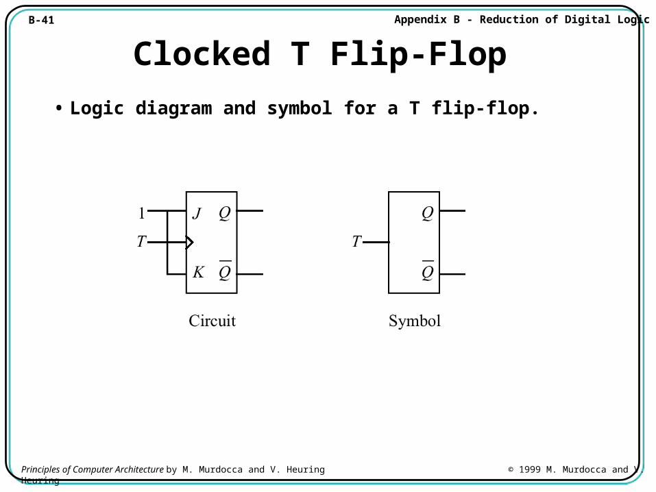
Clocked T Flip-Flop
• Logic diagram and symbol for a T flip-flop.
B-42 Appendix B - Reduction of Digital Logic
Principles of Computer Architecture by M. Murdocca and V. Heuring © 1999 M. Murdocca and V. Heuring
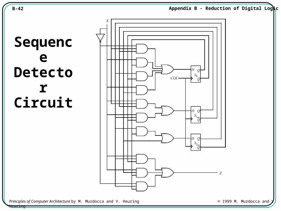
Sequence Detector Circuit
B-43 Appendix B - Reduction of Digital Logic
Principles of Computer Architecture by M. Murdocca and V. Heuring © 1999 M. Murdocca and V. Heuring
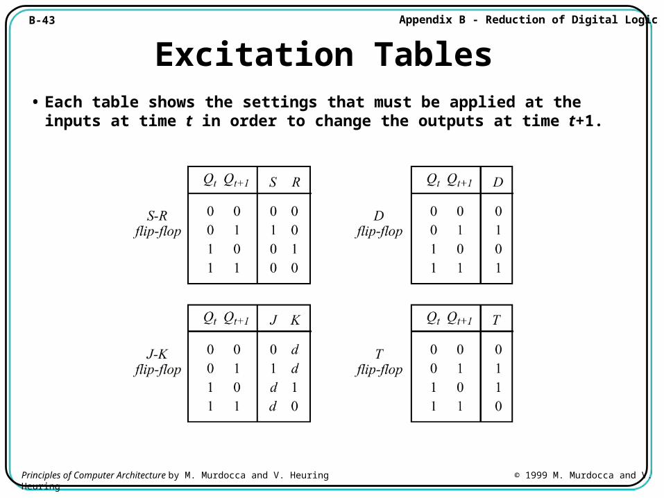
Excitation Tables• Each table shows the settings that must be applied at the inputs
at time t in order to change the outputs at time t+1.
B-44 Appendix B - Reduction of Digital Logic
Principles of Computer Architecture by M. Murdocca and V. Heuring © 1999 M. Murdocca and V. Heuring
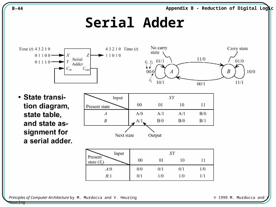
Serial Adder
B-45 Appendix B - Reduction of Digital Logic
Principles of Computer Architecture by M. Murdocca and V. Heuring © 1999 M. Murdocca and V. Heuring
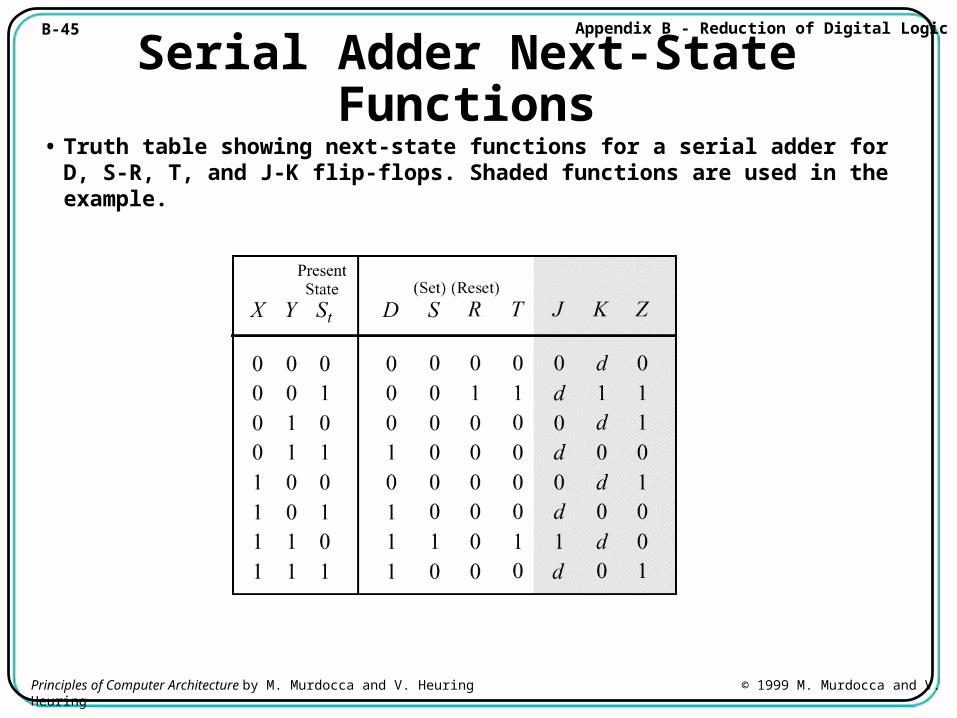
Serial Adder Next-State Functions• Truth table showing next-state functions for a serial adder for D, S-
R, T, and J-K flip-flops. Shaded functions are used in the example.
B-46 Appendix B - Reduction of Digital Logic
Principles of Computer Architecture by M. Murdocca and V. Heuring © 1999 M. Murdocca and V. Heuring
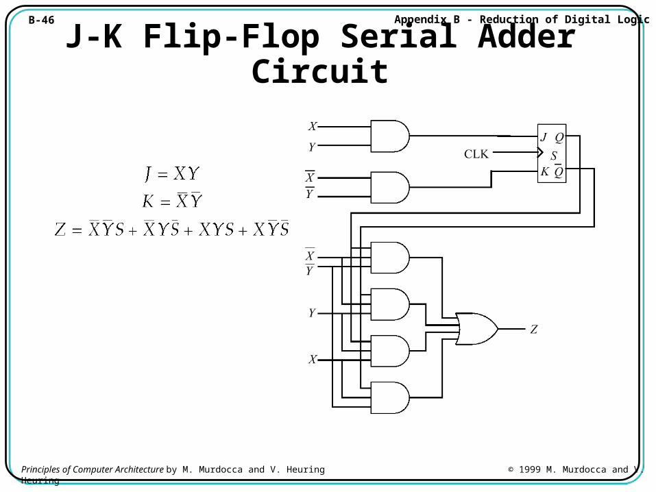
J-K Flip-Flop Serial Adder Circuit
B-47 Appendix B - Reduction of Digital Logic
Principles of Computer Architecture by M. Murdocca and V. Heuring © 1999 M. Murdocca and V. Heuring
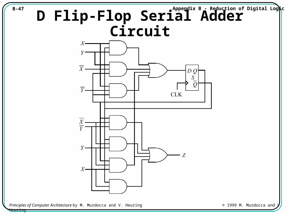
D Flip-Flop Serial Adder Circuit
B-48 Appendix B - Reduction of Digital Logic
Principles of Computer Architecture by M. Murdocca and V. Heuring © 1999 M. Murdocca and V. Heuring
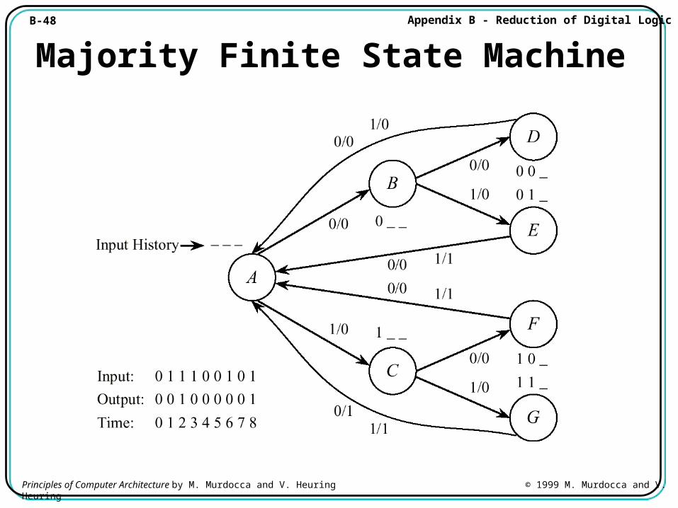
Majority Finite State Machine
B-49 Appendix B - Reduction of Digital Logic
Principles of Computer Architecture by M. Murdocca and V. Heuring © 1999 M. Murdocca and V. Heuring
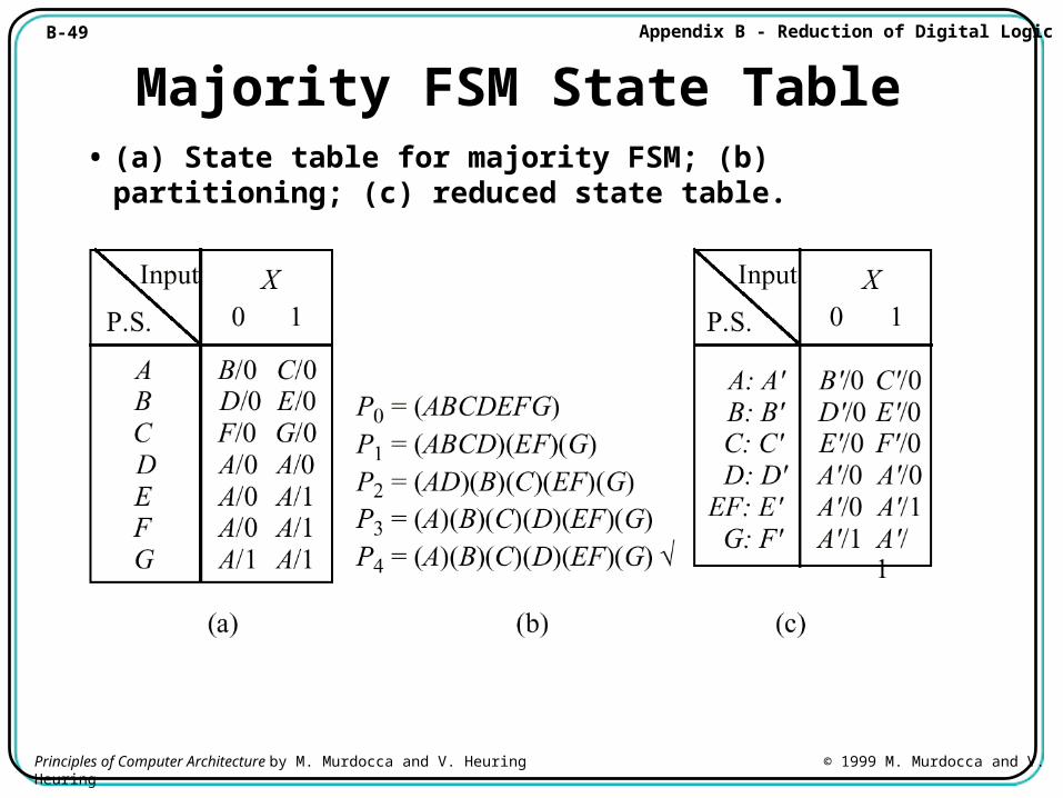
Majority FSM State Table• (a) State table for majority FSM; (b) partitioning; (c) reduced
state table.
B-50 Appendix B - Reduction of Digital Logic
Principles of Computer Architecture by M. Murdocca and V. Heuring © 1999 M. Murdocca and V. Heuring
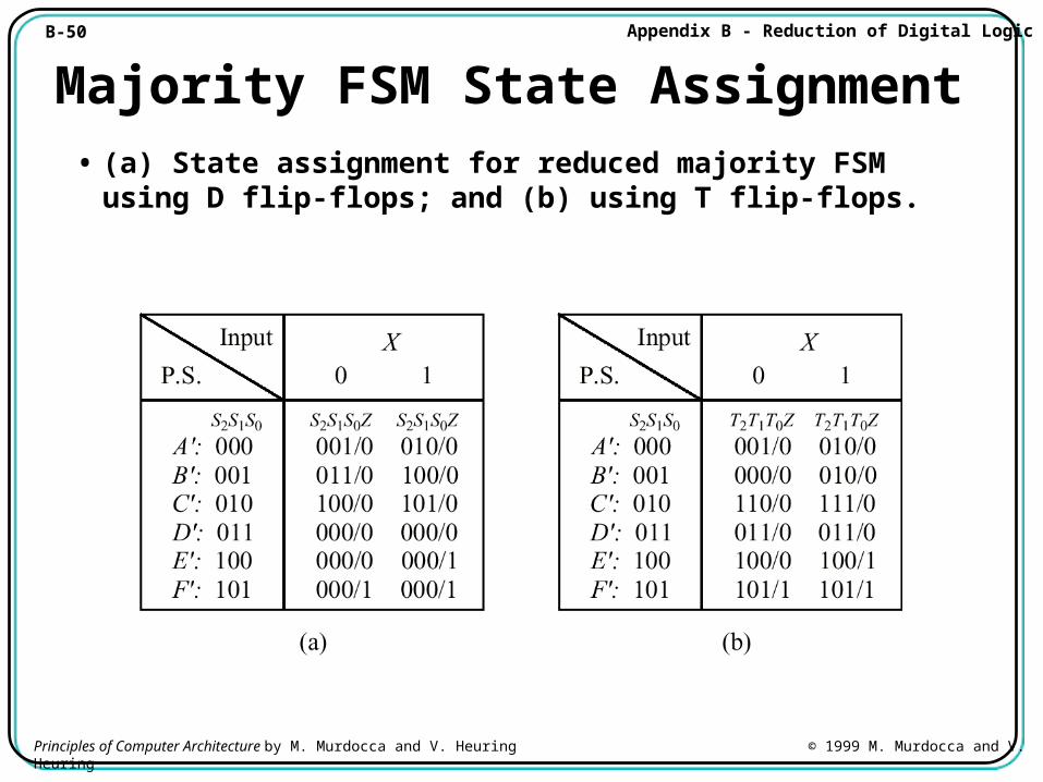
Majority FSM State Assignment• (a) State assignment for reduced majority FSM using D flip-
flops; and (b) using T flip-flops.
B-51 Appendix B - Reduction of Digital Logic
Principles of Computer Architecture by M. Murdocca and V. Heuring © 1999 M. Murdocca and V. Heuring
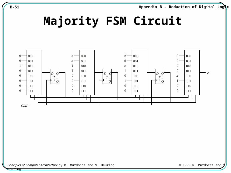
Majority FSM Circuit
![6-1 Parte 7 Comunicação. 6-2 Bibliografia [1] Miles J. Murdocca e Vincent P. Heuring, Introdução à Arquitetura de Computadores [2] Andrew S. Tanenbaum,](https://img.pdfslide.net/doc/110x75/5518b7d0550346881f8b520a/6-1-parte-7-comunicacao-6-2-bibliografia-1-miles-j-murdocca-e-vincent-p-heuring-introducao-a-arquitetura-de-computadores-2-andrew-s-tanenbaum.jpg)


![Parte 5 Entrada e Saída - gerson.orgfree.comgerson.orgfree.com/index_arquivos/Parte5.pdf · [1] Miles J. Murdocca e Vincent P. Heuring, “Introdução à Arquitetura de Computadores”](https://img.pdfslide.net/doc/110x75/5c13be0c09d3f2f42a8d13c0/parte-5-entrada-e-saida-1-miles-j-murdocca-e-vincent-p-heuring-introducao.jpg)

![7-1 Parte 6 Otimizações da Arquitetura. 7-2 Bibliografia [1] Miles J. Murdocca e Vincent P. Heuring, “Introdução à Arquitetura de Computadores” [2] Andrew](https://img.pdfslide.net/doc/110x75/570638581a28abb8238fc342/7-1-parte-6-otimizacoes-da-arquitetura-7-2-bibliografia-1-miles-j-murdocca.jpg)


![4-1 Parte 4 Memória. 4-2 Bibliografia [1] Miles J. Murdocca e Vincent P. Heuring, “Introdução à Arquitetura de Computadores” [2] Notas de Aula do Prof](https://img.pdfslide.net/doc/110x75/570638461a28abb8238f31ab/4-1-parte-4-memoria-4-2-bibliografia-1-miles-j-murdocca-e-vincent-p-heuring.jpg)