Embed Size (px)
Citation preview

B I A S T E E 2 . 0
Reducing the Size of the Filtering Hardware
for Josephson Junction Qubit Experiments Using
Iron Powder Inductor Cores.
Daniel Staudigel

Table of Contents
Bias Tee 2.0 Daniel Staudigel 3Quantum Computer Basics 3Theory and Electronics of Josephson Junction Qubits 4Purpose of the Bias Tee 5Previous Design of the “Handwound” Bias Tee 6Problems with Hand-wound Design 8Design Considerations and Research for Updated Design 8Physics of “Iron Powder” Inductor Cores 12Toroidal Design Outline and Performance 12Concerns With New Design & Future Changes 14Conclusions 14
Appendix 1 - Construction Instructions 15Materials Required 15Steps 15
Appendix 2 - Enclosure Fabrication Drawing 16
Bias Tee 2.0 - Daniel Staudigel
2

Bias Tee 2.0Daniel Staudigel
Quantum Computer Basics
The purpose of quantum computing is to leverage the fundamentally parallel nature of quantum
mechanics to solve problems that would be much more time consuming using conventional
computers. The name is somewhat confusing given that the fundamental building block of
modern computers, the transistor, can only be understood in terms of quantum mechanics. The
reason why conventional machines, based on transistors, do not fully harness quantum
mechanics is that they deal with large numbers of electrons, and do not pay attention to the
fundamental quantities. In large part, deeper quantum mechanics is lost because transistors
usually operate at such high temperatures that the vast majority of quantum effects are no longer
visible on top of the thermal and other environmental noise sources.
For this reason quantum computers must be set in a “quiet” environment, with highly sensitive
measurement and addressing electronics. “Quiet” can mean a variety of factors; temperature and
electromagnetic noise must be isolated from the quantum computer in some way. Without this
isolation, energy from the environment will leak into the experiment or computation and disturb
the outcome. Like conventional computers, it is convenient to work in terms of two-level, binary
states. Conventional bits turn into quantum bits (qubits) in a quantum computer. Aside from a
carefully prepared, quiet environment, and a focus on two-level systems, quantum computers
come in a variety of shapes and sizes. Single-atom qubits use individual atoms whose electrons
are excited into higher states to convey information. Quantum dot qubits are a silicon wafer
equivalent of single-atom qubits. Spin 1/2 systems like polarized light or bare electrons are also
Bias Tee 2.0 - Daniel Staudigel
3

used in many experiments. Josephson junction qubits are based on an potential well generated in
a superconducting LC oscillator with a Josephson junction providing an anharmonic component.
Theory and Electronics of Josephson Junction Qubits
Josephson qubits work based on the potential
created by a nonlinear superconducting
oscillator. The operation of the qubit is
controlled by a few external inputs. The first
is the flux bias, which tunes the depth and
relationship of the potential wells in the
system. Microwaves excite higher energy
states, and are tuned to specific transitions. In
a harmonic oscillator, all transitions between
states have the same energy gap. In the nonlinear potential of the Josephson qubit, every
transition has slightly different frequency, allowing
them to be individually excited. Once the qubit is
excited into a higher state, a measure pulse is
applied, which depresses the potential barrier for a
brief time. During this time, higher states have a
much greater probability of tunneling through the
barrier, leaving them in the right well. Using a
SQUID, the x position of a state can be easily
measured (see figure 1).
Fig.1: Tuned Josephson Potential. Flux bias controls shape of potential well. Microwaves drive
transitions between states in well. Measure pulse allows tunneling of higher states, so they can be
read along the x-axis of the potential.
!"#$%&'"()*+',-",($.
/0$1-2*3456789:;%(1-*,%$"2(,('"2
<-$2=*>?.2-
+',-",($.2#$>-*@,?"-;A
BCDEF*&-$2?%-2*G*$G(2
H?""-.("I
Fig.2: Electronics of Josephson Qubit. The qubit is physically isolated to reduce noise.
The bias line is added to the measure pulse before going into the qubit.
!"#$% &'#( )*+,-.(%
/-&'0'(1.#0%2
Qubit
3%#(-4%+,-.(%#52+&'#(+.'5%61)&'5%+'5+&'#(+0%%+01+(%07-&'0+80'.09
:'#(;%%
Bias Tee 2.0 - Daniel Staudigel
4

Purpose of the Bias Tee
The electrical interface to the qubit
in use in the Martinis Lab falls into
one of several categories. The bias
tee adds two of these inputs in the
fridge, right before the signal enters
the qubit. The two lines in question
are a high frequency (up to about
300-500MHz, RFbias in Fig. 3) line,
and a low-frequency (bias, DCbias,
in Fig 3) line. The bias tee must
isolate the RF signal from the bias
line, so that the pulse shapes have
higher fidelity. The low-frequency
line is also high-power, whereas the microwave line is low-power. Tuning the bias voltages
must swing multiple qubits (on the same chip) between 200-500MHz, to bring multi-qubit
experiments into and out of resonance with each other. Once on or off resonance, the voltages
must be stable. This means that at best, the bias tee must be clean, quiet, and predictable enough
to keep voltage pulses stable to about 1 part in 500. Without this stability, the two qubits in a
multi-qubit experiment might drift into and out of resonance, causing unpredictable results.
Performance must be predictable enough to reliably bring pulses from their sources to the cold-
plate unchanged.
BiasTees
Fig. 3: Location of the bias tee in the wiring setup of the dilution refrigerator
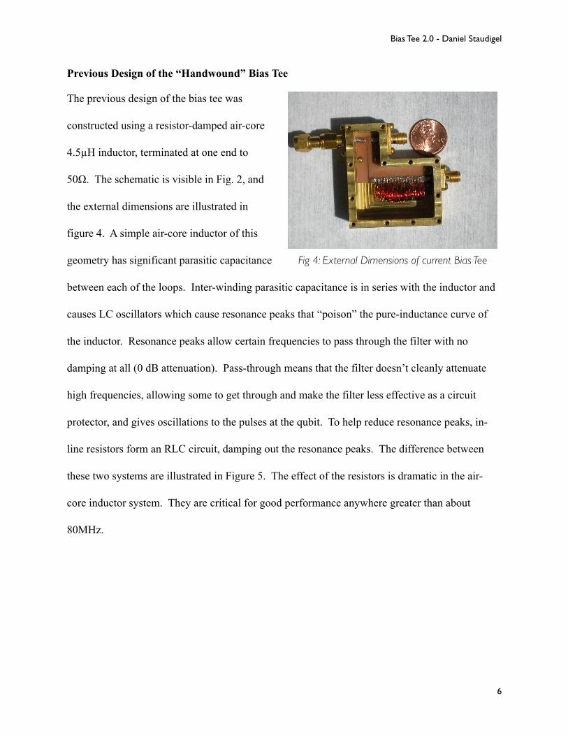
Previous Design of the “Handwound” Bias Tee
The previous design of the bias tee was
constructed using a resistor-damped air-core
4.5µH inductor, terminated at one end to
50Ω. The schematic is visible in Fig. 2, and
the external dimensions are illustrated in
figure 4. A simple air-core inductor of this
geometry has significant parasitic capacitance
between each of the loops. Inter-winding parasitic capacitance is in series with the inductor and
causes LC oscillators which cause resonance peaks that “poison” the pure-inductance curve of
the inductor. Resonance peaks allow certain frequencies to pass through the filter with no
damping at all (0 dB attenuation). Pass-through means that the filter doesn’t cleanly attenuate
high frequencies, allowing some to get through and make the filter less effective as a circuit
protector, and gives oscillations to the pulses at the qubit. To help reduce resonance peaks, in-
line resistors form an RLC circuit, damping out the resonance peaks. The difference between
these two systems are illustrated in Figure 5. The effect of the resistors is dramatic in the air-
core inductor system. They are critical for good performance anywhere greater than about
80MHz.
Fig 4: External Dimensions of current Bias Tee
Bias Tee 2.0 - Daniel Staudigel
6

The resonance peaks are clearly visible in the blue line, where several peaks come up to 0dB,
and several more are closer to -5dB. Since ideally -30dB is required for frequencies greater than
100MHz, the resonance peaks must be eliminated. This is done by using resistors in-between
groups of coils. The inter-coil resistors foil much of the inter-coil parasitic capacitance, reducing
the parasitic LC oscillations.
Fig.5: Effect of in-line resistors on filter performance. The blue line is without these in-line resistors, other lines are various models with in-line resistors. Notice the high resonance peaks that are a result of undamped parasitic
capacitance in the “handwound” inductor.
Bias Tee 2.0 - Daniel Staudigel
7

Problems with Hand-wound Design
The primary concern with the hand-wound bias tee design is physical size. There is limited size
on the cold-plate of the fridge. The limiting factor in the number of qubits that can be
simultaneously run in a single fridge is the footprint of auxiliary devices like the bias tee.
Reducing the external dimensions of the bias tee while keeping its electrical properties the same
will save a lot of space on the cold-plate, allowing more qubits to be run simultaneously.
Initially, an air-core was chosen because it is guaranteed to have no temperature dependence.
With this guarantee, it is easy to design the bias tee at room temperature, requiring very little
low-temperature testing before the design is finalized. Vacuum-cores (the refrigerator is
evacuated during cool-down) behave perfectly linearly with temperature, and thus make this
geometry easy to “debug”. The problem with vacuum cores is that, while linear in many
respects, it takes far more turns to get a desired inductance. With more turns comes more
parasitic capacitance, so while the design is easier from a temperature perspective, it is much
more difficult to get a nicely linear inductor at high frequencies.
Design Considerations and Research for Updated Design
Reduction of the physical size of the vacuum-core cylindrical inductor was the primary goal in
the design process of the new bias tee. A reduction in size of an order of magnitude is about all
that is mechanically reasonable. 3 SMA connectors determine the external dimensions of the
bias tee, and further shrinking of the inductor core will not reduce the external size of the bias
tee. Also, smaller cores will be difficult to construct and smaller resistors do not exist. Reducing
the size of the magnetics will require a different geometry and a magnetic material with a relative
permeability of about 10 or so, to reduce the size by a similar factor. In choosing a magnetic

material, temperature independence is a crucial variable. Many magnetic materials do not retain
their magnetic properties to low temperatures (especially those with high relative permeabilities).
The other primary concern will be minimizing the LC resonance peaks, in the same way that it
was for the previous design.
The most important part of the
research that went into the
design of the updated bias tee is
the temperature dependence
work. A wide variety of
materials are available
commercially for toroidal
inductor cores. They vary
greatly in relative permeability, and one with suitable temperature stability is critical to a
working bias tee. Since no data exists in the specifications for the inductor cores about 4K
performance, let alone 25mK performance, we must perform these experiments ourselves.
To do so, a properly terminated experiment mount was constructed and tested at room
temperature, in liquid helium (77K), and in liquid helium (4K). If temperature stability was good
at 77K, and at 4K, the cores were tested in a different mount at approximately 100mK in a
adiabatic demagnetization refrigerator. Once tested successfully in this fridge, they were
mounted in the final brass housing, and placed in the dilution refrigerator as bias tees, where
their true performance was verified.
Fig. 6: Poor temperature independence. Inductance drops markedly at 77K, compared to 300K. This is not an ideal sample.
Bias Tee 2.0 - Daniel Staudigel
9

Several models were found to have good temperature stability as well as sufficient relative
permeability to deliver sufficient inductance to be useful (Amidon™ Corporation models T25-2,
T25-6, and T25-10). In figure 7, temperature independence is clearly visible, as well as fairly
high LC resonance peaks. This test was done without any damping resistors.
Damping resistors were added to remove resonances, as well as to reduce parasitic capacitance.
Many different resistor configurations were tested, from sparse configurations (far fewer
resistors than turns) to dense configurations (1 less resistor than turns). In the dense
configuration, there is a resistor bridge between each of the turns, making a resistive path
entirely bypassing the inductor.
Fig. 7: Good Temperature Independence in T25-2 model Amidon™ iron powder toroid. Inductance does not change measurably between 300K
(red) and 100mK (blue).
Bias Tee 2.0 - Daniel Staudigel
10

In figure 8 the damping effect of the resistors is illustrated. In this experiment, the LC resonant
peak is not moved much by the addition of resistors, but this will be addressed in the final
design. Choice of resistor value affects the height of this peak.
Fig. 8: Effects of Resistors. The curve without resistors (red) transitioning (black) to the dense configuration of resistors (blue) shows the effects of resistors.
Bias Tee 2.0 - Daniel Staudigel
11

Physics of “Iron Powder” Inductor Cores
Based on some of the the papers that were
consulted about the design of the toroidal
“carbonyl iron powder” inductor cores, the
makeup of these cores appears to be relatively
straightforward. Iron powders of various
compositions (depending on the make and
model of the core) are ground into spheres of
approximately one cell of magnetism. The
spheres are pressed with an inert binder into the desired shape (for us, 0.25in outer diameter
toruses). Each sphere is approximately one magnetic cell, which has a given magnetic moment.
In the presence of an external magnetic field, all of the magnetic moments deflect slightly and
increase the overall field by an order of magnitude, giving them a relative permeability of 10.
This mechanism gives this design relatively good temperature independence and linearity, both
qualities that are important to us.
Toroidal Design Outline and Performance
The toroidal design is centered around a 0.25 inch (outer diameter) toroidal iron powder inductor.
It is wound with 12 winds of 28AWG copper magnet wire, stripped at the ends, and around the
perimeter of the torus. Eleven 10Ω resistors are soldered around the perimeter, between each of
the stripped turns. These damp out parasitic capacitance that would otherwise cause LC
oscillations.
!
Fig. 9: External B field applies small torque on each magnetic cell, causing slight deflection and a
corresponding increase in magnetic field.

The final torus is housed in a small brass enclosure on which the 3 SMA connectors are mounted.
The copper box is closed and mounted to the cold-plate.
The toroidal design performs very well. It has good temperature stability, linear inductance, and
no significant resonance peaks. It compares favorably with the vacuum-core design, especially
given its far smaller package dimensions. In figure 10, the effects of damping resistors are
shown in the brass enclosure. The reduction of LC resonances is much better illustrated in Fig.
10 than in Fig. 9, due to the choice of the resistors.
Fig. 10: Final Performance Criteria. Enclosed, terminated, and damped (red) shows best performance. Enclosed and damped (green) shows better linearity and less LC resonance than enclosed and
undamped (blue). The same pattern can be seen in the unenclosed version (purple/teal).
Bias Tee 2.0 - Daniel Staudigel
13

Concerns With New Design & Future Changes
The main concern with the first toroidal design is that the microwave performance is somewhat
degraded on the thru-line. Because of the initial design of the box, the high frequency line is not
matched perfectly to 50Ω. The non-matched microwave line means that high-frequency
throughput is suboptimal. To match this line better will require more careful microwave
engineering of the box. While not important for the current application of the bias tee,
improvements of the microwave performance would allow the microwave pulses as well as the
measure pulses to be added to the flux bias line before all entering the qubit in the same inductor.
Conclusions
The new bias tee box was a success, performance
was improved over the previous model in the low
frequency linearity, with some sacrifices in the
higher frequency attenuation. The box is
significantly smaller than the previous iteration
(see figure 11). With some more work, the
performance can be improved even more, but the
desired characteristics have all been borne out in the final design.
Fig. 11: Bias Tees. New design on the right.
Bias Tee 2.0 - Daniel Staudigel
14

Appendix 1 - Construction Instructions
Materials Required
1. Bias tee enclosure (see appendix 2) and lid
2. Amidon™ T25-2 iron powder toroid inductor core
3. 28AWG magnet wire
4. 11 10Ω NiCr 0402 resistors
5. 2 female SMA connectors
6. 1 male (screw-on) SMA connector
7. 6 2-56UNC and 13 0-80 UNC brass screws
8. 1 50Ω NiCr resistor (or 2 100Ω) and brass strapping
Steps
1. Wrap the inductor core with 12 turns of 28AWG magnet wire. Windings should be evenly spaced.
2. Strip the ends and around the perimeter of each of the turns, making sure to strip on all three sides of the wire (excluding the side touching the toroid).
3. Solder resistors in between each turn (where the wire has been stripped).
4. Mount SMA connectors to brass box with 2-56UNC screws
5. Solder inductor to appropriate SMA connectors.
6. Solder 50Ω to brass strapping and connect flux input line via 50Ω to the grounding 0-80 screw in the lower right corner of the inductor box.
7. Solder through-line together
8. Close box with 0-80UNC screws.
Bias Tee 2.0 - Daniel Staudigel
15
Fig A1: Final Construction

Appendix 2 - Enclosure Fabrication Drawing
1
1
2
2
A A
B B
0.80
1.25
0.35
0.60
1.05
0.050.05
.161 TYP
1/16 in2-56 UNC
THRU (TYP)
.10
.10
.10
.10
0.40
0.250.55
0.75
0.55
0.88
1.20
0.05
0.25 0.25
0.400.40
0.17
0.15
0.40
0.65
0.30
.255
.168
0.05
R1/16 in
0.40
0.100.30
.163
0.64
.163
0.18
0.53
0.20
0-80 UNF - 2B
0-80 UNF - 2B
0-80 UNF - 2B
Bias Tee 2.0 - Daniel Staudigel
16


![arXiv:1011.0772v1 [quant-ph] 2 Nov 2010 · 2018. 10. 31. · BSMs on qubit jTi 1 with qubit 3, and qubit jCi 2 with qubit 5. Based on the results of the BSMs, 16 possible Pauli corrections](https://img.pdfslide.net/doc/110x75/60b25df3e4684b238c4028dc/arxiv10110772v1-quant-ph-2-nov-2010-2018-10-31-bsms-on-qubit-jti-1-with.jpg)


![[201702]Qubit Security Pitch deck](https://img.pdfslide.net/doc/110x75/58ac060b1a28abb6718b67c9/201702qubit-security-pitch-deck.jpg)