Embed Size (px)
Citation preview

BP/N LS10036-000FL-E:B ECN 15-351
Document LS10036-000FL-E9/14/2015 Rev:
SWIFT®Smart Wireless Integrated Fire Technology
Instruction Manual
2 SWIFT® Smart Wireless Integrated Fire Technology Manual — P/N LS10036-000FL-E:B 9/14/2015
Fire Alarm & Emergency Communication System LimitationsWhile a life safety system may lower insurance rates, it is not a substitute for life and property insurance!An automatic fire alarm system—typically made up of smoke detectors, heat detectors, manual pull stations, audible warning devices, and a fire alarm control panel (FACP) with remote notifi-cation capability—can provide early warning of a developing fire. Such a system, however, does not assure protection against property damage or loss of life resulting from a fire.
An emergency communication system—typically made up of an automatic fire alarm system (as described above) and a life safety communication system that may include an autonomous control unit (ACU), local operating console (LOC), voice commu-nication, and other various interoperable communication meth-ods—can broadcast a mass notification message. Such a system, however, does not assure protection against property damage or loss of life resulting from a fire or life safety event.
The Manufacturer recommends that smoke and/or heat detectors be located throughout a protected premises following the recommendations of the current edition of the National Fire Protection Association Standard 72 (NFPA 72), manufacturer's recommendations, State and local codes, and the recommendations contained in the Guide for Proper Use of System Smoke Detectors, which is made available at no charge to all installing dealers. This document can be found at http://www.systemsensor.com/appguides/. A study by the Federal Emergency Management Agency (an agency of the United States government) indicated that smoke detectors may not go off in as many as 35% of all fires. While fire alarm systems are designed to provide early warning against fire, they do not guarantee warning or protection against fire. A fire alarm system may not provide timely or adequate warning, or simply may not function, for a variety of reasons:
Smoke detectors may not sense fire where smoke cannot reach the detectors such as in chimneys, in or behind walls, on roofs, or on the other side of closed doors. Smoke detectors also may not sense a fire on another level or floor of a building. A second-floor detector, for example, may not sense a first-floor or basement fire.
Particles of combustion or “smoke” from a developing fire may not reach the sensing chambers of smoke detectors because:
• Barriers such as closed or partially closed doors, walls, chim-neys, even wet or humid areas may inhibit particle or smoke flow.
• Smoke particles may become “cold,” stratify, and not reach the ceiling or upper walls where detectors are located.
• Smoke particles may be blown away from detectors by air outlets, such as air conditioning vents.
• Smoke particles may be drawn into air returns before reach-ing the detector.
The amount of “smoke” present may be insufficient to alarm smoke detectors. Smoke detectors are designed to alarm at var-ious levels of smoke density. If such density levels are not cre-ated by a developing fire at the location of detectors, the detectors will not go into alarm.
Smoke detectors, even when working properly, have sensing limitations. Detectors that have photoelectronic sensing cham-bers tend to detect smoldering fires better than flaming fires, which have little visible smoke. Detectors that have ionizing-type sensing chambers tend to detect fast-flaming fires better than smoldering fires. Because fires develop in different ways and are often unpredictable in their growth, neither type of detector is necessarily best and a given type of detector may not provide adequate warning of a fire.
Smoke detectors cannot be expected to provide adequate warn-ing of fires caused by arson, children playing with matches (especially in bedrooms), smoking in bed, and violent explosions
(caused by escaping gas, improper storage of flammable materi-als, etc.).
Heat detectors do not sense particles of combustion and alarm only when heat on their sensors increases at a predetermined rate or reaches a predetermined level. Rate-of-rise heat detec-tors may be subject to reduced sensitivity over time. For this reason, the rate-of-rise feature of each detector should be tested at least once per year by a qualified fire protection specialist. Heat detectors are designed to protect property, not life.
IMPORTANT! Smoke detectors must be installed in the same room as the control panel and in rooms used by the system for the connection of alarm transmission wiring, communications, signaling, and/or power. If detectors are not so located, a devel-oping fire may damage the alarm system, compromising its abil-ity to report a fire.
Audible warning devices such as bells, horns, strobes, speakers and displays may not alert people if these devices are located on the other side of closed or partly open doors or are located on another floor of a building. Any warning device may fail to alert people with a disability or those who have recently consumed drugs, alcohol, or medication. Please note that:
• An emergency communication system may take priority over a fire alarm system in the event of a life safety emergency.
• Voice messaging systems must be designed to meet intelligi-bility requirements as defined by NFPA, local codes, and Authorities Having Jurisdiction (AHJ).
• Language and instructional requirements must be clearly dis-seminated on any local displays.
• Strobes can, under certain circumstances, cause seizures in people with conditions such as epilepsy.
• Studies have shown that certain people, even when they hear a fire alarm signal, do not respond to or comprehend the meaning of the signal. Audible devices, such as horns and bells, can have different tonal patterns and frequencies. It is the property owner's responsibility to conduct fire drills and other training exercises to make people aware of fire alarm signals and instruct them on the proper reaction to alarm sig-nals.
• In rare instances, the sounding of a warning device can cause temporary or permanent hearing loss.
A life safety system will not operate without any electrical power. If AC power fails, the system will operate from standby batteries only for a specified time and only if the batteries have been properly maintained and replaced regularly.
Equipment used in the system may not be technically compat-ible with the control panel. It is essential to use only equipment listed for service with your control panel.
Telephone lines needed to transmit alarm signals from a prem-ises to a central monitoring station may be out of service or tem-porarily disabled. For added protection against telephone line failure, backup radio transmission systems are recommended.
The most common cause of life safety system malfunction is inadequate maintenance. To keep the entire life safety system in excellent working order, ongoing maintenance is required per the manufacturer's recommendations, and UL and NFPA stan-dards. At a minimum, the requirements of NFPA 72 shall be fol-lowed. Environments with large amounts of dust, dirt, or high air velocity require more frequent maintenance. A maintenance agreement should be arranged through the local manufacturer's representative. Maintenance should be scheduled monthly or as required by National and/or local fire codes and should be per-formed by authorized professional life safety system installers only. Adequate written records of all inspections should be kept.
Limit-D-1-2013
SWIFT® Smart Wireless Integrated Fire Technology Manual — P/N LS10036-000FL-E:B 9/14/2015 3
Installation PrecautionsAdherence to the following will aid in problem-free installation with long-term reliability:WARNING - Several different sources of power can be connected to the fire alarm control panel. Disconnect all sources of power before servicing. Control unit and associ-ated equipment may be damaged by removing and/or insert-ing cards, modules, or interconnecting cables while the unit is energized. Do not attempt to install, service, or operate this unit until manuals are read and understood.
CAUTION - System Re-acceptance Test after Software Changes: To ensure proper system operation, this product must be tested in accordance with NFPA 72 after any pro-gramming operation or change in site-specific software. Re-acceptance testing is required after any change, addition or deletion of system components, or after any modification, repair or adjustment to system hardware or wiring. All compo-nents, circuits, system operations, or software functions known to be affected by a change must be 100% tested. In addition, to ensure that other operations are not inadvertently affected, at least 10% of initiating devices that are not directly affected by the change, up to a maximum of 50 devices, must also be tested and proper system operation verified.
This system meets NFPA requirements for operation at 0-49º C/32-120º F and at a relative humidity 93% ± 2% RH (non-condensing) at 32°C ± 2°C (90°F ± 3°F). However, the useful life of the system's standby batteries and the electronic com-ponents may be adversely affected by extreme temperature ranges and humidity. Therefore, it is recommended that this system and its peripherals be installed in an environment with a normal room temperature of 15-27º C/60-80º F.
Verify that wire sizes are adequate for all initiating and indi-cating device loops. Most devices cannot tolerate more than a 10% I.R. drop from the specified device voltage.
Like all solid state electronic devices, this system may operate erratically or can be damaged when subjected to light-ning induced transients. Although no system is completely immune from lightning transients and interference, proper grounding will reduce susceptibility. Overhead or outside aerial wiring is not recommended, due to an increased susceptibility to nearby lightning strikes. Consult with the Technical Ser-vices Department if any problems are anticipated or encoun-tered.
Disconnect AC power and batteries prior to removing or inserting circuit boards. Failure to do so can damage circuits.
Remove all electronic assemblies prior to any drilling, filing, reaming, or punching of the enclosure. When possible, make all cable entries from the sides or rear. Before making modifi-cations, verify that they will not interfere with battery, trans-former, or printed circuit board location.
Do not tighten screw terminals more than 9 in-lbs. Over-tightening may damage threads, resulting in reduced terminal contact pressure and difficulty with screw terminal removal.
This system contains static-sensitive components. Always ground yourself with a proper wrist strap before han-dling any circuits so that static charges are removed from the body. Use static suppressive packaging to protect electronic assemblies removed from the unit.
Follow the instructions in the installation, operating, and pro-gramming manuals. These instructions must be followed to avoid damage to the control panel and associated equipment. FACP operation and reliability depend upon proper installation.
Precau-D1-9-2005
FCC WarningWARNING: This equipment generates, uses, and can radiate radio frequency energy and if not installed and used in accordance with the instruction manual may cause interference to radio communications. It has been tested and found to comply with the limits for class A computing devices pursuant to Subpart B of Part 15 of FCC Rules, which is designed to provide reasonable protection against such interference when devices are operated in a commercial environment. Operation of this equipment in a residential area is likely to cause interfer-ence, in which case the user will be required to correct the interference at his or her own expense.
Canadian Requirements
This digital apparatus does not exceed the Class A limits for radiation noise emissions from digital apparatus set out in the Radio Interference Regulations of the Cana-dian Department of Communications.
Le present appareil numerique n'emet pas de bruits radi-oelectriques depassant les limites applicables aux appa-reils numeriques de la classe A prescrites dans le Reglement sur le brouillage radioelectrique edicte par le ministere des Communications du Canada.
LiteSpeed™ and Lite-Connect™ are trademarks; and Fire-Lite® Alarms and SWIFT® are registered trademarks of Honeywell International Inc. Microsoft®and Windows® are registered trademarks of the Microsoft Corporation. Chrome™ and Google™ are trademarks of Google Inc.
©2015 by Honeywell International Inc. All rights reserved. Unauthorized use of this document is strictly prohibited.
4 SWIFT® Smart Wireless Integrated Fire Technology Manual — P/N LS10036-000FL-E:B 9/14/2015
Software DownloadsIn order to supply the latest features and functionality in fire alarm and life safety technology to our customers, we make frequent upgrades to the embedded software in our products. To ensure that you are installing and programming the latest features, we strongly recommend that you download the most current version of software for each product prior to commissioning any system. Contact Technical Support with any questions about software and the appropriate version for a specific application.
Documentation FeedbackYour feedback helps us keep our documentation up-to-date and accurate. If you have any comments or suggestions about our online Help or printed manuals, you can email us.
Please include the following information:
•Product name and version number (if applicable)
•Printed manual or online Help
•Topic Title (for online Help)
•Page number (for printed manual)
•Brief description of content you think should be improved or corrected
•Your suggestion for how to correct/improve documentation
Send email messages to:
Please note this email address is for documentation feedback only. If you have any technical issues, please contact Technical Services.
SWIFT® Smart Wireless Integrated Fire Technology Manual — P/N LS10036-000FL-E:B 9/14/2015 5
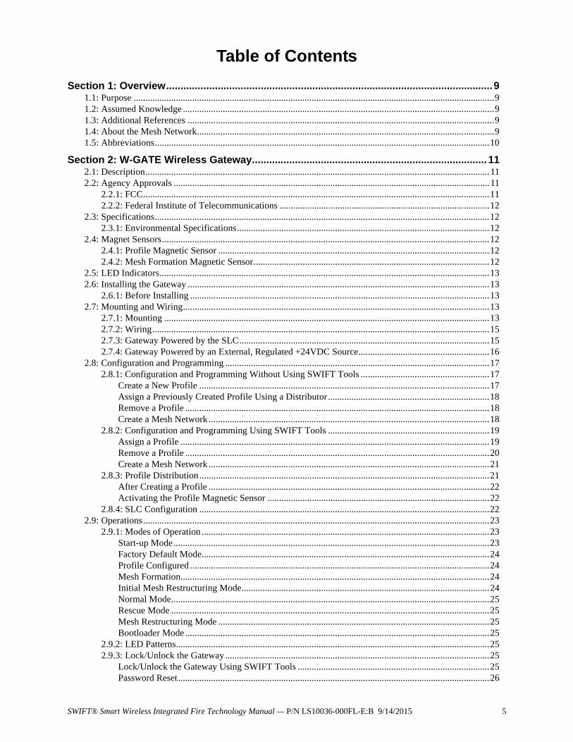
Table of Contents
Section 1: Overview..................................................................................................................91.1: Purpose ..........................................................................................................................................................91.2: Assumed Knowledge .....................................................................................................................................91.3: Additional References ...................................................................................................................................91.4: About the Mesh Network...............................................................................................................................91.5: Abbreviations...............................................................................................................................................10
Section 2: W-GATE Wireless Gateway.................................................................................. 112.1: Description...................................................................................................................................................112.2: Agency Approvals .......................................................................................................................................11
2.2.1: FCC....................................................................................................................................................112.2.2: Federal Institute of Telecommunications ..........................................................................................12
2.3: Specifications...............................................................................................................................................122.3.1: Environmental Specifications............................................................................................................12
2.4: Magnet Sensors............................................................................................................................................122.4.1: Profile Magnetic Sensor ....................................................................................................................122.4.2: Mesh Formation Magnetic Sensor.....................................................................................................12
2.5: LED Indicators.............................................................................................................................................132.6: Installing the Gateway .................................................................................................................................13
2.6.1: Before Installing ................................................................................................................................132.7: Mounting and Wiring...................................................................................................................................13
2.7.1: Mounting ...........................................................................................................................................132.7.2: Wiring................................................................................................................................................152.7.3: Gateway Powered by the SLC...........................................................................................................152.7.4: Gateway Powered by an External, Regulated +24VDC Source........................................................16
2.8: Configuration and Programming .................................................................................................................172.8.1: Configuration and Programming Without Using SWIFT Tools .......................................................17
Create a New Profile ............................................................................................................................17Assign a Previously Created Profile Using a Distributor.....................................................................18Remove a Profile ..................................................................................................................................18Create a Mesh Network ........................................................................................................................18
2.8.2: Configuration and Programming Using SWIFT Tools .....................................................................19Assign a Profile ....................................................................................................................................19Remove a Profile ..................................................................................................................................20Create a Mesh Network ........................................................................................................................21
2.8.3: Profile Distribution ............................................................................................................................21After Creating a Profile ........................................................................................................................22Activating the Profile Magnetic Sensor ...............................................................................................22
2.8.4: SLC Configuration ............................................................................................................................222.9: Operations....................................................................................................................................................23
2.9.1: Modes of Operation ...........................................................................................................................23Start-up Mode.......................................................................................................................................23Factory Default Mode...........................................................................................................................24Profile Configured ................................................................................................................................24Mesh Formation....................................................................................................................................24Initial Mesh Restructuring Mode..........................................................................................................24Normal Mode........................................................................................................................................25Rescue Mode ........................................................................................................................................25Mesh Restructuring Mode ....................................................................................................................25Bootloader Mode ..................................................................................................................................25
2.9.2: LED Patterns......................................................................................................................................252.9.3: Lock/Unlock the Gateway .................................................................................................................25
Lock/Unlock the Gateway Using SWIFT Tools ..................................................................................25Password Reset.....................................................................................................................................26

Table of Contents
6 SWIFT® Smart Wireless Integrated Fire Technology Manual — P/N LS10036-000FL-E:B 9/14/2015
2.9.4: Weak Link Trouble Reporting...........................................................................................................26Disable Trouble Reporting at the Gateway Using SWIFT Tools.........................................................26
2.9.5: Collapse Network Command.............................................................................................................27Collapse Mesh Network Using SWIFT Tools......................................................................................27
2.9.6: Silence Network Command...............................................................................................................28Silence Mesh Network Using SWIFT Tools ........................................................................................28
2.9.7: Multiple Wireless Sensor Network Installation Restrictions.............................................................292.9.8: Avoiding RF Interference ..................................................................................................................30
Section 3: W-DIS-D Wireless Display Driver ........................................................................ 313.1: Description...................................................................................................................................................313.2: Agency Approvals ......................................................................................................................................32
3.2.1: FCC....................................................................................................................................................323.2.2: Federal Institute of Telecommunications ..........................................................................................32
3.3: Specifications ...............................................................................................................................................323.3.1: Environmental Specifications ............................................................................................................32
3.4: Magnetic Sensors .........................................................................................................................................333.5: Display Driver LED Indicators ....................................................................................................................333.6: Mounting & Wiring......................................................................................................................................33
3.6.1: Mounting............................................................................................................................................333.6.2: Wiring ................................................................................................................................................34
3.7: Configuration ...............................................................................................................................................353.7.1: Assign a Profile..................................................................................................................................36
Assigning a Profile Without Using SWIFT Tools................................................................................36Assign a Profile Using SWIFT Tools...................................................................................................36
3.7.2: Mesh Formation.................................................................................................................................373.7.3: Removing Profiles .............................................................................................................................37
Restoring to Factory Default Without Using SWIFT Tools.................................................................37Restoring to Factory Default Using SWIFT Tools...............................................................................37
3.8: ANN-80-W Configuration ...........................................................................................................................383.9: Display Driver Operations ...........................................................................................................................39
3.9.1: Modes of Operation Not in a Mesh Network ....................................................................................39Bootloader.............................................................................................................................................39Factory Default .....................................................................................................................................39Profile Configured ................................................................................................................................39
3.9.2: Modes of Operation as a Mesh Participant........................................................................................40Mesh Formation Mode .........................................................................................................................40Initial Mesh Restructuring Mode..........................................................................................................40Normal Mode........................................................................................................................................40Rescue Mode ........................................................................................................................................40
3.9.3: SLC Operation ...................................................................................................................................403.9.4: LED Patterns......................................................................................................................................40
3.10: ANN-80-W Operations ..............................................................................................................................403.10.1: Annunciator Control Buttons and Visual Indicators .......................................................................413.10.2: Audible Indicators ...........................................................................................................................423.10.3: Event Messages ...............................................................................................................................42
RF Comm Loss .....................................................................................................................................42Trouble Wireless Mesh Formation In Progress ....................................................................................42Low Battery Event................................................................................................................................42Trouble Jamming Event........................................................................................................................42Trouble Duplicate Address ...................................................................................................................42Trouble Class A Missing 2nd Link.......................................................................................................43Trouble Wireless Gateway Initializing.................................................................................................43System Normal .....................................................................................................................................43Supervisory Tamper..............................................................................................................................43Trouble Weak Link Low Signal Strength.............................................................................................43Key Bus Trouble...................................................................................................................................43

Table of Contents
SWIFT® Smart Wireless Integrated Fire Technology Manual — P/N LS10036-000FL-E:B 9/14/2015 7
Capacity Exceeded ...............................................................................................................................43Maximum Gateways.............................................................................................................................43RF Device No Answer..........................................................................................................................43
3.10.4: Clearing messages ...........................................................................................................................43
Section 4: Wireless Devices .................................................................................................. 454.1: Description...................................................................................................................................................454.2: Agency Approvals .......................................................................................................................................45
4.2.1: FCC....................................................................................................................................................454.2.2: Federal Institute of Telecommunications ..........................................................................................46
4.3: Specifications...............................................................................................................................................464.4: Installing, Mounting, and Wiring Devices...................................................................................................464.5: Configuration and Programming .................................................................................................................46
4.5.1: Assigning Profiles .............................................................................................................................46Assigning a Profile to a Device (Detector or Module) Using a Gateway or Distributor .....................46Assigning a Profile Using SWIFT Tools..............................................................................................48
4.5.2: Distributor Mode ...............................................................................................................................49Converting a Device into a Distributor ................................................................................................49Converting a Distributor Back into a Device .......................................................................................49
4.5.3: Mesh Formation.................................................................................................................................49Repeater ................................................................................................................................................50
4.5.4: Restoring a Device to Factory Default ..............................................................................................50Removing Profiles Without Using SWIFT Tools ................................................................................50Removing a Profile Using SWIFT Tools .............................................................................................50
4.6: Device Operations .......................................................................................................................................514.6.1: Modes of Operation ...........................................................................................................................51
Factory Default Mode...........................................................................................................................51Site Survey Mode .................................................................................................................................51Profile Assigned Mode .........................................................................................................................52Bootloader Mode ..................................................................................................................................52Distributor Mode ..................................................................................................................................52Mesh Participant Modes .......................................................................................................................52
4.6.2: LED Indicators ..................................................................................................................................52
Section 5: USB Adapter.......................................................................................................... 545.1: Introduction..................................................................................................................................................545.2: Agency Approvals ......................................................................................................................................54
5.2.1: FCC....................................................................................................................................................545.2.2: Federal Institute of Telecommunications ..........................................................................................54
5.3: Specifications...............................................................................................................................................555.3.1: Electrical Specifications ....................................................................................................................555.3.2: Serial Communication Specification .................................................................................................555.3.3: Mechanical Specifications.................................................................................................................555.3.4: Environmental Specifications............................................................................................................55
5.4: Driver Installation ........................................................................................................................................55
Appendix A: SWIFT Tools ...................................................................................................... 59A.1: Description..................................................................................................................................................59A.2: Launching SWIFT Tools.............................................................................................................................59
A.2.1: Creating a New Jobsite .....................................................................................................................60A.2.2: Opening an Existing Jobsite .............................................................................................................61
Appendix B: Site Survey ........................................................................................................62B.1: Conduct a Site Survey.................................................................................................................................62
B.1.1: Link Quality Test ..............................................................................................................................62Basic Requirements of a Link Quality Test .........................................................................................62Conduct a Link Quality Test ................................................................................................................62Results of a Link Quality Test..............................................................................................................63

Table of Contents
8 SWIFT® Smart Wireless Integrated Fire Technology Manual — P/N LS10036-000FL-E:B 9/14/2015
After a Link Quality Test......................................................................................................................63B.1.2: RF Scan Test .....................................................................................................................................64
Conduct an RF Scan Test .....................................................................................................................64Status of an RF Scan Test.....................................................................................................................64
B.1.3: Retrieving Site Survey Results .........................................................................................................64
Appendix C: Troubleshooting and Testing .......................................................................... 66C.1: Troubleshooting...........................................................................................................................................66C.2: Testing the Gateway and Devices ...............................................................................................................68
C.2.1: Testing LED Indicators .....................................................................................................................68C.3: Testing the Wireless Network .....................................................................................................................68
C.3.1: Network Topology ............................................................................................................................69Parent-Child Devices ............................................................................................................................69Orphan Devices ....................................................................................................................................69Class A Compliance .............................................................................................................................69
C.3.2: History Events...................................................................................................................................69C.3.3: Network Snapshots ...........................................................................................................................69C.3.4: Network Statistics .............................................................................................................................69C.3.5: Device Attributes ..............................................................................................................................70
Appendix D: LED Indicators .................................................................................................. 71
Appendix E: Firmware Upgrade/Downgrade Instructions .................................................. 77E.1: W-USB Adapter Upgrade Procedure...........................................................................................................77E.2: Gateway Firmware Upgrade/Downgrade Procedure...................................................................................77E.3: Device Firmware Upgrade/Downgrade Procedure .....................................................................................78E.4: Display Driver Firmware Upgrade/Downgrade Procedure .........................................................................79
Index ........................................................................................................................................ 80
9 SWIFT® Smart Wireless Integrated Fire Technology Manual — P/N LS10036-000FL-E:B 9/14/2015
Section 1: Overview
1.1 PurposeThe SWIFT™ Network Manual provides an overview of the following:
• Wireless fire alarm system
• Instructions for installing and configuring the wireless devices
• Information on monitoring the status of the wireless devices
• Removal and replacement procedures of the Wireless Gateway and Display Driver
• Testing, maintenance, and firmware upgrade information of the Wireless Gateway and Display Driver
1.2 Assumed KnowledgeThis document is created with the assumption that all users are familiar with working on a PC and laptop for configuration purposes. Installers should be familiar with the fire alarm and related ser-vice standards. The terminology and level of details of this document reflect this assumption.
1.3 Additional ReferencesThe table below provides a list of documents referenced in this manual, as well as documents for selected other compatible devices.
1.4 About the Mesh NetworkUse of these products in combination with non-Honeywell products in a wireless mesh network, or to access, monitor, or control devices in a wireless mesh network via the internet or another exter-nal wide area network, may require a separate license from Sipco, LLC. For more information, con-tact Sipco, LLC or IntusIQ (Ipco), LLC at 8215 Roswell Rd, Building 900, Suite 950. Atlanta, GA 30350, or at www.sipcollc.com or www.intusiq.com.
Fire•Lite SLC Wiring Manual 51309
MS-9200UDLS Fire Alarm Control Panel 52750
ANN-80 Series Remote Fire Annunciator 52749
W-SD355 Wireless LiteSpeed Photo Detector with 4” Base I56-4081
W-SD355T Wireless LiteSpeed Photo/Heat Detector with 4” Base I56-4081
W-H355R Wireless LiteSpeed Rate Of Rise Heat Sensor with 4” Base I56-4082
W-H355 Wireless LiteSpeed Fixed Heat Sensor with 4” Base I56-4082
W-MMF Wireless Monitor Module I56-4083
W-CRF Wireless Relay Module I56-8503
Table 1.1 Related Documentation

10 SWIFT® Smart Wireless Integrated Fire Technology Manual — P/N LS10036-000FL-E:B 9/14/2015
Overview Abbreviations
1.5 AbbreviationsThe following table lists the abbreviations and their definitions used in this manual.
Abbreviation Definition
AHJ Authority Having Jurisdiction
ANSI American National Standards Institute
dBm Units of RF power (0dBm = 1mW)
FACP Fire Alarm Control Panel
FCC Federal Communications Commission
ISM Band Industrial, Scientific and Medical Radio Bands
LCD Liquid Crystal Display
LED Light Emitting Diode
mA Milliampere
MHz Megahertz
NFPA National Fire Protection Association
PC Personal Computer
RF Radio Frequency
SLC Signaling Line Circuit
UI User Interface
UL Underwriters Laboratories
W-DIS-D Wireless Display Driver
W-GATE Wireless Gateway
11 SWIFT® Smart Wireless Integrated Fire Technology Manual — P/N LS10036-000FL-E:B 9/14/2015
Section 2: W-GATE Wireless Gateway
2.1 DescriptionThe W-GATE is a device in a wireless fire system that acts as a bridge between fire alarm control panels (FACPs) and wireless fire devices. All wireless fire devices communicate with the gateway over the wireless network formed by the devices and the gateway.
The SWIFT Wireless Sensor Network includes a W-DIS-D (Wireless Display Driver). The W-DIS-D and an ANN-80-W are required for the display of wireless-specific events. The W-DIS-D and ANN-80-W are explained in detail in Section 3.
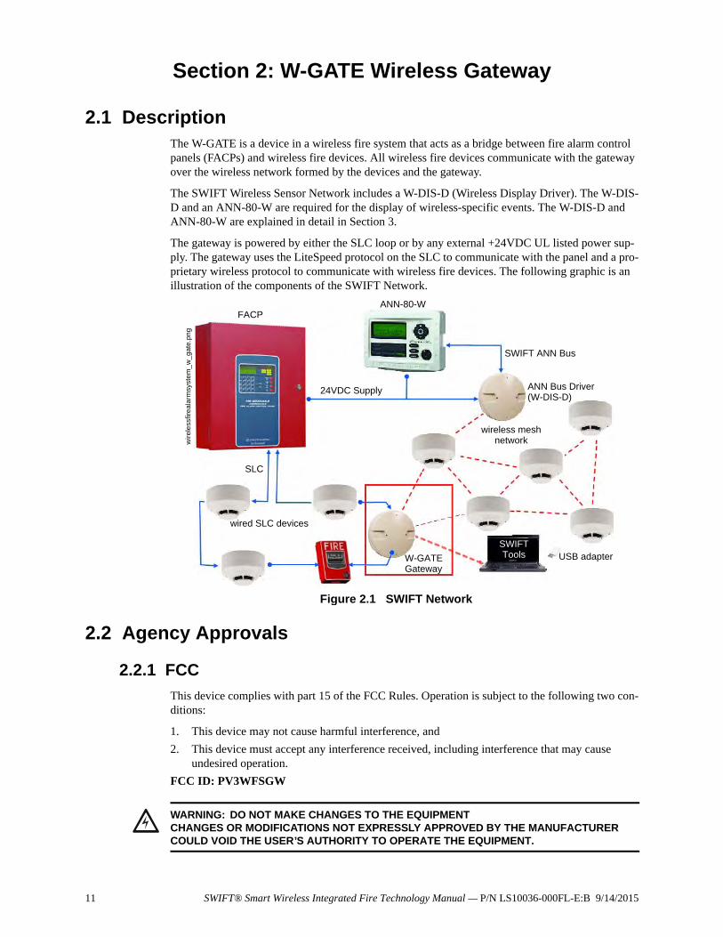
The gateway is powered by either the SLC loop or by any external +24VDC UL listed power sup-ply. The gateway uses the LiteSpeed protocol on the SLC to communicate with the panel and a pro-prietary wireless protocol to communicate with wireless fire devices. The following graphic is an illustration of the components of the SWIFT Network.
2.2 Agency Approvals
2.2.1 FCC
This device complies with part 15 of the FCC Rules. Operation is subject to the following two con-ditions:
1. This device may not cause harmful interference, and
2. This device must accept any interference received, including interference that may cause undesired operation.
FCC ID: PV3WFSGW
Figure 2.1 SWIFT Network
FACPANN-80-W
SLC
wired SLC devices
W-GATEGateway
SWIFT ANN Bus
ANN Bus Driver(W-DIS-D)
wireless mesh network
SWIFTTools
wir
ele
ssfir
eal
arm
syst
em
_w
_gat
e.p
ng
USB adapter
24VDC Supply
!WARNING: DO NOT MAKE CHANGES TO THE EQUIPMENTCHANGES OR MODIFICATIONS NOT EXPRESSLY APPROVED BY THE MANUFACTURER COULD VOID THE USER’S AUTHORITY TO OPERATE THE EQUIPMENT.
12 SWIFT® Smart Wireless Integrated Fire Technology Manual — P/N LS10036-000FL-E:B 9/14/2015
W-GATE Wireless Gateway Specifications
2.2.2 Federal Institute of Telecommunications
This device utilizes the Honeywell915 rev A radio module and complies with IFETEL standard(s).
IFT: RCPHOSW14-1983
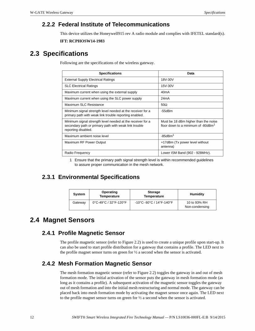
2.3 SpecificationsFollowing are the specifications of the wireless gateway.
2.3.1 Environmental Specifications
2.4 Magnet Sensors
2.4.1 Profile Magnetic Sensor
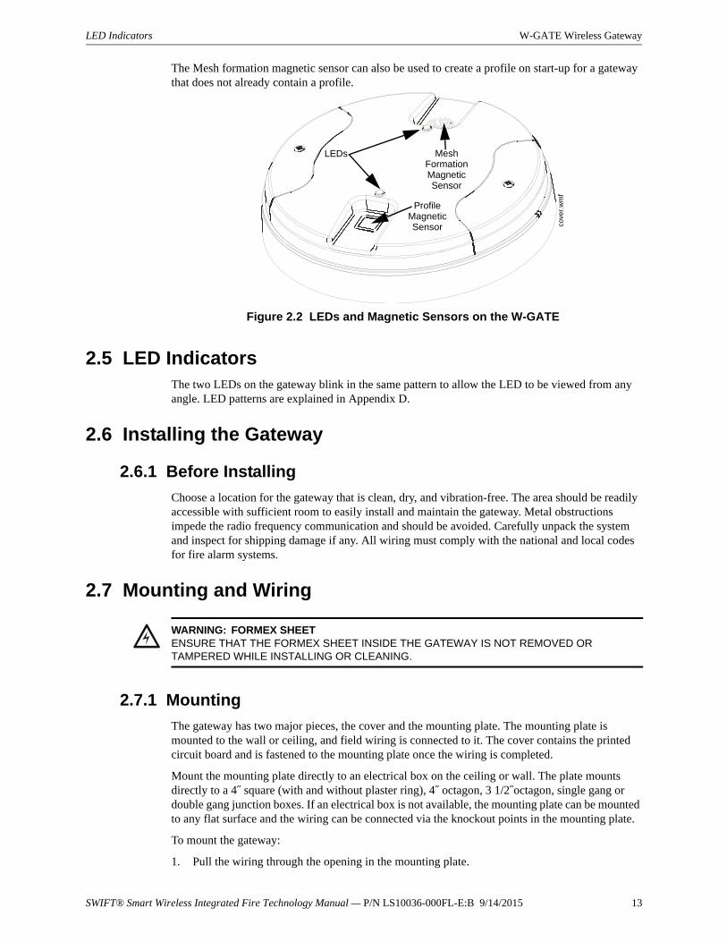
The profile magnetic sensor (refer to Figure 2.2) is used to create a unique profile upon start-up. It can also be used to start profile distribution for a gateway that contains a profile. The LED next to the profile magnet sensor turns on green for ½ a second when the sensor is activated.
2.4.2 Mesh Formation Magnetic Sensor
The mesh formation magnetic sensor (refer to Figure 2.2) toggles the gateway in and out of mesh formation mode. The initial activation of the sensor puts the gateway in mesh formation mode (as long as it contains a profile). A subsequent activation of the magnetic sensor toggles the gateway out of mesh formation and into the initial mesh restructuring and normal mode. The gateway can be placed back into mesh formation mode by activating the magnet sensor once again. The LED next to the profile magnet sensor turns on green for ½ a second when the sensor is activated.
Specifications Data
External Supply Electrical Ratings 18V-30V
SLC Electrical Ratings 15V-30V
Maximum current when using the external supply 40mA
Maximum current when using the SLC power supply 24mA
Maximum SLC Resistance 50Ω
Minimum signal strength level needed at the receiver for a primary path with weak link trouble reporting enabled.
-55dBm
Minimum signal strength level needed at the receiver for a secondary path or primary path with weak link trouble reporting disabled.
Must be 18 dBm higher than the noise floor down to a minimum of -80dBm1
1 Ensure that the primary path signal strength level is within recommended guidelines to assure proper communication in the mesh network.
Maximum ambient noise level -85dBm1
Maximum RF Power Output +17dBm (Tx power level without antenna)
Radio Frequency Lower ISM Band (902 - 928MHz).
SystemOperating
TemperatureStorage
TemperatureHumidity
Gateway 0°C-49°C / 32°F-120°F -10°C- 60°C / 14°F-140°F 10 to 93% RHNon-condensing
SWIFT® Smart Wireless Integrated Fire Technology Manual — P/N LS10036-000FL-E:B 9/14/2015 13
LED Indicators W-GATE Wireless Gateway
The Mesh formation magnetic sensor can also be used to create a profile on start-up for a gateway that does not already contain a profile.
2.5 LED IndicatorsThe two LEDs on the gateway blink in the same pattern to allow the LED to be viewed from any angle. LED patterns are explained in Appendix D.
2.6 Installing the Gateway
2.6.1 Before Installing
Choose a location for the gateway that is clean, dry, and vibration-free. The area should be readily accessible with sufficient room to easily install and maintain the gateway. Metal obstructions impede the radio frequency communication and should be avoided. Carefully unpack the system and inspect for shipping damage if any. All wiring must comply with the national and local codes for fire alarm systems.
2.7 Mounting and Wiring
2.7.1 Mounting
The gateway has two major pieces, the cover and the mounting plate. The mounting plate is mounted to the wall or ceiling, and field wiring is connected to it. The cover contains the printed circuit board and is fastened to the mounting plate once the wiring is completed.
Mount the mounting plate directly to an electrical box on the ceiling or wall. The plate mounts directly to a 4˝ square (with and without plaster ring), 4˝ octagon, 3 1/2˝octagon, single gang or double gang junction boxes. If an electrical box is not available, the mounting plate can be mounted to any flat surface and the wiring can be connected via the knockout points in the mounting plate.
To mount the gateway:
1. Pull the wiring through the opening in the mounting plate.
Figure 2.2 LEDs and Magnetic Sensors on the W-GATE
LEDs Mesh Formation Magnetic Sensor
Profile Magnetic Sensor co
ver.
wm
f
!WARNING: FORMEX SHEETENSURE THAT THE FORMEX SHEET INSIDE THE GATEWAY IS NOT REMOVED OR TAMPERED WHILE INSTALLING OR CLEANING.
14 SWIFT® Smart Wireless Integrated Fire Technology Manual — P/N LS10036-000FL-E:B 9/14/2015
W-GATE Wireless Gateway Mounting and Wiring
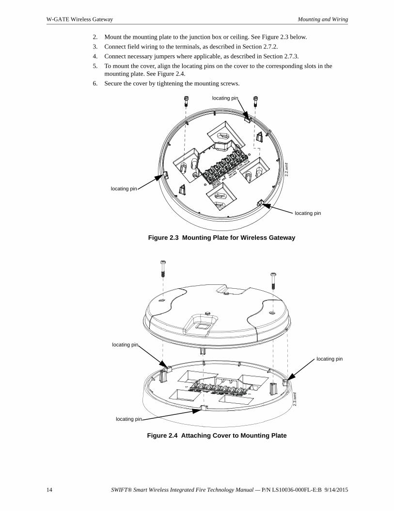
2. Mount the mounting plate to the junction box or ceiling. See Figure 2.3 below.
3. Connect field wiring to the terminals, as described in Section 2.7.2.
4. Connect necessary jumpers where applicable, as described in Section 2.7.3.
5. To mount the cover, align the locating pins on the cover to the corresponding slots in the mounting plate. See Figure 2.4.
6. Secure the cover by tightening the mounting screws.
Figure 2.3 Mounting Plate for Wireless Gateway
2.2
.wm
f
locating pin
locating pin
locating pin
Figure 2.4 Attaching Cover to Mounting Plate
2.3
.wm
f
locating pin
locating pin
locating pin
SWIFT® Smart Wireless Integrated Fire Technology Manual — P/N LS10036-000FL-E:B 9/14/2015 15
Mounting and Wiring W-GATE Wireless Gateway
2.7.2 Wiring• All wiring must be installed in compliance with the National Electrical Code and the local
codes having jurisdiction.
• 12-18 AWG is recommended.
For wiring connections:
1. Strip about 3/8” of insulation from the end of the wire.
2. Slide the stripped end of the wire under the appropriate terminal and tighten the screw.
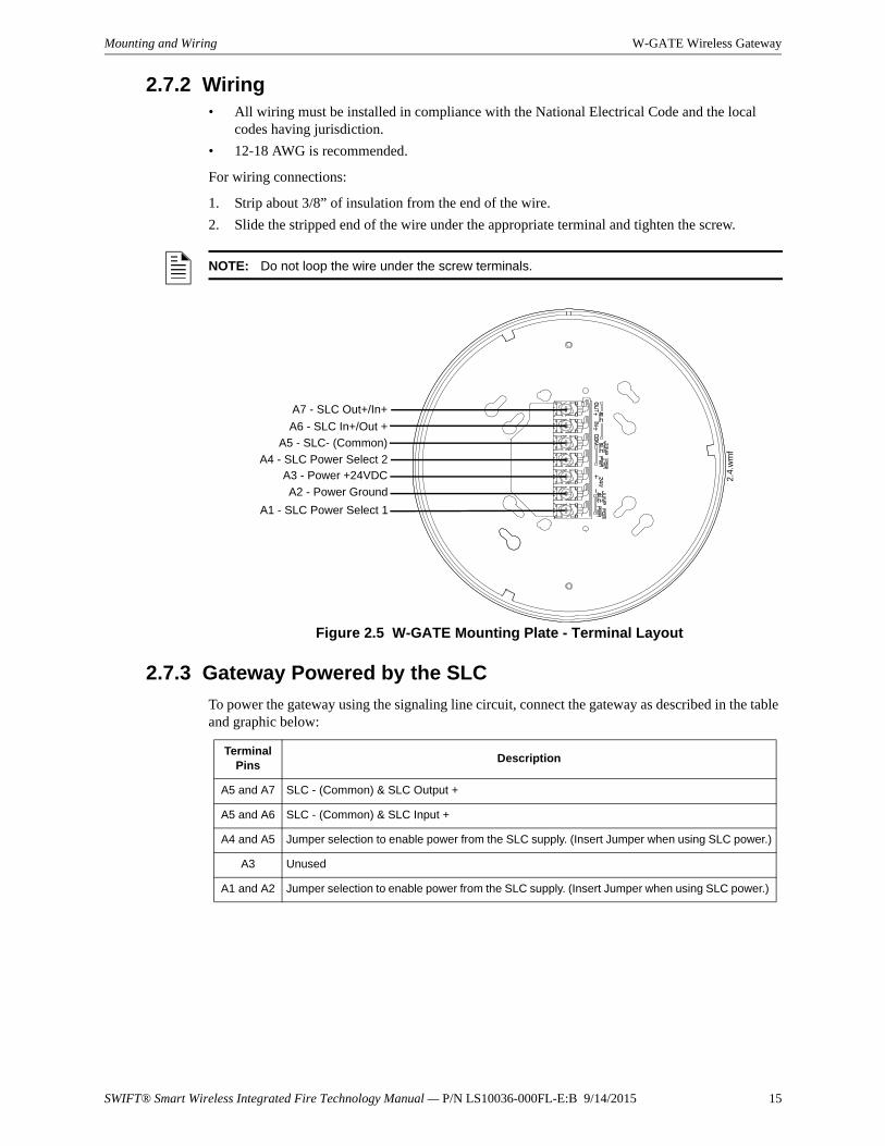
2.7.3 Gateway Powered by the SLC
To power the gateway using the signaling line circuit, connect the gateway as described in the table and graphic below:
NOTE: Do not loop the wire under the screw terminals.
Figure 2.5 W-GATE Mounting Plate - Terminal Layout
A7 - SLC Out+/In+
A6 - SLC In+/Out +
A5 - SLC- (Common)
A4 - SLC Power Select 2A3 - Power +24VDC
A2 - Power Ground
A1 - SLC Power Select 1
2.4
.wm
f
Terminal Pins
Description
A5 and A7 SLC - (Common) & SLC Output +
A5 and A6 SLC - (Common) & SLC Input +
A4 and A5 Jumper selection to enable power from the SLC supply. (Insert Jumper when using SLC power.)
A3 Unused
A1 and A2 Jumper selection to enable power from the SLC supply. (Insert Jumper when using SLC power.)

16 SWIFT® Smart Wireless Integrated Fire Technology Manual — P/N LS10036-000FL-E:B 9/14/2015
W-GATE Wireless Gateway Mounting and Wiring
The gateway provides isolation of short circuits on the SLC in Class A (Style 6) installations. SLC connections are power-limited by the panel. An interruption in the SLC that causes a loss of power at the gateway for more than 100ms may result in a trouble condition and loss of fire protection provided by the wireless devices for approximately 15 minutes. Use of an external +24V power source (not SLC power) is recommended for installations that require fire protection in the pres-ence of short circuits, including Class A applications and applications that use isolator modules. Refer to the SLC Wiring Manual for more information on wiring using isolators.
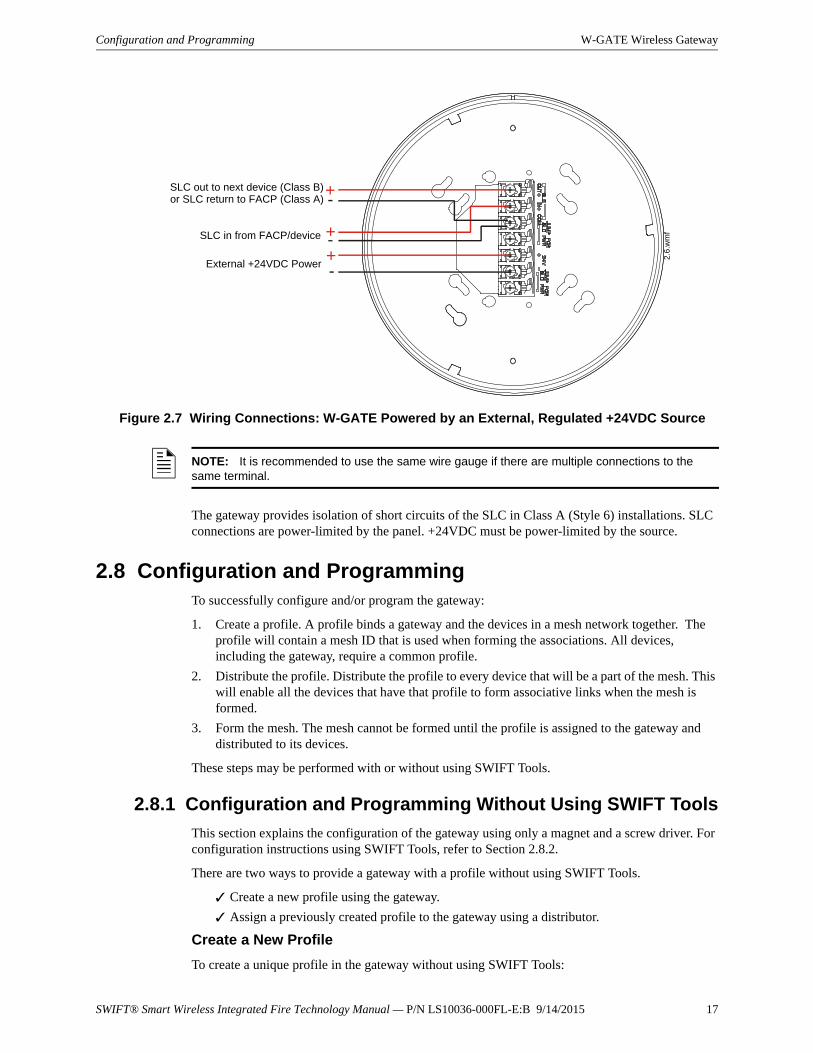
2.7.4 Gateway Powered by an External, Regulated +24VDC Source
To power the gateway using an external, regulated +24VDC source, connect the gateway as described in the table and drawing below.
+
+
-
-
Figure 2.6 Wiring Connections: W-GATE Powered by the SLC
SLC out to next device (Class B)or SLC return to FACP (Class A)
SLC in from FACP/device
jumpers
2.5
.wm
f
NOTE: Use of the same wire gauge is recommended if there are multiple connections to the same terminal.
Terminal Pins Devices Powered
A5 & A7 SLC Output
A5 & A6 SLC Input
A4 Unused
A2 & A3 +24VDC input. Voltage range from +18VDC to +30VDC.Use only power-limited device circuits.
A1 Unused
SWIFT® Smart Wireless Integrated Fire Technology Manual — P/N LS10036-000FL-E:B 9/14/2015 17
Configuration and Programming W-GATE Wireless Gateway
The gateway provides isolation of short circuits of the SLC in Class A (Style 6) installations. SLC connections are power-limited by the panel. +24VDC must be power-limited by the source.
2.8 Configuration and ProgrammingTo successfully configure and/or program the gateway:
1. Create a profile. A profile binds a gateway and the devices in a mesh network together. The profile will contain a mesh ID that is used when forming the associations. All devices, including the gateway, require a common profile.
2. Distribute the profile. Distribute the profile to every device that will be a part of the mesh. This will enable all the devices that have that profile to form associative links when the mesh is formed.
3. Form the mesh. The mesh cannot be formed until the profile is assigned to the gateway and distributed to its devices.
These steps may be performed with or without using SWIFT Tools.
2.8.1 Configuration and Programming Without Using SWIFT Tools
This section explains the configuration of the gateway using only a magnet and a screw driver. For configuration instructions using SWIFT Tools, refer to Section 2.8.2.
There are two ways to provide a gateway with a profile without using SWIFT Tools.
Create a new profile using the gateway.
Assign a previously created profile to the gateway using a distributor.
Create a New Profile
To create a unique profile in the gateway without using SWIFT Tools:
+
+
-
-+-
Figure 2.7 Wiring Connections: W-GATE Powered by an External, Regulated +24VDC Source
SLC in from FACP/device
External +24VDC Power
SLC out to next device (Class B)or SLC return to FACP (Class A)
2.6
.wm
f
NOTE: It is recommended to use the same wire gauge if there are multiple connections to the same terminal.
18 SWIFT® Smart Wireless Integrated Fire Technology Manual — P/N LS10036-000FL-E:B 9/14/2015
W-GATE Wireless Gateway Configuration and Programming
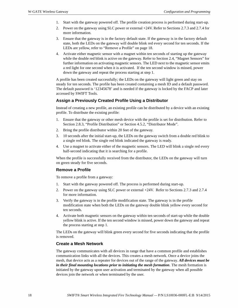
1. Start with the gateway powered off. The profile creation process is performed during start-up.
2. Power on the gateway using SLC power or external +24V. Refer to Sections 2.7.3 and 2.7.4 for more information.
3. Ensure that the gateway is in the factory default state. If the gateway is in the factory default state, both the LEDs on the gateway will double blink red every second for ten seconds. If the LEDs are yellow, refer to “Remove a Profile” on page 18.
4. Activate either magnetic sensor with a magnet within ten seconds of starting up the gateway while the double red blink is active on the gateway. Refer to Section 2.4, “Magnet Sensors” for further information on activating magnetic sensors. The LED next to the magnetic sensor emits a red light for one second when it is activated. If the ten second window is missed, power down the gateway and repeat the process starting at step 1.
A profile has been created successfully; the LEDs on the gateway will light green and stay on steady for ten seconds. The profile has been created containing a mesh ID and a default password. The default password is ‘12345678’ and is needed if the gateway is locked by the FACP and later accessed by SWIFT Tools.
Assign a Previously Created Profile Using a Distributor
Instead of creating a new profile, an existing profile can be distributed by a device with an existing profile. To distribute the existing profile:
1. Ensure that the gateway or other mesh device with the profile is set for distribution. Refer to Section 2.8.3, “Profile Distribution” or Section 4.5.2, “Distributor Mode”.
2. Bring the profile distributor within 20 feet of the gateway.
3. 10 seconds after the initial start-up, the LEDs on the gateway switch from a double red blink to a single red blink. The single red blink indicated the gateway is ready.
4. Use a magnet to activate either of the magnetic sensors. The LED will blink a single red every half-second indicating that it is searching for a profile.
When the profile is successfully received from the distributor, the LEDs on the gateway will turn on green steady for five seconds.
Remove a Profile
To remove a profile from a gateway:
1. Start with the gateway powered off. The process is performed during start-up.
2. Power on the gateway using SLC power or external +24V. Refer to Sections 2.7.3 and 2.7.4 for more information.
3. Verify the gateway is in the profile modification state. The gateway is in the profile modification state when both the LEDs on the gateway double blink yellow every second for ten seconds.
4. Activate both magnetic sensors on the gateway within ten seconds of start-up while the double yellow blink is active. If the ten second window is missed, power down the gateway and repeat the process starting at step 1.
The LEDs on the gateway will blink green every second for five seconds indicating that the profile is removed.
Create a Mesh Network
The gateway communicates with all devices in range that have a common profile and establishes communication links with all the devices. This creates a mesh network. Once a device joins the mesh, that device acts as a repeater for devices out of the range of the gateway. All devices must be in their final mounting locations prior to initiating the mesh formation. The mesh formation is initiated by the gateway upon user activation and terminated by the gateway when all possible devices join the network or when terminated by the user.
SWIFT® Smart Wireless Integrated Fire Technology Manual — P/N LS10036-000FL-E:B 9/14/2015 19
Configuration and Programming W-GATE Wireless Gateway
To form a mesh network, ensure that the gateway is powered on and contains a profile. (Refer to Section 2.5 on page 13 for information on how the gateway indicates its status). Activate the “Mesh Formation” magnet sensor on the gateway. Refer to Figure 2.2 for sensor location.
The gateway will then transition to the mesh formation mode and establish communication with all the devices containing a common profile. The blink pattern on the gateway indicates that it is in mesh formation mode. At this stage, both the LEDs on the gateway will blink twice every 7 sec-onds.
• The first blink is green and the second blink is red when the gateway is acting as a profile distributor and forming the mesh.
• The first blink is green and the second blink is yellow when the gateway is only forming the mesh.
Mesh formation typically takes one minute for each device in the mesh. Mesh formation automati-cally terminates 10 minutes after the last device joins the mesh. Mesh formation can be terminated manually by the user by again activating the mesh formation magnetic sensor.
Once the mesh formation is complete, the network automatically transitions to restructure the mesh. For operating instructions, refer to Section 2.9, “Operations”.
2.8.2 Configuration and Programming Using SWIFT Tools
Assign a Profile
To assign a profile to the gateway using SWIFT Tools:
1. Connect the W-USB dongle device to your laptop. For more information on the USB dongle, refer to Section 5, “USB Adapter”, on page 54.
2. Launch SWIFT Tools. Refer to Appendix A for more information.
3. From the Home Screen, select the Create Mesh Network function.
4. Create a new profile or Import an existing profile as required.
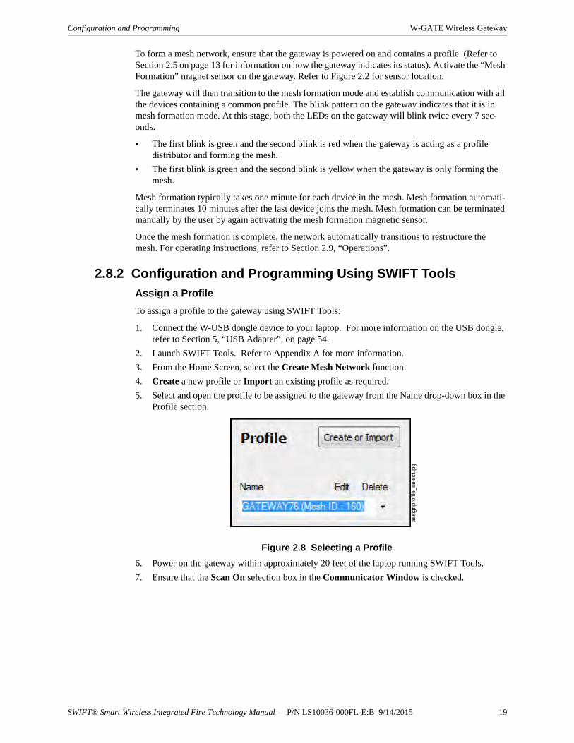
5. Select and open the profile to be assigned to the gateway from the Name drop-down box in the Profile section.
6. Power on the gateway within approximately 20 feet of the laptop running SWIFT Tools.
7. Ensure that the Scan On selection box in the Communicator Window is checked.
Figure 2.8 Selecting a Profile
ass
ign
pro
file_
sele
ct.jp
g
20 SWIFT® Smart Wireless Integrated Fire Technology Manual — P/N LS10036-000FL-E:B 9/14/2015
W-GATE Wireless Gateway Configuration and Programming
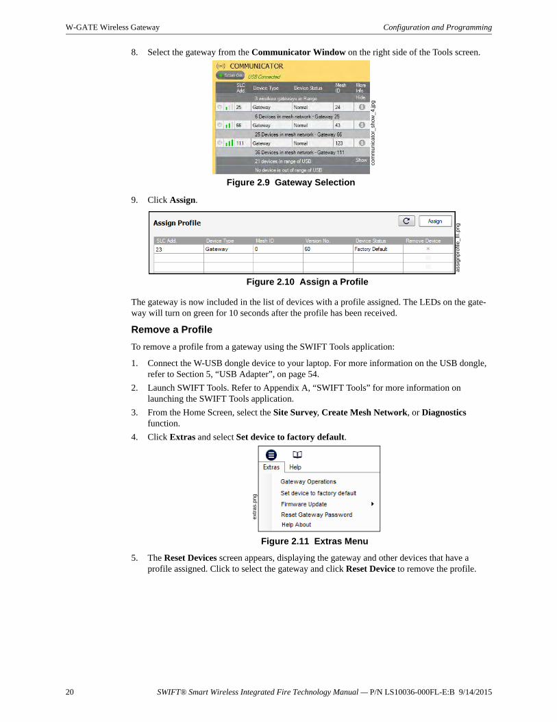
8. Select the gateway from the Communicator Window on the right side of the Tools screen.
9. Click Assign.
The gateway is now included in the list of devices with a profile assigned. The LEDs on the gate-way will turn on green for 10 seconds after the profile has been received.
Remove a Profile
To remove a profile from a gateway using the SWIFT Tools application:
1. Connect the W-USB dongle device to your laptop. For more information on the USB dongle, refer to Section 5, “USB Adapter”, on page 54.
2. Launch SWIFT Tools. Refer to Appendix A, “SWIFT Tools” for more information on launching the SWIFT Tools application.
3. From the Home Screen, select the Site Survey, Create Mesh Network, or Diagnostics function.
4. Click Extras and select Set device to factory default.
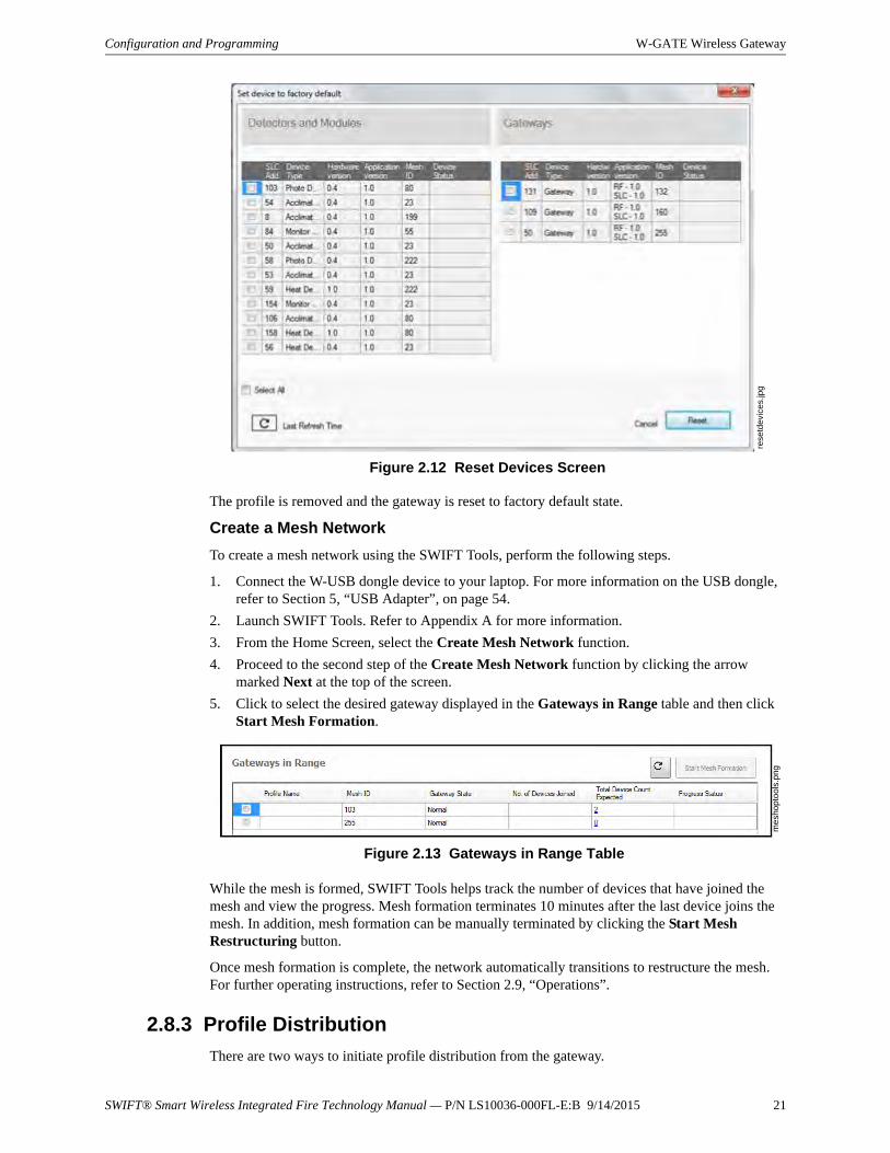
5. The Reset Devices screen appears, displaying the gateway and other devices that have a profile assigned. Click to select the gateway and click Reset Device to remove the profile.
Figure 2.9 Gateway Selection
com
mun
ica
tor_
show
_4,
jpg
assi
gnpr
ofile
_III
.png
Figure 2.10 Assign a Profile
extr
as.
png
Figure 2.11 Extras Menu
SWIFT® Smart Wireless Integrated Fire Technology Manual — P/N LS10036-000FL-E:B 9/14/2015 21
Configuration and Programming W-GATE Wireless Gateway
The profile is removed and the gateway is reset to factory default state.
Create a Mesh Network
To create a mesh network using the SWIFT Tools, perform the following steps.
1. Connect the W-USB dongle device to your laptop. For more information on the USB dongle, refer to Section 5, “USB Adapter”, on page 54.
2. Launch SWIFT Tools. Refer to Appendix A for more information.
3. From the Home Screen, select the Create Mesh Network function.
4. Proceed to the second step of the Create Mesh Network function by clicking the arrow marked Next at the top of the screen.
5. Click to select the desired gateway displayed in the Gateways in Range table and then click Start Mesh Formation.
While the mesh is formed, SWIFT Tools helps track the number of devices that have joined the mesh and view the progress. Mesh formation terminates 10 minutes after the last device joins the mesh. In addition, mesh formation can be manually terminated by clicking the Start Mesh Restructuring button.
Once mesh formation is complete, the network automatically transitions to restructure the mesh. For further operating instructions, refer to Section 2.9, “Operations”.
2.8.3 Profile Distribution
There are two ways to initiate profile distribution from the gateway.
rese
tdev
ices
.jpg
Figure 2.12 Reset Devices Screen
mes
hopt
ools
.png
Figure 2.13 Gateways in Range Table
22 SWIFT® Smart Wireless Integrated Fire Technology Manual — P/N LS10036-000FL-E:B 9/14/2015
W-GATE Wireless Gateway Configuration and Programming
• Automatically after creating a profile if the profile was not created by SWIFT Tools
• Activating the profile-creating magnetic sensor when the gateway has a profile.
After Creating a Profile
Profile distribution is automatically enabled from the gateway after creating a profile using either magnetic sensor upon the gateway’s start-up. The profile distribution automatically terminates after 10 minutes.
Activating the Profile Magnetic Sensor
Activating the profile magnetic sensor (refer to Figure 2.2) when the gateway has a profile will put the gateway in a mode of distributing the profile to any device that requests a profile. The gate-way’s LED pattern will be altered when it is distributing a profile for easy identification. Profile distribution will automatically terminate after 10 minutes. For more information on gateway LED patterns, refer to Section 2.5 on page 13.
2.8.4 SLC Configuration
The gateway:
communicates with the control panel via the SLC.
is a LiteSpeed-only device.
does not support CLIP mode.
requires the use of an ANN-80-W for event details because FACPs have limited support for displaying all troubles from the wireless device. Refer to the appropriate section below for configuration steps.
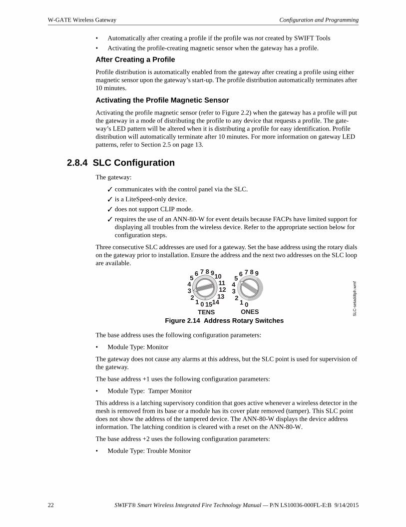
Three consecutive SLC addresses are used for a gateway. Set the base address using the rotary dials on the gateway prior to installation. Ensure the address and the next two addresses on the SLC loop are available.
The base address uses the following configuration parameters:
• Module Type: Monitor
The gateway does not cause any alarms at this address, but the SLC point is used for supervision of the gateway.
The base address +1 uses the following configuration parameters:
• Module Type: Tamper Monitor
This address is a latching supervisory condition that goes active whenever a wireless detector in the mesh is removed from its base or a module has its cover plate removed (tamper). This SLC point does not show the address of the tampered device. The ANN-80-W displays the device address information. The latching condition is cleared with a reset on the ANN-80-W.
The base address +2 uses the following configuration parameters:
• Module Type: Trouble Monitor
TENS
8 910111213
1415012
345
6 7
ONES
8 9
012
345
6 7
Figure 2.14 Address Rotary Switches
SLC
-set
add
tph.
wm
f
SWIFT® Smart Wireless Integrated Fire Technology Manual — P/N LS10036-000FL-E:B 9/14/2015 23
Operations W-GATE Wireless Gateway
This address is a latching or non-latching trouble condition, depending on the trouble event, that goes active whenever a wireless device in the mesh is in a trouble condition. Refer to Section 3.10.3, “Event Messages”, on page 42 for the message displayed at the ANN-80-W for the trouble event. Latching troubles are cleared with a reset on the ANN-80-W.
The specific address and trouble condition is displayed on the ANN-80-W.
2.9 Operations
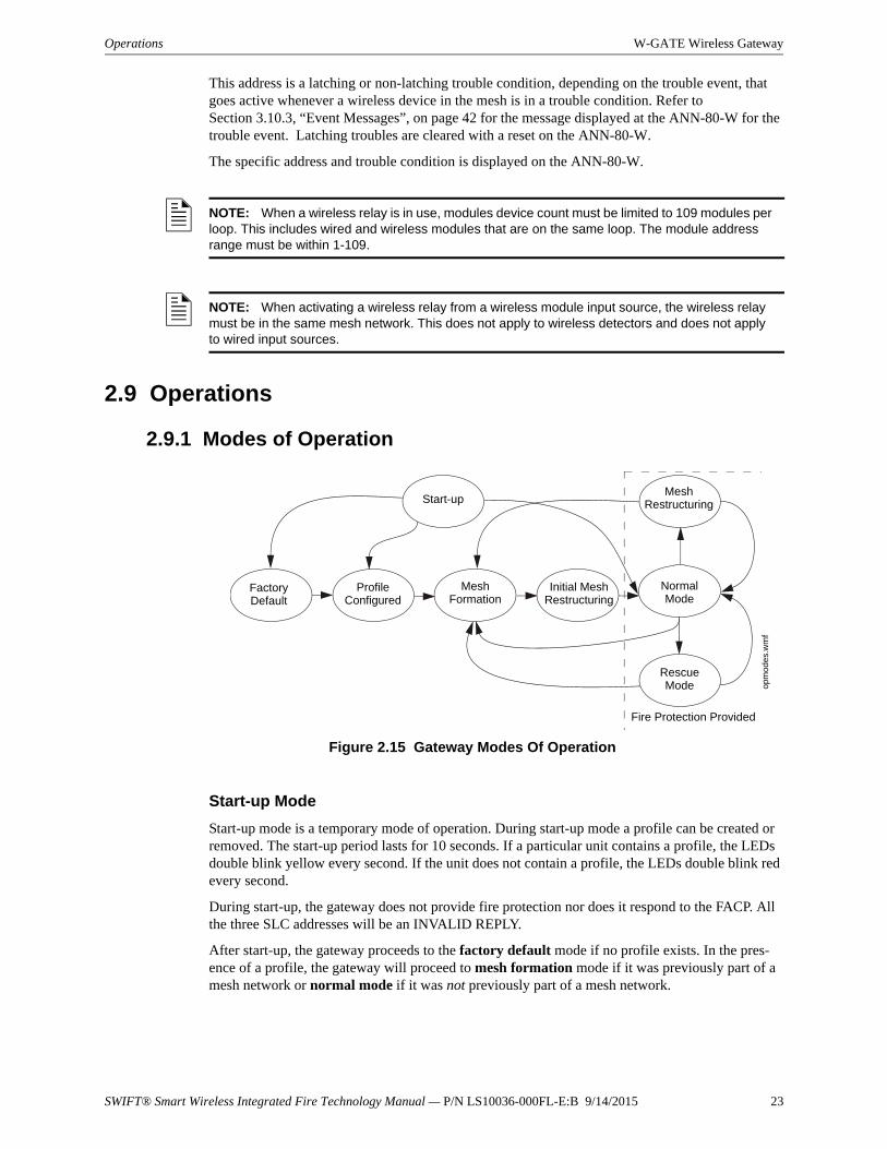
2.9.1 Modes of Operation
Start-up Mode
Start-up mode is a temporary mode of operation. During start-up mode a profile can be created or removed. The start-up period lasts for 10 seconds. If a particular unit contains a profile, the LEDs double blink yellow every second. If the unit does not contain a profile, the LEDs double blink red every second.
During start-up, the gateway does not provide fire protection nor does it respond to the FACP. All the three SLC addresses will be an INVALID REPLY.
After start-up, the gateway proceeds to the factory default mode if no profile exists. In the pres-ence of a profile, the gateway will proceed to mesh formation mode if it was previously part of a mesh network or normal mode if it was not previously part of a mesh network.
NOTE: When a wireless relay is in use, modules device count must be limited to 109 modules per loop. This includes wired and wireless modules that are on the same loop. The module address range must be within 1-109.
NOTE: When activating a wireless relay from a wireless module input source, the wireless relay must be in the same mesh network. This does not apply to wireless detectors and does not apply to wired input sources.
Figure 2.15 Gateway Modes Of Operationo
pm
ode
s.w
mf
Start-up
Factory Default
Profile Configured
Mesh Formation
Initial Mesh Restructuring
Normal Mode
Mesh Restructuring
Rescue Mode
Fire Protection Provided
24 SWIFT® Smart Wireless Integrated Fire Technology Manual — P/N LS10036-000FL-E:B 9/14/2015
W-GATE Wireless Gateway Operations
Factory Default Mode
Factory default mode is the initial mode of the gateway. In this mode, the gateway and peripheral devices do not provide any fire protection. The gateway does not communicate with wireless detec-tors or modules in factory default mode. The only wireless communication in factory default mode is between the gateway and SWIFT Tools. SWIFT Tools must be within 20 feet of the gateway for proper communication. The gateway must be assigned a profile before continuing configuration.
The gateway reports “Factory Default” to the communicator display of SWIFT Tools.
The gateway’s base address will be normal and the supervisory point (base address + 1) will also be normal. The trouble point (base address + 2) will indicate an open circuit.
Profile Configured
The gateway enters the profile configured mode once a profile is assigned by SWIFT Tools or a distributor; or after creating a profile using the magnetic sensor. Profile configured mode is a tem-porary mode before the gateway transitions to mesh formation or normal mode.
Mesh Formation
The gateway must have a profile before entering mesh formation mode. The gateway and the peripheral devices do not provide any fire protection in this mode. The gateway enters mesh forma-tion mode:
after creating a profile using the mesh formation sensor.
after activating the mesh formation sensor with a magnet when the gateway contains a profile.
automatically after start-up when the gateway was previously part of a mesh.
by a command from the SWIFT Tools application.
A gateway in mesh formation mode instructs all devices in the mesh to also transition to mesh for-mation mode. The gateway and all communicating devices search for new or lost devices with the same profile to join the network.
If the gateway automatically entered mesh formation after start-up, mesh formation will terminate 10 minutes after the last device has joined or after all existing devices are recovered. If new devices are found or if mesh formation was initiated by the user, then mesh formation terminates after a period of 10 minutes without any new devices joining the mesh. At any point Mesh forma-tion can be terminated by user interaction by activating the magnet sensor again or by using the SWIFT Tools application.
The gateway reports “Mesh Formation” to the communicator display of the SWIFT Tools applica-tion.
The gateway’s base address will be normal and the supervisory point (base address + 1) will also be normal. The trouble point (base address + 2) will indicate an open circuit.
Initial Mesh Restructuring Mode
Initial mesh restructuring mode automatically runs after each mesh formation. The gateway and peripheral devices do not provide fire protection during the initial mesh restructuring mode. Mesh restructuring analyzes signal strengths between devices. The gateway designates the primary and secondary communication paths between devices that provide a redundant path for all transmis-sions. Mesh restructuring automatically terminates once all devices have a redundant communica-tion path and signal strengths that meet the requirements of primary and secondary transmission paths. Any device that does not have a redundant path or meet the requirements for signal strength will report a fault.
The gateway reports “Restructuring” to the communicator display of the SWIFT Tools application.
The gateway’s base address will be normal and the supervisory point (base address + 1) will also be normal. The trouble point (base address + 2) will indicate an open circuit.
SWIFT® Smart Wireless Integrated Fire Technology Manual — P/N LS10036-000FL-E:B 9/14/2015 25
Operations W-GATE Wireless Gateway
Normal Mode
Normal mode is the network’s standard operating state. The mesh network has been formed and is providing fire protection. The mesh network will continuously search for additional devices with a matching profile to join the mesh. To avoid interference, the mesh network periodically checks for adjacent mesh networks created by Honeywell. The gateway reports “Normal” to the communica-tor display of the SWIFT Tools application.
Rescue Mode
During normal mode, if an out-of-network device with a matching profile is discovered by the net-work, the gateway will trigger rescue mode in all communicating devices. All devices in communi-cation continue to provide fire protection during rescue mode but also search for a lost or added device. Rescue mode automatically terminates 3 minutes after the last device is rescued and returns to normal mode. The gateway does not report troubles during rescue mode but reports “Rescue” to the communicator display of the SWIFT Tools application.
Mesh Restructuring Mode
In addition to the initial mesh restructuring mode, mesh restructuring is automatically performed after any restoration of communication to a device or to recover from a link failure (Class A fault). Mesh restructuring that occurs during normal mode does not generate a trouble message. During mesh restructuring, fire protection is provided by all devices that are participating in the mesh com-munication. The gateway reports “Restructuring” to the communicator display of the SWIFT Tools application.
Bootloader Mode
The gateway enters the bootloader mode when its firmware is being updated using SWIFT Tools. The gateway does not communicate with the FACP during bootloader mode. The gateway reports “Bootloader” to the communicator display of the SWIFT Tools application.
2.9.2 LED Patterns
The LED indicator patterns are provided in Appendix D on page 71.
2.9.3 Lock/Unlock the Gateway
The gateway can be locked to prevent access to the magnetic sensors and to password-protect all wireless interactions. The lock function can be performed by SWIFT Tools. When SWIFT Tools is used to lock the gateway, a password must be provided for all future interactions, including unlock-ing the gateway. If the gateway was previously locked with a password from SWIFT Tools, the pre-vious password will be applied. Use this password for all future interactions with the SWIFT Tools application.
Lock/Unlock the Gateway Using SWIFT Tools
To lock/unlock the gateway:
1. Connect the W-USB dongle device to your computer. For more information on USB dongle, refer to Section 5.
2. Launch the SWIFT Tools application. Refer to Appendix A, “SWIFT Tools” for more information.
3. From the Home Screen, select the Site Survey, Create Mesh Network, or Diagnostics function.
26 SWIFT® Smart Wireless Integrated Fire Technology Manual — P/N LS10036-000FL-E:B 9/14/2015
W-GATE Wireless Gateway Operations
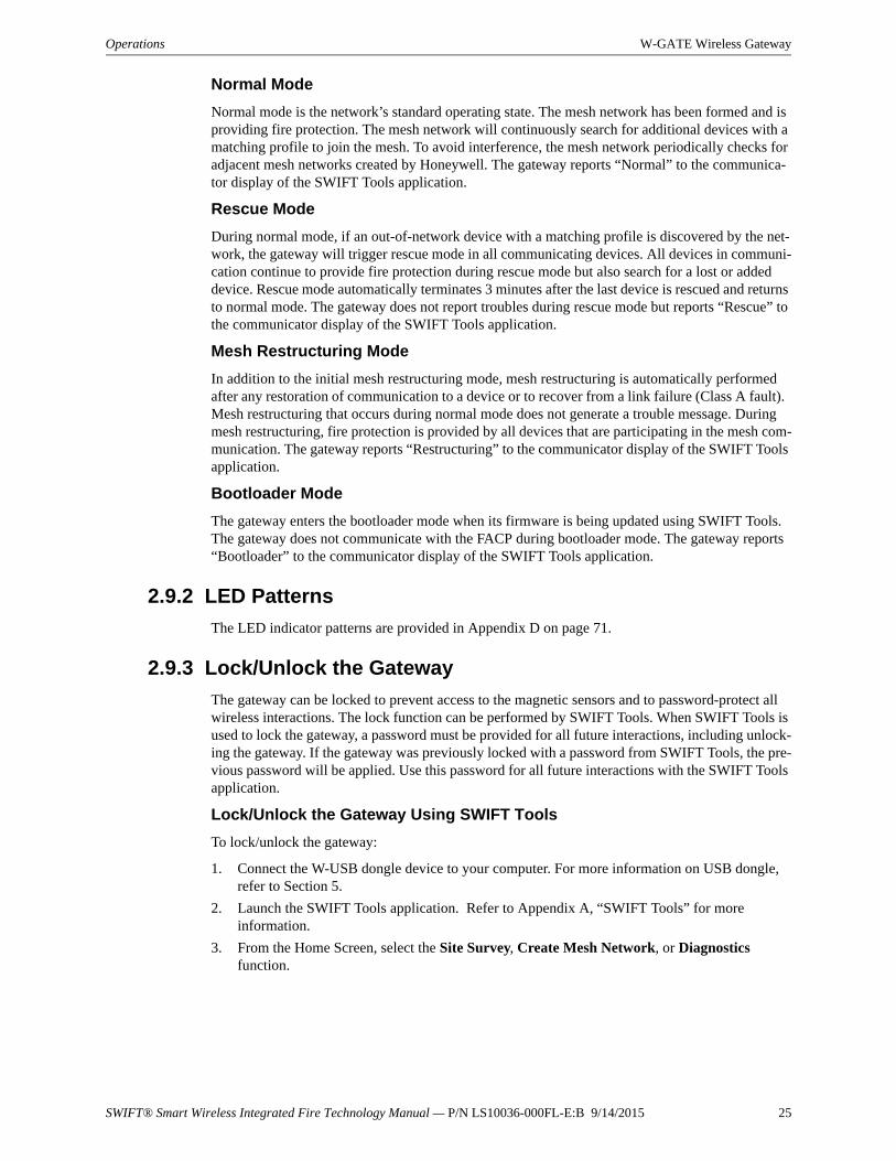
4. Click Extras. The following screen is displayed.
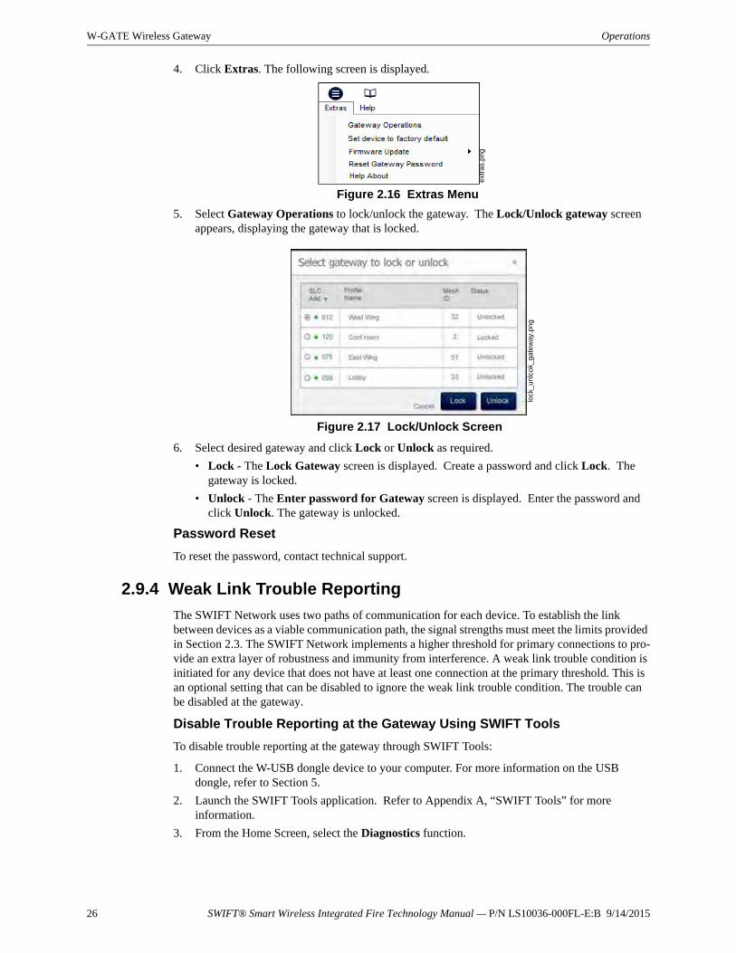
5. Select Gateway Operations to lock/unlock the gateway. The Lock/Unlock gateway screen appears, displaying the gateway that is locked.
6. Select desired gateway and click Lock or Unlock as required.
• Lock - The Lock Gateway screen is displayed. Create a password and click Lock. The gateway is locked.
• Unlock - The Enter password for Gateway screen is displayed. Enter the password and click Unlock. The gateway is unlocked.
Password Reset
To reset the password, contact technical support.
2.9.4 Weak Link Trouble Reporting
The SWIFT Network uses two paths of communication for each device. To establish the link between devices as a viable communication path, the signal strengths must meet the limits provided in Section 2.3. The SWIFT Network implements a higher threshold for primary connections to pro-vide an extra layer of robustness and immunity from interference. A weak link trouble condition is initiated for any device that does not have at least one connection at the primary threshold. This is an optional setting that can be disabled to ignore the weak link trouble condition. The trouble can be disabled at the gateway.
Disable Trouble Reporting at the Gateway Using SWIFT Tools
To disable trouble reporting at the gateway through SWIFT Tools:
1. Connect the W-USB dongle device to your computer. For more information on the USB dongle, refer to Section 5.
2. Launch the SWIFT Tools application. Refer to Appendix A, “SWIFT Tools” for more information.
3. From the Home Screen, select the Diagnostics function.
extr
as.
png
Figure 2.16 Extras Menu
lock
_un
lco
k_g
ate
way
.png
Figure 2.17 Lock/Unlock Screen
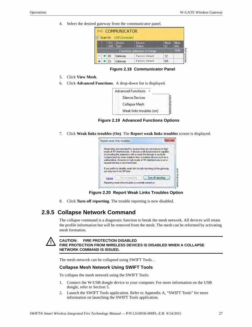
SWIFT® Smart Wireless Integrated Fire Technology Manual — P/N LS10036-000FL-E:B 9/14/2015 27
Operations W-GATE Wireless Gateway
4. Select the desired gateway from the communicator panel.
5. Click View Mesh.
6. Click Advanced Functions. A drop-down list is displayed.
7. Click Weak links troubles (On). The Report weak links troubles screen is displayed.
8. Click Turn off reporting. The trouble reporting is now disabled.
2.9.5 Collapse Network CommandThe collapse command is a diagnostic function to break the mesh network. All devices will retain the profile information but will be removed from the mesh. The mesh can be reformed by activating mesh formation.
The mesh network can be collapsed using SWIFT Tools. .
Collapse Mesh Network Using SWIFT Tools
To collapse the mesh network using the SWIFT Tools:
1. Connect the W-USB dongle device to your computer. For more information on the USB dongle, refer to Section 5.
2. Launch the SWIFT Tools application. Refer to Appendix A, “SWIFT Tools” for more information on launching the SWIFT Tools application.
Figure 2.18 Communicator Panel
selc
omm
.pn
g
advf
uncd
rop.
wm
f
Figure 2.19 Advanced Functions Options
advf
uncd
rop.
wm
f
Figure 2.20 Report Weak Links Troubles Option
! CAUTION: FIRE PROTECTION DISABLEDFIRE PROTECTION FROM WIRELESS DEVICES IS DISABLED WHEN A COLLAPSE NETWORK COMMAND IS ISSUED.
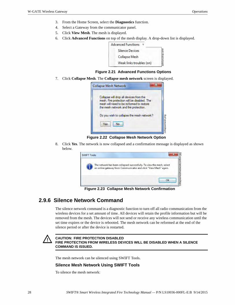
28 SWIFT® Smart Wireless Integrated Fire Technology Manual — P/N LS10036-000FL-E:B 9/14/2015
W-GATE Wireless Gateway Operations
3. From the Home Screen, select the Diagnostics function.
4. Select a Gateway from the communicator panel.
5. Click View Mesh. The mesh is displayed.
6. Click Advanced Functions on top of the mesh display. A drop-down list is displayed.
7. Click Collapse Mesh. The Collapse mesh network screen is displayed.
8. Click Yes. The network is now collapsed and a confirmation message is displayed as shown below.
2.9.6 Silence Network Command
The silence network command is a diagnostic function to turn off all radio communication from the wireless devices for a set amount of time. All devices will retain the profile information but will be removed from the mesh. The devices will not send or receive any wireless communication until the set time expires or the device is rebooted. The mesh network can be reformed at the end of the silence period or after the device is restarted.
The mesh network can be silenced using SWIFT Tools.
Silence Mesh Network Using SWIFT Tools
To silence the mesh network:
advf
uncd
rop.
wm
f
Figure 2.21 Advanced Functions Options
colla
pse
me
sh.p
ng
Figure 2.22 Collapse Mesh Network Option
colla
pse
mes
hne
twor
kcon
firm
.jpg
Figure 2.23 Collapse Mesh Network Confirmation
! CAUTION: FIRE PROTECTION DISABLEDFIRE PROTECTION FROM WIRELESS DEVICES WILL BE DISABLED WHEN A SILENCE COMMAND IS ISSUED.

SWIFT® Smart Wireless Integrated Fire Technology Manual — P/N LS10036-000FL-E:B 9/14/2015 29
Operations W-GATE Wireless Gateway
1. Connect the W-USB dongle device to your computer. For more information on the USB dongle, refer to Section 5.
2. Launch the SWIFT Tools application. Refer to Appendix A, “SWIFT Tools” for more information.
3. From the Home Screen, select the Diagnostics function.
4. Select a Gateway from the communicator panel.
5. Click View Mesh. The mesh is displayed.
6. Click Advanced Functions on top of the mesh display. A drop-down list is displayed.
7. Click Silence Devices. The Silence mesh network screen is displayed.
8. Select the time interval to silence the wireless devices from the dropdown list and click Yes.
9. Enter the Verification Password in the Gateway Password screen. The network is silenced and confirmation is displayed as shown below.
2.9.7 Multiple Wireless Sensor Network Installation Restrictions
The SWIFT Network technology shares the RF spectrum with other Honeywell Wireless Sensor Network systems. Honeywell has established a limit of 4 overlapping networks to avoid congestion in the RF spectrum. If the 4 network limit is exceeded, a system trouble will be generated by the system that detects 4 or more adjacent networks. To resolve this trouble, the instances of overlap need to be removed. Refer to Appendix C:, "Troubleshooting and Testing" for suggestions on removing overlap between wireless networks. The trouble will be self-restoring up to 36 hours after the condition is resolved. To expedite the trouble resolution, toggle the network that is reporting the trouble in and out of mesh formation mode.
advf
uncd
rop.
wm
f
Figure 2.24 Advanced Functions Options
sile
nce
me
shn
etw
ork.
jpg
Figure 2.25 Silence Mesh Network Screen
sile
nce
me
shco
nfir
m.jp
g
Figure 2.26 Silence Mesh Network Confirmation Message
30 SWIFT® Smart Wireless Integrated Fire Technology Manual — P/N LS10036-000FL-E:B 9/14/2015
W-GATE Wireless Gateway Operations
2.9.8 Avoiding RF Interference
The SWIFT wireless mesh network uses radio frequency hopping spread spectrum technology to communicate in the 900 MHz ISM band (902MHz to 928MHz). Other commercial and industrial products also operate in this band. If two-way radios or other wireless communication devices are used during the installation process, it is recommended that they be kept at least 4 feet away from the Fire•Lite wireless devices or that they operate on a different frequency band to ensure rapid mesh formation.
A properly installed SWIFT wireless mesh network with primary link reporting enabled will be highly immune to RF interference from other wireless products even when they are nearby. The use of the weak link reporting feature is highly recommended. If the system is installed in a controlled environment where other 900 MHz ISM band devices will not be present, the primary link report-ing feature may be disabled to permit greater distances between installed devices if required.
The SWIFT wireless mesh network will be able to automatically detect and avoid certain types of in-band channel interference (often caused by two-way radios) by using an alternate channel set. The system will log detection and avoidance of this kind of interference in the gateway history as “Walkie Talkie Mode” Entry or Exit.
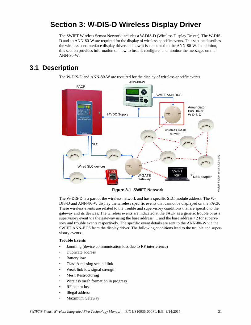
SWIFT® Smart Wireless Integrated Fire Technology Manual — P/N LS10036-000FL-E:B 9/14/2015 31
Section 3: W-DIS-D Wireless Display DriverThe SWIFT Wireless Sensor Network includes a W-DIS-D (Wireless Display Driver). The W-DIS-D and an ANN-80-W are required for the display of wireless-specific events. This section describes the wireless user interface display driver and how it is connected to the ANN-80-W. In addition, this section provides information on how to install, configure, and monitor the messages on the ANN-80-W.
3.1 DescriptionThe W-DIS-D and ANN-80-W are required for the display of wireless-specific events.
The W-DIS-D is a part of the wireless network and has a specific SLC module address. The W-DIS-D and ANN-80-W display the wireless specific events that cannot be displayed on the FACP. These wireless events are related to the trouble and supervisory conditions that are specific to the gateway and its devices. The wireless events are indicated at the FACP as a generic trouble or as a supervisory event via the gateway using the base address +1 and the base address +2 for supervi-sory and trouble events respectively. The specific event details are sent to the ANN-80-W via the SWIFT ANN-BUS from the display driver. The following conditions lead to the trouble and super-visory events.
Trouble Events
• Jamming (device communication loss due to RF interference)
• Duplicate address
• Battery low
• Class A missing second link
• Weak link low signal strength
• Mesh Restructuring
• Wireless mesh formation in progress
• RF comm loss
• Illegal address
• Maximum Gateway
Figure 3.1 SWIFT Network
FACP
24VDC Supply
ANN-80-W
SWIFT ANN-BUS
Annunciator Bus DriverW-DIS-D
SLC
Wired SLC devices
W-GATEGateway
wireless mesh network
SWIFTTools
USB adapter
wir
eles
sfire
alar
msy
stem
_lcd
ui.p
ng
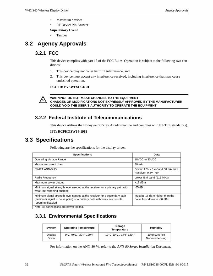
32 SWIFT® Smart Wireless Integrated Fire Technology Manual — P/N LS10036-000FL-E:B 9/14/2015
W-DIS-D Wireless Display Driver Agency Approvals
• Maximum devices
• RF Device No Answer
Supervisory Event
• Tamper
3.2 Agency Approvals
3.2.1 FCC
This device complies with part 15 of the FCC Rules. Operation is subject to the following two con-ditions:
1. This device may not cause harmful interference, and
2. This device must accept any interference received, including interference that may cause undesired operation.
FCC ID: PV3WFSLCDUI
3.2.2 Federal Institute of Telecommunications
This device utilizes the Honeywell915 rev A radio module and complies with IFETEL standard(s).
IFT: RCPHOSW14-1983
3.3 SpecificationsFollowing are the specifications for the display driver.
3.3.1 Environmental Specifications
For information on the ANN-80-W, refer to the ANN-80 Series Installation Document.
!WARNING: DO NOT MAKE CHANGES TO THE EQUIPMENTCHANGES OR MODIFICATIONS NOT EXPRESSLY APPROVED BY THE MANUFACTURER COULD VOID THE USER’S AUTHORITY TO OPERATE THE EQUIPMENT.
Specifications Data
Operating Voltage Range 18VDC to 30VDC
Maximum current draw 30 mA
SWIFT ANN-BUS Driver: 1.5V - 3.4V and 60 mA max.Receiver: 0.2V - 6V
Radio Frequency Lower ISM band (915 MHz)
Maximum power output +17 dBm
Minimum signal strength level needed at the receiver for a primary path with weak link reporting enabled
-55 dBm
Minimum signal strength level needed at the receiver for a secondary path (minimum signal to noise point) or a primary path with weak link trouble reporting disabled
Must be 18 dBm higher than the noise floor down to -80 dBm
Note: All connections are power-limited.
System Operating TemperatureStorage
TemperatureHumidity
Display Driver
0°C-49°C / 32°F-120°F -10°C-50°C / 14°F-120°F 10 to 93% RHNon-condensing
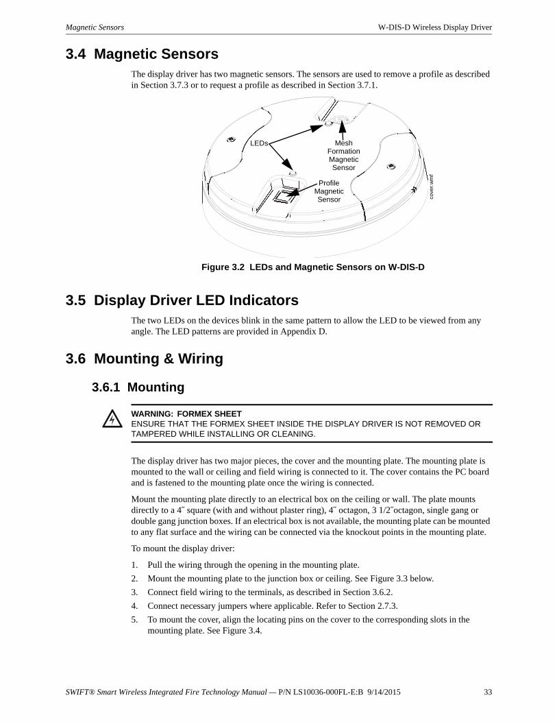
SWIFT® Smart Wireless Integrated Fire Technology Manual — P/N LS10036-000FL-E:B 9/14/2015 33
Magnetic Sensors W-DIS-D Wireless Display Driver
3.4 Magnetic SensorsThe display driver has two magnetic sensors. The sensors are used to remove a profile as described in Section 3.7.3 or to request a profile as described in Section 3.7.1.
3.5 Display Driver LED IndicatorsThe two LEDs on the devices blink in the same pattern to allow the LED to be viewed from any angle. The LED patterns are provided in Appendix D.
3.6 Mounting & Wiring
3.6.1 Mounting
The display driver has two major pieces, the cover and the mounting plate. The mounting plate is mounted to the wall or ceiling and field wiring is connected to it. The cover contains the PC board and is fastened to the mounting plate once the wiring is connected.
Mount the mounting plate directly to an electrical box on the ceiling or wall. The plate mounts directly to a 4˝ square (with and without plaster ring), 4˝ octagon, 3 1/2˝octagon, single gang or double gang junction boxes. If an electrical box is not available, the mounting plate can be mounted to any flat surface and the wiring can be connected via the knockout points in the mounting plate.
To mount the display driver:
1. Pull the wiring through the opening in the mounting plate.
2. Mount the mounting plate to the junction box or ceiling. See Figure 3.3 below.
3. Connect field wiring to the terminals, as described in Section 3.6.2.
4. Connect necessary jumpers where applicable. Refer to Section 2.7.3.
5. To mount the cover, align the locating pins on the cover to the corresponding slots in the mounting plate. See Figure 3.4.
Figure 3.2 LEDs and Magnetic Sensors on W-DIS-D
LEDs Mesh Formation Magnetic Sensor
Profile Magnetic Sensor co
ver.
wm
f
!WARNING: FORMEX SHEETENSURE THAT THE FORMEX SHEET INSIDE THE DISPLAY DRIVER IS NOT REMOVED OR TAMPERED WHILE INSTALLING OR CLEANING.
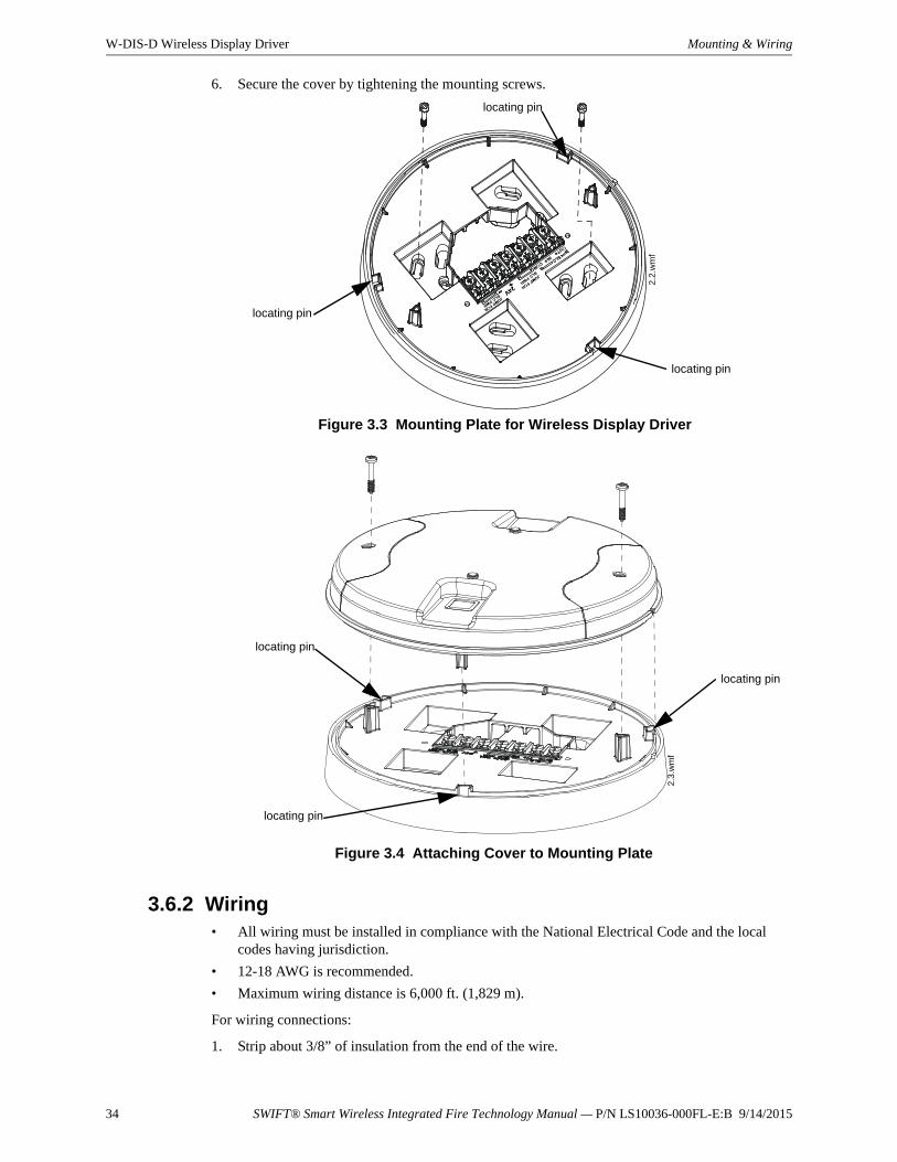
34 SWIFT® Smart Wireless Integrated Fire Technology Manual — P/N LS10036-000FL-E:B 9/14/2015
W-DIS-D Wireless Display Driver Mounting & Wiring
6. Secure the cover by tightening the mounting screws.
3.6.2 Wiring• All wiring must be installed in compliance with the National Electrical Code and the local
codes having jurisdiction.
• 12-18 AWG is recommended.
• Maximum wiring distance is 6,000 ft. (1,829 m).
For wiring connections:
1. Strip about 3/8” of insulation from the end of the wire.
Figure 3.3 Mounting Plate for Wireless Display Driver
2.2
.wm
f
locating pin
locating pin
locating pin
Figure 3.4 Attaching Cover to Mounting Plate
2.3
.wm
f
locating pin
locating pin
locating pin
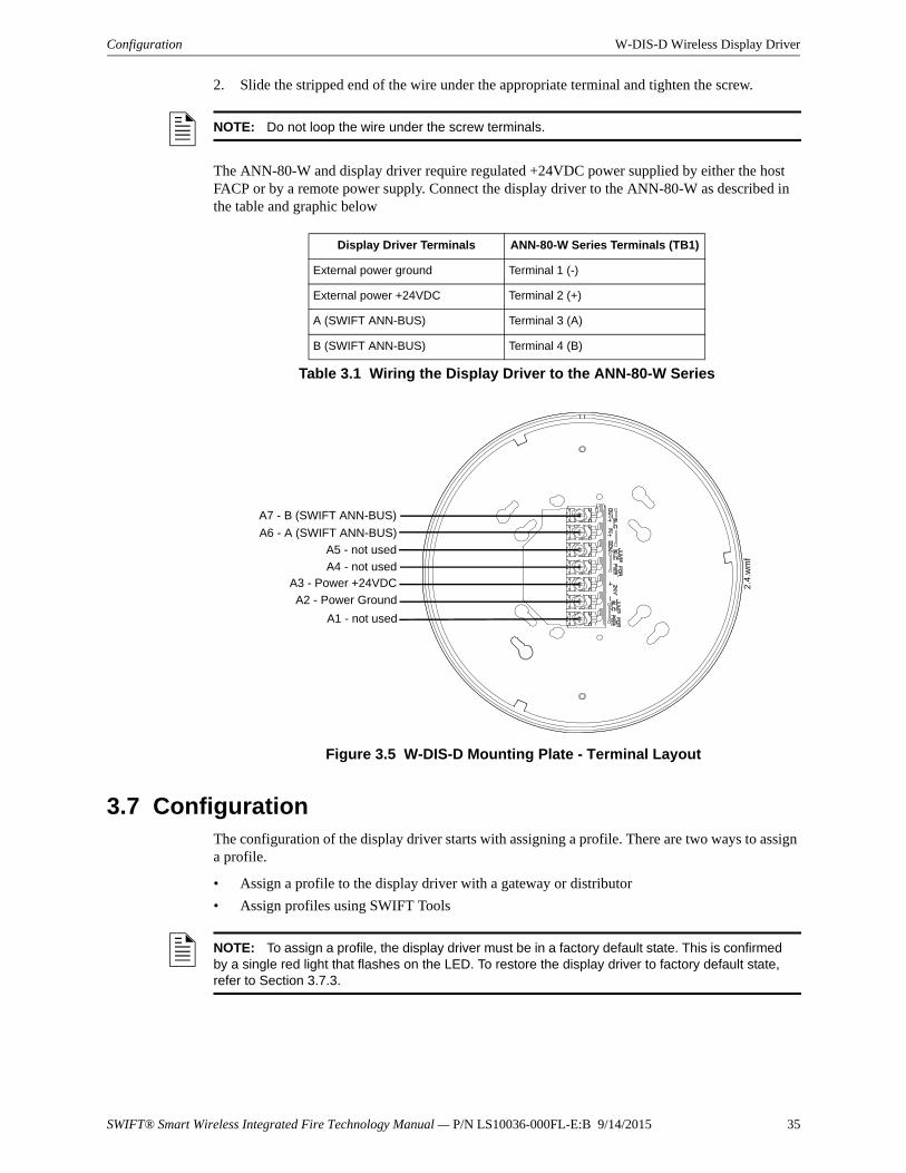
SWIFT® Smart Wireless Integrated Fire Technology Manual — P/N LS10036-000FL-E:B 9/14/2015 35
Configuration W-DIS-D Wireless Display Driver
2. Slide the stripped end of the wire under the appropriate terminal and tighten the screw.
The ANN-80-W and display driver require regulated +24VDC power supplied by either the host FACP or by a remote power supply. Connect the display driver to the ANN-80-W as described in the table and graphic below
3.7 ConfigurationThe configuration of the display driver starts with assigning a profile. There are two ways to assign a profile.
• Assign a profile to the display driver with a gateway or distributor
• Assign profiles using SWIFT Tools
NOTE: Do not loop the wire under the screw terminals.
Display Driver Terminals ANN-80-W Series Terminals (TB1)
External power ground Terminal 1 (-)
External power +24VDC Terminal 2 (+)
A (SWIFT ANN-BUS) Terminal 3 (A)
B (SWIFT ANN-BUS) Terminal 4 (B)
Table 3.1 Wiring the Display Driver to the ANN-80-W Series
Figure 3.5 W-DIS-D Mounting Plate - Terminal Layout
A7 - B (SWIFT ANN-BUS)
A6 - A (SWIFT ANN-BUS)
A5 - not used
A4 - not usedA3 - Power +24VDC
A2 - Power Ground
A1 - not used
2.4
.wm
f
NOTE: To assign a profile, the display driver must be in a factory default state. This is confirmed by a single red light that flashes on the LED. To restore the display driver to factory default state, refer to Section 3.7.3.
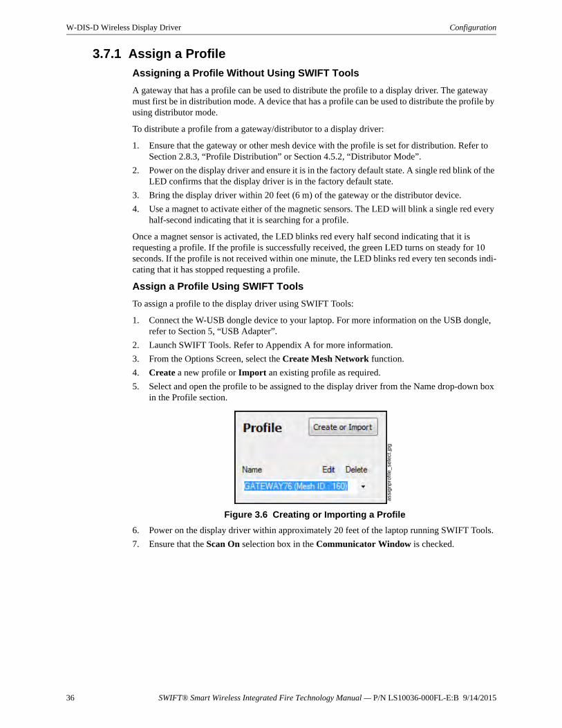
36 SWIFT® Smart Wireless Integrated Fire Technology Manual — P/N LS10036-000FL-E:B 9/14/2015
W-DIS-D Wireless Display Driver Configuration
3.7.1 Assign a Profile
Assigning a Profile Without Using SWIFT Tools
A gateway that has a profile can be used to distribute the profile to a display driver. The gateway must first be in distribution mode. A device that has a profile can be used to distribute the profile by using distributor mode.
To distribute a profile from a gateway/distributor to a display driver:
1. Ensure that the gateway or other mesh device with the profile is set for distribution. Refer to Section 2.8.3, “Profile Distribution” or Section 4.5.2, “Distributor Mode”.
2. Power on the display driver and ensure it is in the factory default state. A single red blink of the LED confirms that the display driver is in the factory default state.
3. Bring the display driver within 20 feet (6 m) of the gateway or the distributor device.
4. Use a magnet to activate either of the magnetic sensors. The LED will blink a single red every half-second indicating that it is searching for a profile.
Once a magnet sensor is activated, the LED blinks red every half second indicating that it is requesting a profile. If the profile is successfully received, the green LED turns on steady for 10 seconds. If the profile is not received within one minute, the LED blinks red every ten seconds indi-cating that it has stopped requesting a profile.
Assign a Profile Using SWIFT Tools
To assign a profile to the display driver using SWIFT Tools:
1. Connect the W-USB dongle device to your laptop. For more information on the USB dongle, refer to Section 5, “USB Adapter”.
2. Launch SWIFT Tools. Refer to Appendix A for more information.
3. From the Options Screen, select the Create Mesh Network function.
4. Create a new profile or Import an existing profile as required.
5. Select and open the profile to be assigned to the display driver from the Name drop-down box in the Profile section.
6. Power on the display driver within approximately 20 feet of the laptop running SWIFT Tools.
7. Ensure that the Scan On selection box in the Communicator Window is checked.
Figure 3.6 Creating or Importing a Profile
assi
gnpr
ofile
_se
lect
.jpg
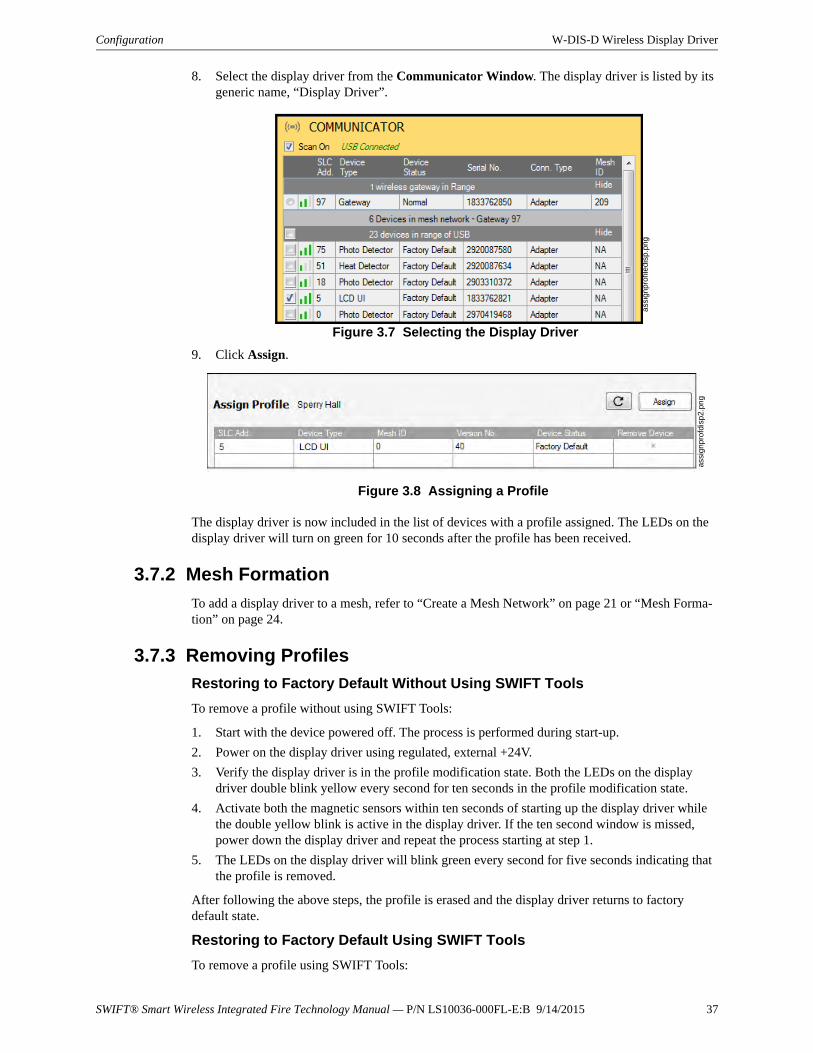
SWIFT® Smart Wireless Integrated Fire Technology Manual — P/N LS10036-000FL-E:B 9/14/2015 37
Configuration W-DIS-D Wireless Display Driver
8. Select the display driver from the Communicator Window. The display driver is listed by its generic name, “Display Driver”.
9. Click Assign.
The display driver is now included in the list of devices with a profile assigned. The LEDs on the display driver will turn on green for 10 seconds after the profile has been received.
3.7.2 Mesh Formation
To add a display driver to a mesh, refer to “Create a Mesh Network” on page 21 or “Mesh Forma-tion” on page 24.
3.7.3 Removing Profiles
Restoring to Factory Default Without Using SWIFT Tools
To remove a profile without using SWIFT Tools:
1. Start with the device powered off. The process is performed during start-up.
2. Power on the display driver using regulated, external +24V.
3. Verify the display driver is in the profile modification state. Both the LEDs on the display driver double blink yellow every second for ten seconds in the profile modification state.
4. Activate both the magnetic sensors within ten seconds of starting up the display driver while the double yellow blink is active in the display driver. If the ten second window is missed, power down the display driver and repeat the process starting at step 1.
5. The LEDs on the display driver will blink green every second for five seconds indicating that the profile is removed.
After following the above steps, the profile is erased and the display driver returns to factory default state.
Restoring to Factory Default Using SWIFT Tools
To remove a profile using SWIFT Tools:
Figure 3.7 Selecting the Display Driver
assi
gn
pro
file
disp
.pn
g
Figure 3.8 Assigning a Profile
assi
gn
pro
fdis
p2.p
ng
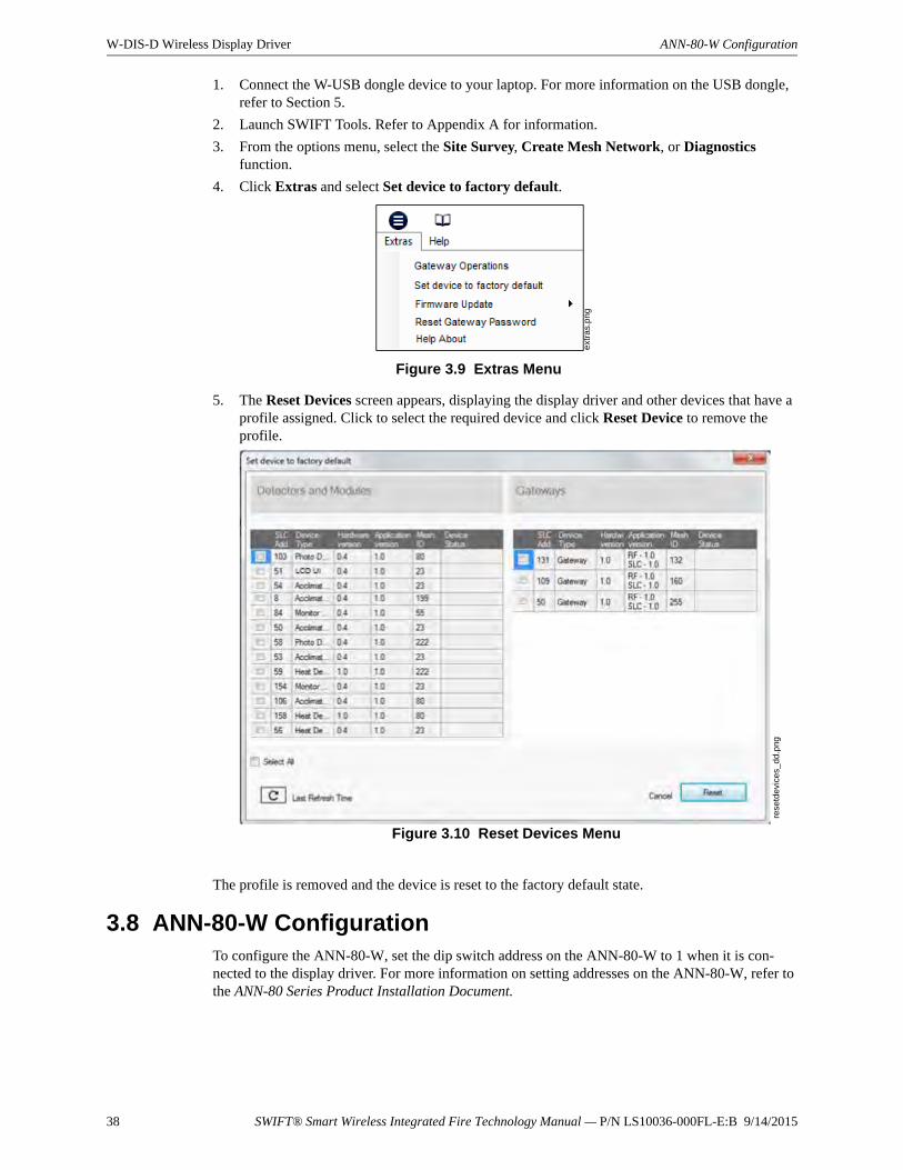
38 SWIFT® Smart Wireless Integrated Fire Technology Manual — P/N LS10036-000FL-E:B 9/14/2015
W-DIS-D Wireless Display Driver ANN-80-W Configuration
1. Connect the W-USB dongle device to your laptop. For more information on the USB dongle, refer to Section 5.
2. Launch SWIFT Tools. Refer to Appendix A for information.
3. From the options menu, select the Site Survey, Create Mesh Network, or Diagnostics function.
4. Click Extras and select Set device to factory default.
5. The Reset Devices screen appears, displaying the display driver and other devices that have a profile assigned. Click to select the required device and click Reset Device to remove the profile.
The profile is removed and the device is reset to the factory default state.
3.8 ANN-80-W ConfigurationTo configure the ANN-80-W, set the dip switch address on the ANN-80-W to 1 when it is con-nected to the display driver. For more information on setting addresses on the ANN-80-W, refer to the ANN-80 Series Product Installation Document.
ext
ras.
pn
g
Figure 3.9 Extras Menu
rese
tde
vice
s_d
d.p
ng
Figure 3.10 Reset Devices Menu
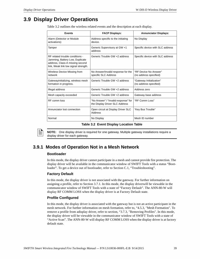
SWIFT® Smart Wireless Integrated Fire Technology Manual — P/N LS10036-000FL-E:B 9/14/2015 39
Display Driver Operations W-DIS-D Wireless Display Driver
3.9 Display Driver OperationsTable 3.2 outlines the wireless related events and the description at each display.
3.9.1 Modes of Operation Not in a Mesh Network
Bootloader
In this mode, the display driver cannot participate in a mesh and cannot provide fire protection. The display driver will be available in the communicator window of SWIFT Tools with a status “Boot-loader”. To get a device out of bootloader, refer to Section C.1, “Troubleshooting”.
Factory Default
In this mode, the display driver is not associated with the gateway. For further information on assigning a profile, refer to Section 3.7.1. In this mode, the display driverwill be viewable in the communicator window of SWIFT Tools with a state of “Factory Default”. The ANN-80-W will display RF COMM LOSS when the display driver is at Factory Default state.
Profile Configured
In this mode, the display driver is associated with the gateway but is not an active participant in the mesh network. For further information on mesh formation, refer to, “4.5.3, "Mesh Formation". To remove a profile from adisplay driver, refer to section, “3.7.3, "Removing Profiles". In this mode, the display driver will be viewable in the communicator window of SWIFT Tools with a state of “Active Scan”. The ANN-80-W will display RF COMM LOSS when the display driver is at factory default state.
Events FACP Displays: Annunciator Displays:
Alarm (Detector or Module activations)
Address specific to the initiating device.
No Display
Tamper Generic Supervisory at GW +1 address
Specific device with SLC address
RF related trouble conditions - Jamming, Battery Low, Duplicate address, Class-A missing second link, Weak link low signal strength.
Generic Trouble GW +2 address Specific device with SLC address
Wireless Device Missing from network
No Answer/Invalid response for the specific SLC Address
“RF Device No Answer” (no address specified)
Gatewayinitializing, wireless mesh formation in progress.
Generic Trouble GW +2 address “Gateway Initialization”(no address specified)
Illegal address Generic Trouble GW +2 address Address zero
Mesh capacity exceeded Generic Trouble GW +2 address Gateway base address
RF comm loss “No Answer” / “Invalid response” for the Display Driver SLC Address
“RF Comm Loss”
Annunciator lost connection Open circuit at Display Driver SLC Address
“Key Bus Trouble”
Normal No Display Mesh ID number
Table 3.2 Event Display Location Table
NOTE: One display driver is required for one gateway. Multiple gateway installations require a display driver for each gateway.
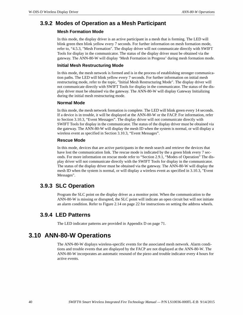
40 SWIFT® Smart Wireless Integrated Fire Technology Manual — P/N LS10036-000FL-E:B 9/14/2015
W-DIS-D Wireless Display Driver ANN-80-W Operations
3.9.2 Modes of Operation as a Mesh Participant
Mesh Formation Mode
In this mode, the display driver is an active participant in a mesh that is forming. The LED will blink green then blink yellow every 7 seconds. For further information on mesh formation mode, refer to, “4.5.3, "Mesh Formation". The display driver will not communicate directly with SWIFT Tools for display in the communicator. The status of the display driver must be obtained via the gateway. The ANN-80-W will display ‘Mesh Formation in Progress’ during mesh formation mode.
Initial Mesh Restructuring Mode
In this mode, the mesh network is formed and is in the process of establishing stronger communica-tion paths. The LED will blink yellow every 7 seconds. For further information on initial mesh restructuring mode, refer to the topic, "Initial Mesh Restructuring Mode". The display driver will not communicate directly with SWIFT Tools for display in the communicator. The status of the dis-play driver must be obtained via the gateway. The ANN-80-W will display Gateway Initializing during the initial mesh restructuring mode.
Normal Mode
In this mode, the mesh network formation is complete. The LED will blink green every 14 seconds. If a device is in trouble, it will be displayed at the ANN-80-W or the FACP. For information, refer to Section 3.10.3, “Event Messages”. The display driver will not communicate directly with SWIFT Tools for display in the communicator. The status of the display driver must be obtained via the gateway. The ANN-80-W will display the mesh ID when the system is normal, or will display a wireless event as specified in Section 3.10.3, “Event Messages”.
Rescue Mode
In this mode, devices that are active participants in the mesh search and retrieve the devices that have lost the communication link. The rescue mode is indicated by the a green blink every 7 sec-onds. For more information on rescue mode refer to “Section 2.9.1, “Modes of Operation” The dis-play driver will not communicate directly with the SWIFT Tools for display in the communicator. The status of the display driver must be obtained via the gateway. The ANN-80-W will display the mesh ID when the system is normal, or will display a wireless event as specified in 3.10.3, "Event Messages".
3.9.3 SLC Operation
Program the SLC point on the display driver as a monitor point. When the communication to the ANN-80-W is missing or disrupted, the SLC point will indicate an open circuit but will not initiate an alarm condition. Refer to Figure 2.14 on page 22 for instructions on setting the address wheels.
3.9.4 LED Patterns
The LED indicator patterns are provided in Appendix D on page 71.
3.10 ANN-80-W OperationsThe ANN-80-W displays wireless-specific events for the associated mesh network. Alarm condi-tions and trouble events that are displayed by the FACP are not displayed at the ANN-80-W. The ANN-80-W incorporates an automatic resound of the piezo and trouble indicator every 4 hours for active events.
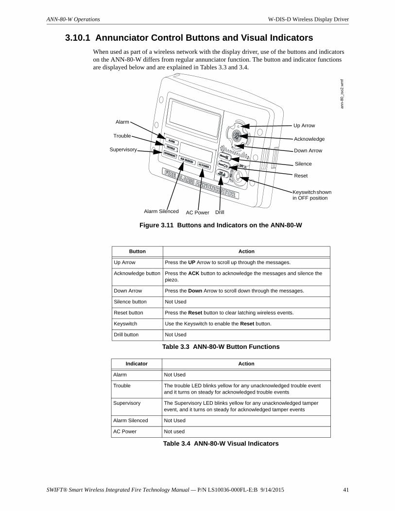
SWIFT® Smart Wireless Integrated Fire Technology Manual — P/N LS10036-000FL-E:B 9/14/2015 41
ANN-80-W Operations W-DIS-D Wireless Display Driver
3.10.1 Annunciator Control Buttons and Visual Indicators
When used as part of a wireless network with the display driver, use of the buttons and indicators on the ANN-80-W differs from regular annunciator function. The button and indicator functions are displayed below and are explained in Tables 3.3 and 3.4.
Button Action
Up Arrow Press the UP Arrow to scroll up through the messages.
Acknowledge button Press the ACK button to acknowledge the messages and silence the piezo.
Down Arrow Press the Down Arrow to scroll down through the messages.
Silence button Not Used
Reset button Press the Reset button to clear latching wireless events.
Keyswitch Use the Keyswitch to enable the Reset button.
Drill button Not Used
Table 3.3 ANN-80-W Button Functions
Indicator Action
Alarm Not Used
Trouble The trouble LED blinks yellow for any unacknowledged trouble event and it turns on steady for acknowledged trouble events
Supervisory The Supervisory LED blinks yellow for any unacknowledged tamper event, and it turns on steady for acknowledged tamper events
Alarm Silenced Not Used
AC Power Not used
Table 3.4 ANN-80-W Visual Indicators
Figure 3.11 Buttons and Indicators on the ANN-80-W
Up Arrow
Acknowledge
Down Arrow
Silence
Reset
Keyswitch shown in OFF position
DrillAC PowerAlarm Silenced
Supervisory
Trouble
Alarm
ann-
80_i
so2
.wm
f
42 SWIFT® Smart Wireless Integrated Fire Technology Manual — P/N LS10036-000FL-E:B 9/14/2015
W-DIS-D Wireless Display Driver ANN-80-W Operations
3.10.2 Audible Indicators
Wireless events are sent to the FACP as generic trouble or supervisory events by the gateway. Details of those specific events are sent to the ANN-80-W by the display driver. The FACP piezo activates for the first trouble event and the first supervisory event. The FACP piezo will not activate for additional trouble or supervisory events when the initial event is still active. The ANN-80-W piezo will not activate for the first event but will sound for each event after the first event.
Press the ACK button to acknowledge the event and silence the piezo. The reset function can be enabled in the ANN-80-W using the keyswitch. To enable the reset button, insert the key into the keyswitch and turn the keyswitch counterclockwise to the ON position.
3.10.3 Event MessagesWireless network event messages are displayed on the FACP and ANN-80-W. These messages are displayed based on their occurrences. Use the up arrow and down arrow buttons to scroll through the messages. Trouble and supervisory events that are specific to a device will specify the device address on the ANN-80-W. The FACP will display a trouble condition for the gateway +2 address for any wireless trouble. The FACP will indicate an activation for the gateway +1 address for any tamper event.
RF Comm Loss
RF COMM LOSS is displayed when the display driver is not in the network. This message is dis-played if the display driver is in bootloader, factory default, or profile assigned mode but not a part of a mesh network. RF COMM LOSS is a non-latching event that will clear once the display driver joins a mesh network.
Trouble Wireless Mesh Formation In Progress
MESH FORMATION IN PROGRESS is displayed when the network is in mesh formation mode. MESH FORMATION IN PROGRESS is a non-latching trouble event that will clear once the gateway exits mesh formation mode. The ANN-80-W must join the network to show this mes-sage. If the ANN-80-W is not present in the network, RF COMM LOSS is displayed.
Low Battery Event
TROUBLE BATTERY LOW is displayed if:
• a device has a minimum of one week power left to perform the required operations.
Or
• there are less than 4 viable batteries installed.
The low battery event is a latching condition. To clear the low battery event, tamper the device and replace all four batteries. When a device is tampered, it drops out of the mesh network and attempts to rejoin as soon as the batteries are replaced and the tamper event is cleared. The wireless device and its address are displayed as a trouble on the ANN-80-W and generic trouble on the FACP. Initi-ate a RESET at the ANN-80-W to clear the low battery event.
Trouble Jamming Event
TROUBLE JAMMING displays when a device is overloaded with an interfering RF signal but is able to send outgoing messages. A jamming event is detected after 20 seconds of exposure to the jamming signal.The jamming event is displayed as a trouble event in the ANN-80-W and generic trouble event on the FACP. Jamming is a non-latching trouble. To clear the jamming trouble, remove any interference sources near the point that is reporting the trouble. For more information, refer to Appendix C.
Trouble Duplicate Address
Two wireless devices on the same mesh network that are set to the same address report a TROU-BLE DUPLICATE ADDRESS. A duplicate address is a non-latching trouble that will correct itself once the conflict has been resolved.
SWIFT® Smart Wireless Integrated Fire Technology Manual — P/N LS10036-000FL-E:B 9/14/2015 43
ANN-80-W Operations W-DIS-D Wireless Display Driver
Trouble Class A Missing 2nd Link
The TROUBLE CLASS A message denotes a single connection path from the device. The wire-less system is a class A system requiring two communication paths for normal operations. To rem-edy the class A fault, ensure adequate device spacing or the use of a repeater may be required. The wireless mesh is a self-healing network. If the trouble is not cleared within 5 minutes, additional actions may be required. Refer to the troubleshooting section for tips on resolving class A fault conditions.
Trouble Wireless Gateway Initializing
The ANN-80-W displays GATEWAY INITIALIZATION when it is restructurizing for the first time. Gateway initializing is a non-latching trouble that is active during the first mesh restructuring. The message will clear once the first mesh restructuring routine finishes.
System Normal
The ANN-80-W displays WIRELESS GW DISPLAY and the mesh ID number when the system is functioning normally and there are no wireless troubles in the system.
Supervisory Tamper
SUPERVISORY TAMPER indicates that a detector is not firmly attached to its base or the cover plate is not properly attached to a module. The Tamper events are displayed as supervisory events on the ANN-80-W, using the device address, and generic supervisory events on the FACP, using Base +2 of the gateway address. Tamper is a latching condition that requires a reset at the ANN-80-W to clear.
Trouble Weak Link Low Signal Strength
TROUBLE WEAK LINK indicates insufficient signal strength. To resolve a weak link, ensure there is adequate device spacing. The use of a repeater may be required. Tamper any devices when moving them to a new location. Restart mesh formation once the repeater is installed or devices rejoin the network, after the tamper is cleared. The gateway will re-evaluate the signal strength con-nectivity with the neighboring devices and select suitable signal paths during the subsequent mesh restructuring.
Key Bus Trouble
A KEY BUS TROUBLE indicates that the ANN-80-W has lost connection with the display driver.
Capacity Exceeded
CAPACITY EXCEEDED indicates that there are already fifty devices present in the mesh and one more device is trying to join the network.
Maximum Gateways
MAXIMUM GATEWAYS EXCEEDED indicates that the number of overlapping gateways exceeds the limit of 4. The trouble will be cleared only when the number of overlapping gateways is reduced to 4 or less. Refer to Appendix C for more information.
RF Device No Answer
RF Device No Answer is a generic trouble event to indicate one or more wireless devices currently or previously have lost communication with the mesh network. RF Device No Answer is a latching event that requires a reset at the ANN-80-W. RF Device No Answer will be indicated 180 seconds after a device has lost communication with the mesh network. The device may have lost communi-cation due to a tamper event, dead battery, jamming, or device drop (complete loss of communica-tion).
3.10.4 Clearing messages
The events that are non-latching will clear once the event returns to the normal state. Events that are latching require a reset at the ANN-80-W. To reset messages, press the Reset button on the ANN-80-W. Refer to Figure 3.2. To reset messages at the panel, initiate a system reset.

44 SWIFT® Smart Wireless Integrated Fire Technology Manual — P/N LS10036-000FL-E:B 9/14/2015
Notes
SWIFT® Smart Wireless Integrated Fire Technology Manual — P/N LS10036-000FL-E:B 9/14/2015 45
Section 4: Wireless Devices
4.1 DescriptionThe SWIFT Network consists of the following devices:
W-SD355 - Wireless Photoelectric Smoke Detector -FCC ID: AUBWFSSD
The wireless photoelectric smoke detector is powered by four CR123A batteries. It has a sensor head to detect smoke and LEDs to indicate the activation and trouble status.
W-SD355T - Wireless Photo/Heat Detector FCC ID: AUBWFSSD
The wireless photo/heat detector is powered by four CR123A batteries. It has a sensor head to detect heat and LEDs to indicate activation and trouble status.
W-H355R - Wireless Rate of Rise Heat Detector FCC ID: AUBWFSSD
The rate of rise heat detectors are powered by four CR123A batteries. The detectors have LEDs to indicate the activation and trouble status.
W-H355 - Wireless 135° Fixed Heat Detector FCC ID: AUBWFSSD
The fixed heat detectors are powered by four CR123A batteries. The detectors have LEDs to indi-cate the activation and trouble status.
W-MMF - Wireless Addressable Monitor Module FCC ID: AUBWFSMM
The wireless monitor module is powered by four CR123A batteries. It can be connected to a switch within three feet of its location or wired directly to the pull station. The module has LEDs to indi-cate the activation and trouble status.
W-CRF - Wireless Addressable Relay Module FCC ID: AUBWFSRM
The wireless relay module is powered by four CR123A batteries. It provides the system with a dry-contact output for activating a variety of auxiliary devices, such as fans, dampers, control equip-ment, etc. Addressability allows the dry contact to be activated, either manually or through panel programming, on a select basis. The module has an LED to indicate the activation and trouble sta-tus.
For more information on the LED indicators, refer to Section 4.6.2.
4.2 Agency Approvals
4.2.1 FCC
This device complies with part 15 of the FCC Rules. Operation is subject to the following two con-ditions:
1. This device may not cause harmful interference.
NOTE: When a wireless relay is in use, modules device count must be limited to 109 modules per loop. This includes wired and wireless modules that are on the same loop. The module address range must be within 1-109.
NOTE: When activating a wireless relay from a wireless module input source, the wireless relay must be in the same mesh network. This does not apply to wireless detectors and does not apply to wired input sources.
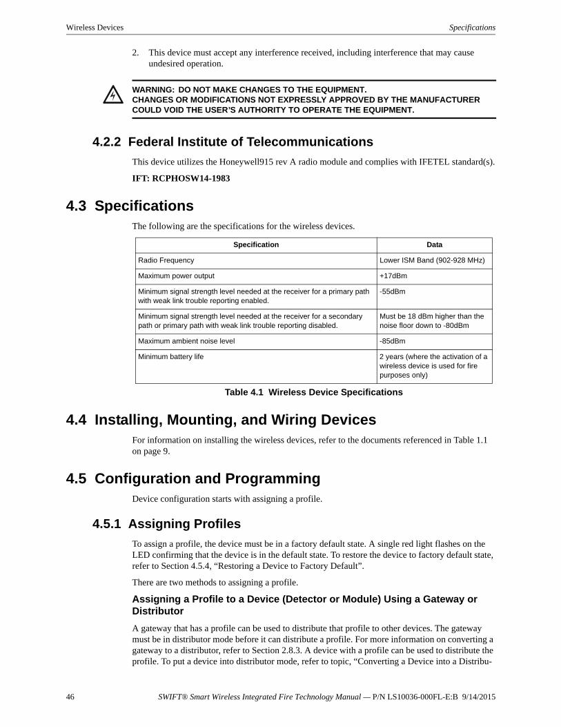
46 SWIFT® Smart Wireless Integrated Fire Technology Manual — P/N LS10036-000FL-E:B 9/14/2015
Wireless Devices Specifications
2. This device must accept any interference received, including interference that may cause undesired operation.
4.2.2 Federal Institute of Telecommunications
This device utilizes the Honeywell915 rev A radio module and complies with IFETEL standard(s).
IFT: RCPHOSW14-1983
4.3 SpecificationsThe following are the specifications for the wireless devices.
4.4 Installing, Mounting, and Wiring DevicesFor information on installing the wireless devices, refer to the documents referenced in Table 1.1 on page 9.
4.5 Configuration and ProgrammingDevice configuration starts with assigning a profile.
4.5.1 Assigning Profiles
To assign a profile, the device must be in a factory default state. A single red light flashes on the LED confirming that the device is in the default state. To restore the device to factory default state, refer to Section 4.5.4, “Restoring a Device to Factory Default”.
There are two methods to assigning a profile.
Assigning a Profile to a Device (Detector or Module) Using a Gateway or Distributor
A gateway that has a profile can be used to distribute that profile to other devices. The gateway must be in distributor mode before it can distribute a profile. For more information on converting a gateway to a distributor, refer to Section 2.8.3. A device with a profile can be used to distribute the profile. To put a device into distributor mode, refer to topic, “Converting a Device into a Distribu-
!WARNING: DO NOT MAKE CHANGES TO THE EQUIPMENT.CHANGES OR MODIFICATIONS NOT EXPRESSLY APPROVED BY THE MANUFACTURER COULD VOID THE USER’S AUTHORITY TO OPERATE THE EQUIPMENT.
Specification Data
Radio Frequency Lower ISM Band (902-928 MHz)
Maximum power output +17dBm
Minimum signal strength level needed at the receiver for a primary path with weak link trouble reporting enabled.
-55dBm
Minimum signal strength level needed at the receiver for a secondary path or primary path with weak link trouble reporting disabled.
Must be 18 dBm higher than the noise floor down to -80dBm
Maximum ambient noise level -85dBm
Minimum battery life 2 years (where the activation of a wireless device is used for fire purposes only)
Table 4.1 Wireless Device Specifications
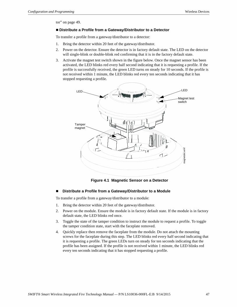
SWIFT® Smart Wireless Integrated Fire Technology Manual — P/N LS10036-000FL-E:B 9/14/2015 47
Configuration and Programming Wireless Devices
tor” on page 49.
Distribute a Profile from a Gateway/Distributor to a Detector
To transfer a profile from a gateway/distributor to a detector:
1. Bring the detector within 20 feet of the gateway/distributor.
2. Power on the detector. Ensure the detector is in factory default state. The LED on the detector will single-blink or double-blink red confirming that it is in the factory default state.
3. Activate the magnet test switch shown in the figure below. Once the magnet sensor has been activated, the LED blinks red every half second indicating that it is requesting a profile. If the profile is successfully received, the green LED turns on steady for 10 seconds. If the profile is not received within 1 minute, the LED blinks red every ten seconds indicating that it has stopped requesting a profile.
Distribute a Profile from a Gateway/Distributor to a Module
To transfer a profile from a gateway/distributor to a module:
1. Bring the detector within 20 feet of the gateway/distributor.
2. Power on the module. Ensure the module is in factory default state. If the module is in factory default state, the LED blinks red once.
3. Toggle the state of the tamper condition to instruct the module to request a profile. To toggle the tamper condition state, start with the faceplate removed.
4. Quickly replace then remove the faceplate from the module. Do not attach the mounting screws for the faceplate during this step. The LED blinks red every half second indicating that it is requesting a profile. The green LEDs turn on steady for ten seconds indicating that the profile has been assigned. If the profile is not received within 1 minute, the LED blinks red every ten seconds indicating that it has stopped requesting a profile.
Figure 4.1 Magnetic Sensor on a Detectorm
ag
netd
et.w
mf
LED LED
Magnet test switch
Tamper magnet
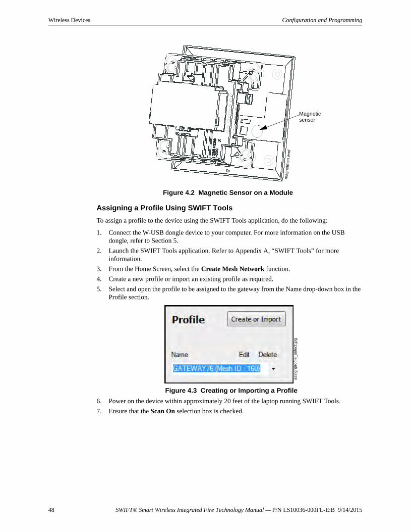
48 SWIFT® Smart Wireless Integrated Fire Technology Manual — P/N LS10036-000FL-E:B 9/14/2015
Wireless Devices Configuration and Programming
Assigning a Profile Using SWIFT Tools
To assign a profile to the device using the SWIFT Tools application, do the following:
1. Connect the W-USB dongle device to your computer. For more information on the USB dongle, refer to Section 5.
2. Launch the SWIFT Tools application. Refer to Appendix A, “SWIFT Tools” for more information.
3. From the Home Screen, select the Create Mesh Network function.
4. Create a new profile or import an existing profile as required.
5. Select and open the profile to be assigned to the gateway from the Name drop-down box in the Profile section.
6. Power on the device within approximately 20 feet of the laptop running SWIFT Tools.
7. Ensure that the Scan On selection box is checked.
Figure 4.2 Magnetic Sensor on a Module
mag
netm
on.w
mf
Magnetic sensor
Figure 4.3 Creating or Importing a Profile
assi
gn
pro
file
_se
lect
.jpg
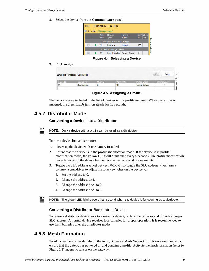
SWIFT® Smart Wireless Integrated Fire Technology Manual — P/N LS10036-000FL-E:B 9/14/2015 49
Configuration and Programming Wireless Devices
8. Select the device from the Communicator panel.
9. Click Assign.
The device is now included in the list of devices with a profile assigned. When the profile is assigned, the green LEDs turn on steady for 10 seconds.
4.5.2 Distributor Mode
Converting a Device into a Distributor
To turn a device into a distributor:
1. Power up the device with one battery installed.
2. Ensure that the device is in the profile modification mode. If the device is in profile modification mode, the yellow LED will blink once every 5 seconds. The profile modification mode times out if the device has not received a command in one minute.
3. Toggle the SLC address wheel between 0-1-0-1. To toggle the SLC address wheel, use a common screwdriver to adjust the rotary switches on the device to:
1. Set the address to 0.
2. Change the address to 1.
3. Change the address back to 0.
4. Change the address back to 1.
Converting a Distributor Back into a Device
To return a distributor device back to a network device, replace the batteries and provide a proper SLC address. A normal device requires four batteries for proper operation. It is recommended to use fresh batteries after the distributor mode.
4.5.3 Mesh Formation
To add a device to a mesh, refer to the topic, "Create a Mesh Network". To form a mesh network, ensure that the gateway is powered on and contains a profile. Activate the mesh formation (refer to Figure 2.2) magnetic sensor on the gateway.
Figure 4.4 Selecting a Device
assi
gnpr
ofile
.pn
g
Figure 4.5 Assigning a Profile
ass
ignp
rofil
e2.p
ng
NOTE: Only a device with a profile can be used as a distributor.
NOTE: The green LED blinks every half second when the device is functioning as a distributor.
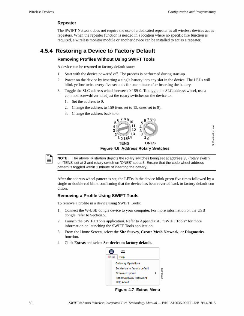
50 SWIFT® Smart Wireless Integrated Fire Technology Manual — P/N LS10036-000FL-E:B 9/14/2015
Wireless Devices Configuration and Programming
Repeater
The SWIFT Network does not require the use of a dedicated repeater as all wireless devices act as repeaters. When the repeater function is needed in a location where no specific fire function is required, a wireless monitor module or another device can be installed to act as a repeater.
4.5.4 Restoring a Device to Factory Default
Removing Profiles Without Using SWIFT Tools
A device can be restored to factory default state:
1. Start with the device powered off. The process is performed during start-up.
2. Power on the device by inserting a single battery into any slot in the device. The LEDs will blink yellow twice every five seconds for one minute after inserting the battery.
3. Toggle the SLC address wheel between 0-159-0. To toggle the SLC address wheel, use a common screwdriver to adjust the rotary switches on the device to:
1. Set the address to 0.
2. Change the address to 159 (tens set to 15, ones set to 9).
3. Change the address back to 0.
After the address wheel pattern is set, the LEDs in the device blink green five times followed by a single or double red blink confirming that the device has been reverted back to factory default con-dition.
Removing a Profile Using SWIFT Tools
To remove a profile in a device using SWIFT Tools:
1. Connect the W-USB dongle device to your computer. For more information on the USB dongle, refer to Section 5.
2. Launch the SWIFT Tools application. Refer to Appendix A, “SWIFT Tools” for more information on launching the SWIFT Tools application.
3. From the Home Screen, select the Site Survey, Create Mesh Network, or Diagnostics function.
4. Click Extras and select Set device to factory default.
TENS
8 910111213
1415012
345
6 7
ONES
8 9
012
345
6 7
Figure 4.6 Address Rotary Switches
SL
C-s
eta
dd
tph.
wm
f
NOTE: The above illustration depicts the rotary switches being set at address 35 (rotary switch on 'TENS' set at 3 and rotary switch on 'ONES’ set at 5. Ensure that the code wheel address pattern is toggled within 1 minute of inserting the battery.
ext
ras.
png
Figure 4.7 Extras Menu
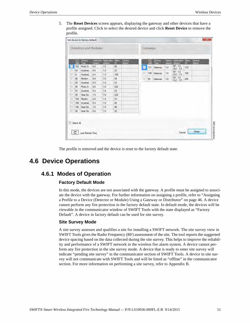
SWIFT® Smart Wireless Integrated Fire Technology Manual — P/N LS10036-000FL-E:B 9/14/2015 51
Device Operations Wireless Devices
5. The Reset Devices screen appears, displaying the gateway and other devices that have a profile assigned. Click to select the desired device and click Reset Device to remove the profile.
The profile is removed and the device is reset to the factory default state.
4.6 Device Operations
4.6.1 Modes of Operation
Factory Default Mode
In this mode, the devices are not associated with the gateway. A profile must be assigned to associ-ate the device with the gateway. For further information on assigning a profile, refer to “Assigning a Profile to a Device (Detector or Module) Using a Gateway or Distributor” on page 46. A device cannot perform any fire protection in the factory default state. In default mode, the devices will be viewable in the communicator window of SWIFT Tools with the state displayed as “Factory Default”. A device in factory default can be used for site survey.
Site Survey Mode
A site survey assesses and qualifies a site for installing a SWIFT network. The site survey view in SWIFT Tools gives the Radio Frequency (RF) assessment of the site. The tool reports the suggested device spacing based on the data collected during the site survey. This helps to improve the reliabil-ity and performance of a SWIFT network in the wireless fire alarm system. A device cannot per-form any fire protection in the site survey mode. A device that is ready to enter site survey will indicate “pending site survey” in the communicator section of SWIFT Tools. A device in site sur-vey will not communicate with SWIFT Tools and will be listed as “offline” in the communicator section. For more information on performing a site survey, refer to Appendix B.
Figure 4.8 Reset Devices Screen
rese
tde
vice
s.jp
g
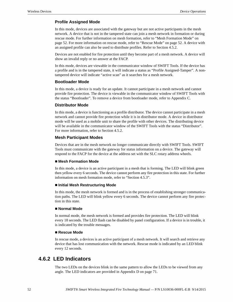
52 SWIFT® Smart Wireless Integrated Fire Technology Manual — P/N LS10036-000FL-E:B 9/14/2015
Wireless Devices Device Operations
Profile Assigned Mode
In this mode, devices are associated with the gateway but are not active participants in the mesh network. A device that is not in the tampered state can join a mesh network in formation or during rescue mode. For further information on mesh formation, refer to “Mesh Formation Mode” on page 52. For more information on rescue mode, refer to “Rescue Mode” on page 52. A device with an assigned profile can also be used to distribute profiles. Refer to Section 4.5.2.
Devices are not enabled for fire protection until they become part of a mesh network. A device will show an invalid reply or no answer at the FACP.
In this mode, devices are viewable in the communicator window of SWIFT Tools. If the device has a profile and is in the tampered state, it will indicate a status as “Profile Assigned-Tamper”. A non-tampered device will indicate “active scan” as it searches for a mesh network.
Bootloader Mode
In this mode, a device is ready for an update. It cannot participate in a mesh network and cannot provide fire protection. The device is viewable in the communicator window of SWIFT Tools with the status “Bootloader”. To remove a device from bootloader mode, refer to Appendix C.
Distributor Mode
In this mode, a device is functioning as a profile distributor. The device cannot participate in a mesh network and cannot provide fire protection while it is in distributor mode. A device in distributor mode will be used as a mobile unit to share the profile with other devices. The distributing device will be available in the communicator window of the SWIFT Tools with the status “Distributor”. For more information, refer to Section 4.5.2.
Mesh Participant Modes
Devices that are in the mesh network no longer communicate directly with SWIFT Tools. SWIFT Tools must communicate with the gateway for status information on a device. The gateway will respond to the FACP for the device at the address set with the SLC rotary address wheels.
Mesh Formation Mode
In this mode, a device is an active participant in a mesh that is forming. The LED will blink green then yellow every 6 seconds. The device cannot perform any fire protection in this state. For further information on mesh formation mode, refer to “Section 4.5.3”.
Initial Mesh Restructuring Mode
In this mode, the mesh network is formed and is in the process of establishing stronger communica-tion paths. The LED will blink yellow every 6 seconds. The device cannot perform any fire protec-tion in this state.
Normal Mode
In normal mode, the mesh network is formed and provides fire protection. The LED will blink every 18 seconds. The LED flash can be disabled by panel configuration. If a device is in trouble, it is indicated by the trouble messages.
Rescue Mode
In rescue mode, a devices is an active participant of a mesh network. It will search and retrieve any device that has lost communication with the network. Rescue mode is indicated by an LED blink every 12 seconds.
4.6.2 LED Indicators
The two LEDs on the devices blink in the same pattern to allow the LEDs to be viewed from any angle. The LED indicators are provided in Appendix D on page 71.

SWIFT® Smart Wireless Integrated Fire Technology Manual — P/N LS10036-000FL-E:B 9/14/2015 53
Notes
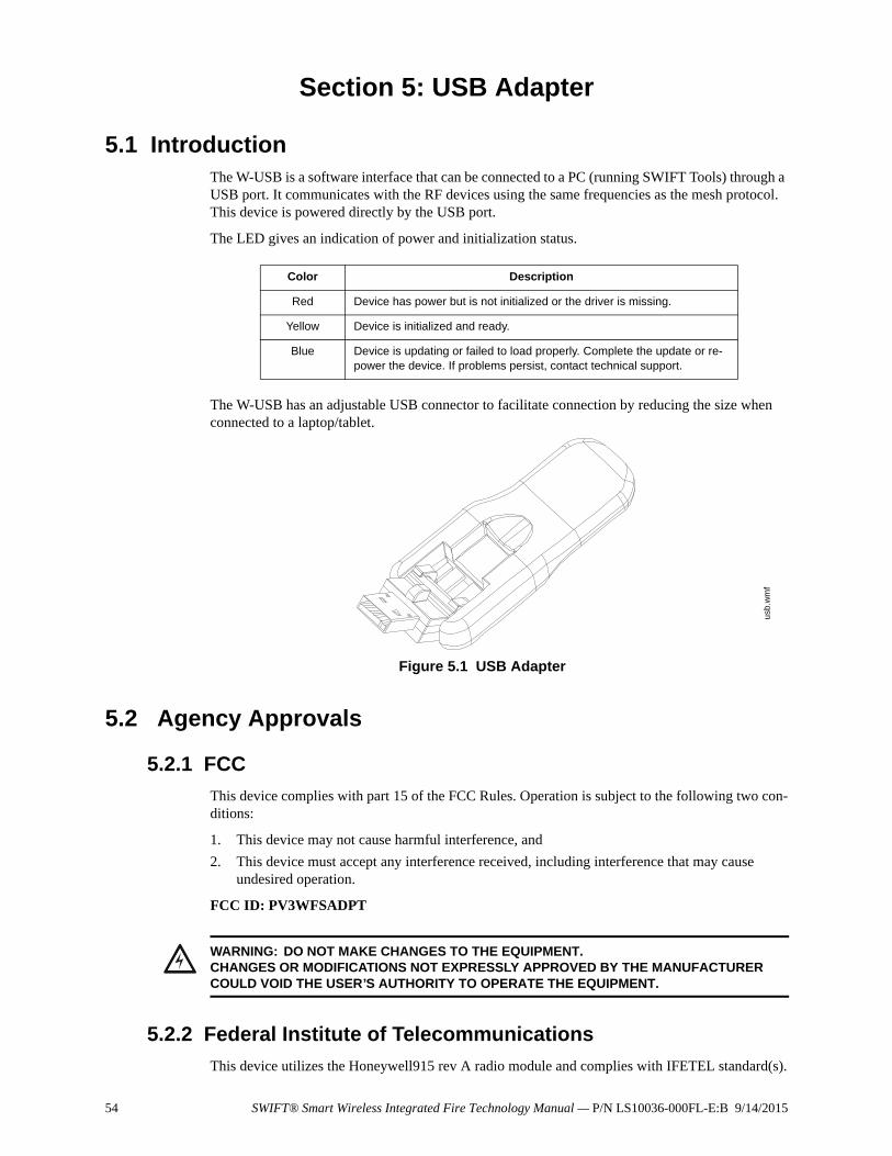
54 SWIFT® Smart Wireless Integrated Fire Technology Manual — P/N LS10036-000FL-E:B 9/14/2015
Section 5: USB Adapter
5.1 IntroductionThe W-USB is a software interface that can be connected to a PC (running SWIFT Tools) through a USB port. It communicates with the RF devices using the same frequencies as the mesh protocol. This device is powered directly by the USB port.
The LED gives an indication of power and initialization status.
The W-USB has an adjustable USB connector to facilitate connection by reducing the size when connected to a laptop/tablet.
5.2 Agency Approvals
5.2.1 FCC
This device complies with part 15 of the FCC Rules. Operation is subject to the following two con-ditions:
1. This device may not cause harmful interference, and
2. This device must accept any interference received, including interference that may cause undesired operation.
FCC ID: PV3WFSADPT
5.2.2 Federal Institute of Telecommunications
This device utilizes the Honeywell915 rev A radio module and complies with IFETEL standard(s).
Color Description
Red Device has power but is not initialized or the driver is missing.
Yellow Device is initialized and ready.
Blue Device is updating or failed to load properly. Complete the update or re-power the device. If problems persist, contact technical support.
Figure 5.1 USB Adapter
usb.
wm
f
!WARNING: DO NOT MAKE CHANGES TO THE EQUIPMENT.CHANGES OR MODIFICATIONS NOT EXPRESSLY APPROVED BY THE MANUFACTURER COULD VOID THE USER’S AUTHORITY TO OPERATE THE EQUIPMENT.
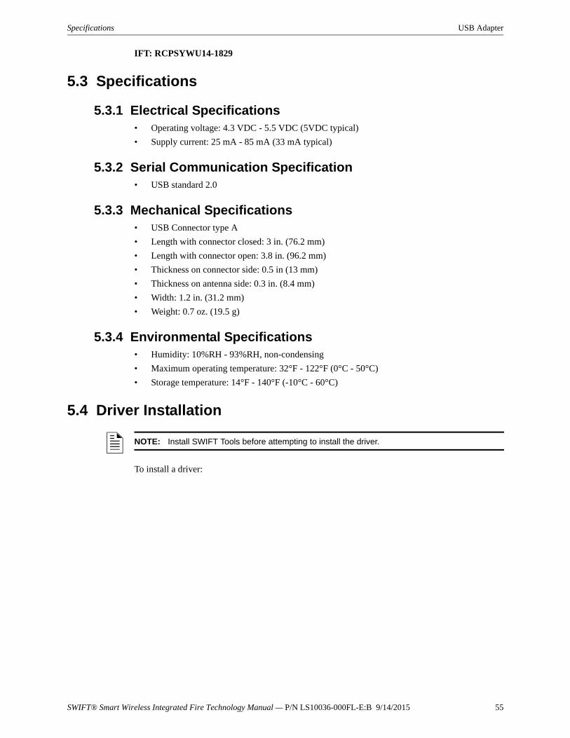
SWIFT® Smart Wireless Integrated Fire Technology Manual — P/N LS10036-000FL-E:B 9/14/2015 55
Specifications USB Adapter
IFT: RCPSYWU14-1829
5.3 Specifications
5.3.1 Electrical Specifications• Operating voltage: 4.3 VDC - 5.5 VDC (5VDC typical)
• Supply current: 25 mA - 85 mA (33 mA typical)
5.3.2 Serial Communication Specification• USB standard 2.0
5.3.3 Mechanical Specifications• USB Connector type A
• Length with connector closed: 3 in. (76.2 mm)
• Length with connector open: 3.8 in. (96.2 mm)
• Thickness on connector side: 0.5 in (13 mm)
• Thickness on antenna side: 0.3 in. (8.4 mm)
• Width: 1.2 in. (31.2 mm)
• Weight: 0.7 oz. (19.5 g)
5.3.4 Environmental Specifications• Humidity: 10%RH - 93%RH, non-condensing
• Maximum operating temperature: 32°F - 122°F (0°C - 50°C)
• Storage temperature: 14°F - 140°F (-10°C - 60°C)
5.4 Driver Installation
To install a driver:
NOTE: Install SWIFT Tools before attempting to install the driver.
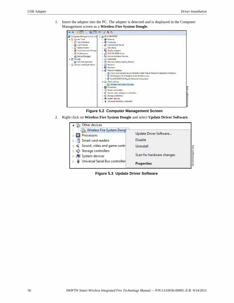
56 SWIFT® Smart Wireless Integrated Fire Technology Manual — P/N LS10036-000FL-E:B 9/14/2015
USB Adapter Driver Installation
1. Insert the adapter into the PC. The adapter is detected and is displayed in the Computer Management screen as a Wireless Fire System Dongle.
2. Right click on Wireless Fire System Dongle and select Update Driver Software.
Figure 5.2 Computer Management Screen
dev
cem
ana
ger1
.pn
g
Figure 5.3 Update Driver Software
dev
cem
ana
ger2
.pn
g
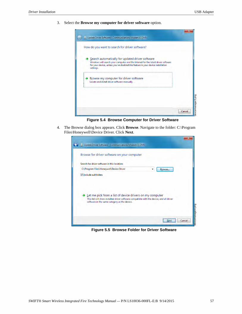
SWIFT® Smart Wireless Integrated Fire Technology Manual — P/N LS10036-000FL-E:B 9/14/2015 57
Driver Installation USB Adapter
3. Select the Browse my computer for driver software option.
4. The Browse dialog box appears. Click Browse. Navigate to the folder: C:\Program Files\Honeywell\Device Driver. Click Next.
Figure 5.4 Browse Computer for Driver Software
devc
eman
ager
3.p
ng
Figure 5.5 Browse Folder for Driver Software
dev
cem
ana
ger4
.pn
g
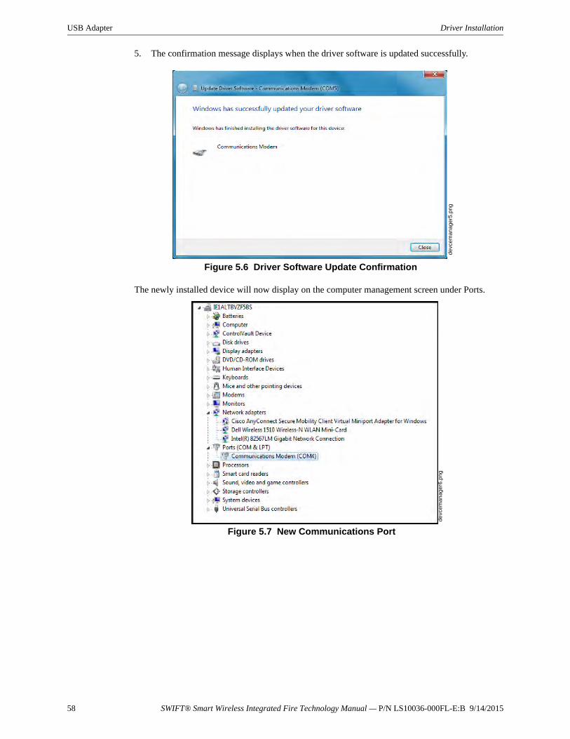
58 SWIFT® Smart Wireless Integrated Fire Technology Manual — P/N LS10036-000FL-E:B 9/14/2015
USB Adapter Driver Installation
5. The confirmation message displays when the driver software is updated successfully.
The newly installed device will now display on the computer management screen under Ports.
Figure 5.6 Driver Software Update Confirmation
devc
eman
ager
5.p
ng
Figure 5.7 New Communications Port
devc
eman
ager
6.p
ng
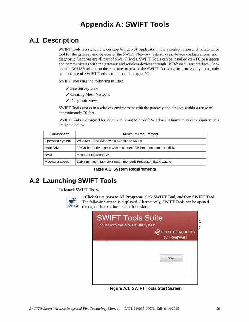
SWIFT® Smart Wireless Integrated Fire Technology Manual — P/N LS10036-000FL-E:B 9/14/2015 59
Appendix A: SWIFT Tools
A.1 DescriptionSWIFT Tools is a standalone desktop Windows® application. It is a configuration and maintenance tool for the gateway and devices of the SWIFT Network. Site surveys, device configurations, and diagnostic functions are all part of SWIFT Tools. SWIFT Tools can be installed on a PC or a laptop and communicates with the gateway and wireless devices through USB-based user interface. Con-nect the W-USB adapter to the computer to invoke the SWIFT Tools application. At any point, only one instance of SWIFT Tools can run on a laptop or PC.
SWIFT Tools has the following utilities:
Site Survey view
Creating Mesh Network
Diagnostic view
SWIFT Tools works in a wireless environment with the gateway and devices within a range of approximately 20 feet.
SWIFT Tools is designed for systems running Microsoft Windows. Minimum system requirements are listed below.
A.2 Launching SWIFT ToolsTo launch SWIFT Tools,
1.Click Start, point to All Programs, click SWIFT Tool, and then SWIFT Tool. The following screen is displayed. Alternatively, SWIFT Tools can be opened through a shortcut located on the desktop.
Component Minimum Requirement
Operating System Windows 7 and Windows 8 (32 bit and 64 bit)
Hard Drive 20 GB hard drive space with minimum 1GB free space on hard disk.
RAM Minimum 512MB RAM
Processor speed 1GHz minimum (2.4 GHz recommended) Processor, 512K Cache
Table A.1 System Requirements
star
tfl.j
pg
Figure A.1 SWIFT Tools Start Screen
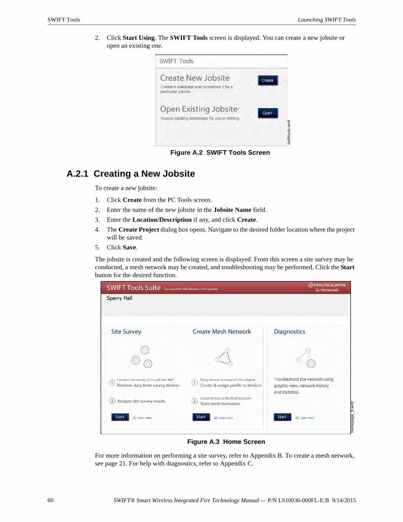
60 SWIFT® Smart Wireless Integrated Fire Technology Manual — P/N LS10036-000FL-E:B 9/14/2015
SWIFT Tools Launching SWIFT Tools
2. Click Start Using. The SWIFT Tools screen is displayed. You can create a new jobsite or open an existing one.
A.2.1 Creating a New Jobsite
To create a new jobsite:
1. Click Create from the PC Tools screen.
2. Enter the name of the new jobsite in the Jobsite Name field.
3. Enter the Location/Description if any, and click Create.
4. The Create Project dialog box opens. Navigate to the desired folder location where the project will be saved.
5. Click Save.
The jobsite is created and the following screen is displayed. From this screen a site survey may be conducted, a mesh network may be created, and troubleshooting may be performed. Click the Start button for the desired function.
For more information on performing a site survey, refer to Appendix B. To create a mesh network, see page 21. For help with diagnostics, refer to Appendix C.
swift
tool
s.w
mf
Figure A.2 SWIFT Tools Screen
hom
ep
age_
fl.w
mf
Figure A.3 Home Screen
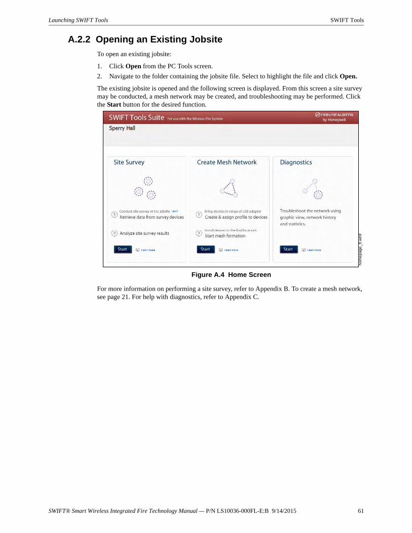
SWIFT® Smart Wireless Integrated Fire Technology Manual — P/N LS10036-000FL-E:B 9/14/2015 61
Launching SWIFT Tools SWIFT Tools
A.2.2 Opening an Existing Jobsite
To open an existing jobsite:
1. Click Open from the PC Tools screen.
2. Navigate to the folder containing the jobsite file. Select to highlight the file and click Open.
The existing jobsite is opened and the following screen is displayed. From this screen a site survey may be conducted, a mesh network may be created, and troubleshooting may be performed. Click the Start button for the desired function.
For more information on performing a site survey, refer to Appendix B. To create a mesh network, see page 21. For help with diagnostics, refer to Appendix C.
hom
epag
e_f
l.wm
f
Figure A.4 Home Screen

62 SWIFT® Smart Wireless Integrated Fire Technology Manual — P/N LS10036-000FL-E:B 9/14/2015
Appendix B: Site SurveyA site survey is recommended to assess and qualify the site prior to installing a SWIFT network. The site survey consists of a link quality test and RF scan test. After both tests are completed, the results of the site survey can be obtained using SWIFT Tools. The information provided by SWIFT Tools is used for site qualification, maximum device spacing identification, and configuring the network. This helps to improve the reliability and performance of the wireless network in the wire-less fire alarm system.
B.1 Conduct a Site Survey
B.1.1 Link Quality Test
A link quality test is a quick and repeatable test that provides immediate feedback on device con-nectivity. The link quality test sends data from one device to another to test for data loss and mea-sure the signal strength. In a link test, the device addresses are set in the range of 001 to 150. A minimum of two devices are needed to conduct a link quality test.
A link test is conducted between two or more devices. The link test starts when a device that is in the “pending site survey” state has its tamper condition cleared. The device will send a burst of data to the next address lower than its own address. The lower addressed device will automatically return the link quality test results for display using the device LEDs. For example, clearing the tam-per condition on a detector set to address 2 (D002) will make the detector enter the link quality test. D002 will send a burst of data to a device at address 001 (either detector or module). The device at address 001 will measure the signal strength and count the data received in the burst and return the information to D002. The results of the test will be displayed at D002. The test can be repeated by tampering D002 to return it to the “pending site survey” mode and then clearing the tamper.
Basic Requirements of a Link Quality Test
To conduct a link test:
two or more devices (detectors) are required.
devices must be in factory default state. The LEDs on the device will blink single or double red to confirm it is in the factory default state. Refer to Section 4.5.4 on page 50 for more information on setting the device to factory default state.
device addresses can bet set in the range of 1 to 150.
Conduct a Link Quality Test
To conduct a link quality test:
1. Remove the batteries from the devices that will be used for the site survey and set the SLC address. To set an SLC address, use a common screwdriver to adjust the rotary switches on the device.
a. For the first device used in a site survey, set the SLC address to 001.
b. For each subsequent device, use the next highest SLC address (up to address 150). For example, the first device was set to 001, set the second device to 002, and the third device to 003, etc.
2. Bring the first device (001) to the first location to conduct the test.
3. Insert one battery into the device. Inserting more than one battery deters the device from entering the site survey mode. The device is ready for site survey mode if the LED blinks yellow every 5 seconds.
4. Clear the tamper condition to proceed with the test. To clear the tamper condition on a detector, insert the detector into the base and twist to lock the detector completely into the base. To clear the tamper condition on a module, attach the faceplate to the module. When the tamper is cleared, the LEDs on the device starts blinking yellow every ½ second for approximately 20 seconds. The results appear in approximately 20 seconds and the LEDs on the first device
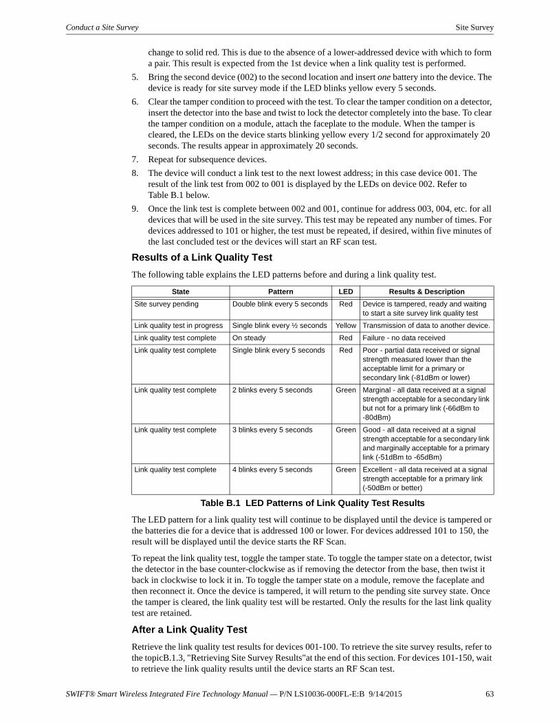
SWIFT® Smart Wireless Integrated Fire Technology Manual — P/N LS10036-000FL-E:B 9/14/2015 63
Conduct a Site Survey Site Survey
change to solid red. This is due to the absence of a lower-addressed device with which to form a pair. This result is expected from the 1st device when a link quality test is performed.
5. Bring the second device (002) to the second location and insert one battery into the device. The device is ready for site survey mode if the LED blinks yellow every 5 seconds.
6. Clear the tamper condition to proceed with the test. To clear the tamper condition on a detector, insert the detector into the base and twist to lock the detector completely into the base. To clear the tamper condition on a module, attach the faceplate to the module. When the tamper is cleared, the LEDs on the device starts blinking yellow every 1/2 second for approximately 20 seconds. The results appear in approximately 20 seconds.
7. Repeat for subsequence devices.
8. The device will conduct a link test to the next lowest address; in this case device 001. The result of the link test from 002 to 001 is displayed by the LEDs on device 002. Refer to Table B.1 below.
9. Once the link test is complete between 002 and 001, continue for address 003, 004, etc. for all devices that will be used in the site survey. This test may be repeated any number of times. For devices addressed to 101 or higher, the test must be repeated, if desired, within five minutes of the last concluded test or the devices will start an RF scan test.
Results of a Link Quality Test
The following table explains the LED patterns before and during a link quality test.
The LED pattern for a link quality test will continue to be displayed until the device is tampered or the batteries die for a device that is addressed 100 or lower. For devices addressed 101 to 150, the result will be displayed until the device starts the RF Scan.
To repeat the link quality test, toggle the tamper state. To toggle the tamper state on a detector, twist the detector in the base counter-clockwise as if removing the detector from the base, then twist it back in clockwise to lock it in. To toggle the tamper state on a module, remove the faceplate and then reconnect it. Once the device is tampered, it will return to the pending site survey state. Once the tamper is cleared, the link quality test will be restarted. Only the results for the last link quality test are retained.
After a Link Quality Test
Retrieve the link quality test results for devices 001-100. To retrieve the site survey results, refer to the topicB.1.3, "Retrieving Site Survey Results"at the end of this section. For devices 101-150, wait to retrieve the link quality results until the device starts an RF Scan test.
State Pattern LED Results & Description
Site survey pending Double blink every 5 seconds Red Device is tampered, ready and waiting to start a site survey link quality test
Link quality test in progress Single blink every ½ seconds Yellow Transmission of data to another device.
Link quality test complete On steady Red Failure - no data received
Link quality test complete Single blink every 5 seconds Red Poor - partial data received or signal strength measured lower than the acceptable limit for a primary or secondary link (-81dBm or lower)
Link quality test complete 2 blinks every 5 seconds Green Marginal - all data received at a signal strength acceptable for a secondary link but not for a primary link (-66dBm to -80dBm)
Link quality test complete 3 blinks every 5 seconds Green Good - all data received at a signal strength acceptable for a secondary link and marginally acceptable for a primary link (-51dBm to -65dBm)
Link quality test complete 4 blinks every 5 seconds Green Excellent - all data received at a signal strength acceptable for a primary link (-50dBm or better)
Table B.1 LED Patterns of Link Quality Test Results
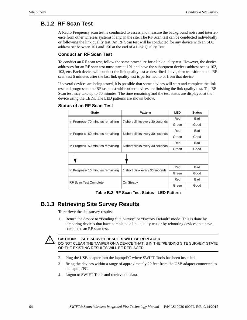
64 SWIFT® Smart Wireless Integrated Fire Technology Manual — P/N LS10036-000FL-E:B 9/14/2015
Site Survey Conduct a Site Survey
B.1.2 RF Scan Test
A Radio Frequency scan test is conducted to assess and measure the background noise and interfer-ence from other wireless systems if any, in the site. The RF Scan test can be conducted individually or following the link quality test. An RF Scan test will be conducted for any device with an SLC address set between 101 and 150 at the end of a Link Quality Test.
Conduct an RF Scan Test
To conduct an RF scan test, follow the same procedure for a link quality test. However, the device addresses for an RF scan test must start at 101 and have the subsequent devices address set as 102, 103, etc. Each device will conduct the link quality test as described above, then transition to the RF scan test 5 minutes after the last link quality test is performed to or from that device.
If several devices are being tested, it is possible that some devices will start and complete the link test and progress to the RF scan test while other devices are finishing the link quality test. The RF Scan test may take up to 70 minutes. The time remaining and the test status are displayed at the device using the LEDs. The LED patterns are shown below.
Status of an RF Scan Test
B.1.3 Retrieving Site Survey ResultsTo retrieve the site survey results:
1. Return the device to “Pending Site Survey” or “Factory Default” mode. This is done by tampering devices that have completed a link quality test or by rebooting devices that have completed an RF scan test.
2. Plug the USB adapter into the laptop/PC where SWIFT Tools has been installed.
3. Bring the devices within a range of approximately 20 feet from the USB adapter connected to the laptop/PC.
4. Logon to SWIFT Tools and retrieve the data.
State Pattern LED Status
In Progress- 70 minutes remaining 7 short blinks every 30 secondsRed Bad
Green Good
In Progress- 60 minutes remaining 6 short blinks every 30 secondsRed Bad
Green Good
In Progress- 50 minutes remaining 5 short blinks every 30 secondsRed Bad
Green Good
In Progress- 10 minutes remaining 1 short blink every 30 secondsRed Bad
Green Good
RF Scan Test Complete On SteadyRed Bad
Green Good
Table B.2 RF Scan Test Status - LED Pattern
! CAUTION: SITE SURVEY RESULTS WILL BE REPLACEDDO NOT CLEAR THE TAMPER ON A DEVICE THAT IS IN THE “PENDING SITE SURVEY” STATE OR THE EXISTING RESULTS WILL BE REPLACED.

SWIFT® Smart Wireless Integrated Fire Technology Manual — P/N LS10036-000FL-E:B 9/14/2015 65
Notes
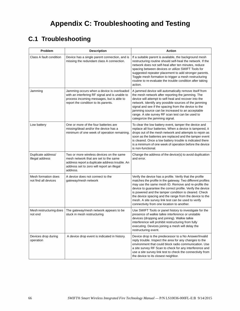
66 SWIFT® Smart Wireless Integrated Fire Technology Manual — P/N LS10036-000FL-E:B 9/14/2015
Appendix C: Troubleshooting and Testing
C.1 Troubleshooting
Problem Description Action
Class A fault condition Device has a single parent connection, and is missing the redundant class A connection.
If a suitable parent is available, the background mesh restructuring routine should self-heal the network. If the network does not self-heal after ten minutes, reduce spacing between devices or utilize SWIFT Tools for suggested repeater placement to add stronger parents. Toggle mesh formation to trigger a mesh restructuring routine to re-evaluate the trouble condition after taking action.
Jamming Jamming occurs when a device is overloaded with an interfering RF signal and is unable to process incoming messages, but is able to report the condition to its parents.
A jammed device will automatically remove itself from the mesh network after reporting the jamming. The device will attempt to self-heal and recover into the network. Identify any possible sources of the jamming signal and see if the spacing from the device to the jamming source can be increased to an acceptable range. A site survey RF scan test can be used to categorize the jamming signal.
Low battery One or more of the four batteries are missing/dead and/or the device has a minimum of one week of operation remaining.
To clear the low battery event, tamper the device and replace all four batteries. When a device is tampered, it drops out of the mesh network and attempts to rejoin as soon as the batteries are replaced and the tamper event is cleared. Once a low battery trouble is indicated there is a minimum of one week of operation before the device is non-functional.
Duplicate address/ Illegal address
Two or more wireless devices on the same mesh network that are set to the same address report a duplicate address trouble. An address set to zero will report an illegal address.
Change the address of the device(s) to avoid duplication and error.
Mesh formation does not find all devices
A device does not connect to the gateway/mesh network
Verify the device has a profile. Verify that the profile matches the profile in the gateway. Two different profiles may use the same mesh ID. Remove and re-profile the device to guarantee the correct profile. Verify the device is powered and the tamper condition is cleared. Check the device spacing and the range from the device to the mesh. A site survey link test can be used to verify connectivity from one location to another.
Mesh restructuring does not end
The gateway/mesh network appears to be stuck in mesh restructuring
Use SWIFT Tools or panel history to investigate for the presence of walkie talkie interference or unstable devices (dropping and joining). Walkie talkie interference will prohibit restructuring from fully executing. Devices joining a mesh will delay the restructuring event.
Devices drop during operation
A device drop event is indicated in history. Device drop is the predecessor to a No Answer/Invalid reply trouble. Inspect the area for any changes to the environment that could block radio communication. Use a site survey RF Scan to check for any interference and use a site survey link test to check the connectivity from the device to its closest neighbor.
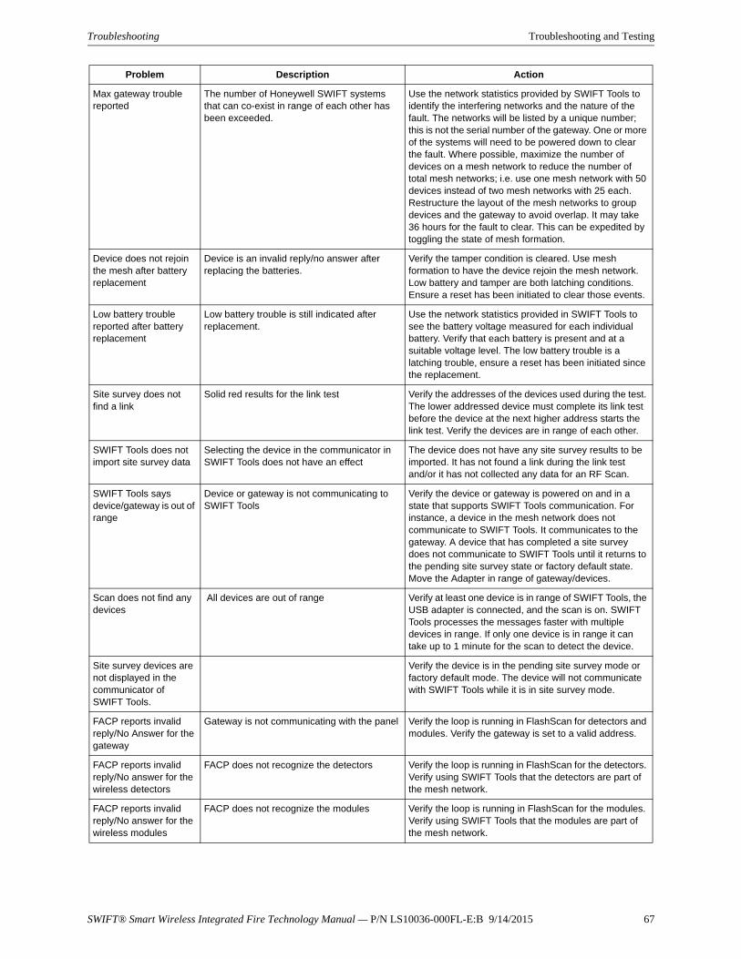
SWIFT® Smart Wireless Integrated Fire Technology Manual — P/N LS10036-000FL-E:B 9/14/2015 67
Troubleshooting Troubleshooting and Testing
Max gateway trouble reported
The number of Honeywell SWIFT systems that can co-exist in range of each other has been exceeded.
Use the network statistics provided by SWIFT Tools to identify the interfering networks and the nature of the fault. The networks will be listed by a unique number; this is not the serial number of the gateway. One or more of the systems will need to be powered down to clear the fault. Where possible, maximize the number of devices on a mesh network to reduce the number of total mesh networks; i.e. use one mesh network with 50 devices instead of two mesh networks with 25 each. Restructure the layout of the mesh networks to group devices and the gateway to avoid overlap. It may take 36 hours for the fault to clear. This can be expedited by toggling the state of mesh formation.
Device does not rejoin the mesh after battery replacement
Device is an invalid reply/no answer after replacing the batteries.
Verify the tamper condition is cleared. Use mesh formation to have the device rejoin the mesh network. Low battery and tamper are both latching conditions. Ensure a reset has been initiated to clear those events.
Low battery trouble reported after battery replacement
Low battery trouble is still indicated after replacement.
Use the network statistics provided in SWIFT Tools to see the battery voltage measured for each individual battery. Verify that each battery is present and at a suitable voltage level. The low battery trouble is a latching trouble, ensure a reset has been initiated since the replacement.
Site survey does not find a link
Solid red results for the link test Verify the addresses of the devices used during the test. The lower addressed device must complete its link test before the device at the next higher address starts the link test. Verify the devices are in range of each other.
SWIFT Tools does not import site survey data
Selecting the device in the communicator in SWIFT Tools does not have an effect
The device does not have any site survey results to be imported. It has not found a link during the link test and/or it has not collected any data for an RF Scan.
SWIFT Tools says device/gateway is out of range
Device or gateway is not communicating to SWIFT Tools
Verify the device or gateway is powered on and in a state that supports SWIFT Tools communication. For instance, a device in the mesh network does not communicate to SWIFT Tools. It communicates to the gateway. A device that has completed a site survey does not communicate to SWIFT Tools until it returns to the pending site survey state or factory default state. Move the Adapter in range of gateway/devices.
Scan does not find any devices
All devices are out of range Verify at least one device is in range of SWIFT Tools, the USB adapter is connected, and the scan is on. SWIFT Tools processes the messages faster with multiple devices in range. If only one device is in range it can take up to 1 minute for the scan to detect the device.
Site survey devices are not displayed in the communicator of SWIFT Tools.
Verify the device is in the pending site survey mode or factory default mode. The device will not communicate with SWIFT Tools while it is in site survey mode.
FACP reports invalid reply/No Answer for the gateway
Gateway is not communicating with the panel Verify the loop is running in FlashScan for detectors and modules. Verify the gateway is set to a valid address.
FACP reports invalid reply/No answer for the wireless detectors
FACP does not recognize the detectors Verify the loop is running in FlashScan for the detectors. Verify using SWIFT Tools that the detectors are part of the mesh network.
FACP reports invalid reply/No answer for the wireless modules
FACP does not recognize the modules Verify the loop is running in FlashScan for the modules. Verify using SWIFT Tools that the modules are part of the mesh network.
Problem Description Action
68 SWIFT® Smart Wireless Integrated Fire Technology Manual — P/N LS10036-000FL-E:B 9/14/2015
Troubleshooting and Testing Testing the Gateway and Devices
C.2 Testing the Gateway and DevicesThe gateway must be tested after installation and be part of a periodic maintenance program. The testing methods must satisfy the Authority Having Jurisdiction (AHJ). The gateway provides opti-mum performance when tested and maintained in compliance with NFPA 72 ordinances.
C.2.1 Testing LED Indicators
For more information on LED indicators, refer to Appendix D, “LED Indicators”, on page 71.
C.3 Testing the Wireless NetworkUsing the SWIFT Tools application, users can:
• Diagnose and troubleshoot the wireless network and connectivity of the devices.
• Monitor the wireless network topology, quality of the communication links between the devices, live and historical event reports for troubleshooting purposes.
• View the parent-child relationship and the signal strength between the two devices, and identify the device that has lost the communication link with the wireless network.
In addition, SWIFT Tools:
• Communicates with the gateway to retrieve live information about the connectivity and status of the devices.
• Stores the wireless network data such as network map, parent-child information, device information, history events, and network statistics.
The SWIFT Tools application allows retrieval of the following information for diagnosing and troubleshooting purposes.
• Network Topology
• History of Events
• Network Snapshots
• Network Statistics
• Device Attributes
Device does not receive a profile
A profile request has been initiated but timed out before receiving a profile
Ensure the gateway or distributor is still in distributor mode. Ensure the device is in range of the gateway or distributor. If there are multiple devices in range, the might be interfering with the profile transfer. Move the distributor and device to a different area or shut down the peripheral devices.
Application download fails
SWIFT Tools failed to finish a download Verify the number of devices in range of the USB adapter during the download does not exceed the recommended limit of 10 devices. Verify the device is in range and powered on during the download process.
Device is in bootloader Device/Gateway is indicating the LED pattern for bootloader and it is indicated as being in bootloader in the communicator of SWIFT Tools.
The device failed to load or initialize the application. Reboot the device. If it is still in bootloader, the application will need to be updated using SWIFT Tools. If problem persists, contact technical support.
Key Bus trouble The ANN-80 has lost connection with the display driver.
Check the connection between the ANN-80 and the display driver and reboot the display driver..
Problem Description Action
SWIFT® Smart Wireless Integrated Fire Technology Manual — P/N LS10036-000FL-E:B 9/14/2015 69
Testing the Wireless Network Troubleshooting and Testing
C.3.1 Network Topology
Parent-Child Devices
The parent-child relationship between the devices in the wireless network is displayed using the directional arrows.
Orphan Devices
A device that is not linked with any other device in the wireless topology is an orphan device. The device is represented as an orphan device due to one of the following reasons:
• The device was originally a part of the wireless network and was dropped.
• When the network topology was retrieved, the device detail was not retrieved.
• The network connections are saturated and parent-child connection with the device is not established.
Class A Compliance
Each device must comply with Class A guidelines. Every device must have two parent devices to be compliant with the Class A guidelines.
Selecting a device from the graphical representation and clicking either left or right allows you to view the following details. The Network Topology window allows you to click either left or right on any connected or orphan device.
C.3.2 History Events
History events of the wireless network can be retrieved and viewed using SWIFT Tools for trouble-shooting purposes. This report provides information on when the device gets connected with the wireless network, mode change, and slot change details.
C.3.3 Network Snapshots
Network snapshots can be retrieved and viewed using SWIFT Tools for troubleshooting purposes. The network snapshot helps to analyze how the wireless network is functioning over a period of time.
C.3.4 Network Statistics
Network statistics of the wireless network can be retrieved and viewed using SWIFT Tools for troubleshooting purposes. The network statistics provide information on the attributes and RSSI of a device. The attributes provide information on the retransmission count and device re-join events. The retransmission count is the number of times a device retransmits the wireless signal. The device re-join events is the number of times the devices get disconnected from the wireless network and get connected with the wireless network. The RSSI of a device displays the parent-child rela-tionship between the devices.
NOTE: The device image in SWIFT Tools is altered to depict that it does not meet the required guidelines.
NOTE: Class A guidelines are not applicable to the gateway.

70 SWIFT® Smart Wireless Integrated Fire Technology Manual — P/N LS10036-000FL-E:B 9/14/2015
Troubleshooting and Testing Testing the Wireless Network
C.3.5 Device Attributes
Device attributes can be retrieved and viewed using SWIFT Tools for troubleshooting purposes. The attributes of a device such as low indication, removal indication, level, tamper fault, and others are retrieved.
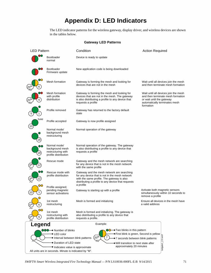
SWIFT® Smart Wireless Integrated Fire Technology Manual — P/N LS10036-000FL-E:B 9/14/2015 71
Appendix D: LED IndicatorsThe LED indicator patterns for the wireless gateway, display driver, and wireless devices are shown in the tables below.
LED Pattern Condition Action Required
Bootloader normal
Bootloader Firmware update
Mesh formation
Mesh formation with profile distribution
Profile removed
Profile accepted
Normal mode/background mesh restructuring
Normal mode/background mesh restructuring with profile distribution
Rescue mode
Device is ready to update
New application code is being downloaded
Gateway is forming the mesh and looking for devices that are not in the mesh
Wait until all devices join the mesh and then terminate mesh formation
Gateway is forming the mesh and looking for devices that are not in the mesh. The gateway is also distributing a profile to any device that requests a profile
Wait until all devices join the mesh and then terminate mesh formation or wait until the gateway automatically terminates mesh formation
Gateway has returned to the factory default state
Gateway is now profile assigned
Normal operation of the gateway
Normal operation of the gateway. The gateway is also distributing a profile to any device that requests a profile
Gateway and the mesh network are searching for any device that is not in the mesh network with the same profile
LegendNumber of blinksLED colorInterval between blink patterns
Duration of LED state
Indicates value is approximate
Two blinks in this patternFirst blink is green, Second is yellow
7 seconds between blink patterns
Will transition to next state after approximately 20 minutes
Example:
All units are in seconds. Minute is indicated by “M”. ledg
ate
1_2
.0.w
mf
620M
620M
15
10
18
18
123M
123M
Rescue mode with profile distribution
Gateway and the mesh network are searching for any device that is not in the mesh network with the same profile. The gateway is also distributing a profile to any device that requests a profile
Solid
720M
Gateway LED Patterns
10 1
5M 6
5M 6
Profile assigned; pending magnetic sensor activations
1st mesh restructuring
1st mesh restructuring with profile distribution
Gateway is starting up with a profile Activate both magnetic sensors simultaneously within 10 seconds to remove a profile
Mesh is formed and initializing
Mesh is formed and initializing. The gateway is also distributing a profile to any device that requests a profile.
Ensure all devices in the mesh have a valid address
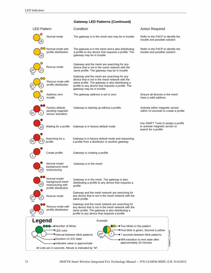
72 SWIFT® Smart Wireless Integrated Fire Technology Manual — P/N LS10036-000FL-E:B 9/14/2015
LED Indicators
18
18
4
10 1
10
60 0.5
1
720M
LED Pattern Condition Action Required
Normal mode
Normal mode with profile distribution
Address zero trouble
Factory default; pending magnetic sensor activation
Waiting for a profile
Searching for a profile
The gateway is in the mesh and may be in trouble Refer to the FACP to identify the trouble and possible solution
The gateway is in the mesh and is also distributing a profile to any device that requests a profile. The gateway may be in trouble
The gateway address is set to zero
Gateway is starting up without a profile
Gateway is in factory default mode
Gateway is in factory default mode and requesting a profile from a distributor or another gateway
LegendNumber of blinks
LED color
Interval between blink patterns
Duration of LED state
Indicates value is approximate
Two blinks in this pattern
First blink is green, Second is yellow
7 seconds between blink patterns
Will transition to next state after approximately 20 minutes
Example:
All units are in seconds. Minute is indicated by “M”.
led
gate
2_2
.0.w
mf
Create profile Gateway is creating a profile
Refer to the FACP to identify the trouble and possible solution
Ensure all devices in the mesh have a valid address
Activate either magnetic sensor within 10 seconds to create a profile
Use SWIFT Tools to assign a profile or activate magnetic sensor to search for a profile
Gateway LED Patterns (Continued)
Rescue modeGateway and the mesh are searching for any device that is not in the mesh network with the same profile. The gateway may be in trouble123M
123M
Rescue mode with profile distribution
Gateway and the mesh are searching for any device that is not in the mesh network with the same profile. The gateway is also distributing a profile to any device that requests a profile. The gateway may be in trouble
Normal mode/background mesh restructuring
Normal mode/background mesh restructuring with profile distribution
Rescue mode
Gateway is in the mesh
Gateway is in the mesh. The gateway is also distributing a profile to any device that requests a profile
Gateway and the mesh network are searching for any device that is not in the mesh network with the same profile
18
18
123M
123M
Rescue mode with profile distribution
Gateway and the mesh network are searching for any device that is not in the mesh network with the same profile. The gateway is also distributing a profile to any device that requests a profile
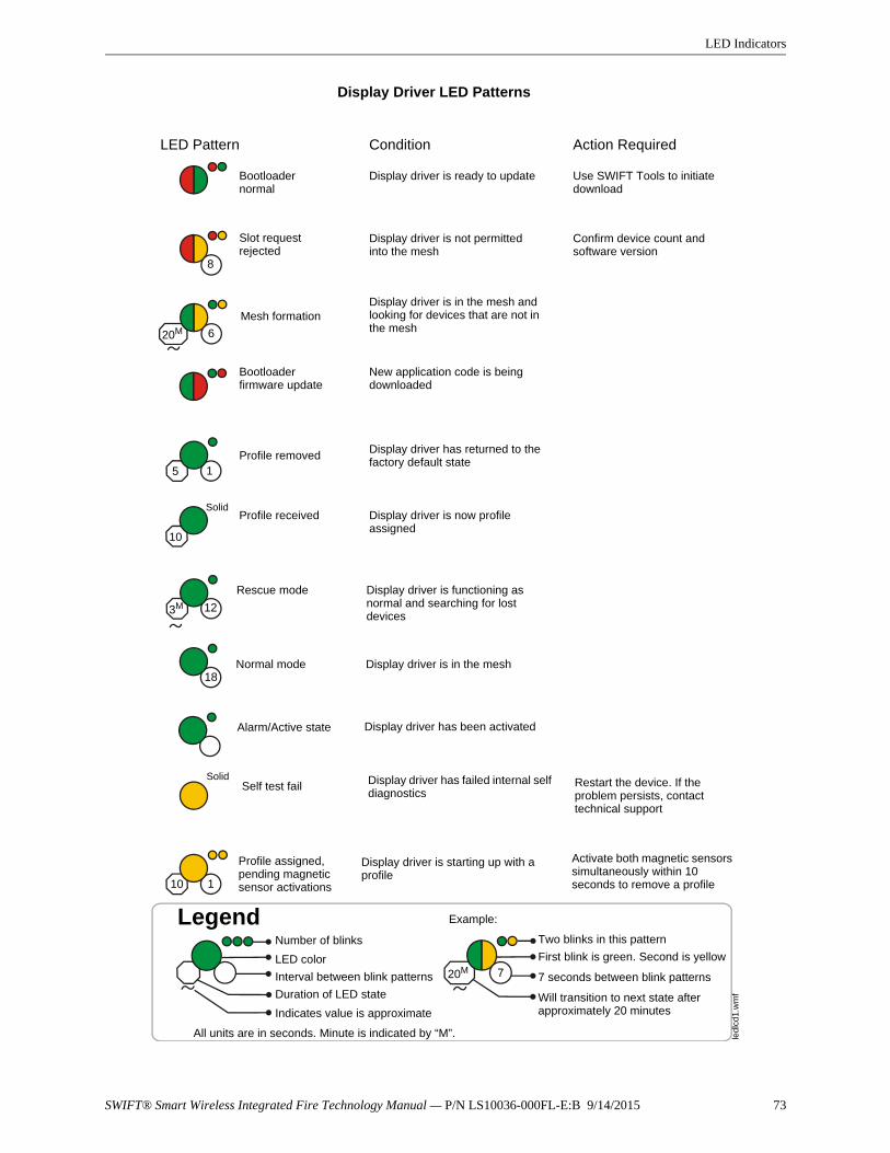
SWIFT® Smart Wireless Integrated Fire Technology Manual — P/N LS10036-000FL-E:B 9/14/2015 73
LED Indicators
LED Pattern Condition Action Required
Bootloader normal
Slot request rejected
Mesh formation
Bootloader firmware update
Profile removed
Profile received
Rescue mode
Normal mode
Self test fail
Display driver is ready to update Use SWIFT Tools to initiate download
Display driver is not permitted into the mesh
Display driver is in the mesh and looking for devices that are not in the mesh
New application code is being downloaded
Display driver has returned to the factory default state
Display driver is now profile assigned
Display driver is functioning as normal and searching for lost devices
Display driver is in the mesh
Display driver has failed internal self diagnostics
LegendNumber of blinks
LED color
Interval between blink patterns
Duration of LED state
Indicates value is approximate
Two blinks in this pattern
First blink is green. Second is yellow
7 seconds between blink patterns
Will transition to next state after approximately 20 minutes
Example:
All units are in seconds. Minute is indicated by “M”. ledl
cd1
.wm
f
Profile assigned, pending magnetic sensor activations
Display driver is starting up with a profile
Confirm device count and software version
Restart the device. If the problem persists, contact technical support
Activate both magnetic sensors simultaneously within 10 seconds to remove a profile
8
620M
15
10
3M 12
Solid
Solid
18
10 1
20M 7
Display Driver LED Patterns
Alarm/Active state Display driver has been activated
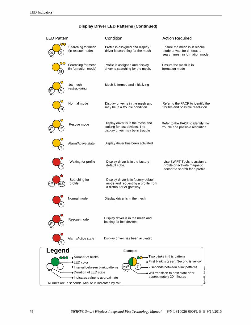
74 SWIFT® Smart Wireless Integrated Fire Technology Manual — P/N LS10036-000FL-E:B 9/14/2015
LED Indicators
LED Pattern Condition Action Required
Searching for mesh (in rescue mode)
Searching for mesh (in formation mode)
1st mesh restructuring
Normal mode
Waiting for profile
Searching for profile
Profile is assigned and display driver is searching for the mesh
Ensure the mesh is in rescue mode or wait for timeout to search mesh in formation mode
Profile is assigned and display driver is searching for the mesh.
Mesh is formed and initializing
Display driver is in the mesh and may be in a trouble condition
Display driver is in the factory default state.
Display driver is in factory default mode and requesting a profile from a distributor or gateway.
LegendNumber of blinks
LED color
Interval between blink patterns
Duration of LED state
Indicates value is approximate
Two blinks in this pattern
First blink is green. Second is yellow
7 seconds between blink patterns
Will transition to next state after approximately 20 minutes
Example:
All units are in seconds. Minute is indicated by “M”. led
lcd2
_2.
0.w
mf
Ensure the mesh is in formation mode
Display Driver LED Patterns (Continued)
Refer to the FACP to identify the trouble and possible resolution
Use SWIFT Tools to assign a profile or activate magnetic sensor to search for a profile.
90 3
25
5M 6
18
10
0.51M
720M
Rescue mode Display driver is in the mesh and looking for lost devices. The display driver may be in trouble
123M
Alarm/Active state3
Display driver has been activated
Refer to the FACP to identify the trouble and possible resolution
Normal mode Display driver is in the mesh
18
Rescue mode Display driver is in the mesh and looking for lost devices123M
Alarm/Active state3
Display driver has been activated
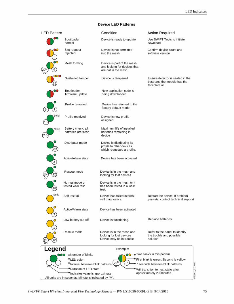
SWIFT® Smart Wireless Integrated Fire Technology Manual — P/N LS10036-000FL-E:B 9/14/2015 75
LED Indicators
LED Pattern Condition Action Required
Bootloader normal
Slot request rejected
Mesh forming
Sustained tamper
Bootloader firmware update
Profile received
Battery check: all batteries are fresh
Profile removed
Device is ready to update
Device is not permitted into the mesh
Device is part of the mesh and looking for devices that are not in the mesh
New application code is being downloaded
Device is now profile assigned
Maximum life of installed batteries remaining in device
Device has returned to the factory default mode
LegendNumber of blinks
LED color
Interval between blink patterns
Duration of LED state
Indicates value is approximate
Two blinks in this pattern
First blink is green. Second is yellow
7 seconds between blink patterns
Will transition to next state after approximately 20 minutes
Example:
All units are in seconds. Minute is indicated by “M”.
Confirm device count and software version
Device is tampered
Solid
Solid
Distributor mode Device is distributing its profile to other devices which requested a profile.
ledd
ev1
_2.0
.wm
f
8
620M
15
5 1
10
2.5
0.5
Ensure detector is seated in the base and the module has the faceplate on
123MRescue mode Device is in the mesh and
looking for lost devices
Normal mode or tested walk test
Device is in the mesh or it has been tested in a walk test.
720M
Device LED Patterns
Use SWIFT Tools to initiate download
Self test fail
Low battery cut-off
Device has failed internal self diagnostics.
Device is functioning. Replace batteries
Restart the device. If problem persists, contact technical support
1
Solid
Rescue mode Device is in the mesh and looking for lost devicesDevice may be in trouble
Active/Alarm state3
18
3
123M
Device has been activated
Active/Alarm state Device has been activated
Refer to the panel to identify the trouble and possible solution
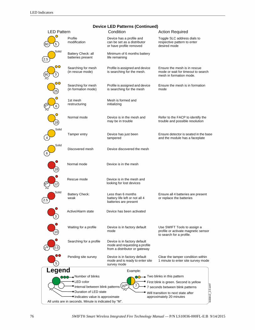
76 SWIFT® Smart Wireless Integrated Fire Technology Manual — P/N LS10036-000FL-E:B 9/14/2015
LED Indicators
LED Pattern Condition Action Required
LegendNumber of blinks
LED color
Interval between blink patterns
Duration of LED state
Indicates value is approximate
Two blinks in this pattern
First blink is green. Second is yellow
7 seconds between blink patterns
Will transition to next state after approximately 20 minutes
Example:
All units are in seconds. Minute is indicated by “M”. ledd
ev2
_2.
0.w
mf
720M
Device LED Patterns (Continued)
Battery Check: all batteries present
Searching for mesh (in rescue mode)
Profile modification
1st mesh restructuring
Normal mode
Searching for mesh (in formation mode)
Minimum of 6 months battery life remaining
Device has a profile and can be set as a distributor or have profile removed
Mesh is formed and initializing
Device is in the mesh and may be in trouble
Profile is assigned and device is searching for the mesh
Profile is assigned and device is searching for the mesh.
Tamper entry Device has just been tampered
Ensure the mesh is in rescue mode or wait for timeout to search mesh in formation mode.
Discovered mesh Device discovered the mesh
60
Solid
2.5
Toggle SLC address dials to respective pattern to enter desired mode
90 3
Ensure the mesh is in formation mode
25
65M
Refer to the FACP to identify the trouble and possible resolution18
4Ensure detector is seated in the base and the module has a faceplate
Solid
6
5
Solid
Waiting for a profile
Searching for a profile
Pending site survey
Active/Alarm state
Battery Check: weak
Device is in factory default mode
Device is in factory default mode and requesting a profile from a distributor or gateway
Device is in factory default mode and is ready to enter site survey mode
Less than 6 months battery life left or not all 4 batteries are present
Device has been activated
Use SWIFT Tools to assign a profile or activate magnetic sensor to search for a profile.
Ensure all 4 batteries are present or replace the batteries
Clear the tamper condition within 1 minute to enter site survey mode
10
5
Solid
2.5
3
0.51M
18
125M
Normal mode Device is in the mesh
Rescue mode Device is in the mesh and looking for lost devices

SWIFT® Smart Wireless Integrated Fire Technology Manual — P/N LS10036-000FL-E:B 9/14/2015 77
Appendix E: Firmware Upgrade/Downgrade Instructions
E.1 W-USB Adapter Upgrade ProcedureThe following procedure provides firmware upgrade instructions for the W-USB adapter. Please ensure the last version of SWIFT Tools is installed. SWIFT Tools and firmware can be downloaded from www.firelite.com. There are multiple .bin files with the zip file. Save the files to a folder.
1. Insert the W-USB adapter into the PC.
2. Launch SWIFT Tools and navigate to the home screen and select either Site Survey, Create Mesh Network, or Diagnostics.
3. SWIFT Tools will detect the connected USB adapter and will show an incompatibility message. Click on the OK button to dismiss the message.
4. Click on the Extras icon and navigate to Extras > Firmware Update > USB Adapter.
5. Click Browse and navigate to the folder with the saved firmware. Select the file named “USBAdaptorVx.xxx.bin”.
6. Click Update. The progress status box will show “Updating,” followed by “Updated”.
7. Once the firmware update process completes SWIFT tools displays a message indicating that the W-USB adapter has been successfully upgraded.
E.2 Gateway Firmware Upgrade/Downgrade ProcedureThe following procedure provides firmware upgrade and download instructions for the gateway. Please ensure the last version of SWIFT Tools is installed. SWIFT Tools and firmware can be downloaded from www.firelite.com. There are multiple .bin files with the zip file. Save the files to a folder.
1. Launch SWIFT Tools and navigate to the home screen and select either Site Survey, Create Mesh Network, or Diagnostics.
2. Ensure gateway is in range of W-USB adapter and the PC running SWIFT Tools.
3. Click on the Extras icon and navigate to Extras > Firmware Update > Wireless Devices.
4. Go to the Gateway area of the upgrade.
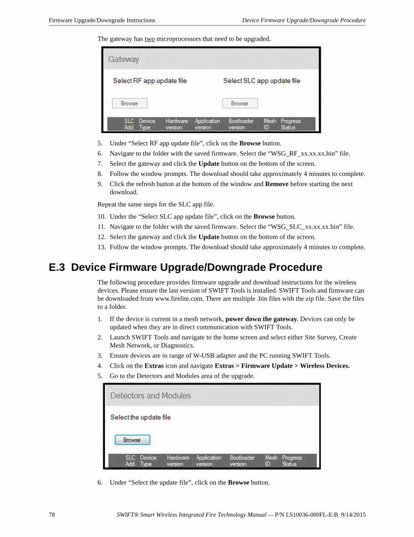
78 SWIFT® Smart Wireless Integrated Fire Technology Manual — P/N LS10036-000FL-E:B 9/14/2015
Firmware Upgrade/Downgrade Instructions Device Firmware Upgrade/Downgrade Procedure
The gateway has two microprocessors that need to be upgraded.
5. Under “Select RF app update file”, click on the Browse button.
6. Navigate to the folder with the saved firmware. Select the “WSG_RF_xx.xx.xx.bin” file.
7. Select the gateway and click the Update button on the bottom of the screen.
8. Follow the window prompts. The download should take approximately 4 minutes to complete.
9. Click the refresh button at the bottom of the window and Remove before starting the next download.
Repeat the same steps for the SLC app file.
10. Under the “Select SLC app update file”, click on the Browse button.
11. Navigate to the folder with the saved firmware. Select the “WSG_SLC_xx.xx.xx.bin” file.
12. Select the gateway and click the Update button on the bottom of the screen.
13. Follow the window prompts. The download should take approximately 4 minutes to complete.
E.3 Device Firmware Upgrade/Downgrade ProcedureThe following procedure provides firmware upgrade and download instructions for the wireless devices. Please ensure the last version of SWIFT Tools is installed. SWIFT Tools and firmware can be downloaded from www.firelite.com. There are multiple .bin files with the zip file. Save the files to a folder.
1. If the device is current in a mesh network, power down the gateway. Devices can only be updated when they are in direct communication with SWIFT Tools.
2. Launch SWIFT Tools and navigate to the home screen and select either Site Survey, Create Mesh Network, or Diagnostics.
3. Ensure devices are in range of W-USB adapter and the PC running SWIFT Tools.
4. Click on the Extras icon and navigate Extras > Firmware Update > Wireless Devices.
5. Go to the Detectors and Modules area of the upgrade.
6. Under “Select the update file”, click on the Browse button.
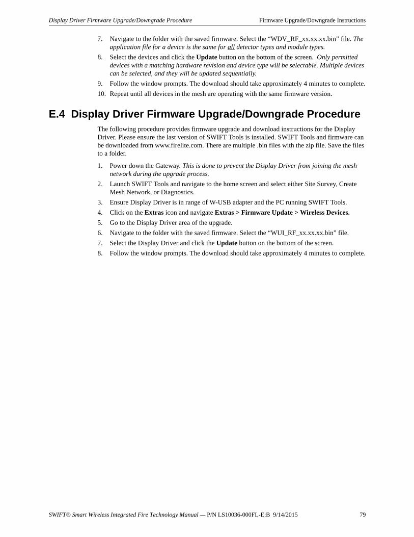
SWIFT® Smart Wireless Integrated Fire Technology Manual — P/N LS10036-000FL-E:B 9/14/2015 79
Display Driver Firmware Upgrade/Downgrade Procedure Firmware Upgrade/Downgrade Instructions
7. Navigate to the folder with the saved firmware. Select the “WDV_RF_xx.xx.xx.bin” file. The application file for a device is the same for all detector types and module types.
8. Select the devices and click the Update button on the bottom of the screen. Only permitted devices with a matching hardware revision and device type will be selectable. Multiple devices can be selected, and they will be updated sequentially.
9. Follow the window prompts. The download should take approximately 4 minutes to complete.
10. Repeat until all devices in the mesh are operating with the same firmware version.
E.4 Display Driver Firmware Upgrade/Downgrade ProcedureThe following procedure provides firmware upgrade and download instructions for the Display Driver. Please ensure the last version of SWIFT Tools is installed. SWIFT Tools and firmware can be downloaded from www.firelite.com. There are multiple .bin files with the zip file. Save the files to a folder.
1. Power down the Gateway. This is done to prevent the Display Driver from joining the mesh network during the upgrade process.
2. Launch SWIFT Tools and navigate to the home screen and select either Site Survey, Create Mesh Network, or Diagnostics.
3. Ensure Display Driver is in range of W-USB adapter and the PC running SWIFT Tools.
4. Click on the Extras icon and navigate Extras > Firmware Update > Wireless Devices.
5. Go to the Display Driver area of the upgrade.
6. Navigate to the folder with the saved firmware. Select the “WUI_RF_xx.xx.xx.bin” file.
7. Select the Display Driver and click the Update button on the bottom of the screen.
8. Follow the window prompts. The download should take approximately 4 minutes to complete.

80 SWIFT® Smart Wireless Integrated Fire Technology Manual — P/N LS10036-000FL-E:B 9/14/2015
Index
Aabbreviations 10additional references 9address 22ANN-80-W 38, 41
audible indicators 42buttons 41capacity exceeded 43clearing messages 43degraded connection 43duplicate address 42event messaging 42key bus trouble 43low battery 42maximum gateways 43mesh formation 42system initialization trouble 43tamper event 43visual indicators 41weak link 43
assign profile 36, 46, 52assumed knowledge 9attributes 70audible indicators 42
Bbootloader 25, 39, 52buttons 41
ANN-80-W 41
Ccapacity exceeded 43Class A compliance 69Class A trouble 43clearing messages 43collapse network command 27configuration 17, 35
ANN-80-W 38configure profile 24, 39CR123A batteries 45create profile 17creating jobsite 60
Ddefault 37, 39degraded connection 43detector
assign profile 46transfer profile 47
deviceattributes 70
bootloader 52distributor 52factory default 51initial mesh restructuring mode 52LED indicators 52mesh formation 52mesh participant 52network snapshots 69network statistics 69normal mode 52profile assigned 52rescue mode 52site survey 51
device operations 51device spacing 62devices 45
Class A compliance 69configuration and programming 46installing 46orphan 69parent-child 69
disable trouble reporting 26display 39display driver
specifications 32distributor 52distributor mode 49dongle 54duplicate address 42
Eevent 39event messaging 42existing profile 18
Ffactory default 24, 37, 39, 50, 51
Ggateway 11
bootloader 25collapse network 27configuration 17create mesh network 18description 11disable trouble reporting 26existing profile 18factory default 24initial mesh restructuring 24LED indicators 13lock/unlock 25

SWIFT® Smart Wireless Integrated Fire Technology Manual — P/N LS10036-000FL-E:B 9/14/2015 81
Index H–R
mesh formation 21, 24mesh restructuring 25mounting 13new profile 17normal mode 25password reset 26power 16profile configure 24profile distribution 21programming 17remove profile 18rescue mode 25restrictions 29RF interference 30silence network 28SLC configuration 22SLC connections 15specifications 12start-up 23weak link trouble 26wiring 15
GFANN-80 41visual indicators 41
Hheat detector 45
Iinitial mesh restructuring 24initial mesh restructuring mode 52installing devices 46interference 30isolator modules 16
Jjobsite
new 60open 61
jumper 14
Kkey bus trouble 43
Llatching 22LED indicators 13, 18, 19, 33, 36, 52link quality test 62
procedure 62requirements 62
lock 25low battery 42
Mmagnetic sensor 12, 18, 19, 22, 33, 36, 49magnetic sensors 33maximum gateways 43mesh formation 19, 21, 24, 37, 42, 49, 52mesh formation mode 40mesh network 18, 22, 23mesh participant 52mesh restructuring 24, 25mode
mesh formation 40normal 40rescue 40
modes of operation 23, 51module
assigning profiles 46batteries 45
module configuration 46module installation 46monitor module 45mounting 13
Nnetwork installation restrictions 29network limit 29network snapshots 69network statistics 69network topology 69normal mode 25, 40, 52
Oopening jobsite 61operations 23, 39
ANN-80 40orphan devices 69overlapping networks 29
Pparent-child devices 69password reset 26profile
assigned 52assigning 36configure 24create new 17remove 20, 50removing 18
profile configured 39profile distribution 21programming 17pull station 45
Rrelated documents 9

82 SWIFT® Smart Wireless Integrated Fire Technology Manual — P/N LS10036-000FL-E:B 9/14/2015
S–W Index
remove profile 18, 20, 50repeater 43rescue mode 25, 40, 52restrictions 29
installation 29RF interference 30RF scan test 64
status 64RF spectrum 29rotary switches 50
Ssensor
magnetic 19silence network command 28site survey 51, 62SLC configuration 22SLC connections 15SLC operation 40smoke detector 45specifications 12, 32, 55spectrum 30
RF 29spread 30
spread spectrum 30start-up 23supervisory event 32SWIFT Tools 59, 68system initialization trouble 43
Ttamper 22tamper event 43testing 68transfer profile 47transmission 24trouble 43trouble condition 25, 26trouble event 31trouble reporting
disable 26troubleshooting 66
Uunlock 25USB adapter 54
specifications 55
Vvisual indicators 41
Wwalkie talkie mode 30W-DIS-D 31
operations 39specifications 32
weak linktrouble reporting 26
weak link trouble 43W-GATE 11
specifications 12wireless devices 45wireless display driver 31wireless gateway 11wiring 15
Manufacturer Warranties and Limitation of LiabilityManufacturer Warranties. Subject to the limitations set forth herein,Manufacturer warrants that the Products manufactured by it in itsNorthford, Connecticut facility and sold by it to its authorizedDistributors shall be free, under normal use and service, from defectsin material and workmanship for a period of thirty six months (36)months from the date of manufacture (effective Jan. 1, 2009). TheProducts manufactured and sold by Manufacturer are date stamped atthe time of production. Manufacturer does not warrant Products thatare not manufactured by it in its Northford, Connecticut facility butassigns to its Distributor, to the extent possible, any warranty offeredby the manufacturer of such product. This warranty shall be void if aProduct is altered, serviced or repaired by anyone other thanManufacturer or its authorized Distributors. This warranty shall alsobe void if there is a failure to maintain the Products and the systems inwhich they operate in proper working conditions.
MANUFACTURER MAKES NO FURTHER WARRANTIES, ANDDISCLAIMS ANY AND ALL OTHER WARRANTIES, EITHEREXPRESSED OR IMPLIED, WITH RESPECT TO THE PRODUCTS,TRADEMARKS, PROGRAMS AND SERVICES RENDERED BYMANUFACTURER INCLUDING WITHOUT LIMITATION,INFRINGEMENT, TITLE, MERCHANTABILITY, OR FITNESS FORANY PARTICULAR PURPOSE. MANUFACTURER SHALL NOT BELIABLE FOR ANY PERSONAL INJURY OR DEATH WHICH MAYARISE IN THE COURSE OF, OR AS A RESULT OF, PERSONAL,COMMERCIAL OR INDUSTRIAL USES OF ITS PRODUCTS.
This document constitutes the only warranty made by Manufacturerwith respect to its products and replaces all previous warranties and isthe only warranty made by Manufacturer. No increase or alteration,written or verbal, of the obligation of this warranty is authorized.Manufacturer does not represent that its products will prevent any lossby fire or otherwise.
Warranty Claims. Manufacturer shall replace or repair, atManufacturer's discretion, each part returned by its authorizedDistributor and acknowledged by Manufacturer to be defective,provided that such part shall have been returned to Manufacturer withall charges prepaid and the authorized Distributor has completedManufacturer's Return Material Authorization form. The replacementpart shall come from Manufacturer's stock and may be new orrefurbished. THE FOREGOING IS DISTRIBUTOR'S SOLE ANDEXCLUSIVE REMEDY IN THE EVENT OF A WARRANTY CLAIM.
Warn-HL-08-2009.fm
SWIFT® Smart Wireless Integrated Fire Technology Manual — P/N LS10036-000FL-E:B 9/14/2015 83

World Headquarters1 Firelite Place
Northford, CT 06472-1653 USA203-484-7161
fax 203-484-7118
www.firelite.com