Embed Size (px)
Citation preview
The�results�in�this�report�apply�only�to�the�specimen�that�was�tested.�NRC�does�not�represent�that�the�results�in�this�report�apply�to�any�other�specimen.�B3484.5� Page�1�of�4� �
Client:� Skyfold�Custom�Powerlift�Partitions,�Railtech�Ltd.�325�Lee�Ave,�Baie�D'urfe�Montreal,�Quebec����H9X�3S3�
Specimen:� Skyfold�Classic�“4E”�
Specimen�ID:� B3484�32W�
Construction�Dates:� August�19,�2010�to�August�20,�2010�
�
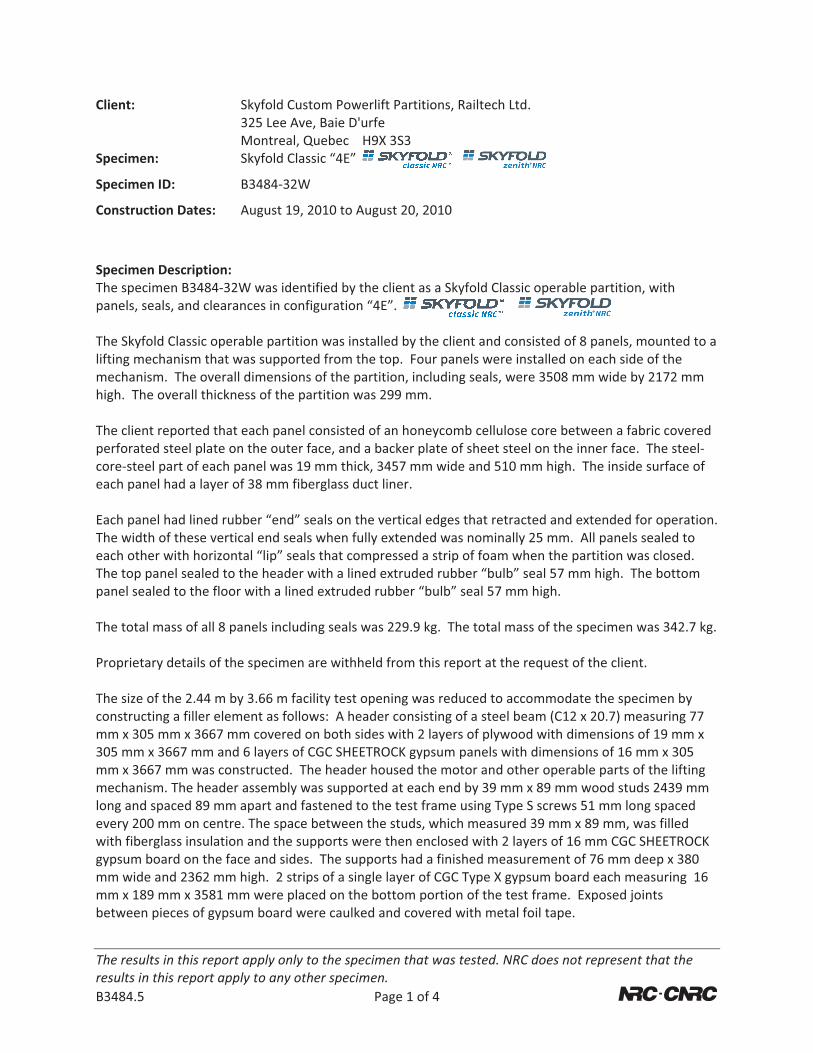
Specimen�Description:�The�specimen�B3484�32W�was�identified�by�the�client�as�a�Skyfold�Classic�operable�partition,�with�panels,�seals,�and�clearances�in�configuration�“4E”.��The�Skyfold�Classic�operable�partition�was�installed�by�the�client�and�consisted�of�8�panels,�mounted�to�a�lifting�mechanism�that�was�supported�from�the�top.��Four�panels�were�installed�on�each�side�of�the�mechanism.��The�overall�dimensions�of�the�partition,�including�seals,�were�3508�mm�wide�by�2172�mm�high.��The�overall�thickness�of�the�partition�was�299�mm.��The�client�reported�that�each�panel�consisted�of�an�honeycomb�cellulose�core�between�a�fabric�covered�perforated�steel�plate�on�the�outer�face,�and�a�backer�plate�of�sheet�steel�on�the�inner�face.��The�steel�core�steel�part�of�each�panel�was�19�mm�thick,�3457�mm�wide�and�510�mm�high.��The�inside�surface�of�each�panel�had�a�layer�of�38�mm�fiberglass�duct�liner.��Each�panel�had�lined�rubber�“end”�seals�on�the�vertical�edges�that�retracted�and�extended�for�operation.��The�width�of�these�vertical�end�seals�when�fully�extended�was�nominally�25�mm.��All�panels�sealed�to�each�other�with�horizontal�“lip”�seals�that�compressed�a�strip�of�foam�when�the�partition�was�closed.��The�top�panel�sealed�to�the�header�with�a�lined�extruded�rubber�“bulb”�seal�57�mm�high.��The�bottom�panel�sealed�to�the�floor�with�a�lined�extruded�rubber�“bulb”�seal�57�mm�high.��The�total�mass�of�all�8�panels�including�seals�was�229.9�kg.��The�total�mass�of�the�specimen�was�342.7�kg.��Proprietary�details�of�the�specimen�are�withheld�from�this�report�at�the�request�of�the�client.��The�size�of�the�2.44�m�by�3.66�m�facility�test�opening�was�reduced�to�accommodate�the�specimen�by�constructing�a�filler�element�as�follows:��A�header�consisting�of�a�steel�beam�(C12�x�20.7)�measuring�77�mm�x�305�mm�x�3667�mm�covered�on�both�sides�with�2�layers�of�plywood�with�dimensions�of�19�mm�x�305�mm�x�3667�mm�and�6�layers�of�CGC�SHEETROCK�gypsum�panels�with�dimensions�of�16�mm�x�305�mm�x�3667�mm�was�constructed.��The�header�housed�the�motor�and�other�operable�parts�of�the�lifting�mechanism.�The�header�assembly�was�supported�at�each�end�by�39�mm�x�89�mm�wood�studs�2439�mm�long�and�spaced�89�mm�apart�and�fastened�to�the�test�frame�using�Type�S�screws�51�mm�long�spaced�every�200�mm�on�centre.�The�space�between�the�studs,�which�measured�39�mm�x�89�mm,�was�filled�with�fiberglass�insulation�and�the�supports�were�then�enclosed�with�2�layers�of�16�mm�CGC�SHEETROCK�gypsum�board�on�the�face�and�sides.��The�supports�had�a�finished�measurement�of�76�mm�deep�x�380�mm�wide�and�2362�mm�high.��2�strips�of�a�single�layer�of�CGC�Type�X�gypsum�board�each�measuring��16�mm�x�189�mm�x�3581�mm�were�placed�on�the�bottom�portion�of�the�test�frame.��Exposed�joints�between�pieces�of�gypsum�board�were�caulked�and�covered�with�metal�foil�tape.��
The�results�in�this�report�apply�only�to�the�specimen�that�was�tested.�NRC�does�not�represent�that�the�results�in�this�report�apply�to�any�other�specimen.�B3484.5� Page�2�of�4� �
Test�Specimen�Installation:��The�test�specimen�was�installed�in�the�NRC�IRC�Wall�Sound�Transmission�Facility.��The�facility�test�opening�measures�2.44�m�by�3.�66�m.��The�area�was�reduced�by�constructing�filler�elements,�as�described�above.�The�perimeter�of�the�filler�elements�was�sealed�on�both�sides�to�the�facility�test�opening�with�latex�caulk�and�covered�with�metal�foil�tape.��The�opening�in�the�filler�elements�for�the�test�specimen�measured�3508�mm�wide�by�2172�mm�high.����The�area�used�for�calculation�of�sound�absorption�was�7.66�m².��The�specimen�was�opened�and�closed�five�times�after�installation�was�completed�and�was�tested�without�further�adjustments.��
�
� �
C
S
Te
D
MH
L
F
The�resultresults�in�B3484.5�
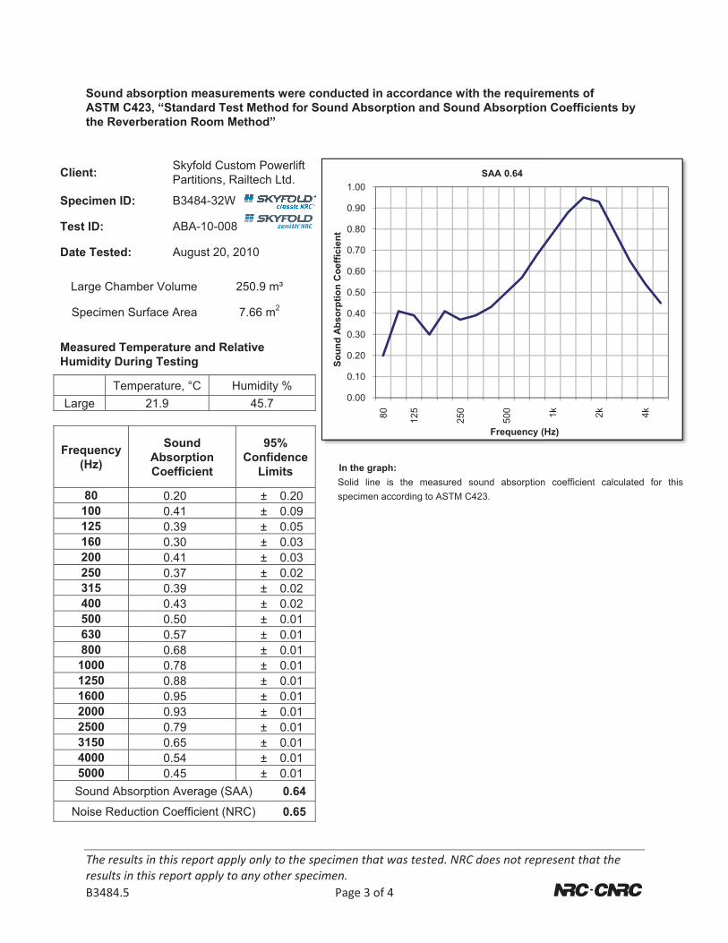
Sound abASTM C4the Reve
lient:
pecimen ID:
est ID:
Date Tested:
Large Cham
Specimen S
Measured Temumidity Duri
TemLarge
requency (Hz)
80 100 125 160 200 250 315 400 500 630 800 1000 1250 1600 2000 2500 3150 4000 5000 Sound Abso
Noise Reduc
ts�in�this�repothis�report�ap
bsorption me423, “Standarberation Ro
SkyfolPartitio
B3484
ABA-1
Augus
ber Volume
urface Area
mperature aning Testing
perature, °C21.9
SoundAbsorptioCoefficien
0.20 0.41 0.39 0.30 0.41 0.37 0.39 0.43 0.50 0.57 0.68 0.78 0.88 0.95 0.93 0.79 0.65 0.54 0.45
orption Avera
ction Coefficie
ort�apply�only�pply�to�any�ot
easurementsrd Test Meth
oom Method”
d Custom Poons, Railtech
4-32W
10-008
st 20, 2010
250.9 m
7.66 m
nd Relative
Humidit45.7
onnt
95Confi
Lim
±±±±±±±±±±±±±±±±±±±
ge (SAA)
ent (NRC)
to�the�specimther�specimen
P
s were conduhod for Soun”
owerlift Ltd.
ISs
m³
m2
y %7
5%idence mits
0.20 0.09 0.05 0.03 0.03 0.02 0.02 0.02 0.01 0.01 0.01 0.01 0.01 0.01 0.01 0.01 0.01 0.01 0.01 0.64 0.65
Soun
dAb
sorp
tion
Coe
ffici
ent
men�that�was�n.�Page�3�of�4
ucted in accod Absorptio
In the graph: Solid line is thespecimen accord
0.00
0.10
0.20
0.30
0.40
0.50
0.60
0.70
0.80
0.90
1.00
80
Soun
dAb
sorp
tion
Coe
ffici
ent
tested.�NRC�d
ordance withn and Sound
e measured soding to ASTM C4
125
250
does�not�repr
h the required Absorption
ound absorption23.
500
Frequency (
SAA 0.64
resent�that�th
ments of n Coefficients
n coefficient cal
1k 2k
Hz)
he�
�
s by
lculated for this
4k
s
APPENDIX: Sound Absorption M-27 Facility
National�Research�Council�Canada��Institute�for�Research�in�Construction�Acoustics�Laboratory�1200�Montreal�Road,�Ottawa,�Ontario�K1A�0R6�Tel: 613-993-2305 Fax: 613-954-1495
The�results�in�this�report�apply�only�to�the�specimen�that�was�tested.�NRC�does�not�represent�that�the�results�in�this�report�apply�to�any�other�specimen.�B3484.5� Page�4�of�4� �
Facility and Procedure: The facility for absorption testing has a reverberation room with nominal volume of 250 m3. The room has four loudspeakers driven by separate amplifiers and noise sources controlled by a computer. To increase the randomness of the sound field, there are fixed and moving diffusing panels in the room. In this room, a calibrated Bruel & Kjaer type 4166 microphone with preamp is moved under computer control to nine repeatable positions, and measurements of sound decays are made. Sound absorption measurements are conducted in accordance with the requirements of ASTM C423-02a, “Standard Test Method for Sound Absorption and Sound Absorption Coefficients by the Reverberation Room Method”. Mean empty room reverberation times are obtained by averaging the measurements of ten decays at each of nine microphone positions. Similarly, mean reverberation times are obtained with the specimen in the chamber, at 9 microphone positions for each test specimen position; the latter depends on the specimen mounting (see below). The mean reverberation times are then used to calculate the absorption coefficient in each one-third-octave band. Specimen Mounting: Standard mounting conditions for absorption testing conform to ASTM C423-02a and ASTM E795-00 “Standard Practices for Mounting Test Specimens During Sound Absorption Tests.” Mountings normally used at this laboratory include:
� A Mounting—The test specimen is laid directly on the floor, with its perimeter edges covered by a wood frame that is sealed to the floor. Measurements are made for one standard position.
� E400 Mounting—The test specimen is installed in a standard frame (area 2.74 m x 2.44 m) that supports the specimen 400 mm above the chamber floor. Measurements are made for two standard positions, with the frame sealed to the floor.
� Office screen—This special case is referred to as “Type K Mounting” in ASTM E795-00. Measurements are made for three standard positions, with the test specimen standing on the floor.
Sound Absorption Coefficients: Sound absorption for a specimen is measured in square metres. “1 m2 of absorption” may be thought of as one square metre of perfect absorber. Sound absorption coefficients are derived by dividing the sound absorption of the complete specimen (metric sabins) at each frequency by the total surface area of a specimen in square metres. Diffraction effects usually cause the effective area of a specimen to be greater than its geometrical area thereby increasing the measured absorption coefficient. When the coefficients are large, the measured values may exceed unity, but no adjustments to the measured coefficients are made. Sound Absorption Average (SAA), and Noise Reduction Coefficient (NRC) are single number ratings calculated from measured sound absorption coefficients, as specified in ASTM C423-02a. SAA is the average of the sound absorption coefficients of a material for the one-third-octave bands from 200 through 2500 Hz, inclusive, rounded to the nearest multiple of 0.01. NRC is the average of the sound absorption coefficients of a material for 250, 500, 1000 and 2000 Hz rounded to the nearest multiple of 0.05. The higher the SAA or NRC value, the greater the average sound absorption. Confidence Limits and Significance of Test Results: Acoustical measurement in rooms is a sampling process and as such has associated with it a degree of uncertainty. By using enough microphone and loudspeaker positions, the uncertainty can be reduced and upper and lower limits assigned to the probable error in the measurement. These limits are called 95% confidence limits. They are calculated for each test according to the procedures in ASTM C423-02a and must be less than upper limits given in the standards. These confidence limits do not relate directly to the variation expected when a nominally identical specimen is built, installed and tested (repeatability). Nor do they relate to the differences expected when nominally identical specimens are tested in different laboratories (reproducibility). Standard test procedures require measurements in 1/3-octave bands over a specified frequency range (100 to 5000 Hz for ASTM C423-02a). Within this range, reproducibility has been assessed by inter-laboratory round robin studies. The standards recommend making measurements and reporting results over a larger frequency range, and this report presents such results, which may be useful for expert evaluation of the specimen performance.�