Embed Size (px)
Citation preview
IDEAL 4215
GB Operating InstructionsGuillotines
- 6 -
IDEAL 4215
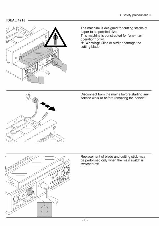
The machine is designed for cutting stacks ofpaper to a specified size.This machine is constructed for "one-manoperation" only!
Warning! Clips or similar damage thecutting blade.
Disconnect from the mains before starting anyservice work or before removing the panels!
Replacement of blade and cutting stick maybe performed only when the main switch isswitched off!
• Safety precautions •
- 7 -
• Safety precautions •
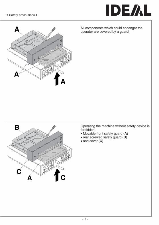
All components which could endanger theoperator are covered by a guard!
Operating the machine without safety device isforbidden!• Movable front safety guard (A)• rear screwed safety guard (B)• and cover (C)

- 8 -
IDEAL 4215
The dangerous cutting movement issafeguarded by a movable guard (A), rearscrewed safety guard (B) and a safetytwo-handed control system! (C)
Before working with the machine and afterevery blade replacement the automatic cut-offfunction of safety guard (A),(correct if distancebetween cover and table is < 15 mm) mainswitch (B) and control panel (C) must bechecked.
• Safety precautions •
- 9 -
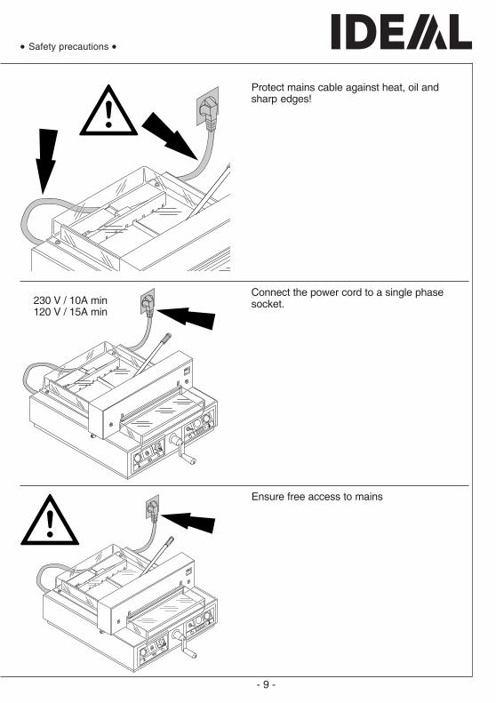
230 V / 10A min120 V / 15A min
Protect mains cable against heat, oil andsharp edges!
Connect the power cord to a single phasesocket.
Ensure free access to mains
• Safety precautions •

- 10 -
IDEAL 4215
When not in use for a longer period switch off.(Main switch to "0").
• Safety precautions •
Clamping BladeOK
OK
Danger!Do not turn main switch to position "0"whilstblade is moving upwards or downwards!Risk of injury!
Danger! Blade must always be coveredby the pressing bar.
- 11 -
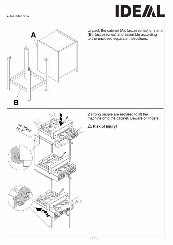
Unpack the cabinet (A), (accessories) or stand(B), (accessories) and assemble accordingto the enclosed separate instructions.
2 strong people are required to lift themachine onto the cabinet. Beware of fingers!
Risk of injury!
• Installation •
- 12 -
IDEAL 4215
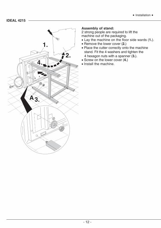
Assembly of stand:2 strong people are required to lift themachine out of the packaging.• Lay the machine on the floor side wards (1.).• Remove the lower cover (2.)• Place the cutter correctly onto the machine
stand. Fit the 4 washers and tighten the4 hexagon nuts with a spanner (3.).
• Screw on the lower cover (4.)• Install the machine.
• Installation •

- 13 -
Plug into socket.
• Installation •
- 14 -
IDEAL 4215
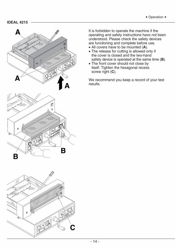
It is forbidden to operate the machine if theoperating and safety instructions have not beenunderstood. Please check the safety devicesare functioning and complete before use.• All covers have to be mounted (A).• The release for cutting is allowed only if
the cover is closed and the two-handsafety device is operated at the same time (B).
• The front cover should not close byitself. Tighten the hexagonal recessscrew right (C).
We recommend you keep a record of your testresults.
• Operation •
- 15 -
C
B
A
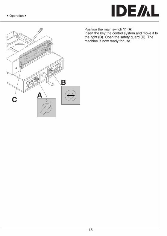
Position the main switch "I" (A)Insert the key the control system and move it tothe right (B). Open the safety guard (C). Themachine is now ready for use.
• Operation •
- 16 -
IDEAL 4215
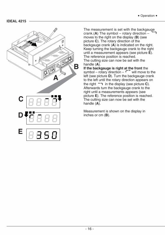
The measurement is set with the backgaugecrank.(A) The symbol – rotary direction –moves to the right on the display (B) (seepicture C). The rotary direction of thebackgauge crank (A) is indicated on the right.Keep turning the backgauge crank to the rightuntil a measurement appears (see picture E).The reference position is reached.The cutting size can now be set with thehandle (A).If the backgauge is right at the front thesymbol – rotary direction – will move to theleft (see picture D). Turn the backgauge crankto the left until the rotary direction appears onthe right in the display (see picture C).Afterwards turn the backgauge crank to theright until a measurements appears (seepicture E). The reference position is reached.The cutting size can now be set with thehandle (A).
Measurement is shown on the display ininches or cm (B).
• Operation •
- 17 -
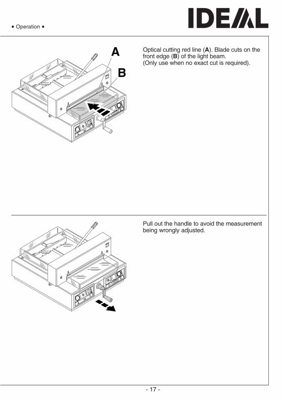
Optical cutting red line (A). Blade cuts on thefront edge (B) of the light beam.(Only use when no exact cut is required).
Pull out the handle to avoid the measurementbeing wrongly adjusted.
• Operation •

- 18 -
IDEAL 4215
Position the paper on the backgauge (A) andthe side lay (B). To move paper stacks,please use the paper knock-up block (C).Run backgauge to the front for turning thepaper stack.
Close the safety guard.
• Operation •
- 19 -
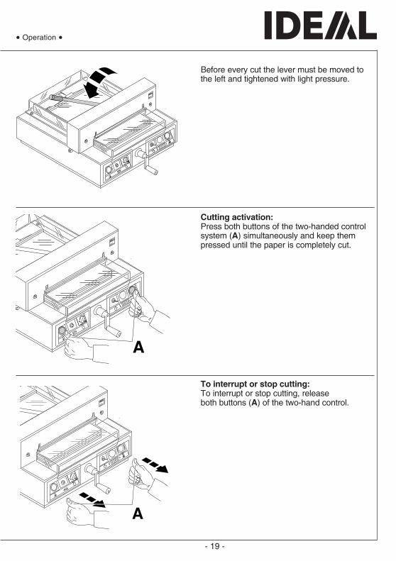
Before every cut the lever must be moved tothe left and tightened with light pressure.
Cutting activation:Press both buttons of the two-handed controlsystem (A) simultaneously and keep thempressed until the paper is completely cut.
To interrupt or stop cutting:To interrupt or stop cutting, releaseboth buttons (A) of the two-hand control.
• Operation •
- 20 -
IDEAL 4215
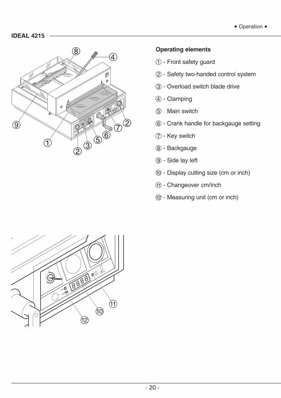
Operating elements
A - Front safety guard
B - Safety two-handed control system
C - Overload switch blade drive
D - Clamping
E - Main switch
F - Crank handle for backgauge setting
G - Key switch
H - Backgauge
I - Side lay left
J - Display cutting size (cm or inch)
K - Changeover cm/inch
L - Measuring unit (cm or inch)
• Operation •
- 21 -
• Operation •
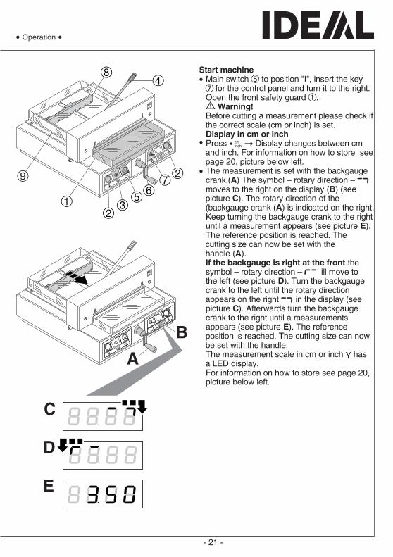
Start machine• Main switch E to position "I", insert the key
G for the control panel and turn it to the right.Open the front safety guard A.
Warning!Before cutting a measurement please check ifthe correct scale (cm or inch) is set.Display in cm or inch
• Press q Display changes between cmand inch. For information on how to store seepage 20, picture below left.
• The measurement is set with the backgaugecrank.(A) The symbol – rotary direction – moves to the right on the display (B) (seepicture C). The rotary direction of the(backgauge crank (A) is indicated on the right.Keep turning the backgauge crank to the rightuntil a measurement appears (see picture E).The reference position is reached. Thecutting size can now be set with thehandle (A).If the backgauge is right at the front thesymbol – rotary direction – ill move tothe left (see picture D). Turn the backgaugecrank to the left until the rotary directionappears on the right in the display (seepicture C). Afterwards turn the backgaugecrank to the right until a measurementsappears (see picture E). The referenceposition is reached. The cutting size can nowbe set with the handle.The measurement scale in cm or inch Y hasa LED display.For information on how to store see page 20,picture below left.
- 22 -
IDEAL 4215
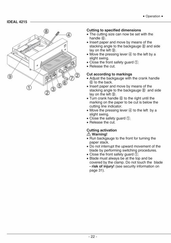
Cutting to specified dimensions• The cutting size can now be set with the
handle F.• Insert paper and move by means of the
stacking angle to the backgauge H and sidelay on the left I.
• Move the pressing lever D to the left by aslight swing.
• Close the front safety guard A.• Release the cut.
Cut according to markings• Adjust the backgauge with the crank handle
F to the back.• Insert paper and move by means of the
stacking angle to the backgauge H and sidelay on the left I.
• Turn crank handle F to the right until themarking on the paper to be cut is below thecutting line indicator.
• Move the pressing lever D to the left by aslight swing.
• Close the safety guard A.• Release the cut.
Cutting activation Warning!
• Run backgauge to the front for turning thepaper stack.
• Do not interrupt the upward movement of theblade by performing switching procedures.
• Close the front safety guard A.• Blade must always be at the top and be
covered by the clamp. Do not touch the blade- risk of injury! (see security information onpage 31).
• Operation •
- 23 -
• Blade and cutting stick replacement •
If the cutting quality decreases:• Check the cutting depth (see page 31).• Check the cutting stick (see page 24).• Replace or grind the blade
(see page 23 - 31).The blade cannot be ground if the bladeheight is less than 35 mm/1,38 inches. Anew blade must be used.Purchase the new blade from Krug &Priester, D -72336 Balingen only.The blade may only be ground by aqualified workshop or from themanufacturer Krug & Priester,D -72336 Balingen.
Danger! Risk of injury!The blade is extremely sharp. Do notextract or transport the blade withoutprotection. Changing the blade may only beperformed by trained staff.

- 24 -
IDEAL 4215
Turn the blade depth adjustment screw to theleft until it stops (screwdriver found intool set (A).
• Blade and cutting stick replacement •
Cutting stick replacement :• Lift the cover (1.)• Lift the cutting stick by hand and pull it out.(2.).• If needed the cutting stick can be turned or
exchanged. (The cutting stick can be usedeight times). (3.).
After exchanging the cutting stick close theclamp by moving the clamp lever to the left(4).
- 25 -
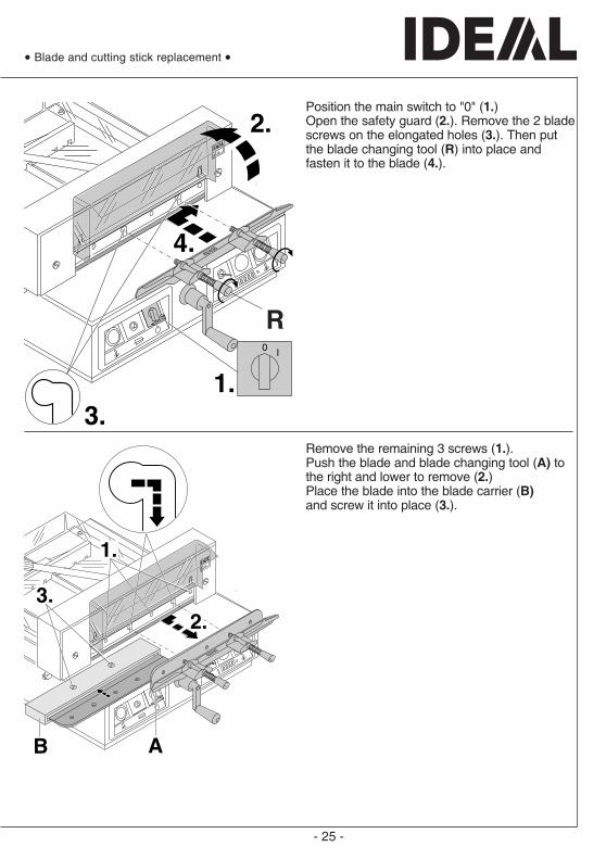
Remove the remaining 3 screws (1.).Push the blade and blade changing tool (A) tothe right and lower to remove (2.)Place the blade into the blade carrier (B)and screw it into place (3.).
• Blade and cutting stick replacement •
Position the main switch to "0" (1.)Open the safety guard (2.). Remove the 2 bladescrews on the elongated holes (3.). Then putthe blade changing tool (R) into place andfasten it to the blade (4.).
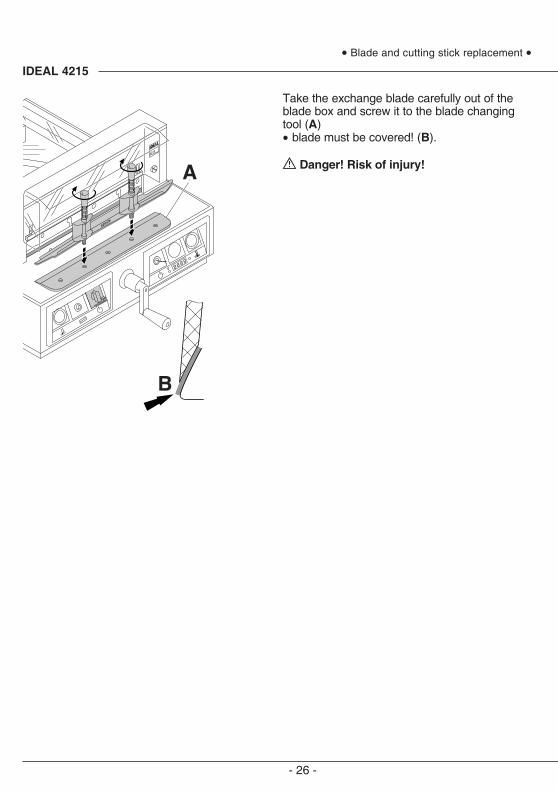
- 26 -
IDEAL 4215
Take the exchange blade carefully out of theblade box and screw it to the blade changingtool (A)• blade must be covered! (B).
Danger! Risk of injury!
• Blade and cutting stick replacement •
- 27 -
• Blade and cutting stick replacement •
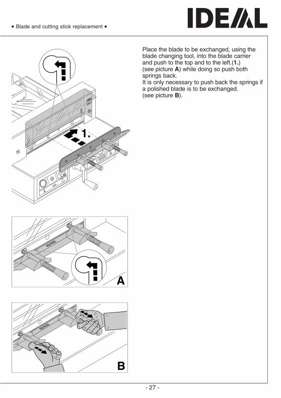
Place the blade to be exchanged, using theblade changing tool, into the blade carrierand push to the top and to the left.(1.)(see picture A) while doing so push bothsprings back.It is only necessary to push back the springs ifa polished blade is to be exchanged.(see picture B).
- 28 -
IDEAL 4215
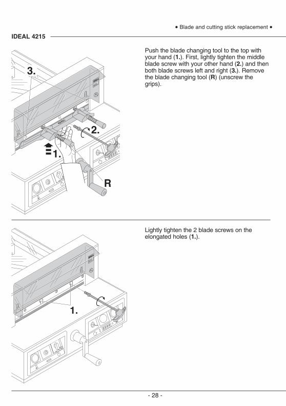
Push the blade changing tool to the top withyour hand (1.). First, lightly tighten the middleblade screw with your other hand (2.) and thenboth blade screws left and right (3.). Removethe blade changing tool (R) (unscrew thegrips).
• Blade and cutting stick replacement •
Lightly tighten the 2 blade screws on theelongated holes (1.).
- 29 -
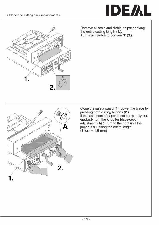
Close the safety guard (1.) Lower the blade bypressing both cutting buttons (2.)If the last sheet of paper is not completely cut,gradually turn the knob for blade-depthadjustment (A) ¼ turn to the right until thepaper is cut along the entire length.(1 turn = 1,5 mm)
• Blade and cutting stick replacement •
Remove all tools and distribute paper alongthe entire cutting length (1.).Turn main switch to position "I" (2.).
- 30 -
IDEAL 4215
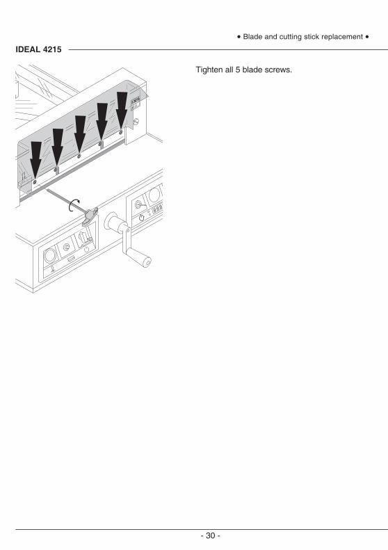
Tighten all 5 blade screws.
• Blade and cutting stick replacement •
- 31 -
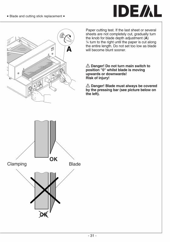
Paper cutting test. If the last sheet or severalsheets are not completely cut, gradually turnthe knob for blade depth adjustment (A)¼ turn to the right until the paper is cut alongthe entire length. Do not set too low as bladewill become blunt sooner.
Danger! Do not turn main switch toposition "0" whilst blade is movingupwards or downwards!Risk of injury!
Danger! Blade must always be coveredby the pressing bar (see picture below onthe left).
Clamping BladeOK
OK
• Blade and cutting stick replacement •
- 32 -
IDEAL 4215
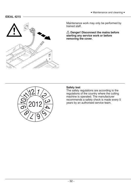
Maintenance work may only be performed bytrained staff.
Danger! Disconnect the mains beforestarting any service work or beforeremoving the cover.
• Maintenance and cleaning •
Safety testThe safety regulations are according to theregulations of the country where the cuttingmachine is operated. The manufacturerrecommends a safety check is made every 5years by an authorised service team.
- 33 -
AB
F
Nr. 9003 233
Nr. 9001 828
• Blade and cutting stick replacement •
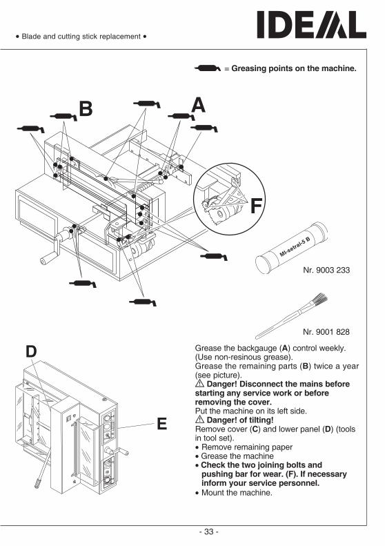
Grease the backgauge (A) control weekly.(Use non-resinous grease).Grease the remaining parts (B) twice a year(see picture).
Danger! Disconnect the mains beforestarting any service work or beforeremoving the cover.Put the machine on its left side.
Danger! of tilting!Remove cover (C) and lower panel (D) (toolsin tool set).• Remove remaining paper• Grease the machine• Check the two joining bolts and
pushing bar for wear. (F). If necessaryinform your service personnel.
• Mount the machine.
= Greasing points on the machine.
- 34 -
IDEAL 4215
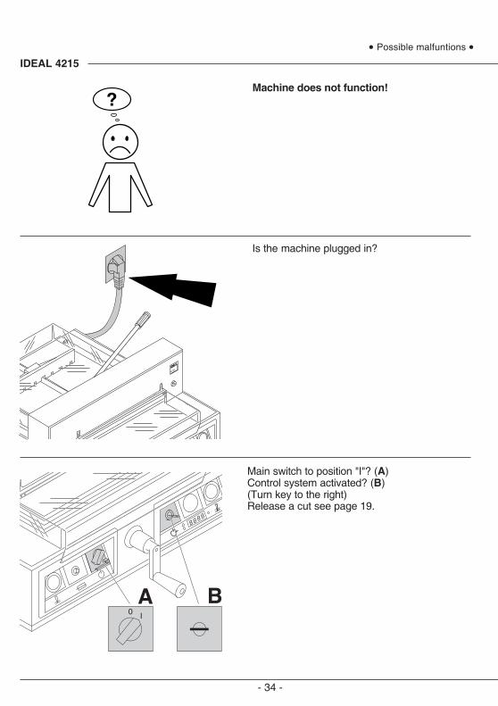
Machine does not function!
Is the machine plugged in?
Main switch to position "I"? (A)Control system activated? (B)(Turn key to the right)Release a cut see page 19.
• Possible malfuntions •
- 35 -
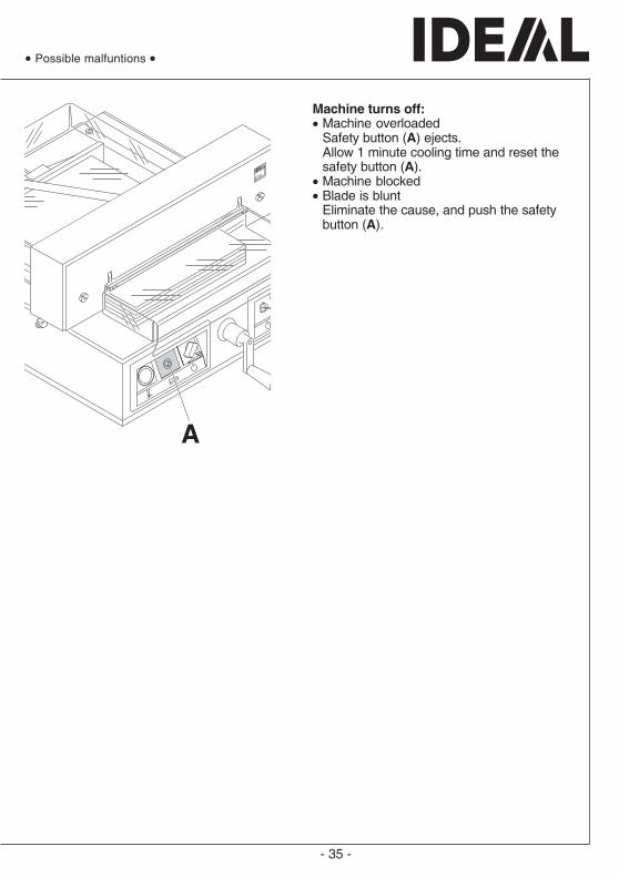
Machine turns off:• Machine overloaded
Safety button (A) ejects.Allow 1 minute cooling time and reset thesafety button (A).
• Machine blocked• Blade is blunt
Eliminate the cause, and push the safetybutton (A).
• Possible malfuntions •

- 36 -
IDEAL 4215
Does not cut through the last sheet:• Turn or turn around the cutting stick (A),
readjust the blade by means of the bladeadjusting knob (B).(See page 31).
Poor cutting quality or blade stays in thepaper stack.• change the blade (C) (see page 23 - 31).
• Possible malfuntions •
- 37 -
• Possible malfuntions •
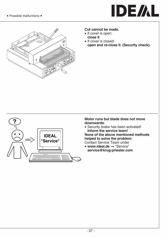
Motor runs but blade does not movedownwards.• Security brake has been activated!
Inform the service team!None of the above mentioned methodshelped to solve the problem:Contact Service Team under• www.ideal.de "Service"
Cut cannot be made.• If cover is open:
close it.• If cover is closed:
open and re-close it. (Security check).
- 38 -
IDEAL 4215• Accessories •
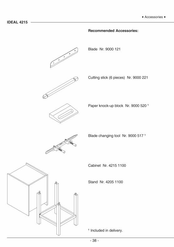
Recommended Accessories:
Blade Nr. 9000 121
Cutting stick (6 pieces) Nr. 9000 221
Paper knock-up block Nr. 9000 520 1
Blade changing tool Nr. 9000 517 1
Cabinet Nr. 4215 1100
Stand Nr. 4205 1100
1 Included in delivery.
- 39 -
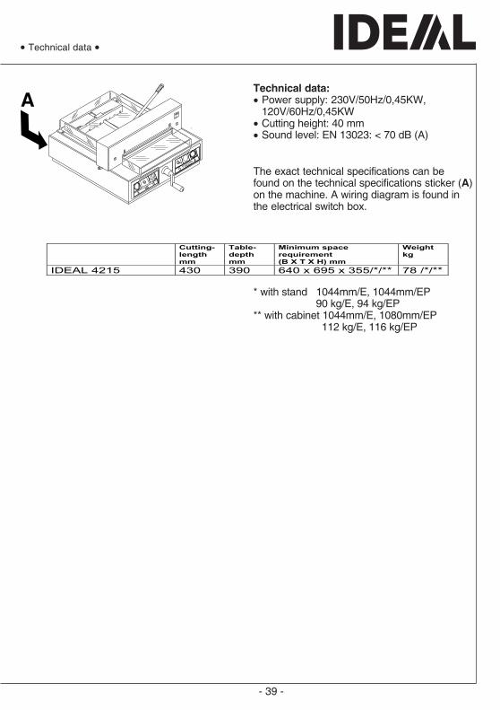
Technical data:• Power supply: 230V/50Hz/0,45KW,
120V/60Hz/0,45KW• Cutting height: 40 mm• Sound level: EN 13023: < 70 dB (A)
The exact technical specifications can befound on the technical specifications sticker (A)on the machine. A wiring diagram is found inthe electrical switch box.
• Technical data •
* with stand 1044mm/E, 1044mm/EP 90 kg/E, 94 kg/EP
** with cabinet 1044mm/E, 1080mm/EP 112 kg/E, 116 kg/EP
Cutting-
length mm
Table- depth mm
Minimum space requirement (B X T X H) mm
Weight kg
IDEAL 4215 430 390 640 x 695 x 355/*/** 78 /*/**

- 40 -
IDEAL 4215
This machine is approved by independentsafety laboratories and is in compliance with theEC-regulations 98/37/EG, 2006/95/EG and2004/108/EG.
Sound level information:The sound level is < 70 db (A) as defined byEN 13023.
Subject to alteration without notice.
• Technical data •


![Biomass Auto Guard Ado] Auto Guard Ado]](https://img.pdfslide.net/doc/110x75/577d2a201a28ab4e1ea8b9ec/biomass-auto-guard-ado-auto-guard-ado.jpg)


![Oki B410,B420,B430,B440 - ServiceMan [2008]](https://img.pdfslide.net/doc/110x75/577cc3b41a28aba71196ec38/oki-b410b420b430b440-serviceman-2008.jpg)
