Embed Size (px)
Citation preview

BA 239F/00/en/02.0452010988Valid as of software version:V 01.02.00 (amplifier)V 1.0 (communication)
prosonic MFMU 40/41/42/43with Foundation FieldbusUltrasonic Level Measurement
Operating Instructions
F
TM
TM
FMU 40
FMU 41
FMU 43
FMU 42
Prosonic M FMU 40/41/42/43 with Foundation Fieldbus
2
Short instructions
L00-FMU4xxx-05-00-00-en-001
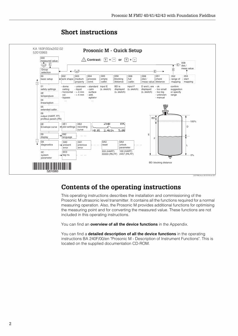
Contents of the operating instructionsThis operating instructions describes the installation and commissioning of the Prosonic M ultrasonic level transmitter. It contains all the functions required for a normal measuring operation. Also, the Prosonic M provides additional functions for optimising the measuring point and for converting the measured value. These functions are not included in this operating instructions.
You can find an overview of all the device functions in the Appendix.
You can find a detailed description of all the device functions in the operating instructions BA 240F/00/en "Prosonic M - Description of Instrument Functions". This is located on the supplied documentation CD-ROM.
E+-
+
E+-
F
L
D
E
E
E
-
… …
KA 183F/00/a2/02.0252010993
BD
… …
100%
0%
100 (HART)2457 (PA,FF)
333 (HART)33333 (PA,FF)
… …
52010993
… …
Prosonic M - Quick Setup
- domeceiling
- horizontalcyl.
- bypass…
- unknown- liquid- > 4 mm- < 4 mm
- standard- calm
surface- add.
agitator…
input E(s. sketch)
input F(s. sketch)
- ok- too small- too big- unknown- manual
displayed(s. sketch)
D and L are confirm
or specifyrange
suggestion
000measured value
Groupselection
00basic setup
01safety settings
0Csystemparameter
0EEnvelope curve
04linearisation
05extended calibr.
06output (HART, FF)profibus param.(PA)
0Adiagnostics
0A0presenterror
002tank shape
004processcond.
005emptycalibr.
006fullcalibr.
008dist./meas value
051checkdistance
003mediumproperty
052range ofmapping
053startmapping
008dist./meas value
0E1plot settings
0E2recordingcurve
0A1previouserror
0A4unlockparameter
0Etemperature
09display
092language
BD: blocking distance
0A3reset
0C0tag no.
059blockingdistance
Bdisplayed(s. sketch)
D is
Contrast: + or +
Prosonic M FMU 40/41/42/43 with Foundation Fieldbus
3
Table of contents
1 Safety instructions . . . . . . . . . . . . . . 41.1 Designated use . . . . . . . . . . . . . . . . . . . . . . . . 41.2 Installation, commissioning, operation . . . . . . 41.3 Hazardous area . . . . . . . . . . . . . . . . . . . . . . . . 41.4 Notes on safety conventions and symbols . . . 5
2 Identification . . . . . . . . . . . . . . . . . . . 62.1 Nameplate . . . . . . . . . . . . . . . . . . . . . . . . . . . . 62.2 Scope of delivery . . . . . . . . . . . . . . . . . . . . . . . 62.3 Certificates and approvals . . . . . . . . . . . . . . . . 72.4 Registered trademarks . . . . . . . . . . . . . . . . . . 7
3 Installation. . . . . . . . . . . . . . . . . . . . . 83.1 Dimensions . . . . . . . . . . . . . . . . . . . . . . . . . . . 83.2 Installation variants . . . . . . . . . . . . . . . . . . . . . 93.3 Installation conditions . . . . . . . . . . . . . . . . . . 113.4 Measuring range . . . . . . . . . . . . . . . . . . . . . . 143.5 Installation hint for FMU 40/41 . . . . . . . . . . . . 153.6 Turn housing . . . . . . . . . . . . . . . . . . . . . . . . . 163.7 Installation check . . . . . . . . . . . . . . . . . . . . . . 16
4 Wiring . . . . . . . . . . . . . . . . . . . . . . . . 174.1 Electrical connection . . . . . . . . . . . . . . . . . . . 174.2 Terminal assignment . . . . . . . . . . . . . . . . . . . 194.3 Cable specifications Foundation Fieldbus . . 194.4 Supply voltage . . . . . . . . . . . . . . . . . . . . . . . . 194.5 Recommended connection . . . . . . . . . . . . . . 204.6 Checking the connection . . . . . . . . . . . . . . . . 20
5 Operation . . . . . . . . . . . . . . . . . . . . . 215.1 Display and operating elements . . . . . . . . . . 215.2 Function codes . . . . . . . . . . . . . . . . . . . . . . . 235.3 Foundation Fieldbus interface . . . . . . . . . . . . 245.4 Operation using the on-site display VU 331 . 415.5 Lock/unlock configuration . . . . . . . . . . . . . . . 425.6 Resetting the customer parameters . . . . . . . 425.7 Resetting an interference echo suppression (tank
map) . . . . . . . . . . . . . . . . . . . . . . . . . . . . . . . . 43
6 Commissioning . . . . . . . . . . . . . . . . 446.1 Power up instrument . . . . . . . . . . . . . . . . . . . 446.2 Basic calibration . . . . . . . . . . . . . . . . . . . . . . 456.3 Envelope curve . . . . . . . . . . . . . . . . . . . . . . . 50
7 Troubleshooting . . . . . . . . . . . . . . . 537.1 System error messages . . . . . . . . . . . . . . . . . 537.2 Application errors . . . . . . . . . . . . . . . . . . . . . 55
8 Maintenance and repairs . . . . . . . . 578.1 Exterior cleaning . . . . . . . . . . . . . . . . . . . . . . 578.2 Repairs . . . . . . . . . . . . . . . . . . . . . . . . . . . . . . 57
8.3 Repairs to Ex-approved devices . . . . . . . . . . 578.4 Replacement . . . . . . . . . . . . . . . . . . . . . . . . . . 578.5 Spare parts (housing type F12) . . . . . . . . . . . 588.6 Spare parts (housing type T12) . . . . . . . . . . . 598.7 Return . . . . . . . . . . . . . . . . . . . . . . . . . . . . . . . 608.8 Disposal . . . . . . . . . . . . . . . . . . . . . . . . . . . . . 608.9 Software history . . . . . . . . . . . . . . . . . . . . . . . 608.10 Contact addresses of Endress+Hauser . . . . . 60
9 Accessories . . . . . . . . . . . . . . . . . . . . 619.1 Weather protection cover . . . . . . . . . . . . . . . . 619.2 Installation bracket for FMU 40/41 . . . . . . . . . 619.3 Adapter flange for FMU 40 / FMU 41 . . . . . . . 629.4 Cantilever . . . . . . . . . . . . . . . . . . . . . . . . . . . . 639.5 Mounting Frame for Cantilever . . . . . . . . . . . . 649.6 Wall Bracket for Cantilever . . . . . . . . . . . . . . . 649.7 Mounting bracket for FMU 43 . . . . . . . . . . . . . 659.8 Service Interface FXA 193 . . . . . . . . . . . . . . . 659.9 Remote display FHX 40 . . . . . . . . . . . . . . . . . 66
10 Technical Data . . . . . . . . . . . . . . . . . 6710.1 Technical data at a glance . . . . . . . . . . . . . . . 67
11 Appendix . . . . . . . . . . . . . . . . . . . . . . 7011.1 Operating menu . . . . . . . . . . . . . . . . . . . . . . . 7011.2 Measuring principle . . . . . . . . . . . . . . . . . . . . 72
Index. . . . . . . . . . . . . . . . . . . . . . . . . . . . . . 74
Safety instructions Prosonic M FMU 40/41/42/43 with Foundation Fieldbus
4
1 Safety instructions
1.1 Designated useThe Prosonic M is a compact measuring device for continuous, non-contact level measurement. Depending on the sensor, the measuring range is up to 15m in fluids and up to 7m in bulk solids. By using the linearisation function, the Prosonic M can also be used for flow measurements in open channels and measuring weirs.
1.2 Installation, commissioning, operationThe Prosonic M is fail-safe and is constructed to the state-of-the-art. It meets the appropriate standards and EC directives. However, if you use it improperly or other than for its designated use, it may pose application-specific hazards, e.g. product overflow due to incorrect installation or configuration. Installation, electrical connection, start-up, operation and maintenance of the measuring device must therefore be carried out exclusively by trained specialists authorised by the system operator. Technical personnel must have read and understood these operating instructions and must adhere to them. You may only undertake modifications or repair work to the device when it is expressly permitted by the operating instructions.
1.3 Hazardous areaMeasuring systems for use in hazardous environments are accompanied by separate "Ex documentation", which is an integral part of this Operating Manual. Strict compliance with the installation instructions and ratings as stated in this supplementary documentation is mandatory.
• Ensure that all personnel are suitably qualified.• Observe the specifications in the certificate as well as national and local regulations.
Prosonic M FMU 40/41/42/43 with Foundation Fieldbus Safety instructions
5
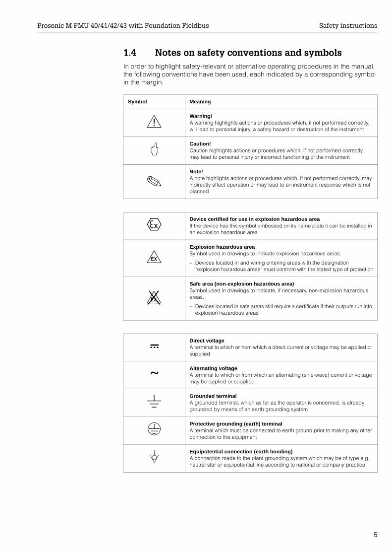
1.4 Notes on safety conventions and symbolsIn order to highlight safety-relevant or alternative operating procedures in the manual, the following conventions have been used, each indicated by a corresponding symbol in the margin.
Symbol Meaning
#Warning!A warning highlights actions or procedures which, if not performed correctly, will lead to personal injury, a safety hazard or destruction of the instrument
"Caution!Caution highlights actions or procedures which, if not performed correctly, may lead to personal injury or incorrect functioning of the instrument
!Note!A note highlights actions or procedures which, if not performed correctly, may indirectly affect operation or may lead to an instrument response which is not planned
0Device certified for use in explosion hazardous areaIf the device has this symbol embossed on its name plate it can be installed in an explosion hazardous area
-Explosion hazardous areaSymbol used in drawings to indicate explosion hazardous areas.
– Devices located in and wiring entering areas with the designation “explosion hazardous areas” must conform with the stated type of protection
.Safe area (non-explosion hazardous area)Symbol used in drawings to indicate, if necessary, non-explosion hazardous areas.
– Devices located in safe areas still require a certificate if their outputs run into explosion hazardous areas
%Direct voltageA terminal to which or from which a direct current or voltage may be applied or supplied
&Alternating voltageA terminal to which or from which an alternating (sine-wave) current or voltage may be applied or supplied
)Grounded terminalA grounded terminal, which as far as the operator is concerned, is already grounded by means of an earth grounding system
*Protective grounding (earth) terminalA terminal which must be connected to earth ground prior to making any other connection to the equipment
+Equipotential connection (earth bonding)A connection made to the plant grounding system which may be of type e.g. neutral star or equipotential line according to national or company practice
Identification Prosonic M FMU 40/41/42/43 with Foundation Fieldbus
6
2 Identification
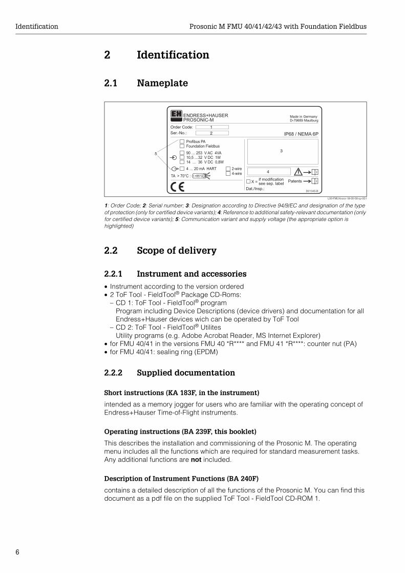
2.1 Nameplate
L00-FMU4xxxx-18-00-00-yy-001
1: Order Code; 2: Serial number; 3: Designation according to Directive 94/9/EC and designation of the type of protection (only for certified device variants); 4: Reference to additional safety-relevant documentation (only for certified device variants); 5: Communication variant and supply voltage (the appropriate option is highlighted)
2.2 Scope of delivery
2.2.1 Instrument and accessories• Instrument according to the version ordered• 2 ToF Tool - FieldTool® Package CD-Roms:
– CD 1: ToF Tool - FieldTool® programProgram including Device Descriptions (device drivers) and documentation for all Endress+Hauser devices wich can be operated by ToF Tool
– CD 2: ToF Tool - FieldTool® UtilitesUtility programs (e.g. Adobe Acrobat Reader, MS Internet Explorer)
• for FMU 40/41 in the versions FMU 40 *R**** and FMU 41 *R****: counter nut (PA)• for FMU 40/41: sealing ring (EPDM)
2.2.2 Supplied documentation
Short instructions (KA 183F, in the instrument)
intended as a memory jogger for users who are familiar with the operating concept of Endress+Hauser Time-of-Flight instruments.
Operating instructions (BA 239F, this booklet)
This describes the installation and commissioning of the Prosonic M. The operating menu includes all the functions which are required for standard measurement tasks. Any additional functions are not included.
Description of Instrument Functions (BA 240F)
contains a detailed description of all the functions of the Prosonic M. You can find this document as a pdf file on the supplied ToF Tool - FieldTool CD-ROM 1.
Made in GermanyD-79689 Maulburg
Dat./Insp.:
Order Code:
IP68 / NEMA 6PSer.-No.:
90 … 253 V AC 4VA10,5 …32 V DC 1W14 … 36 V DC 0,8W
4 … 20 mA HART 2-wire4-wire
Profibus PAFoundation Fieldbus
ENDRESS+HAUSER
t >85°CTA > 70°C :
D01345-B
if modificationsee sep. labelX = Patents
PROSONIC-M
1
2
3
4
5
Prosonic M FMU 40/41/42/43 with Foundation Fieldbus Identification
7
Safety instructions
Additional safety instructions (XA, ZE, ZD) are supplied with certified device versions. Refer to the nameplate for the names of the safety instructions that apply to your device variant.
2.3 Certificates and approvalsCE mark, declaration of conformityThe instrument is designed to meet state-of-the-art safety requirements, has been tested and left the factory in a condition in which it is safe to operate. The instrument complies with the applicable standards and regulations in accordance with EN 61010 "Protection Measures for Electrical Equipment for Measurement, Control, Regulation and Laboratory Procedures". The instrument described in this manual thus complies with the statutory requirements of the EG directives. Endress+Hauser confirms the successful testing of the instrument by affixing to it the CE mark.
2.4 Registered trademarksToF®
Registered trademark of the company Endress+Hauser GmbH+Co. KG, Maulburg, Germany
PulseMaster®
Registered trademark of the company Endress+Hauser GmbH+Co. KG, Maulburg, Germany
Foundation™ FieldbusRegistered trademark of Fieldbus Foundation Austin, Texas, USA
Installation Prosonic M FMU 40/41/42/43 with Foundation Fieldbus
8
3 Installation
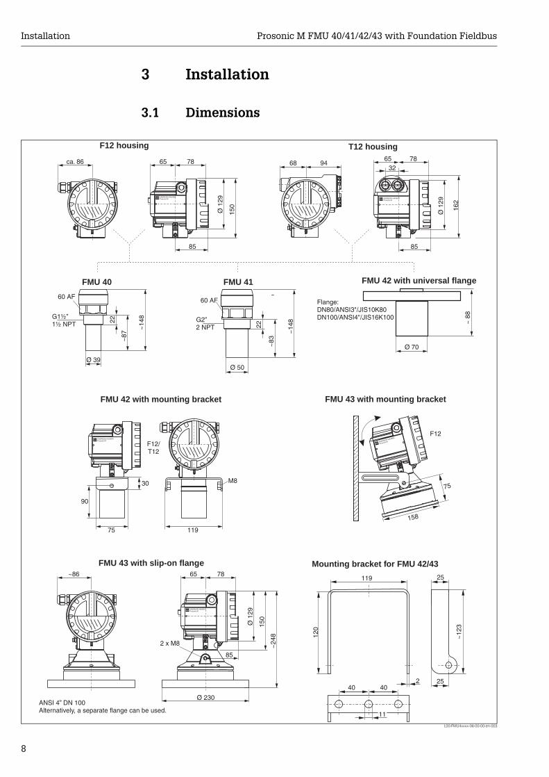
3.1 Dimensions
L00-FMU4xxxx-06-00-00-en-003
65 78
Ø 1
29
ca. 86 78
8585
65
Ø 1
29
162
150
68 94
~14
8
~83
22
FMU 40 FMU 41
Ø 39Ø 50
~14
8
~87
22
85
2 x M8
65 78
Ø 1
29
~86
150
~24
8
11
119
2
25
120
~12
3
25
ENDRESS+HAUSERProsonic M ENDRESS+HAUSER
Prosonic M
ENDRESS+HAUSERProsonic M
ENDRESS+HAUSER
Prosonic M
40 40
32
158
Ø 230
~ 8
8
Ø 70
ENDRESS+HAUSERProsonic M
F12/T12
75
30
119
M8
F12
90
75
F12 housing T12 housing
FMU 43 with slip-on flange
FMU 43 with mounting bracket
60 AF
G2”2 NPT
G1½”1½ NPT
60 AF
ANSI 4” DN 100Alternatively, a separate flange can be used.
Mounting bracket for FMU 42/43
FMU 42 with universal flange
Flange:DN80/ANSI3"/JIS10K80DN100/ANSI4"/JIS16K100
FMU 42 with mounting bracket
Prosonic M FMU 40/41/42/43 with Foundation Fieldbus Installation
9
3.2 Installation variants
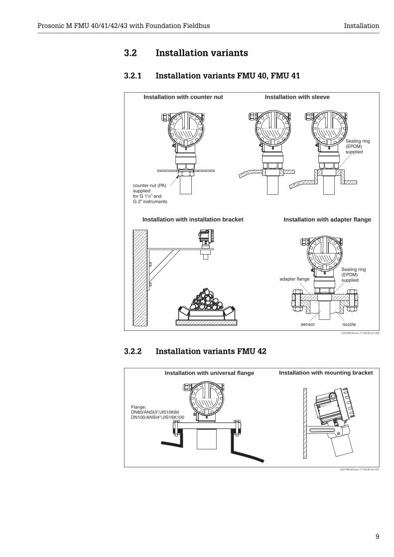
3.2.1 Installation variants FMU 40, FMU 41
L00-FMU4xxxx-17-00-00-en-002
3.2.2 Installation variants FMU 42
L00-FMU42xxxx-17-00-00-en-001
ENDRESS+HAUSERProsonic M
Installation with sleeveInstallation with counter nut
Installation with installation bracket
counter nut (PA)suppliedfor G 1½” andG 2” instruments
adapter flange
sensor nozzle
Sealing ring(EPDM)supplied
Installation with adapter flange
Sealing ring(EPDM)supplied
ENDRESS+HAUSER
Prosonic M
Installation with universal flange
Flange:DN80/ANSI3"/JIS10K80DN100/ANSI4"/JIS16K100
Installation with mounting bracket
Installation Prosonic M FMU 40/41/42/43 with Foundation Fieldbus
10
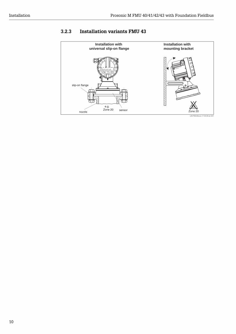
3.2.3 Installation variants FMU 43
L00-FMU43xxxx-17-00-00-en-001
ENDRESS+HAUSER
Prosonic M
Installation withmounting bracket
Installation withuniversal slip-on flange
slip-on flange
sensornozzle
e.g.Zone 20
.Zone 20
Prosonic M FMU 40/41/42/43 with Foundation Fieldbus Installation
11
3.3 Installation conditions
3.3.1 Installation conditions for level measurements
L00-FMU4xxxx-17-00-00-de-005
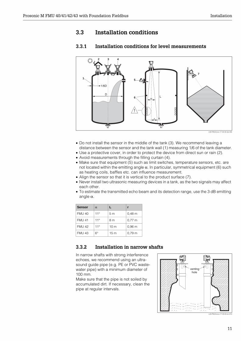
• Do not install the sensor in the middle of the tank (3). We recommend leaving a distance between the sensor and the tank wall (1) measuring 1/6 of the tank diameter.
• Use a protective cover, in order to protect the device from direct sun or rain (2).• Avoid measurements through the filling curtain (4).• Make sure that equipment (5) such as limit switches, temperature sensors, etc. are
not located within the emitting angle α. In particular, symmetrical equipment (6) such as heating coils, baffles etc. can influence measurement.
• Align the sensor so that it is vertical to the product surface (7).• Never install two ultrasonic measuring devices in a tank, as the two signals may affect
each other.• To estimate the transmitted echo beam and its detection range, use the 3 dB emitting
angle α.
3.3.2 Installation in narrow shafts
1
2 3 4
5
6
1/6D
7
D
r
α L
Sensor α L r
FMU 40 11° 5 m 0,48 m
FMU 41 11° 8 m 0,77 m
FMU 42 11° 10 m 0,96 m
FMU 43 6° 15 m 0,79 m
In narrow shafts with strong interference echoes, we recommend using an ultra-sound guide pipe (e.g. PE or PVC waste-water pipe) with a minimum diameter of 100 mm.Make sure that the pipe is not soiled by accumulated dirt. If necessary, clean the pipe at regular intervals.
L00-FMU4xxxx-17-00-00-en-010
ENDRESS+HAUSERProsonic MENDRESS+HAUSERProsonic M
ENDRESS+HAUSERProsonic MENDRESS+HAUSERProsonic M
ventinghole
Installation Prosonic M FMU 40/41/42/43 with Foundation Fieldbus
12
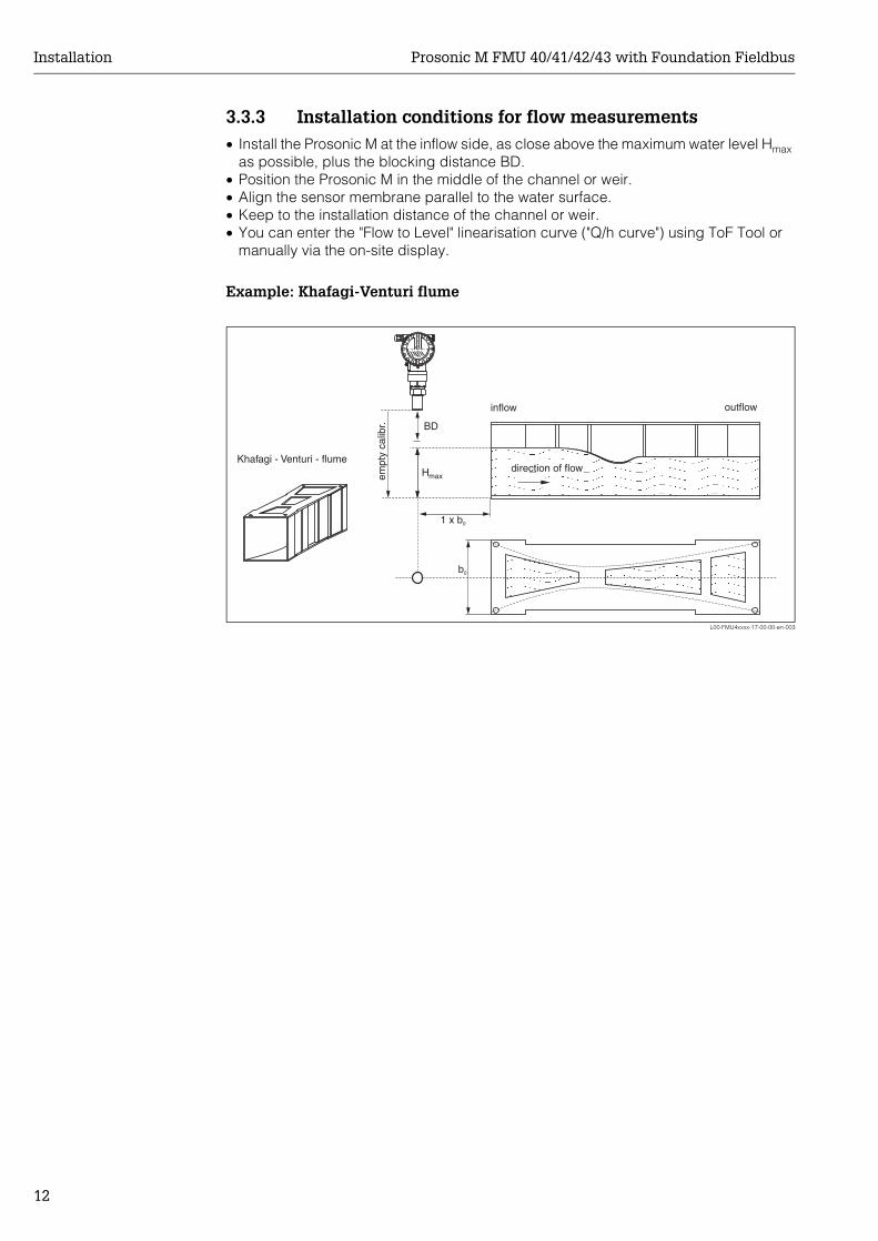
3.3.3 Installation conditions for flow measurements• Install the Prosonic M at the inflow side, as close above the maximum water level Hmax
as possible, plus the blocking distance BD.• Position the Prosonic M in the middle of the channel or weir.• Align the sensor membrane parallel to the water surface.• Keep to the installation distance of the channel or weir.• You can enter the "Flow to Level" linearisation curve ("Q/h curve") using ToF Tool or
manually via the on-site display.
Example: Khafagi-Venturi flume
L00-FMU4xxxx-17-00-00-en-003
1 x b0
b0
BD
Hmax
Khafagi - Venturi - flumedirection of flow
inflow outflow
empt
y ca
libr.

Prosonic M FMU 40/41/42/43 with Foundation Fieldbus Installation
13
Example: Triangular weir
L00-FMU4xxxx-17-00-00-en-012
max
max
max
max
empt
y ca
libr.
(= full calibr.)
min. 3 H
H
min. 2 H
α
min. 2 H
BD
Installation Prosonic M FMU 40/41/42/43 with Foundation Fieldbus
14
3.4 Measuring range
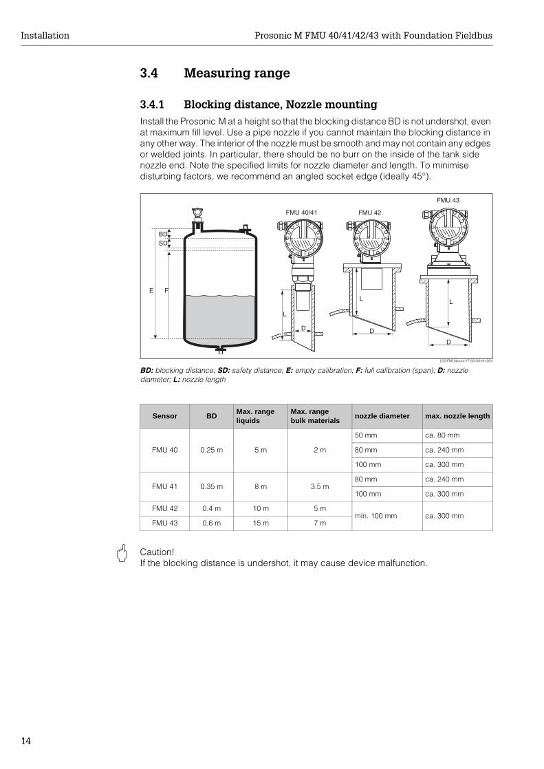
3.4.1 Blocking distance, Nozzle mountingInstall the Prosonic M at a height so that the blocking distance BD is not undershot, even at maximum fill level. Use a pipe nozzle if you cannot maintain the blocking distance in any other way. The interior of the nozzle must be smooth and may not contain any edges or welded joints. In particular, there should be no burr on the inside of the tank side nozzle end. Note the specified limits for nozzle diameter and length. To minimise disturbing factors, we recommend an angled socket edge (ideally 45°).
L00-FMU4xxxx-17-00-00-en-004
BD: blocking distance; SD: safety distance; E: empty calibration; F: full calibration (span); D: nozzle diameter; L: nozzle length
" Caution! If the blocking distance is undershot, it may cause device malfunction.
FE
BDSD
L
D
FMU 40/41
L
D
FMU 43
L
D
FMU 42
Sensor BDMax. rangeliquids
Max. rangebulk materials
nozzle diameter max. nozzle length
FMU 40 0.25 m 5 m 2 m
50 mm ca. 80 mm
80 mm ca. 240 mm
100 mm ca. 300 mm
FMU 41 0.35 m 8 m 3.5 m80 mm ca. 240 mm
100 mm ca. 300 mm
FMU 42 0.4 m 10 m 5 mmin. 100 mm ca. 300 mm
FMU 43 0.6 m 15 m 7 m
Prosonic M FMU 40/41/42/43 with Foundation Fieldbus Installation
15
3.4.2 Safety distanceIf the level rises to the safety distance SD, the device switches to warning or alarm status.The size of SD can be set freely in the "Safety distance" (015) function.The "in safety distance" (016) function defines how the device reacts if the level enters the safety distance.
There are three options:• Warning: The device outputs an error message but continues measurement.• Alarm: The device outputs an error message. The output signal assumes the value
defined in the "Output on alarm" (011) function (MAX, MIN, user-specific value or holds the last value). As soon as the level drops below the safety distance, the device recommences measurement.
• Self holding: The device reacts in the same way as for an alarm. However, the alarm condition continues after the level drops below the safety distance. The device only recommences measurement when you cancel the alarm using the "Ackn. alarm" (017) function.
3.4.3 RangeThe sensor range is dependent on the measuring conditions. Refer to Technical Information TI 365F/00/en for an estimation. The maximum range is shown in the above diagram (valid for good conditions).
3.5 Installation hint for FMU 40/41
Sensor maximum range
FMU 40 5 m
FMU 41 8 m
FMU 42 10 m
FMU 43 15 m
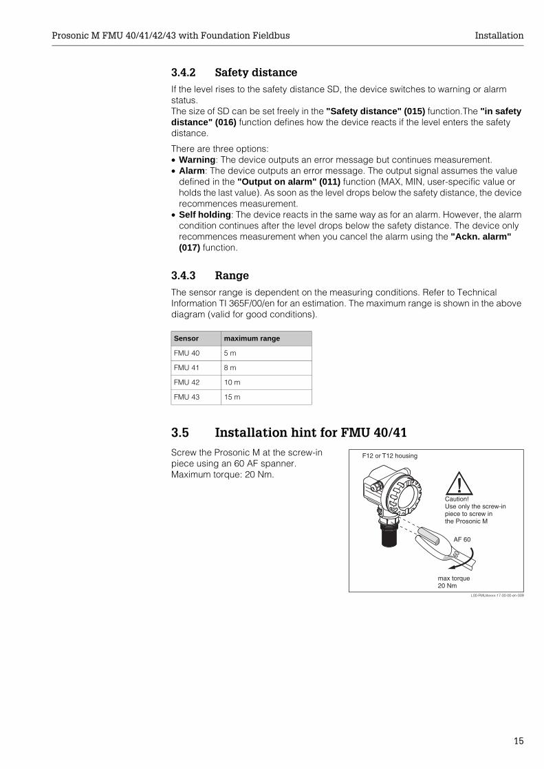
Screw the Prosonic M at the screw-in piece using an 60 AF spanner.Maximum torque: 20 Nm.
L00-FMU4xxxx-17-00-00-en-009
60
AF 60
max torque20 Nm
Caution!Use only the screw-inpiece to screw inthe Prosonic M
F12 or T12 housing
Installation Prosonic M FMU 40/41/42/43 with Foundation Fieldbus
16
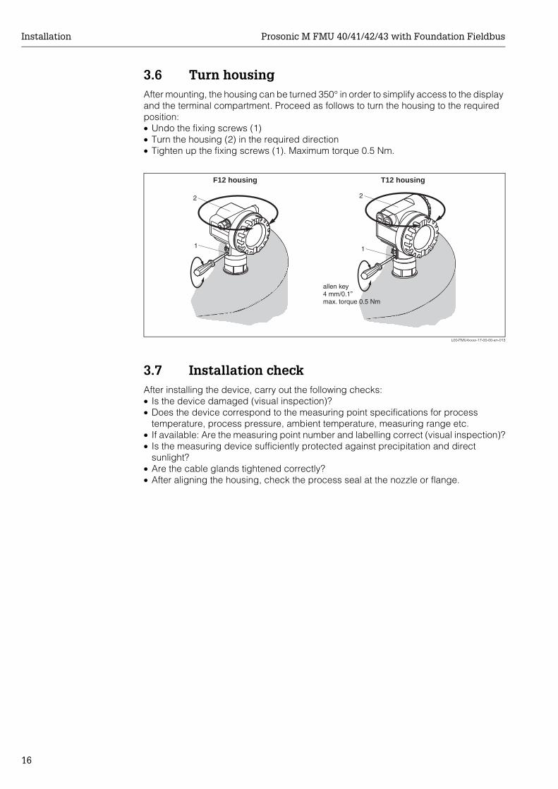
3.6 Turn housingAfter mounting, the housing can be turned 350° in order to simplify access to the display and the terminal compartment. Proceed as follows to turn the housing to the required position:• Undo the fixing screws (1)• Turn the housing (2) in the required direction• Tighten up the fixing screws (1). Maximum torque 0.5 Nm.
L00-FMU4xxxx-17-00-00-en-013
3.7 Installation checkAfter installing the device, carry out the following checks:• Is the device damaged (visual inspection)?• Does the device correspond to the measuring point specifications for process
temperature, process pressure, ambient temperature, measuring range etc.• If available: Are the measuring point number and labelling correct (visual inspection)?• Is the measuring device sufficiently protected against precipitation and direct
sunlight?• Are the cable glands tightened correctly?• After aligning the housing, check the process seal at the nozzle or flange.
11
2 2
F12 housing T12 housing
allen key4 mm/0.1”max. torque 0.5 Nm
Prosonic M FMU 40/41/42/43 with Foundation Fieldbus Wiring
17
4 Wiring
4.1 Electrical connection
" Caution! Before connection please note the following:• The power supply must be identical to the data on the nameplate.• Switch off power supply before connecting up the instrument.• Connect equipotential bonding to transmitter ground terminal before connecting up
the instrument (s. section "Potential matching")
# Warning! When you use the measuring system in hazardous areas, make sure to comply with national standards and the specifications in the safety instructions (XA’s). Make sure you use the specified cable gland.
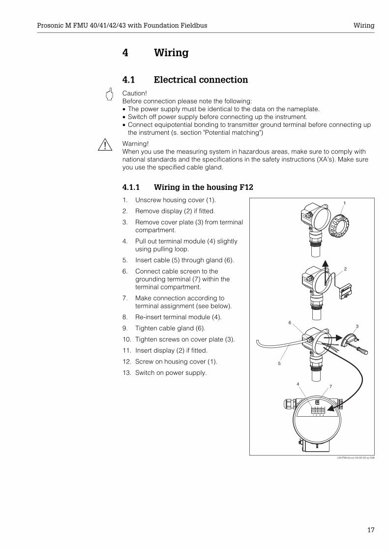
4.1.1 Wiring in the housing F12
1. Unscrew housing cover (1).
2. Remove display (2) if fitted.
3. Remove cover plate (3) from terminal compartment.
4. Pull out terminal module (4) slightly using pulling loop.
5. Insert cable (5) through gland (6).
6. Connect cable screen to the grounding terminal (7) within the terminal compartment.
7. Make connection according to terminal assignment (see below).
8. Re-insert terminal module (4).
9. Tighten cable gland (6).
10. Tighten screws on cover plate (3).
11. Insert display (2) if fitted.
12. Screw on housing cover (1).
13. Switch on power supply.
L00-FMU4xxxx-04-00-00-yy-008
1 2 3 4
ENDRESS+HAUSER
ENDRESS+HAUSER
3
5
4
1
2
6
7
Wiring Prosonic M FMU 40/41/42/43 with Foundation Fieldbus
18
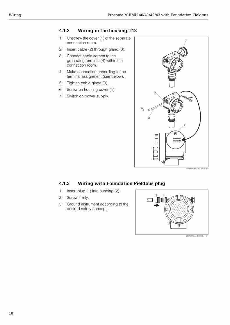
4.1.2 Wiring in the housing T12
4.1.3 Wiring with Foundation Fieldbus plug
1. Unscrew the cover (1) of the separate connection room.
2. Insert cable (2) through gland (3).
3. Connect cable screen to the grounding terminal (4) within the connection room.
4. Make connection according to the terminal assignment (see below).
5. Tighten cable gland (3).
6. Screw on housing cover (1).
7. Switch on power supply.
L00-FMU4xxxx-04-00-00-yy-009
3
2
1 2 3 4
4
1
1. Insert plug (1) into bushing (2).
2. Screw firmly.
3. Ground instrument according to the desired safety concept.
L00-FMU4xxxx-04-00-00-yy-011
12
Prosonic M FMU 40/41/42/43 with Foundation Fieldbus Wiring
19
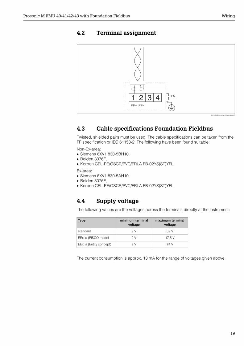
4.2 Terminal assignment
L00-FMR2xxxx-04-00-00-de-007
4.3 Cable specifications Foundation FieldbusTwisted, shielded pairs must be used. The cable specifications can be taken from the FF specification or IEC 61158-2. The following have been found suitable:
Non-Ex-area:• Siemens 6XV1 830-5BH10,• Belden 3076F,• Kerpen CEL-PE/OSCR/PVC/FRLA FB-02YS(ST)YFL.
Ex-area:• Siemens 6XV1 830-5AH10,• Belden 3076F,• Kerpen CEL-PE/OSCR/PVC/FRLA FB-02YS(ST)YFL.
4.4 Supply voltageThe following values are the voltages across the terminals directly at the instrument:
The current consumption is approx. 13 mA for the range of voltages given above.
Type minimum terminal voltage
maximum terminal voltage
standard 9 V 32 V
EEx ia (FISCO model 9 V 17,5 V
EEx ia (Entity concept) 9 V 24 V
Wiring Prosonic M FMU 40/41/42/43 with Foundation Fieldbus
20
4.5 Recommended connection
L00-FMP4xxxx-17-00-00-yy-043
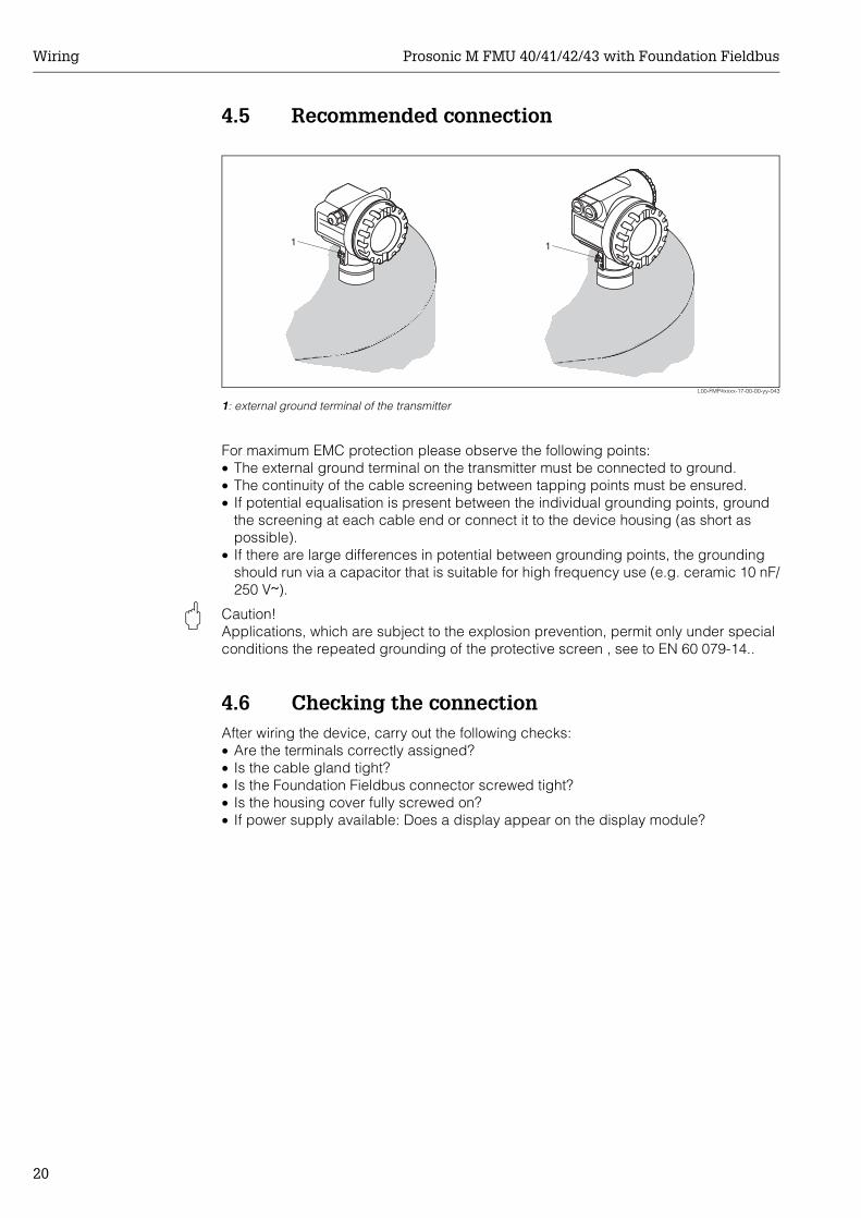
1: external ground terminal of the transmitter
For maximum EMC protection please observe the following points:• The external ground terminal on the transmitter must be connected to ground.• The continuity of the cable screening between tapping points must be ensured.• If potential equalisation is present between the individual grounding points, ground
the screening at each cable end or connect it to the device housing (as short as possible).
• If there are large differences in potential between grounding points, the grounding should run via a capacitor that is suitable for high frequency use (e.g. ceramic 10 nF/250 V&).
" Caution! Applications, which are subject to the explosion prevention, permit only under special conditions the repeated grounding of the protective screen , see to EN 60 079-14..
4.6 Checking the connectionAfter wiring the device, carry out the following checks:• Are the terminals correctly assigned?• Is the cable gland tight?• Is the Foundation Fieldbus connector screwed tight?• Is the housing cover fully screwed on?• If power supply available: Does a display appear on the display module?
11

Prosonic M FMU 40/41/42/43 with Foundation Fieldbus Operation
21
5 Operation
5.1 Display and operating elements
5.1.1 On-site display VU 331The LCD module VU 331 for display and operation is located beneath the housing cover. The measured value is legible through the glass in the cover. Open the cover to operate the device.
L00-FMxxxxxx-07-00-00-en-001
ENDRESS + HAUSER
E+–
ENDRESS+HAUSER
MICROPILOT II
ENDRESS+HAUSER
MICROPILOT II
IP 65IP 65
Order Code:Ser.-No.:
Order Code:Ser.-No.:
MessbereichMeasuring range
MessbereichMeasuring rangeU 16...36 V DC
4...20 mA
U 16...36 V DC4...20 mA
max. 20 m
max. 20 m
Made in
Germ
any
M
aulb
urg
Made in
Germ
any
M
aulb
urg
T>70°C :
A
t >85°C
T>70°C :
A
t >85°C
LCD(liquid crystal display)
Symbols 3 keys
Operation Prosonic M FMU 40/41/42/43 with Foundation Fieldbus
22
5.1.2 Display appearance
L00-FMxxxxxx-07-00-00-en-002
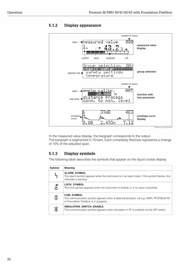
In the measured value display, the bargraph corresponds to the output.The bargraph is segmented in 10 bars. Each completely filled bar represents a change of 10% of the adjusted span.
5.1.3 Display symbolsThe following table describes the symbols that appear on the liquid crystal display:
�
bargraph
help texts
envelopecurve
label
position in menu
value unitsymbol
measured valuedisplay
group selection
function withfree parameter
envelope curvedisplay
label
position in menu
selection list
Sybmol Meaning
ALARM_SYMBOLThis alarm symbol appears when the instrument is in an alarm state. If the symbol flashes, this indicates a warning.
LOCK_SYMBOLThis lock symbol appears when the instrument is locked,i.e. if no input is possible.
COM_SYMBOLThis communication symbol appears when a data transmission via e.g. HART, PFOFIBUS-PA or Foundation Fieldbus is in progress.
SIMULATION_SWITCH_ENABLEThis communication symbol appears when simulation in FF is enabled via the DIP switch.
Prosonic M FMU 40/41/42/43 with Foundation Fieldbus Operation
23
5.1.4 Function of the keys
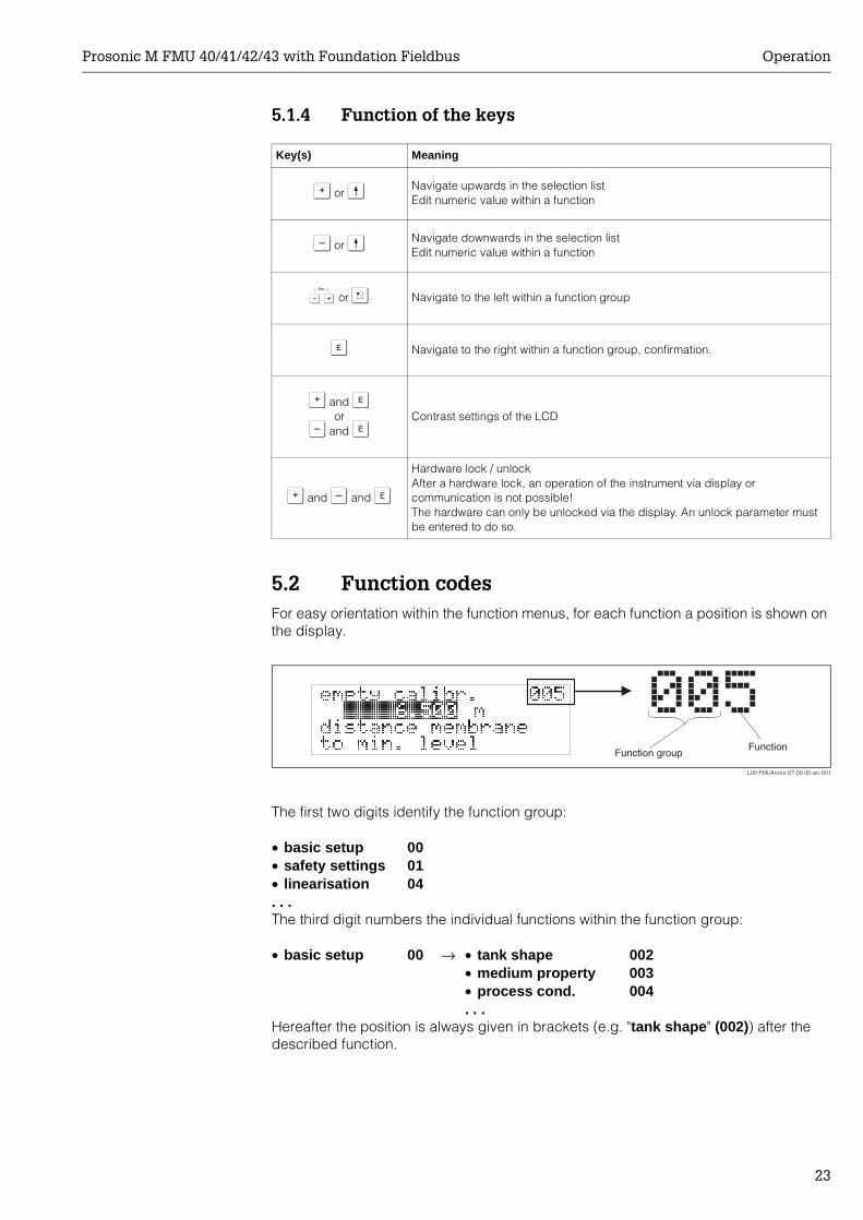
5.2 Function codesFor easy orientation within the function menus, for each function a position is shown on the display.
L00-FMU4xxxx-07-00-00-en-001
The first two digits identify the function group:
The third digit numbers the individual functions within the function group:
Hereafter the position is always given in brackets (e.g. "tank shape" (002)) after the described function.
Key(s) Meaning
O or VNavigate upwards in the selection listEdit numeric value within a function
S or VNavigate downwards in the selection listEdit numeric value within a function
X or Z Navigate to the left within a function group
F Navigate to the right within a function group, confirmation.
O and For
S and FContrast settings of the LCD
O and S and F
Hardware lock / unlockAfter a hardware lock, an operation of the instrument via display orcommunication is not possible!The hardware can only be unlocked via the display. An unlock parameter must be entered to do so.
• basic setup 00• safety settings 01• linearisation 04. . .
• basic setup 00 → • tank shape 002• medium property 003• process cond. 004. . .
FunctionFunction group
���
Operation Prosonic M FMU 40/41/42/43 with Foundation Fieldbus
24
5.3 Foundation Fieldbus interface
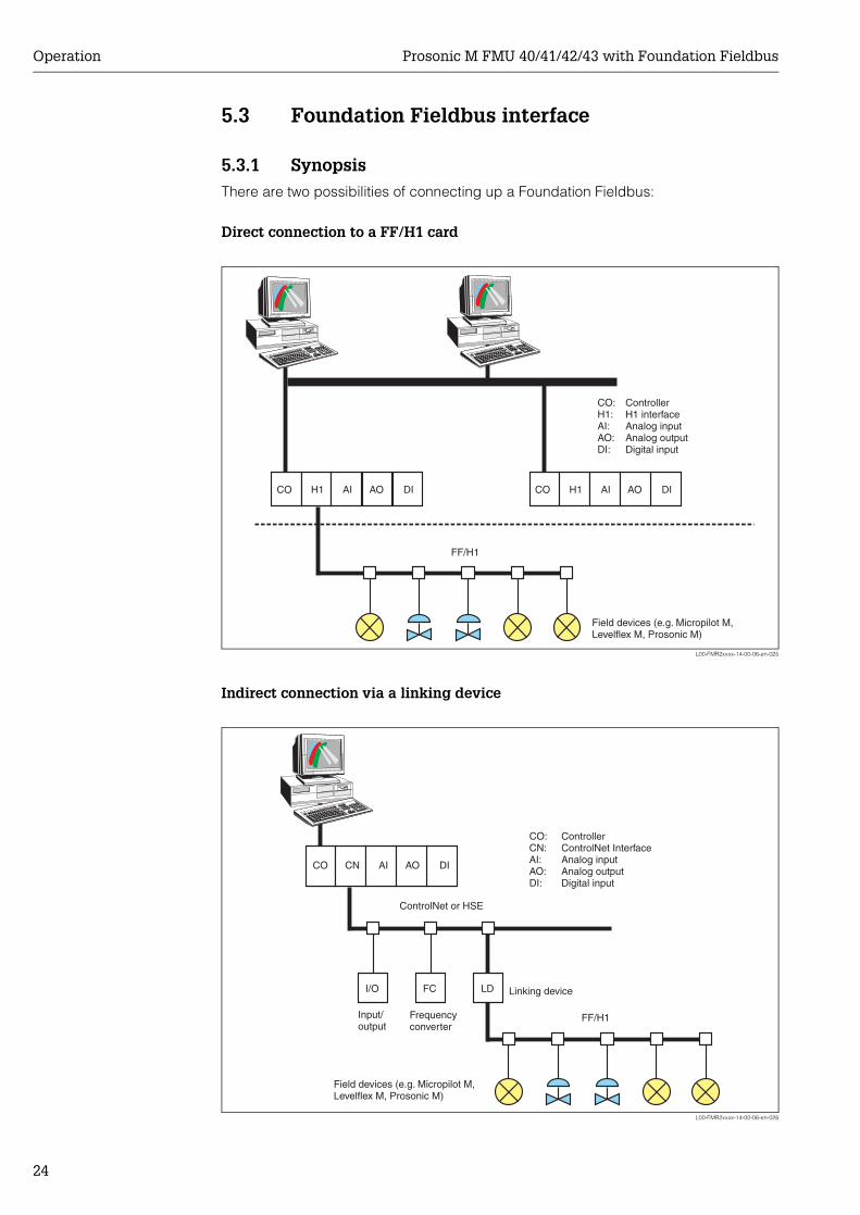
5.3.1 SynopsisThere are two possibilities of connecting up a Foundation Fieldbus:
Direct connection to a FF/H1 card
L00-FMR2xxxx-14-00-06-en-025
Indirect connection via a linking device
L00-FMR2xxxx-14-00-06-en-026
CO H1 AI AO DI
FF/H1
CO H1 AI AO DI
CO:H1:AI:AO:DI:
ControllerH1 interfaceAnalog inputAnalog outputDigital input
Field devices (e.g. Micropilot M,Levelflex M, Prosonic M)
CO
I/O FC LD
CN AI AO DI
FF/H1
CO:CN:AI:AO:DI:
ControllerControlNet InterfaceAnalog inputAnalog outputDigital input
Field devices (e.g. Micropilot M,Levelflex M, Prosonic M)
Linking device
Frequencyconverter
Input/output
ControlNet or HSE
Prosonic M FMU 40/41/42/43 with Foundation Fieldbus Operation
25
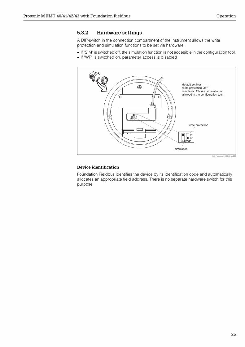
5.3.2 Hardware settingsA DIP-switch in the connection compartment of the instrument allows the write protection and simulation functions to be set via hardware.
• If "SIM" is switched off, the simulation function is not accesible in the configuration tool.• If "WP" is switched on, parameter access is disabled
L00-FMxxxxxx-19-00-00-en-002
Device identification
Foundation Fieldbus identifies the device by its identification code and automatically allocates an appropriate field address. There is no separate hardware switch for this purpose.
ENDRESS+HAUSER
MICROPILOT II
ENDRESS+HAUSER
MICROPILOT II
IP 65IP 65
Order Code:Ser.-No.:
Order Code:Ser.-No.:
MessbereichMeasuring range
MessbereichMeasuring rangeU 16...36 V DC
4...20 mA
U 16...36 V DC4...20 mA
max. 20 m
max. 20 m
Made in
Germ
any
M
aulb
urg
Made in
Germ
any
M
aulb
urg
T>70°C :
A
t >85°C
T>70°C :
A
t >85°C
onoff
SIM WP
SIM WPoffon
simulation
write protection
default settings:write protection OFFsimulation ON (i.e. simulation isallowed in the configuration tool)
Operation Prosonic M FMU 40/41/42/43 with Foundation Fieldbus
26
5.3.3 Network configurationDuring the configuration of the FF network the device description (DD) of the Prosonic M must be downloaded into the directory foreseen for it.
• Start the interface configuration tool.• Configure the interface.• Call the DD download routine• Download the device descriptions (.ffo and .sym files) to the directory offered.• When the configuration is complete, close the tool and the FF stack (if open).
The Prosonic M device descriptions can be ordered direct from Endress+Hauser or downloaded from our website www.endress.com. They contain all data necessary to operate Endress+Hauser Foundation Fieldbus devices.
Example: Start-up using the NI-Fieldbus configurator
Start the bus configuration tool. After start-up, the tool shows the network configuration in the form of an expandable tree. If the Prosonic M has been connected correctly, it can now be identified:
A double click on the name reveals the device data.
The device ID is made up of the following components:
whereby:
A right-hand mouse click on the name opens up a menu from which the PD_TAG and NODE_ADDRESS can be changed.
A click on the name expands the device tree to show the function blocks available for it:
E+H_PROSONIC_M_XXXXXXXX
PD_TAG the physical name of the device
DEVICE_ID the unique device identifier
NODE_ADDRESS the fieldbus node to which the device is connected (is automatically allocated by the Configurator)
Device_ID = 452B48100F-XXXXXXXX
452B48 ID code for Endress+Hauser
1011 ID code for Prosonic M
XXXXXXXX Device serial number, as printed on the nameplate
E+H_PROSONIC_M_XXXXXXXXRESOURCE_XXXXXX (RB2)TRANSDUCER_XXXXXX (TBRL)ANALOG_INPUT_1_XXXXXX (AI)ANALOG_INPUT_2_XXXXXX (AI)PID_XXXXXX(PID)AR_XXXXXX (AR)IS_XXXXXX (IS)SC_XXXXXX (SC)IT_XXXXXX (IT)
Prosonic M FMU 40/41/42/43 with Foundation Fieldbus Operation
27
5.3.4 Block model of the Prosonic MThe Prosonic M contains the follwoing blocks:• Resource Block (RB2)
s. Operating Instructions BA 013S: "Foundation Fieldbus - Overview"• Transducer Block (TB)
contains the parameters relevant to the measurement• Analog-Input-Block 1 bzw. 2 (AI)
scale the signal of the Transducer Block and transmit them to the PLCS• PID Block (PID)
s. Operating Instructions BA 013S: "Foundation Fieldbus - Overview"• Arithmetic Block (AR)
s. Operating Instructions BA 013S: "Foundation Fieldbus - Overview"• Input Selector Block (IS)
s. Operating Instructions BA 013S: "Foundation Fieldbus - Overview"• Signal Characterizer Block (SC)
s. Operating Instructions BA 013S: "Foundation Fieldbus - Overview"• Integrator Block (IT)
s. Operating Instructions BA 013S: "Foundation Fieldbus - Overview"
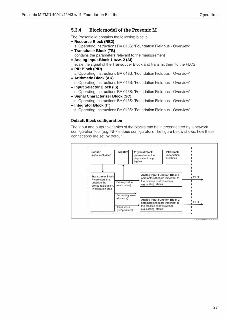
Default Block configuration
The input and output variables of the blocks can be interconnected by a network configuration tool (e.g. NI-Fieldbus configurator). The figure below shows, how these connections are set by default.
L00-FMU4XXXX-02-00-00-en-003
OUT
OUT
Physical Blockparameters of thephysical unit, e.g.tag No.
DisplaySensorsignal evaluation
Transducer BlockParameters thatdescribe thedevice (calibration,linearisation etc.)
Analog Input Function Block 1parameters that are important tothe process control system,e.g. scaling, status
Analog Input Function Block 2parameters that are important tothe process control system,e.g. scaling, status
PID BlockAutomationfunctions
Primary value(main value)
Secondary value(distance)
Third value(temperature)
Operation Prosonic M FMU 40/41/42/43 with Foundation Fieldbus
28
5.3.5 Resource Block
Operation
The resource block contains the parameters used to describe physical resources of the device. It has no linkable inputs or outputs.The resource block is opened by a click on the resource line.If the NI-FBUS Configurator is being used, a series of file tabs appears on the screen. The files can be opened to view and/or edit the parameters in the following table. A short description of the parameter function appears on the side of the screen. A change in the parameter is stored by pressing the WRITE CHANGES button when the block is out of service. Press the READ ALL button to check the values stored in the device.
Parameters
The function of the resource block parameters not described here can can be taken from the Foundation Fieldbus specification, see www.fieldbus.org.
E+H_PROSONIC_M_XXXXXXXXRESOURCE_XXXXXX (RB2)TRANSDUCER_XXXXXX (TBUL)ANALOG_INPUT_1_XXXXXX (AI)
Parameter Description
TAG_DESC User description of the intended application of the block.
MODE_BLK Lists the actual, target, permitted and normal operating modes of the block.– Target: changes the operating mode of the block– Actual: indicates the current operating mode of the block– Permitted: states which operating modes are allowed– Normal: indicates the normal operating mode of the block
The possible operating modes of the resources block are:– AUTO: the block is operating as normal– OOS: the block is out of service.
If the resource block is out of service, then all blocks within the device (resource) are forced into the same status.
RS_STATE Indicates the state of the resource block application state machine– On-line: block in AUTO mode– Standby: block in OOS mode
WRITE_LOCK Indicates the status of DIP-switch WP– LOCKED: device data can be modified– NOT LOCKED: device data can be modified
RESTART Allows a manual restart:– UNINITIALISED: no status– RUN: normal operational status– RESOURCE: resets the resource block parameters– DEFAULTS: Resets all Foundation Fieldbus parameters within the
device, but not the manufacturer specific parameters.– PROCESSOR: make a warm start of the processor
BLOCK_ERROR Shows error status of software and hardware components– Out-of-Service: the block is in OOS mode– Simulation active: shows the setting of DIP-switch SIM
BLOCK_ALM Shows any configuration, hardware, connection and system problems in the block. The cause of the alert is to be seen in the subcode field.
Prosonic M FMU 40/41/42/43 with Foundation Fieldbus Operation
29
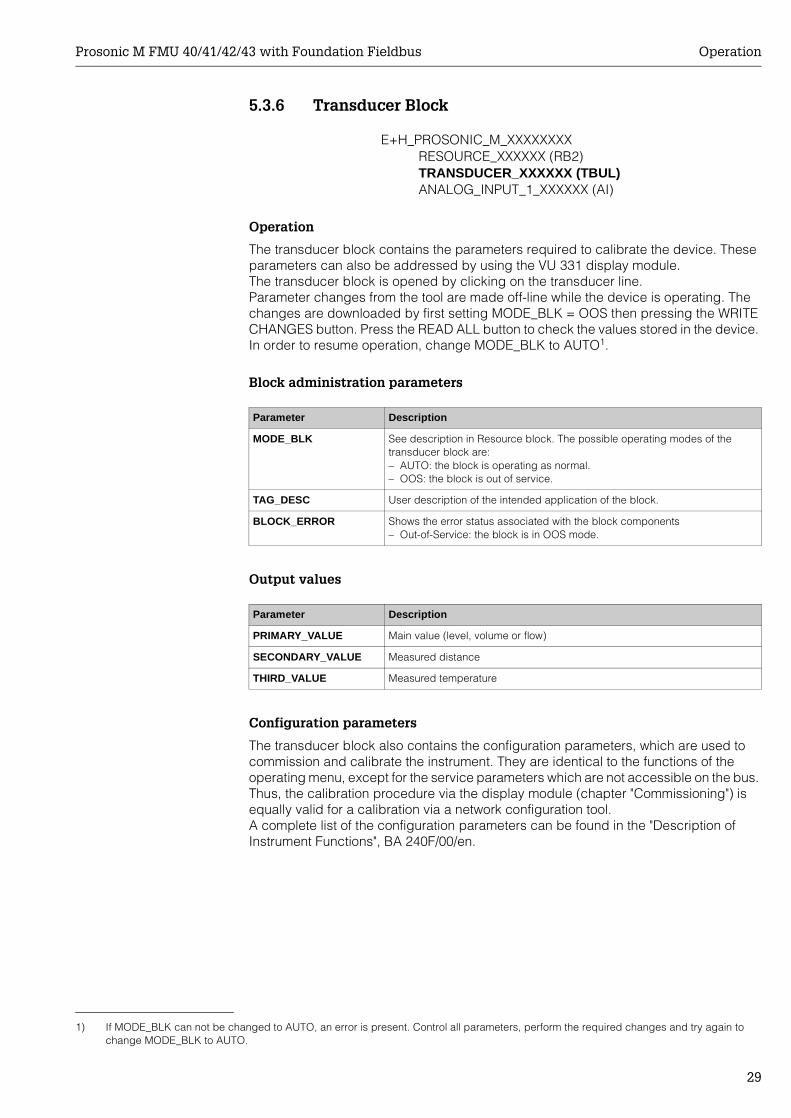
5.3.6 Transducer Block
Operation
The transducer block contains the parameters required to calibrate the device. These parameters can also be addressed by using the VU 331 display module. The transducer block is opened by clicking on the transducer line.Parameter changes from the tool are made off-line while the device is operating. The changes are downloaded by first setting MODE_BLK = OOS then pressing the WRITE CHANGES button. Press the READ ALL button to check the values stored in the device. In order to resume operation, change MODE_BLK to AUTO1.
Block administration parameters
Output values
Configuration parameters
The transducer block also contains the configuration parameters, which are used to commission and calibrate the instrument. They are identical to the functions of the operating menu, except for the service parameters which are not accessible on the bus. Thus, the calibration procedure via the display module (chapter "Commissioning") is equally valid for a calibration via a network configuration tool. A complete list of the configuration parameters can be found in the "Description of Instrument Functions", BA 240F/00/en.
E+H_PROSONIC_M_XXXXXXXXRESOURCE_XXXXXX (RB2)TRANSDUCER_XXXXXX (TBUL)ANALOG_INPUT_1_XXXXXX (AI)
1) If MODE_BLK can not be changed to AUTO, an error is present. Control all parameters, perform the required changes and try again to change MODE_BLK to AUTO.
Parameter Description
MODE_BLK See description in Resource block. The possible operating modes of the transducer block are:– AUTO: the block is operating as normal.– OOS: the block is out of service.
TAG_DESC User description of the intended application of the block.
BLOCK_ERROR Shows the error status associated with the block components– Out-of-Service: the block is in OOS mode.
Parameter Description
PRIMARY_VALUE Main value (level, volume or flow)
SECONDARY_VALUE Measured distance
THIRD_VALUE Measured temperature
Operation Prosonic M FMU 40/41/42/43 with Foundation Fieldbus
30
Methods
The Foundation Fieldbus specification provides for the use of so-called methods to simplify the operation of the device. A method is an interactive sequence of steps that must be followed in order to obtain a particular function from the device.
The Prosonic M has got the following methods:• Set to customer default• Basic setup• Safety settings• Acknowledge alarm• temperature• Linearisation• Extended calibration• Output• Display• Diagnostics• System parameters• Lock TB Manufacturer parameters
Most of these methods are identical to the respective function group in the operating menu. A detailed description of them can be found in the "Description of Instrument functions", BA 240F.
Prosonic M FMU 40/41/42/43 with Foundation Fieldbus Operation
31
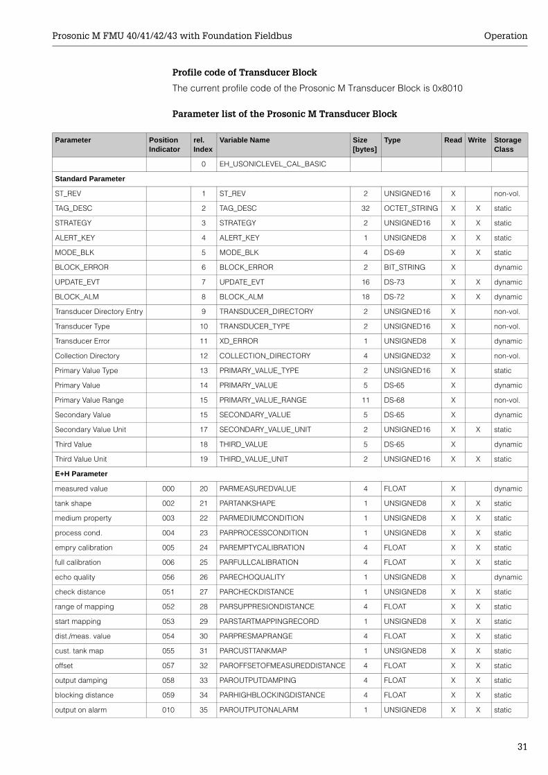
Profile code of Transducer Block
The current profile code of the Prosonic M Transducer Block is 0x8010
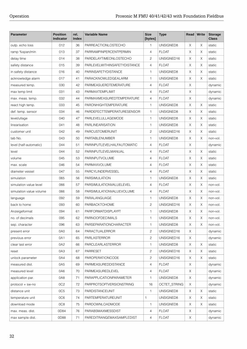
Parameter list of the Prosonic M Transducer Block
Parameter Position Indicator
rel.Index
Variable Name Size[bytes]
Type Read Write Storage Class
0 EH_USONICLEVEL_CAL_BASIC
Standard Parameter
ST_REV 1 ST_REV 2 UNSIGNED16 X non-vol.
TAG_DESC 2 TAG_DESC 32 OCTET_STRING X X static
STRATEGY 3 STRATEGY 2 UNSIGNED16 X X static
ALERT_KEY 4 ALERT_KEY 1 UNSIGNED8 X X static
MODE_BLK 5 MODE_BLK 4 DS-69 X X static
BLOCK_ERROR 6 BLOCK_ERROR 2 BIT_STRING X dynamic
UPDATE_EVT 7 UPDATE_EVT 16 DS-73 X X dynamic
BLOCK_ALM 8 BLOCK_ALM 18 DS-72 X X dynamic
Transducer Directory Entry 9 TRANSDUCER_DIRECTORY 2 UNSIGNED16 X non-vol.
Transducer Type 10 TRANSDUCER_TYPE 2 UNSIGNED16 X non-vol.
Transducer Error 11 XD_ERROR 1 UNSIGNED8 X dynamic
Collection Directory 12 COLLECTION_DIRECTORY 4 UNSIGNED32 X non-vol.
Primary Value Type 13 PRIMARY_VALUE_TYPE 2 UNSIGNED16 X static
Primary Value 14 PRIMARY_VALUE 5 DS-65 X dynamic
Primary Value Range 15 PRIMARY_VALUE_RANGE 11 DS-68 X non-vol.
Secondary Value 15 SECONDARY_VALUE 5 DS-65 X dynamic
Secondary Value Unit 17 SECONDARY_VALUE_UNIT 2 UNSIGNED16 X X static
Third Value 18 THIRD_VALUE 5 DS-65 X dynamic
Third Value Unit 19 THIRD_VALUE_UNIT 2 UNSIGNED16 X X static
E+H Parameter
measured value 000 20 PARMEASUREDVALUE 4 FLOAT X dynamic
tank shape 002 21 PARTANKSHAPE 1 UNSIGNED8 X X static
medium property 003 22 PARMEDIUMCONDITION 1 UNSIGNED8 X X static
process cond. 004 23 PARPROCESSCONDITION 1 UNSIGNED8 X X static
empry calibration 005 24 PAREMPTYCALIBRATION 4 FLOAT X X static
full calibration 006 25 PARFULLCALIBRATION 4 FLOAT X X static
echo quality 056 26 PARECHOQUALITY 1 UNSIGNED8 X dynamic
check distance 051 27 PARCHECKDISTANCE 1 UNSIGNED8 X X static
range of mapping 052 28 PARSUPPRESIONDISTANCE 4 FLOAT X X static
start mapping 053 29 PARSTARTMAPPINGRECORD 1 UNSIGNED8 X X static
dist./meas. value 054 30 PARPRESMAPRANGE 4 FLOAT X X static
cust. tank map 055 31 PARCUSTTANKMAP 1 UNSIGNED8 X X static
offset 057 32 PAROFFSETOFMEASUREDDISTANCE 4 FLOAT X X static
output damping 058 33 PAROUTPUTDAMPING 4 FLOAT X X static
blocking distance 059 34 PARHIGHBLOCKINGDISTANCE 4 FLOAT X X static
output on alarm 010 35 PAROUTPUTONALARM 1 UNSIGNED8 X X static
Operation Prosonic M FMU 40/41/42/43 with Foundation Fieldbus
32
outp. echo loss 012 36 PARREACTIONLOSTECHO 1 UNSIGNED8 X X static
ramp %span/min 013 37 PARRAMPINPERCENTPERMIN 4 FLOAT X X static
delay time 014 38 PARDELAYTIMEONLOSTECHO 2 UNSIGNED16 X X static
safety distance 015 39 PARLEVELWITHINSAFETYDISTANCE 4 FLOAT X X static
in safety distance 016 40 PARINSAFETYDISTANCE 1 UNSIGNED8 X X static
acknowledge alarm 017 41 PARACKNOWLEDGEALARM 1 UNSIGNED8 X X static
measured temp. 030 42 PARMEASUERDTEMERATURE 4 FLOAT X dynamic
max temp limit 031 43 PARMAXTEMPLIMIT 4 FLOAT X dynamic
max. meas. temp. 032 44 PARMAXMEASUREDTEMPERATURE 4 FLOAT X dynamic
react high temp. 033 45 PARONHIGHTEMPERATURE 1 UNSIGNED8 X X static
def. temp. sensor 034 46 PARDEFECTTEMPERATURESENSOR 1 UNSIGNED8 X X static
level/ullage 040 47 PARLEVELULLAGEMODE 1 UNSIGNED8 X X static
linearisation 041 48 PARLINEARISATION 1 UNSIGNED8 X X static
customer unit 042 49 PARCUSTOMERUNIT 2 UNSIGNED16 X X static
tab No. 043 50 PARTABLENUMBER 1 UNSIGNED8 X X non-vol.
level (half-automatic) 044 51 PARINPUTLEVELHALFAUTOMATIC 4 FLOAT X dynamic
level 044 52 PARINPUTLEVELMANUAL 4 FLOAT X X static
volume 045 53 PARINPUTVOLUME 4 FLOAT X X static
max. scale 046 54 PARMAXVOLUME 4 FLOAT X X static
diameter vessel 047 55 PARCYLINDERVESSEL 4 FLOAT X X static
simulation 065 56 PARSIMULATION 1 UNSIGNED8 X X static
simulation value level 066 57 PARSIMULATIONVALUELEVEL 4 FLOAT X X non-vol.
simulation value volume 066 58 PARSIMULATIONVALUEVOLUME 4 FLOAT X X non-vol.
language 092 59 PARALANGUAGE 1 UNSIGNED8 X X non-vol.
back to home 093 60 PARBACKTOHOME 2 UNSIGNED16 X X non-vol.
Anzeigeformat 094 61 PARFORMATDISPLAYFT 1 UNSIGNED8 X X non-vol.
no. of decimals 095 62 PARNOOFDECIMALS 1 UNSIGNED8 X X non-vol.
sep. character 096 63 PARSEPARATIONCHARACTER 1 UNSIGNED8 X X non-vol.
present error 0A0 64 PARACTUALERROR 2 UNSIGNED16 X dynamic
previous error 0A1 65 PARLASTERROR 2 UNSIGNED16 X dynamic
clear last error 0A2 66 PARCLEARLASTERROR 1 UNSIGNED8 X X static
reset 0A3 67 PARRESET 2 UNSIGNED16 X X static
unlock parameter 0A4 68 PAROPERATIONCODE 2 UNSIGNED16 X X static
measured dist. 0A5 69 PARMEASUREDDISTANCE 4 FLOAT X dynamic
measured level 0A6 70 PARMEASUREDLEVEL 4 FLOAT X dynamic
application par. 0A8 71 PARAPPLICATIONPARAMETER 1 UNSIGNED8 X dynamic
protocol + sw-no 0C2 72 PARPROTSOFTVERSIONSTRING 16 OCTET_STRING X dynamic
distance unit 0C5 73 PARDISTANCEUNIT 1 UNSIGNED8 X X static
temperature unit 0C6 74 PARTEMPERATUREUNIT 1 UNSIGNED8 X X static
download mode 0C8 75 PARDOWNLOADMODE 1 UNSIGNED8 X X static
max. meas. dist. 0D84 76 PARABSMAXMESSDIST 4 FLOAT X dynamic
max sample dist. 0D88 71 PAREDITRANGEMAXSAMPLEDIST 4 FLOAT X dynamic
Parameter Position Indicator
rel.Index
Variable Name Size[bytes]
Type Read Write Storage Class
Prosonic M FMU 40/41/42/43 with Foundation Fieldbus Operation
33
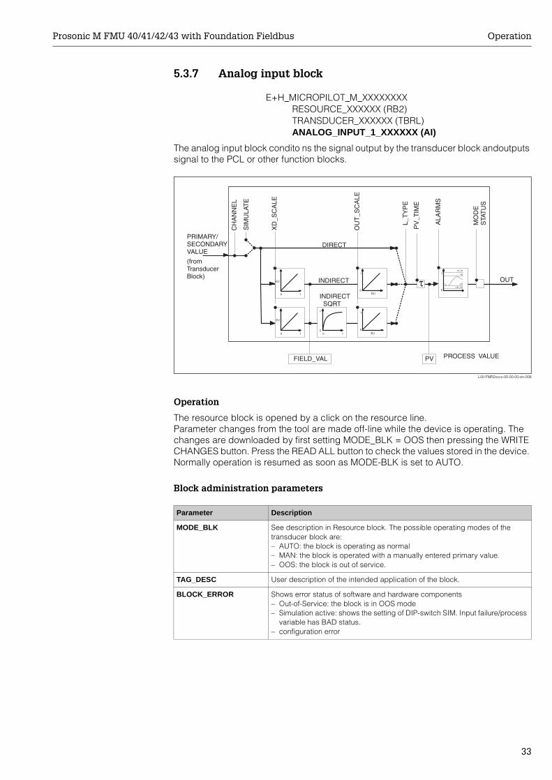
5.3.7 Analog input block
The analog input block condito ns the signal output by the transducer block andoutputs signal to the PCL or other function blocks.
L00-FMR2xxxx-05-00-00-en-008
Operation
The resource block is opened by a click on the resource line.Parameter changes from the tool are made off-line while the device is operating. The changes are downloaded by first setting MODE_BLK = OOS then pressing the WRITE CHANGES button. Press the READ ALL button to check the values stored in the device. Normally operation is resumed as soon as MODE-BLK is set to AUTO.
Block administration parameters
E+H_MICROPILOT_M_XXXXXXXXRESOURCE_XXXXXX (RB2)TRANSDUCER_XXXXXX (TBRL)ANALOG_INPUT_1_XXXXXX (AI)
Parameter Description
MODE_BLK See description in Resource block. The possible operating modes of the transducer block are:– AUTO: the block is operating as normal– MAN: the block is operated with a manually entered primary value.– OOS: the block is out of service.
TAG_DESC User description of the intended application of the block.
BLOCK_ERROR Shows error status of software and hardware components– Out-of-Service: the block is in OOS mode– Simulation active: shows the setting of DIP-switch SIM. Input failure/process
variable has BAD status.– configuration error
Operation Prosonic M FMU 40/41/42/43 with Foundation Fieldbus
34
Output values
Scaling parameters
The relationship between the output values and scaling paramaters for the Micropilot M is as follows:
The L_TYPE parameter influences the signal conversion:• Direct:
• Indirect:
• Indirect square root:
Parameter Description
PV Either the primary/secondary transducer block value used to execute the block or a process value associated with it. Comprises value and status.
OUT The primary value output as a result of executing the analog input block. Com-prises value and status.
FIELD_VALUE Raw value of field device in % of PV range with a status reflecting the transdu-cer condition before signal characterisation L_Type or filtering V_TIME. Com-prises value and status.
Parameter Description
CHANNEL Selects the measured value to be input to the analogue input block– 0 = no channel defined– 1 = primary value: measured level/volume– 2 = secondary value: measured distance
XD_SCALE Scales the transducer block value in the required engineering units (EU).
OUT_SCALE Scales the output value in the required engineering units (EU).
L_TYPE Sets the linearization type:– DIRECT: the transducer block value bypasses the scaling functions– INDIRECT:the transducer block value is fed through the linear scaling func-
tions– INDIRECT SQRT: the transducer block value is fed through the square root
scaling functions
MIN_SCALE_XDMAX_SCALE_XDMIN_SCALE_XDVALUE_CHANNEL
100VAL_FIELD−−×=
PV = CHANNEL_VALUE
( ) MIN_SCALE_OUTMIN_SCALE_OUTMAX_SCALE_OUT100
VALUE_FIELDPV +−×=
( ) MIN_SCALE_OUTMIN_SCALE_OUTMAX_SCALE_OUT100
VALUE_FIELDPV +−×=
Prosonic M FMU 40/41/42/43 with Foundation Fieldbus Operation
35
Output response parameters
Alarm parameters
Alarm priorities
Alarm status
Parameter Description
LOW_CUT Not relevant to level measurement!Determines a threshold for square root linearization below which the output value is set to zero.
PV_FTIME Sets the time constant for the output value.
Parameter Description
ACK_OPTION Sets the way in which alarms and warnings are to be acknowledged.
ALARM_HYS Sets the hysteresis (in output engineering units) for all configured alarms.A hysteresis of e.g. 2% on a HI_HI_LIMIT of 95% would cause the alarm to activate when the level reaches 95% and to deactivate when the level drops below 93%.A hysteresis of e.g. 2% on a LO_LO_LIMIT of 5% would cause the alarm to activate when the level drops below 5% and to deactivate when the level rises to 7%.
HI_HI_PRI The priority (1 – 15) of the HI_HI alarm
HI_HI_LIM Sets the HI_HI alarm limit in output engineering units
HI_PRI The priority (1 – 15) of the HI alarm
HI_LIM Sets the HI warning limit in output engineering units
LO_PRI The priority (1 – 15) of the LO alarm
LO_LIM Sets the LO warning limit in output engineering units
LO_LO_PRI The priority (1 – 15) of the LO_LO alarm
LO_LO_LIM Sets the LO_LO alarm limit in output engineering units
Parameter Description
0 Alarm is suppressed
1 Recognised by the system but not reported
2 Reported to the operator, but does not require his attention
3 - 7 Advisroy alarms of increasing priority
8 - 15 Critical alarms of increasing priority
Parameter Description
HI_HI_ALM The status of the HI_HI alarm
HI_ALM The status of the HI alarm
LO_ALM The status of the LO alarm
LO_LO_ALM The status of the LO_LO alarm

Operation Prosonic M FMU 40/41/42/43 with Foundation Fieldbus
36
Simulation
The SIMULATE parameter allows the transducer block output value to be simulated, provided simulation has also been enabled at the device DIP switch. The simulation must be enabled, a value and/or status entered and the block must be in AUTO mode. During simulation the transducer output value is substituted by the simulated value.A simulation is also possible by switching MODE_BLK to "MAN" and entering a value for OUT.
Parameter Description
SIMULATE Enables, sets and displays a simulated value, options:– enable/disable– simulated value– output value
Prosonic M FMU 40/41/42/43 with Foundation Fieldbus Operation
37
5.3.8 Checklist for commissioningThe following checklist refers to the configuration via the NI-Fieldbus configurator. In general, the operation is rather similar for other network design tools.
1. Configure the network and integrate the device.– Identify the device by means of the device ID and serial number.– If appropriate, assign a new PD_TAG.
2. Configure the resource block.– Check the position of the hardware switch in WRITE_LOCK– If "locked" is displayed, change the position of the DIP-switch.– If appropriate, change the block tag (right-hand click on tree).– Set MODE_BLK_TARGET to Out-of-Service.– Reset the device to factory values by using the function RESTART => Defaults
(this function may also be available with a right-hand click on the device name)– If appropriate, assign a tag description (TAG_DESC).– Set MODE_BLK_TARGET to Auto.
3. Configure the transducer block.– If appropriate, change the block tag (right-hand click on tree).– Set MODE_BLK_TARGET to Out-of-Service.– If appropriate, assign a tag description (TAG_DESC)– Configure the device as described in Chapter 6.4.– Set MODE_BLK_TARGET to Auto.
4. Configure the analog input block. – If appropriate, change the block tag (right-hand click on tree).– Set MODE_BLK_TARGET to Out-of-Service.– If appropriate, assign a tag description (TAG_DESC).– Set Channel to measured value or distance.– Set L_TYPE to "DIRECT" if the OUT value is to be in technical units e.g. ft to
"INDIRECT" if the OUT value is to be scaled.– Set the desired output damping in PV_TIME.– If appropriate, set the advisory and critical alarms.– Set MODE_BLK_TARGET to Auto.
5. Link the function blocks in the function block editor.
6. Download the configuration (menu configure).
7. If appropriate, check the configuration by using the SIMULATE function.
Operation Prosonic M FMU 40/41/42/43 with Foundation Fieldbus
38
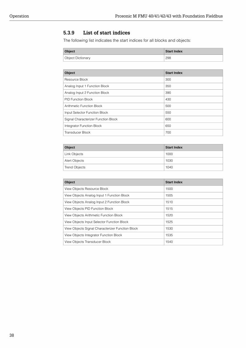
5.3.9 List of start indicesThe following list indicates the start indices for all blocks and objects:
Object Start Index
Object Dictionary 298
Object Start Index
Resource Block 300
Analog Input 1 Function Block 350
Analog Input 2 Function Block 390
PID Function Block 430
Arithmetic Function Block 500
Input Selector Function Block 550
Signal Characterizer Function Block 600
Integrator Function Block 650
Transducer Block 700
Object Start Index
Link Objects 1000
Alert Objects 1030
Trend Objects 1040
Object Start Index
View Objects Resource Block 1500
View Objects Analog Input 1 Function Block 1505
View Objects Analog Input 2 Function Block 1510
View Objects PID Function Block 1515
View Objects Arithmetic Function Block 1520
View Objects Input Selector Function Block 1525
View Objects Signal Characterizer Function Block 1530
View Objects Integrator Function Block 1535
View Objects Transducer Block 1540
Prosonic M FMU 40/41/42/43 with Foundation Fieldbus Operation
39
5.3.10 Parameter access via ToF ToolThe ToF Tool is a graphical operation software for instruments from Endress+Hauser. It is used to support commissioning, securing of data, signal analysis and documentation of the instruments. It is compatible with the following operating systems: Win95, Win98, WinNT4.0 and Win2000.
The ToF Tool supports the following functions:• Online configuration of transmitters• Signal analysis via envelope curve• Loading and saving of instrument data (Upload/Download)• Documentation of measuring point
! Note! The parameters of the Analog-Input block are presently not accessible via ToF Tool.
! Note! ToF-Tool operation of the Prosonic M is not possible via Foundation Fieldbus. Instead, the PC or Laptop must be connected via the interface FXA 193 to the service adapter, to which normally the display is connected.
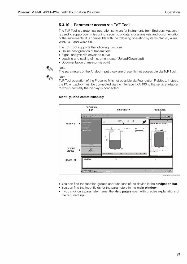
Menu-guided commissioning
L00-FMU4xxxx-19-00-00-en-003
• You can find the function groups and functions of the device in the navigation bar.• You can find the input fields for the parameters in the main window.• If you click on a parameter name, the Help pages open with precise explanations of
the required input.
Operation Prosonic M FMU 40/41/42/43 with Foundation Fieldbus
40
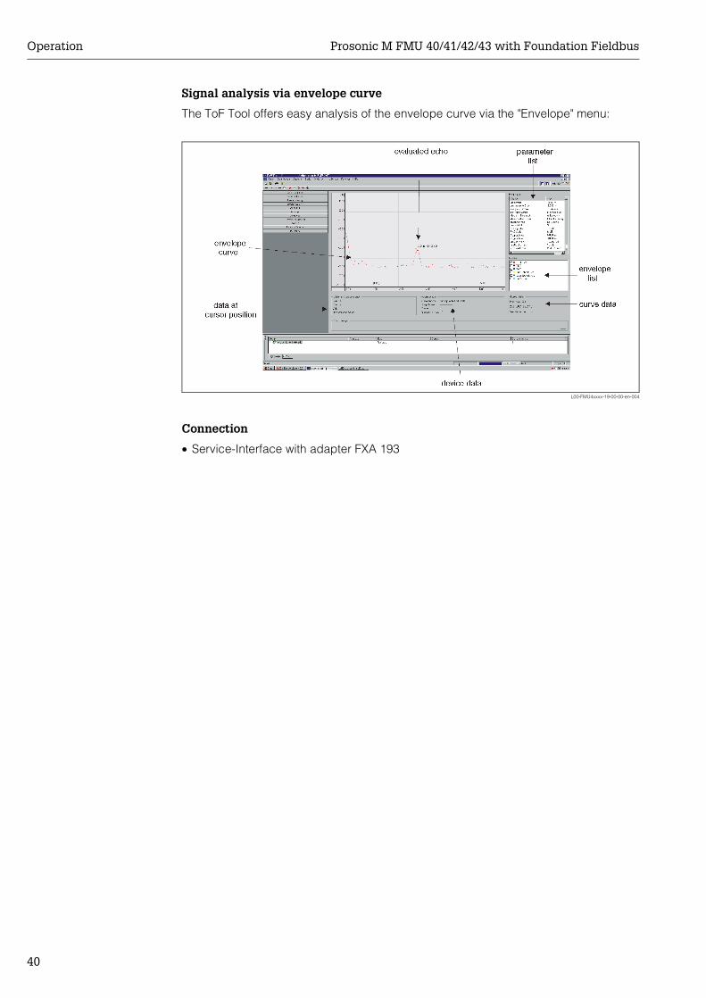
Signal analysis via envelope curve
The ToF Tool offers easy analysis of the envelope curve via the "Envelope" menu:
L00-FMU4xxxx-19-00-00-en-004
Connection
• Service-Interface with adapter FXA 193
Prosonic M FMU 40/41/42/43 with Foundation Fieldbus Operation
41
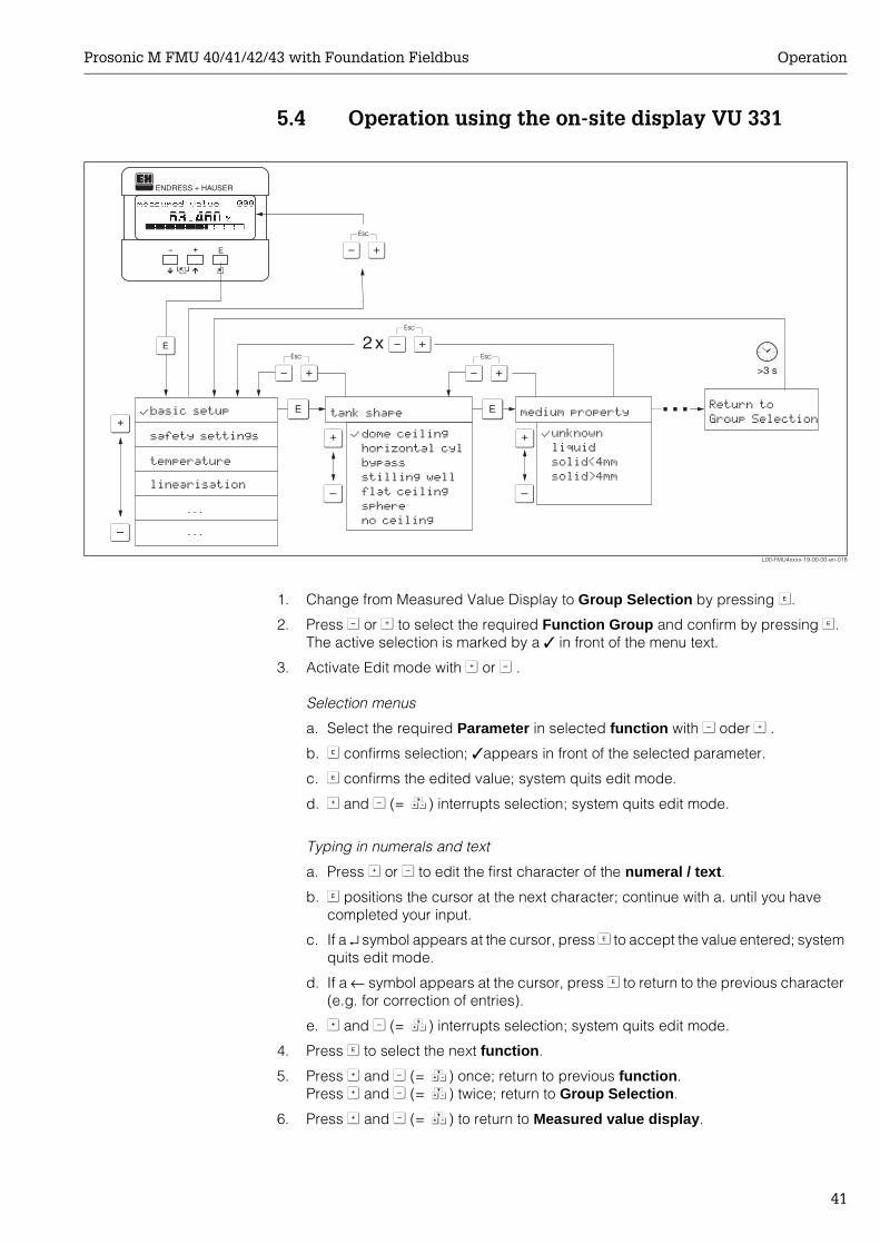
5.4 Operation using the on-site display VU 331
L00-FMU4xxxx-19-00-00-en-018
1. Change from Measured Value Display to Group Selection by pressing F.
2. Press S or O to select the required Function Group and confirm by pressing F.The active selection is marked by a ✓ in front of the menu text.
3. Activate Edit mode with O or S .
Selection menus
a. Select the required Parameter in selected function with S oder O .
b. F confirms selection; ✓appears in front of the selected parameter.
c. F confirms the edited value; system quits edit mode.
d. O and S (= Q) interrupts selection; system quits edit mode.
Typing in numerals and text
a. Press O or S to edit the first character of the numeral / text.
b. F positions the cursor at the next character; continue with a. until you have completed your input.
c. If a ↵ symbol appears at the cursor, press F to accept the value entered; system quits edit mode.
d. If a ← symbol appears at the cursor, press F to return to the previous character (e.g. for correction of entries).
e. O and S (= Q) interrupts selection; system quits edit mode.
4. Press F to select the next function.
5. Press O and S (= Q) once; return to previous function.Press O and S (= Q) twice; return to Group Selection.
6. Press O and S (= Q) to return to Measured value display.
X XX
X
S
S S
OO O
F F
>3 s
F
ENDRESS + HAUSER
E+–
...
2x
...
...
�������
���
������
������
���������
��������������� �� ����
������ �����
�����������
���� ����
����� ���
���������
��!�������
����
������
��������
� ���
�������
��������������
Operation Prosonic M FMU 40/41/42/43 with Foundation Fieldbus
42
5.5 Lock/unlock configuration
5.5.1 Software security lockingEnter a number ≠ 2457 in the "unlock parameter" (0A4) function in the "diagnostics" (0A) function group.The symbol appears on the display. Inputs are no longer possible.
If you try to change a parameter, the device jumps to the "unlock parameter" (0A4) function. Enter "2457"Now change the parameters.
5.5.2 Hardware security lockingPress S, O and F simultaneously.Inputs are no longer possible.
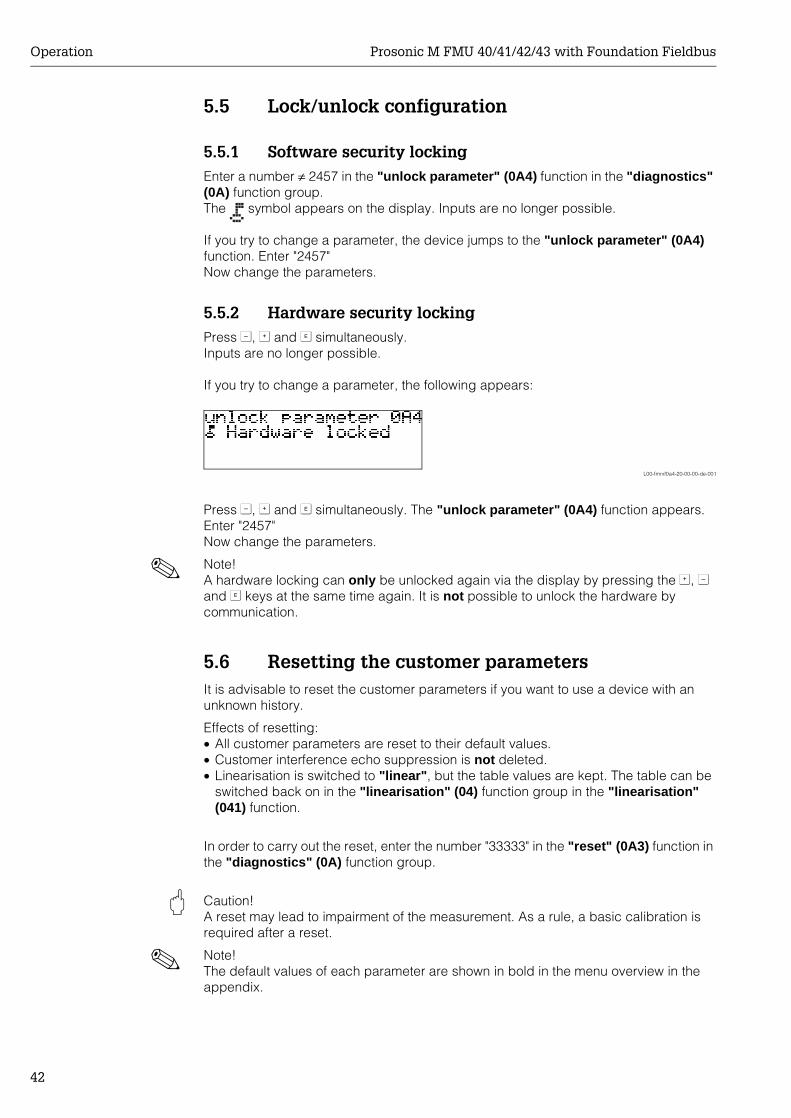
If you try to change a parameter, the following appears:
L00-fmrxf0a4-20-00-00-de-001
Press S, O and F simultaneously. The "unlock parameter" (0A4) function appears.Enter "2457"Now change the parameters.
! Note! A hardware locking can only be unlocked again via the display by pressing the O, S and F keys at the same time again. It is not possible to unlock the hardware by communication.
5.6 Resetting the customer parametersIt is advisable to reset the customer parameters if you want to use a device with an unknown history.
Effects of resetting:• All customer parameters are reset to their default values.• Customer interference echo suppression is not deleted.• Linearisation is switched to "linear", but the table values are kept. The table can be
switched back on in the "linearisation" (04) function group in the "linearisation" (041) function.
In order to carry out the reset, enter the number "33333" in the "reset" (0A3) function in the "diagnostics" (0A) function group.
" Caution! A reset may lead to impairment of the measurement. As a rule, a basic calibration is required after a reset.
! Note! The default values of each parameter are shown in bold in the menu overview in the appendix.
Prosonic M FMU 40/41/42/43 with Foundation Fieldbus Operation
43
5.7 Resetting an interference echo suppression (tank map)
It is always advisable to reset the interference echo suppression (tank mapping) when:• a device with an unknown history is used• an incorrect suppression was input.
Proceed as follows:
1. Switch to the "extended calibr." (05) function group and to the "selection" (050) function.
2. Select "extended map."
3. Then proceed to the "cust. tank map" (055) function.
4. Select– "reset", to delete (reset) the existing interference echo suppression.– "inactive" to deactivate an existing interference echo suppression. The
suppression remains saved.– "active" to reactivate an existing interference echo suppression.
Commissioning Prosonic M FMU 40/41/42/43 with Foundation Fieldbus
44
6 CommissioningCommission the Prosonic M in the following stages:• Installation check• Power-up device• Basic calibration• Measuring signal check using the envelope curve
The chapter describes the commissioning process using the on-site display. Commissioning using ToF Tool is identical. Access to the device functions using ToF Tool is described on Page 21. You can find detailed information in the Tof Tool operating instructions (BA 224F/00/en) on the supplied CD-ROM.
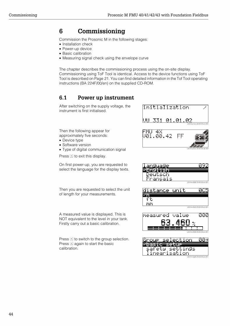
6.1 Power up instrumentAfter switching on the supply voltage, the instrument is first initialised.
L00-fmp-fxxx-20-00-00-en-003
Then the following appear for approximately five seconds:• Device type• Software version• Type of digital communication signal
Press F to exit this display.
L00-fmuxfxxx-20-00-00-de-002
On first power-up, you are requested to select the language for the display texts.
L00-fmrxf092-20-00-00-en-001
Then you are requested to select the unit of length for your measurements.
L00-fmrxf0c5-20-00-00-en-001
A measured value is displayed. This is NOT equivalent to the level in your tank. Firstly carry out a basic calibration.
L00-fmrxf000-20-00-00-en-001
Press F to switch to the group selection.Press F again to start the basic calibration.
L00-fmrxfg00-20-00-00-en-001
Prosonic M FMU 40/41/42/43 with Foundation Fieldbus Commissioning
45
6.2 Basic calibrationThe "Basic setup" (00) function group lists all the functions which are required for a standard measurement task to commission the Prosonic M. When you have completed your input for a function, the next function appears automatically. In this way, you are guided through the complete calibration.
6.2.1 Measuring point settings
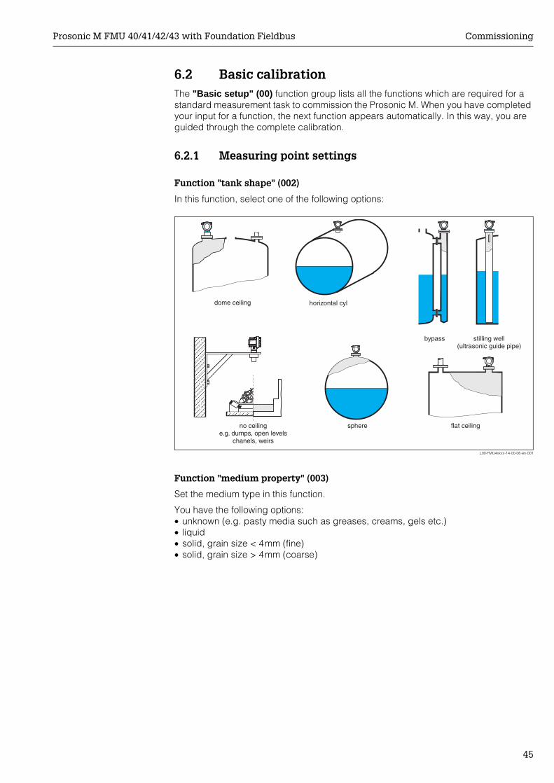
Function "tank shape" (002)
In this function, select one of the following options:
L00-FMU4xxxx-14-00-06-en-001
Function "medium property" (003)
Set the medium type in this function.
You have the following options:• unknown (e.g. pasty media such as greases, creams, gels etc.)• liquid• solid, grain size < 4mm (fine)• solid, grain size > 4mm (coarse)
ENDRESS+HAUSERProsonic M
dome ceiling
flat ceilingsphere
horizontal cyl
bypass stilling well(ultrasonic guide pipe)
no ceilinge.g. dumps, open levels
chanels, weirs
Commissioning Prosonic M FMU 40/41/42/43 with Foundation Fieldbus
46
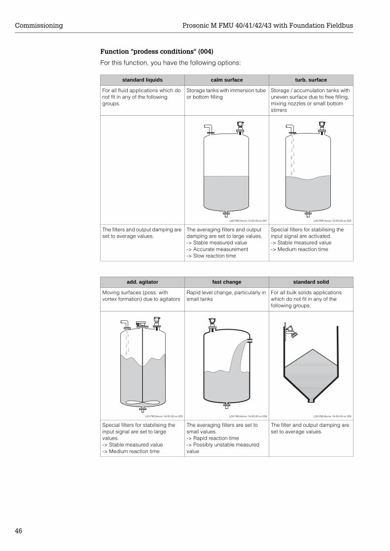
Function "prodess conditions" (004)
For this function, you have the following options:
standard liquids calm surface turb. surface
For all fluid applications which do not fit in any of the following groups.
Storage tanks with immersion tube or bottom filling
Storage / accumulation tanks with uneven surface due to free filling, mixing nozzles or small bottom stirrers
L00-FMU4xxxx-14-00-00-xx-001 L00-FMU4xxxx-14-00-00-xx-002
The filters and output damping are set to average values.
The averaging filters and output damping are set to large values.-> Stable measured value-> Accurate measurement-> Slow reaction time
Special filters for stabilising the input signal are activated.-> Stable measured value-> Medium reaction time
add. agitator fast change standard solid
Moving surfaces (poss. with vortex formation) due to agitators
Rapid level change, particularly in small tanks
For all bulk solids applications which do not fit in any of the following groups.
L00-FMU4xxxx-14-00-00-xx-003 L00-FMU4xxxx-14-00-00-xx-004 L00-FMU4xxxx-14-00-00-xx-006
Special filters for stabilising the input signal are set to large values.-> Stable measured value-> Medium reaction time
The averaging filters are set to small values.-> Rapid reaction time-> Possibly unstable measured value
The filter and output damping are set to average values.
Prosonic M FMU 40/41/42/43 with Foundation Fieldbus Commissioning
47
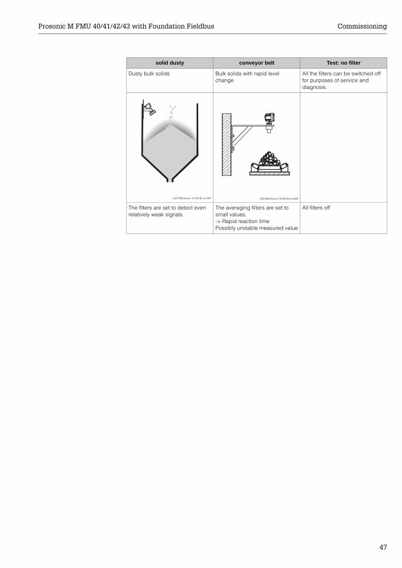
solid dusty conveyor belt Test: no filter
Dusty bulk solids Bulk solids with rapid level change
All the filters can be switched off for purposes of service and diagnosis.
L00-FMU4xxxx-14-00-00-xx-007 L00-FMU4xxxx-14-00-00-xx-005
The filters are set to detect even relatively weak signals.
The averaging filters are set to small values.-> Rapid reaction timePossibly unstable measured value
All filters off
ENDRESS+HAUSERProsonic M
Commissioning Prosonic M FMU 40/41/42/43 with Foundation Fieldbus
48
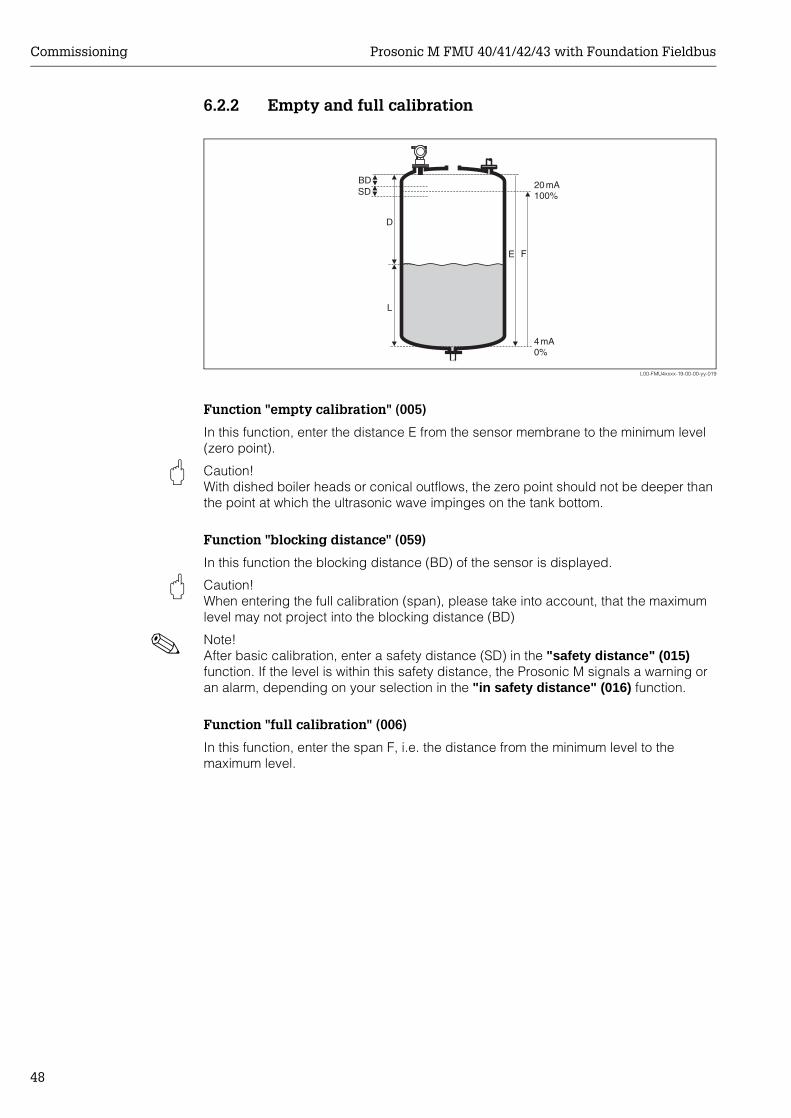
6.2.2 Empty and full calibration
L00-FMU4xxxx-19-00-00-yy-019
Function "empty calibration" (005)
In this function, enter the distance E from the sensor membrane to the minimum level (zero point).
" Caution! With dished boiler heads or conical outflows, the zero point should not be deeper than the point at which the ultrasonic wave impinges on the tank bottom.
Function "blocking distance" (059)
In this function the blocking distance (BD) of the sensor is displayed.
" Caution! When entering the full calibration (span), please take into account, that the maximum level may not project into the blocking distance (BD)
! Note! After basic calibration, enter a safety distance (SD) in the "safety distance" (015) function. If the level is within this safety distance, the Prosonic M signals a warning or an alarm, depending on your selection in the "in safety distance" (016) function.
Function "full calibration" (006)
In this function, enter the span F, i.e. the distance from the minimum level to the maximum level.
20mA100%
4mA0%
D
L
FE
BDSD
Prosonic M FMU 40/41/42/43 with Foundation Fieldbus Commissioning
49
6.2.3 Interference echo suppression (tank mapping)
Function "dist./measured value" (008)
In the "dist./meas.value" (008) function, the measured distance D from the sensor membrane to the product surface is displayed together with level L. Check these values.
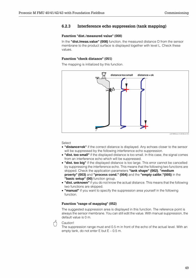
Function "check distance" (051)
The mapping is initialized by this function.
L00-FMR2xxxx-14-00-06-en-010
Select• "distance=ok" if the correct distance is displayed. Any echoes closer to the sensor
will be suppressed by the following interference echo suppression.• "dist. too small" if the displayed distance is too small. In this case, the signal comes
from an interference echo which will be suppressed.• "dist. too big" if the displayed distance is too large. This error cannot be cancelled
by suppressing the interference echo. This means that the following two functions are skipped. Check the application parameters "tank shape" (002), "medium proerty" (003) and "process cond." (004) and the "empty calibr."(005) in the "basic setup" (00) function group.
• "dist. unknown" if you do not know the actual distance. This means that the following two functions are skipped.
• "manual" if you want to specify the suppression area yourself in the following function.
Function "range of mapping" (052)
The suggested suppression area is displayed in this function. The reference point is always the sensor membrane. You can still edit the value. With manual suppression, the default value is 0 m.
" Caution! The suppression range must end 0.5 m in front of the echo of the actual level. With an empty tank, do not enter E but E – 0.5 m.
Commissioning Prosonic M FMU 40/41/42/43 with Foundation Fieldbus
50
Function "start mapping" (053)
You have the following options for this function:• off: Nothing is suppressed.• on: Starts suppression.
! Note! If a mapping already exists, it will be overwritten up to the distance specified in the "range of mapping" (052) function. Beyond this distance the existing mapping remains unchanged.
Function dist./measured value (008)
After suppression, the measured distance D from the sensor membrane to the product surface is displayed together with the level. Check that the values correspond to the actual level and/or the actual distance.
The following cases may occur:• Distance correct – Level correct -> End of basic calibration• Distance incorrect – Level incorrect -> An additional interference echo suppression
must be carried out. Go back to the "check distance" (051) function.• Distance correct – Level incorrect -> Check the value of the "empty calibr." (005)
function.
Rücksprung zur Gruppenauswahl
Nach der Störechoausblendung ist der Grundabgleich beendet und das Gerät springt automatisch in die Gruppenauswahl zurück.
6.3 Envelope curveAfter the basic setup, an evaluation of the measurement with the aid of the envelope curve ("envelope curve" (0E) function group) is recommended.
6.3.1 Funxtion "plot settings" (0E1)In this function, select whether you want to display• just the envelope curve• The envelope curve and the echo evaluation line FAC• The envelope curve and interference echo suppression (map)
! Note! The FAC and the interference echo suppression (map) are explained in BA 240F "Prosonic M - Description of Instrument Functions"
6.3.2 Function "recording curve" (0E2)In this function, specify whether you want to display• an individual envelope curve• The current envelope curve, with cyclical refreshment.
Prosonic M FMU 40/41/42/43 with Foundation Fieldbus Commissioning
51
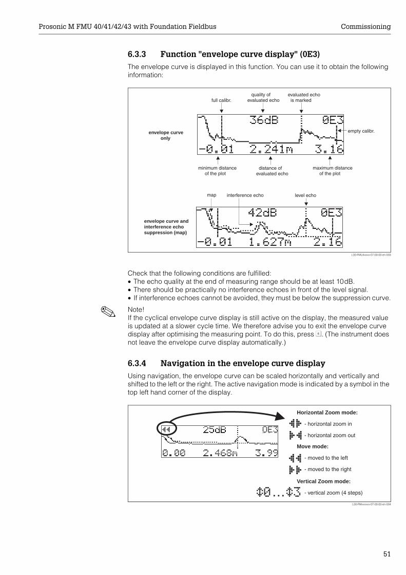
6.3.3 Function "envelope curve display" (0E3)The envelope curve is displayed in this function. You can use it to obtain the following information:
L00-FMU4xxxx-07-00-00-en-003
Check that the following conditions are fulfilled:• The echo quality at the end of measuring range should be at least 10dB.• There should be practically no interference echoes in front of the level signal.• If interference echoes cannot be avoided, they must be below the suppression curve.
! Note! If the cyclical envelope curve display is still active on the display, the measured value is updated at a slower cycle time. We therefore advise you to exit the envelope curve display after optimising the measuring point. To do this, press F. (The instrument does not leave the envelope curve display automatically.)
6.3.4 Navigation in the envelope curve displayUsing navigation, the envelope curve can be scaled horizontally and vertically and shifted to the left or the right. The active navigation mode is indicated by a symbol in the top left hand corner of the display.
L00-FMxxxxxx-07-00-00-en-004
minimum distanceof the plot
maximum distanceof the plot
distance ofevaluated echo
interference echo
evaluated echois marked
quality ofevaluated echo
empty calibr.envelope curveonly
envelope curve andinterference echosuppression (map)
level echomap
full calibr.
…
"#$
Move mode:
- m
-
oved to the left
moved to the right
Horizontal Zoom mode:
- h
-
orizontal zoom in
horizontal zoom out
Vertical Zoom mode:
- vertical zoom (4 steps)
Commissioning Prosonic M FMU 40/41/42/43 with Foundation Fieldbus
52
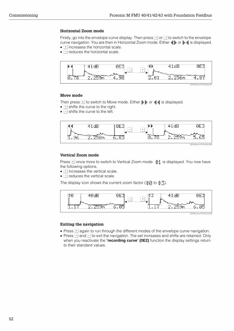
Horizontal Zoom mode
Firstly, go into the envelope curve display. Then press O or S to switch to the envelope curve navigation. You are then in Horizontal Zoom mode. Either or is displayed.• O increases the horizontal scale.• S reduces the horizontal scale.
L00-FMxxxxxx-07-00-00-yy-007
Move mode
Then press F to switch to Move mode. Either or is displayed.• O shifts the curve to the right.• S shifts the curve to the left.
L00-FMxxxxxx-07-00-00-yy-008
Vertical Zoom mode
Press F once more to switch to Vertical Zoom mode. is displayed. You now have the following options.• O increases the vertical scale.• S reduces the vertical scale.
The display icon shows the current zoom factor ( to ).
L00-FMxxxxxx-07-00-00-yy-009
Exiting the navigation
• Press F again to run through the different modes of the envelope curve navigation.• Press O and S to exit the navigation. The set increases and shifts are retained. Only
when you reactivate the "recording curve" (0E2) function the display settings return to their standard values.
OS
OS
OS
Prosonic M FMU 40/41/42/43 with Foundation Fieldbus Troubleshooting
53
7 Troubleshooting
7.1 System error messages
7.1.1 Current errorErrors which the Prosonic M detects during commissioning or operation are displayed:
• In the "measured value" (000) function• In the "diagnostics" (0A) function group in the "present error" (0A0) function
Only the highest priority error is displayed; in the case of multiple errors, you can scroll between the different error messages by pressing O or S.
• by the status of the main value
7.1.2 Last errorThe last error is displayed in the "diagnostics" (0A) function group in the "previous error" (0A1) function. This display can be deleted in the "clear last error" (0A2) function.
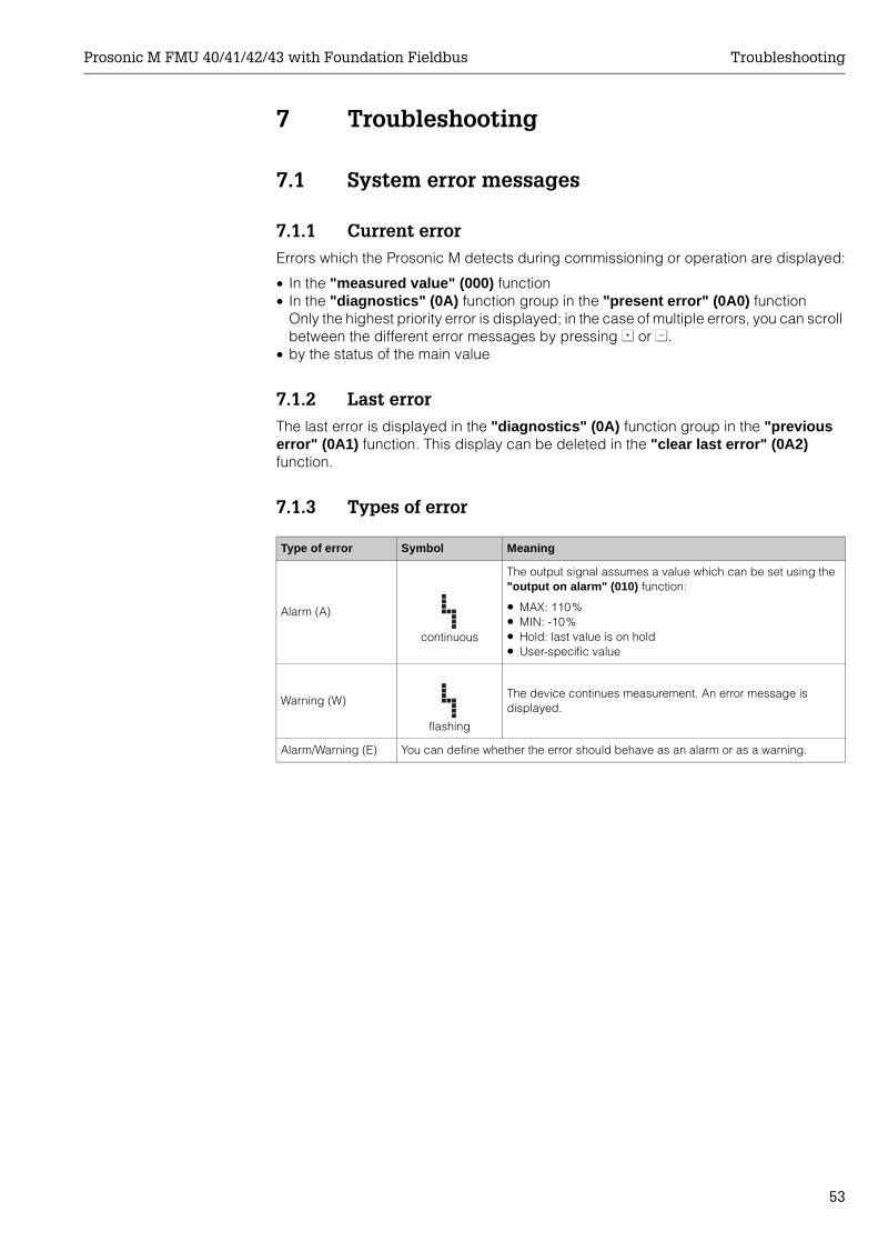
7.1.3 Types of error
Type of error Symbol Meaning
Alarm (A)
continuous
The output signal assumes a value which can be set using the "output on alarm" (010) function:
• MAX: 110%• MIN: -10%• Hold: last value is on hold• User-specific value
Warning (W)
flashing
The device continues measurement. An error message is displayed.
Alarm/Warning (E) You can define whether the error should behave as an alarm or as a warning.
Troubleshooting Prosonic M FMU 40/41/42/43 with Foundation Fieldbus
54
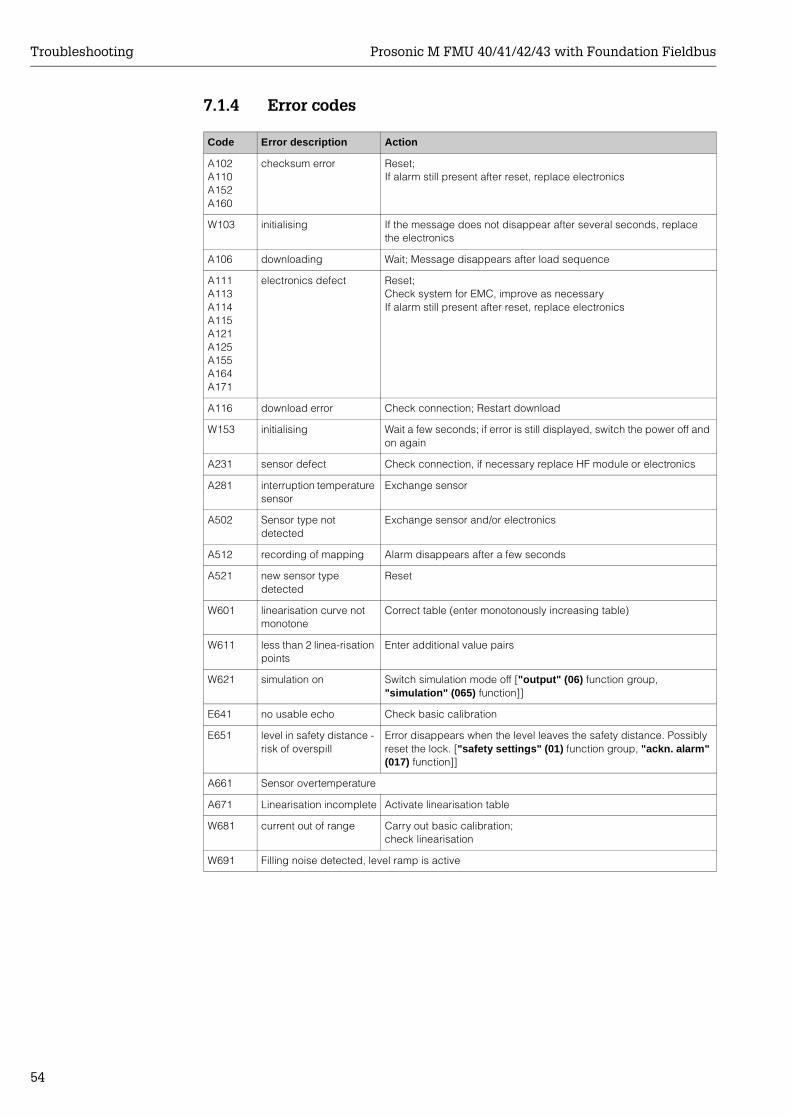
7.1.4 Error codes
Code Error description Action
A102A110A152A160
checksum error Reset;If alarm still present after reset, replace electronics
W103 initialising If the message does not disappear after several seconds, replace the electronics
A106 downloading Wait; Message disappears after load sequence
A111A113A114A115A121A125A155A164A171
electronics defect Reset;Check system for EMC, improve as necessaryIf alarm still present after reset, replace electronics
A116 download error Check connection; Restart download
W153 initialising Wait a few seconds; if error is still displayed, switch the power off and on again
A231 sensor defect Check connection, if necessary replace HF module or electronics
A281 interruption temperature sensor
Exchange sensor
A502 Sensor type not detected
Exchange sensor and/or electronics
A512 recording of mapping Alarm disappears after a few seconds
A521 new sensor type detected
Reset
W601 linearisation curve not monotone
Correct table (enter monotonously increasing table)
W611 less than 2 linea-risation points
Enter additional value pairs
W621 simulation on Switch simulation mode off ["output" (06) function group, "simulation" (065) function]]
E641 no usable echo Check basic calibration
E651 level in safety distance - risk of overspill
Error disappears when the level leaves the safety distance. Possibly reset the lock. ["safety settings" (01) function group, "ackn. alarm" (017) function]]
A661 Sensor overtemperature
A671 Linearisation incomplete Activate linearisation table
W681 current out of range Carry out basic calibration;check linearisation
W691 Filling noise detected, level ramp is active
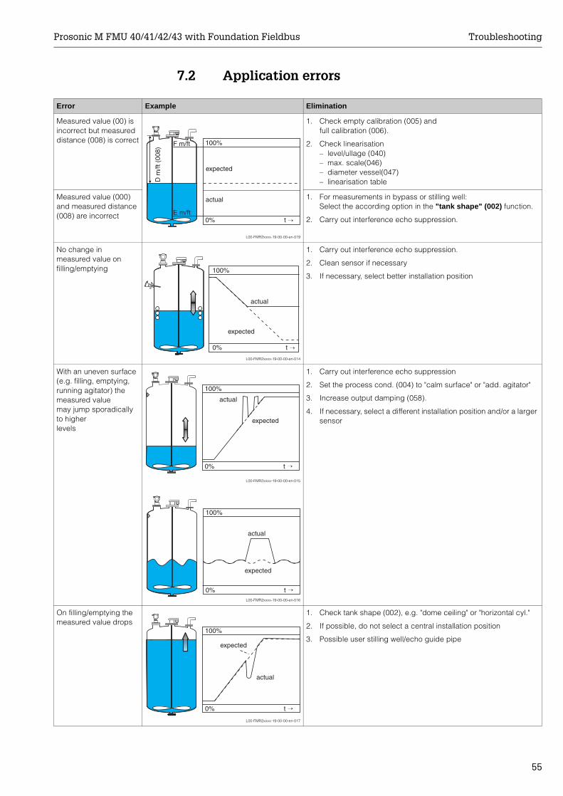
Prosonic M FMU 40/41/42/43 with Foundation Fieldbus Troubleshooting
55
7.2 Application errors
Error Example Elimination
Measured value (00) is incorrect but measured distance (008) is correct
L00-FMR2xxxx-19-00-00-en-019
1. Check empty calibration (005) andfull calibration (006).
2. Check linearisation– level/ullage (040)– max. scale(046)– diameter vessel(047)– linearisation table
Measured value (000) and measured distance (008) are incorrect
1. For measurements in bypass or stilling well: Select the according option in the "tank shape" (002) function.
2. Carry out interference echo suppression.
No change in measured value on filling/emptying
L00-FMR2xxxx-19-00-00-en-014
1. Carry out interference echo suppression.
2. Clean sensor if necessary
3. If necessary, select better installation position
With an uneven surface (e.g. filling, emptying, running agitator) the measured valuemay jump sporadically to higher levels
L00-FMR2xxxx-19-00-00-en-015
L00-FMR2xxxx-19-00-00-en-016
1. Carry out interference echo suppression
2. Set the process cond. (004) to "calm surface" or "add. agitator"
3. Increase output damping (058).
4. If necessary, select a different installation position and/or a larger sensor
On filling/emptying the measured value drops
L00-FMR2xxxx-19-00-00-en-017
1. Check tank shape (002), e.g. "dome ceiling" or "horizontal cyl."
2. If possible, do not select a central installation position
3. Possible user stilling well/echo guide pipe
100%F m/ft
E m/ft0% t →
D m
/ft (
008)
actual
expected
100%
0% t →
actual
expected
100%
0% t →
actual
expected
100%
0% t →
actual
expected
100%
0% t →
actual
expected
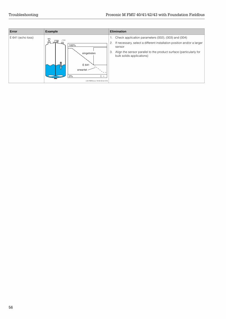
Troubleshooting Prosonic M FMU 40/41/42/43 with Foundation Fieldbus
56
E 641 (echo loss)
L00-FMR2xxxx-19-00-00-en-018
1. Check application parameters (002), (003) and (004)
2. If necessary, select a different installation position and/or a larger sensor
3. Align the sensor parallel to the product surface (particularly for bulk solids applications)
Error Example Elimination
100%
E 641
0% t →
eingetreten
erwartet
Prosonic M FMU 40/41/42/43 with Foundation Fieldbus Maintenance and repairs
57
8 Maintenance and repairs
8.1 Exterior cleaningWhen cleaning the exterior, always use cleaning agents that do not attack the surface of the housing and the seals.
8.2 RepairsThe Endress+Hauser repair concept assumes that the measuring devices have a modular design and that customers are able to undertake repairs themselves.Spare parts are contained in suitable kits. They contain the related replacement instructions.All the spare parts kits which you can order from Endress+Hauser for repairs are listed with their order numbers in the section "Spare parts".For more information on service and spare parts, contact the Service Department at Endress+Hauser.
8.3 Repairs to Ex-approved devicesWhen carrying out repairs to Ex-approved devices, please note the following:• Repairs to Ex-approved devices may only be carried out by trained personnel or by
Endress+Hauser Service.• Comply with the prevailing standards, national Ex-area regulations, safety instructions
(XA) and certificates.• Only use original spare parts from Endress+Hauser.• When ordering a spare part, please note the device designation on the nameplate.
Only replace parts with identical parts.• Carry out repairs according to the instructions. On completion of repairs, carry our the
specified routine test on the device.• Only Endress+Hauser Service may convert a certified device into a different certified
variant.• Document all repair work and conversions.
8.4 ReplacementAfter a complete instrument or electronic module has been replaced, the parameters can be downloaded into the instrument again via the communication interface. Prerequisite to this is that the data were uploaded to the PC beforehand using the ToF Tool / Commuwin II. Measurement can continue without having to carry out a new setup. Only a linearisation and a tank map (interference echo suppression) have to be recorded again.

Maintenance and repairs Prosonic M FMU 40/41/42/43 with Foundation Fieldbus
58
8.5 Spare parts (housing type F12)
L00-FMU4xxxx-09-00-00-en-001
Ma
de
in G
erm
any
Ma
ulb
urg
Ma
de
in G
erm
any
Ma
ulb
urg
12
34
Housing F12standard, complete pre-mounted, incl. nameplate,cable gland and Teflon filter543 120 - 0022 G ½" cable gland543 120 - 0023 NPT ½"543 120 - 0024 M20 x 1.5
cable glandcable gland
5200 1992 M12 PROFIBUS PA plug5200 8556 7/8 UNC Fieldbus Foundation plug5201 3348 4-wire, G ½" cable gland5201 3350 4-wire M20 x 1,5 cable gland
Hood for terminalcompartment F12 cpl.5200 6026
Cover with O-ring for housing F12• with sight glas (not for ATEX II 1/2D)5200 5936
• without sight glas 517 391-0011
Control and display module VU 3315200 5585(cover with sight glas required)
Screw set
AB
Note the mountinginstructions!
535 720 - 9020consist of:1 stop screw M5x10; Pos.1 retaining screw M8x10; Pos.
Terminal
A
B
C
C
D
E
Retainingscrew
Stop screw
O-ring
O-ring
O-ring
O-ring
The spare parts listed are generally suitablefor use in Ex-devices
ENDRESS+HAUSER
ENDRESS+HAUSER
FMU 40
Sensor FMU 40complete with O-ringand nut 1.5"G1½" 5201 0509NPT1½" 5201 0507
Nut G1.5"5200 0599
D
FMU 41
Sensor FMU 41complete with O-ringand nut 2"G 2" 5201 0510NPT 2" 5201 0508
Nut G2"5200 0598
D
FMU 43
Gasket set
CDEFGH
5201 0526consist of:2 gaskets 25 x 20.5 x 2 FA; Pos.1 O-ring 49.21 x 3.53 EPDM; Pos.1 O-ring 113.9 x 3.53 NBR; Pos.1 O-ring 72.0 x 3.0 NBR; Pos.1 gasket 58 x 47 x 2 EPDM; Pos.1 gasket 68 x 59 x 2.5 EPDM; Pos.
Gasket G
Gasket H
Power supply for 4wire electronics10... 32 V DC 5201 330490...253 V AC 5201 3305
Terminal module with connection cable
Version PROFIBUS PA andFoundation Fieldbus 5201 2156
• Version HART (4pole) 5200 6197•
Electronic module complete
PROFIBUS PA 5201 0512Foundation Fieldbus 5201 2818
HART (2pole) 5201 0511HART (4pole) 5201 2819
in preparation
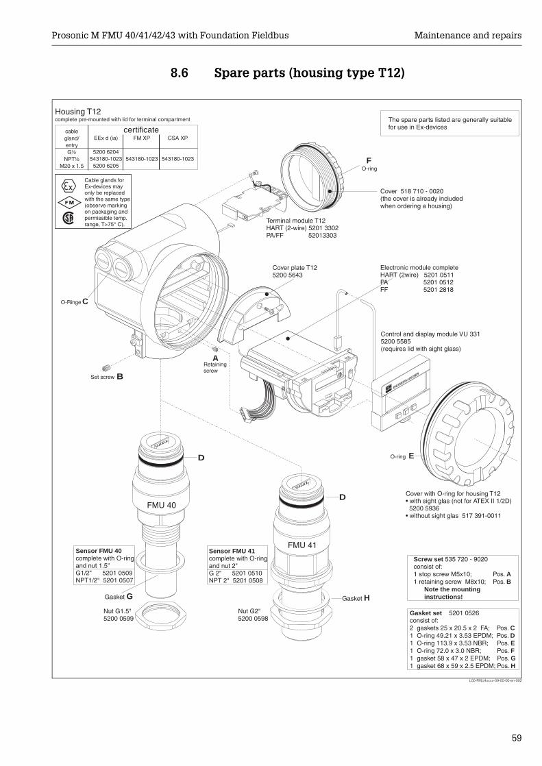
Prosonic M FMU 40/41/42/43 with Foundation Fieldbus Maintenance and repairs
59
8.6 Spare parts (housing type T12)
L00-FMU4xxxx-09-00-00-en-002
Housing T12complete pre-mounted with lid for terminal compartment
Cover with O-ring for housing T12• with sight glas (not for ATEX II 1/2D)
5200 5936• without sight glas 517 391-0011
Control and display module VU 3315200 5585(requires lid with sight glass)
Terminal module T12HART (2-wire) 5201 3302PA/FF 52013303
Cover plate T125200 5643
C
A
B
D
D
F
E
O-Ringe
O-ring
O-ring
Retainingscrew
Set screw
ENDRESS+HAUSER
ENDRESS+HAUSER
cablegland/entry
NPT½M20 x 1.5
G½
EEx d (ia)
5200 6204543180-1023
5200 6205
FM XP
543180-1023
CSA XP
543180-1023
certificate
FMU 40
FMU 41Sensor FMU 40complete with O-ringand nut 1.5"G1/2" 5201 0509NPT1/2" 5201 0507
Sensor FMU 41complete with O-ringand nut 2"G 2" 5201 0510NPT 2" 5201 0508
Nut G1.5"5200 0599
Nut G2"5200 0598
Screw set
AB
Note the mountinginstructions!
535 720 - 9020consist of:1 stop screw M5x10; Pos.1 retaining screw M8x10; Pos.
Gasket set
CDEFGH
5201 0526consist of:2 gaskets 25 x 20.5 x 2 FA; Pos.1 O-ring 49.21 x 3.53 EPDM; Pos.1 O-ring 113.9 x 3.53 NBR; Pos.1 O-ring 72.0 x 3.0 NBR; Pos.1 gasket 58 x 47 x 2 EPDM; Pos.1 gasket 68 x 59 x 2.5 EPDM; Pos.
Gasket G Gasket H
The spare parts listed are generally suitablefor use in Ex-devices
Cable glands forEx-devices mayonly be replacedwith the same type(observe markingon packaging andpermissible temp.range, T>75° C).
0
12
Electronic module cHART (2wire) 5201 0511PA 5201 0512FF 5201 2818
omplete
Cover 518 710 - 0020(the cover is already includedwhen ordering a housing)
Maintenance and repairs Prosonic M FMU 40/41/42/43 with Foundation Fieldbus
60
8.7 ReturnThe following procedures must be carried out before a transmitter is sent to Endress+Hauser e.g. for repair or calibration:• Remove all residue which may be present. Pay special attention to the gasket grooves
and crevices where fluid may be present. This is especially important if the fluid is dangerous to health, e.g. corrosive, poisonous, carcinogenic, radioactive, etc.
• Always enclose a duly completed "Declaration of contamination" form (a copy of the “Declaration of contamination” is included at the end of this operating manual). Only then can Endress +Hauser transport, examine and repair a returned device.
• Enclose special handling instructions if necessary, for example a safety data sheet as per EN 91/155/EEC.
Additionally specify:• An exact description of the application.• The chemical and physical characteristics of the product.• A short description of the error that occurred (specify error code if possible)• Operating time of the device.
8.8 DisposalIn case of disposal please seperate the different components according to their material consistence.
8.9 Software history
8.10 Contact addresses of Endress+HauserThe addresses of Endress+Hauser are given on the back cover of this operating manual. If you have any questions, please do not hesitate to contact your E+H representative.
Software version / date Changes to software Changes to documentation
V 01.02.00 / 01.2002V 01.02.02 / 03.2003
Original softwareCompatible with:
• ToF Tool• Commuwin II (version 2.05.03 and
higher• HART Communicator DXR 275
(from OS 4.6) with Rev. 1, DD 1
V 01.02.04/02.2004 • FMU 42 added• compatible with HART
Communicator DXR 375
FMU 42 added
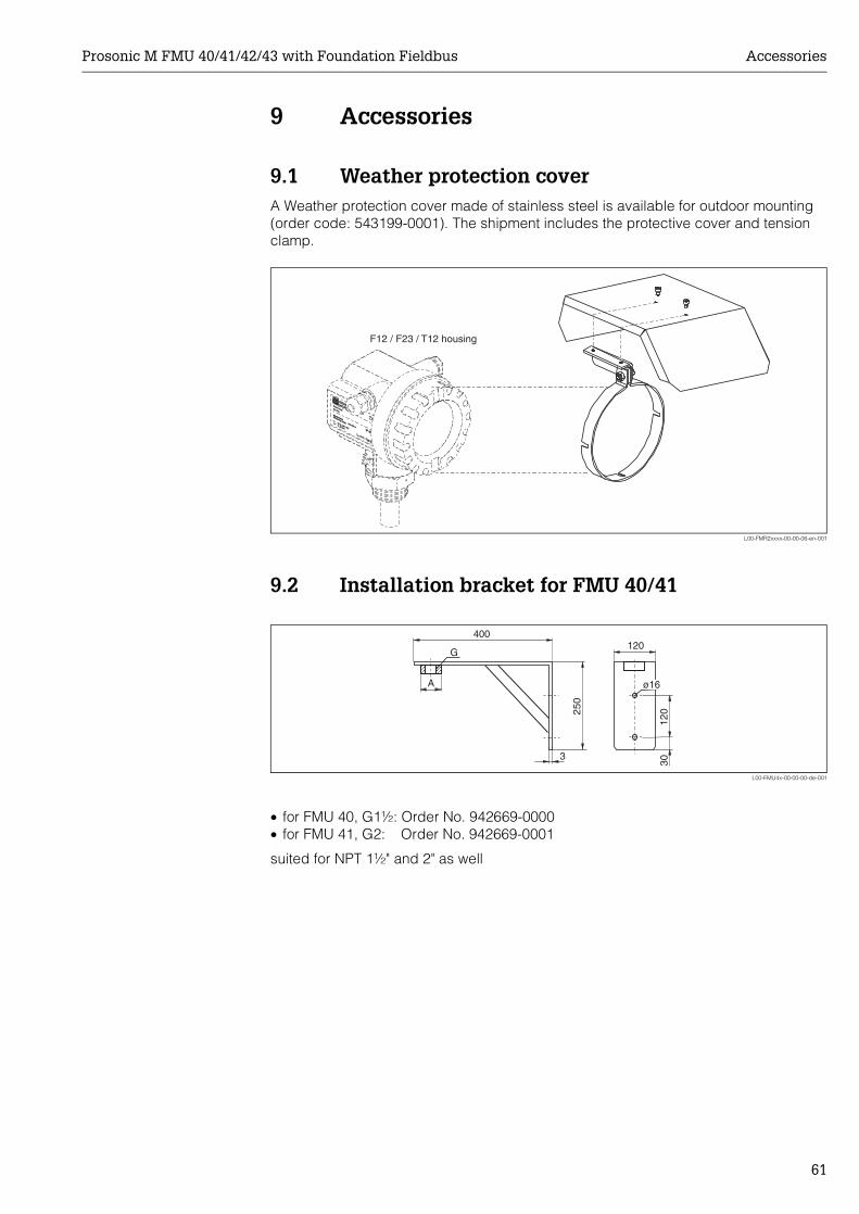
Prosonic M FMU 40/41/42/43 with Foundation Fieldbus Accessories
61
9 Accessories
9.1 Weather protection coverA Weather protection cover made of stainless steel is available for outdoor mounting (order code: 543199-0001). The shipment includes the protective cover and tension clamp.
L00-FMR2xxxx-00-00-06-en-001
9.2 Installation bracket for FMU 40/41
L00-FMU4x-00-00-00-de-001
• for FMU 40, G1½: Order No. 942669-0000• for FMU 41, G2: Order No. 942669-0001
suited for NPT 1½" and 2" as well
ENDRESS+HAUSER
MICROPILOT II
ENDRESS+HAUSER
MICROPILOT II
IP 65IP 65
Order Code:Ser.-No.:
Order Code:Ser.-No.:
MessbereichMeasuring range
MessbereichMeasuring rangeU 16...36 V DC
4...20 mA
U 16...36 V DC4...20 mA
max. 20 m
max. 20 m
Ma
de
in G
erm
any
Ma
ulb
urg
Ma
de
in G
erm
any
Ma
ulb
urg
T>70°C :
A
t >85°C
T>70°C :
A
t >85°C
F12 / F23 / T12 housing
400120
120
30
250
A
G
ø16
3
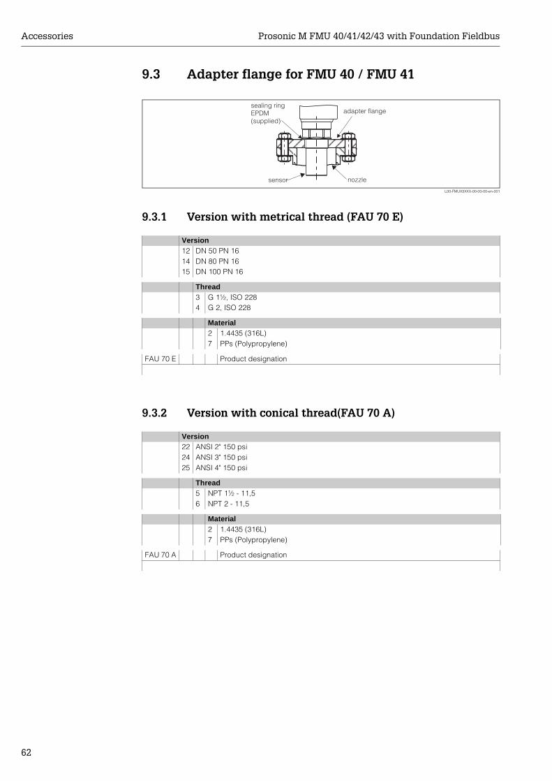
Accessories Prosonic M FMU 40/41/42/43 with Foundation Fieldbus
62
9.3 Adapter flange for FMU 40 / FMU 41
L00-FMUX3XXX-00-00-00-en-001
9.3.1 Version with metrical thread (FAU 70 E)
9.3.2 Version with conical thread(FAU 70 A)
Version12 DN 50 PN 1614 DN 80 PN 1615 DN 100 PN 16
Thread3 G 1½, ISO 2284 G 2, ISO 228
Material2 1.4435 (316L)7 PPs (Polypropylene)
FAU 70 E Product designation
Version22 ANSI 2" 150 psi24 ANSI 3" 150 psi25 ANSI 4" 150 psi
Thread5 NPT 1½ - 11,56 NPT 2 - 11,5
Material2 1.4435 (316L)7 PPs (Polypropylene)
FAU 70 A Product designation
adapter flangesealing ringEPDM(supplied)
sensor nozzle
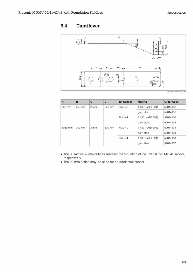
Prosonic M FMU 40/41/42/43 with Foundation Fieldbus Accessories
63
9.4 Cantilever
L00-FMU4xxxx-06-00-00-yy-005
• The 50 mm or 62 mm orifices serve for the mounting of the FMU 40 or FMU 41 sensor, respecitvely.
• The 22 mm orifice may be used for an additional sensor.
A B C D for Sensor Material Order Code
585 mm 250 mm 2 mm 200 mm FMU 40 1.4301 (AISI 304) 52014132
galv. steel 52014131
FMU 41 1.4301 (AISI 304) 52014136
galv. steel 52014135
1085 mm 750 mm 3 mm 300 mm FMU 40 1.4301 (AISI 304) 52014134
galv. steel 52014133
FMU 41 1.4301 (AISI 304) 52014138
galv. steel 52014137
A
D M8
35 50
20
2010
5
50/
62 22
C
C
6.5 15
100
25
351007575 B
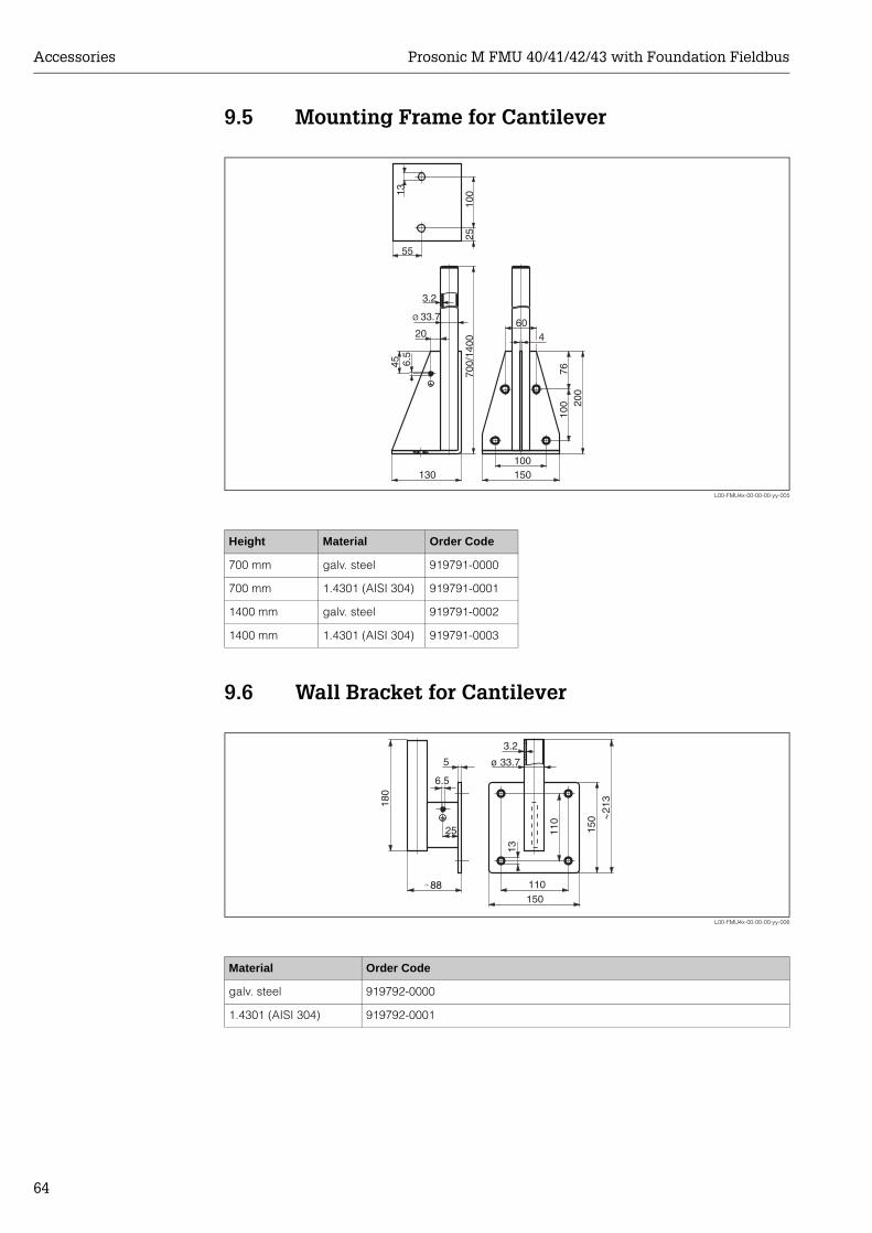
Accessories Prosonic M FMU 40/41/42/43 with Foundation Fieldbus
64
9.5 Mounting Frame for Cantilever
L00-FMU4x-00-00-00-yy-005
9.6 Wall Bracket for Cantilever
L00-FMU4x-00-00-00-yy-006
Height Material Order Code
700 mm galv. steel 919791-0000
700 mm 1.4301 (AISI 304) 919791-0001
1400 mm galv. steel 919791-0002
1400 mm 1.4301 (AISI 304) 919791-0003
Material Order Code
galv. steel 919792-0000
1.4301 (AISI 304) 919792-0001
3.2
20
55
100
2570
0/14
00
45
7610
0 200
6.5
13
Ø 33.7
130 150100
604
110
25
5
6.5
150
ø 33.7
3.2
110
13
150
180
213
88
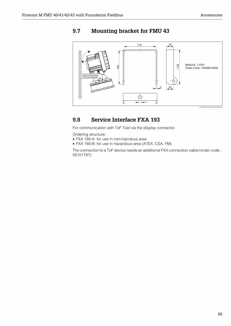
Prosonic M FMU 40/41/42/43 with Foundation Fieldbus Accessories
65
9.7 Mounting bracket for FMU 43
L00-FMU4x-00-00-00-en-003.eps
9.8 Service Interface FXA 193For communication with ToF Tool via the display connector.
Ordering structure:• FXA 193-A: for use in non-hazrdous area• FXA 193-B: for use in hazardous area (ATEX, CSA, FM)
The connection to a ToF device needs an additional FXA connection cable (order code.: 50101787).
11
119
2
25
120
~12
3
25
Material: 1.4301Order-Code.: 942666-0000
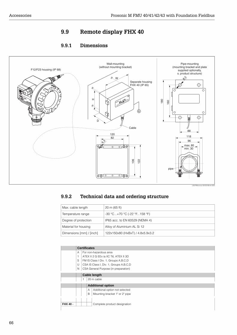
Accessories Prosonic M FMU 40/41/42/43 with Foundation Fieldbus
66
9.9 Remote display FHX 40
9.9.1 Dimensions
L00-FMxxxxxx-00-00-06-en-003
9.9.2 Technical data and ordering structure
ENDRESS+HAUSER
ENDRESS+HAUSER
IP 65
Order Code:Ser.-No.:
Order Code:Ser.-No.:
MessbereichMeasuring range
MessbereichMeasuring rangeU 16...36 V DC
4...20 mA
U 16...36 V DC4...20 mA
max. 20 m
max. 20 m
Made in
Germ
any
M
aulb
urg
T>70°C :
A
t >85°C
T>70°C :
A
t >85°C
82
6,3
106
122
120
max. 80min. 30
96
88
160
8,5
118
180
Separate housingFHX 40 (IP 65)
F12/F23 housing (IP 68)
Cable
H
W
D
Wall-mounting(without mounting bracket)
Pipe-mounting(mounting bracket and plate
supplied optionally,s. product structure)
pipe
Max. cable length 20 m (65 ft)
Temperature range -30 °C...+70 °C (-22 °F...158 °F)
Degree of protection IP65 acc. to EN 60529 (NEMA 4)
Material for housing Alloy of Aluminium AL Si 12
Dimensions [mm] / [inch] 122x150x80 (HxBxT) / 4.8x5.9x3.2
CertificatesA For non-hazardous area1 ATEX II 2 G EEx ia IIC T6, ATEX II 3DS FM IS Class I Div. 1, Groups A,B,C,DU CSA IS Class I, Div. 1, Groups A,B,C,DN CSA General Purpose (in preparation)
Cable length1 20 m cable
Additional optionA Additional option not selectedB Mounting bracket 1" or 2" pipe
FHX 40 - Complete product designation
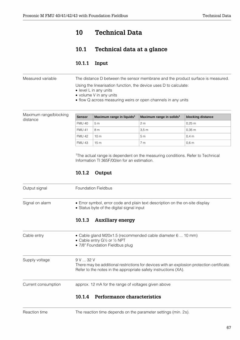
Prosonic M FMU 40/41/42/43 with Foundation Fieldbus Technical Data
67
10 Technical Data
10.1 Technical data at a glance
10.1.1 Input
Measured variable The distance D between the sensor membrane and the product surface is measured.
Using the linearisation function, the device uses D to calculate:• level L in any units• volume V in any units• flow Q across measuring weirs or open channels in any units
Maximum range/blocking distance
1The actual range is dependent on the measuring conditions. Refer to Technical Information TI 365F/00/en for an estimation.
10.1.2 Output
Output signal Foundation Fieldbus
Signal on alarm • Error symbol, error code and plain text description on the on-site display• Status byte of the digital signal input
10.1.3 Auxiliary energy
Cable entry • Cable gland M20x1.5 (recommended cable diameter 6 ... 10 mm)• Cable entry G½ or ½ NPT• 7/8" Foundation Fieldbus plug
Supply voltage 9 V ... 32 VThere may be additional restrictions for devices with an explosion protection certificate. Refer to the notes in the appropriate safety instructions (XA).
Current consumption approx. 12 mA for the range of voltages given above
10.1.4 Performance characteristics
Reaction time The reaction time depends on the parameter settings (min. 2s).
Sensor Maximum range in liquids1 Maximum range in solids1 blocking distance
FMU 40 5 m 2 m 0,25 m
FMU 41 8 m 3,5 m 0,35 m
FMU 42 10 m 5 m 0,4 m
FMU 43 15 m 7 m 0,6 m
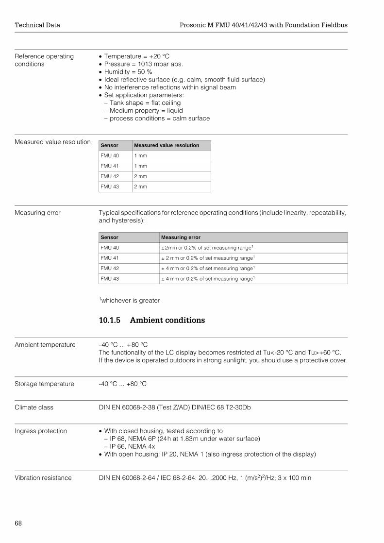
Technical Data Prosonic M FMU 40/41/42/43 with Foundation Fieldbus
68
Reference operating conditions
• Temperature = +20 °C• Pressure = 1013 mbar abs.• Humidity = 50 %• Ideal reflective surface (e.g. calm, smooth fluid surface)• No interference reflections within signal beam• Set application parameters:
– Tank shape = flat ceiling– Medium property = liquid– process conditions = calm surface
Measured value resolution
Measuring error Typical specifications for reference operating conditions (include linearity, repeatability, and hysteresis):
1whichever is greater
10.1.5 Ambient conditions
Ambient temperature -40 °C ... +80 °CThe functionality of the LC display becomes restricted at Tu<-20 °C and Tu>+60 °C.If the device is operated outdoors in strong sunlight, you should use a protective cover.
Storage temperature -40 °C ... +80 °C
Climate class DIN EN 60068-2-38 (Test Z/AD) DIN/IEC 68 T2-30Db
Ingress protection • With closed housing, tested according to– IP 68, NEMA 6P (24h at 1.83m under water surface)– IP 66, NEMA 4x
• With open housing: IP 20, NEMA 1 (also ingress protection of the display)
Vibration resistance DIN EN 60068-2-64 / IEC 68-2-64: 20…2000 Hz, 1 (m/s2)2/Hz; 3 x 100 min
Sensor Measured value resolution
FMU 40 1 mm
FMU 41 1 mm
FMU 42 2 mm
FMU 43 2 mm
Sensor Measuring error
FMU 40 ±2mm or 0.2% of set measuring range1
FMU 41 ± 2 mm or 0,2% of set measuring range1
FMU 42 ± 4 mm or 0,2% of set measuring range1
FMU 43 ± 4 mm or 0,2% of set measuring range1
Prosonic M FMU 40/41/42/43 with Foundation Fieldbus Technical Data
69
Electromagnetic compatibility (EMC)
• Interference emission to EN 61326, Equipment Class B• Interference immunity to EN 61326, Appendix A (Industrial) and NAMUR
Recommendation NE 21 (EMC).• A standard installation cable is sufficient if only the analogue signal is used. Use a
screened cable when working with a superimposed communication signal (HART).
10.1.6 Process conditions
Process temperature -40°C ... +80°CA temperature sensor is integrated in the sensor for temperature-dependent time-of-flight correction.
Process pressure • FMU 40/41: 3bar abs.• FMU 42/43: 2,5bar abs.
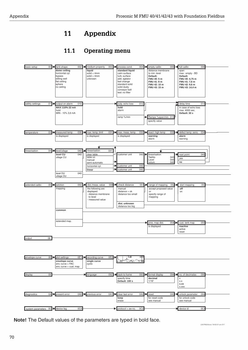
Appendix Prosonic M FMU 40/41/42/43 with Foundation Fieldbus
70
11 Appendix
11.1 Operating menu
L00-FMU4xxxx-19-00-01-en-017
safety settings
basic setup
output on alarm
MAX 110% 22 mAholdMIN - 10% 3,6 mA
tank shape
dome ceilinghorizontal cyl.bypassstilling wellflat ceilingsphereno ceiling
measured temp.
is displayed
level/ullage
level DUullage DU
level CUullage CU
selction
mapping
common
extended map.
plot settings
envelope curveenv. curve + FACenv. curve + cust. map
present error
device tag
specify value
medium property
solid < 4mmsolid > 4mmunknown
liquid
max. temp. limit
is displayed
linearisation
table onmanualsemi-automatic
horizontal cyl.
linear
recording curve
single curvecyclic
language
previous error
outp. echo loss
holdalarm
ramp %/min
process cond.
standard liquidcalm surfaceturb. surfaceadd. agitatorfast changestandard solidsolid dustyconveyor belttest: no filter
max. meas. temp.
is displayed
customer unitTabNoLevelvolum
customer unit
customer unit
back to home
specify timeDefault: 100 s
clear last error
keeperase
protocol + sw-no.
Rampe %span/min
empty calibr.
distance membraneto min. levelDefault:FMU 40: 5 mFMU 41: 8 mFMU 42: 10 mFMU 43: 15 m
react. high temp
warningalarm
linearisation
pres. map dist.
is displayed
format display
decimal1/16”
reset
for reset codesee manual
Note! The Default values of the parameters are typed in bold face.
delay time
in case of echo lossmax. 4000 sec.Default: 30 s
full calibr.
spanmax.: empty - BDDefault:FMU 40: 4,75 mFMU 41: 7,6 mFMU 42: 9,6 mFMU 43: 14,4 m
defect temp. sens.
alarmwarning
next point
yes
no
cust. tank map
inactiveactivereset
no. of decimalas
xx.x
x.xxxx.xx
unlock parameter
for unlock codesee manual
device id
temperature
linearisation
extended calibr.
envelope curve
display
diagnostics
system parameters
01
00
010
002
030
040
040
040
050
0E1
0A0
0C0
003
031
041
0E2
092
0A1
012
004
032
042043044045
042
042
093
0A2
0C2
013
005
033
054
094
0A3
014
006
034
045
055
095
0A4
0C4
03
04
05
0E
09
0A
0C
clear table
dist./meas. value
the following aredisplayed:- distance membrane
to level- measured value
check distance
manualdistance = okdistance too small
distance too bigdist. unknown
range of mapping.
accept proposed valueorspecify range ofmapping
start mapping
offon
008 051 052 053
output 06
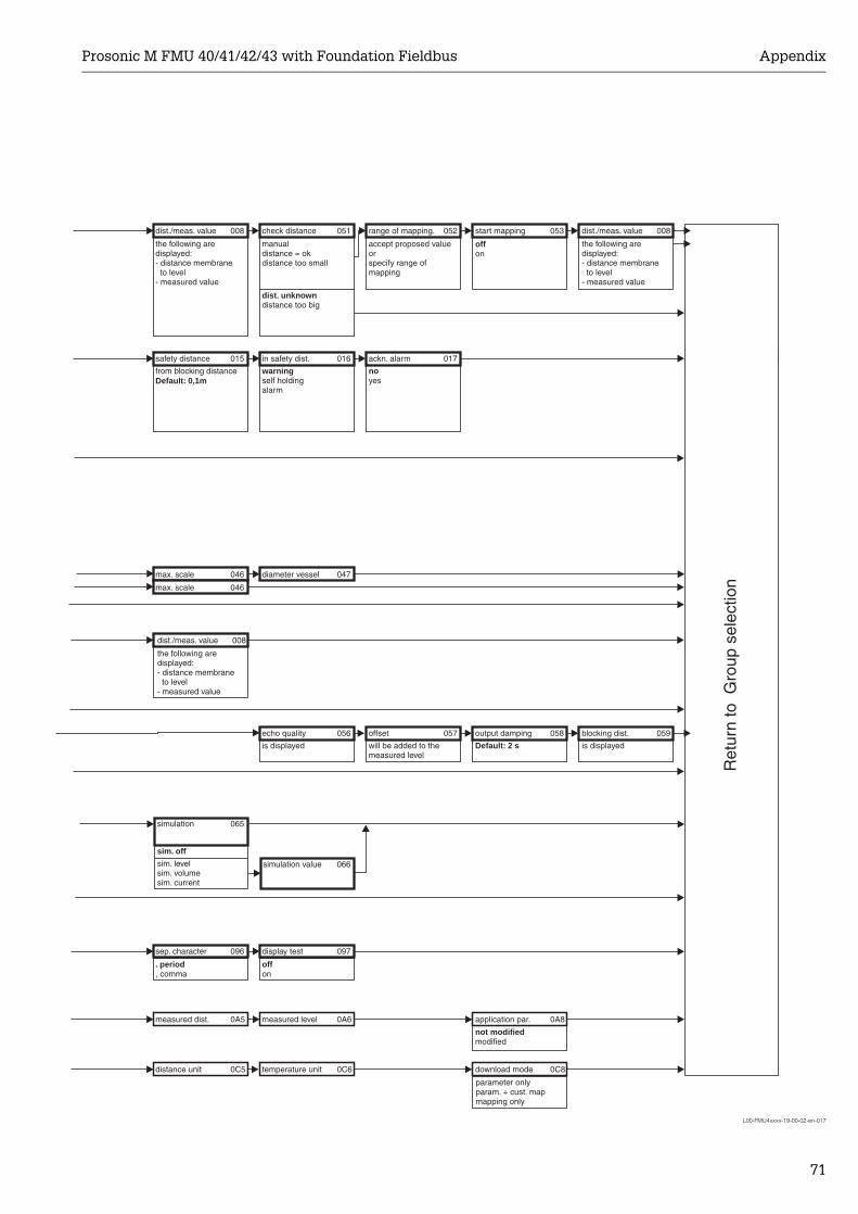
Prosonic M FMU 40/41/42/43 with Foundation Fieldbus Appendix
71
L00-FMU4xxxx-19-00-02-en-017
sep. character
. period, comma
measured dist.
distance unit
max. scale
max. scale
safety distance
from blocking distanceDefault: 0,1m
dist./meas. value
the following aredisplayed:- distance membraneto level
- measured value
echo quality
is displayed
display test
offon
measured level
temperature unit
diameter vessel
in safety dist.
warningself holdingalarm
check distance
manualdistance = okdistance too small
distance too bigdist. unknown
offset
will be added to themeasured level
ackn. alarm
noyes
range of mapping.
accept proposed valueorspecify range ofmapping
output damping
Default: 2 s
application par.
Ret
urn
to G
roup
sel
ectio
n
not modifiedmodified
download mode
parameter onlyparam. + cust. mapmapping only
start mapping
offon
blocking dist.
is displayed
dist./meas. value
the following aredisplayed:- distance membraneto level
- measured value
096
0A5
0C5
046
046
015
008
056
097
0A6
0C6
047
016
051
057
017
052
058
0A8
0C8
053
059
008
dist./meas. value
the following aredisplayed:- distance membraneto level
- measured value
008
simulation
sim. off
sim. levelsim. volumesim. current
simulation value
065
066
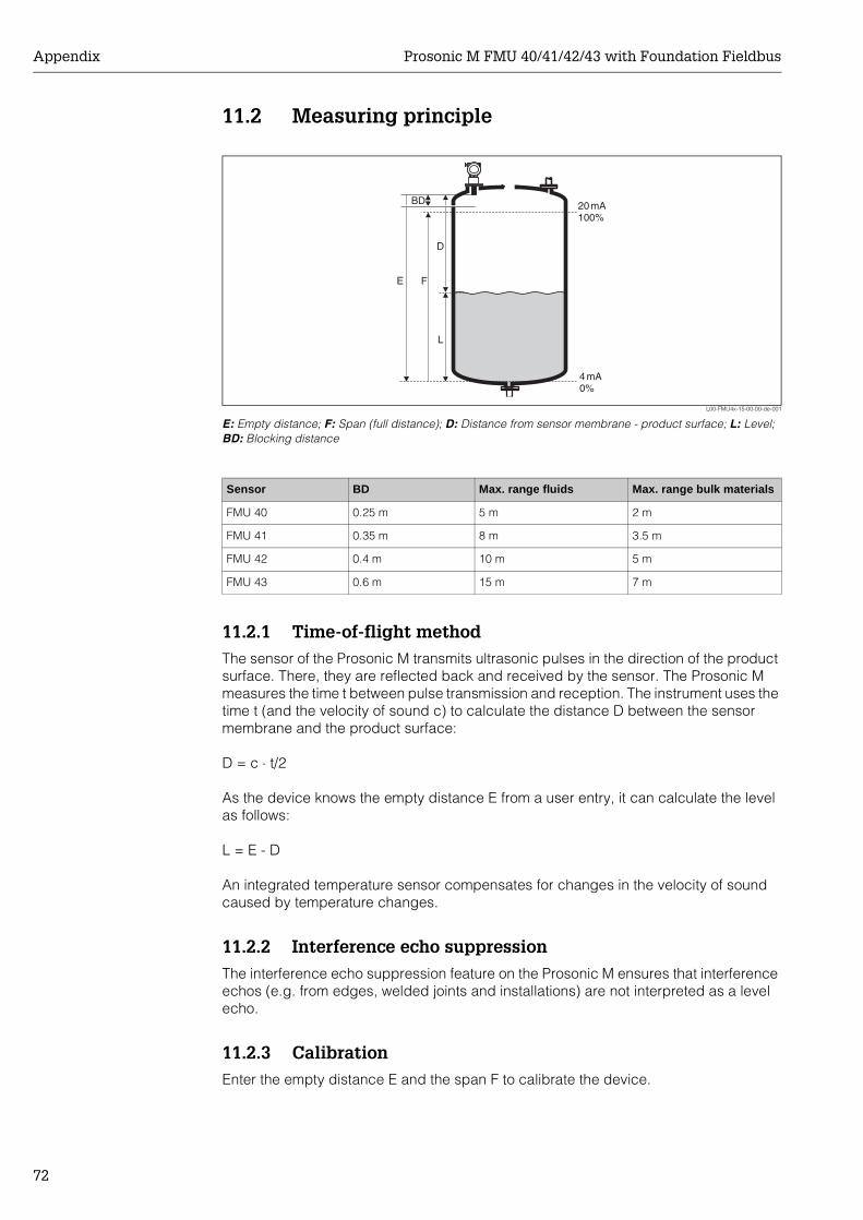
Appendix Prosonic M FMU 40/41/42/43 with Foundation Fieldbus
72
11.2 Measuring principle
L00-FMU4x-15-00-00-de-001
E: Empty distance; F: Span (full distance); D: Distance from sensor membrane - product surface; L: Level; BD: Blocking distance
11.2.1 Time-of-flight methodThe sensor of the Prosonic M transmits ultrasonic pulses in the direction of the product surface. There, they are reflected back and received by the sensor. The Prosonic M measures the time t between pulse transmission and reception. The instrument uses the time t (and the velocity of sound c) to calculate the distance D between the sensor membrane and the product surface:
D = c ⋅ t/2
As the device knows the empty distance E from a user entry, it can calculate the level as follows:
L = E - D
An integrated temperature sensor compensates for changes in the velocity of sound caused by temperature changes.
11.2.2 Interference echo suppressionThe interference echo suppression feature on the Prosonic M ensures that interference echos (e.g. from edges, welded joints and installations) are not interpreted as a level echo.
11.2.3 CalibrationEnter the empty distance E and the span F to calibrate the device.
20mA100%
4mA0%
D
L
FE
BD
Sensor BD Max. range fluids Max. range bulk materials
FMU 40 0.25 m 5 m 2 m
FMU 41 0.35 m 8 m 3.5 m
FMU 42 0.4 m 10 m 5 m
FMU 43 0.6 m 15 m 7 m

Prosonic M FMU 40/41/42/43 with Foundation Fieldbus Appendix
73
11.2.4 Blocking distanceSpan F may not extend into the blocking distance BD. Level echos from the blocking distance cannot be evaluated due to the transient characteristics of the sensor.
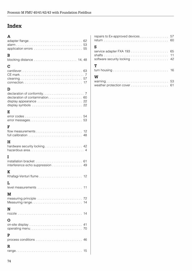
Prosonic M FMU 40/41/42/43 with Foundation Fieldbus
74
Index
Aadapter flange. . . . . . . . . . . . . . . . . . . . . . . . . . . . . . 62alarm . . . . . . . . . . . . . . . . . . . . . . . . . . . . . . . . . . . . . 53application errors . . . . . . . . . . . . . . . . . . . . . . . . . . . 55
Bblocking distance . . . . . . . . . . . . . . . . . . . . . . . . 14, 48
Ccantilever. . . . . . . . . . . . . . . . . . . . . . . . . . . . . . . . . . 63CE mark. . . . . . . . . . . . . . . . . . . . . . . . . . . . . . . . . . . . 7cleaning. . . . . . . . . . . . . . . . . . . . . . . . . . . . . . . . . . . 57connection. . . . . . . . . . . . . . . . . . . . . . . . . . . . . . . . . 17
Ddeclaration of conformity. . . . . . . . . . . . . . . . . . . . . . . 7declaration of contamination. . . . . . . . . . . . . . . . . . . 60display appearance . . . . . . . . . . . . . . . . . . . . . . . . . 22display symbols . . . . . . . . . . . . . . . . . . . . . . . . . . . . 22
Eerror codes . . . . . . . . . . . . . . . . . . . . . . . . . . . . . . . . 54error messages . . . . . . . . . . . . . . . . . . . . . . . . . . . . . 53
Fflow measurements . . . . . . . . . . . . . . . . . . . . . . . . . . 12full calibration . . . . . . . . . . . . . . . . . . . . . . . . . . . . . . 48
Hhardware security locking . . . . . . . . . . . . . . . . . . . . . 42hazardous area . . . . . . . . . . . . . . . . . . . . . . . . . . . . . . 4
Iinstallation bracket . . . . . . . . . . . . . . . . . . . . . . . . . . 61interference echo suppression . . . . . . . . . . . . . . . . . 49
KKhafagi-Venturi flume . . . . . . . . . . . . . . . . . . . . . . . . 12
Llevel measurements . . . . . . . . . . . . . . . . . . . . . . . . . 11
Mmeasuring principle . . . . . . . . . . . . . . . . . . . . . . . . . 72Measuring range. . . . . . . . . . . . . . . . . . . . . . . . . . . . 14
Nnozzle . . . . . . . . . . . . . . . . . . . . . . . . . . . . . . . . . . . . 14
Oon-site display . . . . . . . . . . . . . . . . . . . . . . . . . . . . . . 41operating menu . . . . . . . . . . . . . . . . . . . . . . . . . . . . . 70
Pprocess conditions . . . . . . . . . . . . . . . . . . . . . . . . . . 46
Rrange. . . . . . . . . . . . . . . . . . . . . . . . . . . . . . . . . . . . . 15
repairs to Ex-approved devices. . . . . . . . . . . . . . . . 57return . . . . . . . . . . . . . . . . . . . . . . . . . . . . . . . . . . . . 60
Sservice adapter FXA 193 . . . . . . . . . . . . . . . . . . . . . 65shafts . . . . . . . . . . . . . . . . . . . . . . . . . . . . . . . . . . . . 11software security locking . . . . . . . . . . . . . . . . . . . . . 42
Tturn housing . . . . . . . . . . . . . . . . . . . . . . . . . . . . . . . 16
Wwarning. . . . . . . . . . . . . . . . . . . . . . . . . . . . . . . . . . . 53weather protection cover . . . . . . . . . . . . . . . . . . . . . 61
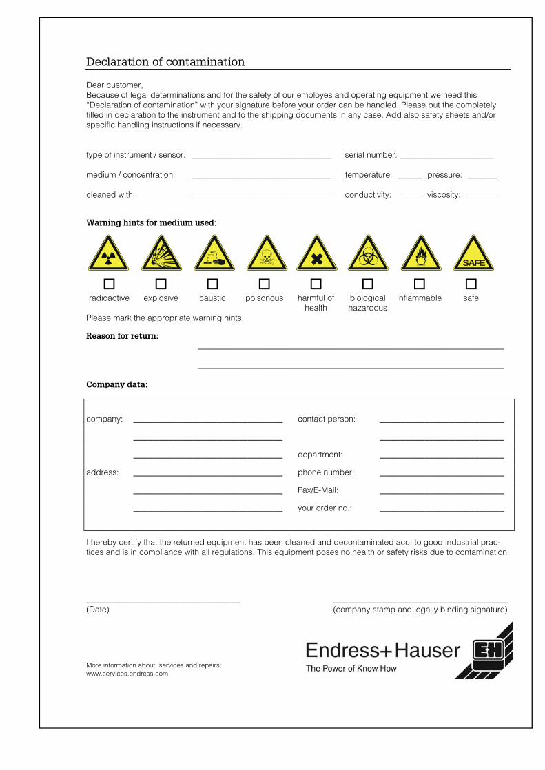
More information about services and repairs:www.services.endress.com
Declaration of contamination
Dear customer,Because of legal determinations and for the safety of our employes and operating equipment we need this“Declaration of contamination” with your signature before your order can be handled. Please put the completelyfilled in declaration to the instrument and to the shipping documents in any case. Add also safety sheets and/orspecific handling instructions if necessary.
type of instrument / sensor: __________________________________ serial number: _______________________
medium / concentration: __________________________________ temperature: ______ pressure: _______
cleaned with: __________________________________ conductivity: ______ viscosity: _______
���������������� ���� �����
�radioactive
�explosive
�caustic
�poisonous
�harmful of
health
�biologicalhazardous
�inflammable
�safe
Please mark the appropriate warning hints.
�������������������������������������������������������������������������������������������
���������������������������������������������������������������������������
�� ���������
company: ______________________________ contact person: _________________________
______________________________ _________________________
______________________________ department: _________________________
address: ______________________________ phone number: _________________________
______________________________ Fax/E-Mail: _________________________
______________________________ your order no.: _________________________
I hereby certify that the returned equipment has been cleaned and decontaminated acc. to good industrial prac-tices and is in compliance with all regulations. This equipment poses no health or safety risks due to contamination.
_______________________________ ___________________________________(Date) (company stamp and legally binding signature)
SAFE
Europe
Austria – Wien❑ Endress+Hauser Ges.m.b.H.Tel. (01) 88 05 60, Fax (01) 88 05 63 35
Belarus – MinskBelorgsintezTel. (017) 2 50 84 73, Fax (017) 2 50 85 83
Belgium / Luxembourg – Bruxelles❑ Endress+Hauser S.A. / N.V.Tel. (02) 2 48 06 00, Fax (02) 2 48 05 53
Bulgaria – SofiaIntertech-Automation Ltd.Tel. (02) 9 62 71 52, Fax (02) 9 62 14 71
Croatia – Zagreb❑ Endress+Hauser GmbH+Co.Tel. (01) 6 63 77 85, Fax (01) 6 63 78 23
Cyprus – NicosiaI+G Electrical Services Co. Ltd.Tel. (02) 48 47 88, Fax (02) 48 46 90
Czech Republic – Praha❑ Endress+Hauser Czech s.r.o.Tel. (02) 66 78 42 00, Fax (026) 66 78 41 79
Denmark – Søborg❑ Endress+Hauser A/STel. (70) 13 11 32, Fax (70) 13 21 33
Estonia – TartuElvi-Aqua OÜTel. (7) 30 27 32, Fax (7) 30 27 31
Finland – Helsinki❑ Metso Endress+Hauser OyTel. (204) 8 31 60, Fax (204) 8 31 61
France – Huningue❑ Endress+Hauser S.A.Tel. (389) 69 67 68, Fax (389) 69 48 02
Germany – Weil am Rhein❑ Endress+Hauser Messtechnik GmbH+Co. KGTel. (07621) 9 75 01, Fax (07621) 97 55 55
Great Britain – Manchester❑ Endress+Hauser Ltd.Tel. (0161) 2 86 50 00, Fax (0161) 9 98 18 41
Greece – AthensI & G Building Services Automation S.A.Tel. (01) 9 24 15 00, Fax (01) 9 22 17 14
Hungary – Budapest❑ Endress+Hauser MagyarországTel. (01) 4 12 04 21, Fax (01) 4 12 04 24
Iceland – ReykjavikSindra-Stál hfTel. 5 75 00 00, Fax 5 75 00 10
Ireland – Clane / County Kildare❑ Flomeaco Endress+Hauser Ltd.Tel. (045) 86 86 15, Fax (045) 86 81 82
Italy – Cernusco s/N, Milano❑ Endress+Hauser S.p.A.Tel. (02) 92 19 21, Fax (02) 92 19 23 62
Latvia – RigaElekoms Ltd.Tel. (07) 33 64 44, Fax (07) 33 64 48
Lithuania – KaunasUAB Agava Ltd.Tel. (03) 7 20 24 10, Fax (03) 7 20 74 14
Macedonia – BeogradMeris d.o.o.Tel. (11) 44 42 96 6, Fax (11) 30 85 77 8
Moldavia – ChisinauS.C. Techno Test SRLTel. (02) 22 61 60, Fax (02) 22 83 13
Netherlands – Naarden❑ Endress+Hauser B.V.Tel. (035) 6 95 86 11, Fax (035) 6 95 88 25
Norway – Lierskogen❑ Endress+Hauser A/STel. 32 85 98 50, Fax 32 85 98 51
Poland – Wroclaw❑ Endress+Hauser Polska Sp. z o.o.Tel. (071) 7 80 37 00, Fax (071) 7 80 37 60
Portugal – Cacem❑ Endress+Hauser Lda.Tel. (21) 4 26 72 90, Fax (21) 4 26 72 99
Romania – BucharestRomconseng S.R.L.Tel. (021) 41 12 50 1, Fax (021) 41 01 63 4
Russia – Moscow❑ Endress+Hauser GmbH+CoTel. (095) 78 32 85 0, Fax (095) 78 32 85 5
Slovak Republic – BratislavaTranscom Technik s.r.o.Tel. (2) 44 88 86 90, Fax (2) 44 88 71 12
Slovenia – Ljubljana❑ Endress+Hauser (Slovenija) D.O.O.Tel. (01) 5 19 22 17, Fax (01) 5 19 22 98
Spain – Sant Just Desvern❑ Endress+Hauser S.A.Tel. (93) 4 80 33 66, Fax (93) 4 73 38 39
Sweden – Sollentuna❑ Endress+Hauser ABTel. (08) 55 51 16 00, Fax (08) 55 51 16 55
Switzerland – Reinach/BL 1❑ Endress+Hauser Metso AGTel. (061) 7 15 75 75, Fax (061) 7 11 16 50
Turkey – Levent/IstanbulIntek Endüstriyel Ölcü ve Kontrol SistemleriTel. (0212) 2 75 13 55, Fax (0212) 2 66 27 75
Ukraine – KievPhotonika GmbHTel. (44) 2 68 81 02, Fax (44) 2 69 07 05
Yugoslavia Republic – BeogradMeris d.o.o.Tel. (11) 4 44 29 66, Fax (11) 3 08 57 78
Africa
Algeria – AnnabaSymes Systemes et MesuresTel. (38) 88 30 03, Fax (38) 88 30 02
Egypt – Heliopolis/CairoAnasia Egypt For Trading (S.A.E.)Tel. (02) 2 68 41 59, Fax (02) 2 68 41 69
Morocco – CasablancaOussama S.A.Tel. (02) 22 24 13 38, Fax (02) 2 40 26 57
Rep. South Africa – Sandton❑ Endress+Hauser (Pty.) Ltd.Tel. (011) 2 62 80 00, Fax (011) 2 62 80 62
Tunisia – TunisCMR Controle, Maintenance et RegulationTel. (07) 17 93 07 7, Fax (07) 17 88 59 5
America
Argentina – Buenos Aires❑ Endress+Hauser Argentina S.A.Tel. (11) 45 22 79 70, Fax (11) 45 22 79 09
Brazil – Sao Paulo❑ Samson Endress+Hauser Ltda.Tel. (011) 50 33 43 33, Fax (011) 50 31 30 67
Canada – Burlington, Ontario❑ Endress+Hauser Canada Ltd.Tel. (905) 68 19 29 2, Fax (905) 68 19 44 4
Chile – Santiago de Chile❑ Endress+Hauser (Chile) Ltd.Tel. (02) 3 21 30 09, Fax (02) 3 21 30 25
Colombia – Bogota D.C.Colsein Ltda.Tel. (01) 2 36 76 59, Fax (01) 6 10 78 68
Costa Rica – San JoseEuro-Tec S.A.Tel. 2 20 28 08, Fax 2 96 15 42
Ecuador – QuitoInsetec Cia. Ltda.Tel. (02) 2 26 91 48, Fax (02) 2 46 18 33
El Salvador – San SalvadorAutomatizacion y Control Industrial de El Salvador, S.A. de C.V.Tel. 2 60 24 24, Fax 2 60 56 77
Guatemala – Ciudad de GuatemalaAutomatizacion y Control Industrial, S.A.Tel. (03) 34 59 85, Fax (03) 32 74 31
Honduras – San Pedro Sula, CortesAutomatizacion y Control Industrial de Honduras, S.A. de C.V.Tel. 5 57 91 36, Fax 5 57 91 39
Mexico – México, D.F❑ Endress+Hauser (México), S.A. de C.V.Tel. (5) 5 55 68 24 07, Fax (5) 5 55 68 74 59
Nicaragua – ManaguaAutomatización y Control Industrial de Nicaragua, S.A.Tel. 2 22 61 90, Fax 2 28 70 24
Peru – MirafloresCorsusa InternationalTel. (1) 44 41 20 0, Fax (1) 44 43 66 4
USA – Greenwood, Indiana❑ Endress+Hauser Inc.Tel. (317) 5 35 71 38, Fax (317) 5 35 84 98
USA – Norcross, Atlanta❑ Endress+Hauser Systems & Gauging Inc.Tel. (770) 4 47 92 02, Fax (770) 4 47 57 67
Venezuela – CaracasControval C.A.Tel. (212) 9 44 09 66, Fax (212) 9 44 45 54
Asia
Azerbaijan – BakuModcon Systems - BakuTel. (12) 92 98 59, Fax (12) 99 13 72
Brunei – Negara Brunei DarussalamAmerican International Industries (B) Sdn. Bhd.Tel. (3) 22 37 37, Fax (3) 22 54 58
Cambodia – Khan Daun Penh, Phom PenhComin Khmere Co. Ltd.Tel. (23) 42 60 56, Fax (23) 42 66 22
China – Shanghai❑ Endress+Hauser (Shanghai) Instrumentation Co. Ltd.Tel. (021) 54 90 23 00, Fax (021) 54 90 23 03
China – Beijing❑ Endress+Hauser (Beijing) Instrumentation Co. Ltd.Tel. (010) 65 88 24 68, Fax (010) 65 88 17 25
Hong Kong – Tsimshatsui / Kowloon❑ Endress+Hauser (H.K.) Ltd.Tel. 8 52 25 28 31 20, Fax 8 52 28 65 41 71
India – Mumbai❑ Endress+Hauser (India) Pvt. Ltd.Tel. (022) 56 93 83 33, Fax (022) 56 93 88 330
Indonesia – JakartaPT Grama BazitaTel. (21) 7 95 50 83, Fax (21) 7 97 50 89
Iran – TehranPatsa IndustryTel. (021) 8 72 68 69, Fax (021) 8 71 96 66
Israel – NetanyaInstrumetrics Industrial Control Ltd.Tel. (09) 8 35 70 90, Fax (09) 8 35 06 19
Japan – Tokyo❑ Sakura Endress Co. Ltd.Tel. (0422) 54 06 11, Fax (0422) 55 02 75
Jordan – AmmanA.P. Parpas Engineering S.A.Tel. (06) 5 53 92 83, Fax (06) 5 53 92 05
Kazakhstan – AlmatyBEI ElectroTel. (72) 30 00 28, Fax (72) 50 71 30
Korea, South – Seoul❑ Endress+Hauser (Korea) Co. Ltd.Tel. (02) 26 58 72 00, Fax (02) 26 59 28 38
Kuwait – SafatUnited Technical Services Est. For General TradingTel. 2 41 12 63, Fax 2 41 15 93
Lebanon – Jbeil Main EntryNetwork EngineeringTel. (3) 94 40 80, Fax (9) 54 80 38
Malaysia – Shah Alam, Selangor Darul Ehsan❑ Endress+Hauser (M) Sdn. Bhd.Tel. (03) 78 46 48 48, Fax (03) 78 46 88 00
Pakistan – KarachiSpeedy AutomationTel. (021) 7 72 29 53, Fax (021) 7 73 68 84
Philippines – Pasig City, Metro Manila❑ Endress+Hauser (Phillipines) Inc.Tel. (2) 6 38 18 71, Fax (2) 6 38 80 42
Saudi Arabia – JeddahAnasia Trading Est.Tel. (02) 6 53 36 61, Fax (02) 6 53 35 04
Singapore – Singapore❑ Endress+Hauser (S.E.A.) Pte. Ltd.Tel. (65) 66 82 22, Fax (65) 66 68 48
Sultanate of Oman – RuwiMustafa & Sultan Sience & Industry Co. L.L.C.Tel. 63 60 00, Fax 60 70 66
Taiwan – TaipeiKingjarl CorporationTel. (02) 27 18 39 38, Fax (02) 27 13 41 90
Thailand – Bangkok 10210❑ Endress+Hauser (Thailand) Ltd.Tel. (2) 9 96 78 11-20, Fax (2) 9 96 78 10
United Arab Emirates – DubaiDescon Trading L.L.C.Tel. (04) 2 65 36 51, Fax (04) 2 65 32 64
Uzbekistan – TashkentIm Mexatronika-TesTel. (71) 1 91 77 07, Fax (71) 1 91 76 94
Vietnam – Ho Chi Minh CityTan Viet Bao Co. Ltd.Tel. (08) 8 33 52 25, Fax (08) 8 33 52 27
Australia + New Zealand
Australia – North Ryde NSW 2113❑ Endress+Hauser Australia Pty. Ltd.Tel. (02) 88 77 70 00, Fax (02) 88 77 70 99
New Zealand – AucklandEMC Industrial Group Ltd.Tel. (09) 4 15 51 10, Fax (09) 4 15 51 15
All other countries❑ Endress+Hauser GmbH+Co. KGInstruments InternationalWeil am Rhein, GermanyTel. (07621) 9 75 02, Fax (07621) 97 53 45
❑ Members of the Endress+Hauser group
http://www.endress.com
05.03
BA 239F/00/en/02.04CCS/FM+SGML 6.0/ProMoDo