Embed Size (px)
Citation preview

OW
NER
’S M
AN
UA
L M
AN
UA
LE D
’USO
MA
NU
EL D
’UTI
LISA
TIO
NM
AN
UA
L D
E IN
STR
UC
CIO
NES
2003
BED
IEN
UN
GSA
NLE
ITU
NG
Art
.Nr.
3.2
10
.57
9
/20
02
64
0LC
4 A
DV
ENTU
RE

EN
GLIS
H
1
IMPORTANT
WE STRONGLY SUGGEST THAT YOU READ THIS MANUAL
CAREFULLY AND COMPLETELY BEFORE GOING ON YOUR FIRST
RIDE. IT CONTAINS A GREAT DEAL OF INFORMATION AND
ADVICE WHICH WILL HELP YOU USE AND HANDLE YOUR BIKE
PROPERLY. IN YOUR OWN INTEREST, PLEASE PAY PARTICULAR
ATTENTION TO NOTICES THAT ARE MARKED AS FOLLOWS:
� WARNING �IGNORING THESE INSTRUCTIONS, CAN ENDANGER YOURBODY AND YOUR LIFE.
! CAUTION !IGNORING THESE INSTRUCTIONS COULD CAUSE DAMAGE TOPARTS OF YOUR MOTORCYCLE OR THAT THE MOTOR-CYCLEIS NOT ROAD-SAFE ANYMORE.
Please insert the serial numbers of your motorcycle in the boxes below
Frame number
Engine number
Key number
Stamp of dealer
Tampering with noise control system prohibitedOwners are warned that the law may prohibit:(a) The removal or rendering inoperative by any person other than for purposes of mainten-
ance, repair or replacement, of any device or element of design incorporated into any newvehicle for the purpose of noise control prior to its sale or delivery to the ultimate purchaseror while it is in use; and
(b) the use of the vehicle after such device or element of design has been removed or renderedinoperative by any person.
COMSUMER INFORMATION FOR AUSTRALIA ONLY
KTM SPORTMOTORCYCLE AG RESERVES THE RIGHT TO MODIFY ANY EQUIPMENT, TECHNICAL SPECIFICATIONS, COLORS,MATERIALS, SERVICES OFFERED AND RENDERED, AND THE LIKE SO AS TO ADAPT THEM TO LOCAL CONDITIONS WITHOUT
PREVIOUS ANNOUNCEMENT AND WITHOUT GIVING REASONS, OR TO CANCEL ANY OF THE ABOVE ITEMS WITHOUT SUBSTI-TUTING THEM WITH OTHERS. IT SHALL BE ACCEPTABLE TO STOP MANUFACTURING A CERTAIN MODEL WITHOUT PREVIOUS
ANNOUNCEMENT. IN THE EVENT OF SUCH MODIFICATIONS, PLEASE ASK YOUR LOCAL KTM DEALER FOR INFORMATION.

EN
GLIS
H
2
Introduction
We would like to congratulate you on your purchase of a KTM motorcycle.
You are now the owner of a state-of-the-art sport motorcycle that guarantees to bringyou lots of fun and enjoyment, provided that you clean and maintain it appropriately.Before you go for your first ride, be sure to read this manual carefully and thoroughly inorder to familiarize yourself with how to operate your new motorcycle and with itscharacteristics, even if this means that you will have to dedicate some of your valuabletime to this task. Only by doing so will you learn how to tune your motorcycle to yourspecific needs and how to protect yourself against injury. Besides, this manual containsimportant information on motorcycle maintenance. At the time this manual was typeset,it was up-to-date with the latest state of this production series. It cannot be completelyruled out, however, that minor discrepancies may exist resulting from further designupgrades of these motorcycles.This manual is an important part of your motorcycle andshould be passed on to any subsequent owner in case you decide to sell it.
We expressly point out that work marked with an asterisk in the chapter "Maintenancework on the chassis and engine" must be performed. If maintenance work shouldbecome necessary during a competition it should be performed by a trained mechanic.KTM strongly recommends that all service work to your KTM should be performed by aqualified KTM dealer.
For your own safety, use KTM-approved parts and accessories only. KTM is not liablefor damage that arises in connection with the use of other products.
Take special care to follow the recommended run in, inspection, and maintenanceintervals. Heeding these guidelines will significantly increase the life of your motorcycle.To ensure that all work to your KTM is performed properly and to avoid warrantyconflicts, KTM recommends that you always have your KTM serviced by a recognizedand qualified KTM dealer.
Off-road motorcycle driving is a wonderful sport and we hope that you will be able toenjoy it to the full. It may, however, involve potential problems for the environment orlead to conflicts with others. These problems or conflicts can be avoided if the motorcycleis used responsibly. To safeguard the future of motorcycle sports, make sure that you usethe motorcycle in accordance with the law, show that you are environmentally consciousand respect the rights of others.
We wish you a lot of fun when driving !
KTM SPORTMOTORCYCLE AG5230 MATTIGHOFEN, AUSTRIA
ALL RIGHTS RESERVED TO MAKE ALTERATIONS TO DESIGN AND MODEL.
© by KTM SPORTMOTORCYCLE AG, AUSTRIA All rights reserved

EN
GLIS
H
3
In accordance with the international quality managementISO 9001 standard, KTM uses quality assurance processesthat lead to the highest possible product quality.
IMPORTANT LIMITED WARRANTY ANDLIMITED GUARANTEE INFORMATION
The 640 LC4 models are designed to withstand normal use on roads andeasy terrain (unpaved roads).
The service, care and operating instructions for the engine and chassisspecified in the owner's manual must be observed to ensure that the bikeruns smoothly and to avoid premature wear.
The service work specified in the "Lubrication and Maintenance Schedule"must be performed and service records must be kept for warrantydocumentation. Lack of proper service and maintenance records ordocumentation could void warranty.
The fuels and lubricants specified in the owner's manual or those of an equalquality must be used in accordance with the maintenance schedule.
The warranty or guarantee shall become void for damage and consequentialdamage caused by manipulations or conversions to the motorcycle.
The use of the motorcycle under extreme conditions, e.g. on extremelymuddy and wet terrain, can lead to higher than average wear oncomponents such as the drive train or the brakes. In this case it may becomenecessary to service or replace wear parts before the service limit specified inthe maintenance schedule has been reached.

EN
GLIS
H
4
Index
PageSERIAL NUMBER LOCATIONS .............................................5
Chassis number............................................................5Engine number, engine type ........................................5
OPERATION INSTRUMENTS ...............................................5Clutch lever .................................................................5Hand decompression lever ...........................................5Hand brake lever .........................................................6Choke lever .................................................................6Ignition lock with 3 switch positions.............................6Multi-functional digital speedometer ..........................7Setting options in the display .......................................8Indicator lamps ............................................................9Tachometer .................................................................9Combination switch ...................................................10Starter tip switch, emergency OFF switch, light switch10Filler cap ....................................................................10Fuel taps ....................................................................10Shift lever ..................................................................11Kickstarter..................................................................11Foot brake pedal ........................................................11Compression damping of fork....................................12Rebound damping of fork..........................................12Compression damping of shock absorber ...................12Rebound damping of shock absorber .........................12Baggage carrier ..........................................................12
GENERAL TIPS AND WARNINGS FOR STARTING THE MOTORCYCLE14Instructions for initial operation..................................14Running in .................................................................14
DRIVING INSTRUCTIONS...................................................15Check the following before each start ........................15Starting when the engine is cold ................................16Starting when the engine is waorm or hot .................16What to do when the engine is flooded .....................16Kickstart instructions ..................................................17Starting off ................................................................17Shifting, Riding ..........................................................17Braking ......................................................................17Stopping and parking.................................................18Refueling ...................................................................18
PERIODIC MAINTENANCE-SCHEDULE ..............................20
MAINTENANCE WORK ON CHASSIS AND ENGINE...........22Tool set......................................................................22Removing the seat .....................................................22Checking and adjusting steering head bearing ...........23Bleeder screws front fork ...........................................23Cleaning the dust sleeves of the telescopic fork..........23Changing the spring preload of the shock absorber ...24Checking rubber ring on the WP rear shock ansorber 24Lubricate shock absorber linkage ...............................24Checking chain tension ..............................................25Correct chain tension .................................................25
Page Chain maintenance ....................................................26Chain wear ................................................................26General information about KTM disc brakes...............27Adjusting of free travel at the hand brake lever..........28Checking of brake fluid level - front brake .................28Refilling the front brake fluid reservoir .......................28Checking the front brake pads ...................................28Changing the basic position of the foot brake pedal ..29Check the rear brake fluid level ..................................29Refilling the rear brake fluid reservoir .........................29Checking the rear brake pads.....................................29Dismounting and mounting the front wheel ..............30Dismounting and mounting the rear wheel ................30Checking the shock absorbtion rubbers in the rear hub...........31Tires, air pressure .......................................................31Checking spoke tension .............................................32Socket for electric accessories.....................................32Battery.......................................................................33Charging the battery..................................................33Fuses .........................................................................34Removing and mounting the headlight mask .............34Replacing the headlight bulb......................................34Exchanging the brake light and tail light blub.............35Removing the tank ....................................................35Cooling system ..........................................................36Checking the cooling liquid level ................................36Cleaning the air filter .................................................37Adjusting the throttle cable ........................................38Checking the oil level of the hydraulic clutch..............38Changing the orginal position of the clutch lever .......38Adjusting the choke cable play...................................39Checking the adjustment of the hand decompression cable...39Adjusting idling speed................................................39Draining of float chamber of the carburetor ...............40Engine oil ...................................................................40Checking the engine oil level .....................................40Oil circuit ...................................................................41Oil and fine screen filter change, bleeding of the oil system ....41Changing oil filter .....................................................42
TROUBLE SHOOTING........................................................43
CLEANING..........................................................................46
CONSERVATION FOR WINTER OPERATION.....................46
STORAGE ...........................................................................46Re-initation after time of storage ...............................46
TECHNICAL SPECIFICATIONS - ENGINE ..........................48
TECHNICAL SPECIFICATIONS - CHASSIS .........................50
HEAD WORD INDEX..........................................................52
WIRING DIAGRAM................................................APPENDIX
EN
GLIS
H
5
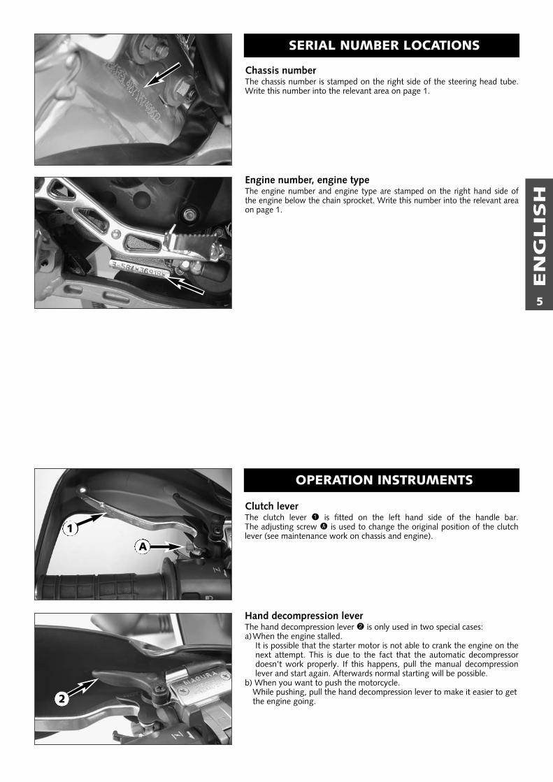
Chassis numberThe chassis number is stamped on the right side of the steering head tube.Write this number into the relevant area on page 1.
Engine number, engine typeThe engine number and engine type are stamped on the right hand side ofthe engine below the chain sprocket. Write this number into the relevant areaon page 1.
Clutch leverThe clutch lever 1 is fitted on the left hand side of the handle bar. The adjusting screw A is used to change the original position of the clutchlever (see maintenance work on chassis and engine).
Hand decompression leverThe hand decompression lever 2 is only used in two special cases:a)When the engine stalled.
It is possible that the starter motor is not able to crank the engine on thenext attempt. This is due to the fact that the automatic decompressordoesn’t work properly. If this happens, pull the manual decompressionlever and start again. Afterwards normal starting will be possible.
b) When you want to push the motorcycle.While pushing, pull the hand decompression lever to make it easier to getthe engine going.
SERIAL NUMBER LOCATIONS
OPERATION INSTRUMENTS
A
1
2

EN
GLIS
H
6
Hand brake leverThe hand brake lever 1 is mounted on the handlebar on the right andactuates the front wheel brake.The adjusting screw B is used to change theoriginal position of the hand brake lever (see maintenance work on chassisand engine).
Choke leverIf the choke lever 2 is pulled backwards, a bore will be opened in the car-buretor through which the engine may draw in additional fuel. This produ-ces a „rich“ fuel/air mixture necessary for cold start. If the choke lever ispushed forward up to the stop, the bore will be closed again. In this posi-tion the choke cable must have a play of approx. 2 mm.
Ignition lock with 3 switch positionsSwitch positions of ignition lock
Ignition off, (engine can't be started)
Ignition on, (engine can be started)
Ignition off, handlebar blockedTo switch the ignition to position turn the ignition key to position
and firmly press it into the lock. Turn the handlebar all the way tothe left, then turn the ignition key to the left.
The ignition key can be withdrawn in position and .
1
2
B

EN
GLIS
H
7
Multi-functional digital speedometer The universal instrument is divided into 3 parts.Use the MODE and SET 1 button to change the display and the basic set-tings in the display.Display 2 shows all of the information that may be of interest to you. 5display modes can be selected with the MODE button.
The indicator lamps 3 provide additional information on the motorcycle'srunning condition.
DisplayTESTWhen you switch on the ignition, all of the display elements will light up for1 second for the function test.
WS (wheel size)The display will change and show the diameter of the front wheel in inchesfor 1 second (WS = wheel size).Then the CLOCK mode will be displayed, or the mode that was activewhen the ignition was switched off.
CLOCKYou will recognize the CLOCK display by the blinking dots between thehours and minutes. It displays the speed, temperature of the cooling liquidand the clock.To switch to the next display mode, press the MODE button.
ODOThe speed, temperature of the cooling liquid and the total kilometers ormiles traveled are shown in the ODO mode.To switch to the next display mode, press the MODE button.
TRIP 1The TRIP 1 mode shows the speed, the temperature of the cooling liquidand the trip odometer 1.To switch to the next display mode, press the MODE button.
TRIP 2The TRIP 2 mode shows the speed, the temperature of the cooling liquidand the trip odometer 2.To switch to the next display mode, press the MODE button.
TRIP FThe TRIP F (fuel) mode shows the speed, the temperature of the coolingliquid and the distance traveled since reaching the low-fuel mark (the low-fuel indicator lamp will blink). To return to the UHR mode, press the MODE button.
1 2 3
TEST
WS
ODO
CLOCK
TRIP 1
TRIP 2
TRIP F

EN
GLIS
H
8
Setting options in the displayKILOMETERS OR MILES.You can have the speed and distance shown in kilometers or miles in thedisplay. The display can be adapted to the respective country on long-distance trips.To switch from kilometers to miles, switch on the ignition and press theMODE 1 button for approx. 10 seconds. The km/h display will switch tomph. The speed and the stored distances will be converted and displayed inmiles.To return to kilometers, proceed as described above.
CLOCKSwitch on the ignition and change to the CLOCK mode.Simultaneously press MODE 1 and SET 2. The numbers on the clock willstart to blink. Use the MODE button to set the hours and the SET button toset the minutes. The press the MODE and SET buttons simultaneously.
NOTE:0:00 will be displayed if the clock is not supplied with electricity. This can becaused by a defective fuse or a fault in the board electric system (seeTroubleshooting).
TRIP 1The trip meter 1 runs continuously and counts up to 999.9. It can be usedto measure the length of a certain route on a trip or the distance betweentwo refueling stops.To return the trip meter 1 to zero, switch on the ignition, change to theTRIP 1 mode and press the SET button.
RESETTING TRIP 2 The trip meter 2 runs continuously and counts up to 999.9. It can be usedsimilarly to TRIP 1 or together with a switch available as an accessory (seebelow) for trips according to a roadbook.To return the trip meter 2 to zero, switch on the ignition, change to theTRIP 2 mode and press the SET button.
NOTEA Tripmaster switch (Part no. 582.14.069.044) is available as an accessoryand enhances the trip meter 2 functions. You can correct the displayedroute by increasing or decreasing in increments of 0.1. For example, if youhave taken the wrong road when driving according to a roadbook, you caneasily correct the display to correspond to the roadbook again. It can alsobe used to change the display modes. The switch is mounted on the hand-lebars so that you can keep your hands on the handlebars.
TRIP FWhen the fuel level reaches the reserve mark, the display will automaticallyswitch to TRIP F and begin to count (no matter which display mode wasactive before). At the same time, the fuel warning lamp will start to blink.You will still have enough reserve fuel for at least 35 kilometers.After refueling, it will take approx. 3 minutes for TRIP F to automaticallyreset to 0 and return to the previous display mode.
NOTE:To use up the reserve fuel in the tank, move the fuel cock to the RES posi-tion by hand.
10 sec1
1
2
2
2

EN
GLIS
H
9
Cooling liquid temperature display The temperature display 1 is shown in 7 bars. The more bars that light up,the hotter the cooling liquid. When the lowest bar lights up, the coolingliquid has reached a temperature of approx. 50°C. Each additional barrepresents 10°C more. When the upper bar lights up, all of the bars willstart to blink and the red warning lamp 2 will light up.
� WARNING �POSSIBLE CAUSES FOR AN INCREASE IN TEMPERATURE, CAUSING THE RED WARNING LIGHTFOR THE COOLING LIQUID TEMPERATURE TO LIGHT UP (ALSO SEE PAGE 36):– DRIVING TOO SLOWLY AND DRIVING WITH A HEAVY LOAD AT HIGH AIR TEMPERATURES– NOT ENOUGH COOLING LIQUID IN THE SYSTEM– THE VENTILATOR ON THE LEFT RADIATOR IS NOT RUNNING– IMPROPER USE OF THE CLUTCH WHEN DRIVING SLOWLY
Indicator lamps
The green indicator lamp will blink in the blinker rhythm when theblinker is switched on.NOTE:The indicator lamp will blink slower when a blinker is broken.
The green indicator lamp will light up when the gearbox is in anidling position.
The blue indicator lamp will light up when the high beams areswitched on.
The red warning light will light up when the cooling liquid has rea-ched a temperature of approx. 110°C.
The orange warning light will start to blink when the fuel level hasreached the reserve mark. At the same time the display will auto-matically change to TRIP F (see TRIP F).
This warning light has no function.
This indicator lamp has no function.
TachometerThe tachometer 3 shows the engine speed in revolutions per minute (rpm).Do not push the engine into the red zone, which begins at 8500 rpm.
110°C (230°F)100°C (212°F)90°C (194°F)80°C (176°F)70°C (158°F)60°C (140°F)50°C (122°F)
1
2
3

EN
GLIS
H
10
Combination switchThe rocker switch LIGHTS 1 actuates the high beam or low beam.
= High-beam light
= Low-beam light
The indicator switch 2 returns to central position after actuation.Press flasher switch towards switch housing to switch off the flasher.
The horn is sounded with button 3.
The light signal (high beam) is actuated with button 4.
Starter tip switch, emergency OFF tip switch, light switchUse the starter tip switch 5 to operate the electric starter.
The light switch has 3 positions:
= Light off
= Parking light on
= Headlight on
The emergency off switch 6 is provided for emergency situations andshould not be used to switch off the engine.The engine is ready for operation in position (ignition circuit and startercircuit are switched on).The engine cannot be started in position (ignition circuit and startercircuit are interrupted).
Filler cap
To open: Turn the filler cap 7 anti-counterclockwise.
To close: Screw on the filler cap clockwise.
Fuel tapsThe motorcycle is equipped with a fuel taps and 2 auxiliary fuel cocks. A fuel pump pumps the fuel from the tank to the carburetor.The auxiliary fuel cocks on the inside of the tank are connect the two tankchambers via a line. They must always be open.Open position: turn the knob to the limit in a counter-clockwise direction.
NOTE:Only close the two auxiliary fuel cocks when you remove the fuel tank (seechapter on removing the tank).
1
1
23
6
5
4
7

EN
GLIS
H
11
Fuel tap A on the left side of the tank has 3 positions.OFF In this position the fuel tap is closed. No fuel can flow to the carburetor.ON When using the motorcycle, the twist grip must be set to the ON
position. Now fuel can flow to fuel pump. In this position the tankempties down to the fuel reserve of approx. 3,5 liters (0,9 US gallone).
RES The reserve, approximately 3,5 liters (0,9 US gallone), cannot be tap-ped until the twist grip is turned to the RES position. Fill the tank assoon as possible and remember to turn the twist grip back to the ONposition so that you will have backup fuel next time, too.
NOTE:The fuel tap must be open during operation. The fuel tap must be closed forparking.
Shift leverThe shift lever is mounted on the left side of the engine. The position of thegears is shown in the illustration. Neutral, or the idle speed, is located bet-ween first and second gear.
KickstarterThe kickstarter is mounted on the left side of the engine. Its upper part canbe swivelled.
Foot brake pedalThe foot brake pedal is located in front of the right footrest. Its basic posi-tion can be adjusted to your seat position (see maintenance work).
2,3,4,5
1
N
NO
OFF
RES
FUE
L
NO
OFF
RES
FUE
L
NO
OFF
RES
FUE
L
OFF ON RES
A

EN
GLIS
H
12
Compression damping of fork The compression damping is to be set at the lower end of the fork tubes. Itonly regulates the degree of damping during compression.Remove closingcap A. By using the knob 1 (COM), the degree of damping of the com-pression can be adjusted. Turn the knob clockwise to increase damping,turn it counterclockwise to reduce damping during compression.
BASIC SETTING– turn rotary knob clockwise as far as it will go– turn it back counter-clockwise by as many clicks as are specified for the
relevant type of fork
WP 1418X728 . . . . . . . .14 clicks
Rebound damping of forkThe rebound damping is to be set at the upper end of the fork tubes. It onlyregulates the degree of damping during rebounding.By using the knob 2 (REB), the degree of damping of the rebound can beadjusted. Turn the knob clockwise to increase damping, turn it counter-clockwise to reduce damping during rebounding.
BASIC SETTING– turn rotary knob clockwise as far as it will go– turn it back counter-clockwise by as many clicks as are specified for the
relevant type of fork
WP 1418X728 . . . . . . . .14 clicks
Compression damping of shock absorberWith the knob 3 the degree of damping of the compression can be adju-sted to 7 positions. Turn the knob counterclockwise to increase damping,turn it clockwise to reduce damping during compression.
BASIC SETTINGWP 0118X726 . . . . . . . .position 6
Rebound damping of shock absorberWith the setting wheel 4 the degree of damping of the rebound can beadjusted to 11 positions. Turn the knob to the left side to increase damping,turn it to the right side to reduce damping during rebounding.
BASIC SETTING:WP 0118X726 . . . . . . . .position 7
Baggage carrierThe baggage carrier may be loaded with up to 10 kg. The two lateral hoopsserve as handles for the passenger
1
2
A
3
4

EN
GLIS
H
13

EN
GLIS
H
14
Instructions for initial operation– Verify that your KTM dealer performed the PREPARATION
OF VEHICLE jobs (see Customer Service Manual).– Read the entire manual carefully before your first drive.– Enter the chassis, engine and key numbers on page 1.– Familiarize yourself with the operating elements.– Adjust the foot brake pedal to the most comfortable positi-
ons for you.– Make the basic settings on the multi-functional digital spee-
dometer.– Get used to handling the motorcycle on an empty car park,
before starting on a longer drive. Also try to drive as slowlyas possible and in standing position, to improve your feelingfor the vehicle.
– Do not drive along off-road tracks which go beyond yourability and experience.
– Hold the handlebar with both hands and leave your feet onthe foot rests while driving.
– Remove your foot from the foot brake pedal when you arenot braking. If the foot brake pedal is not released the brakepads rub continuously and the braking system is overhea-ted.
– You may only be accompanied by a passenger if yourmotorcycle is fitted and registered for such purposes. Thepassenger must hold tight to the brackets or hold on to thedriver during the drive, with his feet on the passenger footrests.
– Do not make any alterations to the motorcycle and alwaysuse ORIGINAL KTM SPARE PARTS. Spare parts from othermanufacturers can impair the safety of the motorcycle.
– New tires have a smooth surface and must be run in. Forthis purpose, carefully ride the motorcycle at moderatespeed, tilting the vehicle at different angles so that the sur-face is evenly roughened. Tires will not display their full gripcharacteristics before they are properly run in.
– Motorcycles are sensitive to alterations in the distribution ofweight. If you are taking luggage with you, this should besecured as close as possible to the middle of the vehicle; dis-tribute the weight evenly between the front and rear wheel.Never exceed the maximum permissible laden weight andthe axle weights. The maximum permissible laden weight ismade up of the following components:– Motorcycle ready for operation and tank full– Luggage– Driver and passenger with protective clothing and helmet.
– Pay attention to running in instructions.
Running in Even finely machined surfaces of engine parts have roughersurfaces than parts that slide on each other for a long time.Therefore, every engine must be run in. For this reason, do notdemand maximum performance from the engine for the first100 kilometers. The vehicle must be run in at low, changingperformance level for the first 1000 KM (620 miles). The maxi-mum number of revolutions per minute must not go exceed4800 rpm. Do not accelerate the engine up to the red mark onthe tachometer (8500 r.p.m.) during a running-in period of1000 km. Exceeding the above listed rotations as well as pus-hing high rpm when the engine is cold will have an adverseeffect on the life of your engine.
� WARNING �– WEAR SUITABLE CLOTHING WHEN DRIVING A MOTORCYCLE. CLEVER
KTM DRIVERS ALWAYS WEAR A HELMET, BOOTS, GLOVES AND AJACKET, REGARDLESS OF WHETHER DRIVING ALL DAY OR JUST FOR ASHORT TRIP. THE PROTECTIVE CLOTHING SHOULD BE BRIGHTLYCOLOURED SO THAT OTHER USERS OF THE ROADS CAN SEE YOU ASEARLY AS POSSIBLE. YOUR PASSENGER OF COURSE WILL ALSO NEEDSUITABLE PROTECTIVE CLOTHING.
– ALWAYS TURN ON THE LIGHT MAKE SURE THAT OTHER DRIVERSBECOME AWARE OF YOU AS EARLY AS POSSIBLE.
– DO NOT DRIVE AFTER HAVING CONSUMED ALCOHOL.– ONLY USE ACCESSORIES THAT HAVE BEEN RELEASED BY KTM. FOR
EXAMPLE, FRONT PANELLING CAN IMPAIR THE DRIVING PROPERTIES OFTHE MOTORCYCLE. CASES, EXTRA TANKS ETC. CAN ALTER THE WEIGHTDISTRIBUTION AND THUS ALSO IMPAIR THE VEHICLE’S DRIVING PRO-PERTIES.
– THE FRONT AND REAR WHEEL ARE ONLY ALLOWED TO BE TIRED WITHTIRES THAT HAVE THE SAME PROFILE TYPE.
– OBSERVE THE TRAFFIC REGULATIONS, DRIVE DEFENSIVELY AND TRYINGTO LOOK AHEAD AS FAR AS POSSIBLE SO THAT ANY HAZARDS CAN BERECOGNIZED AS EARLY AS POSSIBLE.
– ADJUST YOUR DRIVING SPEED ACCORDING TO THE CONDITIONS ANDYOUR DRIVING SKILLS.
– DRIVE CAREFULLY ON UNKNOWN ROADS– REPLACE THE HELMET VISOR RESPECTIVELY GOGGLE GLASSES IN PLENTY
OF TIME. WHEN LIGHT SHINES DIRECTLY ON SCRATCHED VISOR ORGOGGLES, YOU WILL BE PRACTICALLY BLIND.
– NEVER LEAVE YOUR MOTORCYCLE WITHOUT SUPERVISION AS LONG ASTHE ENGINE IS RUNNING.
GENERAL TIPS AND WARNINGS FOR STARTING THE MOTORCYCLE

EN
GLIS
H
15
Check the following before each startWhen you start off, the motorcycle must be in a perfect technical condition. Forsafety reasons, you should make a habit of performing an overall check of yourmotorcycle before each start.The following checks should be performed:
1 CHECK THE OIL LEVELInsufficient oil results in premature wear and consequently to enginedamage.
2 FUELCheck that there is sufficient fuel in the tank; when closing the filler cap,check that the tank venting hose is free of kinks.
3 CHAINA loose chain can fall off; an extremely worn chain can tear, and insuffi-cient lubrication can result in unnecessary wear to the chain and rearsprockets.
4 TIRESCheck for damaged tires. Tires showing cuts or dents must be replaced.The tread depth must comply with the legal regulations. Also check theair pressure. Insufficient tread and incorrect air pressure reduce the dri-ving performance.
5 BRAKESCheck correct functioning of the braking system. Check for sufficientbrake fluid in the reservoir. The reservoirs have been designed in such away that brake fluid does not need to be refilled even when the brakepads are worn. If the level of brake fluid falls below the minimum value,this indicates a leak in the braking system or completely worn out brakepads. Arrange for the braking system to be checked by a KTM specialistgarage, as complete failure of the braking system can be expected.Also check the state of the brake hoses and the thickness of the brakelinings.Check free travel at hand brake lever and foot brake pedal.
� WARNING �IF THE RESISTANCE IN THE HAND BRAKE LEVER OR FOOT BRAKE PEDAL FEELS “SPONGY”(TOO MUCH GIVE), THIS IS AN INDICATION THAT SOMETHING IS WRONG WITH THEBRAKE SYSTEM. DON’T RIDE YOUR MOTORCYCLE ANYMORE WITHOUT FIRST HAVING THEBRAKE SYSTEM LOOKED OVER BY A KTM DEALER.
6 CABLESCheck correct setting and easy running of all control cables.
7 COOLING LIQUIDCheck the level of cooling liquid when the engine is cold.
8 ELECTRICAL SYSTEMCheck headlight, parking light, tail light, brake light, flashers, indicatorlamps and horn for faultless operation.
9 LUGGAGEIf you are taking luggage with you, check that this is securely fastened.
DRIVING INSTRUCTIONS

EN
GLIS
H
16
Starting when the engine is cold1 Open the fuel tap.2 Turn on the ignition (ignition key position: ).3 Switch the gear to neutral (green lamp 1 lights).4 Switch on the emergency off switch 2.5 Operate the choke lever 3. 6 Operate the starter tip switch 4 without accelerating.7 If the engine starts, push the choke lever back a little bit, as soon as the
engine runs unevenly.8 Swing up the centerstand9 Switch on the light before setting off.
� WARNING �DO NOT START THE ENGINE AND ALLOW IT TO IDLE IN A CLOSED ROOM. EXHAUSTFUMES ARE POISONOUS AND CAN CAUSE LOSS OF CONSCIOUSNESS AND DEATH. ALWAYSPROVIDE ADEQUATE VENTILATION WHILE THE ENGINE IS RUNNING.
! CAUTION !– MAXIMUM PERIOD FOR CONTINUOUS STARTING: 5 SECONDS. WAIT AT LEAST 5
SECONDS BEFORE TRYING AGAIN.– DON’T RIDE YOUR MOTORCYCLE WITH FULL LOAD AND DON’T REV ENGINE WHEN
COLD. BECAUSE THE PISTON IS WARMING UP FASTER THAN THE WATER COOLEDCYLINDER, IT CAN CAUSE ENGINE DAMAGE. ALWAYS KEEP IN MIND THAT THE ENGINESHOULD BE WARMED UP WITH SMALL LOAD AT MEDIUM R.P.M.
IF THE ENGINE IS DOES NOT CRANK WHEN YOU ACTUATE THE STARTER TIP SWITCH:– the transmission is switched to idle– Check if the emergency OFF switch is on– Check if the ignition is on– the headlight is on.
– If this is not the case, the battery is discharged– If the lights are on, proceed as described in the „Trouble-shooting“
section or contact a KTM dealer.
IF THE ENGINE CRANKS BUT DOES NOT START, WHEN YOU ACTUATETHE STARTER TIP SWITCH:– Check if the fuel tap is open– Check if the choke lever has been operated– Check if sufficient fuel is in the tank
– If this is not the case, refill the tank– if sufficient fuel is in the tank, proceed as described in the „Trouble-
shooting“ section or contact a KTM dealer.
NOTE:THIS MOTORCYCLE IS EQUIPPED WITH A SAFETY STARTER SYSTEM. THE ENGINE CAN ONLYBE STARTED WHEN THE TRANSMISSION IS SWITCHED TO IDLE OR THE CLUTCH LEVER ISPULLED, RESPECTIVELY.
THE ELECTRIC STARTER DOESN’T CRANK THE ENGINE WHEN THE STAR-TER TIP SWITCH IS OPERATED EVEN THOUGH SUFFICIENT ELECTRICCURRENT IS AVAILABLE:– Pull the hand decompression lever 5, start and release the lever.
Starting when the engine is warm or hot1 Open the fuel tap.2 Turn on the ignition (ignition key position: ).3 Switch the gear to neutral (green lamp 1 lights).4 Switch on the emergency off switch 2.5 Operate the starter switch 4 without accelerating.6 Swing up the centerstand7 Switch on the light before setting off.
What to do when the engine is „flooded”The throttle must be fully opened when starting. If necessary change sparkplug.
1
2
4
5 3

EN
GLIS
H
17
Starting the engine with the kickstarter Be sure to kick up the side or center stand before you start theengine to avoid any damage.Start as described above, thenpush the kickstarter hard all the way.
� WARNING �– IF YOU WANT TO START THE ENGINE, MAKE SURE THAT YOU ALWAYS
PUT ON STURDY MOTORCYCLE BOOTS IN ORDER TO AVOID INJURIES.YOU MIGHT SLIP OFF THE KICKSTARTER, OR THE ENGINE MAY KICKBACK THE KICKSTARTER.
– ALWAYS KICK KICKSTARTER BRISKLY ALL THE WAY WITHOUT OPENINGTHE THROTTLE. KICKING THE KICKSTARTER WITH NOT ENOUGHMOMENTUM, AND AN OPENED THROTTLE GRIP INCREASE THE KICK-BACK HAZARD.
Starting offPull the clutch lever. Put the engine into first gear, slowlyrelease the clutch lever and open throttle at the same time.
� WARNING �BEFORE YOU START OFF, CHECK THAT THE CENTER STAND HAS BEENSWUNG RIGHT UP TO THE TOP. IF THE STAND DRAGS ON THE GROUND,THE MOTORCYCLE CAN GO OUT OF CONTROL.
Shifting/RidingYou are now in first gear, refered to as the drive or uphill gear.Depending on the conditions (traffic, road gradient, etc.), youcan shift to a higher gear. Close throttle, at the same time pullclutch lever and shift to the next higher gear. Let clutch levergo again and open throttle. If you turned on the choke, makesure you turn it off again as soon as engine is warm.When you reach full speed through turning the throttle grip allthe way, turn throttle back to 3/4; the speed hardly decreasesalthough the engine will use less gas. Never open the throttlewider than the engine can handle. Excessive turning of thethrottle grip will increase full consumption. By shifting down, use the brakes if necessary and close throttleat the same time. Pull clutch lever and shift down to the nextgear. Let clutch lever go slowely and open throttle or shiftdown again. If the engine is killed f.ex. at a crossing, simplypull the clutch lever and start. It is not necessary to switch thegear to NEUTRAL.
� WARNING �– AVOID ABRUPT LOAD CYCLES IN CURVES AND ON WET OR SLIPPERY
ROADS. OTHERWISE, THE MOTORCYCLE COULD EASILY GET OUT OFCONTROL.
– NEVER TURN THE IGNITION KEY TO POSITION OR WHILE THEMOTORCYCLE IS MOVING.
– DO NOT TRY TO CHANGE THE SETTINGS WHILE DRIVING. YOURATTENTION WILL BE DISTRACTED FROM THE TRAFFIC AND MAY CAUSEYOU TO LOSE CONTROL OF YOUR MOTORCYCLE.
– AFTER FALLING WITH THE MOTORCYCLE, CHECK ALL FUNCTIONSTHOROUGHLY BEFORE STARTING UP OPERATIONS AGAIN.
! CAUTION !– HIGH RPM RATES WHEN THE ENGINE IS COLD HAVE AN ADVERSE
EFFECT ON THE LIFE OF YOUR ENGINE. WE RECOMMEND YOU RUNTHE ENGINE IN A MODERATE RPM RANGE FOR A FEW MILES GIVING ITA CHANCE TO WARM UP. AFTER THAT NO FURTHER PRECAUTIONS INTHIS RESPECT NEED BE TAKEN.
– SHIFT TO THE NEXT HIGHER GEAR BY 8500 RPM AT THE LATEST.– NEVER HAVE THE THROTTLE WIDE OPEN WHEN CHANGING DOWN TO A
LOWER GEAR. THE ENGINE WILL OVERSPEED, DAMAGING THE VALVES.IN ADDITION, THE REAR WHEEL BLOCKS SO THAT THE MOTORCYCLECAN EASILY GET OUT OF CONTROL.
– IF THE RED COOLING LIQUID TEMPERATURE LAMP LIGHTS UP WHILEYOU ARE DRIVING, THIS INDICATES COOLING SYSTEM TROUBLE. IMME-DIATELY STOP AND TURN OFF THE ENGINE. DRIVING WITH THE WAR-NING LAMP ON WILL CAUSE ENGINE DAMAGE.– PLACE A CLOTH ON THE RADIATOR CAP. OPEN THE CAP SLOWLY,
SO THE EXCESS PRESSURE IN THE COOLING SYSTEM CAN ESCAPE.CAUTION SCALDING HAZARD! - AND CHECK THE COOLINGLIQUID LEVEL.
– DO NOT DRIVE ON, UNTIL THERE IS SUFFICIENT LIQUID IN THE COO-LING SYSTEM. HOWEVER, CALL ON ONE OF KTM’S DEALERS ASSOON AS POSSIBLE IN ORDER TO HAVE THE DEFECT REMEDIED.
– IF ANY ABNORMAL VIBRATIONS OCCUR WHILE DRIVING, CHECK THATTHE ENGINE FASTENING SCREWS ARE TIGHT.
– IN THE EVENT THAT, WHILE RIDING YOUR MOTORCYCLE, YOU NOTICEANY UNUSUAL OPERATION-RELATED NOISE, STOP IMMEDIATELY, TURNTHE ENGINE OFF, AND CONTACT AN AUTHORIZED KTM DEALER.
BrakingClose throttle and apply the hand and foot brakes at the sametime. When driving on sandy, wet or slippery ground usemainly the rear wheel brake. Always brake with feeling,blocking wheels can cause you to skid or fall. Also changedown to lower gears depending on your speed.When driving downhill, use the braking effect of the engine.Change down one or two gears but do not overspeed theengine. In this way, you will not need to brake so much andthe brakes will not overheat.
� WARNING �– DELAYED BRAKE ACTION MUST BE EXPECTED DUE TO WET BRAKE DISKS
DURING RAINY WEATHER OR AFTER CLEANING OF THE MOTORCYCLE.IN THIS CASE, REPEATEDLY APPLY THE BRAKES UNTIL THEY ARE DRY.
– DELAYED BRAKE ACTION CAN ALSO OCCUR ON SALTED OR DIRTYROADS. IN THIS CASE, REPEATEDLY APPLY THE BRAKES TO REMOVE THEDIRT.
– WHEN YOU BRAKE, THE BRAKE DISCS, BRAKE PADS, BRAKE CALIPERAND BRAKE FLUID HEAT UP. THE HOTTER THESE PARTS GET, THE WEA-KER THE BRAKING EFFECT. IN EXTREME CASES, THE ENTIRE BRAKINGSYSTEM CAN FAIL.
– DIRTY BRAKE DISCS CAUSE INCREASED TEAR OF BRAKE PADS ANDBRAKE DISCS.

EN
GLIS
H
18
Stopping and parkingApply the brakes fully and put the engine into neutral. To stop the engine,switch off the ignition. Close fuel tap. Park on solid ground and lock thevehicle.
� WARNING �– MOTORCYCLE ENGINES PRODUCE A GREAT AMOUNT OF HEAT WHILE RUNNING. THE
ENGINE RADIATORS, EXHAUST, EXHAUST SYSTEM, BRAKE DISCS, AND SHOCK ABSOR-BERS CAN BECOME VERY HOT. DO NOT TOUCH ANY OF THESE PARTS AFTER OPERA-TING THE MOTORCYCLE, AND TAKE CARE TO PARK IT WHERE PEDESTRIANS ARE NOTLIKELY TO TOUCH IT AND GET BURNED.
– NEVER PARK YOUR MOTORCYCLE IN PLACES WHERE THERE EXIST FIRE HAZARDS DUETO DRY GRASS OR OTHER EASILY FLAMMABLE MATERIALS.
! CAUTION !– PARK YOUR MOTORCYCLE, SO THAT IT RESTS STABLY ON THE SIDESTAND (HARD
GROUND, LEVEL SURFACE) AND CAN’T TIP OVER.– DO NOT LEAVE THE PARKING LIGHT ON FOR MORE THAN THREE HOURS WITH THE
ENGINE OFF. OTHERWISE YOU WILL NOT BE ABLE TO START THE ENGINE WITH THEELECTRIC STARTER.
– THE FUEL TAPS MUST ALWAYS BE CLOSED WHEN PARKING THE MOTORCYCLE.OTHERWISE THE CARBURETOR CAN OVERFLOW AND FUEL COULD FLOW INTO THEENGINE.
– ALWAYS TAKE OUT THE IGNITION KEY WHEN PARKING YOUR MOTORCYCLE SO THATIT CANNOT BE USED BY UNAUTHORIZED PERSONS.
NOTE REGARDING THE CENTER STAND:We advice the following procedure to place the motorcycle on the centerstand as effortlessly as possible:a) press main stand to ground using foot,b) swing out kickstarter and pull motocycle backwards at an angle as illustrated(see illustration).Make sure that the ground is solid and that your motorcycle is standingsecurely.
RefuelingThe LC4 engine needs premium gasoline with an octane number of 95 orhigher.
! CAUTION !– USE UNLEADED PREMIUM GRADE GASOLINE (95 OCTANES). NEVER USE ANY
GASOLINE HAVING LESS THAN 95 OCTANES BECAUSE IT MAY DAMAGE THE ENGINE.– BE CAREFUL NOT TO LET FUEL DRIP ON THE PAINTED PARTS, WIPE UP ANY SPILLS IMME-
DIATELY. THE FUEL WILL DISCOLOR THE CLEAR COAT AND MAKE IT TURN YELLOW.
Fuel expands when its temperature rises. Therefore do not fill the tank tothe top (see fig.).
� WARNING �GASOLINE IS HIGHLY FLAMMABLE AND POISONOUS. EXTREME CAUTION SHOULD BE USEDWHEN HANDLING GASOLINE. DO NOT REFUEL THE MOTORCYCLE NEAR OPEN FLAMES ORBURNING CIGARETTES. ALWAYS SWITCH OFF THE ENGINE BEFORE REFUELLING. BECAREFUL NOT TO SPILL GASOLINE ON THE ENGINE OR EXHAUST PIPE WHILE THE ENGINE ISHOT. WIPE UP SPILLS PROMPTLY. IF GASOLINE IS SWALLOWED OR SPLASHED IN THE EYES,SEEK A DOCTOR’S ADVICE IMMEDIATELY.
35 mm

EN
GLIS
H
19

EN
GLIS
H
20
PERIODIC MAINTENANCE SCHEDULE1. Service
after1000 km
2. Service after5000 km, then
every 5000 km oronce a year
IF MOTORCYCLE IS USED FOR COMPETITION 5000 KM SERVICE SHOULD BE CARRIED OUT AFTER EVERY RACE!SERVICE INTERVALLS SHOULD NEVER BE EXCEED BY MOOR THAN 500 KM.MAINTENANCE WORK DONE BY KTM AUTHORISED WORKSHOPS IS NOT A SUBSTITUTE OF CARE AND CHECKS DONE BY THE RIDER!
A washed motorcycle can be checked more quickly which saves money!
Change engine oil, oil filter, and fine filter ● ●
Clean oil screens and magnet of drain plug ● ●
Check oil lines for damage and kink-less arrangement ● ●
Check and adjust spark plug, replace it every 10,000 km ●
Check and adjust valve clearance ● ●
Check engine fastening screws for tight fit ● ●
Make sure all engine screws accessible from the outside are screwed tight ● ●
Check carburetor connection boots for cracks and leaks ●
Check idle setting ● ●
Check bleeder hoses for damage and kink-free arrangement ● ●
Check cooling system for leaks, antifreeze protection ● ●
Check radiator fan for proper operation ●
Check exhaust system for leaks and suspension ● ●
Check actuating cables for damage, smooth operation, and kink-less arrangement,adjust and lubricate them ● ●
Clean air filter and air filter box ●
Check cables for damage and kink-less arrangement ●
Check headlamp adjustment ●
Check electrical system for function (low/high beams, stop light, turn indicators,headlamp flasher, ● ●
tell-tale lamps, speedometer illumination, horn, side-stand switch, clutch switch, emergency-off switch)Make sure all screws and nuts are tight. ● ●
Check brake fluid level, lining thickness, and brake discs ● ●
Check brake lines for damage and leaks ● ●
Check/adjust smooth operation, free travel of handbrake/footbrake levers ● ●
Check screws of brake system for tight fit ● ●
Check suspension strut and fork for leaks and proper operation ● ●
Check O-ring of suspension strut for wear ●
Clean fork dust sleeves ●
Bleed fork legs ● ●
Check swinging-fork pivot ● ●
Check/adjust steering-head bearing ● ●
Lubricate reversing lever ●
Check all chassis screws for tight fit (fork plates, fork leg, axle nuts/screws, ● ●
swinging-fork pivot, reversing lever, suspension strut)Check spoke tension and rim joint ● ●
Check tire condition and inflation pressure ● ●
Check chain and chain guides for wear, force fit and tension. ● ●
Check screws on pinion and chain sprocket for locking devices and a tight fit. ● ●
Lubricate chain ● ●
Check wheel bearings and jerk damper for play ●
IMPORTANT RECOMMENDED MAINTENANCE PROCEDURES TO BE PERFORMED BASED ON A SEPARATE SUPPLEMENTARY ORDER
Perform complete fork maintenance ●
Perform complete suspension strut maintenance ●
Perform complete reversing lever maintenance ●
Clean and lubricate steering-head bearing and sealing elements ●
Clean and adjust the carburetor ●
Treat the electrical contacts and switches with contact spray ●
Treat battery connections with contact grease ●
Change the brake fluid ●
WH
EELS
CH
ASS
ISBR
AK
ESA
DD
-ON
-PA
RTS
CARB
URET
OREN
GIN
E640 LC4 ADVENTURE
every 2 yearsor 20000 km
at leastonce a year

EN
GLIS
H
21
VITAL CHECKS AND CARE PROCEDURES TO BE CONDUCTED BY THE OWNER OR THE MECHANIC
Check oil level ●
Check brake fluid level ●
Check brake pads for wear ●
Check lighting system for proper operation ●
Check horn for proper operation ●
Lubricate and adjust actuating cables and nipples ●
Bleed fork legs in regular intervals ●
Remove and clean fork dust sleeves in regular intervals ●
Clean and lubricate chain as necessary ● ●
Check chain tension ● ● ●
Clean air filter and filter box (depending on the dirt accumulation) ●
Check tire pressure and wear ●
Check coolant level ●
Check fuel lines for leaks ●
Drain float chamber ●
Check all control elements for smooth running. ●
Check brake performance ● ●
Treat exposed metal components (except for the braking and exhaust ●
systems) with wax-based anti-corrosion agentsTreat ignition/steering lock and light switch with contact spray ●
Check all screws, nuts, and hose clamps for their tight fit ●
once a yearfor crosscountry use
after everycleaning
before eachstart

EN
GLIS
H
22
� WARNING �
MAINTENANCE AND ADJUSTING WORK MARKED WITH AN ASTERISK (*) REQUIRES EXPERT SKILLSAND TECHNICAL KNOW-HOW. FOR YOUR OWN SAFETY, ALWAYS HAVE SUCH WORK PERFORMED BYA SPECIALIZED KTM DEALER WHERE YOUR MOTORCYCLE WILL BE OPTIMALLY SERVICED BY APPRO-PRIATELY QUALIFIED SKILLED STAFF.
! CAUTION !– WHEN CLEANING THE MOTORCYCLE, DO NOT USE A HIGH PRESSURE CLEANING UNIT IF POSSIBLE, OTHERWISE WATER WILL PENETRATE THE BEARINGS, CAR-
BURETOR, ELECTRIC CONNECTORS ETC.– WHEN TRANSPORTING YOUR KTM, ENSURE THAT IT IS HELD UPRIGHT WITH RESTRAINING STRAPS OR OTHER MECHANICAL FASTENING DEVICES. IF THE
MOTORCYCLE SHOULD FALL OVER, FUEL CAN LEAK FROM THE CARBURETOR OR FUEL TANK– DO NOT USE TOOTHED WASHERS OR SPRING WASHERS WITH THE ENGINE FASTENING SCREWS, AS THESE WORK INTO THE FRAME PARTS AND KEEP WOR-
KING LOOSE. INSTEAD, USE SELF-LOCKING NUTS.– LET YOUR MOTORCYCLE COOL DOWN BEFORE BEGINNING ANY MAINTENANCE WORK IN ORDER TO AVOID GETTING BURNED.– PROPERLY DISPOSE OF OIL, GREASE, FILTERS, FUEL, CLEANSERS, BRAKE FLUID, COOLING LIQUID, ETC. OBSERVE THE REGULATIONS EFFECTIVE IN YOUR
COUNTRY. ALSO OBSERVE THE SAFETY REGULATIONS WHEN HANDLING THESE SUBSTANCES.– UNDER NO CIRCUMSTANCES MAY USED OIL BE DISPOSED OF IN THE SEWAGE SYSTEM OR IN THE OPEN COUNTRYSIDE. 1 LITER USED OIL CONTAMINATES
1,000.000 LITERS WATER.– IF YOU UNFASTEN SELF-LOCKING NUTS, YOU HAVE TO REPLACE THEM BY NEW ONES.– IF YOU UNFASTEN SCREWS AND NUTS SECURED BY LOCTITE, YOU HAVE TO REATTACH AND SECURE THEM IN THE SAME WAY. SEE TECHNICAL SPECIFICATI-
ONS - FASTENING TORQUES ON PAGE 48.
Tool setThe tool kit 1 is locted in the tool box under the right side cover.
Removing the seatRemove the collar screws 2 from the underside of the fender. Lift the rearof the seat, pull backwards, and unhook it from the oval-head screw 3.
To install the seat, hook the seat into the oval-head screw, set the rear portiondown on the frame, and slide it forward. If necessary, press down on thefront area of the seat so that the seat catches on the retaining bracket 4. Insert and tighten the collar screw.
MAINTENANCE WORK ON CHASSIS AND ENGINE
2
3
4
2
1

EN
GLIS
H
23
Checking and adjusting steering head bearing *Check steering head bearing for play periodicaly. To check this putmotorcycle on a stand so that the front wheel is off the ground. Now try tomove the fork forward and backward. To adjust, loosen the five clamp scr-ews 1 of the top triple clamp and turn steering stem bolt clockwise 2 untilthere is no more play. Don’t tighten the steering stem bolt all the way,otherwise the bearings will be damaged. With a plastic hammer, lightly rapon the triple clamp to avoid tension. Re-tighten the five clamp screws with15 Nm (11 ft.lb).
� WARNING �IF THE STEERING HEAD BEARING IS NOT ADJUSTED TO BE FREE OF PLAY, THE MOTORCYCLEWILL SHOW AN UNSTEADY DRIVING PERFORMANCE AND CAN GET OUT OF CONTROL.
! CAUTION !IF YOU DRIVE WITH PLAY IN THE STEERING HEAD BEARING FOR LONGER PERIODS, FIRST THEBEARINGS AND THEN THE BEARING SEATS IN THE FRAME WILL BE DESTROYED.
At least once a year, the steering head bearings should be greased(Motorex Long Therm 2000).
Bleeder screw front forkThe bleeder screws 3 should now and then be released a few turns to letoverpressure, if any, escape from the interior of the fork. To do this, placethe motorcycle on a stand with the front wheel lifted off the ground. Whenriding the motorcycle mainly on street, it will be enough to have this jobperformed in the course of the periodical maintenance service.
! CAUTION !EXCESSIVE PRESSURE IN THE INTERIOR OF THE FORK CAN CAUSE LEAKS IN THE FORK. IFYOUR FORK IS LEAKING, IT IS RECOMMENDED TO OPEN THE BLEEDER SCREWS BEFOREHAVING THE SEALS REPLACED.
Cleaning the dust sleeves of the telescopic forkThe dust-protection bellows 4 are to remove dust and coarse dirt particlesfrom the fork tube. However, after some time, dirt may also get in behindthe dust-protection bellows. If this dirt is not removed, the oil sealing ringslocated behind it may start to leak.Use a screwdriver to lever the dust-protection bellows out of the outertubes and slide them downward.
Clean dust-protection bellows, outer tubes, and fork tubes thoroughly, andoil them thoroughly with silicone spray or engine oil. Then, push dust-pro-tection bellows into the outer tubes by hand.
2
1
3
4
EN
GLIS
H
24
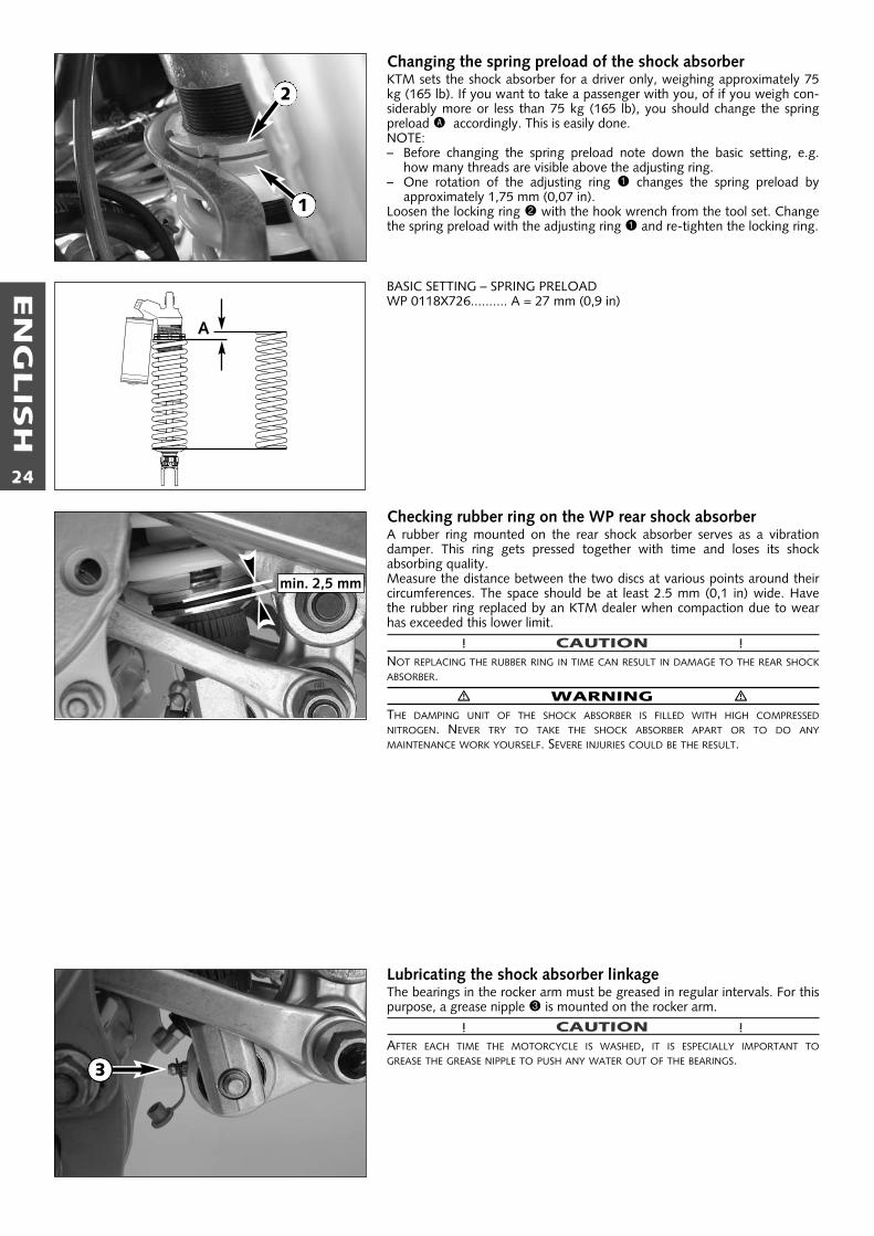
Changing the spring preload of the shock absorberKTM sets the shock absorber for a driver only, weighing approximately 75kg (165 lb). If you want to take a passenger with you, of if you weigh con-siderably more or less than 75 kg (165 lb), you should change the springpreload A accordingly. This is easily done.NOTE:– Before changing the spring preload note down the basic setting, e.g.
how many threads are visible above the adjusting ring.– One rotation of the adjusting ring 1 changes the spring preload by
approximately 1,75 mm (0,07 in).Loosen the locking ring 2 with the hook wrench from the tool set. Changethe spring preload with the adjusting ring 1 and re-tighten the locking ring.
BASIC SETTING – SPRING PRELOADWP 0118X726.......... A = 27 mm (0,9 in)
Checking rubber ring on the WP rear shock absorberA rubber ring mounted on the rear shock absorber serves as a vibrationdamper. This ring gets pressed together with time and loses its shock absorbing quality. Measure the distance between the two discs at various points around theircircumferences. The space should be at least 2.5 mm (0,1 in) wide. Havethe rubber ring replaced by an KTM dealer when compaction due to wearhas exceeded this lower limit.
! CAUTION !NOT REPLACING THE RUBBER RING IN TIME CAN RESULT IN DAMAGE TO THE REAR SHOCKABSORBER.
� WARNING �THE DAMPING UNIT OF THE SHOCK ABSORBER IS FILLED WITH HIGH COMPRESSEDNITROGEN. NEVER TRY TO TAKE THE SHOCK ABSORBER APART OR TO DO ANYMAINTENANCE WORK YOURSELF. SEVERE INJURIES COULD BE THE RESULT.
Lubricating the shock absorber linkageThe bearings in the rocker arm must be greased in regular intervals. For thispurpose, a grease nipple 3 is mounted on the rocker arm.
! CAUTION !AFTER EACH TIME THE MOTORCYCLE IS WASHED, IT IS ESPECIALLY IMPORTANT TOGREASE THE GREASE NIPPLE TO PUSH ANY WATER OUT OF THE BEARINGS.
A
min. 2,5 mm
1
2
3
EN
GLIS
H
25
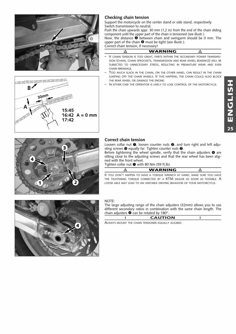
Checking chain tensionSupport the motorcycle on the center stand or side stand, respectively.Switch transmission to neutral.Push the chain upwards appr. 30 mm (1,2 in) from the end of the chain slidingcomponent until the upper part of the chain is tensioned (see illustr.)Now, the distance A between chain and swingarm should be 0 mm. Theupper part of the chain B must be tight (see illustr.).Correct chain tension, if necessary!
� WARNING �– IF CHAIN TENSION IS TOO GREAT, PARTS WITHIN THE SECONDARY POWER TRANSMIS-
SION (CHAIN, CHAIN SPROCKETS, TRANSMISSION AND REAR WHEEL BEARINGS) WILL BESUBJECTED TO UNNECESSARY STRESS, RESULTING IN PREMATURE WEAR AND EVENCHAIN BREAKAGE.
– TOO MUCH SLACK IN THE CHAIN, ON THE OTHER HAND, CAN RESULT IN THE CHAINJUMPING OFF THE CHAIN WHEELS. IF THIS HAPPENS, THE CHAIN COULD ALSO BLOCKTHE REAR WHEEL OR DAMAGE THE ENGINE.
– IN EITHER CASE THE OPERATOR IS LIKELY TO LOSE CONTROL OF THE MOTORCYCLE.
Correct chain tensionLoosen collar nut 1, loosen counter nuts 2, and turn right and left adju-sting screws 3 equally far. Tighten counter nuts 2. Before tightening the wheel spindle, verify that the chain adjusters 4 aresitting close to the adjusting screws and that the rear wheel has been alig-ned with the front wheel.Tighten collar nut 1 with 80 Nm (59 ft.lb).
� WARNING �IF YOU DON’T HAPPEN TO HAVE A TORQUE WRENCH AT HAND, MAKE SURE YOU HAVETHE TIGHTENING TORQUE CORRECTED BY A KTM DEALER AS SOON AS POSSIBLE. ALOOSE AXLE MAY LEAD TO AN UNSTABLE DRIVING BEHAVIOR OF YOUR MOTORCYCLE.
NOTE:The large adjusting range of the chain adjusters (32mm) allows you to usedifferent secondary ratios in combination with the same chain length. Thechain adjusters 4 can be rotated by 180°.
! CAUTION !ALWAYS MOUNT THE CHAIN TENSIONER EQUALLY ALIGNED.
A
B
15:4516:42 A = 0 mm 17:42
30mm
2
3
4
1
4

EN
GLIS
H
26
Chain maintenanceFor long chain life, good maintenance is very important. X-ring chainsrequire only modest maintenance. The best way is to use lots of water, butnever use brushes or solvents. After letting the chain dry, you can use aspecial X-ring chain spray (Motorex Chainlube Racing).
� WARNING �NO LUBRICATION IS ALLOWED TO REACH THE REAR TIRE OR THE BRAKE DISK, EITHERWISETHE ROAD ADHERENCE AND THE REAR WHEEL BRAKING EFFECTS WOULD BE STRONGLYREDUCED AND THE MOTORCYCLE COULD EASILY GET OUT OF CONTROL.
! CAUTION !WHEN MOUNTING THE CHAIN JOINT, THE CLOSED SIDE OF THE SAFETY DEVICE MUSTPOINT IN RUNNING DIRECTION.
Also check sprockets and chain guides for wear, and replace if necessary.
Chain wearIn order to check the chain wear, regard the following instructions:Shift the gear into idling and pull the upper chain strand with approx. 10-15kilogramm (33 lb) upwards (see figure). Now one can measure a space of18 chain reels at the lower chain strand. The chain should be replaced at thelatest when a space of 272 mm (10,70 in) is measured. Chains do notalways wear off evenly, therefore repeat the measurement at different places on the chain.NOTE: If you mount a new chain, the sprockets should also be replaced.New chains wear faster if used on old used sprockets.
15 KG
max. 272 mm
1 2 3 16 17 18
✓

EN
GLIS
H
27
General informations about KTM disc brakes
BRAKE CALIPERS:The brake calipers of this series “float“. This means that the brake calipersare not solidly attached to the caliper support. Thus, the brake pads arealways in optimum contact with the brake disc. Secure the screws of thecaliper support with Loctite 243 and tighten to 25 Nm (19 ft.lb).
BRAKE PADS:The motorcycles are delivered with organic brake pads and have also beentype-coded with these pads. Said pads are suitable for almost the entirerange of application of these motorcycles.It is only for competitive racing inextremely dirty conditions (e.g., water in combination with sand and mud)that we recommend brake pads that have sintered linings. However, takenotice of the fact that brake pads with sintered linings have not been type-coded! Besides, they may cause greater wear on the brake discs.
� WARNING �BRAKE SHOES AVAILABLE IN THE ACCESSORY TRADE ARE OFTEN NOT AUTHORIZED FOROPERATION OF YOUR KTM MOTORCYCLE IN ROAD TRAFFIC. THE BRAKE SHOE'S DESIGNAND FRICTION FACTOR AND THEREFORE THE BRAKING POWER CAN DEVIATE SIGNIFI-CANTLY FROM ORIGINAL KTM BRAKE SHOES. IF YOU USE DIFFERENT BRAKE SHOES THANTHOSE PROVIDED WITH THE ORIGINAL EQUIPMENT, IT CANNOT BE WARRANTED THATTHEY ARE AUTHORIZED FOR USE IN ROAD TRAFFIC. YOUR MOTORCYCLE WILL NOT LON-GER COMPLY WITH THE REGULATIONS AUTHORIZING THE USE OF VEHICLES FOR ROADTRAFFIC AND THE WARRANTY WILL BE VOID.
BRAKE FLUID RESERVOIRS:The brake fluid reservoirs on the front and rear wheel brakes have been designed insuch a way that even if the brake pads are worn it is not necessary to top up thebrake fluid. If the brake fluid level drops below the minimum either the brakesystem has a leak or the brake pads are completely worn down. In this case, consultan authorized KTM dealer immediately.
BRAKE FLUID:KTM motorcycle braking systems are filled with DOT 4 brake fluid(Motorex Brake Fluid DOT 4). DOT 4 brake fluid is based on glycol etherand is of an amber color. Always use DOT 4 or DOT 5.1 brake fluid to refill.
� WARNING �NEVER USE DOT 5 BRAKING FLUID. IT IS BASED ON SILICONE OIL AND HAS A PURPLECOLOR. GASKETS AND BRAKE HOSES ARE NOT COMPATIBLE WITH IT.
BRAKE DISCS:Wear reduces the thickness of the brake disc in the area of contact 1 withthe brake pads. At its thinnest spot A, the brake disc must not be morethan 0.4mm thinner than its nominal dimension B. The nominal dimensioncan be gaged in a location beyond the area of contact with the brake pads.Check wear in several spots.
� WARNING �– BRAKE DISCS SUFFERING FROM WEAR GREATER THAN 0.4 MM CONSTITUTE A SAFETY
HAZARD. HAVE THE BRAKE DISC REPLACED IMMEDIATELY AS SOON AS IT REACHES ITSWEAR LIMIT.
– AS A MATTER OF PRINCIPLE, HAVE ANY REPAIR OF THE BRAKE SYSTEM CARRIED OUTBY A LICENSED KTM MECHANIC.
�
DOT4
DOT5
✓ ✕
A
B
1

EN
GLIS
H
28
Adjusting of free travel at the hand brake leverFree travel at the hand brake lever may be readjusted by using adjustingscrew 1. In this way, the position of the point of pressure (i.e., the resi-stance you feel on the hand brake lever when the brake pads are pressedagainst the brake disc) can be adjusted for any hand size.
! CAUTION !AT THE HAND BRAKE LEVER, FREE TRAVEL MUST AT LEAST BE 3 MM. ONLY THEN MAYTHE PISTON IN THE HAND BRAKE CYLINDER BE MOVED (TO BE RECOGNIZED BY THEGREATER RESISTANCE OF THE HAND BRAKE LEVER). IF THIS FREE TRAVEL IS NOT PROVI-DED, PRESSURE WILL BUILD UP IN THE BRAKING SYSTEM, AND THE FRONT WHEEL BRAKEMAY FAIL DUE TO OVERHEATING.
Checking of brake fluid level - front brakeThe brake fluid reservoir is linked with the hand brake cylinder at the hand-lebar and the reservoir is provided with an inspection glass. With the reser-voir in a horizontal position, the brake fluid level should not go belowmiddle of the glass.
� WARNING �IF THE BRAKE FLUID LEVEL DROPS BELOW THE MINIMUM EITHER THE BRAKE SYSTEM HASA LEAK OR THE BRAKE PADS ARE COMPLETELY WORN DOWN. IN THIS CASE, CONSULTAN AUTHORIZED KTM DEALER IMMEDIATELY.
Refilling the front brake fluid reservoir *Loosen screws 2 and remove lid 3 and membrane 4. Place hand brake cylinder in a horizontal position and fill the brake fluidreservoir to 5 mm (0,2 in) below the rim with brake fluid DOT 4 (MotorexBrake Fluid DOT 4). Replace membrane and lid, tighten screws. Rinse offspilled or overflowing brake fluid with water.
� WARNING �– NEVER USE DOT5 BRAKE FLUID! IT IS BASED ON SILICONE OIL AND OF A PURPLE
COLOR. SEALS AND BRAKE HOSES MUST BE ESPECIALLY ADAPTED TO IT.– STORE BRAKE FLUID OUT OF REACH OF CHILDREN.– BRAKE FLUID CAN CAUSE SKIN IRRITATION. AVOID CONTACT WITH SKIN AND EYES. IF
YOU GET BRAKE FLUID IN YOUR EYES, RINSE WITH PLENTY OF WATER AND CONSULTA DOCTOR.
! CAUTION !– DON’T LET BRAKE FLUID GET IN CONTACT WITH PAINT, IT IS AN EFFECTIVE PAINT REMO-
VER.– USE ONLY CLEAN BRAKE FLUID TAKEN FROM A TIGHTLY SEALED CONTAINER.
Checking the front brake padsThe brake pads can be inspected from below. The linings must be at least 1mm (0,04 in) thick.
� WARNING �AT THEIR MOST WORN POINT BRAKE PAD LININGS SHOULD NOT BE THINNER THAN 1MM, OTHERWISE THEY COULD LEAD TO BRAKE FAILURE. FOR YOUR OWN SAFETY DON’TPUT OFF HAVING YOUR BRAKE PADS CHANGED.
! CAUTION !IF THE BRAKE PADS ARE REPLACED TOO LATE SO THAT THE LINING IS PARTLY OR ENTI-RELY WORN AWAY, THE STEEL COMPONENTS OF THE BRAKE PAD WILL RUB AGAINST THEBRAKE DISC, IMPAIRING THE BRAKING EFFECT AND DESTROYING THE BRAKE DISC.
5 mm
min.1 mm
4
2
3
1
min. 3 mm

EN
GLIS
H
29
Changing the basic position of the brake pedal *The basic setting of the foot brake pedal can be changed by turning the endstop roller 1. Using the push rod 2, the free play on the foot brake pedalmust be set.Measured on the outside, the foot brake pedal must have 3-5 mm of freeplay, before the push rod can move the piston in the brake cylinder (to berecognised from the resistance on the foot brake pedal).To keep the stop roller from turning while tightening, insert a hexagonwrench in bore A.
! CAUTION !IF THIS CLEARANCE IS MISSING, PRESSURE ACCUMULATES IN THE BRAKING SYSTEM ANDTHE BRAKE PADS BEGIN TO RUB. THE BRAKING SYSTEM OVERHEATS AND CAN FAILCOMPLETELY IN EXTREME CASES.
Checking rear brake fluid levelThe reservoir for the rear disc brake is located on the left-hand side of thevehicle next to the carburetor carburetor connection boot. The brake fluidlevel may not drop below the „MlN” marking when the vehicle is in anupright position.
� WARNING �IF THE BRAKE FLUID LEVEL DROPS BELOW THE MINIMUM EITHER THE BRAKE SYSTEM HAS ALEAK OR THE BRAKE PADS ARE COMPLETELY WORN DOWN. IN THIS CASE, CONSULT ANAUTHORIZED KTM DEALER IMMEDIATELY.
Refilling the rear brake fluid reservoir*When the brake fluid level has dropped to the MIN mark, you need to refillthe brake fluid reservoir.For easier access to the brake fluid reservoir it is recommended to removethe hexagon screw 3. Then move the container outwards as indicated inthe illustration. Remove plug 4 with rubber boot 5 and add brake fluidDOT 4 (Motorex Brake Fluid DOT 4) up to the „MAX“ mark. Replace rub-ber boot and plug. Overflown or spilled brake liquid must be rinsed off withwater. Mount the screw and fix the brake fluid reservoir to the frame,always making sure to prevent kinks in the connecting hose.
� WARNING �– NEVER USE DOT5 BRAKE FLUID! IT IS BASED ON SILICONE OIL AND OF A PURPLE
COLOR. SEALS AND BRAKE HOSES MUST BE ESPECIALLY ADAPTED TO IT.– STORE BRAKE FLUID OUT OF REACH OF CHILDREN.– BRAKE FLUID CAN CAUSE SKIN IRRITATION. AVOID CONTACT WITH SKIN AND EYES. IF
YOU GET BRAKE FLUID IN YOUR EYES, RINSE WITH PLENTY OF WATER AND CONSULTA DOCTOR
! CAUTION !– DON’T LET BRAKE FLUID GET IN CONTACT WITH PAINT, IT IS AN EFFECTIVE PAINT
REMOVER.– USE ONLY CLEAN BRAKE FLUID TAKEN FROM A TIGHTLY SEALED CONTAINER.
Checking the rear brake padsThe brake pads can be inspected from the rear. The thickness of the liningsmay not be less than 1 mm (0.04 in).
� WARNING �AT THEIR MOST WORN POINT BRAKE PAD LININGS SHOULD NOT BE THINNER THAN 1 MM,OTHERWISE THEY COULD LEAD TO BRAKE FAILURE. FOR YOUR OWN SAFETY DON’T PUT OFFHAVING YOUR BRAKE PADS CHANGED.
! CAUTION !IF THE BRAKE PADS ARE REPLACED TOO LATE SO THAT THE LINING IS PARTLY OR ENTIRELYWORN AWAY, THE STEEL COMPONENTS OF THE BRAKE PAD WILL RUB AGAINST THE BRAKEDISC, IMPARING THE BRAKING EFFECT AND DESTROYING THE BRAKE DISC.
min.1mm
4
5
3
3-5mm
1
2
A

EN
GLIS
H
30
Dismounting and mounting the front wheelTo remove the front wheel, jack the motorcycle up on its frame so that thefront wheel no longer touches the ground.Loosen both clamp screws 1 on the left fork leg. Then loosen the collarnuts 2 before loosening the clamp screws 3 on the right fork leg. Hold the front wheel and withdraw the wheel spindle 4.Note: The wheel spindle can be withdrawn more easily by turning it mode-rately with a 6 mm ALLAN/IMBUS key while pulling.
! CAUTION !– DO NOT OPERATE THE HAND BRAKE WHEN THE FRONT WHEEL HAS BEEN DISMOUNTED.– ALWAYS PUT DOWN THE WHEEL WITH THE BRAKE DISC ON TOP TO PREVENT
DAMAGING OF THE BRAKE DISC.
Before mounting, check if the left and the right 5 distance bushing are cor-rectly positioned in the shaft seal rings. Extremely soiled distance bushingsshould be removed, cleaned and regreased.To mount the front wheel lift it into the fork and insert the brake disk intothe brake caliper.Position the front wheel and mount the wheel spindle.Mount the collar nut 2, tighten the clamping sceews on the right side 3 toprevent the wheel spindle from turning and tighten the collar nut to 40 Nm(30 ft.lb).Loosen the clamping screews on the right side,Take the motorcycle off the stand and bounce the fork hard a few times toalign the fork legs.Then tighten clamping screws 1 and 3 to a max. torque of 10 Nm (7 ft.lb).
� WARNING �– IF YOU DON’T HAPPEN TO HAVE A TORQUE WRENCH AT HAND, MAKE SURE YOU
HAVE THE TIGHTENING TORQUE CORRECTED BY A KTM DEALER AS SOON AS POSSI-BLE. A LOOSE AXLE MAY LEAD TO AN UNSTABLE DRIVING BEHAVIOR OF YOURMOTORCYCLE.
– AFTER MOUNTING THE FRONT WHEEL, KEEP OPERATING THE HAND BRAKE UNTIL THEPRESSURE POINT RETURNS.
– IT IS VERY IMPORTANT TO KEEP THE BRAKE DISK FREE FROM OIL AND FATTY MATTERS,EITHERWISE THE BRAKING EFFECTS WOULD BE STRONGLY REDUCED.
Dismounting and mounting the rear wheel*Jack the motorcycle up by frame so that the rear wheel no longer touchesthe ground. Loosen the collar nut 6, hold the rear wheel and pull out thewheel spindle 7 until the rear wheel is free but the brake caliper support isstill held. Push the rear wheel as far forward as possible, take the chain fromthe rear sprocket and carefully take the rear wheel out of the swingarm.
! CAUTION !– DO NOT OPERATE THE REAR BRAKE WHEN THE REAR WHEEL HAS BEEN DISMOUNTED.– IF THE AXLE IS DISMOUNTED, CLEAN THE THREAD OF THE WHEEL SPINDLE AND
COLLAR NUT THOROUGHLY AND APPLY A NEW COAT OF GREASE (MOTOREX LONGTHERM 2000) TO PREVENT THE THREAD FROM JAMMING.
– ALWAYS PUT DOWN THE WHEEL WITH THE BRAKE DISC ON TOP TO PREVENTDAMAGING OF THE BRAKE DISC.
NOTE:When removing the rear wheel always check the damping rubbers.
The rear wheel is remounted in reverse order. Before tightening the collarnut to 80 Nm (59 ft.lbs), push the rear wheel forwards so that the chaintensioners lie on the tension screws.
� WARNING �– IF YOU DON’T HAPPEN TO HAVE A TORQUE WRENCH AT HAND, MAKE SURE YOU
HAVE THE TIGHTENING TORQUE CORRECTED BY A KTM DEALER AS SOON AS POSSI-BLE. A LOOSE WHEEL SPINDLE MAY LEAD TO AN UNSTABLE DRIVING BEHAVIOR OFYOUR MOTORCYCLE.
– AFTER MOUNTING THE REAR WHEEL, KEEP OPERATING THE FOOTBRAKE UNTIL THEPRESSURE POINT RETURNS.
– IT IS VERY IMPORTANT TO KEEP THE BRAKE DISK FREE FROM OIL AND GREASE, OTHER-WISE THE BRAKING EFFECT WOULD BE STRONGLY REDUCED.
1
2
3
4
5
7
6
7

EN
GLIS
H
31
Checking the shock absorption rubbers in the rear hub *LC4 models have a damped rear wheel hub. For this purpose, the enginepower is conveyed from the rear sprocket via 6 shock absorption rubbers 1to the rear wheel. These 6 absorption rubbers wear with increasing operation time, and should be checked for wear whenever the rear wheel isdismounted.
For this purpose, lie the rear wheel on a work bench with the rear sprocketupwards, and put the wheel spindle in the hub. Now hold the rear wheelfirmly and try to turn the rear sprocket. The rear sprocket may not turnmore than maximum 5 mm (0,2 in) measured on the outside. If the play inthe chain wheel is larger, all 6 shock absorption rubbers are to be replaced.Check the shock absorption rubbers for signs of damage and dirt.
! CAUTION !IF THE SHOCK ABSORPTION RUBBERS ARE NOT REPLACED IN GOOD TIME, THE REARSPROCKET CARRIER AND THE REAR HUB WILL BE DAMAGED. ALLWAYS REPLACE ALL6 ABSORPTION RUBBERS, NEVER SINGLE RUBBERS.
Tires, air pressureTire type, tire condition, and how much air pressure the tires have in themaffect the way your motorcycle rides, and they must therefore be checkedwhenever you’re getting ready to go anywhere on your motorcycle.
� WARNING �IN ORDER TO ENSURE RIDING SAFETY AND OPTIMAL RIDING PERFORMANCE, ONLY KTM-APPROVED TIRES MAY BE USED. OTHER TIRES CAN HAVE A NEGATIVE EFFECT ON RIDINGPERFORMANCE (E.G. VIBRATION AT HIGHER SPEEDS).
Approved tires for 640 LC4 Adventure (as of July 2002)BRIDGESTONE . . . . . . . . . .TW 301/302METZELER . . . . . . . . . . . . . .ENDURO 3, ENDURO 4, KAROOMICHELIN . . . . . . . . . . . . . .SIRAC, T63PIRELLI . . . . . . . . . . . . . . . .MT21, MT60, MT70, MT90
– Tire type and size can be found in the technical specifications and in thehomologation certificate
– Tire condition has to be checked every time you want to ride yourmotorcycle. Before leaving check for punctures and nails or other sharpobjects that might have become embedded in the tire. Refer to the specific regulations in your country for minimum tire treadrequirements. We recommend replacing tires at the latest when thetread is down to 2 mm.
– Tire pressure should be checked regularly on a “cold” tire. Proper pres-sure ensures optimum driving comfort and extends the life of your tires.
� WARNING �– DO NOT MOUNT TIRES WHICH HAVE NOT BEEN APPROVED BY KTM. OTHER TIRES
COULD HAVE ADVERSE EFFECTS ON THE WAY YOUR MOTORCYCLE RIDES.– THE FRONT AND REAR WHEEL ARE ONLY ALLOWED TO BE TIRED WITH TIRES THAT
HAVE THE SAME PROFILE TYPE.– FOR YOUR OWN SAFETY REPLACE DAMAGED TIRES IMMEDIATELY.– WORN TIRES CAN HAVE A NEGATIVE EFFECT ON HOW YOUR MOTORCYCLE PER-
FORMS, ESPECIALLY ON WET SURFACES– IF AIR PRESSURE IS TOO LOW, ABNORMAL WEAR AND OVERHEATING OF THE TIRE CAN
RESULT– NEW WHEELS HAVE A SMOOTH SURFACE, WHICH MEANS THAT THEY MUST BE RUN IN
TO ACHIEVE FULL GRIP. FOR THIS PURPOSE, RIDE THE MOTORCYCLE CAREFULLY ATMODERATE SPEED DURING THE FIRST 200 KILOMETERS WITH NEW TIRES, TILTING THEVEHICLE AT DIFFERENT ANGLES SO THAT ALL SECTIONS ARE PROPERLY ROUGHENED.TIRES WILL NOT DISPLAY THEIR FULL GRIP CHARACTERISTICS UNTIL THEY ARE PRO-PERLY RUN IN.
– FOR REASONS OF SAFETY, IT IS RECOMMENDED TO EXCHANGE THE VALVE INSERTWHENEVER A NEW TIRE IS MOUNTED.
front rear
Road, driver only 1,8 bar 2,0 bar
Road, with passenger 2,0 bar 2,2 bar
TIRES - AIR PRESSURE
max. 5 mm
1

EN
GLIS
H
32
Checking spoke tensionThe correct spoke tension is very important for the stability of the wheelsand thus for riding safety. A loose spoke causes the wheel to become unba-lanced and before long other spokes will have come loose. Check spoketension, especially on a new motorcycle, in regular intervals. For checking,tap on each spoke with the blade of a screw driver (see illustration). A cleartone must be the result. Dull tones indicate loose spokes. If necessary, havethe spokes retightened and the wheel centered by a KTM dealer.
� WARNING �– SPOKES CAN TEAR IF YOU CONTINUE TO RIDE WITH THEM LOOSE. THIS MAY LEAD TO
AN UNSTABLE HANDLING OF YOUR MOTORCYCLE.– EXCESSIVELY TENSIONED SPOKES MAY RUPTURE DUE TO LOCAL OVERLOADING.THE
SPOKES MUST BE TENSIONED TO 4 NM.
Socket for electric accessoriesA socket is provided in the cockpit for electric accessories, e.g. GPS, road-book, cell phone, etc.The socket has a 12V voltage and is protected by a 5 A fuse. Do not plugpower consumers with a higher requirement into this socket.You can also use this socket to charge the battery with a maximum of 14.4volts and 4 amperes.
! CAUTION !– REMEMBER THAT ELECTRIC ACCESSORIES WILL RUN DOWN THE BATTERY.– THE DIGITAL SPEEDOMETER CAN BE DESTROYED IF THE ABOVE CHARGING LIMITS ARE
EXCEEDED.+ -

EN
GLIS
H
33
BatteryThe battery is located under the seat and is maintenance-free.It is not necessary to check the electrolyte level or to refill water. Simplykeep the battery poles clean and slightly grease them with an acid-freegrease if necessary.
Removing the battery:Remove screws 1 and swing retaining bracket and voltage regulator out ofthe way.First disconnect the negative and then the positive pole of the battery.Remove battery.When replacing, connect first the positive and then the negative pole.
� WARNING �– IF ELECTROLYTE (SULPHURIC ACID) LEAKS FROM THE BATTERY, PROCEED WITH GREAT
CARE. THE ELECTROLYTE CAN CAUSE SEVERE BURNS.– IN THE CASE OF SKIN CONTACT RINSE THOROUGHLY WITH WATER.– IN THE CASE OF CONTACT WITH THE EYES, THOROUGHLY RINSE EYES WITH WATER
FOR AT LEAST 15 MINUTES. IMMEDIATELY CONSULT A DOCTOR.– THE BATTERY IS A CLOSED MODEL BUT CAN NEVERTHELESS EMIT EXPLOSIVE GASES.
AVOID SPARKS AND OPEN FIRE NEAR THE BATTERY.– DEFECTIVE BATTERIES MUST BE STORED OUT OF THE REACH OF CHILDREN. ENSURE
PROPER DISPOSAL OF DISCARDED BATTERIES.
! CAUTION !– TO AVOID DAMAGE, DO NOT REMOVE THE LOCKING BAR 2 !– NEVER DISCONNECT THE BATTERY WHILE THE ENGINE IS RUNNING. THIS WILL
DESTROY THE RECTIFIER-REGULATOR.– THE BATTERY MUST BE INSTALLED WITH THE TERMINALS FACING THE FRONT (AS
SHOWN IN THE ILLUSTRATION), OTHERWISE ELECTROLYTE CAN ESCAPE.
BATTERY STORAGE:When preparing the motorcycle for a longer period of standstill, remove thebattery and recharge it. Storage temperature: 0 - 35°C (30 - 95°F). Do notexpose to direct sunlight.
Charging the batteryRemove the battery and check the charging level. Use a voltmeter to measure the voltage between the battery poles (off-load voltage).Accurate results can only be obtained if the battery has neither been chargednor discharged during a period of 30 minutes preceding the measuring.Recharging is not required if the voltage exceeds 12.4 V.Recharge if the voltage is below 12.4 V.
CHARGING:Charge the battery for 5 to a max. of 10 hours with 0.9 amperes and amax. of 14.4 volts.For a quick charge, do not charge the battery longer than 1 hour with 4.5amperes and a max. of 14.4 volts.
! CAUTION !– IF THE CHARGE CONDITION CANNOT BE ESTABLISHED, THE BATTERY MAY ONLY BE
CHARGED 5 TO A MAX. OF 10 HOURS WITH 0.9 AMPERES AND A MAX. OF 14.4VOLTS.
– ALWAYS CONNECT THE BATTERY TO THE CHARGING UNIT BEFORE TURNING THECHARGING UNIT ON.
– WHEN RECHARGING THE BATTERY IN CLOSED ROOMS THERE IS SUFFICIENTVENTILATION. EXPLOSIVE GASES ARE RELEASED DURING THE BATTERY CHARGINGPROCESS.
– CHARGING TIME AND CHARGING VOLTAGE SHOULD NOT EXCEED THE STATED VALUES.OTHERWISE ELECTROLYTE WILL BE RELEASED THROUGH THE SAFETY VALVES.
– AVOID QUICK CHARGING IF POSSIBLE.– TO AVOID DAMAGE, DO NOT REMOVE THE LOCKING BAR.
VOLT
1
2

EN
GLIS
H
34
FusesFuse box A is located under the seat.See "Removing the seat" to remove and mount the seat.The fuses are numbered on the inside of the fuse box.The fuses marked "RES" are spare fuses.
Main fuse 1 (20 amperes) protects all power consumers against shortcircuits.
Fuse 2 (10 Ampere) protects the following power-consuming units:– electronic speedometer– capacitor
Fuse 3 (10 Ampere) protects the following power-consuming units:– ignition– starter system
Fuse 4 (10 Ampere) protects the following power-consuming units:– flasher lights– brake light– horn
Fuse 5 (10 Ampere) protects the following power-consuming units:– headlight– parking light
Replace a blown fuse only with an equivalent one. If a new fuse that hasjust been set in gets blown again, you are strongly advised to have it inspected by a KTM dealer.
! CAUTION !UNDER NO CIRCUMSTANCES IS A STRONGER FUSE ALLOWED TO BE SET IN OR A FUSEALLOWED TO BE “REPAIRED”. AN INEXPERT TREATMENT COULD DAMAGE THE WHOLEELECTRICAL INSTALLATION!
Removing and mounting the headlight mask *The headlight mask must be removed to replace the headlight lamps, theindicator lamps or the tachometer lamps.
REMOVING THE HEADLIGHT MASK Use the wrench from the tool kit to remove the 6 screws 1 of the headlightmask.Swing the headlight mask forward, disconnect the flasher cables andremove the mask.
MOUNTING THE HEADLIGHT MASK Hold the headlight mask and connect the flasher cables. Position the headlight mask and replace the screws without tightening themyet.Tighten all 6 screws at once with 5 Nm (4 ft.Ibs).
Replacing the headlight bulb *The headlights are accessible after you have removed the headlight mask.Turn the cover 2 counterclockwise, and remove it.Detach the spring bar 3, and remove the lamp from the headlightinsert and connect a new H1 lamp (12 V 55 W)
! CAUTION !THE GLASS OF THE BULB MUST BE FREE OF OIL AND GREASE. THE HEAT CAUSES THE OILTO VAPORIZE. THE RESULTING VAPOR ON THE REFLECTOR DECREASES THE BRIGHTNESS OFTHE HEADLIGHT.
Start the engine and check the headlight for proper functioning.Place the cover in position, and turn it clockwise.
A
1
3
2

EN
GLIS
H
35
Exchanging the brake light and tail light bulbRemove the cap 1 on the underside of the license plate retainer.
Turn the lamp socket 2 approximately 30° counterclockwise and pull it outof the tail light housing.Slightly depress the bulb, turn it approx. 30° counterclockwise and pull itout of the socket.To mount the lamp reverse the worksteps indicated above.
Removing the tank *Removing the seat (see page 22)Removing the headlight mask (see page 34)Close the auxiliary fuel cocks (turn in a clockwise direction) and the fuelcock (OFF position). Close the fuel lines to the 3 fuel cocks.Unplug the plug connector 3 to the gasoline level sensor.
! CAUTION !
THE GASOLINE LEVEL SENSOR WILL BE DAMAGED IF THE PLUG CONNECTOR 3 IS NOTUNPLUGGED WHEN YOU REMOVE THE TANK.
Remove the collar nut 4 and disks, pull the tank vent hose from the stee-ring-head pipe.Lift the rear tank 10-12 cm and lift off.
Mount the tank carefully. Mount the insulating disk, steel disk and collarnut and tighten. Connect the fuel lines and open the fuel cocks. Connectthe plug and socket connector for the gasoline level sensor and fix to thefuel lines with cable clips.
NOTE:The line leading to the fuel pump must be connected to the fuel cock.Mount the headlight mask (see page 34).Mount the seat and run the vent hose without kinking.
1
2
3
4

EN
GLIS
H
36
Cooling systemCoolant is circulated by a water pump located in the engine. When theengine is cold the cooling liquid circulates only through the cylinder and thecylinder head. After the engine has reached its operating temperature (about70°C, 158°F), the thermostat opens and the cooling liquid is also pumpedthrough both aluminum radiators.Air blowing in through the radiators cools the cooling liquid. The slower thespeed of the motorcycle, the less the cooling liquid is cooled down. Dirtyradiator fins also reduce the cooling efficiency.If little or no air blows through the radiators, for example when ridingthrough slow traffic or waiting at traffic lights, the coolant temperature willrise. If the coolant temperature rises to 85° C (185°F), the fan 1 on the leftradiator will switch on. This fan will provide additional air circulation throughthe radiator thereby preventing the cooling system from overheating.
! CAUTION !
The red cooling liquid temperature warning light 2 will begin to light up, ifthe cooling liquid temperature reaches approx. 110°C and henceforth hasexceeded its normal operating temperature.Possible causes:– riding slowly with a large load at a higher air temperature:
If possible increase your running speed, so that more air can blowthrough the radiators. Should the warning light still be on off after 300meters, stop immediately, switch off the engine and look for other possi-ble causes.
– Too little cooling liquid in the system:Let the engine cool down, and check the system for leakage’s. Alsoexamine the cooling liquid level CAUTION SCALDING HAZARD! Do notdrive on, until there is sufficient liquid in the cooling system. Go to yournearest KTM garage and get it seen to. If you drive with the coolingliquid temperature warning light on, you will cause even more damagesto the engine.
– The cooling fan on the left cooler is not working:The cooling fan must be running, when the cooling liquid temperature is110°C and the ignition is on. If the fan is not working, and thereappears to be sufficient cooling liquid, the only thing you can do is todrive on to your nearest KTM garage at the least possible engine load.
� WARNING �IF POSSIBLE, ALWAYS CHECK LEVEL OF COOLING LIQUID WHEN ENGINE IS COLD. IF YOUHAVE TO OPEN THE RADIATOR CAP WHEN ENGINE IS HOT, USE A RAG TO COVER THE CAPAND OPEN SLOWLY TO RELEASE PRESSURE.
A mixture of 60% antifreezer and 40% water is used as cooling liquid.How-ever, the anti-freeze protection must be at least -25° C (-13° F). Asidefrom antifreezing protection, this mixture also provides great corrosion pro-tection which is why it must not be replaced by pure water.
! CAUTION !FOR THE COOLING SYSTEM, USE ONLY HIGH-GRADE ANTIFREEZER (MOTOREXANTI-FREEZE). USING LOWERGRADE ANTIFREEZE AGENTS, CAN CAUSE CORROSION ANDCOOLANT FOAMING.
Pressure induced by heating of the cooling liquid in the cooling system iscontrolled by a valve in the radiator cap 3; a water temperature rising up to120° C (248° F) is admissible, without fear of problems.
Checking the cooling liquid levelThe cooling liquid should be 10 mm (0,4 in) above the cooling elementswhen the engine is cold (cf. diagram). In the event of the cooling liquidbeing drained, always fill the system before hand, then top off while theengine is running.
� WARNING �IF POSSIBLE, ALWAYS CHECK LEVEL OF COOLING LIQUID WHEN ENGINE IS COLD. IF YOUHAVE TO OPEN THE RADIATOR CAP WHEN ENGINE IS HOT, USE A RAG TO COVER THE CAPAND OPEN SLOWLY TO RELEASE PRESSURE.
when engine is cold
10 mm
3
2
1

EN
GLIS
H
37
Cleaning the air filter *It is very important for the engine's life expectancy to clean the air filterregularly.
To clean the air filter, remove screws 1 and the filter box cover. Detachretaining clip 2 and remove the air filter 3 including the filter holder 4from the filter box.Remove the air filter from the filter holder and wash thoroughly in specialcleaning fluid. Products required for a professional maintenance of the airfilter are available from TWIN AIR. Press out the water from the air filter –but do not wring – and allow the filter to dry. Lubricate the dry air filterthoroughly with high-grade filter oil, rubbing to coat the entire filtersurface.Clean the filter box and cover and check the carburetor connection boot fordamage.
Mount the air filter on the filter holder, position in the filter box (make sureto center) and fix with the retaining clip. Check whether the air filter ispositioned correctly and mount the filter box cover.
! CAUTION !– DO NOT CLEAN AIR FILTER WITH FUEL OR PETROLEUM SINCE THESE WILL DAMAGE
THE FOAM. KTM RECOMMENDS THE PRODUCTS MADE BY TWIN AIR FOR AIR FILTER
MAINTENANCE. FOR CLEANING PURPOSES AND TO OIL THE AIR FILTER.– DUST AND DIRT CAN ACCUMULATE AND DAMAGE THE ENGINE IF THE AIR FILTER IS
NOT MOUNTED CORRECTLY.
1
2
3
4
3

EN
GLIS
H
38
Adjusting the throttle cable *When starting to turn the throttle grip, you should feel an initial backlash of3-5 mm (0.11-0.19 in).
If a correction is necessary, start by removing the tank. Slide back theprotection cover 1. To set the backlash, loosen the counter nut 2 and turnthe adjusting screw 3 accordingly. Then, fasten the counter nut and slidethe protection cover back on.Make sure that the throttle grip will return to the idle position automaticallyonce you let go of it.To check the correctness of this setting, start the engine, turn the handlebarleft and right, in both cases as far as it will go. This must not cause anychanges in idling speed. Otherwise, you have to increase the backlash ofthe throttle cable.
Checking the oil level of the hydraulic clutchTo check the oil level in the master cylinder of the clutch remove thecover. For this purpose, remove screws 4 and cover 5 together withthe rubber boot 6. The oil level in the horizontal-standing mastercylinder should be 4 mm below the upper edge. If necessary, fill up with biodegradable hydraulic oil SAE 10 (e.g. ShellNaturelle HF-E15).Biodegradable hydraulic oil is available from yourKTM dealer (50ml).
! CAUTION !KTM USES BIODEGRADABLE HYDRAULIC OIL FOR THE HYDRAULIC CLUTCH CONTROL.NEVER MIX BIODEGRADABLE HYDRAULIC OILS WITH MINERAL OILS.ALWAYS USE BIODEGRADABLE HYDRAULIC OIL SAE 10 TO FILL UP THE MASTERCYLINDER. NEVER REFILL WITH MINERAL HYDRAULIC OIL OR BRAKE FLUID.
Changing the original position of the clutch leverThe adjusting screw 7 can be used for individual adjustment of the originalposition of the clutch lever, thus allowing adjustment to an optimal positionfor every hand size.Turning the adjusting screw clockwise reduces the distance between theclutch lever and the handlebar. Turning the adjusting screw counterclock-wise increases the distance between the clutch lever and the handlebar.
! CAUTION !ADJUSTMENT OF THE CLUTCH LEVER POSITION IS ONLY POSSIBLE WITHIN CERTAIN LIMITS.ONLY TURN THE ADJUSTING SCREW MANUALLY AND NEVER APPLY EXCESSIVE FORCE.
45
6
7
1
2
3
3-5 mm

EN
GLIS
H
39
Checking and adjusting the choke cable play *The choke lever must always have a play of approx. 4 mm (0.16 in).Remove the seat and tank to adjust.
! CAUTION !IF THERE IS NO PLAY IN THE CHOKE CABLE, THE BORE OF THE COLD STARTER SYSTEMCANNOT BE COMPLETELY CLOSED. THIS RESULTS IN HIGH FUEL CONSUMPTION, AN UNE-VEN RUNNING ENGINE, AND AN EXTREME WEAR OF PISTON AND CYLINDER.
Push the choke lever all the way to the front and slide the protecting cap 1from the adjusting part 2.Loosen the lock nut 3 and correct the play by turning the adjusting part.Tighten lock nut and slide protecting cap back on.Mount the tank and seat.
Checking the adjustment of the hand decompression cable *To check, set piston at compression, so that the valves are closed. Whiledoing this, slowly operate the kickstarter through its stroke until the clickingsound (disengaging) of the automatic decompression can be heard. Nowthe decompression lever must be operated 10 mm (0,39 in) until resistanceis felt (the exhaust valves begin to open). To adjust move back the protec-tive cover 4, loosen the counter nut 5 and correct the adjusting screw 6accordingly. Tighten counter nut and push back protective cover.
! CAUTION !THE SETTING OF THE HAND DECOMPRESSION CABLE SHOULD BE REGULARLY CHECKED(SEE MAINTENANCE WORK). A LACK OF PLAY IN THE HAND DECOMPRESSION LEVER CANRESULT IN ENGINE DAMAGE.
NOTE:No adjustment need be made to the automatic decompressor.
Adjust idling speed *Use the adjusting screw 7 to adjust the basic position of the throttle valveand, thus, the idle speed.Turning in clockwise direction will increase theidling speed, turning in counterclockwise direction will reduce the idlingspeed. Normal idling speed 1400 - 1500 rpm.
1
2
3
10 mm
45 6
4 mm
7

EN
GLIS
H
40
Draining of float chamber of the carburetorFollowing every wet-cleaning procedure, the float chamber of the carbure-tor should be drained in order to remove any water that may have penetra-ted into it. Water in the float chamber leads to engine malfunction.
Wait until the engine is cold before commencing to perform the workstepsindicated below.Close the fuel tap.Put the end of the hose 1 that leads downward behind the engine into anappropriate container.Open the drain plug 2, turning it counterclockwise a few times, and let thefuel drain from the float chamber.Then tighten the drain plug and open the fuel tap.
� WARNING �FUEL IS EASILY FLAMMABLE AND TOXIC. WHEN HANDLING FUEL, BE SURE TO EXERCISETHE UTMOST CAUTION. NEVER PERFORM ANY WORK ON THE FUEL SYSTEM IN THE PRO-XIMITY OF OPEN FLAMES OR BURNING CIGARETTES. ALWAYS ALLOW THE ENGINE TOCOOL OFF FIRST. IMMEDIATELY CLEAN UP ANY FUEL WHICH MAY HAVE BEEN SPILLED.MATERIALS SATURATED WITH FUEL ARE ALSO EASILY FLAMMABLE. IN CASE YOU INGESTEDFUEL OR FUEL SPLASHED INTO YOUR EYES, CONSULT A DOCTOR IMMEDIATELY.
Engine oilOnly use synthetic high-quality oils (Motorex Powers Synt 4T) meeting orsurpassing the quality requirements of API classes SG, or SH (forspecifications see containers).
! CAUTION !INSUFFICIENT OIL OR POOR QUALITY OIL RESULTS IN PREMATURE WEAR OF THE ENGINE.
Checking the engine oil levelThe engine oil level can be checked when the engine is cold or warm. To check, place the motorcycle in an upright position on a level surface(center stand).
If the engine is cold, the oil level should be visible at the lower edge A ofthe inspection glass.If the engine is warm, the oil level should be visible at the upper edge B ofthe inspection glass.Add engine oil if necessary.
! CAUTION !– INSUFFICIENT AMOUNTS OF OR LOW-GRADE ENGINE OIL LEAD TO PREMATURE WEAR
IN THE ENGINE.– DO NOT OVERFILL THE ENGINE CASE.– DO NOT UNDERFILL THE ENGINE CASE.
� �– +0°C32°F
15W 4015W 50
10W 4010W 50
API: SG, SHTEMPERATUR
A
B
1
2
1

EN
GLIS
H
41
Oil circuitThe oil pump 1 pumps the motor oil past the bypass valve 2 and throughthe oil filter 3 . Beyond the oil filter, one of the oil lines forks off to a jet 4that injects motor oil to the piston pin bearing and the piston head. Thesecond oil line leads the main oil flow to the frame breast pipe 5 where themotor oil is cooled off. Then the motor oil flows through the fine screen fil-ter 6 that removes even the finest of contaminants from the motor oil. Thecleansed motor oil is pumped via an oil line and the clutch cover into thecrankshaft to the conrod bearing 7 and drains from there into the crankcase. A additional oil pump 8 suctions the motor oil out of the crank caseand pumps it through the oil canal 9 to the gear wheels of the 4th and 5thgears. The motor oil reaches the oil sump via the gear wheels. The timingchain bk also dips into the oil sump and propels motor oil upwards to thecylinder head. The motor oil reaches the carnshaft bm and the valvesthrough the bore bl.
Oil and screen filter change, bleeding of the oil system *Note: The frame breast pipe is integrated into the oil circuit for the sake ofmore effectively cooling the motor oil. It is thus important when changingthe oil to also remove the fine screen filter, to drain the motor oil from thebreast pipe and to de-aerate the oil system. If the oil system is not bled at all or bled insufficiently, the bearings of theengine will not get enough lubrication, which in turn may result in enginefailure.Therefore, we recommend that you have the engine oil changed by yourauthorized KTM mechanic. During the guaranty period, the oil change mustbe performed by an authorized KTM mechanic. Otherwise, the guaranteewill become void.
The engine oil change is to be carried out when the engine is still warm.
� WARNING �AN ENGINE HAVING BEEN RUN WARM, AND THE ENGINE OIL IN IT IS VERY HOT - DO NOTBURN YOURSELF.
Place the motorcycle on a horizontal surface.
Remove 5 screws to remove the engine guard bn. Remove the two screw plugs bo and bp and drain oil into a vessel. Loosen thefine filter 6 with an oil-filter wrench and unscrew by hand.
Remove the two plugs bn and bo, and drain oil into a container.
! CAUTION !PLUG A MUST NOT BE REMOVED, THIS IS PART OF THE BY-PASS VALVE.
The screw bq must be removed to allow the motor oil to flow out of theframe breast pipe.Clean the plugs thoroughly with petroleum and compressed air in order toremove any metal filings. After the oil has drained completely, clean thesealing areas and remount the plugs together with their gaskets. Tightenplug bo with 30 Nm and plug bp with 20 Nm. Tighten the screw bq with 10 Nm. Clean sealing surfaces on the frame breast pipe br, fill new finescreen filter with engine oil, and oil rubber gasket bs. Replace fine screen fil-ter and screw it back in place, your bare hand will do.Remove screw connection on the clutch cover, fill with 1,3 litre engine oiland attach plug again.
! CAUTION !– USE ONLY ORIGINAL KTM FINE SCREEN FILTERS. USING ANOTHER FILTER BRAND CAN
RESULT IN DAMAGE TO THE ENGINE.– IF THE ENGINE OIL HAS BEEN DRAINED FROM THE FRONT PIPE OF THE FRAME, YOU
MUST BLEED THE OIL SYSTEM !
8
7
1
23
4
5
6
9
10
1211
16
18
17
A
1415
13
6

EN
GLIS
H
42
To facilitate bleeding of the oil system, we have added a hose connectionpiece and a plastic hose to the set of tools. Take an empty oil can (1 liter)and drill a 7 mm-diameter hole into the lid. Screw the hose connectionpiece into the lid from the outside, and secure it from the inside with theM8 hexagon nut.Slip the plastic hose onto the hose connection piece, and you will have yourfilling tool.
Fill 0.6 liters of engine oil into the can and remove the plug 1 next to thesteering head. Introduce the plastic hose into the vent hole B, (see page30) and fill 0.6 liters of engine oil into the frame’s front tube. Removeplastic hose, start engine, and let it idle (approx. 20 seconds) until oilescapes at the hole B. As soon as oil starts to escape, turn off the engine,and mount the plug together with the gasket.
Allow the engine to warm up, check the engine oil level and correct if neces-sary. Afterwards, check the entire oil system for leakage.Mount the engine guard.
Changing oil filter *Replace the oil filter when changing the engine oil. Press the foot brakepedal and place a screwdriver or similar between foot brake pedal and stopper roll so that the oil filter cover is more accessible. Remove banjo bolt2 and the three screws. Remove oil filter cover 3 and oil filter. Clean thefilter case, oil filter cover and sealing areas. Make sure the oil duct in the oilfilter cover is not clogged.
Place the new oil filter 4 on the connection in the oil filter cover and mounttogether with a new seal 5. Tighten the 3 screws in the filter cover to5 Nm (4 ft.lb). Tighten the hollow screw with seals and tighten to 15 Nm(11 ft.lb).Finally, start the engine and check the oil system for leakage.
1
B
2
3
5
4
2
3

EN
GLIS
H
43
TROUBLE SHOOTING
If you let the specified maintenance work on your motorcycle be carried out, disturbances can hardly be expected. Should an erroroccur nevertheless, we advise you to use the trouble shooting chart in order to find the cause of error.We would like to point out that many operations cannot be performed by oneself. In case of uncertainty, please contact a KTM-dealer.
TROUBLE
Engine doesn’t crank.
The engine doesn't crank.The neutral indicator lampdoesn't light up.
The engine cranks only withpulled clutch lever
Engine cranks with gearengaged.
Engine cranks but doesn’tstart.
CAUSE
Operating errror
Discharged battery.
Defect ignition lock or emergencyOFF switch
Blown fuse safe-starting system.
Blown main fuse.
Discharged battery.
Defect safe-starting system.
Defect safe-starting system.
Operating error
The motorcycle has been out ofoperation for a longer period oftime. Therefore old fuel has accu-mulated in the float chamber
Fuel supply interrupted
Defective fuel pump
Flooded engine
Sooty or wet spark plug
Electrode gap too large
REMEDY
Turn on the ignition, switch the gear to neutral and switch theemergency OFF switch on.
Recharge the battery and investigate the causes for dischar-ging; contact a KTM dealer.
Check ignition lock and emergency OFF switch, contact aKTM dealer.
Replace fuse (3).
Remove seat and replace the main fuse (1). If fuse blowsagain contact a KTM dealer.
Recharge the battery and investigate the causes for dischar-ging; contact a KTM dealer.
Contact a KTM dealer.
Contact a KTM dealer.
Open fuel tap / emergency fuel tap, tank fuel, you did not usechoke i.e. the warmstart device. Pay attention to starting offinformation (see driving instructions).
The easily inflammable components of the new fuels evapo-rate during longer periods of standstill.When the motorcycle has been out of operation for morethan a week, it is therefore recommended to drain the old fuelfrom the float chamber. The engine will immediately start offwhen the float chamber is filled with new fuel.
Pull the fuel hose from the fuel cock and allow the fuel to draininto a vessel– if any fuel leaks out, check the fuel pump. If the fuel pump
functions properly, clean the carburetor– if no fuel leaks out, open the auxiliary fuel cocks and check
for free passage or clean the fuel cock
Disconnect the fuel hose at the carburetor. Put the end of thefuel hose into an appropriate container, open the fuel tapsand start the engine. – If fuel flows out, clean the carburetor. – If no fuel flows out
– check the underpressure tube between the cylinder headand the fuel pump for leaks.
– contact a KTM dealer.
Fully open the throttle when starting or exchange the sparkplug, respectively
Clean and dry the spark plug or exchange it, respectively
Adjust spark plug elektrode gap to 0,9 mm

EN
GLIS
H
44
TROUBLE
Engine cranks but doesn’tstart.
Engine fails to idle
Engine does not rev high
Engine will not reach fullpower
CAUSE
Spark plug connector or spark plugfaulty
The plug connection of the CDI-unit, the pulse generator or theignition coil has oxydized
Water in carburetor or jets blocked
Carburetor does not fit in properlyat intake flange
Glogged idling jet
Oncorrect adjustment of adjusting screws on carburetor
Defective spark plug
Defective ignition system
Carburetor fuel level too highbecause
Float needle is dirty or worn out
Float leaks
The cold starting system is perma-nently activated due to a lack ofplay in the choke cable.
Defective membrane of slide
Carburetor leaking
Loose carburettor jets
Electronic ignition timing faulty
Fuel supply partically interrupted orcarburetor dirty
Float leaks
Defective membrane of slide
Carburetor leaking
Air filter very dirty
Valve clearance to small
Loss of compression because handdecompressor has no play
Electronic ignition timing faulty
REMEDY
Dismount spark plug, connect ignition cable, hold to ground(blank place on engine) and actuate starter, a strong sparkmust be produced at the spark plug– If no spark is created exchange the spark plug.– If the new spark plug doesn't produce a spark either, dis-
connect the spark plug connector from the ignition cable,hold it a distance of approx. 5 mm from ground and start.
– If a spark now occurs, replace spark plug cap– If no spark is produced, control ignition system
Remove the seat, the right side cover and the fuel tank. Cleanthe plug connection and treat it with contact spray
Dismount and clean carburetor
Check if carburetor is fitted in correctly
Disassemble carburetor and clean jets
Have carburetor adjusted
Replace spark plug
Have ignition system checked
Dismount carburetor and check if worn out
Replace float needle
Replace float
Adjust choke cable.
Replace membrane
Check vacuum hose and venting hose of carburetor for cor-rect position (no kinks)
Tighten jets
Have ignition system checked
Clean and check fuel system as well as carburetorHave fuel pump checked.
Replace the float
Replace membrane
Check vacuum hose and venting hose of carburetor for cor-rect position (no kinks)
Clean or replace air filter, contact a KTM dealer
Have valve clearance adjusted
Check setting of the hand decompression cable
Have ignition system checked

EN
GLIS
H
45
TROUBLE
Engine overheats
High oil consumption
Electric system not operational
All switched on lamps blownout
Headlight and parking lightfail
Flasher lights, brake light,fan and horn fail
The NEUTRAL lamp is noton even though the gear isin NEUTRAL
The battery is discharged
No values are visible in theTripmaster display.
No speed display.
CAUSE
Insufficient cooling liquid
Radiator fins are extremely dirty
Foam forms in cooling system
Bent radiator hose
Thermostat defective
Blown fan fuse
Defect thermoswitch
Fan defective
Buckling gear ventilation hose
Engine oil level too high
Engine oil too thin (viscosity)
Blown main fuse.
Discharged battery.
Voltage regulator faulty
Blown fuse
Blown fuse
Defect neutral switch.
Loose connections, defect cable.
The ignition (power consumer)hasn’t been switched off
The battery isn’t charged by thegenerator because
Main fuse melted through
Defective sensor cable or oxidizedsocket connector.
REMEDY
Refill cooling liquid (see maintenace work), check coolingsystem for leaks
Clean radiator with water jet
Replace cooling liquid, use antifreezer with brand name
Shorten or replace cooling hose
Remove and check thermostat (opening temperature 70°C(158°F) or replace it, contact a KTM dealer
Replace fuse and check if fan operates properly (see below)
Contact a KTM dealer
Check if fan operates properly. To do this, start the engine,then bypass the connections to the thermoswitch (bottomright radiator), contact a KTM dealer
Readjust or replace ventilation hose
Check engine oil level when the engine is warm; correct ifnecessary
Use thicker engine oil; see chapter „Engine oil“
Remove seat and replace the main fuse. If fuse blows againcontact a KTM dealer.
Recharge the battery and investigate the causes for dischar-ging; contact a KTM dealer.
Remove seat and check connections. Have voltage regulatorchecked
Replace fuse (5).
Replace fuse (4).
Connect cable to ground; neutral switch must be replaced ifindicator lamp lights up.
Check connections and cables.
Recharge the battery according to the relevant instructions.
Remove seat and check voltage regulator connections; voltageregulator and generator should be checked by a KTM dealer.
Replace the main fuse (1) under the seat
Check the sensor cable for damage and replace it if necessary.Remove the headlight mask and check the socket connector.Contact a KTM dealer.

EN
GLIS
H
46
Clean your motorcycle regularly in order to maintain the beauty of its plastic surfaces.The best manner would be to use warm water that has been mixed with a normal trade washing detergent and a sponge. The harddirt can be removed before with the help of a soft water jet.
! CAUTION !NEVER CLEAN YOUR MOTORCYCLE WITH A HIGH-PRESSURED CLEANER OR A HIGH-PRESSURED WATER JET. THE WATER COULD OTHERWISE RUN INTO THE ELEC-TRICAL COMPONENTS, CONNECTORS, SHEATHED CABLES, BEARINGS, CARBURETOR ETC. AND CAUSE DISTURBINGS OR LEAD TO A PREMATURE DESTRUCTION OFTHESE PARTS.
– You should use normal trade-mark detergents to clean the engine. Strongly dirted parts should be cleaned additionally with thehelp of a paint brush.
– Befor cleaning with water, plug the exhaust pipe to prevent water ingress– After the motorcycle has been rinsed with a soft water jet, it should be dried by air pressure and a cloth. Then take a short drive
until the engine has reached the working temperature and also use the brakes. Due to the heat, the water also evaporates at theunapproachable parts of the engine and the brakes.
– Slide back the protective covers on the handlebar-mounted instruments so that any water that may have seeped into this part ofthe motorcycle is allowed to evaporate.
– After the motorcycle has cooled down, oil and grease all sliding and pivot points. Treat the chain with a chain spray too.– To prevent failures in the electric system, you should treat the ignition lock, the emergency OFF switch, light switch and the socket
connectors with contact spray.
Should you desire to make a pause over a longer space of time, please observe the following instructions:– Clean motorcycle thoroughly (see chapter: CLEANING)– Change engine oil, oil filter and fine screen filter (old engine oil contains aggressive contaminations).– Check antifreezer and amount of cooling liquid.– Let the engine warm up again, close fuel tap and wait until the engine dies off by itself. By this means, carburetor jets are prevented
from becoming resinous by the old fuel.– Remove spark plug and fill in approx. 5 ccm of engine oil into the cylinder through the opening. Actuate kick-starter 10 times in
order to distribute the oil onto the cylinder walls and mount the spark plug.– Set piston to compression so that the valves will be closed (slowly operate the kickstarter, until you can hear the automatic decom-
pressor click (release))– Let fuel flow out of tank into an appropriate container.– Correct tire pressure.– Lubricate pivot points of the control levers, foot rests, etc. as well as the chain.– Service the shock absorber linkage– Disassemble and charge battery (see chapter: BATTERY).– The storage place should be dry and not subject to excessive temperature fluctuations.– Cover the motorcycle with an air permeated tarpaulin or blanket. Do not use non air permeable materials as a possible humidity
might not be able to escape and could cause corrosion.
! CAUTION !IT WOULD BE VERY BAD TO LET THE ENGINE RUN FOR A SHORT TIME DURING THE STORAGE PERIOD. THE ENGINE WOULD NOT GET WARMED UP ENOUGHAND THE THUS DEVELOPED STEAM WOULD CONDENSE DURING THE COMBUSTION PROCESS AND CAUSE THE VALVES AND EXHAUST TO RUST.
RE-INITIATION AFTER TIME OF STORAGE– Mount the charged battery (regard polarity) and adjust the clock.– Fill up tank with fresh fuel.– Check motorcycle as before each start (see driving instructions)– Take a short, careful test ride first.
NOTE: Before you put your motorcycle away for the winter, you have to check all parts for their function and wear. Should any ser-vice jobs, repairs, or any refitting be necessary, you should have them carried out during the off-season (lower workload at mechanicsshops). This way, you can avoid the long waiting times at your mechanic at the beginning of the next biking season.
CLEANING
STORAGE
In the event that the motorcycle is also used in winter and on roads where one has to expect salt spraying, you will have to take pre-cautions against the aggressive road salt.– Thoroughly clean and let the motorcycle dry after every ride.– Treat engine, carburetor, swing arm, and all other bare or galvanized parts (except for brake discs) with a wax-based anti-corrosion agent.
� WARNING �KEEP ANTI-CORROSION AGENT FROM GETTING INTO CONTACT WITH THE BRAKE DISCS, FOR OTHERWISE THIS WILL SIGNIFICANTLY REDUCE THE BRAKING POWER.
! CAUTION !AFTER RIDES ON SALTED ROADS, CLEAN MOTORCYCLE THOROUGHLY WITH COLD WATER AND LET IT DRY WELL!
CONSERVATION FOR WINTER OPERATION

EN
GLIS
H
47

EN
GLIS
H
48
15 t16 t for chain17 t 5/8 x 1/4"
38 t40 t for chain42 t 5/8 x 1/4"45 t48 t
31:79
Primaryratio
Transmission Available chaindrive sprockets
Available finaldrive sprockets
GEAR RATIOS
1st gear 14:352nd gear 15:243rd gear 18:214th gear 20:195th gear 22:18
Original finaldrive ratio
15:4516:4217:3817:42
� �– +0°C32°F
15W 4015W 50
10W 4010W 50
API: SG, SHTEMPERATURE
Engine oilUse only synthetic oil brands, which meet quality requirements (MotorexPowers Synt 4T) of API-classes SG or SH (informations on bottles) or higher.
! CAUTION !POOR OIL QUALITY OR MINOR QUANTITY EFFECT EARLY ENGINE-WEAR.
TECHNICAL DATA – ENGINE 640 LC4 ADVENTURE 2003
Type 640 LC4Design Liquid-cooled single cylinder 4-stroke engine with balancer shaft and electric starterDisplacement 625 ccmBore / Stroke 101 / 78 mmRatio 11,5 : 1Fuel unleaded premium gasoline with a least RON 95Valve timing 4 valves over rocker arm and 1 overhead camshaft, camshaft drive through single chainCamshaft 584-V03/1Valve diameter Intake: 36 mm Exhaust: 30 mm Valve clearence cold Intake: 0.15 mm Exhaust: 0.15 mmCrank shaft bearing 2 cylinder roller bearingConnecting rod bearing needle bearingTop end bearing bronze bushingPiston forged/cast aluminium alloyPiston rings 1 compression ring, 1 taper face ring, 1 oil scraper ringEngine lubrication 2 Eaton-Oilpumps Quantity of engine oil see tableEngine oil 2.1 liters including framePrimary ratio straight geared spur wheels 31 : 79 teethClutch multi disc clutch in oil bath, hydraulically operatedTransmission 5-speed claw shiftedIgnition system contactless DC- CDI ignition with digital advanced system type KOKUSANIgnition timing adjustment to max. 38° BTDC at 6000 rpmGenerator 12V 200WSpark plug NGK DCPR 8 ESpark plug gap 0.9 mmCooling system liquid cooled, permanent rotation of cooling liquid through mechanic driven water pumpCooling liquid at least –25° C (–13° F)Starting equipment electric starter, kick starter
BASIC CARBURETOR SETTING
Type BST40-266Main jet 152,5Needle jet X-6 689Idling jet 45Jet needle 6G5Needle clip pos. f. top 3. from topMixt. adj. screw open 2,25
640 LC4 Adventure

EN
GLIS
H
49
Hexagon nut at primary gear M20x1,5 Loctite 243 + 170 Nm (125 ft.lb)Collar nut flywheel M16x1,25 left 80° C + 150 Nm (110 ft.lb)Hexagon nut for inner clutch hub M18x1,5 Loctite 243 + 80 Nm (59ft.lb)Kickstarter stop screw M12x1,5 50 Nm (37ft.lb)Allan head screw freewheel hub M6x12/M6x12,5 Loctite 648 + 12 Nm (9ft.lb)Allan head screw oil pumps M6 Loctite 243 + 8 Nm (6ft.lb)Hexagon screw camshaft gear M10 Loctite 243 + 35 Nm (25ft.lb)Allan head screw cylinder head top sect. M6x25/m6x35/M6x65/M6x70 (8.8) 8 Nm (6ft.lb)Allan head screw cylinder head top sect. M6x50/M6x55 (12.9) 15 Nm (11ft.lb)Cylinder head screws M10 50 Nm (37ft.lb)Collar nuts at cylinder base M10 40 Nm (30ft.lb)Hexagon screw chain sprocket M10 (10.9) Loctite 243 + 60 Nm (44ft.lb)Oil drain plug M22x1,5 30 Nm (22ft.lb)Magnetic plug M12x1,5 20 Nm (15ft.lb)Plug bypass valve M12x1,5 20 Nm (15ft.lb)Hollow screws oil lines M8x1 10 Nm (7ft.lb)Hollow screws oil lines M10x1 15 Nm (11ft.lb)Jet screw clutch cover M8 10 Nm (7ft.lb)Screw plug timing-chain tensioner M12x1,5 20 Nm (15ft.lb)Counternuts valve adjusting screws M7x0,75 16 Nm (12ft.lb)Crankshaft locking bolt M8 20 Nm (15ft.lb)Spark plug M12x1,25 20 Nm (15ft.lb)Engine mounting bolt M8 40 Nm (30ft.lb)Engine mounting bolt M10 70 Nm (52ft.lb)
TIGHTENING TORQUES - ENGINE 640 LC4

EN
GLIS
H
50
TECHNICAL SPECIFICATIONS - CHASSIS 640 LC4 ADVENTURE 2003
640 LC4 Adventure
Frame Central chrome-moly-steel frame
Fork WP USD MXMA 4860
Wheel travel front/rear 275/300 mm (10,5/12 in)
Rear suspension Central shock absorber (WP BAVP3612) with PRO-LEVER linkage to rear-swingarm with needle bearing
Front brake Disc brake with carbon-steel brake disc Ø 320 mm (11,8 in), brake caliper floated
Rear brake Disc brake with carbon-steel brake disc Ø 220 mm (8,7 in), brake caliper floated
Tyres front 90/90-21 Enduro3
Air pressure offroad 1,8 bar (21 psi)
Air press. road, driver only 2,0 bar (29 psi)
Tyres rear 140/80-18 Enduro3
Air press. road, driver only 2,0 bar (29 psi)
Air press. road, with passenger 2,2 bar (32 psi)
Fuel tank capacity 28 liter (7,4 US gallons) of that 3,5 liter (0,9 US gallons) reserve
Final drive ratio 16 : 42
Chain 5/8 x 1/4 "X-Ring
Lampenbestückung head light . . . . . . . . . . . . . . . . . . . . . . .H1 12V 55W (Sockel P14,5S)
parking light . . . . . . . . . . . . . . . . . . . . .12V 2W (Sockel Ba9s)
brake- rear light . . . . . . . . . . . . . . . . . .12V 21/5W (Sockel BaY15d)
flasher light . . . . . . . . . . . . . . . . . . . . . .12V 10W (Sockel Ba15s)
license plate illintion . . . . . . . . . . . . . . .12V 5W (Sockel W2,1x9,5d)
Battery maintenance-free battery 12V 8Ah
Steering angle 62,5°
Wheel base 1510 ± 10 mm (59,4 ± 0,4 in)
Seat high 945 mm (37,2 in)
Ground clearance 315 mm (12,4 in)
Dead weight without fuel 158 kg (340 lbs)
Max. permissible front axle load 150 kg (331 lbs)
Max. permissible rear axle load 230 kg (507 lbs)
Max. permissible laden weight 380 kg (839 lbs)
WP BAVP36120118X726
Compression adjuster 6Rebound adjuster 7Spring 70/260Spring preload 27 mm (0,9 in)
STANDARD-ADJUSTMENT - SHOCK ABSORBER
WP 4860 MXMA1418X728
Compression adjuster 14Rebound adjuster 14Spring 4,4 N/mmSpring preload 4 mm Air chamber length 120 mm Capacity per fork leg ca 420 ccmFork oil SAE 5
STANDARD ADJUSTMENT - FORK

EN
GLIS
H
51
Collar nut front axle M16x1,5 40 Nm (30ft.lb)Collar nut rear axle M20x1,5 80 Nm (59ft.lb)Shock absorber top/bottom M10 45 Nm (33ft.lb)Collar screws brake disk front/rear M6 (10,9) Loctite 243 + 10 Nm (7ft.lb)Screw brake caliper front M8 Loctite 243 + 25 Nm (19ft.lb)Bearing bolt linkage arm/frame M12 60 Nm (44ft.lb)Collar nuts rocker arm bolts M14x1,5 100 Nm (74ft.lb)Engine mounting screw M10 45 Nm (33ft.lb)Sprocket screws on nuts M8 Loctite 243 + 35 Nm (25ft.lb)Collar nut swingarm bolt M14x1,5 100 Nm (74ft.lb)Clamping screws top triple clamp (MXMA 4860) M8 20 Nm (15ft.lb)Clamping screws bottom triple clamp (MXMA 4860) M8 15 Nm (11ft.lb)Clamping screws fork stubs M8 10 Nm (7ft.lb)Spoke nipple M4 4 Nm (3ft.lb)Other screws on chassis M6 10 Nm (7ft.lb)
M8 25 Nm (19ft.lb)M10 45 Nm (33ft.lb)
Other colllar nuts an chassis M6 15 Nm (11ft.lb)M8 30 Nm (22ft.lb)
M10 50 Nm (37ft.lb)
TIGHTENING TORQUES - CHASSIS 640 LC4 ADVENTURE

EN
GLIS
H
52
Page
Serial number locations .........................................................5
Chassis number.....................................................................5
Engine number, engine type .................................................5
Operation instruments .........................................................5
Clutch lever...........................................................................5
Hand decompression lever ....................................................5
Hand brake lever...................................................................6
Choke lever...........................................................................6
Ignition lock with 3 switch positions......................................6
Multi-functional digital speedometer ....................................7
Setting options in the display ................................................8
Indicator lamps .....................................................................9
Tachometer...........................................................................9
Combination switch ............................................................10
Starter tip switch, emergency OFF switch, light switch ........10
Filler cap .............................................................................10
Fuel taps .............................................................................10
Shift lever............................................................................11
Kickstarter...........................................................................11
Foot brake pedal .................................................................11
Compression damping of fork .............................................12
Rebound damping of fork ...................................................12
Compression damping of shock absorber ............................12
Rebound damping of shock absorber ..................................12
Baggage carrier ...................................................................12
General tips and warnings for starting the motorcycle.........14
Instructions for initial operation...........................................14
Running in ..........................................................................14
Driving instructions .............................................................15
Check the following before each start .................................15
Starting when the engine is cold .........................................16
Starting when the engine is waorm or hot...........................16
What to do when the engine is flooded ..............................16
Kickstart instructions ...........................................................17
Starting off..........................................................................17
Shifting, Riding ...................................................................17
Braking ...............................................................................17
Stopping and parking..........................................................18
Refueling ............................................................................18
Periodic maintenance-schedule ...........................................20
Maintenance work on chassis and engine ...........................22
Tool set...............................................................................22
Removing the seat ..............................................................22
Checking and adjusting steering head bearing ....................23
Bleeder screws front fork.....................................................23
Cleaning the dust sleeves of the telescopic fork...................23
Changing the spring preload of the shock absorber.............24
Checking rubber ring on the WP rear shock ansorber..........24
Lubricate shock absorber linkage.........................................24
Checking chain tension .......................................................25
Page
Correct chain tension ..........................................................25
Chain maintenance .............................................................26
Chain wear .........................................................................26
General information about KTM disc brakes........................27
Adjusting of free travel at the hand brake lever...................28
Checking of brake fluid level - front brake ..........................28
Refilling the front brake fluid reservoir ................................28
Checking the front brake pads ............................................28
Changing the basic position of the foot brake pedal............29
Check the rear brake fluid level ...........................................29
Refilling the rear brake fluid reservoir ..................................29
Checking the rear brake pads..............................................29
Dismounting and mounting the front wheel........................30
Dismounting and mounting the rear wheel .........................30
Checking the shock absorbtion rubbers in the rear hub .......31
Tires, air pressure ................................................................31
Checking spoke tension ......................................................32
Socket for electric accessories..............................................32
Battery ................................................................................33
Charging the battery...........................................................33
Fuses...................................................................................34
Removing and mounting the headlight mask ......................34
Replacing the headlight bulb...............................................34
Exchanging the brake light and tail light blub......................35
Removing the tank..............................................................35
Cooling system ...................................................................36
Checking the cooling liquid level .........................................36
Cleaning the air filter...........................................................37
Adjusting the throttle cable .................................................38
Checking the oil level of the hydraulic clutch.......................38
Changing the orginal position of the clutch lever ................38
Adjusting the choke cable play............................................39
Checking the adjustment of the hand decompression cable 39
Adjusting idling speed .........................................................39
Draining of float chamber of the carburetor ........................40
Engine oil ............................................................................40
Checking the engine oil level...............................................40
Oil circuit ............................................................................41
Oil and fine screen filter change, bleeding of the oil system 41
Changing oil filter ..............................................................42
Trouble shooting.................................................................43
Cleaning .............................................................................46
Conservation for winter operation.......................................46
Storage ...............................................................................46
Re-initation after time of storage ........................................46
Technical specifications - engine .......................................48
Technical specifications - chassis .......................................50
Head word index ................................................................52
Wiring diagram.........................................................appendix
HEAD WORD INDEX

AN
HA
NG
–A
PPEN
DIC
EA
PP
EN
DIX
– A
PÉ
ND
ICE
1

AN
HA
NG
–A
PPEN
DIC
EA
PP
EN
DIX
– AP
ÉN
DIC
E
2
REP
OR
TIN
G S
AFE
TY D
EFEC
TSIf
you
bel
ieve
tha
t yo
ur v
ehic
le h
as a
def
ect
whi
ch c
ould
cau
se a
cra
sh o
r co
uld
caus
e in
jury
or
deat
h, y
oush
ould
im
med
iate
ly i
nfor
m t
he N
atio
nal
Hig
hway
Tra
ffic
Saf
ety
Adm
inis
trat
ion
(NH
TSA
) in
adi
tion
tono
tifyi
ng K
TMSp
ortm
otor
cycl
e U
SA, I
nc.
If N
HTS
A re
ceiv
es s
imila
r com
plai
nts,
it m
ay o
pen
an in
vest
igat
ion,
and
if it
find
s th
at a
saf
ety
defe
ct e
xist
sin
a g
roup
of
vehi
cles
, it
may
ord
er a
rec
all
and
rem
ady
cam
paig
n. H
owev
er,
NH
TSA
can
not
beco
me
invo
lved
in in
divi
dual
pro
blem
s be
twee
n yo
u, y
our
deal
er, o
r K
TMSp
ortm
otor
cycl
e U
SAIn
c.
To c
onta
ct N
HTS
A,
you
may
eith
er c
all
the
Aut
o Sa
fety
Hot
line
toll-
free
at
1–80
0–42
4–93
93 (
or36
6–01
23)
in
Was
hing
ton
D.C
. ar
ea)
or
writ
e to
: N
HTS
A,
U.S
. D
epar
tmen
t of
Tr
ansp
orta
tion,
Was
hing
ton,
D.C
. 20
590.
You
can
als
o ob
tain
oth
er i
nfor
mat
ion
abou
t m
otor
veh
icle
saf
ety
from
the
Hot
line.
NO
ISE
EMIS
SIO
N W
AR
RA
NTY
KTM
Spor
tmot
orcy
cle
AG
war
rant
s th
at t
his
exha
ust
syst
em, a
t th
e tim
e of
sal
e, m
eets
all
appl
icab
le U
.S.
EPA
Fed
eral
noi
se s
tand
ards
. Thi
s w
arra
nty
exte
nds
to t
he f
irst
pers
on w
ho b
uys
thi
s ex
haus
t sy
stem
for
purp
oses
oth
er t
han
resa
le, a
nd t
o al
l sub
sequ
ent
buye
rs.
War
rant
y cl
aim
s sh
ould
be
di
rect
ed
to:
KTM
Spor
tmot
orcy
cle
USA
In
c.
1119
M
ilan
Ave
nue,
A
mhe
rst,
Ohi
o 44
001,
Tel
epho
ne: (
440)
985
3553
TAM
PER
ING
WA
RN
ING
:TA
MPE
RIN
G W
ITH
NO
ISE
CO
NTR
OL
SYST
EM P
RO
HIB
ITED
. FE
DER
AL
LAW
PR
OH
IBIT
S TH
E FO
LLO
-W
ING
AC
TS O
R C
AU
SIN
G T
HER
EOF:
(1)T
he r
emov
al o
r re
nder
ing
inop
erat
ive
by a
ny p
erso
n ot
her
than
for
pur
pose
s of
mai
nten
ance
, re
pair,
or r
epla
cem
ent,
of
any
devi
ce o
r el
emen
t of
des
ign
inco
rpor
ated
into
any
new
veh
icle
for
the
pur
po-
se o
f no
ise
cont
rol p
rior
to it
s sa
le o
r de
liver
y to
the
ulti
mat
e pu
rcha
ser
or w
hile
it is
in u
se, o
r(2
)the
use
of
the
vehi
cle
afte
r su
ch d
evic
e or
ele
men
t of
des
ign
has
been
rem
oved
or
rend
ered
inop
era-
tive
by a
ny p
erso
n.
AM
ON
G T
HO
SE A
CTS
PR
ESU
MED
TO
CO
NST
ITU
TE T
AM
PER
ING
AR
E TH
E A
CTS
LIS
TED
BEL
OW
.1)
Rem
oval
of,
or
punc
turin
g th
e m
uffle
r, b
affle
s, h
eade
r pi
pes
or a
ny o
ther
com
pone
nts
whi
ch c
ondu
c-ts
exh
aust
gas
es.
2)R
emov
al o
r pu
nctu
ring
of a
ny p
art
of t
he in
take
sys
tem
.3)
Lack
of
prop
er m
aint
enan
ce.
4)R
epla
cing
any
mov
ing
part
of
the
vehi
cle,
or
part
s of
the
exh
aust
or
inta
ke s
yste
m,
with
par
ts o
ther
than
tho
se s
peci
fied
by t
he m
anuf
actu
rer.
WA
RN
ING
STA
TEM
ENT:
This
prod
uct
shou
ld b
e ch
ecke
d fo
r re
pair
or r
epla
cem
ent
if th
e m
otor
cycl
e no
ise h
as in
crea
sed
signi
fican
tlyth
roug
h us
e. O
ther
wise
, the
ow
ner
may
bec
ome
subj
ect
to p
enal
ties
unde
r st
ate
and
loca
l ord
inan
ces.
VEH
ICLE
MIN
IMU
M S
TOPP
ING
DIS
TAN
CE
ON
DR
Y P
AV
EMEN
TTh
is f
igur
es in
dica
te b
raki
ng p
erfo
rman
ce t
hat
can
be m
et o
r ex
eede
d by
the
veh
icle
to
whi
ch t
hey
appl
y, w
ithou
t th
e w
heel
s, u
nder
diff
eren
t co
nditi
ons
of lo
adin
g. T
he in
for-
mat
ion
pres
ente
d re
sults
obt
aina
ble
by s
kille
d dr
iver
s un
der
cont
rolle
d ro
ad a
nd v
ehic
leco
nditi
ons,
and
the
info
rmat
ion
may
not
be
corr
ect
unde
r ot
her
cond
ition
s.
CO
NS
UM
ER
IN
FO
RM
AT
ION
FO
R U
SA
ON
LY
STO
PPIN
G D
ISTA
NC
E FR
OM
60
MPH
Mod
el K
TM64
0 LC
4
Ligh
t Lo
ad
Max
imum
Loa
d
050
100
150
200
170
ft
176
ft

AN
HA
NG
–A
PPEN
DIC
EA
PP
EN
DIX
– A
PÉ
ND
ICE
3
KT
M
64
0 L
C4
AD
VE
NT
UR
E
20
03
U
SA
IMPO
RTA
NT
To a
void
oil
spill
thr
ough
cra
nkca
sebr
eath
er, n
ever
exc
eed
top
mar
k at
oper
atin
g te
mpe
ratu
re!
IMPO
RTA
NT
Befo
re y
ou g
o fo
r th
e fir
st r
ide
onyo
ur
mot
orbi
ke
read
th
e en
tire
Use
r’s
Gui
de c
aref
ully
!
WA
RN
ING
THIS
SH
OC
K
ABS
OR
BER
C
ON
-TA
INS
NIT
RO
GEN
G
AS
UN
DER
HIG
H
PRES
SUR
E.
DO
N
OT
ATT
EMPT
REF
ILLI
NG
OR
REB
UIL
-D
ING
TH
E SH
OC
K,
SIN
CE
THE
SHO
CK
M
AY
BE
D
AM
AG
ED.
REF
ER T
O T
HE
OW
NER
S M
AN
UA
L

AN
HA
NG
–A
PPEN
DIC
EA
PP
EN
DIX
– AP
ÉN
DIC
E
4

AN
HA
NG
–A
PPEN
DIC
EA
PP
EN
DIX
– A
PÉ
ND
ICE
5

KTM
SP
OR
TM
OTO
RC
YC
LE
AG
5230
Mat
tigho
fen
Aus
tria
Inte
rnet
: ww
w.k
tm.a
t
321057