Embed Size (px)
Citation preview
Bachmann Spectrum Peter Witt in HO
By Bob Dietrich This is my impression of an unpainted Peter Witt from Bachmann Spectrum.
The packaging of the car was impressive – a large red box with a clear cover showing the model
that was so well done it was difficult to open the box. The model was held in place between two
clear plastic extrusions. All roof detail, most underbody detail, electronics, and other parts are
packaged separately; they must be added by the modeler. Everything is clean, sharp, and free of
flask – there is literally no clean-up needed for this model.
The model includes a DCC decoder and a dummy plug for those of us still using straight DC. A
slide switch under the car allows selecting overhead power pickup or two-rail operation. The
instruction sheet is somewhat lacking – it consists of a little information on DCC and three
exploded views of the car. A little more information would at least take some of the
apprehension out of attacking this model.
Detail on the model is excellent. I found only two items that were less than satisfactory. The
trolley pole has an operating wheel. The yoke and wheel are much too large. This must be
replaced with a solid wheel/shoe if operating from overhead wire. There is a fine blackened mesh
to go on the outside of the left side windows for keeping HO arms from getting chopped off. I
have never found a mesh fine enough to look realistic and this one is no exception. On a yellow
Baltimore car this mesh will be the eye-catcher; it should be almost invisible. Therefore, I will
not add this part to my model.
I removed the underside motor cover and found a small can motor. This is connected to both
trucks via drive shafts and universals. Two small brass turnings are on the shafts, I believe they
are supposed to be flywheels but at ¼” diameter I doubt they will do much good. In our
operation, we use flywheels to help push a car past dirty spots on the wire or track. We’ll see
how effective these are.
Modifications.
Out of the box the model doesn’t quite negotiate 6” radius curves. If you have Orr turnouts, like
me, you’ll need to remove a little of the floor where the trucks swivel. The trucks on this car do
not swivel on a center post; instead they each have a pair of tabs that sit in a round ridge in the
floor at the outer edge of the trucks. Think of it a lid that turns on the outside edge of a jar.
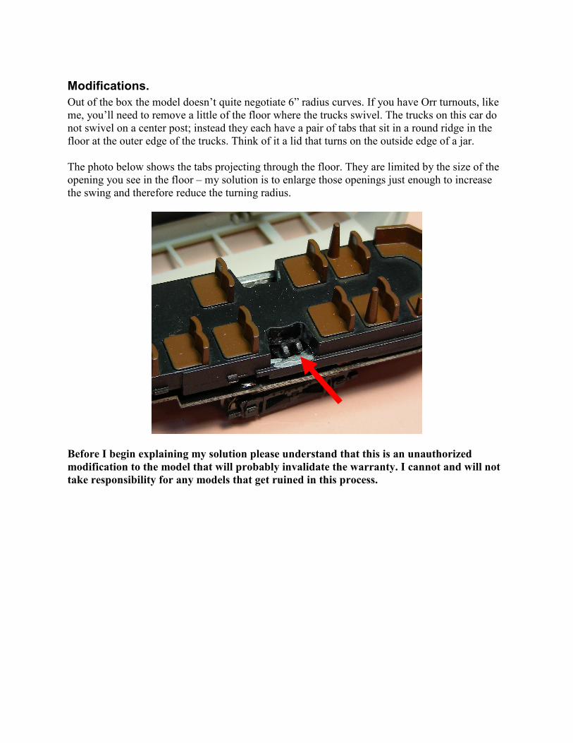
The photo below shows the tabs projecting through the floor. They are limited by the size of the
opening you see in the floor – my solution is to enlarge those openings just enough to increase
the swing and therefore reduce the turning radius.
Before I begin explaining my solution please understand that this is an unauthorized
modification to the model that will probably invalidate the warranty. I cannot and will not
take responsibility for any models that get ruined in this process.

Turning Radius:
The first step is to remove the trucks by gently pushing in and down on one tab while holding the
frame securely. The truck will drop out.
I removed some of the floor by first filing away a little of the edge that stops the truck tabs. Just
file up through the holes at the end of the curve of the hole. Caution – be sure the motor is
protected from filings or the car will grind to a halt on the first test run. See the photo below.
Once all eight edges are filed use a Dremel motor tool with a cutting bit as shown in the photo
below (the same bit as appears above). Get this bit down on the lower flat curved surface and cut
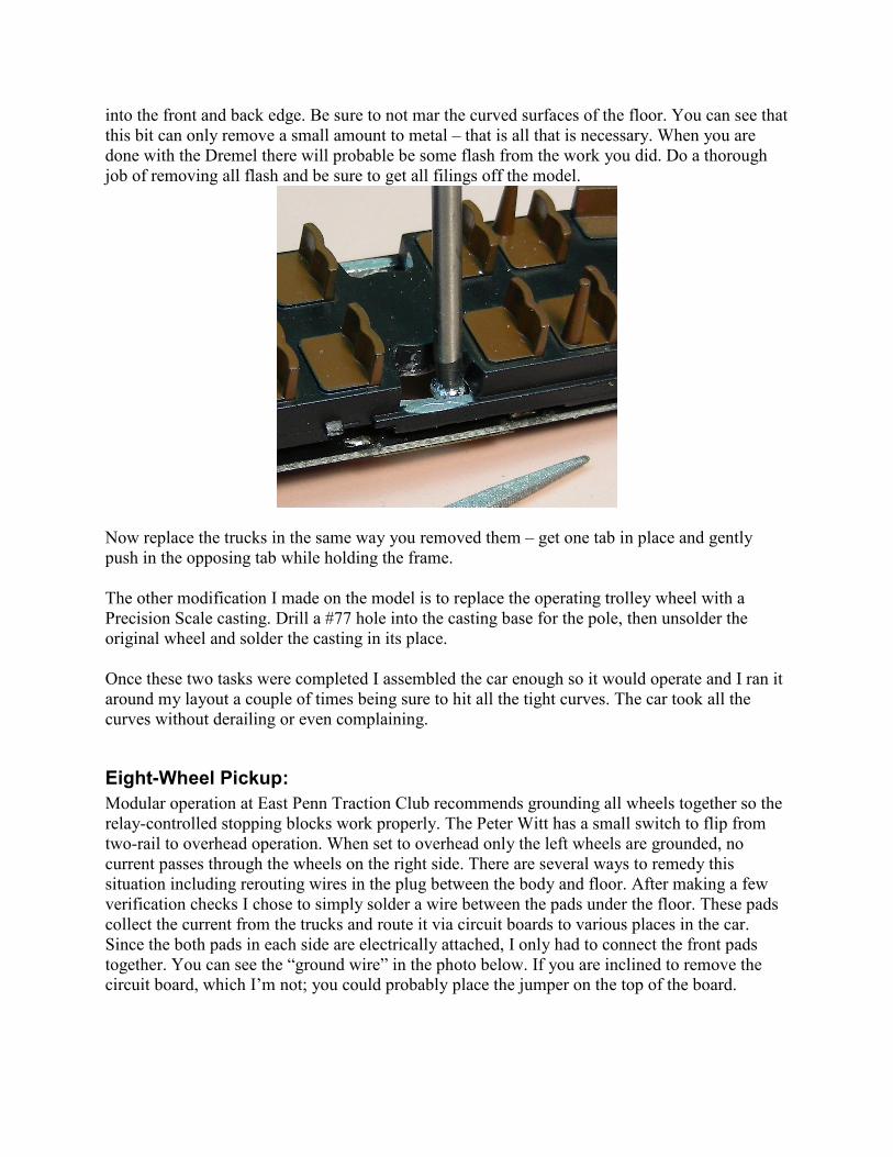
into the front and back edge. Be sure to not mar the curved surfaces of the floor. You can see that
this bit can only remove a small amount to metal – that is all that is necessary. When you are
done with the Dremel there will probable be some flash from the work you did. Do a thorough
job of removing all flash and be sure to get all filings off the model.
Now replace the trucks in the same way you removed them – get one tab in place and gently
push in the opposing tab while holding the frame.
The other modification I made on the model is to replace the operating trolley wheel with a
Precision Scale casting. Drill a #77 hole into the casting base for the pole, then unsolder the
original wheel and solder the casting in its place.
Once these two tasks were completed I assembled the car enough so it would operate and I ran it
around my layout a couple of times being sure to hit all the tight curves. The car took all the
curves without derailing or even complaining.
Eight-Wheel Pickup:
Modular operation at East Penn Traction Club recommends grounding all wheels together so the
relay-controlled stopping blocks work properly. The Peter Witt has a small switch to flip from
two-rail to overhead operation. When set to overhead only the left wheels are grounded, no
current passes through the wheels on the right side. There are several ways to remedy this
situation including rerouting wires in the plug between the body and floor. After making a few
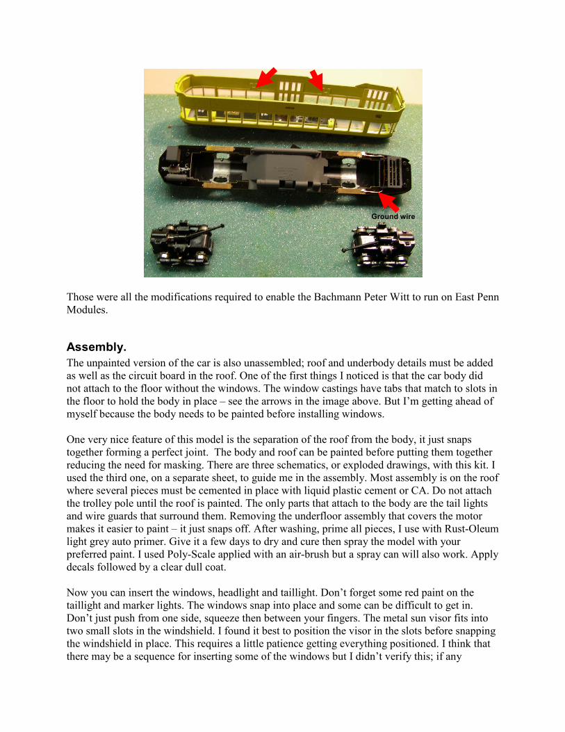
verification checks I chose to simply solder a wire between the pads under the floor. These pads
collect the current from the trucks and route it via circuit boards to various places in the car.
Since the both pads in each side are electrically attached, I only had to connect the front pads
together. You can see the “ground wire” in the photo below. If you are inclined to remove the
circuit board, which I’m not; you could probably place the jumper on the top of the board.
Those were all the modifications required to enable the Bachmann Peter Witt to run on East Penn
Modules.
Assembly.
The unpainted version of the car is also unassembled; roof and underbody details must be added
as well as the circuit board in the roof. One of the first things I noticed is that the car body did
not attach to the floor without the windows. The window castings have tabs that match to slots in
the floor to hold the body in place – see the arrows in the image above. But I’m getting ahead of
myself because the body needs to be painted before installing windows.
One very nice feature of this model is the separation of the roof from the body, it just snaps
together forming a perfect joint. The body and roof can be painted before putting them together
reducing the need for masking. There are three schematics, or exploded drawings, with this kit. I
used the third one, on a separate sheet, to guide me in the assembly. Most assembly is on the roof
where several pieces must be cemented in place with liquid plastic cement or CA. Do not attach
the trolley pole until the roof is painted. The only parts that attach to the body are the tail lights
and wire guards that surround them. Removing the underfloor assembly that covers the motor
makes it easier to paint – it just snaps off. After washing, prime all pieces, I use with Rust-Oleum
light grey auto primer. Give it a few days to dry and cure then spray the model with your
preferred paint. I used Poly-Scale applied with an air-brush but a spray can will also work. Apply
decals followed by a clear dull coat.
Now you can insert the windows, headlight and taillight. Don’t forget some red paint on the
taillight and marker lights. The windows snap into place and some can be difficult to get in.
Don’t just push from one side, squeeze then between your fingers. The metal sun visor fits into
two small slots in the windshield. I found it best to position the visor in the slots before snapping
the windshield in place. This requires a little patience getting everything positioned. I think that
there may be a sequence for inserting some of the windows but I didn’t verify this; if any
Ground wire
window appears to be blocked by a neighbor remove or loosen the neighbor. I had one window
near the back that would not stay in place. I cemented it but all others are just snapped into place
with no cement.
As is evident in the drawings, the circuit board screws to the top of the body. The trolley pole is
attached with a silver color screw and a plastic washer to keep it from pulling through the roof.
Once all these are in place, snap the roof onto the body. Snap the under body piece back in place
– the tabs are at different heights on either side so you can’t get in on backwards. The other
underbody pieces get cemented in place with CA. All that is left is to insert the electrical plug
and snap the body over the floor. Now you’re ready to run.
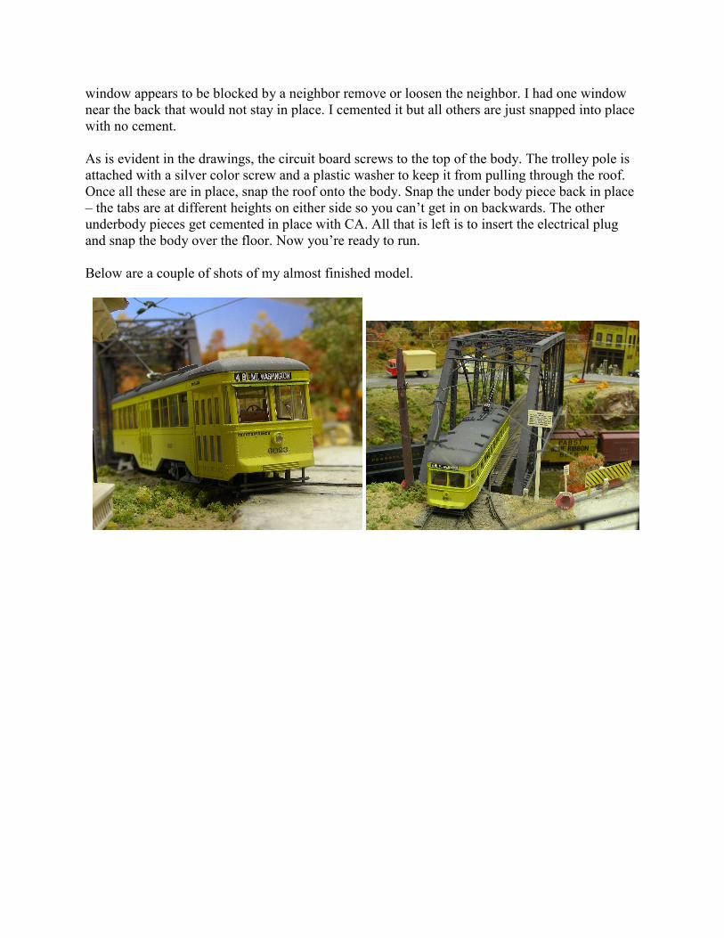
Below are a couple of shots of my almost finished model.