Embed Size (px)
Citation preview

May 2007
ISSUE 4
CONSTRUCTION OF THE WeCoHe PANTHER AUSFÜHRUNG G PART 1
Background
After years of waiting, a 1/16 Panther has not only arrived, but arrived by two separate manufacturers, furthermore, each is the base kit of the same vehicle which is a later production Ausführung G (version/type or model G). There’s a separate story behind the reasoning for this, but for a different time. The Ausf. G was developed mainly to correct some of the short-comings of the Ausf. A, the big difference was in the shape of the upper hull which facilitated producing them more rapidly as well as changing some of the thicknesses in the hull. Unlike what both of the manufacturers provided (a Panther produced in the late fall of 1944), my intention is to back-date it to one that was produced in the early summer of 1944. There were basically 3 manufacturers producing the Panther, and another one that assembled them for a short time. These manufacturers; Daimler-Benz, MNH, MAN, and Henschel & Sohn all had differences, and I’ve settled on one produced by MAN. The vehicle will have the typical zimmerit pattern produced by MAN as well as converting to the standard production mantlet. The production mantlet was supplied along with the ‘chin’-mantlet to the end of the war. It was a good decision by both WeCoHe and Tamiya in choosing to produce the Panther Ausf. G vice an earlier version is that it will be a piece of cake to convert a second Panther to another much desired AFV, the Jagdpanther. WeCoHe has been in the works producing this kit for almost two years. They wound up needing to issue it early, as Tamiya dropped the bomb and issued theirs. For now, you receive from WeCoHe almost all of the kit, as a few of the parts are still being produced, but should arrive soon. What you don’t get yet are a complete set of instructions, but WeCoHe hasn’t left it’s buyers in a lurch totally, as they’ve provided the instructions that have been produced thus far which are of the lower hull and a guide on how to make each angle on the armor plates that require beveling. Additionally, they’ve provided some CAD drawings for the questionable areas.
I will say having seen both of the kits from WeCoHe and Tamiya, the Tamiya is lacking in detail even by Tamiya’s standards, but with some work can be upgraded, especially utilizing the detail sets from WeCoHe. Unlike Tamiya’s previous 1/16 AFV, the Panther is essentially a repackaged Tiger I/ King Tiger, and like them, no PE sets, etc. The tank has no casting texture, no commander, or the MG. The WeCoHe Panther utilizes some stuff from the Tamiya Tiger I in its build, such as all the electronics, rubber tires, and swing arms. Within about 6-8 months, I assume there’ll be a rainstorm of after-market items for the Panther, including a slew of conversion kits.
1

What you receive with the WeCoHe kit now is pretty much what is seen in the photo, plus some of the new photo-etch pieces. Some things have yet to be developed or delivered such as the fenders or the muzzle brake, but I’m told they’ll be coming soon. The photos below were provided by Willy Loewer, and more photos can be seen at his website link at the bottom of the page. Lastly, this kit is not a kit-assemblers paradise that can be put together and painted over a weekend. Advanced modeling skills are definitely necessary to tackle this one (the sub guys are probably laughing as this is usually more than what they regularly get). Hopefully, the series of articles being written can alleviate some of these headaches and deliver a much superior and rugged product. The pieces are there, it’s just a matter of figuring the puzzle out. Time to bake the cake.
A picture of most of my Panther as Willy Loewer at CustomRCmodels received it, and is most of what is provided by WeCoHe. The amount of metal makes for one heavy running
vehicle. It will need some additional beefing up of the chassis, drive train, and running gear, but definitely won’t be a 3-5 pound running, bouncing toy.
2

Notice that the hull pieces were produced by CNC which means most of the angles will have to have a bevel sanded on them prior to assembly. Notice the ‘chin’ mantlet at the lower right, this will have to have the squared off portion removed in order to make the earlier production mantlet. Not a problem.
Sanding Angles The first order of business with this kit is to get the various angles sanded down to their proper angle, in order that the upper hull pieces can be assembled. This isn’t a hard task, but it’s one that close attention must be paid or you’ll wind up learning how to use fillers correcting them. With earlier kits from this manufacturer, not much was provided to aid the builder, it was pretty much, ‘here ya go, figure it out’. This time around they provided a set of ‘pre-instructions’ that makes the process much easier by providing angles and distance for each hull edge that will need to be sanded. Below is an example of one of the CAD drawings from the instruction showing the base angles and measurements:
3

This is a CAD drawing of the Panther’s upper glacis provided by WeCoHe showing two of the angles to be cut. Provided are the angle and the distance from the edge measurements.
‘Oder’ translates to ‘or’. The process of sanding angles is fairly simple, especially when given two parameters (angle and distance). Some individuals aren’t comfortable with this hurdle, so hopefully this all will help out. Below are some of the tools that helped me. The tools not in that photo are the sanding blocks and steel angle maker. Throughout the sanding process I used wet/dry 220 grit and sanded dry the whole time. Shown are the processes in sequence, sometimes being conducted on different pieces, but the process is the same.
4

Above are seen from the top, the bottom side of the upper deck with a measurement of 1.73mm drawn on the inside of the lower edge, digital vernier caliper, permanent marker, metal scriber, steel ruler, and off to the right the angle guide provided by WeCoHe.
First step is to determine which side the angle is going to be sanded on. If necessary, mock
up the pieces (they won’t perfectly fit of course, but you’ll be able to see the angle to be
5

made). Then with the vernier caliper set to the required measurement, scratch in a line following the edge of the piece. It only has to be deep enough to see.
Next, take the steel ruler and metal scribe and cut the line previously made by the vernier
caliper deeper.
As this is getting long in tooth, and people on dial-up will start sending me mail bombs, I’m dividing this one up into two parts.
Jake ACE member
Virginia Beach, Virginia www.tankace.org
www.customrcmodels.com
6

May 2007
ISSUE 5
CONSTRUCTION OF THE WeCoHe PANTHER AUSFÜHRUNG G PART 2
(This is continued on from Part 1 with sanding the hull armor plate angles.)
For me, the white plastic under lamplight made it difficult to see the surface being sanded,
so to correct this I marked not only the line cut (above), but the opposite edge that you don’t want disturbed (below).
1

Not shown in this photo is the angle maker. I set the angle maker to the desired angle, visually related that angle to the edge and piece, and started sanding. It’s far easier using a larger block when doing these angles, as they won’t waiver as much as a smaller sanding
2

tool. Now the process is sand a bit, check the angle made, adjust as necessary, sand some more, then check the angle made. Sometimes, you will be applying pressure more at one end than the other, and you will be able to see this as you’ve drawn the parameters, so apply some pressure where you weren’t previously and continue on. The big picture is to sand only as much to get on the right angle and get it near, but still proud of the marks. The fine tune is afterward.
Here the angle being made is about ¾ complete, and the angle is too shallow. In order to
help see it on the white plastic I color the offending area, increase the angle of the sanding block then sand some more. What you will end up with is plastic STILL remaining slightly
proud of the marks on either side.
3

Here’s a picture of the metal angle maker with an angle of 60° selected. To tune-in the
final angle on the plastic, you can drag the angle maker along the angle made and it will remove the high spots. On the leading edge of the angle maker you can see the desired
plastic being removed and leaving an incredibly tight and accurate edge.
4

Sanding gets really tedious at times, so to alleviate the process, it’s good to periodically switch to something else. Here I’m paralleling the sanding with constructing the gun
mechanism. This thing is pretty hardcore, and I’m sure the turret around it will break before it does. This is much in contrast to the other manufacturer’s delicate mechanisms.
There are many techniques to conduct the sanding process, and you will find your own, this particular one worked for me. These angles are all near completion, but I’d like to get the lower hull done to a point where I can use the additional interfaces from it in order to assemble the upper hull.
Jake
ACE member Virginia Beach, Virginia
www.tankace.orgwww.customrcmodels.com
5

June 2007
ISSUE 6 CONSTRUCTION OF THE WeCoHe PANTHER AUSFÜRUNG G -PART 3
Assembling the Sanded Panels Now that all of the armor panels have been sanded, it’s time to start putting them together. Unlike a conventional kit where you can build complete sub-assemblies then move to the next sub-assemblies within established parameters (the hull is already built and provides the guidelines), the work on this project does not allow for that, as you are establishing the parameters, and each is dependent on the other. Fail one, and it winds up being a compound problem, as other pieces will be out of alignment, which will put other pieces out…and so on. This is hands down the most difficult part of constructing this model. To throw gas further on the fire, the first guide-set of angles that were provided had some angles that were wrong, and more that you had to figure out from which aspect the angle was based on. Luckily, I figured them all but a couple, which will require some M1-A1 sanding, elbow grease, and some filler to correct, but not a big deal. The first set of instructions has been issued and now has all the correct information and it’s very nicely done, well thought and laid out, especially for a model of this scope. Before talking about joinery, here’s a tool I acquired about half-way through sanding the angles from Germany via Herr Loewer at CustomRCModels. It’s an anreißnadel which basically means ‘scribing-caliper’, and they’re not too expensive. I was using my digital vernier caliper for marking before, but that’s a bad practice for a measuring tool. You dial in the corresponding setting, place the tool at the required distance with the roller at a right-angle to the surface and scribe away. Very handy.
1

Comparing size: The vernier caliper and scribing caliper
Using the scribing caliper to mark the inside of the forward glacis to denote
the area to be sanded.
2

The upper hull requires the utmost attention to detail during assembly, more so than any other aspect of this model. In the photo below, brass tubing has been temporarily glued to the underside of the upper hull deck in order to keep the deck as flat as possible while pieces are attached to it. After this is done a proof fitment of the pieces to be assembled is done in order to limit last second surprises when the liquid glue brush is positioned ready to go.
The bottom of the upper hull deck with brass tubing positioned to keep bending of the deck
at a minimum.
Proof-fitment of the pieces to be assembled, noting any problem issues.
3

After any problems that revealed themselves during the proof-fitment are identified and corrected, it’s time to start gluing. To aid this process, I made some angles from .80” styrene, and spot-glued those at the nexus of the two angles while some serious gluing goes on between each joint. Note that only the sides are being glued to the deck, one at a time, the front glacis for now is only providing temporary support.
Here temporary angles are positioned while the side hull pieces are being glued.
Use liquid cement for gluing. What kind is not very important, just as long as it makes a
cohesive bond between the two pieces. I have about 3-5 different kinds and use whichever my hand picks up first. The liquid glue will capillary along the joint and you must be careful as the glue excess will run out the bottom and ruin the detail of the upper deck in no time. Do it in stages. Unless the model is going to be a shelf-queen and only be on display, you’re going to need to increase the strength of the joint. In the photo below you can see a method for doing this. Taking a strip of styrene whose surfaces roughly correspond to the surfaces to be mated to, glue it in place, then go over the whole joint with liquid glue, again being careful the glue excess doesn’t run out between the cracks. This fillet piece will melt, and applying slight pressure along the pieces length, push the piece into any gap below it. The glue evaporates pretty quickly so keep applying it as needed to work the piece at the joint. When done, what’s left is a vastly strengthened joint that will endure a lot of abuse.
This is a good time to basically talk about cohesive and adhesive bonds, glues, and their applications. I’ve had this topic surgically implanted by Dave Merriman enough times to where I can recite it backwards. The big picture is you want the strongest bond attainable for the particular piece to be glued. Each has advantages, disadvantages, and their applications. A cohesive takes two pieces and joins them into one piece, by basically melting the surfaces of the two pieces together. An adhesive just sticks one part to the other, the glue vice the parts being the bond. We’ve talked about using a glue to make a cohesive joint, but sometimes either it’s not
4

possible, or you’d destroy the piece, so you need an adhesive. You use an adhesive for things like gluing dissimilar materials, or with delicate parts. People do a lot with CA, and a lot of times it’s good. An example of what not to do is use CA to join the structure pieces, or better yet, CA with baking soda. A very fast assembled joint, but if you drop it, the bond shatters like glass. Not a good thing to have happen. Enough of all that. Anyway, you want a solid structure before you apply what gets put on it later, and mine’s going to receive: auto-body filler; Squadron putty; lacquer primer, various model oil paints; weathering washes and weathering what-not, and the last thing you absolutely don’t want to happen is for a crack at a joint to develop. Make it right the first go around.
Here a fillet is being glued into the awaiting joint.
After the sides are glued to the upper hull, the next order of business is to glue the front
glacis to the upper deck and hull sides. Again you’ll want to proof-fit and work out the problems, but some additional parameters are needed which will require some work on the lower hull. The lower hull is going to get some additional aluminum pieces that aren’t ready yet, so it can only be temporarily mocked up with the exception of the two side plastic panniers. These have been glued to their side panels and positioned at 90° to the hull. On the underside of these panniers, brass strips have been temporarily glued into place. The purpose of these is that the sides of the upper hull will set on them and keep the hull at the required height. The rear glacis is temporarily installed to give the exact position (forward and aft) of the upper deck, so the front glacis can be installed. All of these temporarily glued alignment items leave a good deal of glue residue on the structure. It’s not a big deal as they will wet sand out, but you want to do yourself a favor and don’t glue them onto a detailed portion that you’ll have to correct afterward. Keep to the flat smooth surfaces.
5

The temporarily assembled lower hull with brass mounting strips installed.
Now the forward glacis is installed and glued into place. At first it is temporarily glued, then turned over when dry, then additional strengthening from the underside is accomplished. Note also that I’ve used blue 3-M painter’s tape to further temporarily bind the structure while gluing is going on.
The forward glacis is now joined to the rest of the upper hull.
6

All the upper hull pieces are now joined. Strange how even on a 6 ½’ work table, I still only
get about 2’ of work-space.
Now that the upper hull is done, next will be filling, sanding, and further strengthening and aligning of the structure. I’m really having a blast building this WeCoHe Panther, not as much as the Nautilus, but still a blast.
Jake
ACE member Virginia Beach, Virginia
www.tankace.orgwww.customrcmodels.com
7

July 2007
ISSUE 7 CONSTRUCTION OF THE WeCoHe PANTHER AUSFÜRUNG G -PART 4
Metal Work-Pickling and Strengthening Part 4 continues with work on the upper and lower hulls of the tank. When working outside of the original scope of work, especially when the work demands continuous assessment/ reassessments of the design, it’s good to mock up the pieces that will come into play, in order to reveal problems BEFORE they are built. Below the Panther is mocked up while checking both hull and turret interfaces. Doing this revealed some issues that will need to be addressed in both areas. Mocking up pieces is a continual process, and should be done at each major juncture of the build.
The mocked-up Panther Ausf. G
Before starting the builds on our Panthers, both Willy Loewer and I went over what areas we wanted to improve. Willy’s a hardcore RC guy who builds for outright sheer terror in both strength and durability, and I’m a detail freak, so we have continuously been throwing and taking ideas out of the pot to make this as near a one-time build as possible. I can also add that Daryl Turner has provided his own spice bag into the pot and has inspired some of the directions of the build areas also. After getting the basic lower hull assembled it is time to add an 1/8”
1

strengthening plate to the bottom. I’ve cut this plate so that it will not be seen unless you turn it over and will incorporate both the screw mounting holes of the hull stays, and the twin gearbox sets. The width is even with the hull plastic but not to interfere with the swing arms. The forward and aft ends were beveled on a mill, and the screw holes countersunk to receive flathead screws that will seat slightly below the face of the plate. The bottom strengthening plate will dramatically decrease the twisting of the hull, as well as provide a more substantial mounting base for components.
Bottom strengthening plate after it has been cut, angles beveled, and
mounting holes drilled and countersunk.
These flathead screws required a countersink with angles of 90°. My toolbox had two
countersinks and neither was a 90°, so I had to get yet another.
2

Prior to mounting the strengthening plate, I felt this was a good time to pickle the plethora of metal that is being involved. Just with the hull, and not counting the stainless steel screws there are eight different types of metal. If not familiar with a particular metal, it’s good to test a small portion before applying acid on it. Such metals as zinc and white metal react quickly, and may even need the zinc chloride acid watered down to a degree for pickling. Other metals take much longer like aluminum and steel. The reason for pickling is to microscopically prepare the surface for painting. Primering is not enough. If you’ve run RC vehicles over the ground you’ve seen how fast the primer and paint come off of an unprepared surface. Now real-deal Brian Stark, the resident guru of car surface preparation/restoration says he uses a metal primer that has a metal etchant that’s integral in the primer. Brian makes his living off this stuff, so I consider it gospel, but as I recall the stuff cost a ba-zillion dollars, I’ll check sometime. For now, we’re doing it the old school way, so haul out your rubber gloves. The product I use is the photo-etch solution (primarily zinc chloride) that you get from Radio Shack for about $5 which will last a long time. Additionally, photo-etched metal has already gone through the process, so doesn’t need additional pickling.
The overall process is basically put some solution on the metal with a rag (for broad areas) or acid brush (for small areas), work the solution until the solution starts to darken, then you must halt the pickling process by neutralizing the acid. I always have a big bowl, or bucket full of water with a lot of baking soda dissolved in it. When you put the item in the neutralizing solution, keep working the areas over with a separate rag or brush, as the acid sometimes creates a layer that simple immersion may not get to. Just keep rubbing the surface until confident that you’ve addressed it all. One last thing, do this on a surface you don’t care jack about, and move everything else to the side. Accidents do happen.
In this photo, seven different metals are shown to be pickled. The swing arm (made of zinc) and the lower drive housing guard (made of white metal) seen mounted on the forward end
of the hull were immersed for 1-2 seconds.
3

This is the first time I’ve pickled nickel-silver, so I tried a small piece, noting no issues, and commenced on the lower drive housing on the left. Seen un-pickled is the bow machine gun
housing on the right. Immersion time was about 10 seconds.
The metal pan, stays, and strengthening plate took the longest to pickle. The broad plate
and pan were done with a soaked rag, and the long stays were done with an acid brush, all the time working the acid over the surfaces.
4

Here is the strengthening plate after pickling and being mounted to the lower hull.
Jake
ACE member Virginia Beach, Virginia
www.tankace.orgwww.customrcmodels.com
5

July 2007
ISSUE 8 CONSTRUCTION OF THE WeCoHe PANTHER AUSFÜRUNG G -PART 5
Application of Rare Earth Magnets A while back Brian Stark had told me about using rare earth magnets and described some of these applications, but it was late that I threw it into the back of my mind and filed under ‘other’. About a month later Dave Merriman showed me how he replaced dogbones on the drive shafts on one of his subs. I was shocked of how much strength the little magnets had in that application and immediately thought, ‘I got to get me some of these!” These magnets come in a variety of shapes, sizes, and coatings. A hidden benefit of getting a bag of these, is that if anyone that comes into your shop demanding attention from the little time you have to spend modeling, just hand them the bag, and they’ll forget all about what they came in their for. I ordered about $15 worth and got about 60 different magnets. In the photo below are a few of the variety I ordered with a variety of coatings available on them, even plastic.
Some of the varieties and shapes of the rare earth magnets.
1

My intention with the magnets in this vehicle is to facilitate the means of access, while keeping the hull tight at the same time. Because this is a radio controlled vehicle, installing magnets can be a recipe for a headache if not done correctly due to possible signal interference. I placed the magnets within pieces of Renshape-40 foam, machining out hole in the bottom’s center, and epoxied them in. The pieces of foam were shaped to fit inside the aft end of the tank’s panniers and conformed to the inside of the side hull plates with a 60° angle.
Magnets installed inside the high-density foam
I want the back end of this tank to be tight and not wobble or unseat. If it does it may destroy some of the filling and zimmerit work that is being done. I epoxied two pieces of tin on the back inside portions of the pannier. Then placed the foam pieces with the magnets installed on them and placed them on the tin pieces without gluing them.
2

Plates installed on top of the panniers towards the Panther’s rear.
The foam fitted in place flush against both the hull side and seated on the tin plate.
3

Once in place, and also ensuring that all of the pieces and parts that are yet to be installed will also not be interfered with the foam mountings, a number of rubber bands are wrapped around the hull to ensure a tight fit and then the foam pieces are permanently glued with epoxy to the inner sides of the hull. Not taken lightly, there’s a lot to contend with installing these pieces where they are. Some things didn’t work out. The foam was actually the third design I drafted up.
Foam pieces glued to the inner sides of the hull. The foam needed to not only connect the two hulls together, but they had to fit between all the items that go into this hull. Some are
apparent, some not. It’s a good idea to mock up the items or draw them out.
From the rear you can see how the not only how the magnet will lock the two halves of the hull together, but the foam will also provide additional supporting strength for the upper
deck.
4

Taking a break away from the work on the hull, the turret I’ve been doing off an on in stages when I take a break from hull work which I’m primarily focused on. Since the styrene was CNC-cut and the pieces have right angles, the base of the turret was also in this condition, and since the turret is angled, the plate requires that the inside angles be cut in order to fit the piece within the turret. Following this, 3mm pan screws were installed initially for alignment, and then removed one by one while the holes were countersunk and flat head screws installed. When countersinking here, I made sure that the results left the heads of the screws well submerged below the surface of the lower plate. The turret has a lot of weight to it that will hamper proper operation of the traverse mechanism as-is. I’m looking at using opposing sheets of Acetal to assist in decreasing drag.
The inside rim of the lower plate has been cut to conform to the inner turret sides, and the
screws are being installed.
5

Screws heads installed below the surface of the plate.
Jake
ACE member Virginia Beach, Virginia
www.tankace.org www.customrcmodels.com
6

July 2007
ISSUE 9 CONSTRUCTION OF THE WeCoHe PANTHER AUSFÜHRUNG G -PART 6 In the last few articles we’ve been concentrating on getting the hull pieces made and fitted together. Now it’s time to start cleaning up the joints and interfaces that are left behind when joining to increase both strength and visual integrity of the model. In the photograph below is the ‘murderer’s row’ lineup of fillers and finishing products for body work. These are all auto-body products, and you have basically three levels of filling and finishing prior to primering; on the lower right in the big can is ‘Z-Grip’, it is used for filling in large areas; The tub on top and the dark blue can are glazing putties, and basically you can use one or the other. These can be used alone for light areas, or used on top of the ‘Z-Grip’ filler; in the yellow tube is ‘Nitro-Stan’, and this stuff will definitely clear any and everyone out of your shop that’s not used to it. This stuff is used for cleaning up the fine scratches and can be applied with finger or acid brush. All the products here are two-part, except for the Nitro-Stan, they have a hardener (the tubes seen on the mixing pad). You basically mix up small portions that are needed, and you have a couple minutes working time. If you use more hardener, the stuff will set up fast. The hardener comes in two colors, blue and red, and it’s good to get both, as you can show distinction between layers or areas. The build process can move very fast with this stuff, and you can even make parts out of it, or use it to texture with among other things. The car auto-body guys use large quantities of this stuff at a time. They can’t fool around waiting for something to dry and harden when a customer’s waiting and they’ve got a lot full of cars. I use Squadron Putty pretty much for only one thing now, and that’s zimmerit on styrene, it’s not very good as a filler, as it shrinks too much. Also, do yourself a favor and buy the Evercoat brand, don’t buy the cheap Bondo, as it’s just crap in more ways than I can describe.
Implements of Body Work
1

In the two photos below you see a lot of blue tape. This is 3M brand painter’s tape that you can get from Home Depot or Lowe’s. It’s low-tac and you can even make it lower by sticking it on and off of your clothes a few times before putting it on. You’d do this when painting a few different colored layers or like what I often use it for, painting different colored numerals. Here I’m using it to mask areas I don’t want the glazing putty to go on. Some tape I’ve already removed such as between the side armor plate and the upper deck. Areas that provide little purchase area such as the long groove on the side need to be prepared further by scribing the groove between the joints deeper and hacking the area up slightly with a scribing tool. Place the filler on top, let it dry, and with wet/dry sandpaper (#220) sand each to the angle it’s on and you’re left with a clean angled joint. The rear plate of the tank had been permanently joined to the tank, and it is being finished here as well as all the upper hull joints. The Panther is going to represent one produced in the Spring of ’44, it will have zimmerit, so the flame cut joints on the hull I don’t have to represent.
Applying Automotive Glazing Putty
You want to apply this stuff adequately proud of the joint, it will wet sand down easily
2

Below after wet sanding you can see how the joints cleaned up. After applying primer you won’t be able to tell where the plastic starts and the putty begins. Add to this that these areas will have zimmerit as well. At the top between the side and front armor plates, the glazing putty did not fill as well. This area needs to be scribed out, that is it is hatched up slightly before another coat of glazing putty is applied and wet-sanded.
After wet sanding, clean joints are left. The area on the upper left will have to be slightly cleaned out and
an additional coat applied, then wet sanded.
Interface between the panniers and the rear plate cleaned up nicely. This area also was scribed down
prior to applying putty as it’s a thin area and prone to chipping. The scribing provides additional ‘tooth’ for strength.
3

This is what we’re left with. All the upper hull joints filled and finished.
The next two photos show the mounting screws for the forward and aft mounting plates being glazed over.
These screws were countersunk below the surface of the armor. The edges of the holes were hatched up also with a scriber as it’s a shallow amount of glazing putty, and after the putty has dried, the areas were wet sanded.
The aft plate and front lower glacis armor mounting screws puttied over.
Often you get tired of working on one particular area of a subject, especially if it’s lengthy, so you
switch to something else that needs accomplishing. In the photo below the radiator air cooling induction grates are being cleaned up of flashing and casting seams for trial fitment. These pieces will also partake of an acid bath prior to installation. Lot’s of metal on this kit.
4

Cleaning up the radiator air cooling induction grates.
Jake
ACE member Virginia Beach, Virginia
www.tankace.org www.customrcmodels.com
5

August 2007
ISSUE 10 CONSTRUCTION OF THE WeCoHe PANTHER AUSFÜHRUNG G -PART 7 Continuing with the work presented in Panther Part 6, work now moves into tightening up the joints between the upper and lower hulls, as well as creating a seating ‘lip’ inside the upper panniers. The materials utilized are the same as before with the addition of using some wax paper. Wax is used to provide a barrier, so that the new material, in this case filler or glazing putty won’t stick to it while it is being constructed on the opposite surface. Very tight joints can be created here. I had a choice to use either wax paper or wax out of the can, and my choice for wax is bowling alley wax as it spreads and stays well. Either method provides the same results and has its own inherent advantages. Bowling alley wax will conform to a non-consistent surface, whereas wax paper is better when the surface is relatively smooth and you don’t have to clean it off afterwards. In the photo below you can see a sheet of wax paper in the foreground and a sheet of wax paper wrapped over the pannier edges and taped down that will be protected as the filler or glazing putty is applied to the adjacent surface, in this case the upper hull.
Wax paper is wrapped over the panniers to seal them from the filler and glazing putty.
1

Before starting, as the styrene is very smooth, the desired areas that will receive the filler are scored with a sharp object to provide adequate ‘tooth’ for the filler to adhere to. The first application will be the tougher Z-Grip Filler. This is placed on the inside edges of the upper hull (which is facing
upward in the photo). The lower hull is then set down on top and pressed into the Z-Grip filler which a lot of the excess filler comes out on top. A putty knife then is dragged the entire length of the joint
pressing putty back into the joint (see the two photos below), all the while creating one surface between the pannier and the side hull’s bottom edge (now facing upward).
filler pressed into the joint and creating one single even surface between the two hulls.
The Port side also.
2

As there is only a thin layer at the separation point, it’s relatively easy to separate the two hulls. After separating the two hulls, remove the wax paper; place the two hulls back together and wet sand the excess off using wet/dry 220. Inspect the areas, mark the areas that didn’t come out correctly, and with a sharp tool hatchet up the area to provide ‘tooth’, put wax paper back on, wait till the surfaces are adequately dry, then conduct the same procedure again. Sometimes it takes a few times to correct all the problem areas. No big deal. In the photo below you can see the seating lip made from the filler. When completed and everything has been sanded smooth, and the surface is dry. Take some thin CA and apply it to all of the surfaces with the filler on it. The stuff is porous and the CA will give the filler increased strength. Afterwards, wet sand with some 1000 grit and that’s it.
Filler has created a seating lip for the panniers in the upper hull.
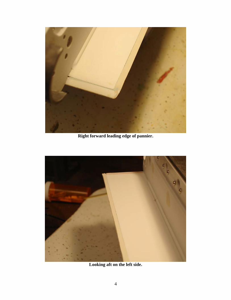
The two photos below show how close you can get these working edges when utilizing this method. The result will be a vehicle that will have a further reduction of dust within the hull, as well as having a
more correct appearance.
3
Right forward leading edge of pannier.
Looking aft on the left side.
4

Another side job going on is installing the ga-zillion micro-bolts in each wheel. There are total of 16 road wheels, and on each road wheel there are 24 bolts on the outer rim, 8 that surround the inner hub, and 8 that are on the hub cover itself, all for a grand total of 640 bolts. The bolts on the outer rim are extremely tiny, but not the tiniest in the kit by far. Still pretty small, so I place all the tools along
with a magnifying glass inside a box lid, as sometimes the bolt heads invariably pop out of the tweezers. I cut a deep slit in a piece of styrene and filled it with CA. I dip the threaded portion into the CA then install them on the wheel. Later I’ll take a toothpick and dipping that into the CA, I’ll place a little more glue at the bolt head surface, ensuring it’s firmly glued down. Once complete, each wheel
will be pickled, primered, base-coated, and the tires installed.
The 24 outer bolts are being installed, 8 larger ones will go in the inside 8,
and 8 more on the hub cover
5

The set up for installing the micro-bolts.
Once complete with installing the initial 32 bolts per wheel, a shaft is installed into each, but it’s a tight
fit, and needs to be wetsanded to fit. I used some 1000 grit sandpaper, and put the shaft in a Dremel tool and after soaking the sandpaper, made short work of polishing down the shaft. After words, the
rest of the hardware was installed on the wheel with the exception of the wheel hub covers. These will be installed at a later date.
Polishing each wheel shaft to fit.
6

The Panther is going to be displayed at an upcoming show in its present condition. As we want to display it showing off the metal, the running gear is fully assembled. Following the show, it will again
be disassembled so the wheels can be pickled, primered, and painted, and the interior of the tank painted out. Additionally, pre-assembling areas of construction reveal faults either in design, or
changes that were made by the builder, or things that can be done to enhance performance. All three areas revealed something that needed addressing, so no time was lost.
Amazing how much larger a tank is when the running gear is installed. A lot of the fittings have
already been worked, but will be added later when details of the hull are completed. Jake
ACE member Virginia Beach, Virginia
www.tankace.orgwww.customrcmodels.com
7

1
January 2009
ISSUE 12 CONSTRUCTION OF THE WeCoHe PANTHER AUSFÜHRUNG G -PART 8
Well finally with some time off I can re-commence on the pile of model projects that have been continuing to grow into the stratosphere. My first task jumping back into the Panther is to complete the 672 bolts that go into the wheel assemblies and finally call them complete (For a better look see Part 7). You have 26 bolt heads on each outer rim, then another 8 surrounding the wheel cap, and another 8 on the wheel cap. Multiply this by 16 wheels and it’s one hell of a lot. Each bolt also doesn’t fit into it’s hole, and you have to cut each shaft to length, and these suckers are micro small. Below you see two completed wheels and three wheel caps. The Wheel on the left is complete, whereas the one on the right still is awaiting it’s wheel cap and you can see the wheel axle and one of the retainers.
A lot of micro work here

2
Here’s a closer photo of the three wheel caps. The one on the left shows a completed outside face of a cap with it’s 8 bolts and 4 retainers. The middle cap shows the backside where each bolt shaft has gone through, but haven’t been ground down flush yet. The one on the right is a completed wheel cap that has been ground down smooth. Smoothing down the back is needed in order to properly mate the cap to the inside of the wheel.
Three views of the wheel cap
Below is a photo of all the assembled wheel sets. What will further be done to the wheels is to remove the tires, treat the metal with etching solution or just screw it and go with an etching automotive primer, and put on a base-coat of dunkelgelb (dark yellow). These are now set aside in a box, so I can get back to working on the lower hull.
Wheel sets finally complete

3
The next task is to replace the existing track pins provided by WeCoHe with some provided by Kenny Kong. The original pins are a much smaller diameter than the holes they are supposed to go into, resulting in the pins coming out each time you turn them over. My buddy Willy Loewer talk to Kenny about it and they came up with a correction, and even provided extra pins.
Changing out track pins with hammer and punch. Below you can see the difference in the pins. Below the brass punch you can see the original pin with a flat head. The replacement pin comes with an oval shaped head that is a larger diameter than the track hole. You insert the pin then using the hammer and punch you force into into the zinc track hole. This is a pretty tight connection, but I’ll still back it up with some CA to provide extra strength and filler. I’ll need to keep at least one pin removeable per track for track removal. I’ll mark this one with a red head and have it on the backside of the track.
Upper pin is the original pin getting replaced and the lower pin is the replacement.

4
Here’s how they are in the track. The pin on the left is fully inserted, the one in the middle is still awaiting to be punched, and the one on the right is the original pin. I can’t remember how many there are total, but it’s about 90+ per track. After this is completed, these tracks will get acid-etched to ‘dirty’ them up, then washed with some rusty black paint to hit the recesses, the I’ll take some light sand paper and go over all the contact areas of the track (faces, guide teeth, and outsides) to provide a more shiny appearance in those areas.
Left to right; new track pin fully inserted, new track pin awaiting the hammer and punch, and
old track pin.
Now I can get back to work on the lower hull which is about ready for doing weld seams and applying initial zimmerit. I’m also paralleling the work on the turret which is quite an assembly in it’s own right. Both have an incredible amount of photo-etched pieces that need to be applied. I’m still debating what the end-use of this vehicle is going to be. It will not be made into a battler, as an amount of detail will be lost, it will be either a full runner, or a shelf queen on a nice base. Still debating.
Jake
ACE member Virginia Beach, Virginia
www.tankace.org www.customrcmodels.com
http://forum.model-marina.com/