Embed Size (px)
Citation preview

8/4/2019 Balancing Control of Bicyrobo by Particle Swarm Optimization-based Structure-specifield Hoo Loop Shaping Control
http://slidepdf.com/reader/full/balancing-control-of-bicyrobo-by-particle-swarm-optimization-based-structure-specifield 1/22
1
Balancing control of Bicyrobo by particle swarm optimization-based
structure-specified H∞ loop shaping control
Bui Trung Thanh, Manukid Parnichkun*
School of Engineering and Technology, Asian Institute of Technology,
P.O. Box 4, Klong Luang, Pathumthani 12120, Thailand *
Corresponding author. Tel.: +66 2 524 5229; Fax: +66 2 524 5697
E-mail address: [email protected] , [email protected]
Abstract
In this paper, structure-specified H∞ loop shaping control using particle swarm optimization
(PSO) is proposed to control balancing of Bicyrobo, a bicycle robot with gyroscopic stabilizer.
The structure-specified H∞ loop shaping controller design normally generates a complex
optimization problem. PSO is an efficient optimization method used to solve multi-objectives and
non-convex optimizations. A model-based systematic procedure for designing particle swarm
optimization-based structure-specified H∞ loop shaping controller is presented in this paper. The
controller obtained from this method is simple in structure but still robust. The proposed control
algorithm is applied to balance the bicycle robot, which is unstable system involved with sources
of uncertainties due to un-modeled dynamics, parameter variations and external disturbances.
Simulation and experimental results show the robustness and efficiency of the controller in
compared with the proportional plus derivative (PD) controller, and the conventional H∞ loop
shaping controller.
Keywords: Bicycle robot; Structure-specified controller; H∞ loop shaping control; Particle swarmoptimization; Gyroscopic stabilizer.
1. Introduction
Electrical bicycle is a good mean of transportation because of its advantages on environmental
friendly, light weight, and capability of traveling in narrow roads. However, bicycle is unstable in
nature. Without a proper control, it will easily fall down. Hence, development of a self-balancing
bicycle is an interesting topic for many researchers. An exciting example of bicycle robots is
Murata Boy robot developed in Japan in 2005 [1]. There are many methods used to control
balancing of this system such as flywheel balancing by Beznos et al. in 1998 [2], Gallaspy in1999 [3], and Suprapto in 2006 [4], mass balancing by Lee and Ham in 2002 [5], and steering
balancing by Tanaka and Murakami in 2004 [6]. Among these methods, flywheel balancing
method which uses a spinning wheel as a gyroscopic stabilizer is a good choice because the
response time is short and the system can be stable even at stationary position. The balancing
principle using flywheel can also be applied to many other systems which require dynamics
balancing during movement, for example, balancing of a biped robot [7]. Various balancing
8/4/2019 Balancing Control of Bicyrobo by Particle Swarm Optimization-based Structure-specifield Hoo Loop Shaping Control
http://slidepdf.com/reader/full/balancing-control-of-bicyrobo-by-particle-swarm-optimization-based-structure-specifield 2/22
2
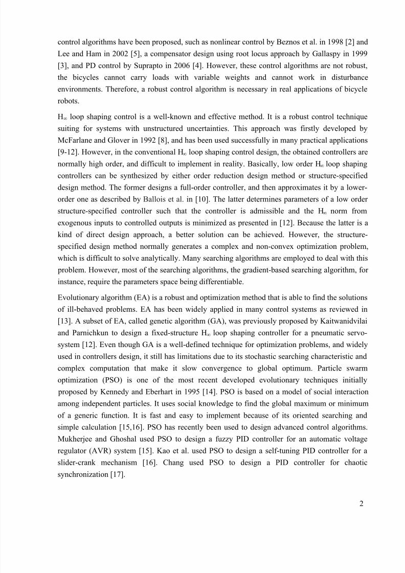
control algorithms have been proposed, such as nonlinear control by Beznos et al. in 1998 [2] and
Lee and Ham in 2002 [5], a compensator design using root locus approach by Gallaspy in 1999
[3], and PD control by Suprapto in 2006 [4]. However, these control algorithms are not robust,
the bicycles cannot carry loads with variable weights and cannot work in disturbance
environments. Therefore, a robust control algorithm is necessary in real applications of bicycle
robots.
H∞ loop shaping control is a well-known and effective method. It is a robust control technique
suiting for systems with unstructured uncertainties. This approach was firstly developed by
McFarlane and Glover in 1992 [8], and has been used successfully in many practical applications
[9-12]. However, in the conventional H∞ loop shaping control design, the obtained controllers are
normally high order, and difficult to implement in reality. Basically, low order H∞ loop shaping
controllers can be synthesized by either order reduction design method or structure-specified
design method. The former designs a full-order controller, and then approximates it by a lower-
order one as described by Ballois et al. in [10]. The latter determines parameters of a low order structure-specified controller such that the controller is admissible and the H∞ norm from
exogenous inputs to controlled outputs is minimized as presented in [12]. Because the latter is a
kind of direct design approach, a better solution can be achieved. However, the structure-
specified design method normally generates a complex and non-convex optimization problem,
which is difficult to solve analytically. Many searching algorithms are employed to deal with this
problem. However, most of the searching algorithms, the gradient-based searching algorithm, for
instance, require the parameters space being differentiable.
Evolutionary algorithm (EA) is a robust and optimization method that is able to find the solutionsof ill-behaved problems. EA has been widely applied in many control systems as reviewed in
[13]. A subset of EA, called genetic algorithm (GA), was previously proposed by Kaitwanidvilai
and Parnichkun to design a fixed-structure H∞ loop shaping controller for a pneumatic servo-
system [12]. Even though GA is a well-defined technique for optimization problems, and widely
used in controllers design, it still has limitations due to its stochastic searching characteristic and
complex computation that make it slow convergence to global optimum. Particle swarm
optimization (PSO) is one of the most recent developed evolutionary techniques initially
proposed by Kennedy and Eberhart in 1995 [14]. PSO is based on a model of social interaction
among independent particles. It uses social knowledge to find the global maximum or minimum
of a generic function. It is fast and easy to implement because of its oriented searching and
simple calculation [15,16]. PSO has recently been used to design advanced control algorithms.
Mukherjee and Ghoshal used PSO to design a fuzzy PID controller for an automatic voltage
regulator (AVR) system [15]. Kao et al. used PSO to design a self-tuning PID controller for a
slider-crank mechanism [16]. Chang used PSO to design a PID controller for chaotic
synchronization [17].

8/4/2019 Balancing Control of Bicyrobo by Particle Swarm Optimization-based Structure-specifield Hoo Loop Shaping Control
http://slidepdf.com/reader/full/balancing-control-of-bicyrobo-by-particle-swarm-optimization-based-structure-specifield 3/22
3
In this paper, PSO is used to search for parameters of a structure-specified H∞ loop shaping
controller. In the method, a nominal model of the system is firstly shaped by a pre-compensator
and a post-compensator to achieve a desired open loop shape. A structure-specified controller is
then defined. Finally, PSO is used to search for parameters of the controller so that the controller
is admissible and the H∞ norm from exogenous inputs to controlled outputs is minimized. The
proposed algorithm is practically applied to the balancing control of Bicyrobo, a bicycle robot
with gyroscopic stabilizer. By neglecting forces generated from moving forward and steering, a
simplified dynamics model of Bicyrobo is derived using Lagrange method. The un-modeled
dynamics, parameter variations, and external disturbances make the system complicate and
require a robust controller. The simulation and experimental results show robustness and
efficiency of the designed controllers in compared with the PD, and the conventional H∞ loop
shaping controllers.
The remainder of this paper is organized as follows. In Section 2, a prototype of Bicyrobo which
is used as a platform to test control algorithm is described. Section 3 explains a systematic procedure for designing the proposed controller. Simulation and experimental results are
presented in Section 4 and Section 5. Section 6 finally concludes the paper.
2. Configuration and dynamics model of Bicyrobo
2.1 Configuration of Bicyrobo
A bicycle robot, Bicyrobo, has been developed at Mechatronics Laboratory, Asian Institute of
Technology (AIT), as a platform to test performance of the proposed control algorithm. The
system is modified from a regular size bicycle. Fig. 1 shows a photograph of Bicyrobo. The robot
is designed so that it can carry loads, go forward, and turn left or right without falling down.
Fig. 1. Photograph of Bicyrobo
Bicyrobo is equipped with the following components: a flywheel with weight of 8.1kg and
diameter of 380mm for creating precession torque; a 48V-200W-3600rpm DC servo motor for
rotating the flywheel around its spinning axis; a 48V-200W-3600rpm DC servo motor with 5:1

8/4/2019 Balancing Control of Bicyrobo by Particle Swarm Optimization-based Structure-specifield Hoo Loop Shaping Control
http://slidepdf.com/reader/full/balancing-control-of-bicyrobo-by-particle-swarm-optimization-based-structure-specifield 4/22
4
chain transmission system for controlling the flywheel control axis; a 12V-15W-10rpm gear box
DC motor for steering Bicyrobo to turn left or right; a 12V-35 W-100rpm gear box DC motor for
driving Bicyrobo to move forward; a PCM-3350 embedded PC running at 300MHz as a central
controller with extended A/D and D/A boards; a VG400CC vertical-gyro sensor for measuring
the lean angle of Bicyrobo; an EB6-CWZ encoder for measuring angular position of the flywheel
control axis; and signal conditioning circuits. The dimension of Bicyrobo is about 1.65m in
length, 0.43m in width, and 1.14m in height. Its total weight is 51.2kg.
Fig. 2. Hardware configuration of balancing control system
The hardware configuration of the system is shown in Fig. 2. Program for implementing control
algorithms is written in C and run on PC/104 under DOS to ensure real time control.
2.2 Dynamics model of Bicyrobo
A complete dynamics model of a bicycle as derived by Sharp in 1971 [18] is complicated since
the system has many degrees of freedom, and not suitable for control purpose. Dynamics model
of a bicycle is basically based on equilibrium of gravity forces and centrifugal forces. In this
paper, a simplified dynamics model of the bicycle for balancing control purpose is derived using
Lagrange method by neglecting forces generated from moving forward and steering of the
bicycle. This model is based on the one proposed by Gallaspy in [3]. Several assumptions are
made to simplify the system as follows:
• The system is simplified to two rigid body links. The first link is the bicycle frame that has
one degree of freedom (DOF) on leaning angle only, rotation around Z axis. The second link
is the flywheel which has three DOFs including rotations around X1, Y1, and Z axes (Fig. 3).
• The flywheel is assumed to have constant speed ω. Center of gravity of the flywheel is fixed
relative to the bicycle frame.
The principle for balancing using flywheel is explained as follows: When the flywheel rotates
with a constant speed around Y1 axis, if we control angular position of the flywheel around X1

8/4/2019 Balancing Control of Bicyrobo by Particle Swarm Optimization-based Structure-specifield Hoo Loop Shaping Control
http://slidepdf.com/reader/full/balancing-control-of-bicyrobo-by-particle-swarm-optimization-based-structure-specifield 5/22
5
axis, angular momentum on Z1 axis will generate a torque. This torque is called precession torque
generated by gyroscopic effect, and it is used to keep Bicyrobo balance.
Fig. 3. Diagram of reference coordinates of Bicyrobo: (a) side view; (b) front view
Diagram of the simplified reference coordinates is shown in Fig. 3, where B and F denote bicycle
and flywheel centers of gravity, respectively. The lean angle of the bicycle around Z axis is
defined as θ , and the angular position of the control axis of the flywheel around X1 axis is defined
as φ. The angular velocity of the bicycle around Z axis is defined as θ & , and the angular velocity
of the flywheel around its control axis (X1 axis) is defined as ϕ & . Since the flywheel center of
gravity does not move related to the bicycle center of gravity, absolute velocities of B and F are
given by
b bv hθ =&
(1)
f f v hθ = & (2)
where hb, h f are the height of bicycle center of gravity, and the height of flywheel center of
gravity, respectively. To derive the dynamics model of the system, Lagrange equation in [19] is
used
i
i i i
d T T V Q
dt q q q
⎧ ⎫∂ ∂ ∂− + =⎨ ⎬
∂ ∂ ∂⎩ ⎭&(3)
where T is system total kinetic energy, V is system total potential energy, Qi is external forces,
and qi is generalized coordinate. V and T are determined, and represented by the following
equations.
b b f f V m gh cos m gh cosθ θ = + (4)
2 2 2 2 2 21 1 1 1( ) ( ) ( ) ( os )
2 2 2 2b b f f b r p r T m v m v I I I sin I cθ ϕ θ ϕ θ ϕ ⎡ ⎤= + + + + +⎣ ⎦
& & &&

8/4/2019 Balancing Control of Bicyrobo by Particle Swarm Optimization-based Structure-specifield Hoo Loop Shaping Control
http://slidepdf.com/reader/full/balancing-control-of-bicyrobo-by-particle-swarm-optimization-based-structure-specifield 6/22
6
2 2 2 2 2 2 2 21 1 1 1( ) ( ) ( ) ( os )
2 2 2 2b b f f b r p r T m h m h I I I sin I cθ θ θ ϕ θ ϕ θ ϕ ⎡ ⎤= + + + + +⎣ ⎦
& & & & && (5)
where I p is flywheel polar moment of inertia and I r is flywheel radial moment of inertia. m g and
m f are bicycle and flywheel masses, respectively. I b is bicycle moment of inertia.
Fig. 4. Moments of inertia assignment for flywheel: (a) side view; (b) front view
For qi = θ , the Lagrange equation becomes
d T T V Q
dt θ
θ θ θ
∂ ∂ ∂⎧ ⎫− + =⎨ ⎬
∂ ∂ ∂⎩ ⎭&(6)
Using equations (4)-(6), the following equation is derived.
2 2 2 2 2 ( )
( )
b b f f b p r p r
b b f f p
m h m h I I sin I cos sin cos I I
g m h m h sin I cos
θ ϕ ϕ ϕ ϕ θϕ
θ ωϕ ϕ
⎡ ⎤+ + + + + −⎣ ⎦
− + =
&& & &
&
(7)
For qi = φ, the Lagrange equation becomes
d T T V Q
dt ϕ
ϕ ϕ ϕ
⎧ ⎫∂ ∂ ∂− + =⎨ ⎬
∂ ∂ ∂⎩ ⎭&(8)
Using equations (4), (5), and (8), the following equation is derived.
2 ( )r p r m p m I I I sin cos T I cos Bϕ θ ϕ ϕ ωθ ϕ ϕ − − = − −& &&& & (9)
where Bm is DC motor viscosity coefficient. The dynamics of DC motor with a 5:1 ratio chain
transmission system follows the equations.
5m mT K i= (10)
e
diU L Ri K
dt ϕ = + + & (11)
where K m, K e are torque and back emf constants of the motor, respectively. R and L are resistance
and inductance of the motor, respectively. T m is torque generated by the motor. By substitution of

8/4/2019 Balancing Control of Bicyrobo by Particle Swarm Optimization-based Structure-specifield Hoo Loop Shaping Control
http://slidepdf.com/reader/full/balancing-control-of-bicyrobo-by-particle-swarm-optimization-based-structure-specifield 7/22
7
equation (10) into equation (9), and linearization (7) and (9) around the equilibrium point, the
following equations are obtained.
2 2 ( ) 0b b f f b r b b f f pm h m h I I g m h m h I θ θ ωϕ ⎡ ⎤+ + + − + − =⎣ ⎦&& & (12)
5 0r p m m I I B K iϕ ωθ ϕ − + − =&&& & (13)
Define [ ]' x θ θ ϕ ϕ = & & , y θ = , and u U = . The dynamics model of the system in state-space
representation by combining (11), (12), and (13) is shown by the following equation.
x Ax Bu
y Cx Du
= +⎧⎨
= +⎩
&(14)
where
2 2 2 2
0 1 0 0
( ) 0 0
50
0 0
b b f f p
b b f f b r b b f f b r
p m m
r r r
e
g m h m h I m h m h I I m h m h I I
A I B K
I I I
K R
L L
ω
ω
⎡ ⎤⎢ ⎥
+⎢ ⎥⎢ ⎥+ + + + + +⎢ ⎥
= ⎢ ⎥− −⎢ ⎥
⎢ ⎥⎢ ⎥
− −⎢ ⎥⎣ ⎦
(15)
[ ]'
0 0 0 1/ B L= , [ ]1 0 0 0C = , and D = [0]. (16)
3.
Particle swarm optimization-based structure-specified H∞
loop shaping control
3.1 H ∞ loop shaping control
H∞ loop shaping control method is an effective approach for designing a robust controller. It is
based on the configuration shown in Fig. 5. Let define the nominal model of a system as P , and
the shaped plant with a pre-compensator, W 1, and a post-compensator, W 2, as P s, thus,
1
2 1 s P W PW M N −= = % % = s s
s s
A B
C D
⎡ ⎤⎢ ⎥⎣ ⎦
(17)
where s A , s B , sC , and s D are matrices of the shaped plant in state-space representation,%
and
N % are the normalized left coprime factors of P s. By assuming that the shaped plant is perturbed
by unstructured uncertainties Δ and N Δ , the perturbed plant, P Δ , thus becomes
1( ) ( ) P M M N N −Δ = + Δ + Δ% % (18)

8/4/2019 Balancing Control of Bicyrobo by Particle Swarm Optimization-based Structure-specifield Hoo Loop Shaping Control
http://slidepdf.com/reader/full/balancing-control-of-bicyrobo-by-particle-swarm-optimization-based-structure-specifield 8/22
8
It is proved from the small gain theorem that the shaped plant, P s, is stable with all unknown but
bound uncertainties [ ]M N ε ∞
Δ Δ < if and only if there exists an admissible controller, K ∞,
such that
( )1 1 1/ zw s
I T I P K M
K γ ε
− −∞
∞ ∞ ∞
⎡ ⎤= + ≤ =⎢ ⎥
⎣ ⎦
% (19)
Fig. 5. Robust stabilization with respect to coprime factor uncertainties
Minimization of γ (maximization of ε) results in maximization of robustness of the system. A
procedure called H∞ loop shaping controller design proposed by McFarlane and Glover [8] and
further developed by Tang et al. [20] is summarized as followings.
Step1: The nominal plant, P , is shaped using a pre-compensator, W 1, and a post-compensator, W 2,
to achieve a desired open loop shape. W 1 is used to achieve tracking performance and disturbance
attenuation and W 2 is used to attenuate sensor noise. W 1 and W 2 are selected so that P s contains nohidden modes, and has the following properties:
• To achieve good tracking performance and good disturbance rejection, large open loop gain
at a low frequency range is required.
• To achieve good robust stability and sensor noise rejection, small open loop gain at a high
frequency range is required.
When W 1 and W 2 are selected, the value of opt γ is evaluated using equation (20) where maxλ is the
maximum eigenvalue.
[ ]1/ 2
max1 ( )opt ZX γ λ = + (20)
where Z and X are the solutions of the two following Riccati equations
1 1 1 1( ) ( ) 0T T T T T
s s s s s s s s s s s s A B S D C Z Z A B S D C ZC R C Z B S B− − − −− + − − + = (21)
1 1 1 1( ) ( ) 0T T T T T T
s s s s s s s s s s s s A B S D C X X A B S D C XB S B X C R C − − − −− + − − + = (22)

8/4/2019 Balancing Control of Bicyrobo by Particle Swarm Optimization-based Structure-specifield Hoo Loop Shaping Control
http://slidepdf.com/reader/full/balancing-control-of-bicyrobo-by-particle-swarm-optimization-based-structure-specifield 9/22
9
where T
s s R I D D= + and T
s sS I D D= + (23)
W 1 and W 2 are adjusted until a satisfied opt γ is achieved. If opt γ is too large ( opt γ > 4), W 1 and W 2
are incompatible and should be adjusted.
Step 2: Select 1
opt opt ε ε γ −< = , and then synthesize a sub-optimal controller, K ∞, that satisfies (19).
A sub-optimal controller which satisfies this condition is
K ∞ =2 1 2 1( ) ( ) ( )T T T T
s s s s s s
T T
s s
A B F Q ZC C D F Q ZC
B X D
γ γ − −⎡ ⎤+ + +⎢ ⎥
−⎣ ⎦(24)
where 1( )T T
s s s F S D C B X −= − + and 2(1 )Q I XZ γ = − + (25)
Step 3: The final controller is
1 2 K W K W ∞= (26)
Fig. 6. Block diagram of H∞ loop shaping control
The procedure for designing H∞ loop shaping controller is straightforward, and easy to follow. It
is a very useful procedure for systems with unstructured uncertainties. However, the final
controller obtained by using this method is high order, which is difficult to implement in practical
applications. A procedure for designing a lower order but robust controller using PSO is
proposed.
3.2 Particle swarm optimization algorithm
PSO is one of the most recent evolutionary techniques. The method was developed by simulation
of simplified social model, where each population is called a swarm. In PSO, multiple solutions
are together and collaborate simultaneously. Each candidate, called a particle, flies through
problem space to look for the optimal position, similar to food searching of bird swarm. A
particle adapts its position based on its own knowledge, and knowledge of neighboring particles.

8/4/2019 Balancing Control of Bicyrobo by Particle Swarm Optimization-based Structure-specifield Hoo Loop Shaping Control
http://slidepdf.com/reader/full/balancing-control-of-bicyrobo-by-particle-swarm-optimization-based-structure-specifield 10/22
10
The algorithm is initialized with a population of random particles. It searches for the optimal
solution by updating particles in generations. Fig. 7 shows the flowchart of PSO algorithm.
Fig. 7. Flowchart of PSO
Let the search space be N -dimensional, then the particle i is represented by an N -dimensional
position vector, 1 2( , ,..., )i i i iN x x x= . The velocity is represented also by an N -dimensional velocity
vector,1 2
( , ,..., )i i i iN v v v v= . The fitness of particles is evaluated by the objective function of the
optimization problem. The best previously visited position of particle i is noted as its individual
best position, 1 2( , ,..., )i i i iN P p p p= . The position of the best individual of the whole swarm is
noted as the global best position, 1 2( , ,..., ) N G g g g = . At each step of searching process, the
velocity of particle and its new position are updated according to the following two equations
[21].
1 1 2 2( 1) . ( ) . .( ( ) ( )) . .( ( ) ( ))i i i i iv k w v k c r P k x k c r G k x k + = + − + − (27)
( 1) ( ) ( )i i ik x k v k + = + (28)
where w, called inertia weight, controls the impact of previous velocity of the particle. 1r , 2r are
random variables in the range of [0,1]. 1c , 2c are positive constant parameters called acceleration
coefficients. The value of each component in v is limited to the rangemax max
[ , ]v v− to control
excessive roaming of particles outside the search space.
3.3 Structure-specified H ∞ loop shaping controller design
8/4/2019 Balancing Control of Bicyrobo by Particle Swarm Optimization-based Structure-specifield Hoo Loop Shaping Control
http://slidepdf.com/reader/full/balancing-control-of-bicyrobo-by-particle-swarm-optimization-based-structure-specifield 11/22
11
In this part, we propose a new method using PSO to design a structure-specified H∞ loop shaping
controller for a single-input single-output (SISO) system. However, the algorithm can be
extended to multiple-input multiple-output (MIMO) systems. The procedure for control algorithm
design is described below.
3.3.1 Weighting functions selection
Since the algorithm is based on H∞ loop shaping method, the plant is firstly shaped by using pre-
compensator and post-compensator. In this paper, lead/lag type compensators are used for
weighting functions.
11 1
1
sW K
s
α
β
+=
+(29)
22 2
2
sW K
s
α
β
+=
+(30)
The shaped plant, thus, becomes
2 1 s P W PW = (31)
3.3.2 Structure-specified controller definition
The structure-specified controller, K(s), is defined as follows.
1
1 0
1
1 0
( ) ...( )
( ) ...
m m
k m m
n n
k n
N s a s a s a K s
D s s b s b
−−
−−
+ + += =
+ + +(32)
The structure-specified controller can be in any forms such as PID, first order, second order
controllers, etc., by selecting suitable values of m and n.
3.3.3 Objective function definition
The structure-specified H∞ loop shaping controller design problem can be defined as the problem
of finding the parameters of all admissible controllers represented by equation (32) such that the
H∞ norm presented by equation (19), zwT ∞
, is minimized.
Since 1 2( ) K s W K W ∞= , therefore 1 1
1 2( ) K W K s W − −∞ = . Then
[ ]1 1 1( ) ( ) zw s s s
I I T I P K M I P K I P
K K
− − −∞ ∞∞
∞ ∞∞ ∞
⎡ ⎤ ⎡ ⎤= + = +⎢ ⎥ ⎢ ⎥
⎣ ⎦ ⎣ ⎦
%
[ ]1 1 1
cos 1 21 1
1 2
( ( ) )( )
t zw s s
I J T I PW K s W I P
W K s W
− − −
− −∞
∞
⎡ ⎤= = +⎢ ⎥
⎣ ⎦(33)
8/4/2019 Balancing Control of Bicyrobo by Particle Swarm Optimization-based Structure-specifield Hoo Loop Shaping Control
http://slidepdf.com/reader/full/balancing-control-of-bicyrobo-by-particle-swarm-optimization-based-structure-specifield 12/22
12
The equation (33) is defined as the objective function of the optimization problem and it can be
easily evaluated using robust control toolbox in MATLAB.
3.3.4 Particle swarm optimization-based design
Once an objective function and a structure of the controller are defined, the procedure, using PSO
to solve this optimization problem, is described as followings:
Step 1: Set particle i to 1 2 0 1 0 1( , ,..., ) ( , ,..., , ,..)i i i iN x x x x a a b b= = , the number of parameters of the
controller in equation (32) is the dimension of particle, N = m + n + 1. Define maximum number
of iterations as GenMax.
Step 2: Initialize a random swarm of H particles as[ ]1 2 ... H x x x , when the swarm size is set
to H .
Step 3: For each generation, evaluate objective function for each particle using the objective
function shown by equation (33), and determine individual best, ( )i P k , and global best, ( )G k .
Step 4: Update the velocity of particle and its new position using equations (27) and (28).
Step 5: When the maximum number of iterations is arrived, stop the algorithm. Otherwise go to
step 3.
4. Simulation results
The proposed algorithm is applied to design controllers to balance Bicyrobo, the bicycle robot
which has the analytical dynamics model as described in Section 2. The algorithm is
programmed, and run using MATLAB. The obtained controllers are simulated using MATLABSimulink. Parameters of Bicyrobo are identified as shown in Table 1.

8/4/2019 Balancing Control of Bicyrobo by Particle Swarm Optimization-based Structure-specifield Hoo Loop Shaping Control
http://slidepdf.com/reader/full/balancing-control-of-bicyrobo-by-particle-swarm-optimization-based-structure-specifield 13/22
13
Table 1
Parameters of Bicyrobo
Parameters Value Unit
mf 8.1 kg
m b 43.1 kg
hf 0.86 m
h b 0.8 m
I b 27.584 kg.m2
I p 0.215926 kg.m2
Ir 0.112304 kg.m2
ω 157.08 rad/s
L 0.0006 H
R 0.41 Ω
Bm 0.000253 kg.m2/s
K m 0.119 Nm/A
K e 0.1184 V.s
g 9.81 m/s2
By substitution of these parameters into equations (14) – (16), the nominal transfer function of
Bicyrobo is described as
4 3 2
( ) 4887
( ) 683.3 1208 109700 6949
s P
U s s s s s
θ = =
+ + + −(34)
where U is input voltage to the DC motor that controls flywheel control axis, θ is output lean
angle of Bicyrobo. The weighting function, W 1, is selected by some trials for shaping the plant.
W 2 is selected as identity matrix with an assumption that sensor noise is negligible. W 1 and W 2 are
shown by the following equations.
1
0.0940.6
0.085
sW
s
+=
+and 2 1W = (35)
By substitution of W 1 and W 2 into equation (17), and using equations (20) – (23), finally
opt γ =1.5216 is obtained. The stability margin is opt ε = 0.6572. We select 0.6363 opt ε ε = < . Using
equation (24) – (26), the full order controller is obtained as
5 4 3 2
6 5 4 3 2
1275 8.695 5 5.151 5 1.359 8 2.435 7 1.091 6( )
715.7 2.355 4 2.789 5 3.802 6 6.591 5 2.872 4
s e s e s e s e s e K s
s s e s e s e s e s e
+ + + + +=
+ + + + + +(36)
The full order controller represented by equation (36) is sixth order, which is difficult to
implement in reality.

8/4/2019 Balancing Control of Bicyrobo by Particle Swarm Optimization-based Structure-specifield Hoo Loop Shaping Control
http://slidepdf.com/reader/full/balancing-control-of-bicyrobo-by-particle-swarm-optimization-based-structure-specifield 14/22
14
4.1 First order controller design
A first order controller is selected as a structure-specified controller of the following form
01
0
( )a
K s s b
=+
(37)
The following parameters are selected: Swarm size = 20, the dimension of each particle in the
first order controller is two ( 0a , 0b ), 1 2 2c c= = , GenMax = 100. PSO is used to search for
parameters of the controller ( 0a , 0b ). In the PSO algorithm, the weight, w, is automatically
changed so that the algorithm converges slowly to the optimal solution at the end of searching
progress to avoid premature convergence. The initial weight is set to w = 0.95, and the final
weight is set to w = 0.4. Velocity limit max max[ , ]v v− is set to [-100,100].
The algorithm is run on ten trials, and in all cases the same value of cost function cost opt J γ = =
1.8365 ( opt ε = 0.5445) is obtained. The obtained controller is shown by equation (38). Fig. 8(a)
shows the convergence of the algorithm of three simulations. Fig. 8(b) shows the step response of
the closed loop system using the obtained controller.
1
135.2( )
4.63 K s
s=
+(38)
Fig. 8. (a) Cost function value versus generation number, (b) Step response of first order
controller
4.2 Second order controller design
A second order controller is selected as
1 02 2
1 0
( )a s a
K s s b s b
+=
+ +(39)

8/4/2019 Balancing Control of Bicyrobo by Particle Swarm Optimization-based Structure-specifield Hoo Loop Shaping Control
http://slidepdf.com/reader/full/balancing-control-of-bicyrobo-by-particle-swarm-optimization-based-structure-specifield 15/22
15
The dimension of each particle in the second order controller is four ( 0a , 1a , 0b , 1b ). PSO is used
to search for parameters of the controller ( 0a , 1a , 0b , 1b ). The same parameters of PSO as
defined in the first order controller are used. The algorithm is run on ten trials, and the controller
as shown by equation (40) withcost opt J γ = = 1.798 ( opt ε = 0.55617) is obtained. Fig. 9(a) shows
the convergence of the algorithm of three simulations. Fig. 9(b) shows the step response of theclosed loop system using the obtained controller.
2 2
129.7 499.6( )
6.835 16.183
s K s
s s
+=
+ +(40)
Fig. 9. (a) Cost function value versus generation number, (b) Step response of second order
controller
4.3 Comparison
Step responses of the closed loop system using PD, first order, second order, and full order H∞
loop shaping controllers are compared in this Section. By tuning parameters K P and K D of PD
controller, a satisfied step response with the about same response time as the proposed structure-
specified controllers is obtained. This PD controller is expressed by
30 2.5( ) PD
s K s
s
+= (41)
The comparison is shown in Fig. 10. These simulations show that step responses of the systemusing conventional H∞ loop shaping controller and the proposed structure-specified H∞ loop
shaping controllers are similar. They are both better than the system using PD controller.

8/4/2019 Balancing Control of Bicyrobo by Particle Swarm Optimization-based Structure-specifield Hoo Loop Shaping Control
http://slidepdf.com/reader/full/balancing-control-of-bicyrobo-by-particle-swarm-optimization-based-structure-specifield 16/22
16
Fig. 10. (a) Step responses using PD, first order, and full order H∞ loop shaping controllers, (b)
Step responses using PD, second order, and full order H∞ loop shaping controllers
4.4 Robustness
Robustness of the proposed first order controller and PD controller is compared in this Section.
The nominal model expressed in equation (34) is obtained at a nominal mass of Bicyrobo
including flywheel at 51.2kg, and a nominal flywheel speed at 157.08rad/s. To test the robustness
of the proposed first order controller, varied load is applied on the bicycle, and the flywheel
speed is varied. The following cases are tested.
Case 1: The load is added with an additional 10kg, and the flywheel speed is reduced to
104.72rad/s. The system model thus becomes
1 4 3 22696
683.3 1102 37550 6857 P
s s s sΔ =
+ + + −(42)
Case 2: The load is added with an additional 20kg, and the flywheel speed is reduced to
104.72rad/s. The system model thus becomes
2 4 3 2
2299
683.3 1093 31400 6793 P
s s s sΔ =
+ + + −(43)
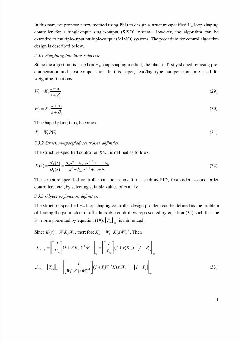
Step responses of the closed loop system using the PD, and the proposed first order controllers
from case one and case two are shown in Fig. 11(a) and Fig. 11(b), respectively. These
simulations show that the proposed controller is robust to the parameter variations in both cases
while the system becomes unstable by using PD controller.
8/4/2019 Balancing Control of Bicyrobo by Particle Swarm Optimization-based Structure-specifield Hoo Loop Shaping Control
http://slidepdf.com/reader/full/balancing-control-of-bicyrobo-by-particle-swarm-optimization-based-structure-specifield 17/22
17
Fig. 11. Step responses from PD, and proposed first order controllers with parameters variation:
(a) Case 1; (b) Case 2
5. Experimental Results
The experiments are conducted on Bicyrobo with the hardware setup as explained in Section 2.
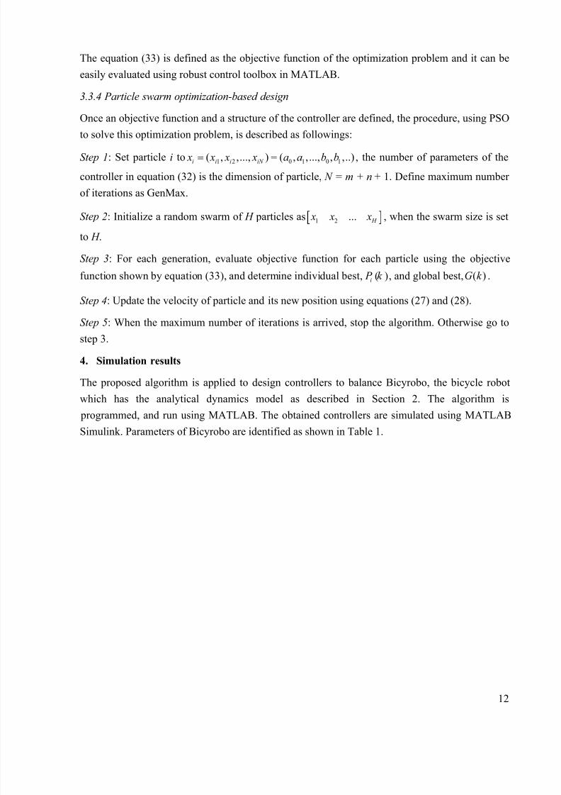
The diagram for implementing the controllers on Bicyrobo is shown in Fig. 12. The program is
coded in C and implemented on PC/104, a 300MHz CPU embedded computer, with sampling
time of 12.5ms. The lean angle of Bicyrobo is read from vertical gyro-sensor VG400CC via an
A/D extended board. The calculated output voltage from a D/A extended board is sent to an
external PWM and Driver circuit to control DC motor of the flywheel control axis. The angular
position of the flywheel control axis (φ) is also read from an E6B-CWZ encoder. In case that the
measured lean angle is zero but Bicyrobo is not at the balancing position, the reference must be
changed to eliminate continuous rotation in one direction of the flywheel.
Fig. 12. Diagram for implementing controllers
Various experiments are conducted to evaluate balancing performance and robustness of the
proposed controllers. The first set of the experiments is tested on the system using the PD and the
proposed first order controllers at a zero forward speed of Bicyrobo without applied masses. The
controllers in equations (38) and (41) are converted to discrete forms (C(z)) and then coded in C

8/4/2019 Balancing Control of Bicyrobo by Particle Swarm Optimization-based Structure-specifield Hoo Loop Shaping Control
http://slidepdf.com/reader/full/balancing-control-of-bicyrobo-by-particle-swarm-optimization-based-structure-specifield 18/22
18
on the embedded PC for testing. The lean angles of the system are saved in a file while program
is running. Fig. 13 depicts balancing performance from the lean angle of Bicyrobo. The results
show that the proposed controller has better balancing performance than the conventional PD
controller.
Fig. 13. Balancing performance
Fig. 14. Balancing performance with load variations
In order to show that the proposed controllers is robust to parameter variations, iron masses of
4kg and 8kg are applied on the system at a zero forward speed of Bicyrobo. The experiments on
Bicyrobo using the proposed first order controller are tested. The experimental results are shown
in Fig. 14. In both cases, the system is stable against these parameter variations. Photographs of
Bicyrobo taken during the experiments with 8kg applied mass are shown in Fig. 15.

8/4/2019 Balancing Control of Bicyrobo by Particle Swarm Optimization-based Structure-specifield Hoo Loop Shaping Control
http://slidepdf.com/reader/full/balancing-control-of-bicyrobo-by-particle-swarm-optimization-based-structure-specifield 19/22
19
Fig. 15. Photographs during experiments with 8kg of applied mass: (a) left view; (b) right view;
(c) front view; (d) back view
6. Conclusion
This paper proposed a PSO-based structure-specified H∞ loop shaping controller design method
to control balancing of Bicyrobo. By using the proposed method, the first order and second order
controllers were designed with the stability margins, εopt , of 0.5445 and 0.55617, respectively.
These stability margins are quite closed to stability margin of the sixth order controller (εopt =
0.6363) designed using the conventional H∞ loop shaping method. The simulation results shown
that performance of the closed loop system using the proposed controllers and full order
controller were similar, they are both better than performance of the closed loop system using PD
controller. The simulation results also shown that the closed loop system was robustly stable to
parameter variations using the proposed controllers, while it was unstable using the PD
controller. The experimental results on Bicyrobo proved that the proposed first order controller
achieved better balancing performance with lean angle less than 0.5 degree in compared to thePD controller with maximum lean angle about 1 degree. Experimental results on applying masses
of 4kg and 8kg on the system using the proposed first order controller shown that the system had
good balancing performance and robustness with lean angle less than 1 degree against the load
variation.
In conclusion, the proposed controllers achieved two important requirements: simple in structure
and good robust performance against uncertainties. The design method is straightforward,

8/4/2019 Balancing Control of Bicyrobo by Particle Swarm Optimization-based Structure-specifield Hoo Loop Shaping Control
http://slidepdf.com/reader/full/balancing-control-of-bicyrobo-by-particle-swarm-optimization-based-structure-specifield 20/22
20
systematic, and simple by using PSO algorithm. Therefore, it is easy to apply to other systems.
The algorithm was demonstrated on a SISO unstable system. But it can be extended to MIMO
systems.

8/4/2019 Balancing Control of Bicyrobo by Particle Swarm Optimization-based Structure-specifield Hoo Loop Shaping Control
http://slidepdf.com/reader/full/balancing-control-of-bicyrobo-by-particle-swarm-optimization-based-structure-specifield 21/22
21
Reference
[1] Murata Boy Robot. Available from http://www.murataboy.com/en/index.html
[2] Beznos AV, Formalsky AM, Gurfinkel EV, Jicharev DN, Lensky AV, Savitsky K V, et
al. Control of autonomous motion of two-wheel bicycle with gyroscopic stabilization. In:
Proceedings of the IEEE international conference on robotics and automation, 1998, p.
2670-5.
[3] Gallaspy JM. Gyroscopic stabilization of an unmanned bicycle, M.S. Thesis, Auburn
University, 1999.
[4] Suprapto S. Development of a gyroscopic unmanned bicycle. M.Eng. Thesis, Asian
Institute of Technology, Thailand, 2006.
[5] Lee S, Ham W. Self-stabilizing strategy in tracking control of unmanned electric bicycle
with mass balance. IEEE international conference on intelligent robots and systems,
2002, p. 2200-5.
[6] Tanaka Y, Murakami T. Self sustaining bicycle robot with steering controller. In:
Proceedings of international workshop on advanced motion control, 2004, p. 193-7.
[7] Wong Terence CF, Hung YS. Stabilization of biped dynamic walking using gyroscopic
couple. IEEE international joint symposia on intelligent and systems, 1996, p. 102-8.
[8] McFarlane D, Glover K. A loop shaping design procedure using H∞ synthesis. IEEE
Trans Automat Contr 1992; 37(6): 759-69.
[9] Chu YC, Glover K, Dowling AP. Control of combustion oscillations via H∞ loop
shaping, µ-analysis and integral quadratic constraints. Automatica 2003; 39(2): 219-31.
[10] Ballois SL, Duc G. H∞ control of a satellite axis: Loop shaping, controller reduction, and
µ-analysis. Contr Eng Practice 1996; 4 (7): 1001-7.
[11] Jayender J, Patel RV, Nikumb S, Ostojic M. H∞ loop shaping controller for shaped
memory alloy actuators. In: Proceedings of the IEEE conference on decision and control,
2005, p. 653-8.
[12] Kaitwanidvilai S, Parnichkun M. Genetic algorithm-based fixed-structure robust H∞ loop
shaping control of a pneumatic servo system. J Robot Mechatron 2004; 16 (4): 362-73.
[13] Fleming PJ, Purshouse RC. Evolutionary algorithms in control systems engineering: a
survey. Contr Eng Practice 2002; 10(9): 1223-41.
[14] Kennedy J, Eberhart R. Particle swarm optimization. In: Proceedings of the IEEE
international conference on neural networks, 1995, p. 1942-8.

8/4/2019 Balancing Control of Bicyrobo by Particle Swarm Optimization-based Structure-specifield Hoo Loop Shaping Control
http://slidepdf.com/reader/full/balancing-control-of-bicyrobo-by-particle-swarm-optimization-based-structure-specifield 22/22
[15] Mukherjee V, Ghoshal SP. Intelligent particle swarm optimized fuzzy PID controller for
AVR system. Electr Power Syst Research 2007; 77(12): 1689-98.
[16] Kao CC, Chuang CW, Fung RF. The self-turning PID control in a slider-crank
mechanism system by applying particle swarm optimization approach. Mechatronics
2006; 16(8): 513-22.
[17] Chang WD. PID control for chaotic synchronization using particle swarm optimization.
Chaos Solitons & Fractals, In Press, Corrected Proof, Available online 8 April 2007.
[18] Sharp RS. The stability and control of motorcycles. J Mechnical Eng Sci 1971; 13(5):
316-29.
[19] Wolfram S. Analytical robotics and mechatronics. New York: McGraw-Hill, 1995.
[20] Tang KS, Man KF, Gu DW. Structured genetic algorithm for robust H∞ control systems
design. IEEE Trans Industrial Electronics 1996; 43(5): 575-82.
[21] Jang Y, et al. An improved particle swarm optimization algorithm. Appl Math Comput,
In Press, Corrected Proof, Available online 27 March 2007.