Embed Size (px)
Citation preview
Balancing of big rotors, processing of frames
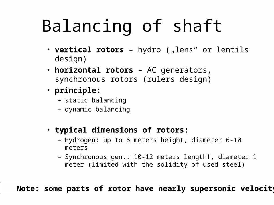
Balancing of shaft • vertical rotors – hydro („lens“ or lentils design)• horizontal rotors – AC generators, synchronous
rotors (rulers design)• principle:
– static balancing– dynamic balancing
• typical dimensions of rotors:– Hydrogen: up to 6 meters height, diameter 6-10 meters– Synchronous gen.: 10-12 meters length!, diameter 1
meter (limited with the solidity of used steel)
Note: some parts of rotor have nearly supersonic velocity!
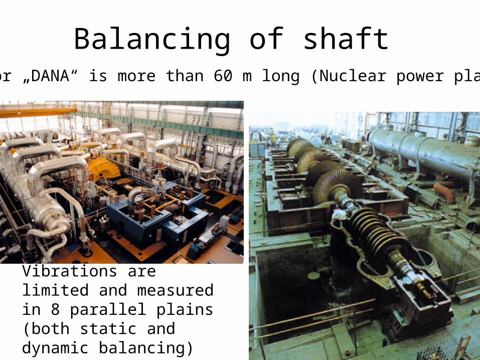
Balancing of shaft Rotor „DANA“ is more than 60 m long (Nuclear power plant)
Vibrations are limited and measured in 8 parallel plains (both static and dynamic balancing)
Balancing of shaft • Centrifuge forces/moments, impact on life-time,
• Caused:• by unbalanced mass (most often)• oval bearings• another reason
• Solution: add/remove the same mass from opposite site (weight/plumb). Typical material – „modeling clay“
• Balancing:• static• dynamic (can be discovered just during rotation)• mixed (both principles)
• Critical runs: unbalanced mass is on the opposite site
Special (long) rotors, turbo-rotors
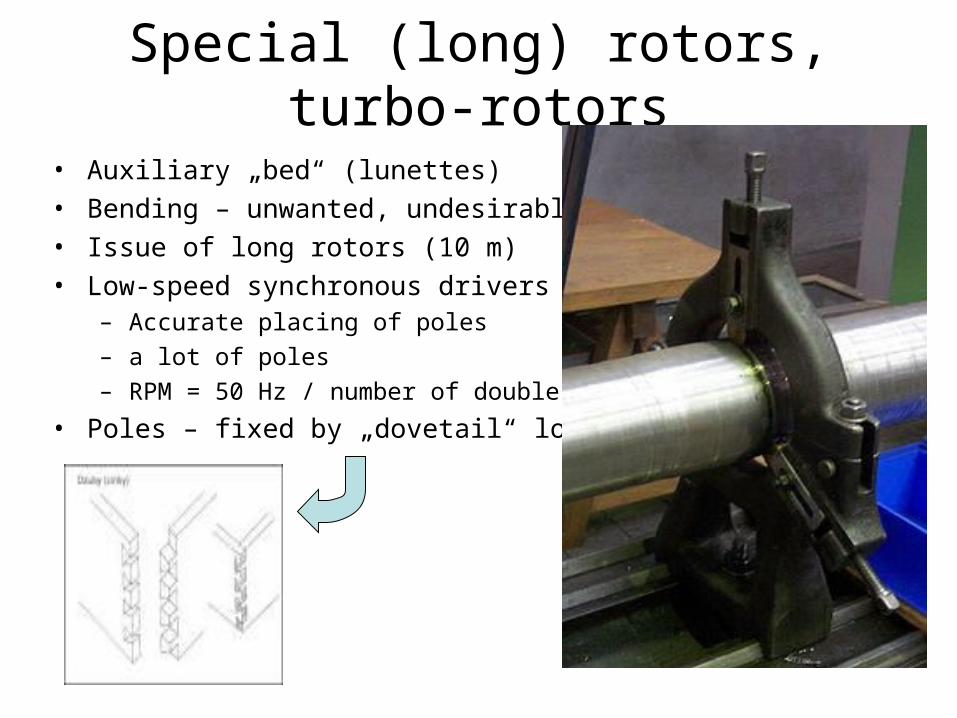
• Auxiliary „bed“ (lunettes) • Bending – unwanted, undesirable• Issue of long rotors (10 m)• Low-speed synchronous drivers
– Accurate placing of poles
– a lot of poles
– RPM = 50 Hz / number of double-poles
• Poles – fixed by „dovetail“ lock
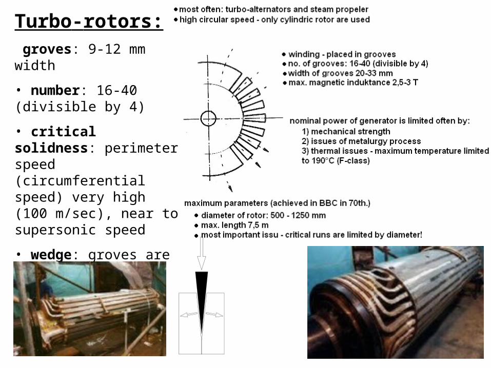
Turbo-rotors: groves: 9-12 mm width
• number: 16-40 (divisible by 4)
• critical solidness: perimeter speed (circumferential speed) very high (100 m/sec), near to supersonic speed
• wedge: groves are fixed by bronze wedge
Machining of frames (AC drivers)
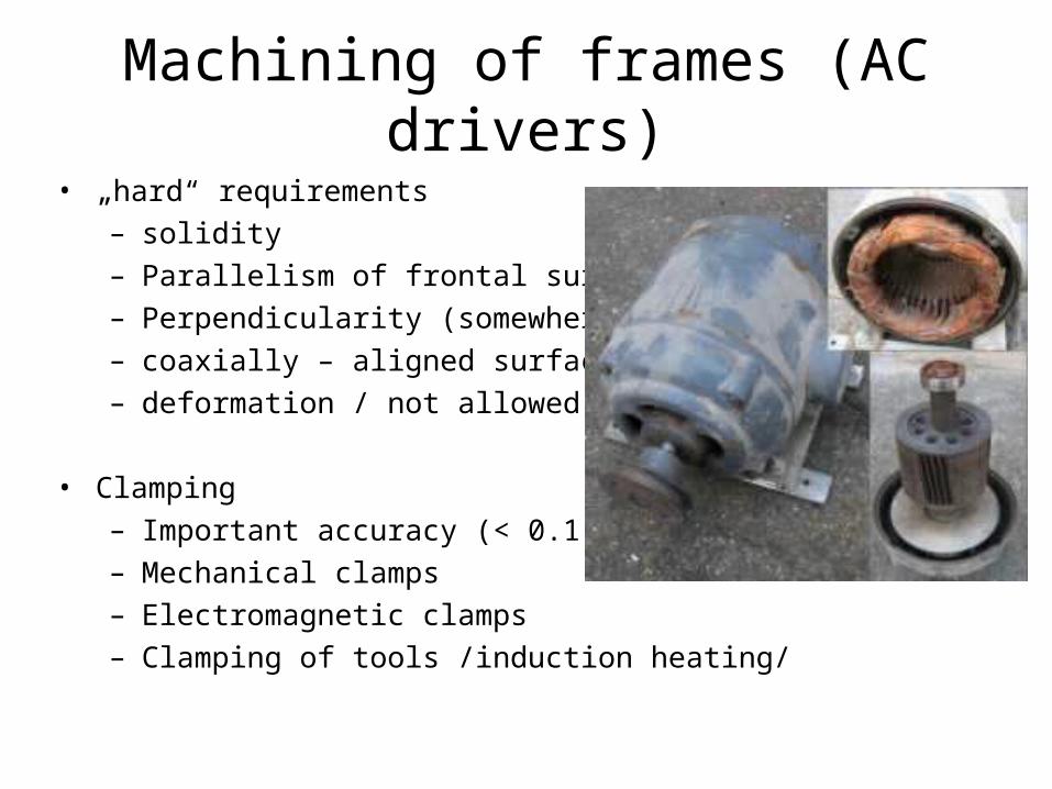
• „hard“ requirements– solidity– Parallelism of frontal surfaces– Perpendicularity (somewhere)– coaxially – aligned surfaces– deformation / not allowed
• Clamping– Important accuracy (< 0.1 mm)– Mechanical clamps– Electromagnetic clamps– Clamping of tools /induction heating/
Processing of frames
• Ageing – important for solidity, often are frames stored outside – climatic stress
• 1st. Basic issue – not rotating parts – difficult to machine• 2nd. Basic issue – accuracy of clamping (fixing)
minimizing of clamps:– Piece production:
• big work pieces – special tools and machines necessary
– Serial production:• often used machining centers with many tools and ONE clamp!
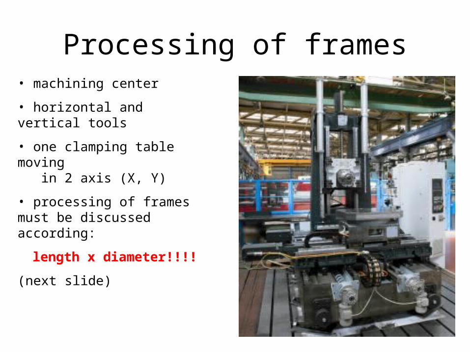
Processing of frames• machining center
• horizontal and vertical tools
• one clamping table moving in 2 axis (X, Y)
• processing of frames must be discussed according:
length x diameter!!!!
(next slide)
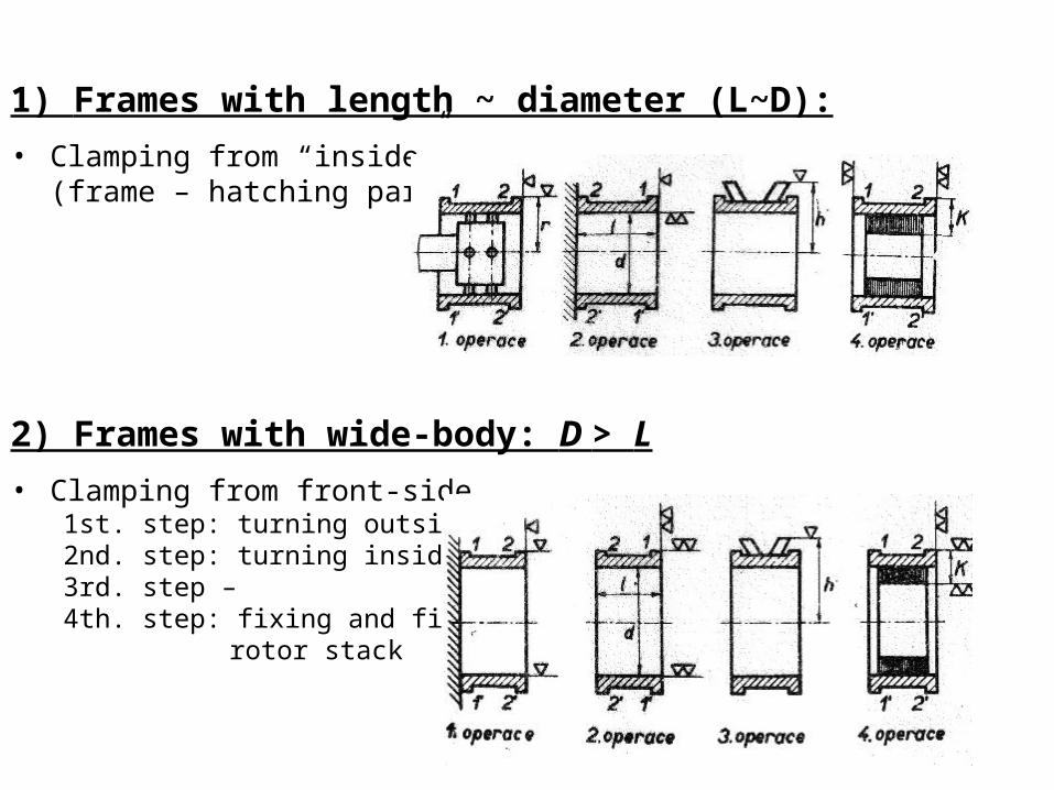
1) Frames with length ~ diameter (L~D):
• Clamping from “inside”(frame – hatching part)
2) Frames with wide-body: D > L
• Clamping from front-side1st. step: turning outside parts2nd. step: turning inside parts3rd. step – 4th. step: fixing and finishing
rotor stack
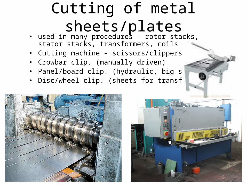
Cutting of metal sheets/plates• used in many procedures – rotor stacks, stator stacks,
transformers, coils etc.• Cutting machine – scissors/clippers• Crowbar clip. (manually driven)• Panel/board clip. (hydraulic, big stress)• Disc/wheel clip. (sheets for transform.)
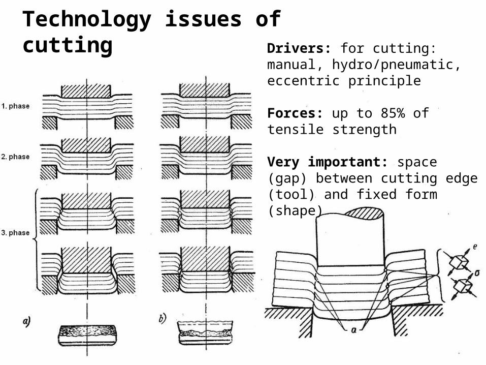
Drivers: for cutting: manual, hydro/pneumatic, eccentric principle
Forces: up to 85% of tensile strength
Very important: space (gap) between cutting edge (tool) and fixed form (shape)
Technology issues of cutting


![UnbalanceResponsePredictionforRotorsonBall ...ing machinery (see, e.g., Wowk [7]). These criteria are also commonly used for moderately flexible rotors. The recom-mended balancing](https://img.pdfslide.net/doc/110x75/609c2564cecc7004d24804dc/unbalanceresponsepredictionforrotorsonball-ing-machinery-see-eg-wowk-7.jpg)