Embed Size (px)
Citation preview

Page 1 55066-03_97_A
EL2001 Mach 3 Hot Sheet
55066-03_97_A.pdf 07/23/2007Template used: 40573-v29-30_D.pdf 07/19/2007
Software Version # 30EPN # n/a (See ECR 6142)Base PCBA – PN 53974-04PCB EL2000 – PN 22896 Rev BHEX File – 10011430
Base PanelsML900 – PN 52654ML700 – PN 52649ML400 – PN 52684
Balboa InstrumentsSystem PN 55066-03
System Model # E2P-EL2001M2-YCAH

Page 2 55066-03_97_A
System Revision History
System PN EPN Date Requested By Changes Made55066-02 2130 11.27.2006 Balboa Software update to v28
55066-03 n/a 07.23.2007 Balboa Software update to v30

Page 3 55066-03_97_A
Additional Options• Full Feature Dolphin Remote
and Spa-only Dolphin Remote
• Spa MonitorConnects to Main Panel terminal J70 or J71 or J72
• IR or RF Dolphin Receiver ModuleConnects to Remote terminal J20
• Ozone GeneratorConnects to terminal J9
• MoodEFX LightingConnects to Spa Light terminal J12
• FiberEFX LightingConnects to Spa Light terminal J12
• Stereo SystemConnects to A.V. terminal J4
U4
ADCM
W12
MAINPANEL
MAINPANEL
MAINPANEL
AUXPANEL
AUXPANEL
J6
J3
W2
REMOTE
J86
J80
J69
J20
J10
J39
J71
J70
J17
J15 J13
J83
J22 J24
J82
J36
SENS. A SENS. B VAC EXT. 2SP PUMP 3 EXT. RLY
AUX. F
J72
GW
Basic System Features and Functions
Power Requirements• 240VAC, 60Hz, 48A, Class A GFCI-protected service (Circuit Breaker rating = 60A max.)
• 4 wires (hot, hot, neutral, ground)
System Outputs
Setup 1 (As Manufactured)• 240V Pump 1, 2-Speed• 240V Pump 2, 2-Speed• 240V Blower, 1-Speed• 120V Ozone• 12V Spa Light• 120V AV (Stereo)• 240V 5.5kW Heater *
Optional Devices• 240V Circ Pump
* Heater wattage is rated at 240V. When running 120V to heater, output is approximately 25%.

Page 4 55066-03_97_A
Persistent Memory and Powering Up
Any time you change DIP Switches or Software Configuration Settings that affect parameters the user can change (any filter settings, set temperature default, Celsius vs Fahrenheit, 12-hour vs 24-hour time, reminders suppression, etc), you must reset Persistent Memory for your DIP Switch or Software Configuration Settings changes to take effect. You should also reset Persistent Memory after loading a new file into a board (using the ESM, purchased seperately).
To reset Persistent Memory:• Power down.• Set A12 ON (See illustration below).• Power up.• Wait until “ ” or “ ” is displayed on your panel.
Note: If “ ” appears see section below.• Set A12 OFF. (This can be done safely with power on if you use a non-
conductive tool such as a pencil to push the switch back to the OFF position. Otherwise, power down before setting A12 OFF)
• Power up again (if you powered down in the previous step).• For all other power ups, leave A12 OFF.
About Persistent Memory and Time of Day Retention:This system uses memory that doesn’t require a battery to store a variety of settings. What we refer to as Persistent Memory stores all the User Preferences, as well as all the filter settings, the set temperature, and the heat mode.
Persistent Memory is not used for Time of Day. Time of Day needs to be “kept running” (not just stored) while the power is off, so a separate Real Time Clock feature (on all models except the EL1000) keeps track of Time of Day while the unit is off. Time of Day Retention, and Time of Day Retention alone, is controlled by the J91 jumper. J91 must be set according to main system panel used.
message on power up:If “ ” appears before (and instead of) “ ” or “ ”, you have not configured DIP Switches and/or Software Configuration Settings in a valid manner. This must be corrected before you can reset Persistent Memory.The switch numbers, jumpers, or configuration settings displayed after “
” are ones with which the system has found a configuration problem. For example:• “ ” would mean that the combination of how you’ve set
A5 and how you’ve set B2 is not supported on this system.• “ ” would mean that there is a problem with jumper J99• “ ” would mean that the combination of how
you’ve set pump 3 for 1-speed and blower for 1-speed is not supported on this system.
• “ ” would mean that the combination of how you’ve set DIP switches which have been assigned to pump 3 and blower is not supported on this system.
Power Up Display SequenceUpon power up, you should see the following on the display:• Three numbers in a row, which are the SSID (the System Software
ID). The third display of these numbers is the Software Version, which should match the version of your system. For example, if these three numbers are , that is a Mach 3 EL8000 at version 26.
• If there is a Configuration Error, the message (see above) will appear at this point (and none of the messages below will display). Otherwise what comes next is:
• An indication of either the input voltage detected (EL1000/EL2000), or the heater wattage range supported (EL8000/GL2000/GL8000).• Heater wattage display: “ ” means the system supports a heater
from 1 kW to 3 kW. “ ” means the system supports a heater from 3 kW to 6 kW. “ ” means the system supports a 3 kW heater only. (These ranges may be modified slightly in the case of special heaters, which the next bullet covers.)
• Input voltage display: A system showing “ ” supports 3 kW to 6 kW heaters. A system showing “ ” supports the very same heaters, although at 120V those heaters will function at only 1/4 of their 240V rated wattage. (The system shows only either “ ” or “ ” as a general indication of input voltage; it does not show the actual input voltage.)
• If your system is using a special type of heater, a display such as “ ”may appear next. If your system is using the generic Balboa heater, no heater type display will appear.
• “ ” or “ ” will appear to signal the start of Priming Mode.
At this point, the power up sequence is complete. Refer to the User Guide for the ML Series panel on your system for information about how the spa operates from this point on.
Switchbank A Switchbank B
J91 J91RTC
Disabled(Jumpered)
RTCEnabled
(Not Jumpered)

Page 5 55066-03_97_A
RED AC
WHT AC
J53
J23 J19 J43 J48
K12
U4
J50J52
BLK AC
J66 J65 J63J64 J42
J54 J56J55
J25J57 J26
TB1
CLASS GFUSE 30A
CLAS
SG
FUSE
30A
F6
F7
F4
K4
W1
F2
K7
T1
HTR2 HTR1
FUSE0.3A 250V
K6
K8
G RBW
J79J
J46
J45
J81
12VAC
ADCM
J37J37
J4 J7J7J7
4
W8
1
2
3 FUSE3A 250V
TORQUERANGEFOR TB1:27-30 IN. LBS.
HOTBLACK
NEUTRALW
HITEHOTRED
Balboa
J11J11 J8J8
BARCODE
GR
BW
W W J12
J14
W13 W12
K13
W20
W15
BALBOA INSTRUMENTS, INC. MADE IN U.S.A.EL2000 TC MACH III COPYRIGHT 2005P/N 22896 REV B
K10
J2
MAINPANEL
MAINPANEL
MAINPANEL
AUXPANEL
AUXPANEL
J9
J5
J6
K3
J3
K2
W2
F5
W9 W7
REMOTE
K11
K9
J1
K1
GR
BW
GR
BW G
RB
W
J86
J80
J60J60
J69
J20
J10
FUSE 10A 250V
J39
J71
J70
J98
J98
J89
J91
J17
J15 J13
J83
J22 J24
J82
J36
TST
SENS. A SENS. B VAC EXT. 2SP PUMP 3 EXT. RLY
AUX. F
J72
CFG
SWITCHBANK A SWITCHBANK B
J90
J977
GR
BW
J85J85J85
GR B W
J6
J3J2
W12K1
F10A 250VF5X-B
PN 53310
Blower
RTC Enabled
5.5 kW
A.V.Use AUX Board
for BlowerWith 2-Speed P2
Use X-B Expanderfor Blower
With 2-Speed P22-Spd P2
Ozone
Circ.Pump12V Light
SpaLight
2-Spd P1
Wiring Configuration and DIP Settings
Setup 1 (As Manufactured)• 240V Pump 1, 2-Speed• 240V Pump 2, 2-Speed• 240V Blower, 1-Speed
• 240V Circ Pump (Optional)• 12V Spa Light• 120V Ozone
• 120V A\V (Stereo)• 240V 5.5kW Heater• ML900 or ML700 Main Panel
120 Volt Connections
240 Volt Connections
Black AC Jumpers
12 Volt Connections
Relay Control Wires
Wiring Color Key
Typically Line voltage
Typically Line voltage for 2-speed pumps
Neutral (Common)
Ground
Note flat sides in connector
1
2
3
4
Board Connector Key
WARNING: Main Power to system should be turned OFF BEFORE adjusting DIP switches.WARNING: Persistent Memory (A12) must be RESET to allow new DIP switch settings to take effect. (See Persistent Memory page)
Switchbank A Switchbank B
A2, Low Amp
A5, Degrees FA6, Short Timeouts
A9/A10,No Circ PumpA9/A10,No Circ Pump
A1, Test Mode OFF
A3, Filter by TimeA4, 12 Hr Time
A7, Cleanup Cycle OFFA8, 1Hr O3 Supress OFF
A12, Memory Retained
B1, Pump 2 2-SpeedB2, Pump 2 DisabledB3, Blower DisabledB4, No Fiber/WheelB5, Pump 3 Disabled B6, Panel Scrunching OFF
10011430
SSID #
J37
3
2
1
12 VLight
J91RTC
Enabled(Not Jumpered)
B3, Blower EnabledB2, Pump 2 Enabled
A11, O3 w/ P1 Lowand P1 is 2-Spd
A2, High Amp
J17
J15J83
J22
AUX.F
SENS. A
TST
CFGWhen the Logic Jumper is not installed on J83 (CFG),DIP Switch Settings are enabled.DIP Switches will then operate as shown below.
Page 6 55066-03_97_A
DIP Switches and Jumpers Definitions
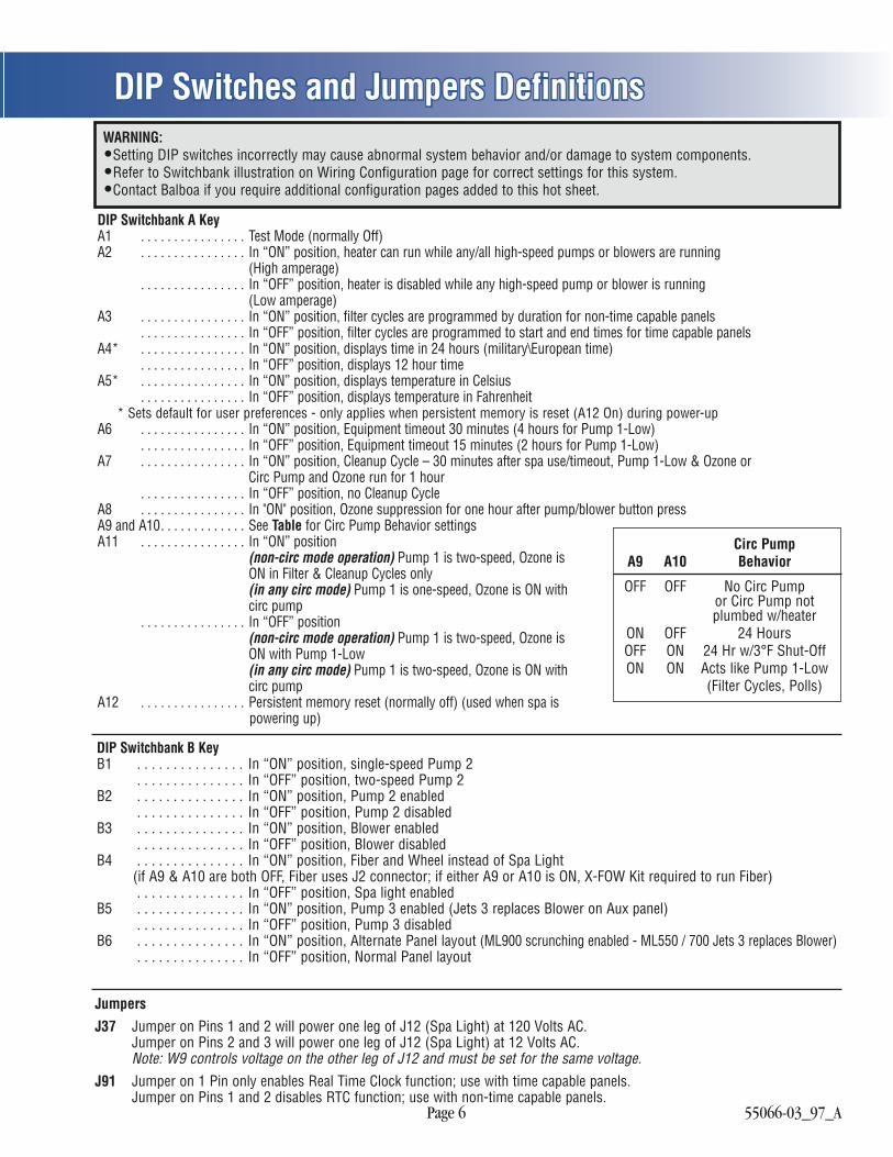
DIP Switchbank A KeyA1 . . . . . . . . . . . . . . . . Test Mode (normally Off)A2 . . . . . . . . . . . . . . . . In “ON” position, heater can run while any/all high-speed pumps or blowers are running (High amperage)
. . . . . . . . . . . . . . . . In “OFF” position, heater is disabled while any high-speed pump or blower is running (Low amperage)A3 . . . . . . . . . . . . . . . . In “ON” position, filter cycles are programmed by duration for non-time capable panels
. . . . . . . . . . . . . . . . In “OFF” position, filter cycles are programmed to start and end times for time capable panelsA4* . . . . . . . . . . . . . . . . In “ON” position, displays time in 24 hours (military\European time)
. . . . . . . . . . . . . . . . In “OFF” position, displays 12 hour timeA5* . . . . . . . . . . . . . . . . In “ON” position, displays temperature in Celsius
. . . . . . . . . . . . . . . . In “OFF” position, displays temperature in Fahrenheit* Sets default for user preferences - only applies when persistent memory is reset (A12 On) during power-up
A6 . . . . . . . . . . . . . . . . In “ON” position, Equipment timeout 30 minutes (4 hours for Pump 1-Low) . . . . . . . . . . . . . . . . In “OFF” position, Equipment timeout 15 minutes (2 hours for Pump 1-Low)
A7 . . . . . . . . . . . . . . . . In “ON” position, Cleanup Cycle – 30 minutes after spa use/timeout, Pump 1-Low & Ozone or Circ Pump and Ozone run for 1 hour
. . . . . . . . . . . . . . . . In “OFF” position, no Cleanup CycleA8 . . . . . . . . . . . . . . . . In "ON" position, Ozone suppression for one hour after pump/blower button pressA9 and A10. . . . . . . . . . . . . See Table for Circ Pump Behavior settingsA11 . . . . . . . . . . . . . . . . In “ON” position (non-circ mode operation) Pump 1 is two-speed, Ozone is ON in Filter & Cleanup Cycles only (in any circ mode) Pump 1 is one-speed, Ozone is ON with circ pump
. . . . . . . . . . . . . . . . In “OFF” position (non-circ mode operation) Pump 1 is two-speed, Ozone is ON with Pump 1-Low (in any circ mode) Pump 1 is two-speed, Ozone is ON with circ pumpA12 . . . . . . . . . . . . . . . . Persistent memory reset (normally off) (used when spa is powering up)
Circ Pump A9 A10 Behavior
OFF OFF No Circ Pump or Circ Pump not plumbed w/heaterON OFF 24 HoursOFF ON 24 Hr w/3°F Shut-OffON ON Acts like Pump 1-Low (Filter Cycles, Polls)
JumpersJ37 Jumper on Pins 1 and 2 will power one leg of J12 (Spa Light) at 120 Volts AC.
Jumper on Pins 2 and 3 will power one leg of J12 (Spa Light) at 12 Volts AC.Note: W9 controls voltage on the other leg of J12 and must be set for the same voltage.
J91 Jumper on 1 Pin only enables Real Time Clock function; use with time capable panels.Jumper on Pins 1 and 2 disables RTC function; use with non-time capable panels.
DIP Switchbank B KeyB1 . . . . . . . . . . . . . . . In “ON” position, single-speed Pump 2
. . . . . . . . . . . . . . . In “OFF” position, two-speed Pump 2B2 . . . . . . . . . . . . . . . In “ON” position, Pump 2 enabled
. . . . . . . . . . . . . . . In “OFF” position, Pump 2 disabledB3 . . . . . . . . . . . . . . . In “ON” position, Blower enabled
. . . . . . . . . . . . . . . In “OFF” position, Blower disabledB4 . . . . . . . . . . . . . . . In “ON” position, Fiber and Wheel instead of Spa Light (if A9 & A10 are both OFF, Fiber uses J2 connector; if either A9 or A10 is ON, X-FOW Kit required to run Fiber)
. . . . . . . . . . . . . . . In “OFF” position, Spa light enabledB5 . . . . . . . . . . . . . . . In “ON” position, Pump 3 enabled (Jets 3 replaces Blower on Aux panel)
. . . . . . . . . . . . . . . In “OFF” position, Pump 3 disabledB6 . . . . . . . . . . . . . . . In “ON” position, Alternate Panel layout (ML900 scrunching enabled - ML550 / 700 Jets 3 replaces Blower)
. . . . . . . . . . . . . . . In “OFF” position, Normal Panel layout
WARNING:•Setting DIP switches incorrectly may cause abnormal system behavior and/or damage to system components.•Refer to Switchbank illustration on Wiring Configuration page for correct settings for this system.•Contact Balboa if you require additional configuration pages added to this hot sheet.

Page 7 55066-03_97_A
Ozone Connections
K12
U4
J45 W
13 W12
W20
W15
BALBOA INSTRUMENTS, INC. MADE IN U.S.A.EL2000 TC MACH III COPYRIGHT 2005P/N 22896 REV B
K10
2 AUXPANEL
AUXPANEL
J9
J5
K3
J3
K2
W2
F5
K9
GW
GW
J86
J60
J10
FUSE 10A 250V
J39
0
J98
J90
J97
GW
J85
Use this slot for the leftover Red conductorLine - Black conductor
Balboa Ozone connector configuration for 120V 60Hz
Ground (Green) conductor
Flat sides of sockets as shown
Common - Install the White conductor here for 120V ozone
Use this slot for the leftover White conductorLine - Black conductor
Balboa Ozone connector configuration for 240V 60Hz
Ground (Green) conductorCommon - Install the Red conductor here for 240V ozone
B
G
B
G
Use this slot for the leftover conductorLine - Black conductor
Ground (Green) conductor
Common - Red for 240V or White for 120V ozone (See W13 wire)
W13 wire determines voltage
Ozone Connector Voltage: The EL circuit board is factory configured to deliver a preset voltage (120V or 240V) to the on-board ozone connector (J9). See the ratings table on the wiring diagram attached to the cover of the enclosure for the configured voltage. For 240V output W13 connects to Red AC and for 120V output W13 connects to White AC.
The voltage to the ozone connector can be changed in the field if required. W13 just needs to be set for the required voltage.
Balboa Ozone Generator: If the board is set up to operate a 120V ozone generator, the connector on the ozone generator is likely to be configured correctly, but should be compared to the illustration below.
If a 240V ozone generator is required, be sure the red wire in the ozone cord is positioned in the connector next to the green ground wire as described below.
Note: A special tool is required to remove the pins from the connector body once they are snapped in place. Check with your Balboa Account Manager for information on purchasing a pin-removal tool.
Page 8 55066-03_97_A
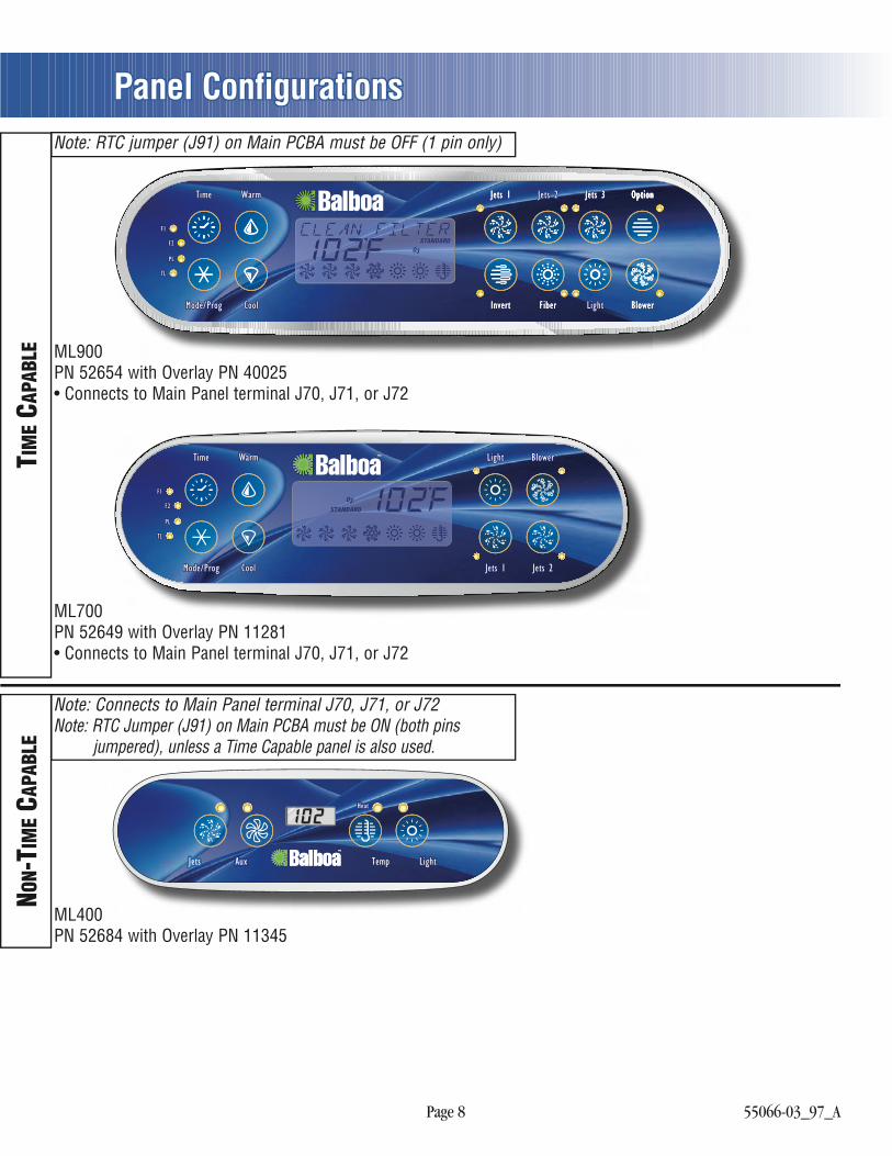
Panel Configurations
ML400PN 52684 with Overlay PN 11345
NON-
TIM
E CAP
ABLE
Heat
Jets Aux Temp Light
Cool
WarmTime
Mode/Prog
Blower
Jets 2
Light
Jets 1
F2
TL
F1
PL
Jets 3 OptionJets 1 Option
Invert BlowerFiber
Jets 3 OptionTime Warm Jets 1 Jets 2 Jets 3 Option
CoolMode/Prog Invert BlowerFiber Light
F2
TL
F1
PL
ML700PN 52649 with Overlay PN 11281• Connects to Main Panel terminal J70, J71, or J72
TIM
E CAP
ABLE
Note: RTC jumper (J91) on Main PCBA must be OFF (1 pin only)
Note: Connects to Main Panel terminal J70, J71, or J72Note: RTC Jumper (J91) on Main PCBA must be ON (both pins
jumpered), unless a Time Capable panel is also used.
ML900PN 52654 with Overlay PN 40025• Connects to Main Panel terminal J70, J71, or J72