Embed Size (px)
Citation preview
* S UTI~ L C2P00rw% AFOEHL REPORT 89-023RCO111DRA
0
Base Level Management of Radio FrequencyRadiation Protection Program
STEVEN E. RADEMACHER, 1Lt, USAF, BSCNOEL D. MONTGOMERY, 2Lt, USAF, BSC
APRIL 1989 D I Y ,
Final Reportu S
Distribution Is unlimited; approved for public release
AF Occupational and Environmental Health Laboratory (AFSC)Human Systems Division
Brooks Air Force Base, Texas 78235-5501
Supersedes USAFOEHL Report 80-42
8 29 076
NOTICES
When Government drawings, specifications, or other data are used for anypurpose other than a definitely related Government procurement operation, the
Government incurs no responsibility or any obligation whatsoever. The factthat the Government may have formulated, or in any way supplied the drawing,specifications, or other data, is not to be regarded by implication, or
otherwise, as in any manner licensing the holder or any other person orcorporation; or conveying any rights or permission to manufacture, use, orsell any patented invention that may in any way be related thereto.
The mention of trade names or commercial products in this publication is forillustration purposes and does not constitute endorsement or recommendation
for use by the United States Air Force.
The Public Affairs Office has reviewed this report, and it is releasable to
the National Technical Information Service, where it will be available to thegeneral public, including foreign nations.
This report has been reviewed and is approved for publication.
STEVEN E. RADEMACHER, ILt, USAF, BSC EDWARD F. MAHER, LtCol, USAF, BSC
Coisultant, Nonionizing Radiation Chief, Radiation Services Division
Air Force installations may direct requests for copies of this report to:AF Occupational and Environmental Health Laboratory (AFOEHL) Library, Brooks
AFB TX 78235-5501.
Other Government agencies and their contractors registered with the DTICshould direct requests for copies of this report to: Defense TechnicalInformation Center (DTIC), Cameron Station, Alexandria VA .22304-6145.
JAMES C. ROCK, Colonel, USAF, BSC
Commander
INIA qS SFTIED
SECURITY CLASSFICATION OF THIS PAGE
REPORT DOCUMENTATION PAGEla. REPORT SECURITY CLASSIFICATION lb. RESTRICTIVE MARKINGS
Unclassified None2a SECURITY CLASSIFICATION AUTHORITY 3. DISTRIBUTION/ AVAILABILITY OF REPORTN/A Unlimited. Available for Public Release.
2b. DECLASSIFICATION /DOWNGRADING SCHEDULEN/A
4. PERFORMING ORGANIZATION REPORT NUMBER(S) S. MONITORING ORGANIZATION REPORT NUMBER(S)
89-023RC011 iDRA N/A
6a. NAME OF PERFORMING ORGANIZATION 6b. OFFICE SYMBOL 7a. NAME OF MONITORING ORGANIZATIONAF Occupational and Environ- (If applicable) N/A
mental Health Laboratory RZC
6c- ADDRESS (City, State, and ZIP Code) 7b. ADDRESS (City, State, and ZIP Code)
Brooks AFB TX 78235-5501 N/A
' NAME OF FUNDING /SPONSORING 8b. OFFICE SYMBOL 9. PROCUREMENT INSTRUMENT IDENTIFICATION NUMBERORGANIZATION (If applicable)
NIA N/A N/A
Bc. ADDRESS (City, State, and ZIP Code) 10. SOURCE OF FUNDING NUMBERS
N/A PROGRAM PROJECT TASK iWORK UNITELEMENT NO. NO. NO. ACCESSION NO.
II TITLE (Include Security Classification)
Base Level Management of Radio Frequency Radiation Protection Program (Unclassified)
12. PERSONAL AUTHOR(S)* ILt Steven E. Rademacher, 2Lt Noel D. Montgomery
13a. TYPE OF REPORT 13b. TIME COVERED 14. DATE OF REPORT (Year, Month, Day) S. PAGE COUNTFinal FROM TO April 1989 11016. SUPPLEMENTARY NOTATION
17. COSATI CODES 18. SUBJECT TERMS (Continue on reverse if necessary and identify by block number)
FIELD GROUP SUB-GROUP Radio Frequency Hazard Distance Peak PowerAntenna, Radar Average PowerPower Density Antenna Gain NARDA.
19. ABSTRACT (Continue on reverse if necessary anC identify by block number)
AFOEHL developed this report to assist the base level aerospace medical team manage their
radio frequency radiation protection program. This report supersedes USAFOEHL Report
80-42, 'IA Practical R-F Guide for BEES.j
20. DISTRIBUTION /AVAILABILITY OF ABSTRACT 21. ABSTRACT SECURITY CLASSIFICATION*]UNCLASSIFIED/UNLIMITED 0 SAME AS RPT. 0 DTIC USERS Unclassified
22a. NAME OF RESPONSIBLE INDIVIDUAL 22b. TELEPHONE (include Area Code) 22c. OFFICE SYMBOLILt Steven E. Rademacher -0(512)536-386 RZC _
00 FORM 1473.84 MAR 83 APR edition may be used until exhausted. SECRITY CLASSIFICATION OF HIS PAGE
All other editions are obsolete.
i UNCLASSIFIED
CONTENTS
Page
DD Form 1473 .......................................................... i
ILLUSTRATIONS ........................................................ iv
I. INTRODUCTION .......................................................... 1
II. RFR IN THE AIR FORCE .................................................. 1
III. UNDERSTANDING RFR ..................................................... 3
IV. THE HAZARDS .......................................................... 19
V. STANDARDS ............................................................ 22
VI. BASE PROGRAM......................................................... 27
VII. INSTRUMENTATION ... ................................................... 34
VIII. THE RFR ACCIDENT ..................................................... 39
IX. THE VOICE OF EXPERIENCE .............................................. 42
O APPENDIX
A Conversion Between Absolute Units and Decibel Units ............ 43B Instructions for Completing the AF Form 2759, Radiofrequency
Emitter Survey ................................................. 47
C RFR Emitter Survey Data Base ................................... 53D Survey of Ground Based Emitters ................................ 65E Survey of Airborne Emitters .................................... 69F Survey of Medical RFR Emitter .................................. 73
G Radio Frequency Radiation Survey Checklist ..................... 77H Typical Beam Pattern Shape, Gain, anA Beam Widths for Common
Antennas ....................................................... 81
I Basic Emitter Evaluations With Detail-,' Calculations ........... 91J Terms List ..................................................... 99
Distribution ............................ , -,= . ... 105Acoession For
TIS GRA&IDTIC TABUnanneunsol [;ustifleatIton--
~~By....
Distribjtlon/_
Availol)lit' Codes9j
i---st Special "
. . u un nI
ILLUSTRATIONS
TABLE Page
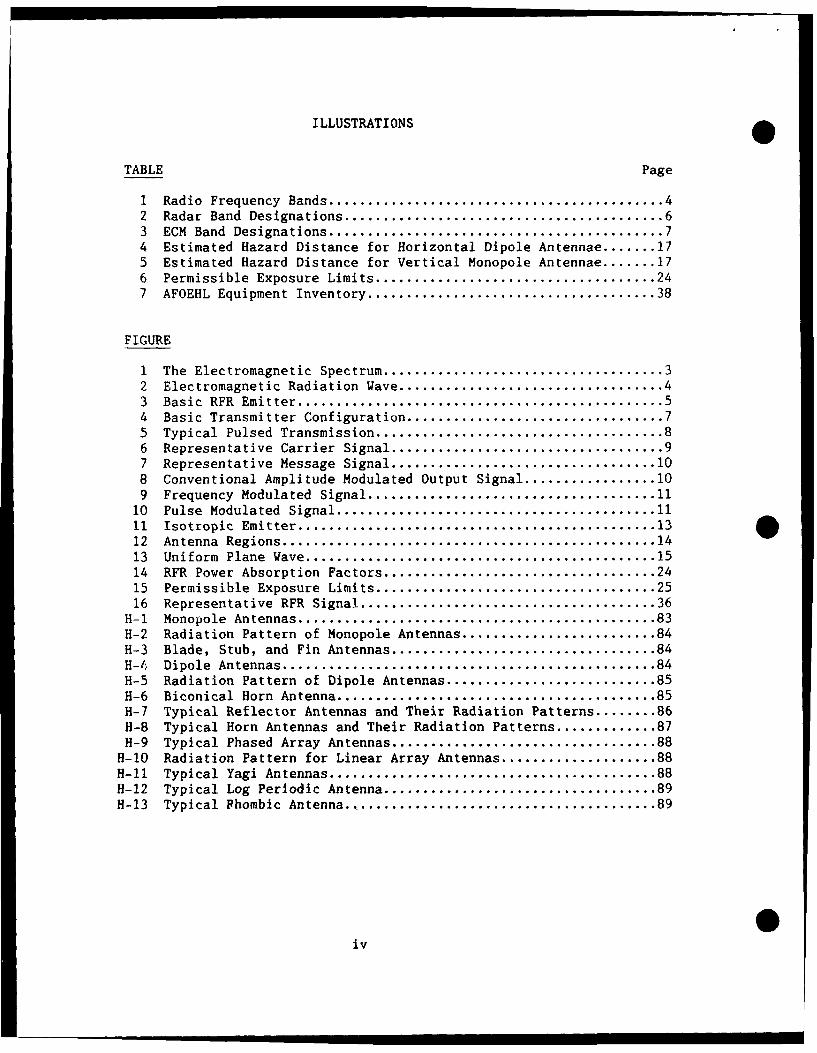
I Radio Frequency Bands ........................................... 42 Radar Band Designations ......................................... 63 ECM Band Designations ........................................... 74 Estimated Hazard Distance for Horizontal Dipole Antennae ....... 175 Estimated Hazard Distance for Vertical Monopole Antennae ....... 176 Permissible Exposure Limits .................................... 247 AFOEHL Equipment Inventory ..................................... 38
FIGURE
I The Electromagnetic Spectrum .................................... 32 Electromagnetic Radiation Wave .................................. 43 Basic RFR Emitter ............................................... 54 Basic Transmitter Configuration ................................. 75 Typical Pulsed Transmission ..................................... 86 Representative Carrier Signal ................................... 97 Representative Message Signal .................................. 108 Conventional Amplitude Modulated Output Signal ................. 109 Frequency Modulated Signal ..................................... 11
10 Pulse Modulated Signal ......................................... 1111 Isotropic Emitter .............................................. 1312 Antenna Regions ................................................ 1413 Uniform Plane Wave ............................................. 1514 RFR Power Absorption Factors ................................... 2415 Permissible Exposure Limits .................................... 2516 Representative RFR Signal ...................................... 36
H-1 Monopole Antennas .............................................. 83H-2 Radiation Pattern of Monopole Antennas ......................... 84H-3 Blade, Stub, and Fin Antennas .................................. 84H-4 Dipole Antennas ................................................ 84H-5 Radiation Pattern of Dipole Antennas ........................... 85H-6 Biconical Horn Antenna ......................................... 85H-7 Typical Reflector Antennas and Their Radiation Patterns ........ 86H-8 Typical Horn Antennas and Their Radiation Patterns ............. 87H-9 Typical Phased Array Antennas .................................. 88
H-10 Radiation Pattern for Linear Array Antennas .................... 88H-lb Typical Yagi Antennas .......................................... 88H-12 Typical Log Periodic Antenna ................................... 89H-13 Typical Phombic Antenna ........................................ 89
0iv
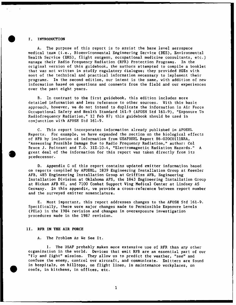
O T. INTRODUCTION
A. The purpose of this report is to assist the base level aerospacemedical team (i.e., Bioenvironmental Engineering Service (BES), EnvironmentalHealth Service (EHS), flight surgeon, occupational medicine consultants, etc.)manage their Radio Frequency Radiation (RFR) Protection Programs. In theoriginal version of this guidebook, the authors attempted to compile a bookletthat was not written in stuffy regulatory dialogue; they provided BEEs withmost of the technical and practical information necessary to implement theirprograms. In the second edition, our intent is the same, with addition of newinformation based on questions and comments from the field and our experiencesover the past eight years.
B. In contrast to the first guidebook, this edition includes moredetailed information and less reference to other sources. With this basicapproach, however, we do not intend to duplicate the information in Air ForceOccupational Safety and Health Standard 161-9 (AFOSH Std 161-9), "Exposure ToRadiofrequency Radiation," 12 Feb 87; this guidebook should be used inconjunction with AFOSH Std 161-9.
C. This report incorporates information already published in AFOEHLReports. For example, we have expanded the section on the biological effectsof RFR by inclusion of information from USAFOEHL Report 86-020CO111BRA,"Assessing Possible Damage Due to Radio Frequency Radiation," author: ColBruce J. Poitrast and T.O. 31Z-10-4, "Electromagnetic Radiation Hazards." A
* great deal of the information for this report was taken directly from itspredecessor.
D. Appendix C of this report contains updated emitter information basedon reports compiled by AFOEHL, 1839 Engineering Installation Group at KeeslerAFB, 485 Engineering Installation Group at Griffiss AFB, EngineeringInstallation Division at Oklahoma AFS, the 1843 Engineering Installation Groupat Hickam AFB HI, and 7100 Combat Support Wing Medical Center at Lindsey ASGermany. In this appendix, we provide a cross-reference between report numberand the surveyed emitter nomenclature.
E. Most important, this report addresses changes to the AFOSH Std 161-9.Specifically, there were major changes made to Permissible Exposure Levels(PELs) in the 1984 revision and changes in overexposure investigationprocedures made in the 1987 revision.
11. RFR IN THE AIR FORCE
A. The Problem As We See It.
1. The USAF probably makes more extensive use of RFR than any otherorganization in the world. Devices that emit RFR are an essential part of our"fly and fight" mission. They allow us to predict the weather, "see" andconfuse the enemy, control our aircraft, and communicate. Emitters are foundin hospitals, on hilltops, on flight lines, in maintenance workplaces, onroofs, in kitchens, in offices, etc.
1
2. For many Air Force personnel, some exposure to RFR is "just part
of the job"; for others, exposures are very rare. It is true almost allroutine expo utes today are at very low levels,2 with power densities much lessthan 1 mW/cm . But levels as high as 100 mW/cm can be found in some areas.AFOSH Std 161-9 specifies occupational limits for RFR above which workers maynot be exposed.
3. RFR is often hard to deal with because it is deceptive. Antennasof varying size and shape hide behind radomes with emissions normallyundetectable to the senses. Large antenna structures are often relativelyharmless, while smaller antennas may create significant hazards. Many factorscan alter the power density produced by an emitter. It is often difficult toaccurately predict the location of a hazard unless the surveyor understandsthe terrain su.,ouitding the site, operational use of the device, accessibilityof personnel, and the operational parameters of the system.
4. But even with the complexities of RFR, the possibility of exposure
to excessive levels of RFR need not be a major concern. In most cases, themeans of adequate protection are quite simple. This is where the BEE andstaff enter the picture.
B. The BES Role.
1. The base bioenvironmental engineer and technicians are chargedwith conducting an RFR protection program as specified in AFOSH Std 161-9;
basically a safety and health effort that identifies and controls all areaswhere the potential for exposures to RFR above the Permissible Exposure Limits(PELs) exist. The nuts and bolts of the program are straightforward:
a. Compile an inventory of emitters.
b. Determine which emitters require a site inspection survey.
c. Determine which emitters require a measurement survey.
d. Evaluate present measures and recommend other control measuresbased on emitter characteristics and survey data.
e. Periodically visit each workplace to verify implementation ofcontrol measures and note changes that will impact required control measures.
2. Unfortunately, the program usually stops here. No matter how
complete your inventory is, how dedicated you are to your survey plan, howmuch you conclude and recommend, the RFR protection program will not be
effective unless you take the time to be an educator. Based on AFOEHLevaluation of suspected overexposure investigation reports, the major reasonfor the rising number of suspected overexposure incidents within the Air Forceis lack of training, rather than lack of survey. Insufficient RFR safety
education produces workers that are poorly informed on the "real" hazards ofRFR. The unfortunate results are anxiety, fear of the unknown, lost
productivity, and possible physical injury.
0
.... . • , .-mm2
3. While the principle tasking rests with the EHS, RFR hazardeducation should be a joint effort between unit radiation protectionofficers, EHS, and BES. While the effort may be time consuming, the payoff isa successful and effective RFR protection program.
III. UNDERSTANDING RADIO FREQUENCY RADIATION
A. The Electromagnetic Spectrum.
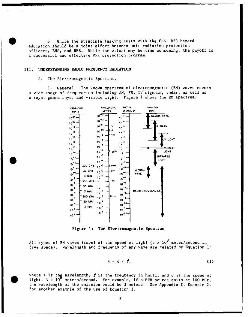
1. General. The known spectrum of electromagnetic (EM) waves covers
a wide range of frequencies including AM, FM, TV signals, radar, as well asx-rays, gamma rays, and visible light. Figure 1 shows the EM spectrum.
FREQUENCY. WAVELENGTH. PHOTON RAOIATION
HERTZ METERS ENERGY, .V TYPE
101 10 7 GAMMA RAYS
1012 10
10 19- to-010 5 JI -RAY
10-
- O 10 A_ RAYS10 17- 10 - 4o
- i A10- 1010's 10e __It 10'
4-.---- "
1 - - 10 -- 10 2 -GHT
10 s- 0-, 10 " .I..
to 15 10 10 - ISI91LE
1014- 10 -- 1 - LIGHT
3 10 10-- INFRARED10 1 10
- 2- LIGHT
11-- 300 GHz 10.4 - o 310 - 1-a
-
30 GHz -2 1cm 10 MICRO-
109--3 GHz 10 - 1
- 10 -
6- WAVE
10 - 300 MHz I - rn
10 30 MHz 10
1 0 7 1 0 1 0 -7 - - A I R Q E C E
106
M 10 10-a- R
10 300 KHz Im 3 1k 10
10 - 10 -
to 4 - 30 KHz 10 4 1-0
10 - 3 KHz 102 10 1 A R
10 10 1 -
Figure 1 The Electromagnetic Spectrum
All types of EM waves travel at the speed of light (3 x 10⁸ meter/second in
free space). Wavelength and frequency of any wave are related by Equation 1:
X = c / f, (1)
where X is thg wavelength, f is the frequency in hertz, and c is the speed of
10 1
light, 3 x 10 meterssecond. For example, if a RFR source emits at 00 MHz,
the wavelength of the emission would be 3 meters. See Appendix I, Example 2,
for another example of the use of Equation 1.
3
2. Radio Frequency Radiation (RFR). RFR is just a part of the EMspectrum that extends in frequency from 10 kilohertz to 300 gigahertz.Table 1 defines the radio frequency bands. Unlike x- and gamma radiation, RFRis nonionizing. The energy of any photon is insufficient to dislodge orbitalelectrons and produce ion pairs. This important distinction is not wellunderstood by many people who equate all types of "radiation." Biologically,the effectc of ionizing and nonionizing radiation are totally different.
Table 1: Radio Frequency Bands
Band Description Frequency
ELF Extremely Low Frequencies 30 - 300 HzVF Voice Frequencies 0.3 - 3 kHzVLF Very Low Frequencies 3 - 30 kHzLF Low Frequencies 30 - 300 kHzMF Medium Frequencies 0.3 - 3 MHzHF High Frequencies 3 - 30 MHzVHF Very High Frequencies 30 - 300 MHz
UHF Ultra High Frequencies 0.3 - 3 GHzSHF Super High Frequencies 3 - 30 GHzEHF Extremely High Frequencies 30 - 300 GHz
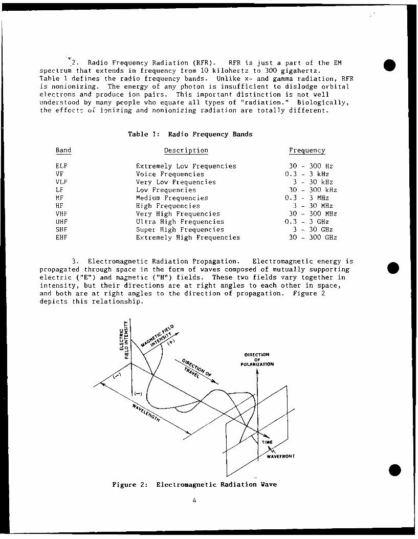
3. Electromagnetic Radiation Propagation. Electromagnetic energy ispropagated through space in the form of waves composed of mutually supportingelectric ("E") and magnetic ("H") fields. These two fields vary together inintensity, but their directions are at right angles to each other in space,
and both are at right angles to the direction of propagation. Figure 2depicts this relationship.
UZ
W /DIRECTIONU. Of
POLARIZATION
WAVEFRONT
Figure 2: Electromagnetic Radiation Wave
4
4. More in-depth details about electromagnetic radiation can be found
in T.O. 31Z-10-4 and AFOSH Std 161-9.
B. Emitters.
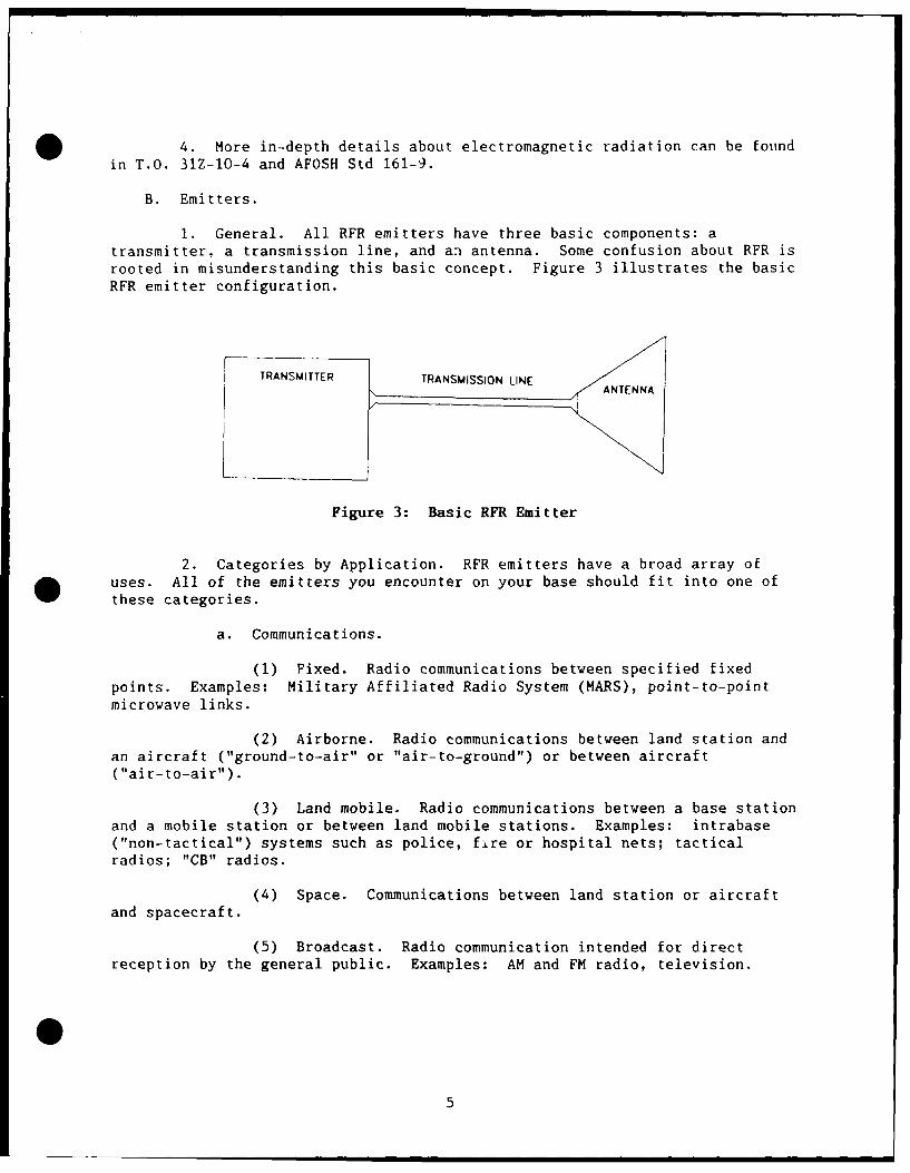
1. General. All RFR emitters have three basic components: a
transmitter, a transmission line, and an antenna. Some confusion about RFR isrooted in misunderstanding this basic concept. Figure 3 illustrates the basicRFR emitter configuration.
TRANSMITTER TRANSMISSION LINE
Figure 3: Basic RFR Emitter
2. Categories by Application. RFR emitters have a broad array of
uses. All of the emitters you encounter on your base should fit into one of
these categories.
a. Communications.
(1) Fixed. Radio communications between specified fixedpoints. Examples: Military Affiliated Radio System (MARS), point-to-pointmicrowave links.
(2) Airborne. Radio communications between land station and
an aircraft ("ground-to-air" or "air-to-ground") or between aircraft
("air-to-air").
(3) Land mobile. Radio communications between a base stationand a mobile station or between land mobile stations. Examples: intrabase("non-tactical") systems such as police, fire or hospital nets; tacticalradios; "CB" radios.
(4) Space. Communications between land station or aircraftand spacecraft.
(5) Broadcast. Radio communication intended for directreception by the general public. Examples: AM and FM radio, television.
40
• i i | 5
b. Navigation.
(1) Fixed. Land based systems designed to providenavigational aid (distance and/or bearing) directly to indicators aboardaircraft or on the ground. Examples: VOR, TACAN, radio beacons, instrumentlanding systems (ILS).
(2) Airborne. Systems aboard aircraft designed to providenavigational information from the aircraft point of reference. Examples:radar altimeters, Doppler radar, terrain following radar.
c. Radar (RAdio Detection And Ranging).
(1) Fixed. Land based systems designed to detect andindicate the position of weather disturbances, aircraft, spacecraft, etc.Examples: search radar, tracking radar, height-finding radar.
(2) Airborne. Aircraft systems designed to detect andindicate the position of obstructions, weather disturbances, other aircraft,etc. Examples: fire control radar, side looking radar, tracking radar,mapping radar.
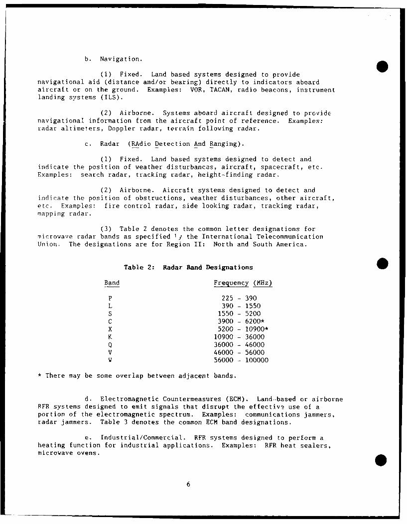
(3) Table 2 denotes the common letter designations formicrowave radar bands as specified 1i the International TelecommunicationUnion. The designations are for Region II: North and South America.
Table 2: Radar Band Designations 0Band Frequency (MHz)
P 225 - 390L 390 - 1550S 1550 - 5200C 3900 - 6200*X 5200 - 10900*K 10900 - 36000Q 36000 - 46000V 46000 - 56000W 56000 - 100000
* There may be some overlap between adjacent bands.
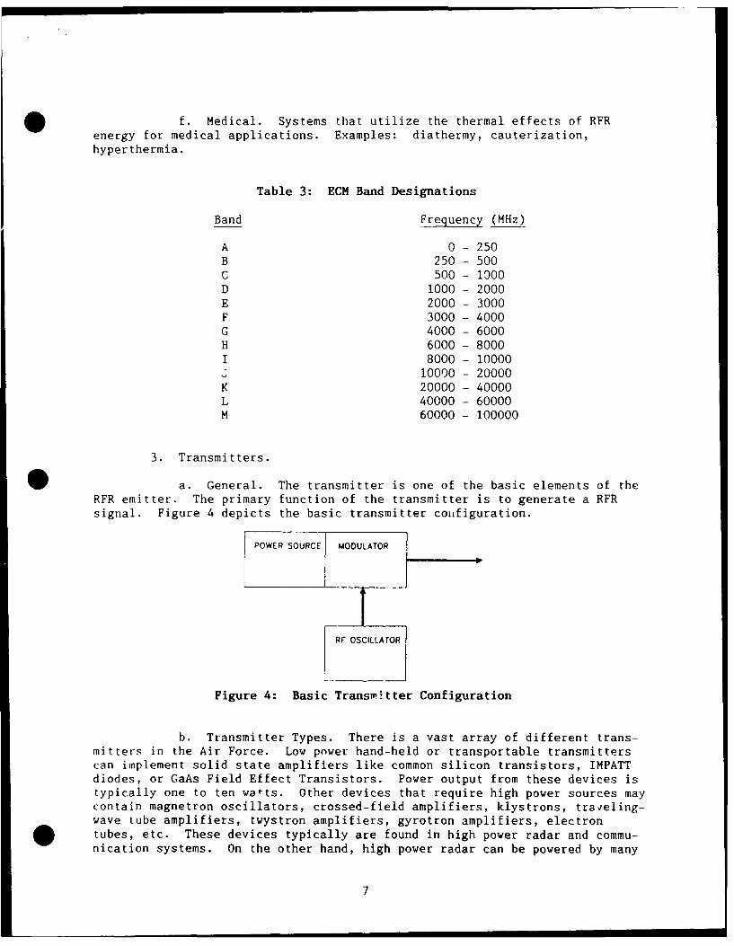
d. Electromagnetic Countermeasures (ECM). Land-based or airborneRFR systems designed to emit signals that disrupt the effective use of aportion of the electromagnetic spectrum. Examples: communications jammers,radar jammers. Table 3 denotes the common ECM band designations.
e. Industrial/Commercial. RFR systems designed to perform aheating function for industrial applications. Examples: RFR heat sealers,microwave ovens.
6
f. Medical. Systems that utilize the thermal effects of RFRenergy for medical applications. Examples: diathermy, cauterization,hyperthermia.
Table 3: ECM Band Designations
Band Frequency (MHz)
A 0 - 250B 250 - 500C 500 - 1000D 1000 - 2000E 2000 - 3000F 3000 - 4000G 4000 - 6000H 6000 - 8000I 8000 - 10000
10000 - 20000
K 20000 - 40000L 40000 - 60000M 60000 - 100000
3. Transmitters.
a. General. The transmitter is one of the basic elements of theRFR emitter. The primary function of the transmitter is to generate a RFRsignal. Figure 4 depicts the basic transmitter configuration.
POWER SOURCE MODULATOR
RF OSCILLATOR
Figure 4: Basic Transmitter Configuration
b. Transmitter Types. There is a vast array of different trans-mitters in the Air Force. Low power hand-held or transportable transmitterscan implement solid state amplifiers like common silicon transistors, IMPATTdiodes, or GaAs Field Effect Transistors. Power output from these devices istypically one to ten watts. Other devices that require high power sources maycontain magnetron oscillators, crossed-field amplifiers, klystrons, traveling-wave tube amplifiers, twystron amplifiers, gyrotron amplifiers, electrontubes, etc. These devices typically are found in high power radar and commu-nication systems. On the other hand, high power radar can be powered by many
7
low power transmitters. The PAVE PAWS phased-array radar 'iscc 3,584transistor modules that individually have a power output of only 440 watts.
c. Transmitter Characteristics. Transmitter specifications canoften be very complex. Often when the BEE or one of his/her techniciansattempt to acquire parameters from system operators, they are overwhelmed by alot of complex and sometimes useless (from the BEE's standpoint!) information.It is your job to weed through this inform3tion and find the usefulinformation. Concerning transmitters, the following parameters are needed:
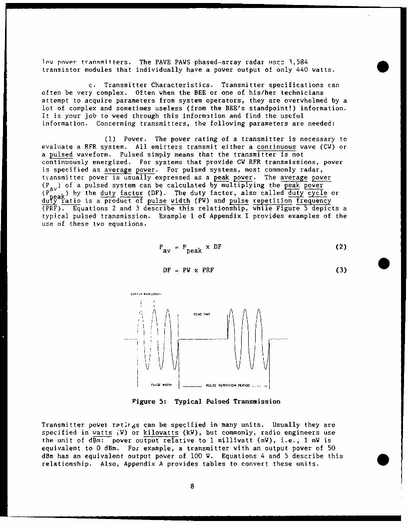
(1) Power. The power rating of a transmitter is necessary toevaluate a RFR system. All emitters transmit either a continuous wave (CW) ora pulsed waveform. Pulsed simply means that the transmitter is notcontinuously energized. For systems that provide CW RFR transmissions, poweris specified as average power. For pulsed systems, most commonly radar,transmitter power is usually expressed as a peak power. The average power(P ) of a pulsed system can be calculated by multiplying the peak power(P a) by the duty factor (DF). The duty factor, also called duty cycle ordu-t ratio is a product of pulse width (PW) and pulse repetition frequency(PRF). Equations 2 and 3 describe this relationship, while Figure 5 depicts atypical pulsed transmission. Example 1 of Appendix I provides examples of theuse of these two equations.
Pav= Ppeak x DF (2)
DF = PW x PRF (3)
C1,44- *:VEtENGIHi
DAD
IE
PTLSE WIDTH __ PULSE R[PfTITION PERIOD
Figure 5: Typical Pulsed Transmission
Transmitter power rotirgs can be specified in many units. Usually they arespecified in watts %W) or kilowatts (kW), but commonly, radio engineers usethe unit of dBm: power output relative to 1 milliwatt (mW), i.e., I mW isequivalent to 0 dBm. For example, a transmitter with an output power of 50dBm has an equivalent output power of 100 W. Equations 4 and 5 describe thisrelationship. Also, Appendix A provides tables to convert these units.
8
O P(dBm) = 10lOglo[P(mW)] (4)
P(mW) = log- IP(dBm)/101 (5)
(2) Frequency. The operating frequency of the transmitter isnecessary to evaluate the RFR emitter. Most systems have their operatingfrequency specified in megahertz (MHz). Some systems operate at a discreetfrequency, while others may operate across a continuous range of frequencies.Still, other emitters may operate at a number of discreet frequencies ordiscreet frequency bands. Confusing the operating frequency of the systemwith the pulse repetition frequency of a pulsed system or the bandwidthspecification is a common error made by people evaluating an emitter. Both ofthese parameters will always be less than the system operating frequency.Determining the range of frequency operation is important in the evaluationand survey of an emitter; for some emitters, especially HF, the PEL andantenna gain can vary drastically across the operating frequency range. Oftenit is necessary to evaluate and measure an emitter at several discreetfrequencies.
(3) Modulation. Modulation is the process where certaincharacteristics of the RFR wave (also called the carrier) are varied inaccordance with the message signal. Modulation can be divided into continuousmodulation where the modulated signal is always present and pulse modulation
O where no signal is present between pulses.
(a) Continuous Modulation. Communications systems likeAM and FM radio, TV, police and fire nets, and CB radios use this type ofmodulated signal. Although there are numerous forms of continuous modulation,we will examine a few of the more common ones.
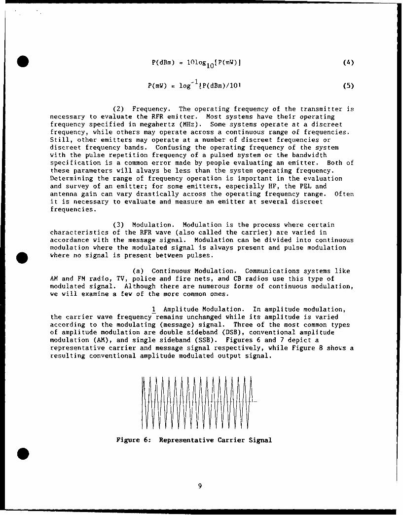
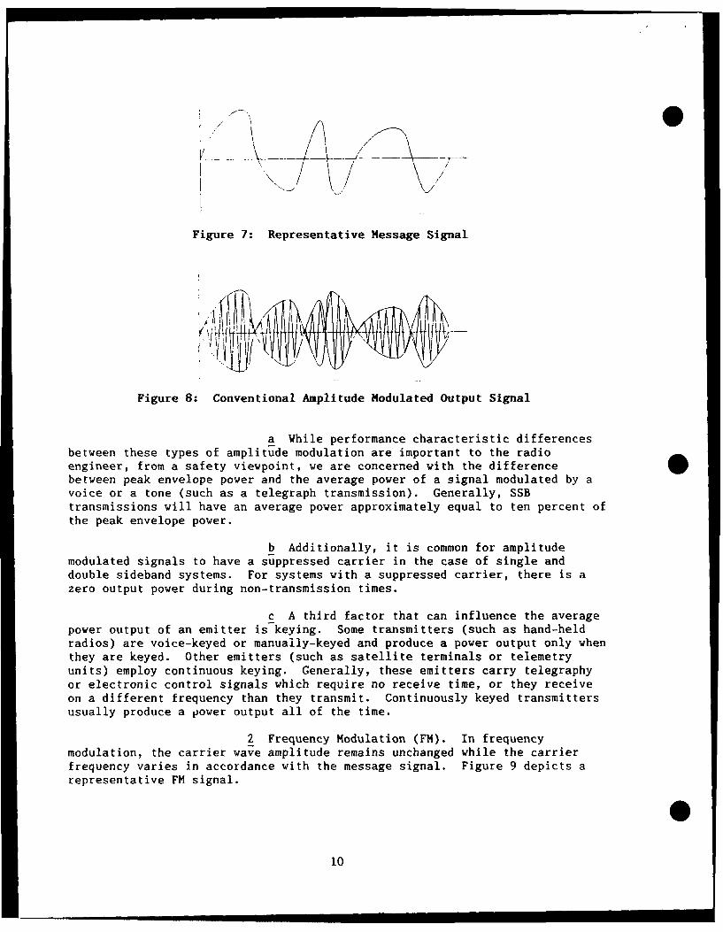
1 Amplitude Modulation. In amplitude modulation,the carrier wave frequency remains unchanged while its amplitude is variedaccording to the modulating (message) signal. Three of the most common typesof amplitude modulation are double sideband (DSB), conventional amplitudemodulation (AM), and single sideband (SSB). Figures 6 and 7 depict arepresentative carrier and message signal respectively, while Figure 8 shows aresulting conventional amplitude modulated output signal.
Figure 6: Representative Carrier Signal
0
• .. =.I~mnuinumnll n ~nmnll • IlR~~l9
I I / ,
/\
Figure 7: Representative Message Signal
Figure 8: Conventional Amplitude Modulated Output Signal
a While performance characteristic differences
between these types of amplitude modulation are important to the radioengineer, from a safety viewpoint, we are concerned with the differencebetween peak envelope power and the average power of a signal modulated by avoice or a tone (such as a telegraph transmission). Generally, SSBtransmissions will have an average power approximately equal to ten percent of
the peak envelope power.
b Additionally, it is common for amplitude
modulated signals to have a suppressed carrier in the case of single anddouble sideband systems. For systems with a suppressed carrier, there is azero output power during non-transmission times.
c A third factor that can influence the average
power output of an emitter is keying. Some transmitters (such as hand-heldradios) are voice-keyed or manually-keyed and produce a power output only whenthey are keyed. Other emitters (such as satellite terminals or telemetryunits) employ continuous keying. Generally, these emitters carry telegraphyor electronic control signals which require no receive time, or they receiveon a different frequency than they transmit. Continuously keyed transmittersusually produce a power output all of the time.
2 Frequency Modulation (FM). In frequencymodulation, the carrier wave amplitude remains unchanged while the carrierfrequency varies in accordance with the message signal. Figure 9 depicts arepresentative FM signal.
10
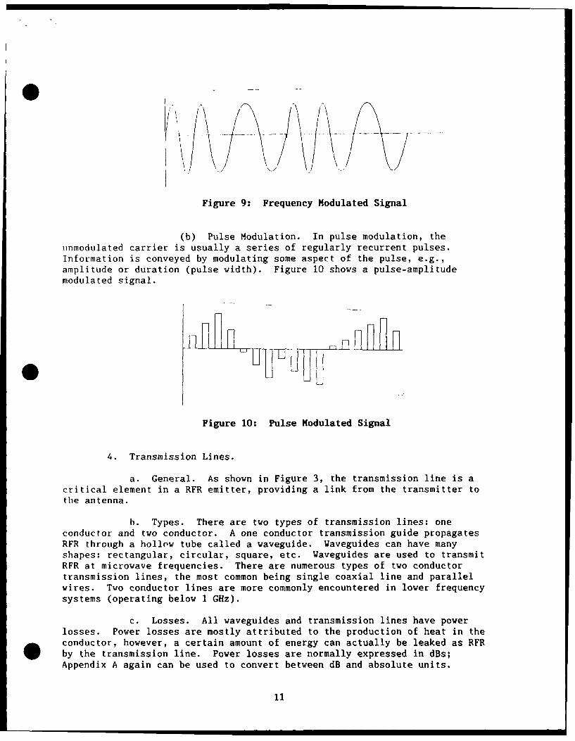
Figure 9: Frequency Modulated Signal
(b) Pulse Modulation. In pulse modulation, theiinmodulated carrier is usually a series of regularly recurrent pulses.Information is conveyed by modulating some aspect of the pulse, e.g.,amplitude or duration (pulse width). Figure 10 shows a pulse-amplitudemodulated signal.
•
Figure 10: Pulse Modulated Signal
4. Transmission Lines.
a. General. As shown in Figure 3, the transmission line is acritical element in a RFR emitter, providing a link from the transmitter tothe antenna.
h. Types. There are two types of transmission lines: oneconductor and two conductor. A one conductor transmission guide propagatesRFR through a hollow tube called a waveguide. Waveguides can have manyshapes: rectangular, circular, square, etc. Waveguides are used to transmitRFR at microwave frequencies. There are numerous types of two conductortransmission lines, the most common being single coaxial line and parallelwires. Two conductor lines are more commonly encountered in lower frequencysystems (operating below 1 GHz).
c. Losses. All waveguides and transmission lines have powerlosses. Power losses are mostly attributed to the production of heat in the
* conductor, however, a certain amount of energy can actually be leaked as RFRby the transmission line. Power losses are normally expressed in dBs;Appendix A again can be used to convert between dB and absolute units.
11
d. Transmission Line Antennas and Their Hazards. As noted above,tLansmision lines propagate RFR like an antenna. In close proximity oftransmission lines RFR hazards can exist. While these hazards are systemunique and dependent on transmitted power, transmission line construction,etc., the phenomena is more common in HF and UHF systems.
e. Leaky or broken waveguides can also propagate RFR like anantenna. There have been a number of overexposure investigations from leakyor broken waveguides. The size of a waveguide break is the most importantfactor in determining its ability to behave as an antenna. For example, ifthe largest dimension of the break is smaller than one-half the systemwavelength, the break will not effectively emit RFR. On the other hand, ifthe break's greatest dimension is greater than one-half the system wavelength,the break could effectively emit RFR. Power densities from a waveguide breakcan be estimated using a horizontal dipole antenna model (See Table 4 of thisreport).
5. Antennas.
a. General. The antcnna is a basic component of any RFR system.The antenna is the connecting link between free space and the transmitter.Its design is largely dependent on the intended use of the system in question.in many systems used for navigation or direction-finding, the operationalcharacteristics of the system are designed around the directive properties ofthe antenna. In other systems, the antenna may be used simply to radiateenergy in all directions to provide broadcast coverage.
b. Antenna Properties. Regardless of the systems application allantennas have basic properties that can be well defined. Of these, gain,size, accessibility, and radiation pattern are of principle interest inevaluating radiation hazards.
(1) Gain.
(a) The gain or directivity of an antenna is the measureof its ability to concentrate its energy in a certain direction. Directivityis closely related to the radiation pattern of an antenna. To understandantenna gain, first, picture an isotropic emitter: a hypothetical RFR sourcethat radiates evenly in all directions from a point in space. Figure 11 showsan isotropic emitter.
012
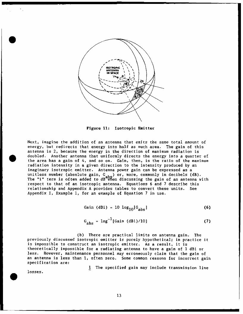
Figure 11: Isotropic Emitter
Next, imagine the addition of an antenna that emits the same total amount ofenergy, but redirects that energy into half as much area. The gain of thisantenna is 2, because the energy in the direction of maximum radiation is
* doubled. Another antenna that uniformly directs the energy into a quarter ofthe area has a gain of 4, and so on. Gain, then, is the ratio of the maximumradiation intensity in a given direction to the intensity produced by animaginary isotropic emitter. Antenna power gain can be expressed as aunitless number (absolute gain, G ) or, more, commonly in decibels (dB).The "i l term is often added to dB men discussing the gain of an antenna withrespect to that of an isotropic antenna. Equations 6 and 7 describe thisrelationship and Appendix A provides tables to convert these units. SeeAppendix I, Example 1, for an example of Equation 7 in use.
Gain (dBi) = 10 loglO[Gabs] (6)
Gabs = log- [Gain (dBi)/10 (7)
(b) There are practical limits on antenna gain. Thepreviously discussed isotropic emitter is purely hypothetical; in practice itis impossible to construct an isotropic emitter. As a result, it istheoretically impossible for a radiating antenna to have a gain of 1 dBi orless. However, maintenance personnel may erroneously claim that the gain ofan antenna is less than 1, often zero. Some common reasons for incorrect gainspecification are:
1 The specified gain may include transmission linelosses.
13
2 Maintenance personnel may be confusing antennagain (power density gain resulting from spatial concentration of energy, indBi) with electronic gain (power gain created by electronic amplifiers, indB).
3 The emitter may be dummy loaded, in which casethe antenna gain is undefined, but may be specified as zero.
Practically, the range of antenna gains is from 2.0 dBi for a dipole, to 70dBi for a pencil beam aperture antenna.
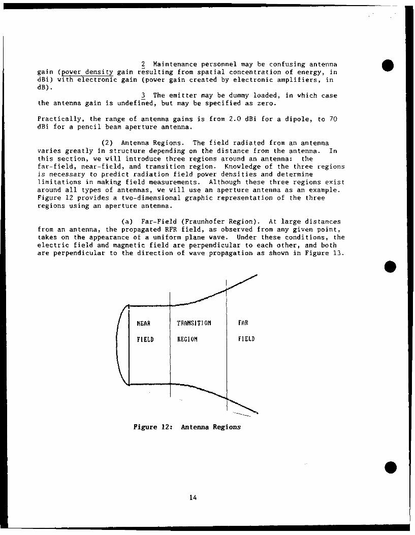
(2) Antenna Regions. The field radiated from an antennavaries greatly in structure depending on the distance from the antenna. Inthis section, we will introduce three regions around an antenna: thefar-field, near-field, and transition region. Knowledge of the three regionsis necessary to predict radiation field power densities and determinelimitations in making field measurements. Although these three regions existaround all types of antennas, we will use an aperture antenna as an example.Figure 12 provides a two-dimensional graphic representation of the threeregions using an aperture antenna.
(a) Far-Field (Fraunhofer Region). At large distancesfrom an antenna, the propagated RFR field, as observed from any given point,takes on the appearance of a uniform plane wave. Under these conditions, theelectric field and magnetic field are perpendicular to each other, and bothare perpendicular to the direction of wave propagation as shown in Figure 13.
NEAR TRANSITION FAR
FIELD REGION FIELD
Figure 12: Antenna Regions
14
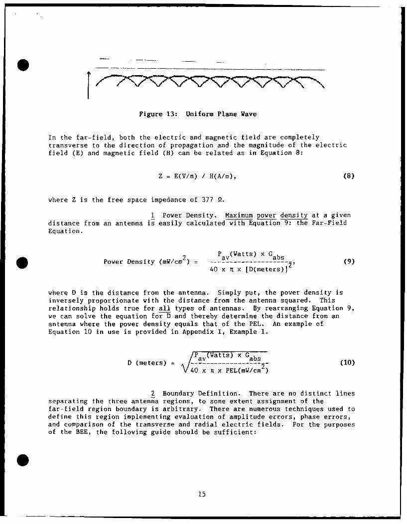
Figure 13: Uniform Plane Wave
In the far-field, both the electric and magnetic field are completelytransverse to the direction of propagation and the magnitude of the electricfield (E) and magnetic field (H) can be related as in Equation 8:
Z = E(V/m) / H(A/m), (8)
where Z is the free space impedance of 377 9.
1 Power Density. Maximum power density at a givendistance from an antenna is easily calculated with Equation 9: the Far-FieldEquation.
2 P av (Watts) x GabsPower Density (mW/cm) = --------------- (9)
40 x n x [D(meters)]
where D is the distance from the antenna. Simply put, the power density isinversely proportionate with the distance from the antenna squared. Thisrelationship holds true for all types of antennas. By rearranging Equation 9,we can solve the equation for D and thereby determine the distance from anantenna where the power density equals that of the PEL. An example ofEquation 10 in use is provided in Appendix I, Example 1.
P a(Watts) x GD (meters) .av abs (10)
V40 x - x PEL(mW/cm 2 )
2 Boundary Definition. There are no distinct linesseparating the three antenna regions, to some extent assignment of thefar-field region boundary is arbitrary. There are numerous techniques used todefine this region implementing evaluation of amplitude errors, phase errors,and comparison of the transverse and radial electric fields. For the purposesof the BEE, the following guide should be sufficient:
0
15
For:(f > 300 MHz): Far-Field > 12 x L2 ]/X (11)
(300 MHz > f > 30 MHz): Far-Field > 5 x L (12)
(30 MHz > f): Far-Field > 1.6 x X, (13)
where L is the longest dimension of the antenna and X is signal wavelength.Note that for the three equations given there is not a specified unit forantenna length, L, or signal wavelength, X; any unit can be used provided thatthe same units are used for both parameters. See Example 1 of Appendix I foran example of Equation 11 in use.
(b) Near-Field (Fresnel Region). At close distances toan antenna, the field does not decrease with distance as is the case in thefar-field; instead, it remains relatively constant. In the near-field, theelectric and magnetic fields are not completely transverse to the direction ofRF propagation, the two fields do not approximate a uniform plane wave, andthe two fields cannot be related to each other by free space impedance of377 Q. In the near-field of an antenna, both the magnetic and electricradiation fields are complex as compared to that of the far-field. Forexample, in the near-field of dipoles, impedance is very high as compared tothe far-field impedance of 377 2; in this case, the magnetic field is small iwith respect to the tangential electric field, as compared to theirrelationship in the far-field.
1 Power Density. Unfortunately, calculations todetermine power densities in the near-field are not as simple as in the caseof the far-field. For aperture antennas, like the one in Figure 16, andcharacteristic of most antennas operating at or above 300 MHz, we suggestusing Equation 14 to estimate the maximum power density on the main beam axis.Example 2 of Appendix I illustrates the use of this equation. Additionally,T.O. 31Z-10-4 contains correction factors for determining power density valuesin the near-field of an emitter.
Power Density = (4 x P av)/(Antenna Area) (14)
For dipole, monopole, and similar antennas as described in Appendix H, wesuggest using Tables 4 and 5 to estimate power density levels. To use thetable, simply match the input power to the antenna in the left column and thePEL in the top row. These antennas normally operate below 300 MHz.
016
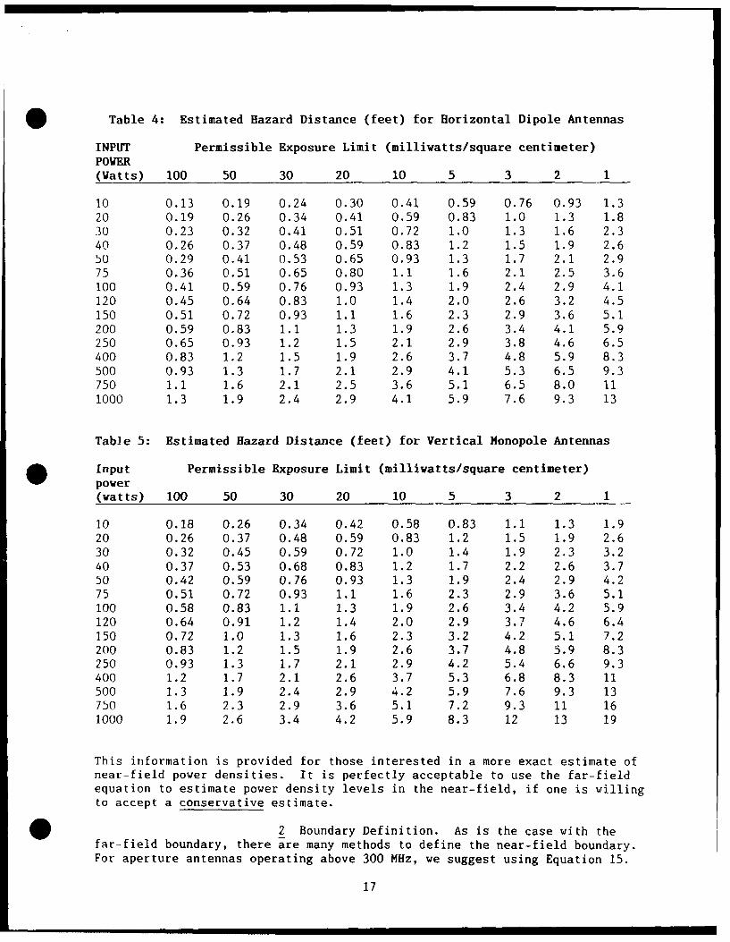
Table 4: Estimated Hazard Distance (feet) for Horizontal Dipole Antennas
INPUT Permissible Exposure Limit (millivatts/square centimeter)POWER(Watts) 100 50 30 20 10 5 3 2 1
10 0.13 0.19 0.24 0.30 0.41 0.59 0.76 0.93 1.320 0.19 0.26 0.34 0.41 0.59 0.83 1.0 1.3 1.830 0.23 0.32 0.41 0.51 0.72 1.0 1.3 1.6 2.340 0.26 0.37 0.48 0.59 0.83 1.2 1.5 1.9 2.650 0.29 0.41 0.53 0.65 0.93 1.3 1.7 2.1 2.975 0.36 0.51 0.65 0.80 1.1 1.6 2.1 2.5 3.6100 0.41 0.59 0.76 0.93 1.3 1.9 2.4 2.9 4.1120 0.45 0.64 0.83 1.0 1.4 2.0 2.6 3.2 4.5150 0.51 0.72 0.93 1.1 1.6 2.3 2.9 3.6 5.1200 0.59 0.83 i.1 1.3 1.9 2.6 3.4 4.1 5.9250 0.65 0.93 1.2 1.5 2.1 2.9 3.8 4.6 6.5400 0.83 1.2 1.5 1.9 2.6 3.7 4.8 5.9 8.3500 0.93 1.3 1.7 2.1 2.9 4.1 5.3 6.5 9.3750 1.1 1.6 2.1 2.5 3.6 5.1 6.5 8.0 111000 1.3 1.9 2.4 2.9 4.1 5.9 7.6 9.3 13
Table 5: Estimated Hazard Distance (feet) for Vertical Honopole Antennas
Input Permissible Exposure Limit (milliwatts/square centimeter)power(watts) 100 50 30 20 10 5 3 2 1
10 0.18 0.26 0.34 0.42 0.58 0.83 1.1 1.3 1.920 0.26 0.37 0.48 0.59 0.83 1.2 1.5 1.9 2.630 0.32 0.45 0.59 0.72 1.0 1.4 1.9 2.3 3.240 0.37 0.53 0.68 0.83 1.2 1.7 2.2 2.6 3.750 0.42 0.59 0.76 0.93 1.3 1.9 2.4 2.9 4.275 0.51 0.72 0.93 1.1 1.6 2.3 2.9 3.6 5.1100 0.58 0.83 1.1 1.3 1.9 2.6 3.4 4.2 5.9120 0.64 0.91 1.2 1.4 2.0 2.9 3.7 4.6 6.4150 0.72 1.0 1.3 1.6 2.3 3.2 4.2 5.1 7.2200 0.83 1.2 1.5 1.9 2.6 3.7 4.8 5.9 8.3250 0.93 1.3 1.7 2.1 2.9 4.2 5.4 6.6 9.3400 1.2 1.7 2.1 2.6 3.7 5.3 6.8 8.3 11500 1.3 1.9 2.4 2.9 4.2 5.9 7.6 9.3 13750 1.6 2.3 2.9 3.6 5.1 7.2 9.3 11 161000 1.9 2.6 3.4 4.2 5.9 8.3 12 13 19
This information is provided for those interested in a more exact estimate ofnear-field power densities. It is perfectly acceptable to use the far-fieldequation to estimate power density levels in the near-field, if one is willingto accept a conservative estimate.
2 Boundary Definition. As is the case with thefar-field boundary, there are many methods to define the near-field boundary.For aperture antennas operating above 300 MHz, we suggest using Equation 15.
17
For dipole, monopole, and similar antenna that normally operate below 300 MHz,
we suggest using Equation 16. For:
(f > 300 MHz): Near-Field < L2 /14 x X) (15)
(f < 300 MHz): Near-Field < X, (16)
where L is the longest dimension of the antenna and X is signal wavelength.An illustration of the use of Equation 15 is provided in Example 1 ofAppendix I.
(c) Transition Region. The transition zone containscharacteristics of both the far-field and near-field. Generally, the electricand magnetic field are somewhat transverse to the direction of propagation andtherefore, they are approximately related by free space impedance of 377 9.Additionally, power density does decrease with distance from the antenna, butits level cannot be accurately predicted with the far-field equation.
(d) Field Measurements. The most practical use ofunderstanding antenna regions is its application to performing measurementsurveys. Generally, when performing measurements in the near-field it isnecessary to measure both the electric and magnetic field components toascertain accurate information about the field. Practically, this should bedone for emitters that radiate below 100 MHz, while surveying in thenear-field. For measurements in the far-field and usually the transitionregion, the electric and magnetic field are related by free space impedance of377 2 and there is no need to measure both fields. It is likely that the nextrevision to AFOSH Standard 161-9 will incorporate separate magnetic andelectric field standards for systems that emit below 100 MHz, where theequivalent far-field power density values are different.
(3) Radiation Pattern.
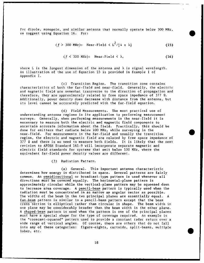
(a) General. This important antenna characteristicdetermines how energy is distributed in space. Several patterns are fairlycommon. An omnidirectional or broadcast-type pattern is used whenever alldirections must be covered equally. The horizontal-plane pattern isapproximately circular while the vertical-plane pattern may be squeezed downto increase area coverage. A pencil-beam pattern is typically used when theradiation must be concentrated in as narrow an angular sector as possible.The widths of the beam in the two principal planes are essentially equal. Afan-beam pattern is similar to a pencil-beam pattern except that the beamcross section is elliptical rather than circular in shape. The beam width inone plane may be considerably broader than the beam width in the other plane.A shaped-beam pattern is used when the pattern in one of the principal planesmust have a special shape for the type of coverage required. An example isthe "cosecant-squared" pattern used to provide a constant radar return over awide range of vertical angles. Of course, there are others that do not fallinto any of these categories: figure-eights, cartoids, split-beams, multiplelobes, etc.
18
(b) Beam Width. The important characteristics of simpleantenna patterns (fan, pencil, shaped, etc.) can be specified in terms of thebeam width in the two principal planes: horizontal and vertical. The beamwidth of a radiation pattern is the angular width of the beam defined by thepoints where power is one half of maximum beam power. Beam width is acharacteristic more commonly associated with aperture antennas; however, itcan be defined for omnidirectional antennas as well. Antenna beam width isclosely related to antenna gain. Naturally, antennas with large gains willhave small beam widths, and conversely, antennas with small gains will havelarge beam widths. Normally, beam widths are specified in the horizontal andvertical planes for rectangular aperture antennas and wire antennas. A singlecircular width is given for circular apertures. Beam width is typicallyspecified in degrees.
(c) Beam pattern shape, gain, typical beam widths, andpictorial examples for common antennas are given in Appendix H.
IV. THE HAZARDS
A. Classification of Hazards.
1. RFR energy can be a hazard in more than one way. The usualclassifications are as follows:
* a. Direct biological (personnel) hazards due to absorptionof RFR energy and the subsequent heating of body tissues.
b. Indirect biological hazard due to interference withelectronic medical prosthetic devices like cardiac pacemakers and otherbiomedical equipment.
c. Indirect hazard due to ignition of petroleum, oil, andlubricants (POL) or the detonation of electro-explosive devices (EEDs).
2. Each of these categories is linked to a different safetystandard or criterion. BES has no responsibility for dealing with theindirect hazards, but one can profit by becoming familiar with them andknowing how to contact the corresponding referral agencies. Let'sexamine each type of hazard.
a. Direct Biological. RFR energy at sufficiently highlevels causes heating in body tissues. The amount of RFR energy that isabsorbed and converted to molecular energy is strongly frequencydependent. In general, with regard to human beings, it can be said thatthe longer the wavelength the greater the depth of penetration.Wavelengths of 3 cm or less (10 GHz or higher) are absorbed by the skin.Depth of penetration is only one factor; energy deposited is the keyissue. In general, the greatest absorption in adult humans takes placeat 70 to 80 MHz if they are not electrically grounded, and 30 to 40 MHzif they are. The mechanism for transfer of energy to the human body byRFR is by friction resulting from the vibration/rotation of the body'spolar molecules (mainly water) within the viscous cell medium. Butwhatever the frequency, an RFR induced burden adds to other thermal
19
burdens and produces normal physiological adjustments like sweating andvasodilation. If biological or environmental factors prevent theeffective dissipation of heat, the exposed tissue will be heated andpossibly damaged. The effects of this type of exposure are notconsidered to be cumulative as they are with ionizing radiation.Exposures separated by more than a few minutes (six, by the standard)are essentially separate physiological events.
b. Indirect Biological Hazard. AFOSH Standard 161-9 isclear on cardiac pacemaker hazards. Extensive tests have beenconducted, and most manufacturers have voluntarily produce devices thatare unaffected by RFR fields below 200 V/m (about 10 mW/cm ). Very highpower Air Force systems can produce levels in areas that are high enoughto interfere with today's pacemakers. These areas should already havecontrol measures in place to preclude access to the direct per-:onnelhazards and therefore, there is no need to post signs for the expresspurpose of warning pacemaker wearers.
c. POL Hazard. RFR energy will produce an arc under theright conditions and cause the 2ignition of flammable vapors. The safetystandard for POL is 5 watts/cm , based on peak power. Any locationwhere flammable vapors could be released, like the transfer of fuel fromone tank to another, is suspect. T.O. 31Z-10-4 provides moreinformation on this topic, or contact 1842 EEG/EEITE, Scott AFB IL62225, AUTOVON 576-5596 for assistance in POL hazards.
d. Electro-Explosive Device (EED) Hazard. EEDs (alsocalled squibs) are associated with many aircraft weapon systems.Basically, they are small explosive devices that are detonated by anelectric current, often in order to detonate larger explosive devices.Many different hazard levels are defined in AFM 127-100, depending onthe configuration of the EEDs in question. Concerned organizationsshould contact the weapons safety office on base. If they cannot solvetheir problem they should then contact ASD/ENACE, Wright-Patterson AFBOH 45433-6503, AUTOVON 785-7275.
e. X-ray Emissions. Radar units contain klystron,magnetron, and thyratron tubes that emit ionizing radiation as a resultof high voltage being applied to the tube. Radar units also haveinterlock systems in the area where the high voltage is located;however, many times the interlocks are bypassed by maintenance personnelduring testing. For this reason it is important to insure thatmaintenance personnel are not being overexposed to ionizing radiationwhen cabinet doors are open. Another consideration to be made duringsurvey of x-ray emissions is that an RF-shielded survey instrument isused. A Victoreei Model 440 will not give accurate readings, the 440RFmodel should be used instead. To perform a survey, measurements aretaken on all sides of the transmitter cabinet, especially around sealsto removable panels. If possible, remove panels that are removedroutinely and check for leakage. Caution should be observed whenmeasuring x-ray emissions with panels removed because of the potentialfor high voltage arcing. It is good practice not to advance the meterbeyond the limits of the cabinet frame. X-ray levels should not exceed2 mR/hour. For more information on this topic, please consult USAFOEHL
20
Fpporr 85-144RII11HXA, "Ionizing Radiation Guidebook forBioenvironmental Engineers (BEEs)."
B. Thermal vs Athermal.
1. An important point to note when talking to people about RFRprotection is that biological effects are not necessarily biologicalhazards. Research communities thro7-ghout the world continue to publishpaper after paper on the biological effects of RFR. Scientists inEastern Europe and Russia have reported long lists of symptoms(decreased blood pressure, feelings of apathy and depression, etc.) atlevels of exposure that are well below the USAF PEL. Even thoughefforts in the Western worle to replicate these results have failed, wecannot totally ignore them. The fact is, we just don't know all thereis to know about the effects of RFR on the human organism.
2. The current USAF standard for RFR protection, given in AFOSHStandard 161-9, is designed to protect us from the known thermal hazardsassociated with RFR emissions. The PELs have been shown to present aninsignificant thermal load to the body. We do not ignore thepossibility of "atnermal" (not related to heating) effects, but it iscurrent USAF policy to classify low-level athermal effects as beingnonhazardous.
C. Managing Misconceptions.
* 1. There are some not-so-unusual ideas floating around the AirForce about RFR. Unfortunately, these misconceptions can be dangerous.There are still supporters of the "if you can't see it, it can't hurtyou" theory. People with the opposite viewpoint, weave fantastic talesabout the killing of mice at ridiculously low power density levels.Both types of people can make our jobs harder.
2. Education is the best way to effectively manage theseproblems. Take the time to educate RFR workers on your base.
D. Electromagnetic Interference.
1. With the multitude of RFR emitters and other electronicequipment located on the typical Air Force installation, it is common tofind many cases of electromagnetic interference. Nonhealth hazards likeelectromagnetic interference are reported IAW AFR 700-13. Though BES isnot responsible for the control of electromagnetic interference,unfortunately they are often consulted about these problems. Asconsultants, we have had the opportunity to hear a wst array of storiesconcerning electromagnetic interference over the years. Stories ofvideo display terminals losing characters, periodic interference to anAM broadcast signal, and poor FM television reception are some of thecommon ones. Periodically, some of the stories are more bizarre, likevending machines spuriously dropping change, yarning lights onautomobiles sporadically illuminating while in the vicinity of groundbased search radar, and electronic typewriters typing without anoperator. In the vast majority of RFR interference cases, there are no
21
personnel hazards, but, people often associate electromagneticinterference with the potential for personnel hazards.
2. Electronic equipment, such as televisions and video displayterminals (VDTs), responds to two types of interference, conductedinterference and radiated interference. Since we are concerned withradiation protection, we will discuss radiated interference. Mostinterference to digital equipment such as VDTs is caused by radar,because radar usually employs transmissions with high peak power andlarge bandwidth. When an electric field acts on a piece of digitalequipment it can alter the logic state of individual devices, therebycausing spurious errors. It is important to understand that theseerrors are caused by peak field intensity rather than average fieldintensity, and therefore, radars with high peak powers and low dutyfactors can cause interference without being a health hazard, since theaverage power associated with these phenomenon are usually very low.For example, a typical VDT has an interference susceptibility thresholdof 8 to 133 volts/Teter (peak) or equivalent power density leveAs of0.017 to 4.8 mW/cm . If the radar had a duty factor of 1 x 10- theaverage power density levels would be 0.017 to 4.8 microwatts/cm , wellbelow all PELs for RFR.
3. FM television interference can be caused by many types ofRFR signal, pulsed or continuous wave. This occurs when an interferingsignal modulates the broadcast signal and then causes changes in thetelevision picture. For the television signal to be considered"interference free" it needs to be 15 dB above any interfering signal.A typical television receiver sensitivity is approximately -93 dBm, soan interfering signal only has to be -108 dBm to cause picture 1014distortion. Ihis corresponds to a power density level of 1.5 x 10milliwatts/cm ! In fact, this level is so low that a vacuum cleaner caneasily cause interference to a television.
4. RFR average power density levels in the microwatt/cm2 rangecan easily cause interference with common electronic equipmenbut, interference phenomena are rarely associated with a healti h....:d.
V. STANDARDS
A. The Basis of Our Permissible Exposure Limits (PELs).
1. What level of RFR is safe? It's a big question, and a lot ofpeople, educated or not, have made stabs at an answer. Many not-so-qualifiedwriters have implied in their books and articles that there is no scientificbasis for the current PEL. It is not uncommon to find government and industryaccused of a massive cover-up of the "real" hazaids associated with RFR. Manysay that because the Soviet "standard" is lower than ours, we are eitherfoolish or ignorant.
2. Not necessarily true. There have been volumes of paper generatedover the past 35 years on subjects related to RFR biological effects. Thenumber of papers published is in the thousands, and the research continues.National and international information exchanges have been held every year
22
O since 1973. Millions of dollars have been spent in research facilitiesdevoted to understanding the nature of biological responses to RFR.
3. In 1958 DoD adopted its 5irst standard for exposures to RFR. Thefirst standard set a PEL o5 50 mW/cm for frequencies between 10 kHz and 10MHz, and a PEL of 10 mW/cm for frequencies between 10 MHz and 300 GHz. Thestandard was based on exposures averaged over any six-minute period of time.The 10 mW/cm PEL originated from physiological onsideration that whole-bodyexposure to humans to a level of about 100 mW/cm or more would cause a mild-to-severe increase in thermal load (depending on the load), and by applicationof a safety factor of 10. This guide was bised on a belief that nearly allworkers could be exposed to RFR at 10 mW/cm or lower during a normal seriesof working days without adverse effects. Adoption of this guide alsorecognized that electromagnetic fields at or below the PEL could causephysiological effects, but the effects had no adverse medical consequences.
4. Since the first standard was introduced, there has beenconsiderable research to indicate that the human body selectively absorbs RFRdependent on frequency. In 1982, the American National Standards Institute(ANSI) developed a frequency dependent standard. The standard is based onobserved thermal effects from a mean whole-body specific-absorption rate (SAR)of 4 W/kg; with a safety factor of 10, the standard is 0.4 W/Kg. The SAR is ameasure of the absorbed energy from an incident electromagnetic field and isnormally expressed as energy absorbed per un t volume (watts/kilogram), where1 kilogram is equal to approximately 1000 cm (for most biological systems).
* The standard also contains a partial body limit, spacial peak SAR, that isbased on 8 W/kg averaged over any one gram of tissue.
5. The localized value of SAR within a given entity is dependent onfrequency, modulation, amplitude and polarization of an incident RFR field;the properties of the material; and the configuration of the material withrespect to the incident field. For entities that are complex in shape andvariant in distribution of its constituents, distribution of local SAR isdifficult to determine. As a result, the concept of whole-body SAR wasdeveloped, because this quantity is easy to measure experimentally without theneed to understand the SAR internal distribution.
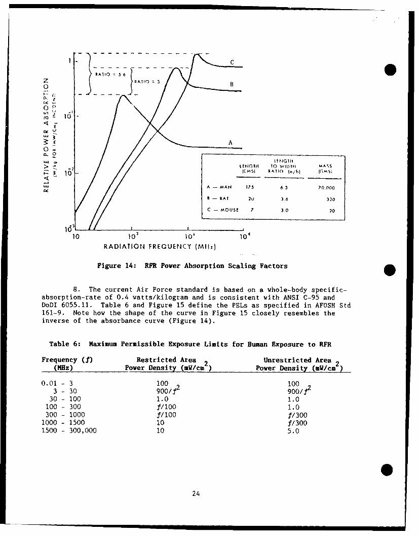
6. The whole-body SAR is highly dependent on the size of the body.Figure 14 demonstrates this phenomenon by comparison of the RFR absorption ofthree different size bodies: a man, a rat, and a mouse. The peak absorbanceof a mouse (at - 1050 MHz) is 5.6 times that of man (at - 70 MHz).
7. Note also from Figure 14, how RFR absorption for man varies withfrequency. At 10 MHz and below, the human body is transparent to RFR,absorbing very little as compared to the frequencies near 70 MHz. While forfrequencies above 1000 MHz, the absorbance factor is rather constant.
23
NA110 :5 6
z RAT1O 3 B0z
00
N A0-10
CL 0
> - 7 LENGTH 10 WIII)II MA S
'-" 10 ICMSI RA1IO (n/bI j(MSI
U A - MAN 175 6.3 70.000
- RAT 20 36 320
C - MOUSE 7 3.0 20
10 10 101 10RADIATION FREQUENCY (M11z)
Figure 14: RFR Pover Absorption Scaling Factors
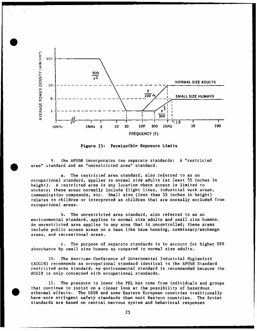
8. The current Air Force standard is based on a whole-body specific-absorption-rate of 0.4 watts/kilogram and is consistent with ANSI C-95 andDoDI 6055.11. Table 6 and Figure 15 define the PELs as specified in AFOSH Std161-9. Note how the shape of the curve in Figure 15 closely resembles theinverse of the absorbance curve (Figure 14).
Table 6: Maximum Permissible Exposure Limits for Human Exposure to RFR
Frequency (f) Restricted Area 2 Unrestricted Area 2(MHz) Pover Density (mV/cm-) Power Density (mV/cm)
0.01 - 3 100 1003 - 30 900/f2 9001f2
30 - 100 1.0 1.0100 - 300 ,f/0 1.0300 - 1000 f1100 f1300
1000 - 1500 10 f/3001500 - 300,000 10 5.0
24
E
E
>-900V)F 2
zNORMAL SIZE ADULTS
WFo1 5- SMALL SIZE HUMANS
w II
I I I
1OkHz IMHz 3 10 30 100 300 1GHz 10 100
FREQUENCY (F)
Figure 15: Permissible Exposure Limits
9. [he AFOSH incorporates two separate standards: A "restrictedO area" standard and an "unrestricted area" standard.
a. The restricted area standard, also referred to as anoccupational standard, applies to normal size adults (at least 55 inches inheight). A restricted area is any location where access is limited toworkers; these areas normally include flight lines, industrial work areas,communication compounds, etc. Small size (less than 55 inches in height)relates to children or interpreted as children that are normally excluded fromoccupational areas.
b. The unrestricted area standard, also referred to as anenvironmental standard, applies to normal size adults and small size humans.An unrestricted area applies to any area that is uncontrolled; these areasinclude public access areas on a base like base housing, commissary/exchangeareas, and recreational areas.
c. The purpose of separate standards is to account for higher RFRabsorbance by small size humans as compared to normal size adults.
10. The American Conference of Governmental Industrial Hygienists(ACGIH) recommends an occupational standard identical to the AFOSH Standardrestricted area standard; no environmental standard is recommended because theACGIH is only concerned with occupational standards.
11. The pressure to lower the PEL has come from individuals and groups* that continue to insist on a closer look at the possibility of hazardous
athermal effects. The USSR and some Eastern European countries traditionallyhave more stringent safety standards than most Western countries. The Sovietstandards are based on central nervous system and behavioral responses
25
attributed to RFR exposure in animals. In Western countries, the standardsare based primarily on calculated thermal burden, because Western scientists 0have not been able to reproduce Soviet experimental results.
B. By the Standard.
1. The USAF PEL for RFR has two criteria:
a. The first is the power density level criteria. It isapplicable in developing theoretical or measured hazard profiles around RFRemitters assuming indefinite exposure durations (greater than 6 minutes).
b. The second is a time-dependent criterion used primarily inoverexposure determinations and when evaluating rotating or pulsed radars andportable communication devices.
2. The standard is relatively simple to apply. Match the operatingfrequency of the device to the standard; if a particular device can operateacross a range of frequencies, the lowest PEL for the range of frequencieswould apply. The PELs apply to all personnel. No additional restrictions arenecessary for female RFR workers, even when pregnant.
3. The standard defines a single PEL for both the magnetic andelectric field. For far-field conditions where free-space impedance is equalto 377 2, the electric arid magnetic fields are related by free-space impedanceand one would expect that both the measured electric and magnetic fields wouldresult in equivalent power density values. However, in the near-field of anemitter this is not always the case; in fact, it is very common for the valuesto differ considerably. The "worst case" measured value of the electric ormagnetic field is compared to the standard when both measurements are made.The most stringent case is what your control measures are based on.
C. Have I Been Zapped?
1. Sometimes there is confusion about application of the exposurecriteria when overexposure determinations are being made2 Total exposure canbe quantified as either the average power density (mW/cm ) over a given6 minute period of time or t~e integrated exposure for a 6 minute period oftime quantified in mW-sec/cm .
2. Under the latter method, a person is considered to have beenoverexposed if, during any 6 minute period, the total ccumulated exposureexceegs the value of 360 times the PEL (3600 mW-sec/cm for a PEL of 10mW/cm ).
3. Remember, overexposure determinations are based on average powerover time. Intermittent exposures, like those from a scanning radar, must becalculated by multiplication of the fixed-beam power density with anadditional scanning duty factor. The scanning duty factor is easy tocalculate: simply divide the beam width (in the plane of scanning) by thetotal scanned sector size. For example, the scanning duty factor is 0.0083for a radar that scans horizontally 3600 and has a horizontal beam width of30.2
26
* D. Future Standards.
1. Currently, there is no Federal Law for control of RFR exposures tothe general public. In the past, the Environmental Protection Agency (EPA)proposed three potential environmental standards. The most stringent proposalwould set the standard at one-tenth the present Air Force standard.Implementation of a new standard in the near future seems unlikely because theEPP decided a standard was not needed at this time.
2. In June 1988, the American National Standards Committee C-95 onRadio Frequency Radiation Hazards met and considered changes to the ANSIStandard. If a new standard is adopted it is likely that the AFOSH Standardwill follow suit. The two most notable proposed changes are listed below:
a. Separate electric and magnetic field standards for frequenciesless than 300 MHz. The electric field standard will remain the same, whilethe standard for the magnetic field will be increased.
b. Reduced time-averaging period for frequencies greater than10 GHz. The averaging period will gradually decrease as frequency increases.
3. The DoD has a tri-service working group developing a standard forhigh power microwave (HPM) and electromagnetic pulse technology applications.The standard, if developed, will define higher exposure limits for shortexposure durations typical of these technologies. It is likely that the nextrevision of AFOSH Standard 161-9 will implement a new standard.
VI. BASE PROGRAM
A. Getting Started.
1. AFOSH Standard 161-9. Familiarity with the responsibilities setforth in the AFOSH Standard is an important first step.
2. Unit Radiation Protection Officers (RPOs). A valuable asset toBES and EHS is a unit RPO. Unit RPOs can assist in identifying emitters intheir organization, assist in interfacing with workplace supervisors andpersonnel, help sell and promote your program and any safety requirements, andnotify BES of important changes that affect safety requirements. RPOs canalso help promote awareness and understanding of RFR to personnel andinitially reduce tensions if a suspected overexposure to RFR is claimed. Werecommend using the RPO in all unit RFR matters. If units do not have an RPO,we suggest tasking the unit commander to appoint one. AFOSH Std 161-9requires commanders to do this. In the tasking, it is important to point outthat the position is not just a figure-head; depending on the unit, theposition may require a great deal of time and should require of the individualmore than just a lay person's understanding of RFR.
0
27
B. Inventory.
1. General. One of the most time consuming tasks in setting up agood RFR protection program is compiling an inventory of all emitters on base.It is absolutely essential. Take a minute to review page 7 of AFOSH Standard161-9 where it talks about inventories.
2. Case File Documentation. A copy of the standardized RFR inventoryform, AF Form 2759 is included in Appendix B, along with instructions forfilling it out, as specified in AFOSH Standard 161-17. This form, properlycompleted, makes a handy reference for quick answers to RFR questions.Getting the information to fill in the blanks on the form is not trivial, butdo the best you can. If you are just starting your inventory, call the basefrequency manager (usually at the base communications squadron). Thisindividual has a listing of all the frequencies authorized for use on the base(airborne emitters excepted) and may know who to contact for furtherinformation on each. T.O.s for aircraft usually contain operating parametersfor airborne emitters. Another source is the Electromagnetic CompatibilityAnalysis Center (ECAC/ACZ, North Severn, Annapolis MD 21402, AUTOVON281-2681). They can provide detailed computer listings of equipmentparameters and locations. Still another source is AFOEHL--call us if you needparticular information on a system at your base. It is unlikely that one
source will give you all the information you need; some of the information isavailable only through persistence. We suggest that you make a form letterrequesting the necessary information, and send it to every candidateorganization on base, negative replies required. This doesn't always resultin complete accuracy, but it does spread the word around.
3. Central Inventory. A central inventory of all emitters on base isrequired by AFOSH Std 161-9, para C4a(1). Also, the Inspector Generalnormally reviews the inventory because it provides an overall view of your RFRprotection program. Beyond these reasons, the central inventory is amanagement tool that will help you as the base RPO keep track of all thehazardous emitters on base, pending items like suspensed items to unit RPOs,etc. We recommend the following items for the central inventory:
a. A summary list of emitters and their hazard distance, hazard
code, and location on base.
b. List of the unit RPOs.
c. Copy of unit OIs for hazardous emitters.
d. Map or grid coordinates of ground based emitters.
e. Copies of measurement survey reports, locally produced or fromAFOEHL, 1839 EIG, etc.
f. Copies of AF Forms 2759.
Things change--sometimes when you are not looking. A periodic review of yourinventory is necessary. This could be done during regular workplace visits,
or by another mailing asking if there have been any changes.
28
* C. Hazard Evaluation.
1. Hazard Code. Once the parameters for an emitter have been
inventoried and recorded, the next step is to determine the hazard code.
Sometimes this task is difficult to complete for BEEs who have very little RFR
experience. The major factor determining the hazard code is based on
accessibility of personnel. Hazardous areas that are well above ground levelor in some other way not normally accessible are labelled "IH" or "CH" and areregarded as a small concern. Sometimes only you, looking directly at aparticular emitter, can make this determination. If after reviewing the listof possible codes (Appendix B), you can't decide which one to assign,AFOEHL/RZC will assist.
2. Hazard Estimate. Along the same lines as determining a hazard
code for a device, you should make a more detailed determination of the hazardpotential of an emitter. Several options are available for getting the hazardestimate you need; in order of preference, you could:
a. Inspect the operating parameters of the device. If the device
emits less than 7 watts and has a frequency of operation less than 1000 MHz,the device is exempt from meeting the PELs specified in AFOSH Std 161-9 and isconsidered nonhazardous. Devices that meet this criteria should be assigned ahazard code designation of "NH" and require no survey work. Devices that
typically meet these requirements are small portable hand-held radios (bricks)
and some medical devices like dental descalers.
* b. Look up data from past surveys of the emitter or otheremitters of the same type. AFOEHL maintains an emitter survey data base thatcross references survey reports from AFOEHL, Wiesbaden, 1839 EIG, and the 1842EIG. Some of the data base is summarized in Appendix C.
c. Refer to a technical order on the system that specifies thenecessary hazard information.
d. Perform a simple far-field calculation on the systemparameters. This estimate will be more conservative than the others, but isuseful nonetheless. If a more detailed analysis is desired, an approvedmethod is contained in T.O. 31Z-10-4 (Chapter 4, Section II). AFOEHL canprovide a computer generated analysis of this type on request.
e. Use the available information to make an educated "guess"based on experience. This becomes necessary when the system parameters arenot known, or when the mathematical models do not fit. This is the case withmany fixed, airbcrne and land mobile communications systems that operate atHF, VHF, and UHF frequencies and employ thin omnidirectional "linear"
antennas. Values for estimating hazard distances around such antennas are
given in Tables 4 and 5.
3. Survey Requirements. Once the background information on each
emitter has been established and an estimation of the hazard zone for anemitter has been determined, the next step is to determine the necessity forperforming a survey of the emitter. Many people automatically equate "survey"
to "take measurements." That is not always the case. There are two types of
surveys we would like to differentiate:
29
a. Emitter site inspection survey: Survey of an emitter site todetermine accessibility of the RFR emitter to personnel, how the emitter is 0used, and the condition of the control measures.
b. Measurement survey: Measurement survey to determine thedistance to a known power density level or to determine levels of RFR inregions accessible to personnel.
Any emitter that is considered nonhazardous (NH) because it emits less than7 watts and has an operating frequency less than 1000 MHz does not require asurvey of any type. Also, we recommend that surveys not be performed onhand-held, field portable, or vehicle mounted HF, VHF, or UHF voice orteletype communication devices that have a peak power less than 50 watts.These devices typically have a hazard code designation "SH"--hazardous levelspossible, but transmission time is too short for overexposure. These devicesnormally transmit for a small amount of time in a 6 minute period. TypicallyHF devices use single sideband modulation and therefore, the average powerduring a transmission is 50% of peak power for a single tone signal and 10% ofpeak power for a voice signal.
4. Site Inspection Survey. Once the emitters as described above havebeen separated, it can be assumed that the remaining emitters will requiresome type of emitter site inspection survey. This survey, coupled with theinitial hazard zone estimations, should allow you to determine if there areany potentially hazardous areas accessible to personnel. In your survey youshould evaluate existing Ols for effectiveness and evaluate any existingcontrol measures. Take time to note the work practices of shop personnel.Sometimes actual work practices vary considerably from their description!
5. For some of the emitters evaluated it will be necessary for you tocomplete a site inspection survey before determination can be made of the needfor a measurement survey. The following examples are provided to illustratethe evaluation process.
a. Example 1: The AN/FPS-64A is an aircraft search radar locatedon a tower 20 feet above ground level. The radar's antenna is contained in aradome on top of the tower. The tower contains a catwalk encompassing thefull 3600 around the tower; access to the catwalk is restricted duringoperation of the radar. The radar has a continuous rotating horizontal scanrate of 5 revolutions/min and has a fixed main beam elevation of +2.60. Theradar has a fixed-main-beam hazard distance of 440 feet and a scanning hazarddistance of 10 feet. Recommendations: The radar main beam is not accessibleto individuals during normal operation of the radar. Survey measurements arenot necessary. Insure access points are clearly marked with RF warning signswith instructions "contact operator before accessing catwalk." Access doorsshould be locked.
b. Example 2: The AN/ARC-164 is a UHF radio contained on thebelly of C-130 aircraft. The emitter operates across the frequency range of225-399.9 MHz, and has a peak power of 10 watts and an antenna gain of 3 dB.2The most restrictive PEL is 2.25 mW/cm based on operation at 225 MHz. Usingthe far-field equation, Equation 10, the hazard distance is 11 inches.Recommendations: Survey measurements are not necessary. This device does not
30
0 contintintisly transmit an RFR signal so the average power during a typicaltransmission is a small fraction of the emitter peak output power.
c. Example 3: The AN/APQ-128 is a terrain following radarlocated in the nose of F-ll aircraft. The APO-128 operates at 16.7-17.0 GHz,has an average power output of 24 watts, and has an antenna gain of 25.5 dB.The radar can be operated continuously on ground in a fixed position. Usingthe far-field equation, Equation 10, the hazard distance is 8.5 feet.Recommendations: Reference actual survey data in an AFOEHL Report or otherreliable source. If no actual survey data are available a baselinemeasurement survey should be performed.
d. Example 4: The AN/TPQ-43 is a transportable aircraft trackingradar system. During normal operation, antenna elevation is between -1.0* and,3* The antenna height is approximately 25 feet above ground level. During
maintenance, the antenna structure is lowered to a level where the antennacenter is approximately 6 feet above ground level. The emitter operatesbetween 8500-9600 MHz, has an average output power of 100 watts, and has anantenna gain of 42 dB; the antenna is circular and has a diameter of 6 feet.Using the far-field equation, the hazard distance is 116 feet. Recommenda-tions: Reference actual survey data in USAFOEHL Report 87-156RC1O65MRA, RadioFrequency Radiation Hazard Survey, Detachment 18, Forsyth MT. The reportrecommends a hazard distance of 10 feet for maintenance, while the emitter isnonhazardous during normal operation since the main beam is inaccessible.This emitter exhibits an obvious conflict between the actual measured hazarddistance and that predicted by the far-field equation. The problem with thehazard distance calculation of 116 feet is that it is still on the fringe ofthe near-field region that extends out to 80.5 feet from the emitter; thefar-field region begins at 638 feet from the emitter. Near-field powerdensity values calculated with the far-field equation are always higher thanactual near-field power density.
The process described above for determining the extent of survey requirementsfor any given emitter is not a simple process. The illustrations are providedto explain some of the logic behind the decision process; the goal of thisprocess is to limit the amount of survey work requirements. If you researchedthe emitters well, most of the emitters will require no measurements.
6. Measurement Survey. Once the preliminaries are done, the nextstep is to perform survey measurements on the remaining emitters. When theday comes that you identify a requirement for a survey, you will be prepared.You will be able to go directly to the case file and pull out a relativelygood picture of what is needed. You will know the exact location of theemitter and be familiar with its environment. You will have names and numbersof the unit RPO and workplace supervisors. You will have a good estimate ofthe hazards associated with the system.
a. Arrange a date and time when the emitter will be available forsurvey. Make sure that support personnel will be available to operate thesystem, as well as the necessary mobile lifting equipment, hand-held radios,climbing gear, etc.
b. Check out your equipment. Is the calibration current? Does
the probe frequency range cover the output frequency of the emitter being
31
si,,rvev d? Does the hbttery check meet the minimum levels? For pi,]od radarsystems have you performed a probe burnout calculation? (If not, see SectionVII.B.3).
c. A successful survey is a safe survey that produces thenecessary data and results in the understanding and satisfaction of all thekey players. See to these matters before you start:
(1) Conduct a complete and proper briefing of all personnelinvolved explaining the survey. The unit RPO should be notified of any surveywork being performed in their workplace.
(2) Ensure that adequate communication is provided betweenthe operators of the emitter and the survey personnel. Be sure that absolutecontrol over the emitter output is established and maintained duringmeasurements. You would be surprised how many accidental exposures haveoccurred trying to survey RFR emitters.
(3) Always begin the survey at a distance greater than theestimated PEL distance, with the meter on its maximum range setting.
d. The exact procedures you will follow as you set-up and performyour survey will vary somewhat for different emitter types. Detailed notes onsurveying ground mounted RF emitters are given in Appendix D, airborne RFemitters in Appendix E, and medical devices in Appendix F. A Radio FrequencyRadiation Survey Checklist is provided in Appendix G.
7. Explain your findings from the site and/or measurement survey asbest you can to the workplace supervisor, unit RPO, and other key personnel inthe workplace. Don't surprise them later with unexpected requirements. Letthem know about anything that could affect their operation.
8. Frequency and extent of workplace visits. Once a baseline surveyis accomplished for all emitters with hazard potential, follow-up workplacevisits should be scheduled. For the most part, unless there are significantchanges to the RFR output of the emitter, survey measurements need beperformed only once. Follow-up visits usually include evaluation of OIs andexisting control measures, observation of any changes from previous survey,and could include RFR education (BES coordinate with EHS). The frequency ofthese visits is dependent on the emitter. For most emitters an annualworkplace visit will be sufficient. For the following emitters, quarterlyworkplace visits are required:
a. ECM emitters in flight line and maintenance workplaces.
b. ground based radar systems that can direct stationary beamsinto areas accessible to personnel.
c. other hazardous emitters that have quickly changing operatingconditions like emitters used in research labs, electromagnetic pulse or highpower microwave testing, or in systems development labs. 3
32
* D. Control Measures.
1. General. Once survey work is complete, the next step is todetermine necessary control measures and/or evaluate existing controlmeasures. For emitters that are nonhazardous or have hazard zones that areinaccessible, there is no requirement for any control measures. For emittersthat create accessible hazard zones, the following paragraphs will assist indetermining what control measures are required.
2. Control Measures. Below is a list of common control measures. Inno way is this list meant to be totally inclusive.
a. Radio Frequency Radiation Warning Signs. AF Forms 737 and747. Soon to be replaced with National Stock Number listed items.
b. Cones with Warning Signs Affixed. Simple orange/yellowttaffic cones with an affixed RFR warning sign.
c. Roped Off Areas with Warning Signs. Temporary or permanent.A temporary area may implement wooden stands that are attached to each otherwith rope. A permanent area may implement wooden or metal posts that aredriven into the ground. In either case, signs should be attached to the postsor rope.
d. Fences. Metal chain link fences or wooden fences. HFemitters are commonly surrounded by wooden fences, because metal fences maypassively reradiate RFR.
e. Azimuth Blanking. A common practice for aircraft searchradar. Azimuth blanking allows operators to null transmissions when the radaris pointed at a particular range of azimuths or mechanically (orelectronically) restrict the radar from pointing in a certain azimuth.Normally this is implemented to prevent ground structures from interferingwith the radar, but it can also be used to prevent RFR hazards to personnel.Caution--be sure they are being implemented; some systems allow azimuthblanking to be enabled (or disabled) by simple updates on a computer terminal.
f. Dummy Load. Commonly dummy loads are used in maintenanceworkplaces to allow transmitter operation while blocking free-spacepropagation of RFR.
g. Flashing Lights or Audible Signals. Used in areas with highRFR levels.
h. Interlocks. Device that prohibits operation of an emitterwhen a door, hatch, or other entry point is breached.
i. Barriers. Rope, chain, or other barrier across access tostairs, walkway, etc.
3. Specific Examples. The following examples are provided toillustrate the application of control measures.
33
a. Example 1. Given: An aircraft tracking radar is located onthe roof of a building. The radar has a main beam hazard distance of 300feet; the main beam is accessible from the roof but not at ground level.Seldom are personnel required to access the roof. Recommended controls:Locate RFR warning signs at all access points to the roof; the signs shouldcontain additional text stating, "access to roof restricted, contact radaroperators before gaining access." Additionally, it is recommended to put achain across any stairs or walkways that lead to the roof.
b. Example 2. Given: A VHF base communication antenna islocated on the top of a roof. The antenna has a 10 foot hazard distance.Personnel routinely access the roof. Recommended controls: Rope off thehazard area and post RFR warning signs.
c. Example 3. Given: The B-lB Defensive Avionics, AN/ALQ-161,is a multiple antenna radar system. The system has a hazard distance of7 feet from any antenna, but is not a ground hazard since the aircraft is14 feet above ground level. Recommended controls: Place cones beneath allAN/ALQ-161 antennas. Place warning signs on cones with additional textstating, "RFR hazards for personnel on ladders or platforms."
d. Example 4. Given: The AN/FPS-115, PAVE PAWS phased-arraysearch and track radar has a ground hazard of approximately 50 feet in frontof both antenna faces. The radar is enclosed by two barbed wire securityfences at 150 and 200 feet around the perimeter; access to the ground regionin front of the radar is limited to authorized personnel. Recommendedcontrols: Place permanent poles at 50 feet in front of each antenna face andconnect poles with chain or rope. Place warning signs on poles or rope.
e. Example 5. Given: An avionics maintenance function performsmaintenance on aircraft radar transmitters. The system in use has a hazarddistance of 50 feet without a dummy load and 0 feet with a dummy load.Recommended controls: Place warning signs at entrance to the workplace and inthe vicinity of every transmitter repair work station. Dummy loads should beused for all test sets.
E. Documentation. Back at the office, analyze your data and formulateyour final conclusions and recommendations. Prepare a letter or report andprovide a copy to the unit RPO. File your data, photographs, drawings,correspondence, etc., for future reference in the case file. For measurementsurveys, the back of the AF Form 2759 should be completed; additionally, werecommend inclusion of the data on the AF Form 2755. For all surveys,measurement or site inspection, a record of the visit should be recorded onthe case file AF Forms 2759 and 2754. An additional copy or a summary of thedata should be included in the RFR central inventory folder.
VII. INSTRUMENTATION
A. General. Just as complete knowledge of the emitter and its operationis essential to successfully complete a survey, a good understanding of thecharacteristics, capabilities, and limitations of survey instrumentation isequally important in determining the validity of survey results. There is amultitude of RFR survey instrumentation on the market today. Over the past
34
If, years AFOEHL and its predecessor organization have evaluated and fieldtested a wide variety of RFR power density instruments. At the present time,the AFOEHL inventory of instrumentation consists primarily of Narda MicrowaveCorporation devices; the majority of the instrumentation at base level isNarda devices as well. Narda instrumentation (and some of the other availabledevices) pro:ide isotropic response by employing three mutually perpendicularsensing elements. This configuration results in accurate field measurementsindependent of probe position or polarization of the incident field. Otheldevices that implement horn antennas, single loops or dipoles, can provideaccurate measurements if the field is polarized in a single plane and theoperator has insured the orientation of the sensing element is the same. But,these devices cannot easily measure circularly polarized radar and havedifficulty measuring near-field wave fronts where there can be both transverseand radial, electric and magnetic fields.
B. Narda Instrumentation
1. Design.
a. Narda electric field probes use a series of dipoles, whiletheir magnetic field probes use a series of coils. These elements absorb anddissipate energy into thin-film thermocouple elements. The thermocouples'change in resistivity is proportional to the absorbed energy and ultimatelythe incident RFR field. These thermocouples typically have a slow responsetime in the order of 0.25 seconds. Because of the slow response of thethermocouple, the Narda instruments measure average power density and cannotmeasure peak power density of pulsed transmissions unless the pulse durationis greater than 0.25 seconds. The response time of the meter is even slowersince the meter movement has high inertia.
b. Due to the slow response of the Narda Meter Model 8611, it isdifficult to measure radar with scanning beams. To solve this problem, mostmeasurements of scanning radar are taken with the antenna fixEi. With theNarda equipment at most bases, most BES are limited to measurements ofspatially fixed beams. It is possible to obtain average main beam powerdensity measurements of a scanned beam provided the probe is illuminated bythe main beam for at least 0.25 seconds and one is using a Narda Meter Model8616 with the maximum hold feature. It may be necessary to illuminate theprobe for 3 to 4 scanning cycles to obtain a maximum measurement, but afterthis many scanning cycles the limitations of the meter movement inertia becomenegligible.
c. In 1988, Narda introduced the Model 8696 Averaging Module thatmonitors the Model 8616 meter movement voltage signal. The module samples ata rate of 500 samples/second and provides average power density measurementsover selected temporal periods. This module is useful for measuring theaverage power density of a scanning beam.
2. Correction Factors. Narda probes are calibrated at many discreettiHqllencies. Probe correction factors are printed on the probe handle forditfeLent frequency points. If the particular emitter frequency is betweentwo values, a correction value can be calculated by linear interpolation ofthe other two values. As an example, suppose one is measuring an emitter thatoperates at 4000 MHz and the probe correction factors for 3000 MHz and 5000
35
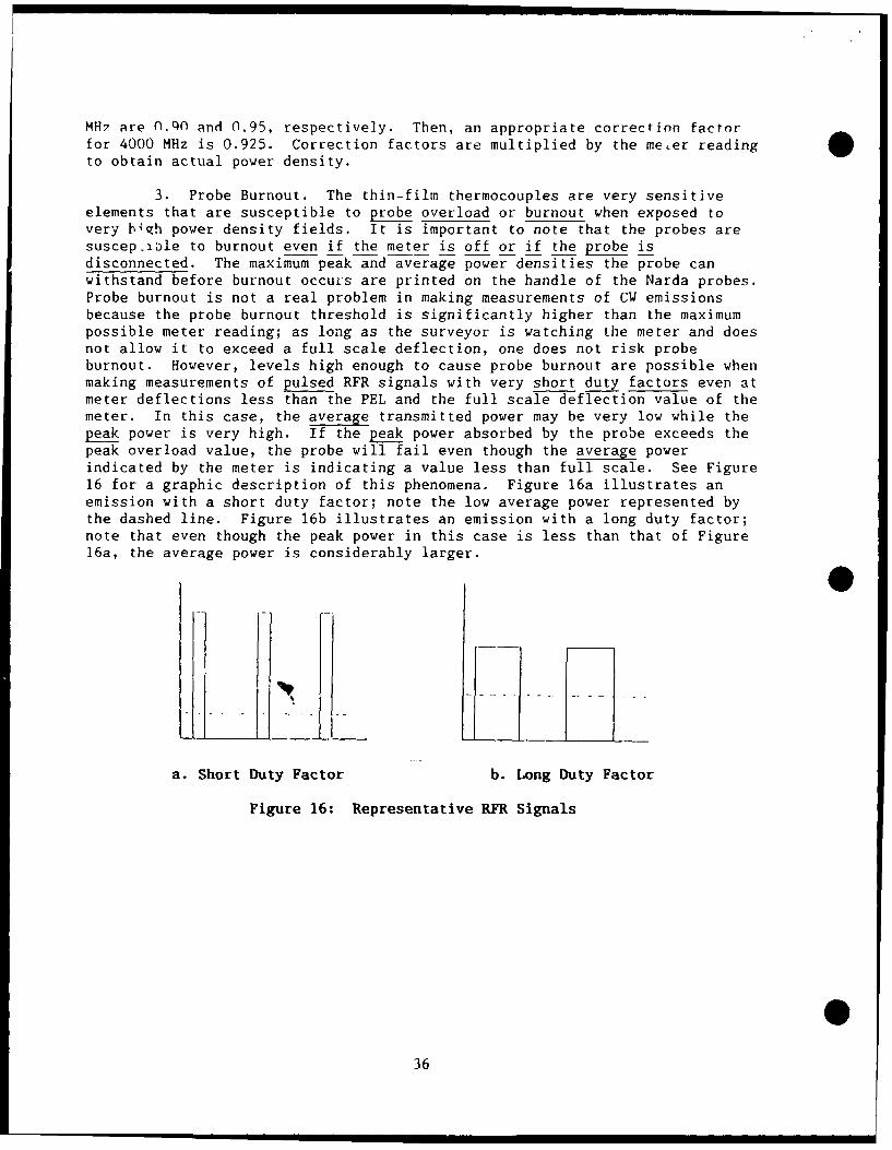
MH7 are 0.QO and 0.95, respectively. Then, an appropriate correction factorfor 4000 MHz is 0.925. Correction factors are multiplied by the me,er readingto obtain actual power density.
3. Probe Burnout. The thin-film thermocouples are very sensitiveelements that are susceptible to probe overload or burnout when exposed tovery bhh power density fields. It is important to note that the probes aresuscep.lble to burnout even if the meter is off or if the probe isdisconnected. The maximum peak and average power densities the probe canwithstand before burnout occurs are printed on the handle of the Narda probes.Probe burnout is not a real problem in making measurements of CW emissionsbecause the probe burnout threshold is significantly higher than the maximumpossible meter reading; as long as the surveyor is watching the meter and doesnot allow it to exceed a full scale deflection, one does not risk probeburnout. However, levels high enough to cause probe burnout are possible whenmaking measurements of pulsed RFR signals with very short duty factors even atmeter deflections less than the PEL and the full scale deflection value of themeter. In this case, the average transmitted power may be very low while thepeak power is very high. If the peak power absorbed by the probe exceeds thepeak overload value, the probe will fail even though the average powerindicated by the meter is indicating a value less than full scale. See Figure16 for a graphic description of this phenomena. Figure 16a illustrates anemission with a short duty factor; note the low average power represented bythe dashed line. Figure 16b illustrates an emission with a long duty factor;note that even though the peak power in this case is less than that of Figure16a, the average power is considerably larger.
a. Short Duty Factor b. Long Duty Factor
Figure 16: Representative RFR Signals
36
Equation 17, if used, can prevent a costly accident and a red face!
PD = DF x BR / CF (17)max
Where: PD = Maximum meter reading before burnoutmax
DF = Duty Factor (Equation 3)
BR = Burnout Rating (Peak Power Density Rating)
CF = Correction Factor (Printed or probe handle forfrequency of operation)
If PD is greater than full scale there is no cause for concern provided themaxsurveyor does not exceed full scale. On the other hand, if PD is less thanfull scale reading, the surveyor must monitor the meter at allmefmes. If themeter reading exceeds PD , even briefly, probe burnout is risked. Notethese examples: max
Example 1: PW = 2 ps, PRF = 360, DF = 0.00072, CF = 1
PD = [0.00072 x 300000 (8623 probe)1/1 = 216 mW/cm2
max
Conclusion: Low risk of 2probe burnout since 216 mW/cm2 is
W greater than full scale of 100 mW/cm (8623 probe).
Example 2: PW = 0.25 ps, PRF = 800, DF = 0.0002, CF = 1
PD = [0.0002 x 300000 (8623 probe)] = 60 mW/cm2
max
Conclusion: High ris of probe burnout since 60 mW/cm2 isless than full scale of 100 mW/cm (8623 probe).
The inability to zero an instrument is a telltale sign of a possible probeburnout. Test the probe cable for a possible wire break, since this conditioncan exhibit a like effect.
4. Zero Drift. Zero drift is inherent with instrumentation thatutilizes thermocouples and other temperature sensitive components. Prematurecommencement of a survey without allowing the electronics to reach equilibriumand a change in ambient temperature during a survey are common causes of zerodrift. To reduce errors from zero drift, we recommend:
a. Connect and turn instrumentation "on" at least 10 minutesbefore survey measurements are made. Locate instruments in the sameenvironment you intend to survey--it doesn't make much sense to equilibrateinstrumentation indoors if one intends to survey outdoors at a different
*temperature.
37
b. Periodically check the zero of an instrument during surveymeasurements, especially if one is moving between areas of significantlydifferent ambient temperatures (sunny vs shaded). To re-zero instrumentationduring a survey one can:
(1) Completely leave the RFR field.
(2) Completely shield the probe in a metal can or Nardainstrument case if it provides shielding (most do!).
(3) Shield the probe with your body. Your body willeffectively absorb signals with frequencies higher than 1000 MHz.
5. Out of Band Response. Potential measurement errors can occur whenusing a probe outside of its frequency range. Although this problem can occurwith all probes, it is more marked in magnetic field probes due to periodicresonances above their rated band specification. If a signal coincides withan out of band resonance frequency of the probe, a high false meter indicationmay result. Electric field probes typically give a low false meter indicationsince resistive dipoles result in very damped resonances. Only use probesthat have been calibrated and fully cover the emitter frequency range.
C. AFOEHL Equipment Loan
1. General. Most BES have a Narda 8611 meter and 8623 probe toperform RFR measurements. For the most part, this should be adequate for 90%of the required survey work. AFOEHL has a sizable inventory of Nardaequipment for internal survey work and loan to other bases. Table 7 lists ourcurrent inventory of Narda equipment and features.
2. All requests for loan of Narda equipment should be made in writingunless it is an emergency request. Requests should be sent to:
AFOEHL/RZC AV 240-3486Brooks AFB TX 78235 Comm. (512) 536-3486,
along with emitter operating frequencies (unclassified only). Equipmentshould be returned to:
AFOEHL/ECH AV 240-2142Equipment Loan Comm. (512) 534-2142.
Contact AFOEHL/RZC for all questions regarding equipment malfunction ortechnical capabilities.
3. For bases in PACAF or USAFE, be sure to coordinate first with yourtheater servicing laboratory.
38
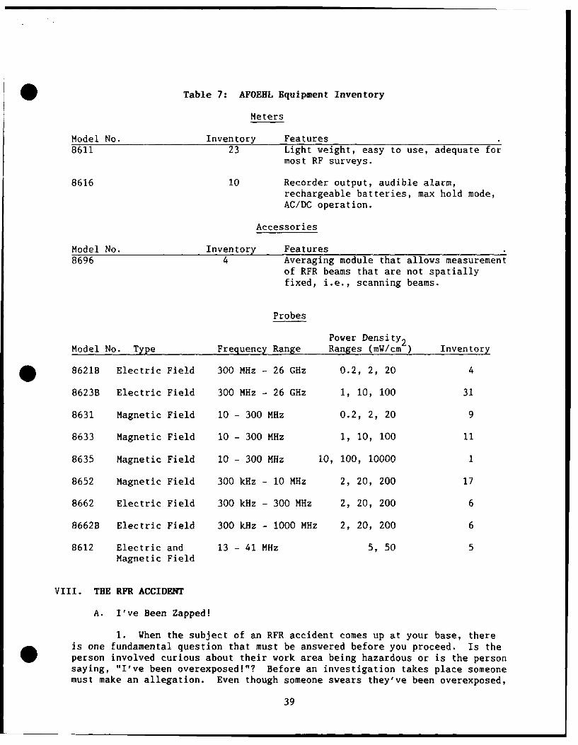
Table 7: AFOEHL Equipment Inventory
Meters
Model No. Inventory Features8611 23 Light weight, easy to use, adequate for
most RF surveys.
8616 10 Recorder output, audible alarm,rechargeable batteries, max hold mode,AC/DC operation.
Accessories
Model No. Inventory Features8696 4 Averaging module that allows measurement
of RFR beams that are not spatiallyfixed, i.e., scanning beams.
Probes
Power Density2Model No. Type Frequency Range Ranges (mW/cm-) Inventory
* 8621B Electric Field 300 MHz - 26 GHz 0.2, 2, 20 4
8623B Electric Field 300 MHz - 26 GHz 1, 10, 100 31
8631 Magnetic Field 10 - 300 MHz 0.2, 2, 20 9
8633 Magnetic Field 10 - 300 MHz 1, 10, 100 11
8635 Magnetic Field 10 - 300 MHz 10, 100, 10000 1
8652 Magnetic Field 300 kHz - 10 MHz 2, 20, 200 17
8662 Electric Field 300 kHz - 300 MHz 2, 20, 200 6
8662B Electric Field 300 kHz - 1000 MHz 2, 20, 200 6
8612 Electric and 13 - 41 MHz 5, 50 5Magnetic Field
VIII. THE RFR ACCIDENT
A. I've Been Zapped!
1. When the subject of an RFR accident comes up at your base, thereis one fundamental question that must be answered before you proceed. Is the
person involved curious about their work area being hazardous or is the personsaying, "I've been overexposed!"? Before an investigation takes place someonemust make an allegation. Even though someone swears they've been overexposed,
39
it isn't necessarily true. On the other hand, if someone says it happened,there's no recourse but to investigate the incident.
2. The reasons you have to proceed with the investigation should befairly obvious. If the person waj, in fact overexposed, we want to know aboutthe details in order to provide proper medical attention. On the other hand,if the person was not overexposed, the findings of the investigation shouldhelp alleviate any anxiety held by any individual; the investigation shouldallow the BES to prevent future incidents by providing education.Additionally, an investigation is necessary for potential future legalprbblems.
3. The benefits of a good RFR emitter inventory and baseline surveyshow through during a suspected overexposure incident. If the BES hasperformed a thorough inventory and baseline on all potentially hazardousemitters, BES should be able to make an initial determination of exposurereceived to individuals once the workplace supervisor or unit RPO calls withinitial data. In fact, from our experience, a majority of the incidentsreported to us had absolutely no potential for overexposure and could havebeen resolved by a telephone conversation between the BES and the reportingworkplace if the BES had good documentation in their case file. Even in thesecases, it is good practice to make a site visit at the minimum. In themajority of these cases, the individuals reported no symptoms, rather theirclaims where based on confusion and fear, ultimately the lack of RFReducation.
B. Who Does What?
1. Now let's suppose that you have determined that someone definitelyclaimed that he has been overexposed. There is a precise set of steps tofollow. There are three things that should be taken care of... right now.
a. Make sure the individual reports to the flight surgeon orother available physician for a physical exam (see AFOSH Std 161-9). EHScompletes an AF Form 190 in detail, correctly describing the subjectivesymptoms and any findings of the examination. Be careful with the wording.If one were to say, "individual was treated for a pounding headache andtwitching eye because he received a massive dose of microwave radiation," youhave opened the door to all kinds of trouble. Instead, "individual complainsof a headache and irritated eyes and claims they are the result of hismicrowave exposure" would be better. The main thing is to be sure thedescription is correct and factual. Most of the time it is the physician'sresponsibility to write the narrative on the AF Form 190, this is where a goodworking relationship between EHS, BES, and the flight surgeon helps.
b. Next, as soon as possible get a signed narrative statementfrom the individual exposed and any others involved like operators ormaintenance personnel who were present when the incident occurred. By the waygo over these statements and make sure they are legible and make sense.
c. If desired call AFOEHL/RZC, AUTOVON 240-3486, and discuss theincident with us. We can help insure that there are no steps overlooked andadvise you on how to proceed. For PACAF and USAFE bases, please contact yourtheater servicing lab first.
40
2. Some BES prefer to do their own investigations. That is fine; weare more than willing to give you telephone consultation if needed. If youdetermine that you do not have the ability to perform the investigation,AFOEHL is willing to investigate the incident; all requests for our assistancemust be forwarded through your major command BEE. We will respond, whenrequested, as soon as physically possible, usually within two or three days,sooner, if necessary.
C. Investigate and Reconstruct.
1. If you choose to handle the entire matter yourself, here is the
rest of your obligation.
a. Taking care to protect yourself and your instrument,reconstruct the incident. Make measurements with the system set up, as nearlyas possible, as it was when the incident occurred. It may be that the powerdensity at the point of exposure is greater than thI measuring capability ofyour instrument (Narda 8623B, Max Scale = 100 mW/cm ). If this s the caseyou should make multiple measurements starting at, say, 10 mW/cm and move upin increments until you reach the limit. These data can be plotted onsemi-log paper and the actual exposure value can be estimated byextrapolation2 Also, AFOEHL has Narda 8644S probes that allow measurements tpto 2000 mW/cm . These probes are biing phased out, but a new probe that willallow measurements up to 1000 mW/cm will replace them. In either case, thisequipment can be borrowed from AFOEHL.
b. When determining the total exposure, you must know theduration of the exposure. This can be very tricky, because the time estimatesof the exposee and witnesses are usually very exaggerated. Ask the exposee torepeat his actions and use a stop watch to get a better idea of the actualexposure time. The shorter the time, the more important this becomes.
c. Photographs are a very important part of your investigation.With the transmitter shut down, ask everyone to position themselves exactly asthey were during the incident. Then take photographs from a few differentangles. You can have the base photo lab do the photography, but you must tellthem exactly what you want.
D. Crucial Documentation. Like all gratifying and rewarding jobs,this one is not finished until the paperwork is done. That's right--you mustwrite a report. In your report, BES should detail the case as far as whathappened, to whom, when, and where. You should tell what you did, how you didit, what you concluded, and what follow-up action you recommend. All thismust be completed in 30 days! BES provides the report to the EHS, who thenhas 45 days to summarize the entire investigation (see AFOSH Std 161-9 forreport requirements) and distribute it.
E. A Calming Influence. Last, but by far not least, this advice:keep your cool. You should have a calming influence on those around you.Don't show surprise at a high level reading or give your suppositions aboutthe medical implications of the exposure. Avoid actions that only result in
* fanning the flames of a fire. People tend to think and expect the worst.Some suspect that the "system" will try to cover the truth. Your bearing and
41
attitude will go a long way to relieve anxieties and calm fears. Be frank,open, confident, and reassuring.
IX. THE VOICE OF EXPERIENCE
A. Most of Your Work.
1. By now you have probably realized that the most difficult part ofsetting up an RFR program is getting started--putting together that emitterinventory and making the initial surveys. Once you have this behind you, therest falls easily in place. Most of the work is getting out and finding justwhere things are and how to control them.
2. When you have a feel for your emitters and their hazard-producingpotential, you will also have a feel for which emitters will require surveywork. If an emitter, regardless of size and output power, is located so thatit is normally inaccessible, there is no need to break your neck trying tomake measurements.
B. Your Knowledge Should Go A Long Way.
1. We encourage you to proceed with confidence. Take timeperiodically to review the guidelines we've given you. You have all you needto develop a very successful RFR protection program. If you run into a snag,we're as close as your telephone.
2. With every increasing public and command-level interest in RFRprotection, the pressure is on the base level aerospace medical team toestablish and conduct a viable program. In this guidebook you have theinformation you need to get well underway. With a little concentrated effort,your knowledge should go a long way.
442
APPENDIX A
Conversion Between Absolute Units and Decibel Units
0
043
(This page left blank)
44
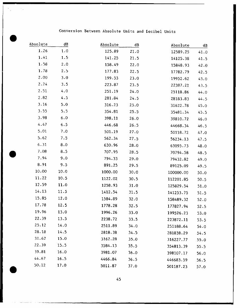
Conversion Between Absolute Units and Decibel Units0Absolute dB Absolute dB Absolute dB
1.26 1.0 125.89 21.0 12589.25 41.01.41 1.5 141.25 21.5 14125.38 41.51.58 2.0 158.49 22.0 15848.93 42.0
1.78 2.5 177.83 22.5 17782.79 42.5
2.00 3.0 199.53 23.0 19952.62 43.0
2.24 3.5 223.87 23.5 22387.21 43.5
2.51 4.0 251.19 24.0 25118.86 44.0
2.82 4.5 281.84 24.5 28183.83 44.53.16 5.0 316.23 25.0 31622.78 45.0
3.55 5.5 354.81 25.5 35481.34 45.5
3.98 6.0 398.11 26.0 39810.72 46.0
4.47 6.5 446.68 26.5 44668.34 46.5
5.01 7.0 501.19 27.0 50118.72 47.0
5.62 7.5 562.34 27.5 56234.13 47.5
6.31 8.0 630.96 28.0 63095.73 48.07.08 8.5 707.95 28.5 70794.58 48.5
7.94 9.0 794.33 29.0 79432.82 49.0
8.91 9.5 891.25 29.5 89125.09 49.5
10.00 10.0 1000.00 30.0 100000.00 50.0
11.22 10.5 1122.02 30.5 112201.85 50.5
12.59 11.0 1258.93 31.0 125829.54 51.0
14.13 11.5 1412.54 31.5 141253.75 51.515.85 12.0 1584.89 32.0 158489.32 52.0
17.78 12.5 1778.28 32.5 177827.94 52.519.96 13.0 1996.26 33.0 199526.23 53.0
22.39 13.5 2238.72 33.5 223872.11 53.525.12 14.0 2511.89 34.0 251188.64 54.0
28.18 14.5 2818.38 34.5 281838.29 54.531.62 15.0 3162.28 35.0 316227.77 55.0
22.39 15.5 3584.13 35.5 354813.39 55.539.81 16.0 3981.07 36.0 398107.17 56.0
44.67 16.5 4466.84 36.5 446683.59 56.5
50.12 17.0 5011.87 37.0 501187.23 57.0
45
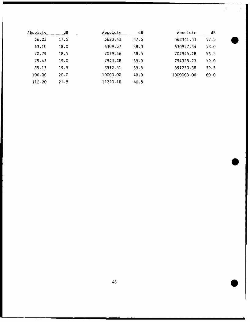
Absolute dB Absolute dB Absolute dB
56.23 17.5 5623.41 37.5 562341.33 57.5
63.10 18.0 6309.57 38.0 630957.34 58.0
70.79 18.5 7079.46 38.5 707945.78 58.5
79.43 19.0 7943.28 39.0 794328.23 59.0
89.13 19.5 8912.51 39.5 891250.38 59.5
100.00 20.0 10000.00 40.0 1000000.00 60.0
112.20 21.5 11220.18 40.5
46
APPENDIX B
Instructions for Completing AF Form 2759, Radiofrequency Emitter Survey
47
0
0
(This page left blank)
048
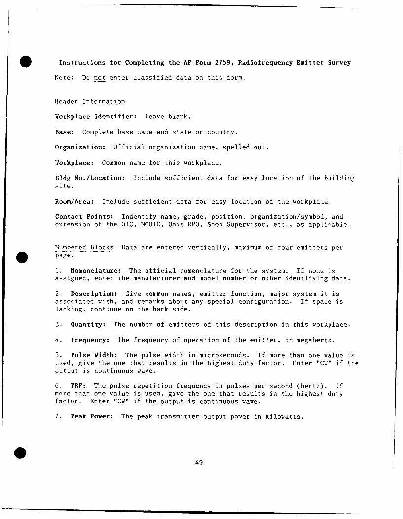
Instructions for Completing the AF Form 2759, Radiofrequency Emitter Survey
Note: Do not enter classified data on this form.
Header Information
Workplace Identifier: Leave blank.
Base: Complete base name and state or country.
Organization: Official organization name, spelled out.
lorkplace: Common name for this workplace.
Bldg No./Location: Include sufficient data for easy location of the buildingsite.
Room/Area: Include sufficient data for easy location of the workplace.
Contact Points: Indentify name, grade, position, organization/symbol, andextension of the OIC, NCOIC, Unit RPO, Shop Supervisor, etc., as applicable.
Numbered Blocks--Data are entered vertically, maximum of four emitters per* page.
I. Nomenclature: The official nomenclature for the system. If none isassigned, enter the manufacturer and model number or other identifying data.
2. Description: Give common names, emitter function, major system it isassociated with, and remarks about any special configuration. If space islacking, continue on the back side.
3. Quantity: The number of emitters of this description in this workplace.
4. Frequency: The frequency of operation of the emitter, in megahertz.
5. Pulse Width: The pulse width in microseconds. If more than one value isused, give the one that results in the highest duty factor. Enter "CW" if theoutput is continuous wave.
6. PRF: The pulse repetition frequency in pulses per second (hertz). Ifmore than one value is used, give the one that results in the highest dutyfactor. Enter "CW" if the output is continuous wave.
7. Peak Power: The peak transmitter output power in kilowatts.
449
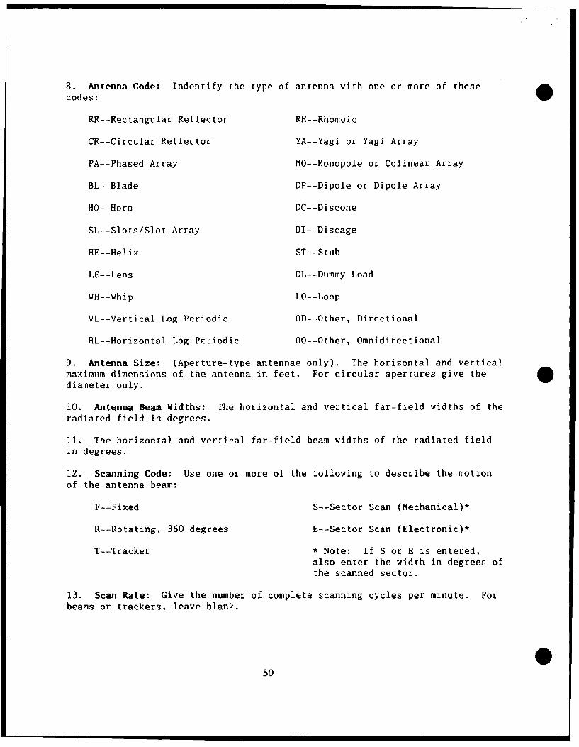
8. Antenna Code: Indentify the type of antenna with one or more of these
codes:
RR--Rectangular Reflector RH--Rhombic
CR--Circular Reflector YA--Yagi or Yagi Array
PA--Phased Array MO--Monopole or Colinear Array
BL--Blade DP--Dipole or Dipole Array
HO--Horn DC--Discone
SL--Slots/Slot Array DI--Discage
HE--Helix ST--Stub
LE--Lens DL--Dummy Load
WH--Whip LO--Loop
VL--Vertical Log Periodic OD- Other, Directional
HL--Horizontal Log Petiodic 00--Other, Omnidirectional
9. Antenna Size: (Aperture-type antennae only). The horizontal and verticalmaximum dimensions of the antenna in feet. For circular apertures give thediameter only.
10. Antenna Beam Widths: The horizontal and vertical far-field widths of theradiated field in degrees.
11. The horizontal and vertical far-field beam widths of the radiated fieldin degrees.
12. Scanning Code: Use one or more of the following to describe the motionof the antenna beam:
F--Fixed S--Sector Scan (Mechanical)*
R--Rotating, 360 degrees E--Sector Scan (Electronic)*
T--Tracker * Note: If S or E is entered,also enter the width in degrees ofthe scanned sector.
13. Scan Rate: Give the number of complete scanning cycles per minute. Forbeams or trackers, leave blank.
50
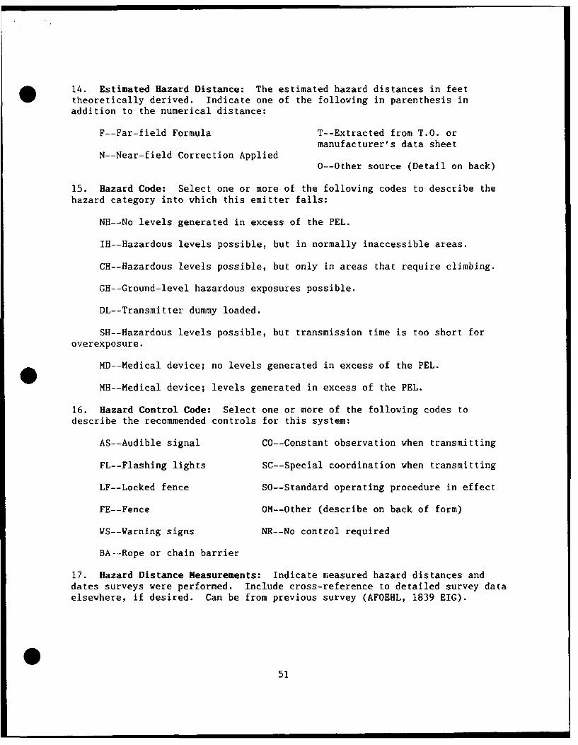
14. Estimated Hazard Distance: The estimated hazard distances in feettheoretically derived. Indicate one of the following in parenthesis inaddition to the numerical distance:
F--Far-field Formula T--Extracted from T.O. ormanufacturer's data sheet
N--Near-field Correction Applied0--Other source (Detail on back)
15. Hazard Code: Select one or more of the following codes to describe thehazard category into which this emitter falls:
NH--No levels generated in excess of the PEL.
IH--Hazardous levels possible, but in normally inaccessible areas.
CH--Hazardous levels possible, but only in areas that require climbing.
GH--Ground-level hazardous exposures possible.
DL--Transmitter dummy loaded.
SH--Hazardous levels possible, but transmission time is too short foroverexposure.
MD--Medical device; no levels generated in excess of the PEL.
MH--Medical device; levels generated in excess of the PEL.
16. Hazard Control Code: Select one or more of the following codes todescribe the recommended controls for this system:
AS--Audible signal CO--Constant observation when transmitting
FL--Flashing lights SC--Special coordination when transmitting
LF--Locked fence SO--Standard operating procedure in effect
FE--Fence OM--Other (describe on back of form)
WS--Varning signs NR--No control required
BA--Rope or chain barrier
17. Hazard Distance Measurements: Indicate measured hazard distances anddates surveys were performed. Include cross-reference to detailed survey dataelsewhere, if desired. Can be from previous survey (AFOEHL, 1839 EIG).
551
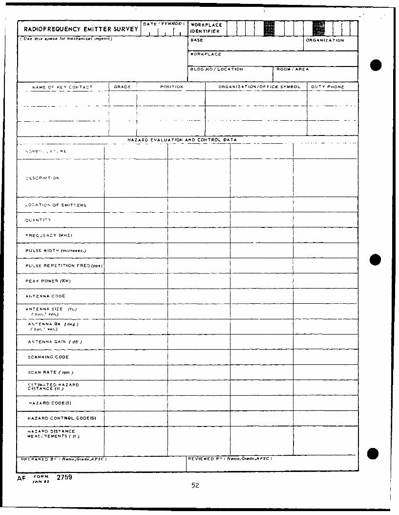
DATE 'YYMMDD) WORKPLACE
RADIOFREQUENCY EMITTER SURVEY tIDENTIFI WRKLAE
[ame th'E space lot mechanical imprinr) BASETIFIE
BASE ORGANIZATION
WORKPLACE
BLDG NO/ LOCATION ROOM/AREA 0NE KEY CONTACT GRADE POSITION ORGANIZATION/OFFICE SYMBOL DUTY PHONE
HAZARD EVALUATION AND CONTROL DATA
ZESCRIPTION
LOCATIL-,
OF EMITTERS
QUANTITY
FREQUENCY (MHZ)
PULSE WIDTH (microaec.)
PULSE REPETITION FREQ(pps) __.0
PEAK POWER (KW)
ANTENNA CODE
ANTENNA SIZE fit.)
( ho,. I ve,.)
ANTENNA Blh fde )( hot. I ler.)
ANTENNA GAIN (dA)
-.CANNING CODE
SCAN RATE (rpm)
EETIMITED HAZARDEE ISTA NCE (fU)
HAZARD CODEfS)
HAZARD CONTROL CODE(S)
HAZADD DISTANCEMEAS2 EMENTS ( f )
PPE-OAPED BY ' Nome,GrdeAFSC)' REVIEWED IB I 'Nam.,OedeAFSC .
AF FORM 2759JAN 82
52
APPENDIX C
RFR Emitter Survey Data Base
53
(This page left blank)
54
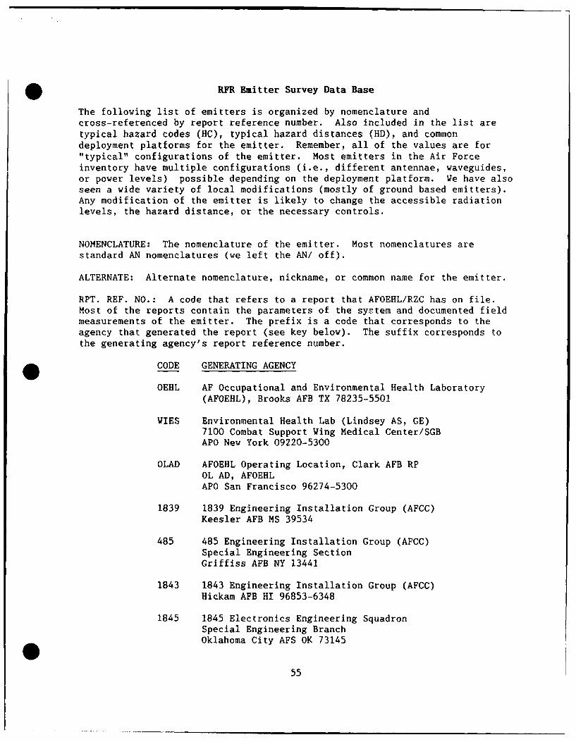
*RFR Emitter Survey Data Base
The following list of emitters is organized by nomenclature andcross-referenced by report reference number. Also included in the list aretypical hazard codes (HC), typical hazard distances (HD), and commondeployment platforms for the emitter. Remember, all of the values are for"typical" configurations of the emitter. Most emitters in the Air Forceinventory have multiple configurations (i.e., different antennae, waveguides,or power levels) possible depending on the deployment platform. We have alsoseen a wide variety of local modifications (mostly of ground based emitters).Any modification of the emitter is likely to change the accessible radiationlevels, the hazard distance, or the necessary controls.
NOMENCLATURE: The nomenclature of the emitter. Most nomenclatures are
standard AN nomenclatures (we left the AN/ off).
ALTERNATE: Alternate nomenclature, nickname, or common name for the emitter.
RPT. REF. NO.: A code that refers to a report that AFOEHL/RZC has on file.Most of the reports contain the parameters of the system and documented fieldmeasurements of the emitter. The prefix is a code that corresponds to theagency that generated the report (see key below). The suffix corresponds tothe generating agency's report reference number.
CODE GENERATING AGENCY
OEHL AF Occupational and Environmental Health Laboratory(AFOEHL), Brooks AFB TX 78235-5501
WIES Environmental Health Lab (Lindsey AS, GE)7100 Combat Support Wing Medical Center/SGBAPO New York 09220-5300
OLAD AFOEHL Operating Location, Clark AFB RPOL AD, AFOEHLAPO San Francisco 96274-5300
1839 1839 Engineering Installation Group (AFCC)Keesler AFB MS 39534
485 485 Engineering Installation Group (AFCC)Special Engineering SectionGriffiss AFB NY 13441
1843 1843 Engineering Installation Group (AFCC)Hickam AFB HI 96853-6348
1845 1845 Electronics Engineering SquadronSpecial Engineering BranchOklahoma City AFS OK 73145
55
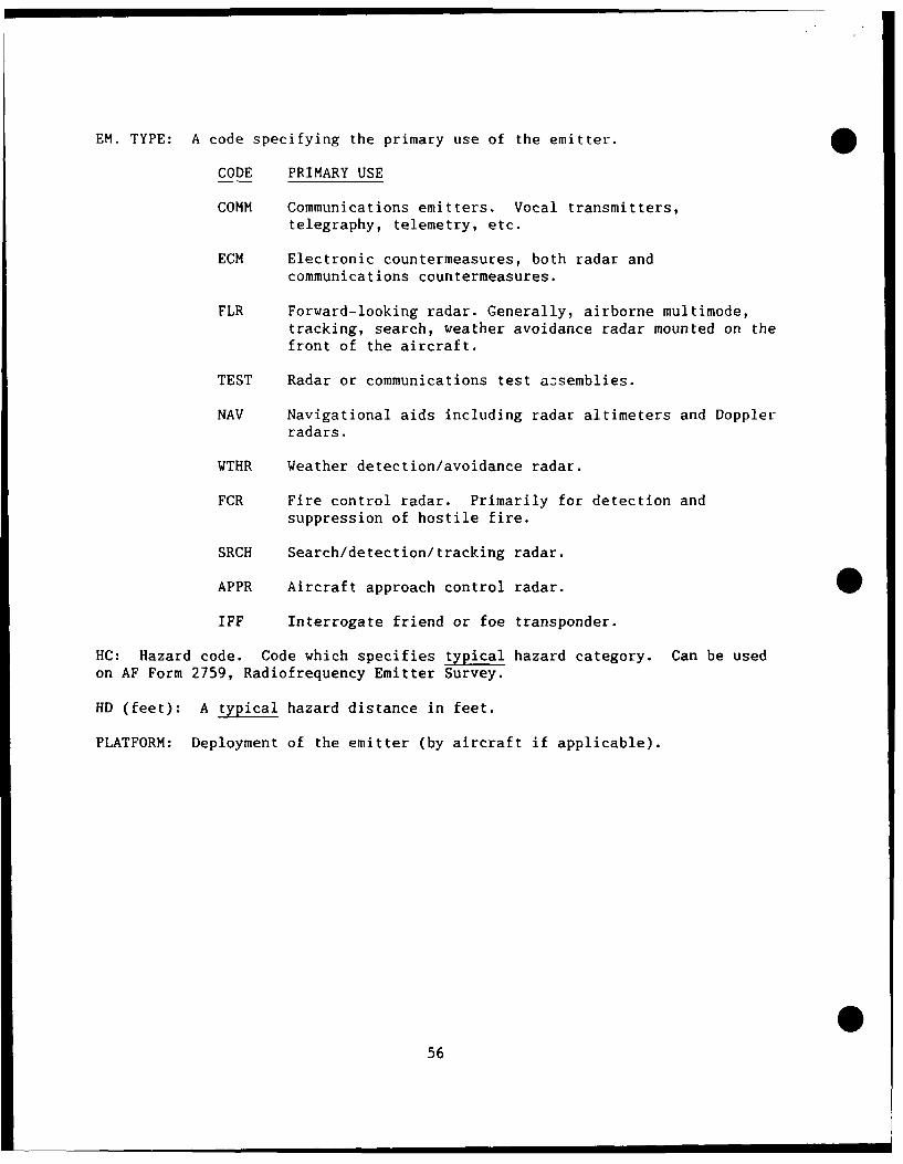
EM. TYPE: A code specifying the primary use of the emitter.
CODE PRIMARY USE
COMM Communications emitters. Vocal transmitters,telegraphy, telemetry, etc.
ECM Electronic countermeasures, both radar andcommunications countermeasures.
FLR Forward-looking radar. Generally, airborne multimode,tracking, search, weather avoidance radar mounted on thefront of the aircraft.
TEST Radar or communications test assemblies.
NAV Navigational aids including radar altimeters and Dopplerradars.
WTHR Weather detection/avoidance radar.
FCR Fire control radar. Primarily for detection andsuppression of hostile fire.
SRCH Search/detection/tracking radar.
APPR Aircraft approach control radar.
IFF Interrogate friend or foe transponder.
HC: Hazard code. Code which specifies typical hazard category. Can be used
on AF Form 2759, Radiofrequency Emitter Survey.
HD (feet): A typical hazard distance in feet.
PLATFORM: Deployment of the emitter (by aircraft if applicable).
056
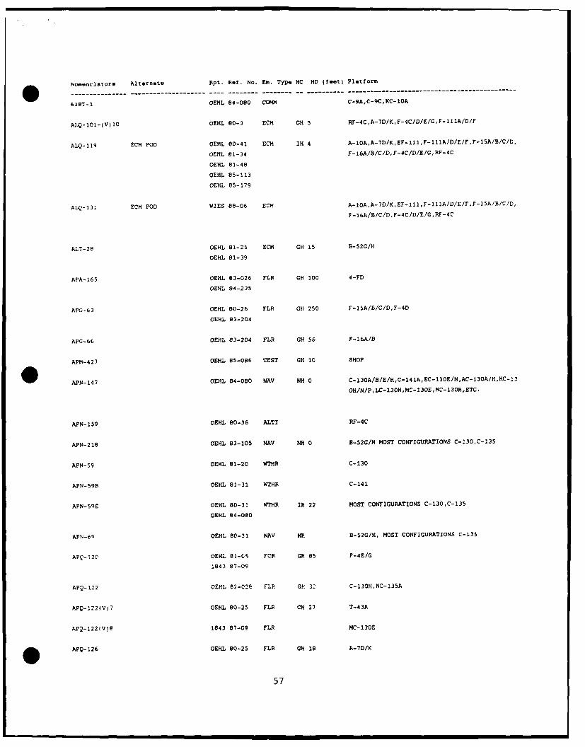
N1o~nclotore Alternate Rpt. Rel, No., Sa. Type HC HO (feet) PlotfoIe
61ST-1 OENL 84-080 C0OM C-9A,C-9C,KC-IOA
ALQ-101-(V)1O OEHL 80-3 ECN CH 5 Rr-4C,A-7DfK,F-4C/D/E/G,F-111A/D/r
ALQ-119 EON POD OEHL 80-41 EON IN 4 A-IOA,A-7D/K,EF-111,F-111A/D/E/F,F-15A/B/C/D,
OEHL 81-34 F-16A/B/C/D,F-4C/D/E/GRF-4C
OEHL 81-48
OEHL 85-113
OEHL 85-179
ALQ-131 EON POD 'W1ES 86-06 ECM A-O,-DKE-1,-II/)EFF1ABCD
F-16A/B/C/D F-4C/D/E/G .RF-4C
ALT-28 OEHL 81-25 ECM GH 15 B-52G/H
OEHL 81-39
APA-165 OEHL 83-026 FLR GH 100 4-FD
OEHL 84-235
APG-.63 OEHL 80-26 FLR CH 250 F-15A/B/C/D,F-4D
OEHL 83-204
APG-66 OEHL 83-204 FLR GH 56 F-16A/B
APM-427 OEHL 85-086 TEST OH 10 SHOP
APN-147 OEHL 84-080 NAV NH 0 C-130A/B/E/H,C-141A,EC-130E/H,AC-13OA/H,HC-13
OH/N/P. LO-130H,NC-130E,NC-130H,ETC.
APN-159 OEHL 80-36 ALTI RF-4C
AYN-218 OEHL 83-105 HAV NH 0 B-520/N MOST CONFIGURATIONS 0-130,0-135
APN-59 OEHL 81-20 WTHR C-130
AP14-59B OEHL 81-31 1QTHR C-141
APN-59E OEHL 80-31 WTHR IH 22 MOST CONFIGURATIONS C-130,C-135
OEHL 84-080
APN-69 OEHL 80-31 NAy NHi B-52G/H, MOST CONFIGURATIONS C-135
APQ-120 OEHL 01-C5~ FOR OH 85 F-4E/G
1843 87-09
APQ-122 OEHL 82-026 FLP. OH 3- C-130H,NC-135A
APQ-122(V)7 OEHL 80-25 FLR CH 27 T-43A
kPQ-1221V)e 1843 87-09 FLR MC-230E
APQ-126 OEHL 80-25 FLR OH 18 A-7D/K
57
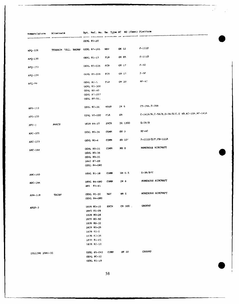
Nomnclature Alternate Rpt. Ref. No. Em. Type HC HD (feet) Platform
OEHL 81-20
APQ-128
TERRAIN nOLL. RADAR OEHL 87-105 NAV GH 12 F-11D
APQ-130 OEML 81-13 FLR GH 85 F-111D
APQ-153 OEHL 85-026 FCR GH 17 F-5E
APQ-159 OEHL 85-026 FCR GH 17 F-5F
APQ-99 OtEL 80-5 FLF GH 20 RF-4C
0EHL 83-300
OEHL 80-40
OEHL 87-057
OEHL 80-56,
APS-113 OEHL 80-36 WTHR IH 6 CT-39A,T-39A
APS-13 3 OEHL 85-020 FLu GH C-141A/B,C-5A/B,E-3A/B/CE 48,KC-10A,NC-141A
APY-1 AWACS 1839 84-37 SRCH IH 1300 E-3A/B
ARC-1O5 OEHL 80-36 COmm SH 3 RF-4C
ARC-123 OEHL 80-4 COt SH 10' F-111D/E/F,FB-111A
ARC-164 OVHL 80-31 COMM NH 0 NUMEROUS AIRCRAFT
OEHL 80-36
OEHL 80-31
1843 87-09
OEHL 84-080
ARC-265 OEHL 82-18 COmm Gm 0.5 E-3A/B/C
ARC-1b6 OEHL 84-080 COMM IN 6 NUMEROUS AIRCRAFT
485 85-41
ARN-118 TACAN OEHL 81-20 NAV NMH 0 NUMEROUS AIRCRAFT
OEHL 84-080
ARSR-3 1839 80-10 SRCH CH 300 GROUND
1845 81-05
1839 80-26
1839 80-50
1839 80-32
1839 80-29
2839 81-5
139 E2-36
1839 81-01
1839 82-13
COLLINS 208U-10 OEHL 85-042 COMm GH 20 GROUND
OEHL 80-32OEHL 81-18
58
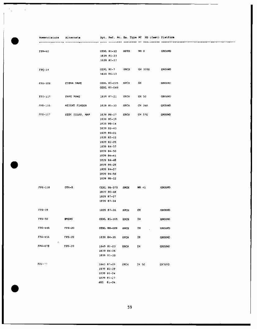
Nomenclature Alternate Rpt. Ret. No. Em. Type NC HO (feet) Platform
FPN-62 OEHL 81-12 APPR NH) 0 GROUND
1839 81-23
1839 83-27
FPQ-14 QEHL 02-7 SRCH GH 3200 GROUND
1839 86-13
FP'S-1O8 COBRA DANE OEHL 85-025 SRCH GA GROUND
OEAL 85-049
FPS-115 PAVE PAWS 1839 87-21 SRCH GA 50 GROUND
FPS-116 HEIGHT FINDER 1839 85-33 SRCA CH 360 GROUND
FPS-117 SEEK IGLOO, MAP 2839 86-17 SRCH CH 570 GROUND
1839 85-19
1839 88-14
1839 82-43
1839 88-01
1839 85-02
1839 82-05
1839 84-57
1839 84-50
1839 84-41
1839 84-48
1839 84-28
1839 84-27
1839 84-56
1839 86-12
FPS-Ile 0TH-B OEHL 86-075 SRCH NH <1 GROUND
1839 80-18
1839 87-37
1839 87-34
FPS-19 1839 87-36 SRCH CA GROUND
FP'S-50 BMEWS OEHL 85-105 SRCH IA GROUND
FP'S-64A FP'S-20 OEHL 88-009 SRCH IN GROUND
FPS-65A FPS-20 1839 84-30 SRCN IN GROUND
FPS-67B FPS-20 1845 81-03 SRCNq IN GROUND
1839 84-26
1839 81-10
FS7 1843 87-09 SRCH IA SO GROUND
1839 83-2e
1839 83-24
1839 e'-27
485 81-09
59
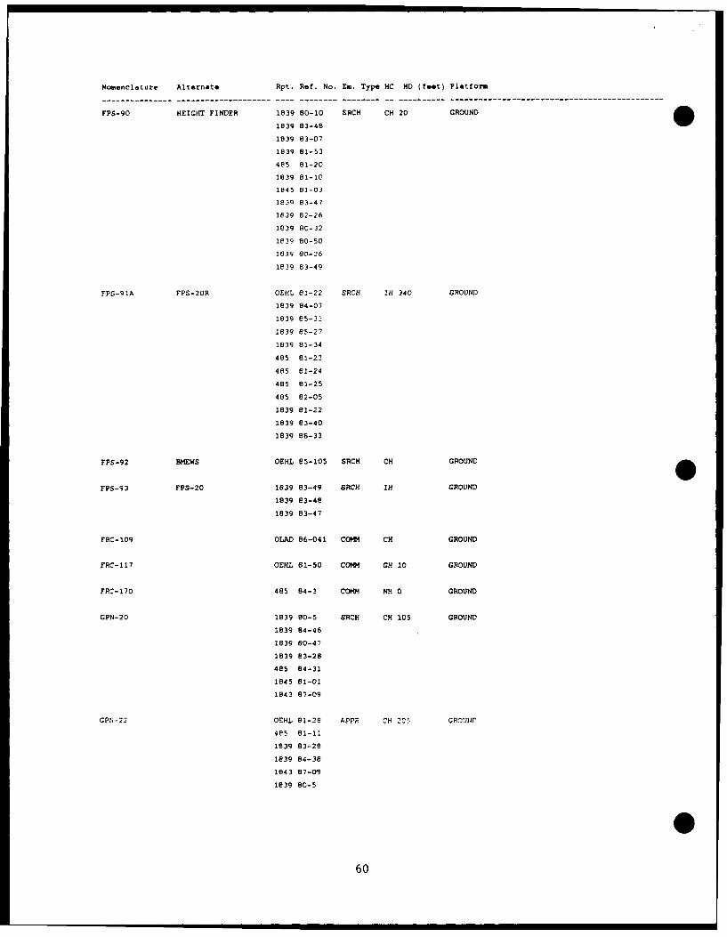
Nomenclature Alternate Rpt. Ref. No. Em. Type HC NO (teet) Platform
FPS-90 HEIGHT FINDER 1839 80-10 SRCH CH 20 GROUND
1839 83-48
1839 83-07
1839 81-53
485 81-20
1839 81-10
1845 81-03
1839 83-47
1839 82-26
1839 80-32
1839 80-50
1839 60-26
1839 83-49
FPS-91A FPS-20R OEHL 81-22 SRCH IH 340 GROUND
1839 84-07
1839 85-33
1839 85-27
1839 81-34
485 81-23
485 81-24
485 81-25
485 82-05
1839 81-22
1839 83-40
1839 86-33
FPS-92 BMEWS OEHL 85-105 SRCH CH GROUND
FPS-93 FPS-20 1839 83-49 SRCH IN GROUND
1839 83-48
1839 83-47
FRC-109 OLAD 86-041 COmm CH GROUND
FRC-117 OEHL 81-50 COmm GH 10 GROUND
FRC-170 485 84-3 COm NH 0 GROUND
GPN-20 1839 80-5 SRCH CH 105 GROUND
1839 84-46
1839 80-47
1839 83-28
485 84-31
1845 81-01
1843 87-09
GPr4-22 OEHL 81-28 APPF CH 205 GPDUt;L
485 81-11
1839 83--28
1839 84-38
1843 87-09
1839 80-5
60
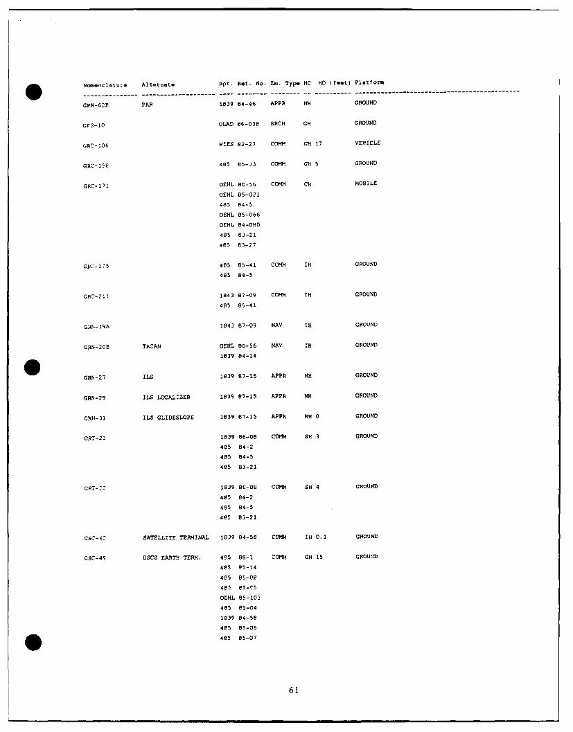
Nomenclature Alternate Rpt. Ref. No. Ex. Type HC HD (feet) Platform
GPN-62B PAR 1839 84-46 APPR NH GROUND
GPS-10 OLAD 86-038 SRCH GH GROUND
GRC-106 WIES 82-27 Comm GH 17 VEHICLE
GRC-158 485 85-33 COmm GH 5 GROUND
GRC-171 OEHL 80-56 COMm CH MOBILE
OEHL 85-021
485 84-5
OEHL 85-066
OEHL 84-080
485 83-21
485 83-27
GRC-175 485 85-41 COmm IH GROUND
485 84-5
GRC-211 1843 87-09 COMM IH GROUND
485 85-41
GRN-19A 1843 87-09 NAN IH GROUND
GRN-20B TACAN OEHL 80-56 NAV IH GROUND
1839 84-14
0 GRN-27 11.5 1839 87-15 APPR NH GROUND
GRN-29 ILS LOCALIZER 1839 87-15 APPR NH GROUND
G.V-31 ILS GLIDESLOPE 1839 87-15 APPR NH 0 GROUND
GRT-21 1839 86-08 COMM SH 3 GROUND
485 84-2
485 84-5
485 83-21
CRT-=2 1839 86-08 COMm SH 4 GROUND
485 84-2
485 84-5
485 83-21
GSC-42 SATELLITE TERMINAL 1839 84-58 COmm IH 0.1 GROUND
GSC-49 DSCS EARTH TERM. 4e5 88-1 COMM GH 15 GROUND
485 L5-14
485 85-08
485 e5-C5
OEHL 85-103
485 85-04
I839 84-5e
4e5 85-06
485 85-07
61
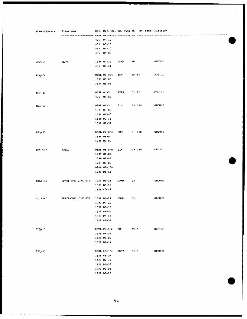
Nomenclature Alternate Rpt. Ref. No. Em. Type HC HD (faet Platform
--------------- -------------------- ---- --------- -------------------- ---------------------------------------------
485 87-13
4P5 85-13
485 85-10
485 85-09
GSC-52 SAMT 1839 87-22 CoMm NH GROUND
485 87-21
M I-74 OEHL 84-086 ECH GH 88 MOBILE
1839 88-08
1839 88-08
MPN-13 OEHL 80-5 APPR IH 60 MOBILE
485 81-09
MPS-TI OEHL 82-3 SIm CH 120 GROUND
1839 88-09
1839 88-05
1839 83-14
1839 82-31
OEHL 84-086 ECM IH 330 GROUND
1839 88-09
1839 88-09
MSr-TlA MUTES OEHL 86-070 sit GH 350 GROUND
1839 88-09
1839 88-08
1839 88-06
OEVL 87-156
1839 81-18
SGLS-46 SPACE-GND LINK SYS. 1839 86-21 COMM IH GROUND
1839 86-13
1839 85-17
SG'S-60 SPACE-GND LINK SYS. 1839 86-21 COmm IH GROUND
1839 87-22
1839 86-13
1839 86-01
1839 85-17
1839 86-03
TLQ-11 OEHL 87-156 ECM CH 5 MOBILE
1e39 88-06
1839 88-08
1839 82-31
TP -43 OEHL 87-156 SRZP. IN 1 GROUIJD
1E39 88-09
1839 82-31
1839 88-07
I139 88-06
1839 88-05
62
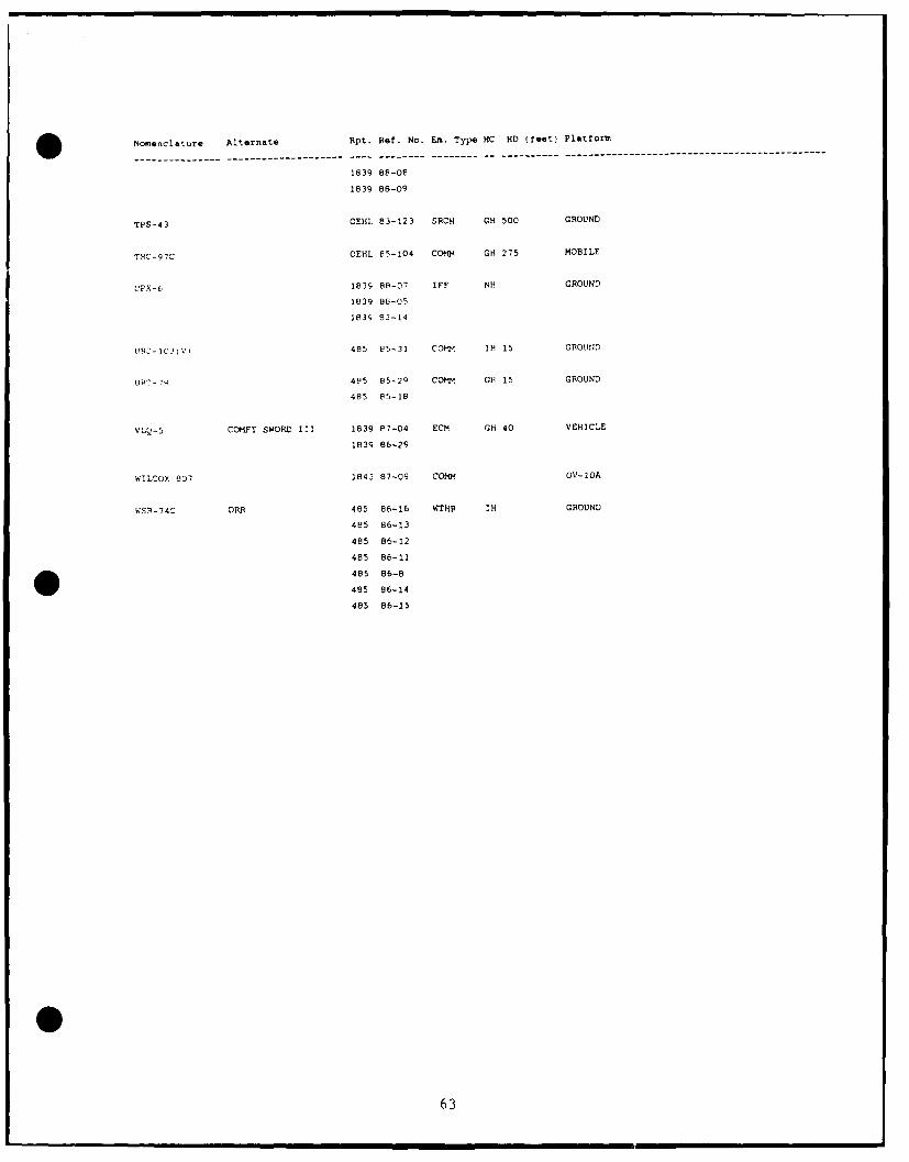
Nomenclature Alternate Rpt. Ref. No. Em. Type HC HD (feet) Platform
--------- -------- ---------------------- ------------------------------------------------------------
1839 88-08
1839 88-09
TPS-43 OEHL 83-123 SRCH GH 500 GROUND
THC-97C OEHL 85-104 COMM GH 275 MOBILE
VPX-6 1839 88-07 IFF NH GROUND
1839 86-05
1839 83-14
UR:-1C:V, 485 e5-31 COM. iH 15 GROUIND
LIP"- ?Q 4F5 85-29 COM. GH 15 GROUND
485 85-18
VLQ-5 COMFY SWORD II 1839 e7-04 ECM GH 40 VEHICLE
1839 86-29
WILCOX 807 1843 87-09 COMM OV-IOA
WSP-74C ORR 485 86-16 WTHR IH GROUND
485 86-13
485 86-12
485 86-11
485 86-8
485 86-14
485 86-15
63
0
0
(This page left blank) 664
APPENDIX D
Survey of Ground Based Emitters
0
65
(This page left blank)
66
Survey of Ground Based Emitters
1. These systems will generally bear "AN" nomenclatures beginning with theletter F, M, G, or T, denoting the following (with examples):
a. Fixed (AN/FPN-47, AN/FPS-116, AN/FRT-49)
b. Mobile (AN/MPN-14, AN/MPS-9, AN/MRC-113)
c. Ground (AN/GPN-12, AN/GRC-75, AN/GRN-9)
d. Transportable (AN/TPS-43, AN/TRC-97, AN/TPB-lB)
2. Ground mounted radar systems are sometimes capable of operating in morethan one mode. It is, therefore, vital that during the presurvey, carefulconsideration be given to all of the possible modes to insure thatmeasurements will be made with the system operating in the mode that willcreate the "worst case" (highest peak power, highest duty factor, andnarrowest beam configuration).
3. A visual inspection of the site should be made to determine if the mainradiated beam is normally accessible to personnel. If not, then there is nohazard, but it must be recognized that there may be future modifications ofeither the emitter itself or the environment that may make the beamaccessible.
4. If the main beam is normally accessible to personnel, antenna rotation (ifapplicable) must be stopped and access to the main beam gained at a distancefrom the antenna determined during presurvey. The beam size, shape, andcharacter should be determined, then the actual PEL level should be located.In order to assure that meter readings are accurate, care must be taken tokeep the probe handle parallel to the beam axis, or perpendicular to theemitter surface as appropriate. In addition, try to avoid beam reflectionfrom nearby objects.
5. Regardless of whether or not the main beam is normally accessible, thearea surrounding the antenna itself should be carefully probed for possiblehazardous levels of energy, as well as a determination made as to what mightbe required for personnel to access hazardous levels in the immediate vicinityof the antenna.
WARNING: When surveying aperture type systems, the area between thefeedhorn and the reflector is normally very dangerous, both to personneland to the RFR power density probes.
6. Operating personnel should be asked to accurately determine the actualpower input value at the time measurements were made. Many ground systemshave integral directional couplers and power meters available for thispurpose.
067
7. An inspection should be conducted to determine if the system underevaluation has adequate interlock mechanisms, and ascertain if they can be orare regularly bypassed for routine maintenance purposes.
8. A visual inspection should be made to determine if there are RFR warningsigns (AF Forms 737 or 747) in sufficient numbers, and at appropriatelocations.
9. Operations and maintenance personnel should be interviewed relative totheir acquaintance with the potential health hazards associated with radiofrequency radiation emissions. It is often possible to gain further insightinto this topic by observing the activities of these personnel as they goabout their normal activities. Technical Orders for each emitter beingevaluated should be reviewed for the presence and adequacy of warnings topersonnel regarding these hazards. It should also be determined if there areup-to-date written operating and accident reporting standard operatingprocedures (SOPs) that provide acceptable personnel protection. SOPs are moreimportant than the TO as far as review by BES is concerned.
6
68
APPENDIX E
Survey of Airborne Emitters
669
(This page left blank)
0
700
Survey of Airborne Emitters
1. These systems usually bear "AN" nomenclatures beginning with the letter A,like AN/APQ-120, AN/APN-59B, AN/APG-63, AN/ASG-21, etc. There are, however, anumber of atypical nomenclatures like MA-1, MD-9, R-14C, Multimode, etc.During the presurvey phase of an evaluation, an assessment must be made to becertain that no emitters of interest have been overlooked because of anatypical nomenclature.
2. When airborne systems are live-fired on the ground, the main beam isalmost always normally accessible to personnel, and the possible hazards mustbe recognized by both operating and survey personnel prior to measurements.
3. Airborne antennas, in general, and RADAR antennas especially are often ator very near eye-level, and it must be recognized that, in the normal courseof operations, the main beam is often directed downward.
4. Airborne RADAR systems are often capable of operating in many modes. Itis vital that an adequate presurvey analysis be accomplished to insure thatmeasurements will be made with the system operating in the mode that willcreate the "wor-t case" (highest average power output and narrowest beamwidths).
5. When surveying airborne systems, it is essential that the aircraft bepositioned with an ample clear area in front of the antenna to precludeunnecessary radiation of other aircraft, vehicles, buildings, etc. Thisdistance should be determined during the presurvey. The antenna should bestopped and positioned dead ahead in azimuth, and at zero degrees or slightlyabove in elevation. This last point is necessary to prevent reflections fromthe ground and thus create unwanted, unpredictable, and possibly dangerous"hot spots."
6. The antenna should be approached from a known safe distance (based oncalculations or other source) and the main beam located. Once found, itssize, shape, and other characteristics should be determined, then theboundaries for the PEL should be determined. Care must be taken to maintainthe probe along the main beam axis.
7. The area immediately surrounding the antenna (to the side and behind)should be probed for hazardous side lobes and back scatter. These are notcommonly seen. As with ground aperture systems, the area between the feedhornand the reflector is very dangerous and should be avoided by both the surveyinstrument and personnel.
8. It is highly desirable to evaluate a minimum of three transmitters (threedifferent aircraft) of a given emitter. In addition, actual power inputvalues should be obtained from operating personnel if possible. Many airbornesystems have integral direction couplers for this purpose.
9. The potential for personnel RFR hazards in the avionics maintenance shops
is great. Most systems are ordinarily fired into dummy loads in the shops,
71
bli some require actual radiation through an antenna. In the former case, thedummy loads should be evaluated for effectiveness, in the latter case, theevaluation should be similar to that of an aircraft mounted system and shouldinclude a careful evaluation for possible reflections and scattering withinthe shop area. An inspection should be conducted to make certain that thearea immediately in front of any radiating antenna is off limits to personnel,vehicles, etc., to a distance appropriate for the emitter.
10. The shop area should be inspected for the presence of AF Forms 737 or 747RFR warning signs (if warranted) in sufficient numbers and at appropriatelocations.
11. Both operation and maintenance personnel should be interviewed relativeto their acquaintance with the potential health hazards associated with radiofrequency emissions. In addition, it will be useful to observe theiractivities in the shop and on the flight line to gain some perception of theirattitudes regarding these hazards.
12. Technical Orders for each emitter being evaluated should be reviewed forthe presence and adequacy of warning to personnel regarding RFR hazards. Itshould also be determined if there are up-to-date written operating andaccident reporting SOPs that provide acceptable personnel protection.
13. During flight line measurements, observations should be made to determineif there are adequate and effective procedures to protect personnel duringroutine ground firing of these systems.
72
APPENDIX F
Survey of Medical RFR Emitters
73
(This page left blank)
074
Survey of Medical RFR Emitters
i. The most common medical RFR emitter is the diathermy machine. These unitscan usually be found in the physical therapy section of USAF Hospitals andclinics. Medical diathermy machines in the U.S. are authorized to operate ona number of frequencies, but by far the most common are 13.56 and 27.12 MHz(short wave diathermy) and 2450 MHz (microwave diathermy). Most units within
the Air Force Medical Service are short wave diathermy.
2. The prime concern in evaluating diathermy units is NOT with the patientundergoing treatment, since it is assumed the therapy is being administered by
or under the supervision of competent medical personnel. There are somepotential hazards to operators of this equipment, particularly the S-bandunits (2450 MHz). Evaluation may be necessary to be assured that thetherapists operate the equipment in a manner that will not cause them to beunnecessarily exposed, particularly to the head and shoulders.
3. It is important to note that the proper equipment for measuring short wavediathermy units is not available at most bases. Necessary equipment can be
loaned from AFOEHL.
0
0
0
(This page left blank)
06
76I
S
APPENDIX G
Radio Frequency Radiation Survey Checklist
7
77

S
0
(ThiE; page let t blani'
0/8
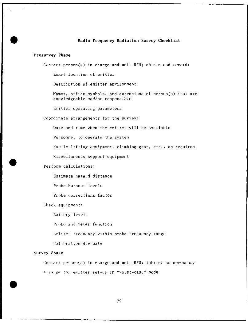
Radio Frequency Radiation Survey Checklist
Presurvey Phase
Contact person(s) in charge and unit RPO; obtain and record:
Exact location of emitter
Description of emitter environment
Names, office symbols, and extensions of person(s) that areknowledgeable and/or responsible
Emitter operating parameters
Coordinate arrangements for the survey:
Date and time when the emitter will be available
Personnel to operate the system
Mobile lifting equipment, climbing gear, etc., as required
Miscellaneous support equipment
0Perform calculations:Estimate hazard distance
Probe burnout levels
Probe corrections factor
Check equipment:
Battery levels
Ptobe and metPr function
Eli tI trlequency within probe frequency range
'iI I hbtat ion due date
Survey Phase
C:ontact person(s) in charge and unit RPO; inbrief as necessary
,,1 inge troi emitter set-up in "worst-cas-" mode
079
Using correct technique, locate and record (if practical):
PEL hazard radius and height above ground
All areas that the PEL could be exceeded
Levels at work stations and "normally-accessible" areas
Any "hot spots"
Observe and note:
Adequacy of warning signs and access-limiting devices
Adequacy of any standard procedures used to reduce or avoid exposureto RFR
Degree of caution exercised by workers about handling a suspectedoverexposure
Outbrief as necessary
Post-survey Phase
Analyze results; formulate conclusions and recommendations
Prepare letter/report for concerned offices and unit RPO
File data, photographs, drawings, correspondence, etc., in shop folder
' •
800
APPENDIX H
Typical Beam Pattern Shape, Gain, and Beam Widths for Common Antennas
0
811

(This page left blank)
82
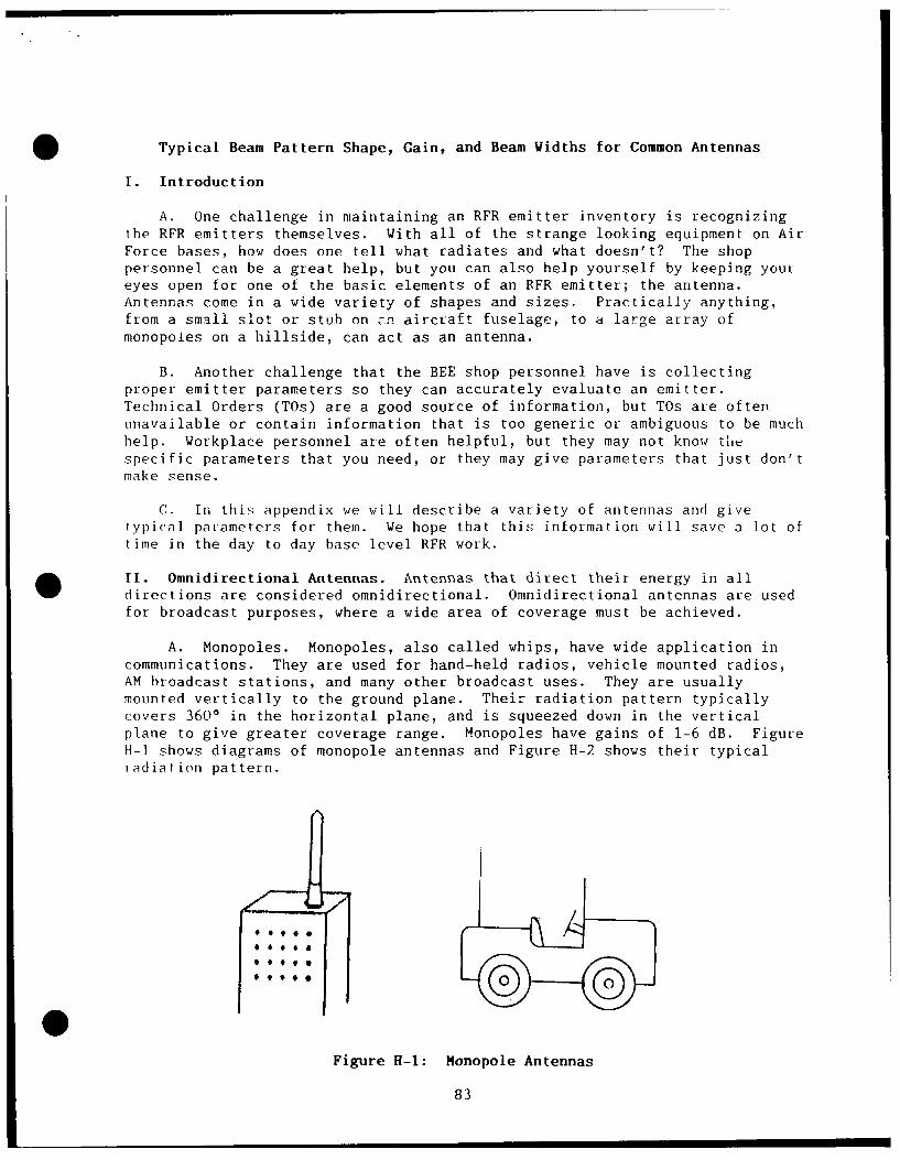
Typical Beam Pattern Shape, Gain, and Beam Widths for Common Antennas
I. Introduction
A. One challenge in maintaining an RFR emitter inventory is recognizingthe RFR emitters themselves. With all of the strange looking equipment on AirForce bases, how does one tell what radiates and what doesn't? The shoppersonnel can be a great help, but you can also help yourself by keeping youreyes open for one of the basic elements of an RFR emitter; the antenna.Antennas come in a wide variety of shapes and sizes. Practically anything,from a small slot or stub on a.n aircraft fuselage, to a large array ofmonopoles on a hillside, can act as an antenna.
B. Another challenge that the BEE shop personnel have is collectingproper emitter parameters so they can accurately evaluate an emitter.Technical Orders (TOs) are a good source of information, but TOs are oftenunavailable or contain information that is too generic or ambiguous to be muchhelp. Workplace personnel are often helpful, but they may not know thespecific parameters that you need, or they may give parameters that just don'tmake sense.
C. In this appendix we will describe a variety of antennas and givetypical parameters for them. We hope that this information will save a lot oftime in the day to day base level RFR work.
II. Omnidirectional Antennas. Antennas that direct their energy in alldirections are considered omnidirectional. Omnidirectional antennas are usedfor broadcast purposes, where a wide area of coverage must be achieved.
A. Monopoles. Monopoles, also called whips, have wide application incommunications. They are used for hand-held radios, vehicle mounted radios,AM broadcast stations, and many other broadcast uses. They are usuallymounted vertically to the ground plane. Their radiation pattern typicallycovers 3600 in the horizontal plane, and is squeezed down in the verticalplane to give greater coverage range. Monopoles have gains of 1-6 dB. FigureH-i shows diagrams of monopole antennas and Figure H-2 shows their typicaltadiation pattern.
0Figure H-l: Honopole Antennas
83
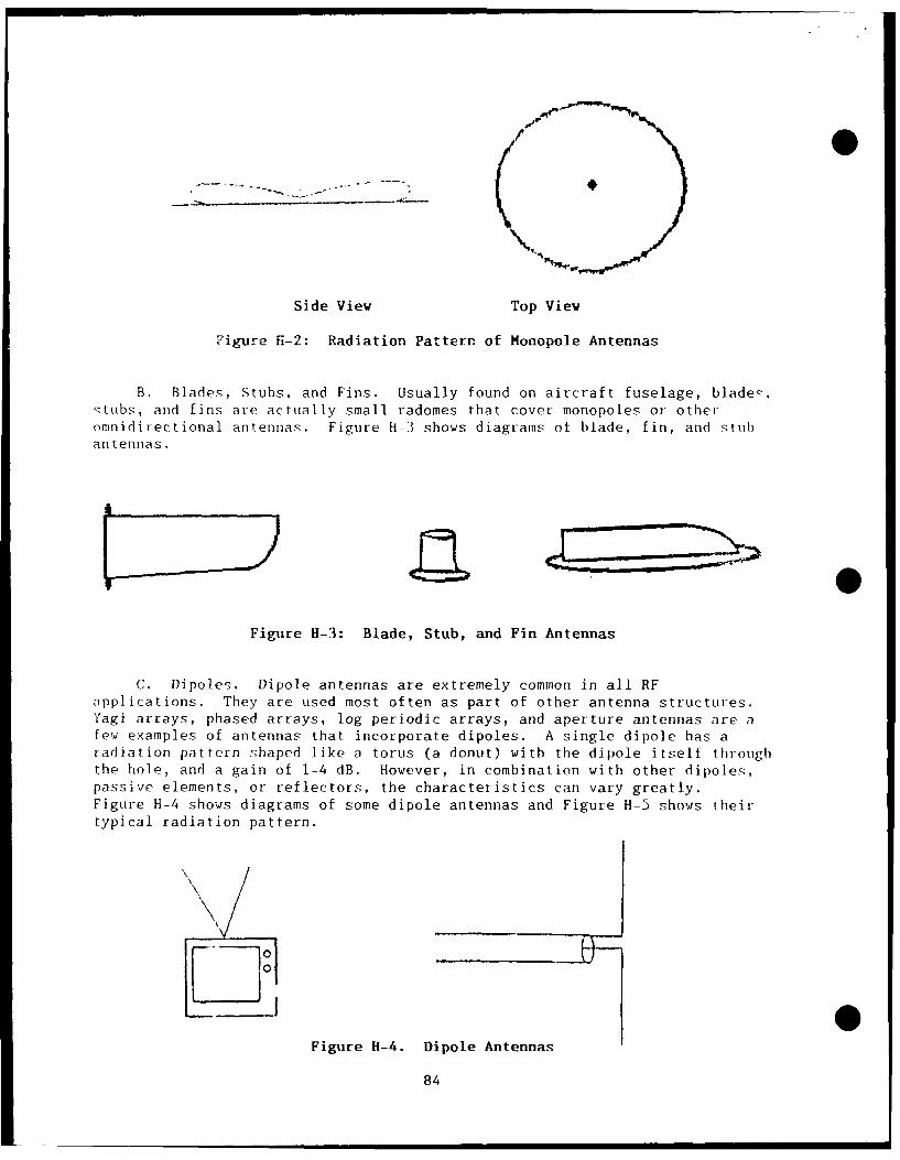
Side View Top View
Figure H-2: Radiation Pattern of Monopole Antennas
B. Blades, Stubs, and Fins. Usually found on aircraft fuselage, blade!:,stubs, and fins are actually small radomes that cover monopoles or otheromnidirectional antennas. Figure H-3 shows diagrams of blade, fin, and stubantennas.
Figure H-3: Blade, Stub, and Fin Antennas
C. Dipoles. Dipole antennas are extremely common in all RFapplications. They are used most often as part of other antenna structures.Yagi arrays, phased arrays, log periodic arrays, and aperture antennas are afew examples of antennas that incorporate dipoles. A single dipole has aradiation pattern shaped like a torus (a donut) with the dipole itself throughthe hole, and a gain of 1-4 dB. However, in combination with other dipoles,passive elements, or reflectors, the characteristics can vary greatly.Figure H-4 shows diagrams of some dipole antennas and Figure H-5 shows theirtypical radiation pattern.
VI
00Figure H-4. Dipole Antennas
84
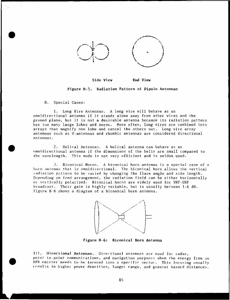
0
I 7
Side View End View
Figure B-5. Radiation Pattern of Dipole Antennas
D. Special Cases:
1. Long Wire Antennas. A long wire will behave as anomnidirectional antenna if it stands alone away from other wires and theground plane, but it is not a desirable antenna because its radiation patternhas too many large lobes and zeros. More often, long wires are combined intoarrays that magnify one lobe and cancel the others out. Long wire arrayantennas such as V-antennas and rhombic antennas are considered directionalantennas.
2. Helical Antennas. A helical antenna can behave as anomnidirectional antenna if the dimensions of the helix are small compared tothe wavelength. This mode is not very efficient and is seldom used.
3. Biconical Horns. A biconical horn antenna is a special case of ahorn antenna that is omnidirectional. The biconical horn allows the verticalradiation pattern to be varied by changing the flare angle and side length.Depending on feed arrangement, the radiation field can be either horizontallyor vertically polarized. Biconical horns are widely used for VHF-UHFbroadcast. Their gain is highly variable, but is usually between 1-6 dB.Figure H-6 shows a diagram of a biconical horn antenna.
Figure H-6: Biconical Horn Antenna
Ill. Directional Antennas. Directional antennas are used for radar,point to-point communications, and navigation purposes when the energy from anRFR emitter needs to be focused into a specific sector. This focusing usuallyIsults in higher power densities, longer range, and greater hazard distances.
85
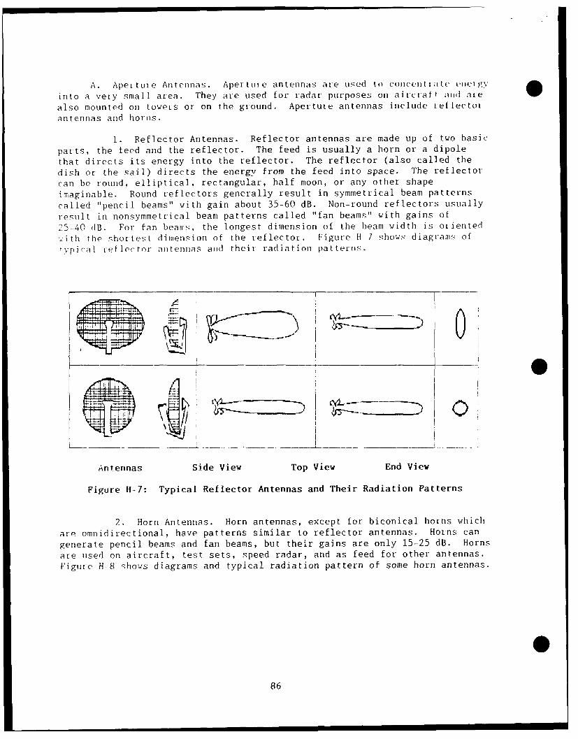
A. Aperture Antennas. Aperture antennas are used to concnt l.lie (e1 trgy
into a very small area. They are used for radar purposes on aircraft aiid are
also mounted on towers or on the ground. Aperture antennas include reflectot
antennas and horns.
1. Reflector Antennas. Reflector antennas are made up of two basic
parts, the feed and the reflector. The feed is usually a horn or a dipole
that directs its energy into the reflector. The reflector (also called the
dish or the sail) directs the energy from the feed into space. The reflector
can be round, elliptical, rectangular, half moon, or any other shape
imaginable. Round reflectors generally result in symmetrical beam patterns
called "pencil beams" with gain about 35-60 dB. Non-round reflectors usuallyresult in nonsymmetrical beam patterns called "fan beams" with gains of
25-40 dB. For fan beams, the longest dimension of the beam width is oriented
.ith the shortest dimension of the reflector. Figure H 7 shows diagrams of
typical reflector antennas and their radiation patterns.
Antennas Side View Top View End View
Figure H-7: Typical Reflector Antennas and Their Radiation Patterns
2. Horn Antennas. Horn antennas, except for biconical horns which
are omnidirectional, have patterns similar to reflector antennas. Horns can
generate pencil beams and fan beams, but their gains are only 15-25 dB. Horns
are used on aircraft, test sets, speed radar, and as feed for other antennas.
Figure H-8 qhows diagrams and typical radiation pattern of some horn antennas.
86
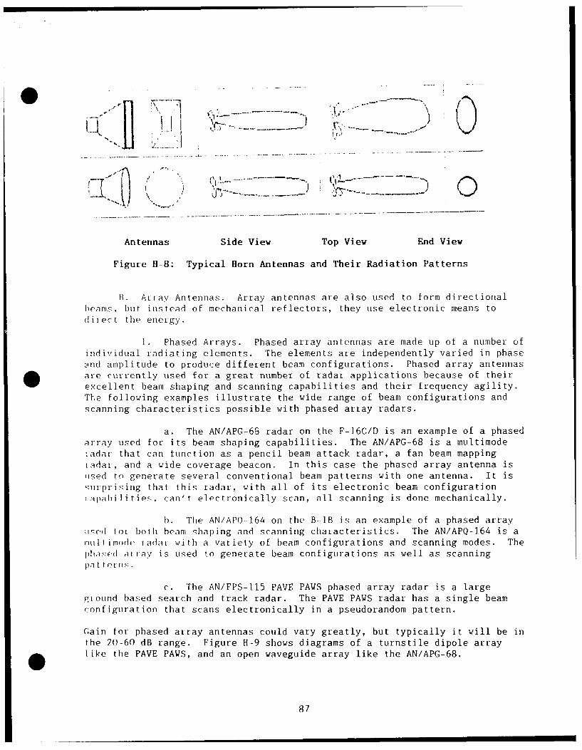
--.j .- .X ---,..,
Antennas Side View Top View End View
Figure H-8: Typical Horn Antennas and Their Radiation Patterns
B. Ariay Antennas. Array antennas are also used to form directionalheams, but instead of mechanical reflectors, they use electronic means todiiect the energy.
1. Phased Arrays. Phased array antennas are made up of a number ofindividual radiating elements. The elements are independently varied in phaseand amplitude to produce different beam configurations. Phased array antennasare currently used for a great number of radar applications because of theirexcellent beam shaping and scanning capabilities and their frequency agility.The following examples illustrate the wide range of beam configurations andscanning characteristics possible with phased array radars.
a. The AN/APG-65 radar on the F-16C/D is an example of a phasedarray used for its beam shaping capabilities. The AN/APG-68 is a multimodetadar that can function as a pencil beam attack radar, a fan beam mappingiadar, and a wide coverage beacon. In this case the phased array antenna isused to generate several conventional beam patterns with one antenna. It isurprising that this radar, with all of its electronic beam configuration
(apabilities. can't e]octronically scan, all scanning is done mechanically.
1. The AN/APQ-164 on the B lB is an example of a phased arrayii.d for both beam shaping and scanning characteristics. The AN/APO-164 is amultimode radar with a variety of beam configurations and scanning modes. Thepha .ed at ay is used to generate beam configurations as well as scanningpat terns.
c. The AN/FPS-115 PAVE PAWS phased array radar is a largegiound based search and track radar. The PAVE PAWS radar has a single beamconfiguration that scans electronically in a pseudorandom pattern.
Gain for phased array antennas could vary greatly, but typically it will be inthe 20-60 dB range. Figure H-9 shows diagrams of a turnstile dipole arraylike the PAVE PAWS, and an open waveguide array like the AN/APG-68.
87
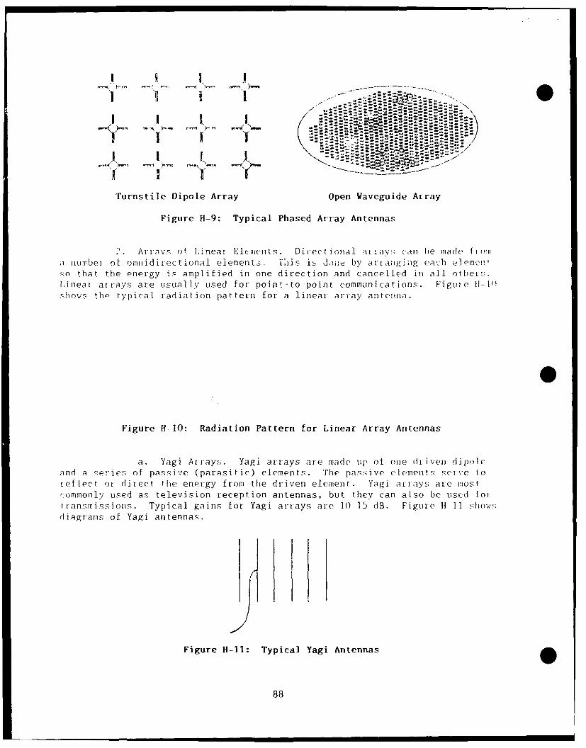
I I I I I I/
II 1 ".' "
Turnstile Dipole Array Open Waveguide Array
Figure H-9: Typical Phased Array Antennas
2. ArtaYs of ,i neal Elemen ts. Directional aii3y1 a Caln be made (1 1)1
a number of omnidirectional elements. This is don-e by artan-g ing each elemc!.so thar the energy is amplified in one direction and cancelled in all others'-.linear arrays are usually used for poin.-to -point communications. Figure 11-1)shows the typical radiation pattern for a linear array antenna.
Figure H-10: Radiation Pattern for Linear Array Antennas
a. Yagi Arrays,. Yagi arrays are made up of one driven dipoleand a series of passive (parasitic) elements. The pas.ive elements ,eve toreflect or direct the energy from the driven element. Yagi arrays are mostcommonly used as television reception antennas, but they can also be uscd [ortransmissions. Typical gains for Yagi arrays ate 10-15 dB. Figure H 11 sho,,,sdiagrams of Yagi antennas.
Figure H--l1: Typical Yagi Antennas
88
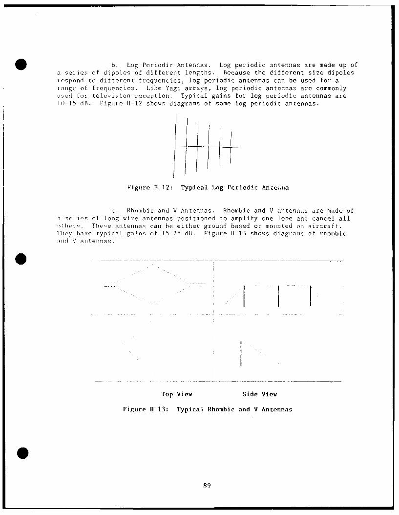
b. Log Periodic Antennas. Log periodic antennas are made up ofa seties of dipoles of different lengths. Because the different size dipolesiespond to different frequencies, log periodic antennas can be used for atange of frequencies. Like Yagi arrays, log periodic antennas are commonlyused for television reception. Typical gains for log periodic antennas arel0-15 dB. Figure H-12 shows diagrams of some log periodic antennas.
Figure H-12: Typical Log Periodic Ane.,nra
c. Rhombic and V Antennas. Rhombic and V antennas are made ofi eiies of long wire antennas positioned to amplify one lobe and cancel allothelv. These antennas can be either ground based or mounted on aircraft.Thc'r have typical gains of 15-25 dB. Figure H-13 shows diagrams of rhombic
and V antennas.
- -I -I
- I
Top View Side View
Figure H-13: Typical Rhombic and V Antennas
89
(This page left blank)
90
0
APPENDIX I
Basic Emitter Evaluations With Detailed Calculations
0
0 91
(This page left blank)
92
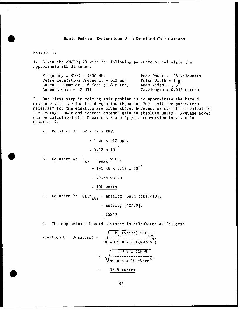
Basic Emitter Evaluations With Detailed Calculations
Example 1:
1. Given the AN/TPQ-43 with the following parameters, calculate theapproximate PEL distance.
Frequency = 8500 - 9600 MHz Peak Power = 195 kilowattsPulse Repetition Frequency = 512 pps Pulse Width = 1 8sAntenna Diameter = 6 feet (1.8 meter) Beam Width = 1.3Antenna Gain = 42 dBi Wavelength = 0.033 meters
2. Our first step in solving this problem is to approximate the hazarddistance with the far-field equation (Equation 10). All the parametersnecessary for the equation are given above; however, we must first calculatethe average power and convert antenna gain to absolute units. Average powercan be calculated with Equations 2 and 3; gain conversion is given inEquation 7.
a. Equation 3: DF = PW x PRF,
1 p us x 512 pps,
- 5.12 x 10⁻⁴
0 b. Equation 4: P av= Ppeak x DF,
- 195 kW x 5.12 x 10- 4
- 99.84 watts
100 watts
c. Equation 7: Gainabs = antilog [Gain (dBi)/l01,
= antilog 142/10],
= 15849
d. The approximate hazard distance is calculated as follows:
Pav (wat ts) x G absEquation 8: D(meters) ---Pav-w-tts)---Gabs
40 x n x PEL(mW/cm 2)
/ 100 W x 15849
0O x n x 10 mW/cm
= 35.5 meters
93
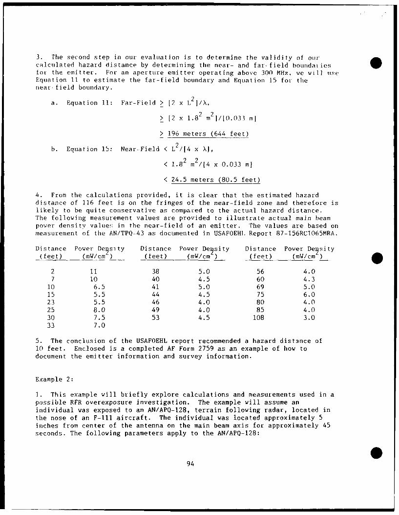
3. The second step in our evaluation is to determine the validity of ourcalculated hazard distance by determining the near- and far-field boundatiesfor the emitter. For an aperture emitter operating above 300 MHz, we will useEquation 11 to estimate the far-field boundary and Equation 15 fot thenear-field boundary.
a. Equation 11: Far-Field > 12 x L 2I/X,
> 12 x 1.82 m 21/10.033 ml
> 196 meters (644 feet)
b. Equation 15: Near-Field < L 2/14 x X1,
< 1.82 m2 /4 x 0.033 ml
< 24.5 meters (80.5 feet)
4. From the calculations provided, it is clear that the estimated hazarddistance of 116 feet is on the fringes of the near-field zone and therefore islikely to be quite conservative as compaued to the actual hazard distance.The following measurement values are provided to illustrate actual main beampower density value!; in the near-field of an emitter. The values are based onmeasurement of the AN/TPQ-43 as documented in USAFOEHL Report 87-156RCl065MRA.
Distance Power De9 sity Distance Power Degsity Distance Power Degsity(feet) (mW/cm ) (feet) (mW/cm) (feet) (mW/cm )
2 11 38 5.0 56 4.07 10 40 4.5 60 4.3
10 6.5 41 5.0 69 5.015 5.5 44 4.5 75 6.023 5.5 46 4.0 80 4.025 8.0 49 4.0 85 4.030 7.5 53 4.5 108 3.033 7.0
5. The conclusion of the USAFOEHL report recommended a hazard dist3nce of10 feet. Enclosed is a completed AF Form 2759 as an example of how todocument the emitter information and survey information.
Example 2:
1. This example will briefly explore calculations and measurements used in apossible RFR overexposure investigation. The example will assume anindividual was exposed to an AN/APQ-128, terrain following radar, located inthe nose of an F-Ill aircraft. The individual was located approximately 5inches from center of the antenna on the main beam axis for approximately 45seconds. The following parameters apply to the AN/APQ-128:
094
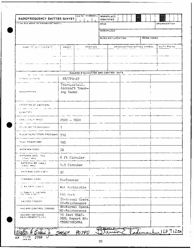
RAD10FREQUENCY ~ DMTE UVYjATE 'YYMMDD) WORKPLACERADIFREUENC EMTTERSUIVEYIDENTIFIER
Use thts space tor mechanical imprint) BASE ORGANIZATION
WORKPLACE
BLDG 4O / LOCATION ROOM/ AREA
NAME 0 @ S _0N7ACT GRADE POSITION ORGAHIZATION/OFFICE SYMBOL DUTY PHG'NE
HAZARD EVALUATION AND CONTROL DATA __ __ __
A~N/TPQ-43 _ _
LIESCR TfONAircraft Track-SC~rT!CNins Radar
LCATfON OF EMITTERSI
QUNIT Y
q : 11 N,7Y (M HZ) 8500 -9600 - _ _ _ _ _ _ _ _ _ _ _ _ _ _ _ _
PJLSE RLPEI1TION FREQ(pps) 512
PEAK< POWER (IV) 195
ANTENNA CODE ICR_____________ ______
ANTENNA SIZE: (ft.)6ftCrua
hot..' ver.)6ftCrua
ANTENNA 6%. (deg) 13Cruatic,. ver.) 13Crua
ANTrENNA GAIN (dV) 42
CANNING CODE T--Tracker
~,ANNAT (rtc INoi Applicable
-TMTL n4AZARD------
A~RD CO0DEIS Ifl-Ncrmal Op-era.__________________I G-Minteniance________
HAZARLD CONTROL CODE(S) 14R-Normal Opera,_____ ________WS -Maintenance ________
HAZARM DISTANCE 10 feet USAF-MEASLREMEN ( ft) OEHL Report 87-
W 4PPE S 1 56RC10O65MRA L 2S
AF VJN 2759 L/JAN S2
95
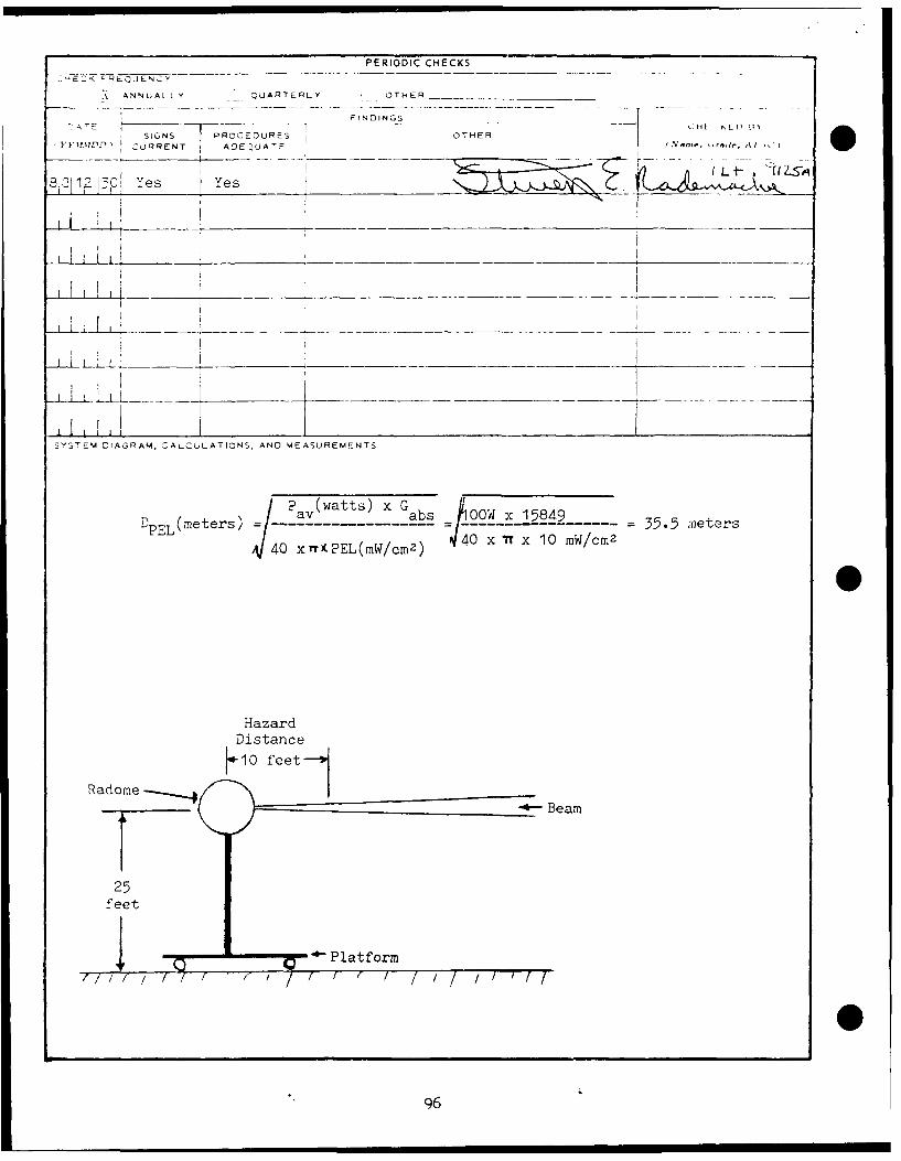
PERIODIC CHECKS
E-Z EQJENCY
A ANNLIALLY - QUARTERLY OTHER
-T F INDINGS O E
SIGNS PROCEDURESkL il
, T h.RRENT ADE UATE OTHR
-:1 _7 1-0 1 L -o ~ -3 Yes Yes
SYS' EM DIAGRAM, CALQuLATIONS. AND MEASUREMENTS
LPEL(rers 41 x (wts x mW7 2 ,O --- 35.5 meters
40 xrrxPEL(mW/cm2) 44 T 0rWcmn
HazardDistance
Radome 1 e tB a
25feet
.C 4 Platform
i0
96
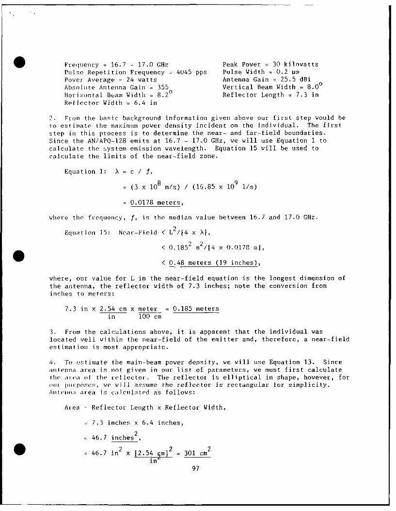
0 Frequency = 16.7 - 17.0 GHz Peak Power = 30 kilowattsPulse Repetition Frequency = 4045 pps Pulse Width = 0.2 PsPower Average = 24 watts Antenna Gain = 25.5 dBi
Absolute Antenna Gain = 355 Vertical Beam Width = 8.0°
Htorizontal Beam Width = 8.2° Reflector Length = 7.3 inReflector Width = 6.4 in
2. From the basic background information given above our first step would beto estimate the maximum power density incident on the individual. The firststep in this process is to determine the near- and far-field boundaries.Since the AN/APQ-128 emits at 16.7 - 17.0 GHz, we will use Equation 1 tocalculate the system emission wavelength. Equation 15 will be used tocalculate the limits of the near-field zone.
Equation 1: X = c / f,
= (3 x 10⁸ m/s) / (16.85 x 10⁹ l/s)
= 0.0178 meters,
where the frequency, f, is the median value between 16.7 and 17.0 GHz.
Equation 15: Near-Field < L2 /4 x X1,
< 0.1852 m2 /4 x 0.0178 mi,
< 0.48 meters (19 inches),
where, our value for L in the near-field equation is the longest dimension of
the antenna, the reflector width of 7.3 inches; note the conversion frominches to meters:
7.3 in x 2.54 cm x meter = 0.185 metersin 100 cm
3. From the calculations above, it is apparent that the individual waslocated well within the near-field of the emitter and, therefore, a near-fieldestimation is most appropriate.
4. To estimate the main-beam power density, we will use Equation 13. Sinceantenna area is not given in our list of parameters, we must first calculatethe aiva of the reflector. The reflector is elliptical in shape, however, for('ii ptiuPoscs, we will assume the reflector is rectangular for simplicity.AnlIfienn area is calculated as follows:
Area = Reflector Length x Reflector Width,
- 7.3 inches x 6.4 inches,
2- 46.7 inches
46.7 in2 x [2.54. m] = 301 cm
in
97
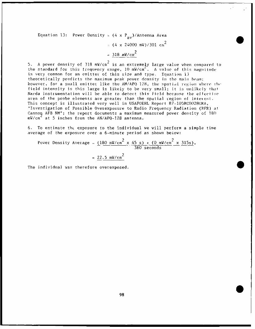
Equation 13: Power Density = (4 x P a)/Antenna Area
= (4 x 24000 mW)/301 cm2
= 318 mW/cm2
25. A power density of 318 mW/cm is an extremely large value when compared tothe standard for this frequency range, 10 mW/cm . A value of this magnitude,is very common for an emitter of this size and type. Equation 13theoretically predicts the maximum peak power density in the main beam:however, for a small emitter like the AN/APO-128, the spatial region where III(,field intensity is this large is likely to be very small; it is unlikely thatNarda instrumentation will be able to detect this field because the eflectivearea of the probe elements are greater than the spatial region of intetest.This concept is illustrated very well in USAFOEHL Report 87-105RCOO28GRA,"Investigation of Possible Overexposure to Radio Frequency Radiation (RFR) atCannog AFB NM"; the report documents a maximum measured power density of 180mW/cm at 5 inches from the AN/APQ-128 antenna.
6. To estimate thc exposure to the individual we will perform a simple timeaverage of the exposure over a 6-minute period as shown beiow:
Power Density Average = (180 mW/cm 2 x 45 s) + (0 mW/cm 2 x 315s),360 seconds
= 22.5 mW/cm2
The individual was therefore overexposed.
98
APPENDIX J
Terms List
99
(This page left blank)
100
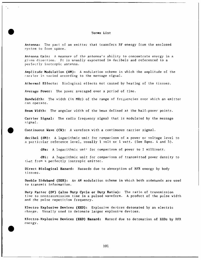
Terms List
Antenna: The part of an emitter that transfers RF energy from the enclosed
system to free space.
Antenna Gain: A measure of the antenna's ability to concentrate energy in agiven direction. It is usually expressed in decibels and referenced to a
perfectly isotropic antenna.
Amplitude Modulation (AM): A modulation scheme in which the amplitude of the
carrier is varied according to the message signal.
Athermal Effects: Biological effects not caused by heating of the tissues.
Average Power: The power averaged over a period of time.
Bandwidth: The width (in MHz) of the range of frcquencies over which an emittercan operate.
Beam Width: The angular width of the bean defined at the half-power points.
Carrier Signal: The radio frequency signal that is modulated by the messagesignal.
Continuous Wave (CW): A waveform with a continuous carrier signal.
decibel (dB): A logarithmic unit for comparison of a power or voltage level to
a particular reference level, usually 1 volt or 1 watt. (See Eqns. 4 and 5).
dBm: A logarithmic uni, for comparison of power to 1 milliwatt.
dBi: A logarithmic unit for comparison of transmitted power density totiat from i perfectly isotropic emitter.
Direct Biological Hazard: Hazards due to absorption of RFR energy by body
tissues.
Double Sideband (DSB): An AM modulation scheme in which both sidebands are used
to transmit information.
Duty Factor (DF) (also Duty Cycle or Duty Ratio): The ratio of transmissiontime to nontransmission time in a pulsed waveform. A product of the pulse widthand the pulse repetition frequency.
Electro-Explosive Devices (EED): Explosive devices detonated by an electric
chaige. Usually used to detonate larger explosie devices.
Electro-Explosive Devices (EED) Hazard: Hazard due to detonation of EEDs by RFRenergy.
0
101
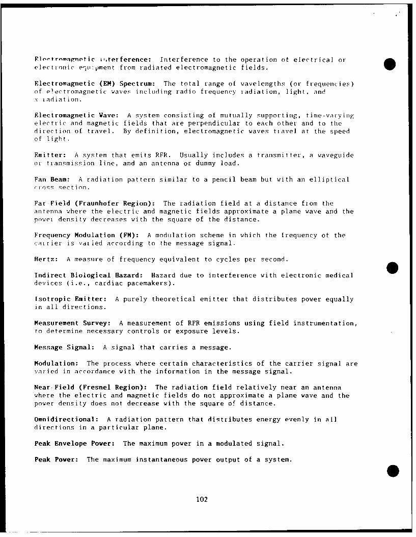
Flortrnmafnetic i,,terference: Interference to the operation of electrical or
electronic e'1,vpment from radiated electromagnetic fields.
Electromagnetic (EM) Spectrum: The total range of wavelengths (or frequencies)of electromagnetic waves including radio frequency radiation, light, andx-iadiation.
Electromagnetic Wave: A system consisting of mutually supporting, time-varyingelectric and magnetic fields that are perpendicular to each other and to thedirection of travel. By definition, electromagnetic waves ttavel at the speed
of light.
Emitter: A system that emits RFR. Usually includes a transmitter, a waveguideor transmission line, and an antenna or dummy load.
Fan Beam: A radiation pattern similar to a pencil beam but with an ellipticalrross section.
Far-Field (Fraunhofer Region): The radiation field at a distance from theantenna where the electric and magnetic fields approximate a plane wave and thepower density decreases with the square of the distance.
Frequency Modulation (FM): A modulation scheme in which the frequency of thecarrier is vdied according to the message signal.
Hertz: A measure of frequency equivalent to cycles per second. 0Indirect Biological Hazard: Hazard due to interference with electronic medicaldevices (i.e., cardiac pacemakers).
Isotropic Emitter: A purely theoretical emitter that distributes power equallyin all directions.
Measurement Survey: A measurement of RFR emissions using field instrumentation,
to determine necessary controls or exposure levels.
Message Signal: A signal that carries a message.
Modulation: The process where certain characteristics of the carrier signal arevaried in accordance with the information in the message signal.
Near-Field (Fresnel Region): The radiation field relatively near an antennawhere the electric and magnetic fields do not approximate a plane wave and thepower density does not decrease with the square of distance.
Omnidirectional: A radiation pattern that distributes energy evenly in alldirections in a particular plane.
Peak Envelope Power: The maximum power in a modulated signal.
Peak Power: The maximum instantaneous power output of a system.
0102
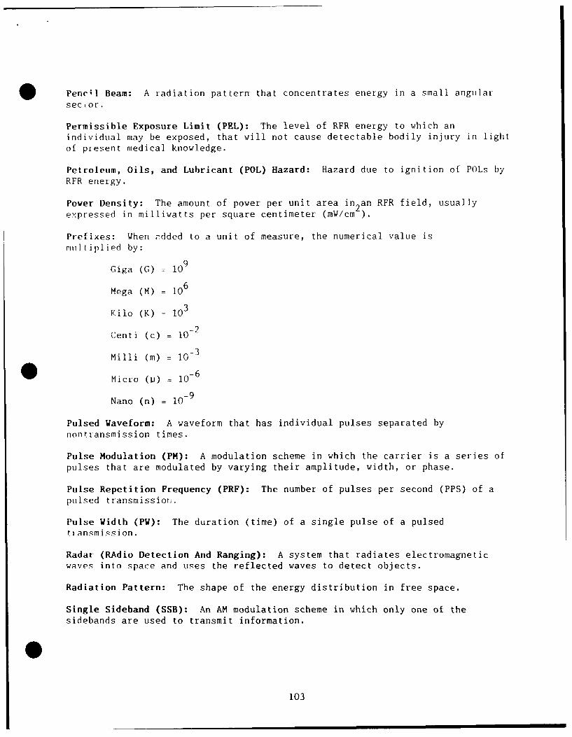
Penc;l Beam: A radiation pattern that concentrates energy in a small angularsector.
Permissible Exposure Limit (PEL): The level of RFR energy to which anindividual may be exposed, that will not cause detectable bodily injury in lightof present medical knowledge.
Petroleum, Oils, and Luhricant (POL) Hazard: Hazard due to ignition of POLs byRFR energy.
Power Density: The amount of power per unit area in 2an RFR field, usuallyexpressed in milliwatts per square centimeter (mW/cm ).
Prefixes: When added to a unit of measure, the numerical value ismultiplied by:
Giga (G) = 109
Mega (M) = 106
Kilo (K) = 103
Centi (c) = 102
Milli (m) = 10- 3
Micro (p) = 10- 6
Nano (n) = 10- 9
Pulsed Waveform: A waveform that has individual pulses separated bynontransmission times.
Pulse Modulation (PH): A modulation scheme in which the carrier is a series ofpulses that are modulated by varying their amplitude, width, or phase.
Pulse Repetition Frequency (PRF): The number of pulses per second (PPS) of apulsed transmission.
Pulse Width (PW): The duration (time) of a single pulse of a pulsedtiansmission.
Radar (RAdio Detection And Ranging): A system that radiates electromagneticwaves into space and uses the reflected waves to detect objects.
Radiation Pattern: The shape of the energy distribution in free space.
Single Sideband (SSB): An AM modulation scheme in which only one of thesidebands are used to transmit information.
103
Site Inspection Survey: A visual inspection of an emitter site to determine iffurther controls or investigation are needed.
Suppressed Carrier: An AM modulation scheme (either DSB or SSB) in whic:h theoutput is zero when there is no message signal.
Thermal Effects: Biological effects caused directly by heating of the tissuec.
Transition Region: The region between the far-field and the near-field regionswhere the field has some characteristics of both.
Transmission Line: The part of an emitter that carries the signal from the
transmitter to the antenna.
Transmitter: Part of an emitter that generates and amplifies an RF signal.
Watt (W): A unit of power; equal to joules per second.
104
* DistributionCopies
HO AFSC/SGPB 2Andrews AFB DC 20334-5000
HO AAC/SGPB 2Elmendorf AFB AK 99506-5001
HO AU/SGPB 2
Maxwell AFB AL 36112-5304
HQ USAF Academy/SGPB 2
Colorado Springs CO 80840-5470
HO AFLC/SGBE 2Wright-Patterson AFB OH 45433-5001
1t0 ATC/SGPB 2Randolph AFB TX 78150-5001
HO USAF/SGPA 2
Bolling AFB DC 20332-6188
HQ TAC/SGPB 2
* Langley AFB VA 23665-5001
HO AFRES/SGB 2Robins AFB GA 31098-6001
HO MAC/SGPB 2Scott AFB IL 62225-5001
HO AFSPACECMD/SGB 2Peterson Field CO 80914-5001
HO SAC/SGPB 2Offutt AFB NE 68113-5001
[IQ AFISC/SGM 1Norton AFB CA 92409-7001
7100 Combat Support Wing/SGB 2APO New York 09220-5300
OL AD, AFOEHL 2APO San Francisco 96274-5000
HO PACAF/SGPB 2
Hickam AFB HI 96853-5001
O HQ USAFE/SGPA 2APO New York 09012-5000
105

HO ANGSC/SGB 2
Mailstop 18
Andrews AFB DC 20331-6008
USAFSAM/TSK 1
Brooks AFB TX 78235-5301
USAFSAM/EDH 1
Brooks AFB TX 78235-5301
HQ HSD/XAE 1
Brooks AFB TX 78235-5000
Defense Technical Information Center (DTIC) 2
Cameron Station
Alexandria VA 22304-6145
Each Bioenvironmental Engineering Section (including ANG and AFRES) 1
Each Environmental Health Section (including ANG and AFRES) 1
106
0 S GOVERNMENT PRIrITNG OFFICE 1989-661.041 00042