Embed Size (px)
Citation preview
1
Base Station Antenna Selection for
Low-Resolution ADC Systems
Jinseok Choi, Junmo Sung, Narayan Prasad, Xiao-Feng Qi,
Brian L. Evans, and Alan Gatherer
Abstract
This paper investigates antenna selection at a base station with large antenna arrays and low-
resolution analog-to-digital converters. For downlink transmit antenna selection for narrowband channels,
we show (1) a selection criterion that maximizes sum rate with zero-forcing precoding equivalent to that
of a perfect quantization system; (2) maximum sum rate increases with number of selected antennas;
(3) derivation of the sum rate loss function from using a subset of antennas; and (4) unlike high-
resolution converter systems, sum rate loss reaches a maximum at a point of total transmit power
and decreases beyond that point to converge to zero. For wideband orthogonal-frequency-division-
multiplexing (OFDM) systems, our results hold when entire subcarriers share a common subset of
antennas. For uplink receive antenna selection for narrowband channels, we (1) generalize a greedy
antenna selection criterion to capture tradeoffs between channel gain and quantization error; (2) propose
a quantization-aware fast antenna selection algorithm using the criterion; and (3) derive a lower bound
on sum rate achieved by the proposed algorithm based on submodular functions. For wideband OFDM
systems, we extend our algorithm and derive a lower bound on its sum rate. Simulation results validate
theoretical analyses and show increases in sum rate over conventional algorithms.
Index Terms
J. Choi, J. Sung, and B. L. Evans conducted this research in the Wireless Networking and Communications Group
(WNCG), Department of Electrical and Computer Engineering, The University of Texas at Austin, Austin, TX, USA. (e-
mail: {jinseokchoi89, junmo.sung}@utexas.edu, [email protected]). J. Sung is also currently with Samsung in Dallas, TX,
USA. N. Prasad and X. Qi are with the Radio Algorithms Research Group, Futurewei Technologies, NJ Research Center,
Bridgewater, NJ, USA. (email: {narayan.prasad, xiao.feng.qi}@futurewei.com). A. Gatherer is with Wireless Access Lab.,
Futurewei Technologies, Legacy Dr, Plano, TX, USA. (e-mail: [email protected]). The authors at The University
of Texas at Austin were supported by WNCG Industrial Affiliates Funding from Futurewei Technologies received in 2018. A
preliminary version of this work was presented at IEEE ICASSP 2018 [1].
arX
iv:1
907.
0048
2v1
[ee
ss.S
P] 3
0 Ju
n 20
19
2
Downlink and uplink antenna selection, low-resolution ADCs, OFDM communications, maximum
sum rate, greedy antenna selection,
I. INTRODUCTION
Large-scale multiple-input multiple-output (MIMO) systems have been considered as a poten-
tial technology for future wireless systems because they offer orders of magnitude improvement
in spectral efficiency [2], [3]. The large number of antennas, however, comes with practical
challenges such as hardware cost and power consumption [4]. Antenna selection can be a
potential solution to reduce the large power consumption by efficiently reducing the number
of radio frequency (RF) chains [5]. In addition, since the power consumption of analog-to-
digital converters (ADCs) scales exponentially in the number of quantization bits [6], reducing
the resolution of ADCs provides additional power savings for future communication systems [7],
[8]. In this regard, we investigate base station (BS) antenna selection problems in low-resolution
ADC systems for uplink (UL) and downlink (DL) communications.
A. Prior Work
Antenna selection problems have been widely studied without quantization error for high-
resolution ADC systems. For the transmit antenna selection, it was shown that single antenna
selection achieves full diversity gain which the transmitter without antenna selection (the trans-
mitter uses all antennas) achieves [9], and it is optimal in the low signal-to-noise ratio (SNR)
[10]. To find the best transmit antenna subset, convex optimization techniques were adopted
by relaxing a binary integer problem to a real number problem [11], [12]. Transmit antenna
selection was also jointly studied with other problems [13], [14]. An outage probability was
derived for single user selection and antenna selection in [13], and a precoder was designed
jointly with antenna selection [14]. Energy and spectral efficiency tradeoff was maximized in
[15] by solving a multi-objective antenna selection problem. For special systems such as spatial
modulation systems, a Euclidian distance-based antenna selection method was developed [16].
Receive antenna selection methods were also developed for last decade [17]–[22]. In [17], a
greedy antenna selection method was developed by minimizing capacity loss. It was shown in
[17] that the diversity order of the receive antennal selection system is same as the full diversity
order. In [18], a correlation-based method and mutual information-based method were developed,
showing that selecting receive antennas more than the number of transmit antennas can nearly
3
achieve the performance of full receive antenna systems. Convex optimization approach was also
taken in receive antenna selection [19]. To provide a lower bound of greedy selection methods,
modularity and submodularity concepts were used in [20]. In [23] a sampling-based selection
method was proposed by employing cross entropy optimization technique.
Antenna selection problems have been studied for various channels. For correlated channels,
selection algorithms were proposed by exploiting partial channel state information (CSI) such as a
channel covariance matrix [24]. Antenna selection problems were also solved for millimeter wave
channels jointly with precoder design [25], [26]. In orthogonal frequency division multiplexing
(OFDM) systems, both transmit antenna selection [27], [28] and receive antenna selection
algorithms [21], [22] were developed. An adaptive Markov chain Monte Carlo (MCMC) method
was adopted for antenna selection [21], and optimal power allocation between training and
data symbols with antenna selection was derived to minimize performance loss due to channel
estimation error [22]. An outage probability was analyzed for per-subcarrier antenna selection
in [27], and an adaptive antenna selection method that balances between per-subcarrier and bulk
selection was proposed in [28].
Most prior work on antenna selection, however, focused on MIMO systems without any
quantization errors. Accordingly, antenna selection for low-resolution ADC systems that incorpo-
rates coarse quantization effect needs to be investigated. In [29], a cross entropy maximization
approach in [23] was extended for low-resolution ADC systems by jointly solving the user
scheduling problem. Transmit antenna selection was analyzed for single antenna selection by
utilizing Weibul distribution in low-resolution ADC systems [30]. In [30], it was shown that
although the TAS gain is limited when compared to the gain for perfect quantization, the TAS
gain can still provide a large increase of ergodic rate. Although the proposed receive antenna
selection algorithm in [29] demonstrated its high performance, it can require high complexity
when the number of candidate antennas are large due to its parameters such as the number
of iterations and sampling. In addition, the transmit antenna selection in [30] considers single
antenna selection and thus, it is difficult to be generalized to multiple antenna selection.
B. Contributions
In this paper, we extend our previous work [1] to investigate antenna selection at a BS with a
large number of antenna arrays in low-resolution ADC systems where both the BS and mobile
4
stations (MSs) are equipped with low-resolution ADCs. We investigate DL transmit antenna
selection and UL receive antenna selection. The contributions are summarized as follows:
• For narrowband channels, we show that the DL transmit antenna selection problem with
zero-forcing (ZF) precoding in low-resolution ADC systems is equivalent to that in high-
resolution ADC systems when antennas are selected to maximize the DL sum rate. Observing
the quantization effect in the SNR, we further analyze the DL sum rate with antenna selection
by incorporating quantization effects. We show that selecting more transmit antennas provides
larger maximum sum rate for low-resolution ADC systems as well as high-resolution ADC
systems. Unlike the rate loss in high-resolution ADC systems, we prove that the rate loss
decreases beyond a certain point of transmit power and converges to zero in low-resolution
ADC systems.
• For an UL receive antenna selection problem in the narrowband, we generalize an existing
criterion for a greedy capacity-maximization antenna selection method to incorporate quantiza-
tion effects. The derived objective function offers an opportunity to select an antenna with the
best tradeoff between the additional channel gain and increase in quantization error. We also
derive a lower bound of the sum rate achieved by the proposed greedy algorithm by using a
concept of submodularity. In addition, we modify the adaptive MCMC antenna selection [21]
for the low-resolution ADC systems to provide a numerical upper bound of the sum rate.
• We extend the antenna selection problem to the wideband OFDM systems. We first derive the
wideband OFDM systems under coarse quantization for both DL and UL communications.
Then, we show that the derived results in the DL narrowband communications also hold for
the DL OFDM communication when subcarriers share a common antenna subset. For the UL
OFDM communications, we modify the proposed received antenna selection algorithms and
derive the lower bound of the capacity with the greedy algorithm.
• Simulation results validate the theoretical results and demonstrate that the proposed algorithm
outperforms conventional algorithms in achievable rate. The proposed receive antenna selection
algorithm provides near optimal sum rate performance in the large antenna array regime.
Notation: A is a matrix and a is a column vector. AH and AT denote conjugate transpose and
transpose. [A]i,: and ai indicate the ith row and column vector of A. We denote ai,j or [A]i,j as
the {i, j}th element of A and ai as the ith element of a. CN (µ, σ2) is the circularly complex
Gaussian distribution with mean µ and variance σ2. E[·] and V[·] represent an expectation and
5
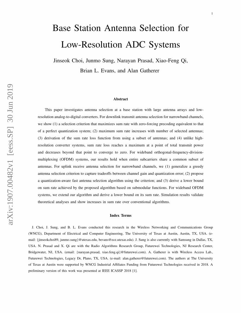
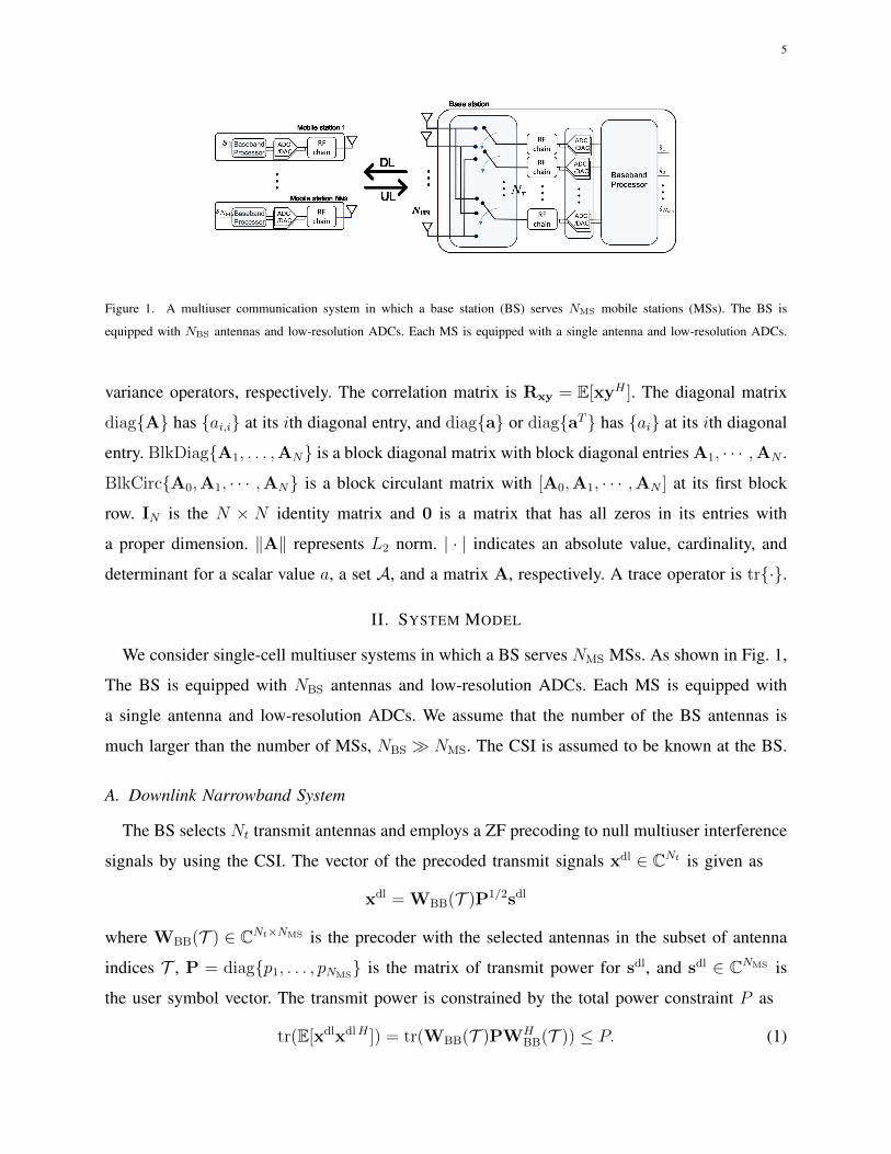
Figure 1. A multiuser communication system in which a base station (BS) serves NMS mobile stations (MSs). The BS is
equipped with NBS antennas and low-resolution ADCs. Each MS is equipped with a single antenna and low-resolution ADCs.
variance operators, respectively. The correlation matrix is Rxy = E[xyH ]. The diagonal matrix
diag{A} has {ai,i} at its ith diagonal entry, and diag{a} or diag{aT} has {ai} at its ith diagonal
entry. BlkDiag{A1, . . . ,AN} is a block diagonal matrix with block diagonal entries A1, · · · ,AN .
BlkCirc{A0,A1, · · · ,AN} is a block circulant matrix with [A0,A1, · · · ,AN ] at its first block
row. IN is the N × N identity matrix and 0 is a matrix that has all zeros in its entries with
a proper dimension. ‖A‖ represents L2 norm. | · | indicates an absolute value, cardinality, and
determinant for a scalar value a, a set A, and a matrix A, respectively. A trace operator is tr{·}.
II. SYSTEM MODEL
We consider single-cell multiuser systems in which a BS serves NMS MSs. As shown in Fig. 1,
The BS is equipped with NBS antennas and low-resolution ADCs. Each MS is equipped with
a single antenna and low-resolution ADCs. We assume that the number of the BS antennas is
much larger than the number of MSs, NBS � NMS. The CSI is assumed to be known at the BS.
A. Downlink Narrowband System
The BS selects Nt transmit antennas and employs a ZF precoding to null multiuser interference
signals by using the CSI. The vector of the precoded transmit signals xdl ∈ CNt is given as
xdl = WBB(T )P1/2sdl
where WBB(T ) ∈ CNt×NMS is the precoder with the selected antennas in the subset of antenna
indices T , P = diag{p1, . . . , pNMS} is the matrix of transmit power for sdl, and sdl ∈ CNMS is
the user symbol vector. The transmit power is constrained by the total power constraint P as
tr(E[xdlxdlH ]) = tr(WBB(T )PWHBB(T )) ≤ P. (1)
6
With ZF precoding, the precoder WBB(T ) becomes WBB(T ) = HdlHT (Hdl
THdlHT )−1. Accord-
ingly, the vector of received analog baseband signals at the MSs is given as
rdl = HdlT x
dl + ndl = P1/2sdl + ndl (2)
where HdlT ∈ CNMS×Nt is the DL narrowband channel matrix, which consists of Nt selected
columns of the DL channel Hdl ∈ CNMS×NBS , and ndl ∼ CN (0, INMS) is the additive white
circularly complex Gaussian noise (AWGN) vector.
Using the additive quantization noise model (AQNM) [31], which provides a reasonable
accuracy for low to medium SNR [32], the quantized DL received signal vector is expressed as
ydl = Q(Re{rdl}
)+ jQ
(Im{rdl}
)= αbP
1/2sdl + αbndl + qdl (3)
where Q(·) is the element-wise quantizer function. Here, αb is defined as αb = 1 − βb and
considered to be the quantization gain (αb < 1), and βb is the normalized mean squared
quantization error βb = E[|ri−yi|2]E[|ri|2]
. Assuming a scalar minimum mean squared error (MMSE)
quantizer and Gaussian signaling sdl ∼ CN (0, INMS), βb is approximated as βb ≈ π
√3
22−2b
for b > 5 [33], where b is the number of quantization bits for each real and imaginary part.
The values of βb for b ≤ 5 are shown in Table 1 in [34]. The vector qdl ∈ CNMS represents
the additive quantization noise that is uncorrelated with the quantization input rdl [31]. We
assume that the quantization noise follows the complex Gaussian distribution with a zero mean
qdl ∼ CN (0,Rqdlqdl) [34]. The covariance matrix of qdl is derived as [34]
Rqdlqdl = αb(1− αb)diag{E[rdlrdlH
]}= αb(1− αb)(P + INMS
). (4)
B. Uplink Narrowband System
The BS selects Nr receive antennas and receives signals from NMS MSs. The selected antennas
are connected to RF chains followed by low-resolution ADCs. The UL narrowband channel
matrix between the BS and MSs is denoted as Hul ∈ CNBS×NMS . The received baseband analog
signals at the Nr selected antennas rul ∈ CNr can be expressed as
rul =√ρHulKs
ul + nul (5)
where ρ, HulK ∈ CNr×NMS , sul ∈ CNMS , and nul ∈ CNr denotes the transmit power, the channel
matrix for the selected antennas in the subset of antenna indices K, the user symbol vector, and
the AWGN vector, respectively. We assume sul ∼ CN (0, INMS) and nul ∼ CN (0, INr).
7
After the antenna selection, each real and imaginary component of the complex output ruli ,
where ruli denotes the ith element of rul in (5), is quantized at the pair of ADCs. Adopting the
AQNM [31], the quantized UL received baseband signals becomes
yul = Q(Re{rul}
)+ jQ
(Im{rul}
)= αb
√ρHulKs
ul + αbnul + qul (6)
where qul represents the additive quantization noise that is uncorrelated with rul. We assume
qul ∼ CN (0,Rqulqul) [34]. The covariance matrix of qul is given by
Rqulqul = αb(1− αb) diag(ρHulKH
ulHK + INr). (7)
In the following sections, we explore antenna selection for the considered DL and UL systems.
III. DOWNLINK TRANSMIT ANTENNA SELECTION
In this section, we first show that a transmit antenna selection problem with ZF precoding
for narrowband channels in low-resolution ADC systems is equivalent to that in high-resolution
ADC systems. The resulting achievable rate, however, involves the quantization error and thus,
we analyze the sum rate in low-resolution ADC systems.
A. Sum Rate Maximization Problem
From the quantized signals ydl in (3) and quantization covariance matrix Rqdlqdl in (4), the
DL achievable rate for user i with selected transmit antennas in T becomes
γdli (T ) = log2
(1 +
α2bpi
α2b + αb(1− αb)(1 + pi)
). (8)
We consider an equal power distribution. Assuming equal power distribution, pi = pT , ∀i, and
ZF precoding with maximum transmit power from (1), we have
pT =P
tr(WH
BB(T )WBB(T )) =
P
tr((HTHH
T )−1) . (9)
Using (8) and (9), the DL achievable sum rate reduces to
Rdl(T ) = NMS log2
(1 +
αbpT1 + (1− αb)pT
). (10)
8
We now formulate the transmit antennas selection problem by adopting the achievable sum rate
in (10) as an objective function. Let S = {1, 2, . . . , NBS} be the index set of the BS antennas.
Then, the transmit antenna selection problem for maximum sum rate is formulated as
P1 : T ? = argmaxT ⊆S:NMS≤|T |≤Nt
Rdl(T ).
where Nt is the given maximal number of transmit antennas that can be selected.
Remark 1. The transmit antenna selection problem P1 with ZF precoding and equal power
allocation for narrowband channels is equivalent to that in high-resolution ADC systems.
Accordingly, we show that any state-of-the-art transmit antenna selection methods for multiuser
communications with the ZF precoding [12], [35] can be applicable in low-resolution ADC
systems. The achievable rate Rdl(T ), however, includes the quantization effect as a noise that
is proportional to the transmit power, which differs from perfect quantization systems. In this
regards, we provide theoretical analysis for the transmit antenna selection problem to characterize
the sum rate and draw intuitions for the low-resolution ADC regime in the following subsection.
B. Sum Rate Analysis of Transmit Antenna Selection
Here, we first derive a property of the sum rate in the considered low-resolution ADC system
with respect to the number of selected antennas. To this end, we introduce Lemma 1.
Lemma 1. For any matrix H ∈ Cm×n with rank(H) = m, the following inequality holds:
tr(QH̃(I` − H̃HQH̃)−1H̃HQ
)> 0
where Q = (τIm + HHH)−1 with τ ≥ 0 and H̃ is a m× ` sub-matrix of H which consists of
the columns of H for 1 ≤ ` ≤ (n−m).
Proof. See Lemma 2 in [35]. �
Theorem 1. The maximum sum rate of MSs with low-resolution ADCs in (10) is monotonically
increasing with the number of selected transmit antennas in ZF precoding DL systems (2):
Rdl(T opt1) < Rdl(T opt2)
where T opt1 and T opt2 are the optimal antenna subsets with |T opt1| < |T opt2|.
9
Proof. Let T 1 and T 2 be antenna subsets with T 1 ⊂ T 2 ⊆ S, and T̄ be T̄ = T 2 − T 1. The
average sum rate difference between the sum rates with the two antenna subsets, T 1 and T 2, is
RdlD(T̄ )
NMS
=Rdl(T 2)−Rdl(T 1)
NMS
= log2
(1 +
αbpT21 + (1− αb)pT2
)− log2
(1 +
αbpT11 + (1− αb)pT1
). (11)
Using pTi = P/tr((HdlTiH
dlHTi )−1) for i = 1, 2, we rewrite (11) as
RdlD(T̄ )
NMS
= log2
((tr((Hdl
T2HdlHT2 )−1) + P )(tr((Hdl
T1HdlHT1 )−1) + (1− αb)P )
(tr((HdlT2H
dlHT2 )−1) + (1− αb)P )(tr((Hdl
T1HdlHT1 )−1) + P )
).
Let Q = (HdlT2H
dlHT2 )−1 and ΨΨΨT̄ = QHdl
T̄ (I|T̄ | − HdlHT̄ QHdl
T̄ )−1HdlHT̄ Q. Then, leveraging the
matrix inversion lemma, the rate difference RdlD(T̄ ), which we also call as the rate loss, becomes
RdlD(T̄ ) =NMS log2
((tr(Q) + P )(tr(Q) + tr(ΨΨΨT̄ ) + (1− αb)P )
(tr(Q) + (1− αb)P )(tr(Q) + tr(ΨΨΨT̄ ) + P )
)=NMS log2
(1 +
αbtr(ΨΨΨT̄ )P
tr(Q)2 +(tr(ΨΨΨT̄ ) + P
)tr(Q) + (1− αb)
(P 2 + P (tr(ΨΨΨT̄ ) + tr(Q))
)) (12)
(a)> 0 (13)
where (a) holds from the following reasons: we have tr(Q) > 0, and from Lemma 1 with τ = 0,
we have tr(ΨΨΨT̄ ) > 0 for any channel matrix HdlT2 with rank(Hdl
T2) = NMS and its NMS × |T̄ |
sub-matrix HdlT̄ with 1 ≤ |T̄ | ≤ (|T2| −NMS). In addition, αb is always less than one (αb < 1)
since it is the quantization gain defined as αb = 1− E[|ri − yi|2]/E[|ri|2].
Now, let T 2 be the antenna subset that satisfies T opt1 ⊂ T 2 and |T opt1| < |T 2| = |T opt2|.
Then, we obtain the following inequalities:
Rdl(T opt1) < Rdl(T 2) ≤ Rdl(T opt2)
where Rdl(T opt1) < Rdl(T 2) follows from leveraging RdlD(T̄ ) > 0 in (12) and Rdl(T 2) ≤
Rdl(T opt2) comes from the optimality definition of T opt2. This completes the proof. �
Although adding more transmit antennas is not guaranteed to increase the sum rate [20] in
general because of a transmit power constraint, Theorem 1 shows that the maximum sum rate
increases with the number of selected transmit antennas Nt even with the coarse quantization at
the user mobile. This result was also shown to be true for high-resolution ADC systems [35].
Now we will show that the sum rate loss RdlD(T̄ ) has a different property compared to the
high-resolution ADC systems where the loss monotonically increases with P and converges to
10
an upper bound [35]. Having T 2 = S, RdlD(T̄ ) can be considered as the sum rate loss due to
antennas selection and minimized to zero by increasing the transmit power constraint P .
Corollary 1. Let T 1 ⊂ T 2 ⊆ S, then the achievable sum rate loss RdlD(T̄ ) = Rdl(T 2)−Rdl(T 1)
goes to zero under coarse quantization as the transmit power constraint P increases
RdlD(T̄ )→ 0 as P →∞.
In addition, the achievable rate converges to Rdl(T )→ NMS log2
(1 + αb
1−αb
)as P →∞.
Proof. If P → ∞, the achievable sum rate loss in (12) goes to zero and the sum rate in (10)
converges to NMS log2
(1 + αb
1−αb
). �
Unlike the high-resolution ADC system, this result suggests that antenna selection can have
the marginal rate loss from the system using the entire antennas by increasing P .
Corollary 2. Let T 1 ⊂ T 2 ⊆ S. Then, the transmit power constraint that leads to the maximum
sum rate loss from not using antennas in T̄ = T 2 − T 1 is
PmaxD =
√tr(Q)tr(K)
1− αb(14)
where Q = (HdlT2H
dlHT2 )−1 and K = (Hdl
T1HdlHT1 )−1, and the maximum sum rate loss is
Rdl,maxD (T̄ ) = NMS log2
(1 +
αb(tr(K)− tr(Q)
)tr(Q) + (1− αb)tr(K) + 2
√(1− αb)tr(Q)tr(K)
). (15)
Proof. Let Q = (HdlT2H
dlHT2 )−1 and ΨΨΨT̄ = QHdl
T̄ (I|T̄ | −HdlHT̄ QHdl
T̄ )−1HdlHT̄ Q. The derivative of
(12) with respect to the transmit power constraint is derived as
dRdlD(T̄ )
dP=αbNMStr(ΨΨΨT̄ )
(tr(Q)2 + tr(Q)tr(ΨΨΨT̄ ) + (αb − 1)P 2
)ΓT̄
(16)
where ΓT̄ = ln 2(tr(Q)+P )(tr(Q)+tr(ΨΨΨT̄ )+P )(tr(Q)+(1−αb)P )(tr(Q)+tr(ΨΨΨT̄ )+(1−αb)P ).
Since 0 < αb < 1 and tr(ΨΨΨT̄ ) > 0, by setting (16) to be zero, we derive PmaxD as
PmaxD =
√tr(Q)2 + tr(Q)tr(ΨΨΨT̄ )
1− αb. (17)
Using tr((HdlT1H
dlHT1 )−1
)= tr(Q) + tr(ΨΨΨT̄ ), the maximizer Pmax
D (17) is rewritten as (14). With
respect to the transmit power constraint P , the maximum sum rate loss for T 1 and T 2 can be
determined by putting P = PmaxD into (13), which leads to (15). This completes the proof. �
11
According to Corollary 2, the transmit antenna selection in low-resolution ADC systems always
achieves the sum rate with the rate loss less than Rdl,maxD (T̄ ) in (15) for a selected antenna subset.
Note that if there is no quantization error, i.e., αb = 1, PmaxD goes to infinity. Then, the sum rate
loss cannot decrease with P in the perfect quantization system, which corresponds to the upper
bound of the sum rate loss in [35]. Since ΓT̄ and tr(ΨΨΨT̄ ) are positive, ∂RdlD(T̄ )/∂P in (16)
becomes positive when P < PmaxD and negative when P > Pmax
D , i.e., for P < PmaxD , the sum
rate loss increases as P increases, and for P > PmaxD , the loss decreases to zero as P increases.
Therefore, (14) can be considered as the reference power constraint that is required to reduce
the sum rate loss while achieving a reasonable sum rate.
Corollary 3. The maximum rate loss in low-resolution ADC systems is less than that in high-
resolution ADC systems, i.e., Rdl,maxD (T̄ ; b) ≤ Rdl,max
D (T̄ ;∞).
Proof. Since tr(ΨΨΨT̄ ) = tr(K) − tr(Q) > 0 from Lemma 1, where Q = (HdlT2H
dlHT2 )−1, K =
(HdlT1H
dlHT1 )−1, and ΨΨΨT̄ = QHdl
T̄ (I|T̄ | −HdlHT̄ QHdl
T̄ )−1HdlHT̄ Q, the maximum rate loss in (15) is
a monotonically increasing function with respect to αb with 0 < αb < 1. When αb → 1, the
considered system becomes equivalent to the high-resolution ADC system. �
Based on Corollary 3, the transmit antenna selection can be more effective in low-resolution
ADC systems as the rate loss is smaller than that in high-resolution ADC systems.
IV. UPLINK RECEIVE ANTENNA SELECTION
In this section, we examine the key difference of the receive antenna selection problem at the
BS with low-resolution ADCs from the conventional problem and propose a quantization-aware
receive antenna selection method.
A. Capacity Maximization Problem
For the considered UL narrowband system in (6), the capacity can be expressed as
Rul(K) = log2
∣∣∣INr + ρα2b
(α2bINr + Rqulqul
)−1HulKH
ulHK
∣∣∣ (18)
where Rqulqul is given in (7). We note from (18) that in the low-resolution ADC system, the
capacity involves the quantization noise covariance matrix Rqulqul as a penalty term for each
antenna. We use fHi to indicate the ith row of Hul and K(i) to denote the ith selected antenna.
12
Remark 2. Since each diagonal entry of Rqulqul contains an aggregated channel gains at each
selected antenna ‖fK(i)‖2, the tradeoff between the channel gain from adding antennas and its
influence on quantization error needs to be considered in antenna selection.
Using the capacity in (18), we formulate the UL receive antenna selection problem as follows:
P2 : K? = argmaxK⊆S:|K|=Nr≥NMS
Rul(K), (19)
where S = {1, . . . , NBS}. Notice that the large number of BS antennas NBS makes it almost
infeasible to perform an exhaustive search. Accordingly, to avoid searching over all possible
antenna subsets K, we propose two algorithms: a quantization-aware antenna selection algorithm
based on the greedy approach and a Markov chain Monte Carlo (MCMC)-based algorithm.
B. Greedy Approach
Now, let DK = diag{1+ρ(1−αb)‖fK(i)‖2} be the diagonal matrix with (1+ρ(1−αb)‖fK(i)‖2)
for i = 1, . . . , Nr at its diagonal entries. Then, the capacity in (18) can be rewritten as
Rul(K) = log2
∣∣∣INr + ραbD−1K Hul
KHulHK
∣∣∣. (20)
Let Kt be the set of selected antennas during the first t greedy selections and HKt∪{j} be the
channel matrix of t selected antennas during the first t greedy selections and a candidate antenna
j ∈ S \ Kt at the next selection stage. Then, we formulate the greedy selection problem as
J = argmaxj∈S\Kt
Rul(Kt ∪ {j}). (21)
To reduce the complexity of solving the problem in (21), we decompose the capacity formula
(20). At the (t+ 1)th selection stage with a candidate antenna j, we have
Rul(Kt ∪ {j}) = log2
∣∣∣INr + ραbD−1Kt∪{j}H
ulKt∪{j}H
ulHKt∪{j}
∣∣∣= log2
∣∣∣∣INMS+ ραb
(HulHKt D−1
KtHulKt+
1
djfjf
Hj
)∣∣∣∣. (22)
Recall that fHj denotes the jth row of Hul and dj is the corresponding diagonal entry of DKt∪{j}.
Using the matrix determinant lemma |A + uvH | = |A|(1 + vHA−1u), we rewrite (22) as
Rul(Kt ∪ {j}) = Rul(Kt) + log2
(1+
ραbdj
ct(j)
)(23)
where
ct(j) = fHj
(INMS
+ραbHulHKt D−1
KtHulKt
)−1
fj. (24)
13
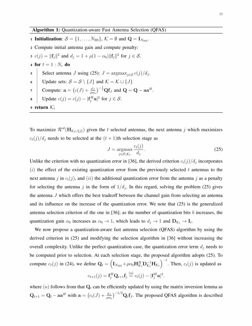
Algorithm 1: Quantization-aware Fast Antenna Selection (QFAS)
1 Initialization: S = {1, . . . , NBS}, K = ∅ and Q = INMS.
2 Compute initial antenna gain and compute penalty:
3 c(j) = ‖fj‖2 and dj = 1 + ρ(1− αb)‖fj‖2 for j ∈ S.
4 for t = 1 : Nr do
5 Select antenna J using (25): J = argmaxj∈S c(j)/dj .
6 Update sets: S = S \ {J} and K = K ∪ {J}
7 Compute: a =(c(J) + dJ
ραb
)− 12QfJ and Q = Q− aaH .
8 Update c(j) = c(j)− |fHj a|2 for j ∈ S.
9 return K;
To maximize Rul(HKt∪{j}) given the t selected antennas, the next antenna j which maximizes
ct(j)/dj needs to be selected at the (t+ 1)th selection stage as
J = argmaxj∈S\Kt
ct(j)
dj. (25)
Unlike the criterion with no quantization error in [36], the derived criterion ct(j)/dj incorporates
(i) the effect of the existing quantization error from the previously selected t antennas to the
next antenna j in ct(j), and (ii) the additional quantization error from the antenna j as a penalty
for selecting the antenna j in the form of 1/dj . In this regard, solving the problem (25) gives
the antenna J which offers the best tradeoff between the channel gain from selecting an antenna
and its influence on the increase of the quantization error. We note that (25) is the generalized
antenna selection criterion of the one in [36]; as the number of quantization bits b increases, the
quantization gain αb increases as αb → 1, which leads to dj → 1 and DKt → It.
We now propose a quantization-aware fast antenna selection (QFAS) algorithm by using the
derived criterion in (25) and modifying the selection algorithm in [36] without increasing the
overall complexity. Unlike the perfect quantization case, the quantization error term dj needs to
be computed prior to selection. At each selection stage, the proposed algorithm adopts (25). To
compute ct(j) in (24), we define Qt =(INMS
+ραbHHKtD
−1KtHKt
)−1
. Then, ct(j) is updated as
ct+1(j) = fHj Qt+1fj(a)= ct(j)− |fHj a|2.
where (a) follows from that Qt can be efficiently updated by using the matrix inversion lemma as
Qt+1 = Qt− aaH with a =(ct(J) + dJ
ραb
)−1/2QtfJ . The proposed QFAS algorithm is described
14
in Algorithm 1. Note that the complexity for step 5 and 6 are O(NrN2MS) and O(NrNMSNBS),
respectively. The overall complexity becomes O(NrNMSNBS) because of (NBS � NMS). Thus,
the proposed algorithm does not increase the overall complexity from the conventional algorithm
[36], which provides the opportunity to be practically implemented.
Now, we analyze the performance of the proposed QFAS method by using submodularity.
Definition 1 (Submodularity). If V is a finite set, a submodular function is a set function f :
2V → R which meets the following condition: for every A,B ⊆ V with A ⊆ B and every element
v ∈ V \ B, f satisfies that f(A ∪ {v})− f(A) ≥ f(B ∪ {v})− f(B).
Definition 2 (Monotone). A set function f : 2V → R is monotone if for every A ⊆ B ⊆ V , we
have that f(A) ≤ f(B). f is said to be normalized if f(φ) = 0, where φ denotes the empty set.
From the definition of a submodular set function, it exhibits a diminishing return property.
The following theorem provides a performance lower bound of greedy methods for optimizing
submodular objective functions.
Theorem 2 ([37]). For a normalized nonnegative and monotone submodular function f : 2V →
R+, letAG ⊆ V be a set with |AG| = k obtained by selecting elements one at a time and choosing
an element that provides the largest marginal increase in the function value at each time. Let A?
be the optimal set that maximizes the value of f with |A?| = k. Then, f(AG) ≥ (1− 1e)f(A?).
Based on Theorem 2, it was shown in [20] that the achievable rate of a point-to-point MIMO
system is a submodular function, and hence, the greedy antenna selection algorithm for high-
resolution ADC systems provides at least(1− 1
e
)Ropt, where Ropt the achievable rate with the
optimal antenna subset for high-resolution ADC systems. We extend this result to the capacity
with the quantization error in (18).
Corollary 4. The capacity achieved by the proposed QFAS method is lower bounded by
Rul(Kqfas) ≥(
1− 1
e
)Rul(K?). (26)
Proof. We first need to show that the achievable rate with the quantization error Rul(K) in (18)
is submodular. Let ΓΓΓK = INr + ρα2b
(α2bINr + Rqulqul
)−1/2HulKH
ulHK(α2bINr + Rqulqul
)−1/2. Let
15
xK ∼ CN (0,ΓΓΓK). Since ΓΓΓK is nonsingular, the entropy of xK is given as
h(xK) = ln |πeΓΓΓK| = Nr ln(πe) +1
log2 eRul(K).
Exploiting the form of Rqul,qul in (7), for any sets A ⊆ B ⊆ S and element such that {s} /∈ B and
{s} ∈ S , we have h(x{s}|xA) ≥ h(x{s}|xB), i.e., h(xA∪{s})− h(xA) ≥ h(xB∪{s})− h(xB). The
entropy is submodular and Rul(K) in (18) is also submodular. In addition, Rul(K) is normalized
and monotone. Since Rul(K) (18) is submodular, monotone, and nonnegative, the capacity with
the greedy maximization in (21) is lower bounded by (26) from Theorem 2. Thus, the capacity
with the proposed QFAS is also lower bounded by (26). �
C. Markov Chain Monte Carlo Approach
To find a numerical upper bound of the capacity for the antenna selection without exhaustive
search, we provide an algorithm that finds an approximated optimal solution for the problem
P2 in (19). We modify the adaptive MCMC-based selection method [21] by adopting (18)
for formulating an original probability density function (PDF). To develop the MCMC-based
algorithm for low-resolution ADC systems, we define a binary vector ωωω ∈ {0, 1}NBS with ‖ωωω‖0 =
Nr where 1 indicates that the corresponding receive antenna is selected and vice versa. Here, ωωω
can be considered as a codeword of the codebook V that contains all possible combinations of
antenna subsets of size Nr, i.e., |V| =(NBS
Nr
). Now, let the original PDF be
π(ωωω) , exp
(1
τRul(ωωω)
)/Γ (27)
where τ is a rate constant and Γ is a normalizing factor. We reformulate P2 in (19) as
ωωω? = argmaxωωω∈V
π(ωωω). (28)
To solve (28), the proposed algorithm uses a Metropolized independence sampler (MIS) [38]
for the MCMC sampling, which is performed as follows: for a given current sample ωωω(i), a
new sample ωωωnew is selected according to a proposal distribution q(ωωω). Based on a accepting
probability paccept(π, q) = min{1, π(ωωωnew)π(ωωω(i))
q(ωωω(i))q(ωωωnew)
}, we obtain a next sample as ωωω(i + 1) = ωωωnew
if accepted, or we have ωωω(i + 1) = ωωω(i), otherwise. After NMCMC iterations, we have a set of
(1 +NMCMC) samples including an initial sample ωωω(0), i.e., {ωωω(0),ωωω(1), . . . ,ωωω(NMCMC)}.
For the proposal distribution, we use the product of Bernoulli distributions which is given as
q(ωωω;p) =1
Γ′
NBS∏j=1
p[ωωωv ]jj (1− pj)1−[ωωωv ]j (29)
16
where pj represents the probability of receive antenna j to be selected and [ωωω]j denotes the jth
element of ωωω. Since Γ′ is unnecessary for computing the accepting probability paccept, we use
q(ωωω;p) without Γ′. Similarly, we also use π(ωωω) without the normalizing factor Γ for paccept.
The selection probabilities p will be adaptively updated at each iteration in the algorithm to
increase the similarity between π(ωωω) and q(ωωω;p). We update the probability entries pj to update
the proposal distribution q(ωωω;p) by minimizing the Kullback-Leibler divergence between π(ωωω)
and q(ωωω;p) [21]. Then, the update at (t+ 1)th iteration becomes
p(t+1)j = p
(t)j + r(t+1)
(1
NMCMC
NMCMC∑i=1
[ωωω(i)]j − p(t)j
)(30)
where r(t) is a sequence of decreasing step sizes that satisfies∑∞
t=0 r(t) =∞ and
∑∞t=0(r(t))2 <
∞ [39]. Finally, Algorithm 2 describes the quantization-aware MCMC-based antenna selection
(QMCMC-AS) algorithm. Algorithm 2 stops once it reaches a stopping criterion, which we set
as the number of maximum iterations τstop. The computational complexity of the QMCMC-AS
method is O(NrN2MSNMCMCτstop) [21]. We note that unlike the QFAS method, the complexity
of the QMCMC-AS method involves additional parameters such as the sample size NMCMC and
the number of iterations τstop. When(NBS
Nr
)is large, the QMCMC-AS method is required to have
large NMCMC and τstop to find a good subset of antennas [23]. Accordingly, the complexity of
the QMCMC-AS can be unnecessarily high. Thus, we use the QMCMC-AS method only to
provide an approximated optimal performance as a benchmark.
V. EXTENSION TO WIDEBAND CHANNELS
In this section, we derive the multiuser OFDM system models with quantization error and
extend the DL and UL antenna selection problems to the wideband OFDM system.
A. Downlink OFDM Communications
Let Nsc be the number of subcarriers for the OFDM system and un ∈ CNMS be the frequency
domain symbol vector of NMS MSs at the nth subcarrier after ZF precoding for the selected
antennas in T . We consider bulk selection where all subcarriers share a same antenna subset.
Then, un ∈ CNMS is given as
un = WBB,n(T )P1/2n sdl
n
17
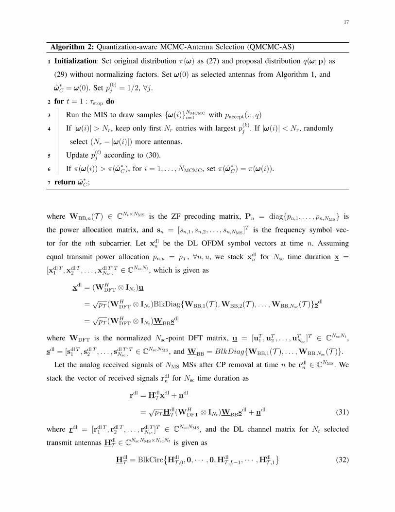
Algorithm 2: Quantization-aware MCMC-Antenna Selection (QMCMC-AS)
1 Initialization: Set original distribution π(ωωω) as (27) and proposal distribution q(ωωω;p) as
(29) without normalizing factors. Set ωωω(0) as selected antennas from Algorithm 1, and
ω̂ωω∗C = ωωω(0). Set p(0)j = 1/2, ∀j.
2 for t = 1 : τstop do
3 Run the MIS to draw samples {ωωω(i)}NMCMCi=1 with paccept(π, q)
4 If |ωωω(i)| > Nr, keep only first Nr entries with largest p(k)j . If |ωωω(i)| < Nr, randomly
select (Nr − |ωωω(i)|) more antennas.
5 Update p(t)j according to (30).
6 If π(ωωω(i)) > π(ω̂ωω∗C), for i = 1, . . . , NMCMC, set π(ω̂ωω∗C) = π(ωωω(i)).
7 return ω̂ωω∗C ;
where WBB,n(T ) ∈ CNt×NMS is the ZF precoding matrix, Pn = diag{pn,1, . . . , pn,NMS} is
the power allocation matrix, and sn = [sn,1, sn,2, . . . , sn,NMS]T is the frequency symbol vec-
tor for the nth subcarrier. Let xdln be the DL OFDM symbol vectors at time n. Assuming
equal transmit power allocation pn,u = pT , ∀n, u, we stack xdln for Nsc time duration x =
[xdlT1 ,xdlT
2 , . . . ,xdlTNsc
]T ∈ CNscNt , which is given as
xdl = (WHDFT ⊗ INt)u
=√pT (WH
DFT ⊗ INt)BlkDiag{WBB,1(T ),WBB,2(T ), . . . ,WBB,Nsc(T )}sdl
=√pT (WH
DFT ⊗ INt)WBBsdl
where WDFT is the normalized Nsc-point DFT matrix, u = [uT1 ,uT2 , . . . ,u
TNsc
]T ∈ CNscNt ,
sdl = [sdlT1 , sdlT
2 , . . . , sdlTNsc
]T ∈ CNscNMS , and WBB = BlkDiag{WBB,1(T ), . . . ,WBB,Nsc(T )}.
Let the analog received signals of NMS MSs after CP removal at time n be rdln ∈ CNMS . We
stack the vector of received signals rdln for Nsc time duration as
rdl = HdlT x
dl + ndl
=√pTH
dlT (WH
DFT ⊗ INt)WBBsdl + ndl (31)
where rdl = [rdlT1 , rdlT
2 , . . . , rdlTNsc
]T ∈ CNscNMS , and the DL channel matrix for Nt selected
transmit antennas HdlT ∈ CNscNMS×NscNt is given as
HdlT = BlkCirc
{HdlT ,0,0, · · · ,0,Hdl
T ,L−1, · · · ,HdlT ,1}
(32)
18
where HdlT ,` ∈ CNMS×Nt is the channel matrix of the selected antennas in T for the (` + 1)th
channel tap, L is the number of channel taps, and ndl = [ndlT1 ,ndlT
2 , . . . ,ndlTNsc
]T ∈ CNscNMS
denotes the vector of the AWGN noise vectors stacked for Nsc time duration.
The received OFDM signals rdl are quantized at the ADCs. The quantized signal are expressed
with the AQNM as [31]
ydl = αb√pTH
dlT (WH
DFT ⊗ INt)WBBsdl + αbn
dl + qdl
where qdl = [qdlT1 ,qdlT
2 , . . . ,qdlTNsc
]T ∈ CNscNMS is the additive quantization noise vector and
qdl ∼ CN (0,Rqdlqdl). Finally, the quantized signal is combined through a DFT matrix as
zdl = (WDFT ⊗ INMS)ydl
= αb√pT (WDFT ⊗ INMS
)HdlT (WH
DFT ⊗ INt)WBBsdl + (WDFT ⊗ INMS
)(αbndl + qdl)
= αb√pTG
dlTWBBs
dl + vdl
(a)= αb
√pT s
dl + vdl.
Here, GdlT = (WDFT ⊗ INMS
)HdlT (WH
DFT ⊗ INt) = BlkDiag{GdlT ,1, · · · ,Gdl
T ,Nsc} where Gdl
T ,n =∑L−1`=0 Hdl
T ,` e− j2π(n−1)`
Nsc is the frequency domain DL channel matrix for subcarrier n, and vdl =
(WDFT ⊗ INMS)(αbn
dl + qdl) = [vdlT1 , · · · ,vdlT
Nsc]T . The equality (a) follows from the ZF
precoding WBB = BlkDiag{WBB,1(T ), · · · ,WBB,Nsc(T )} = GdlHT (Gdl
TGdlHT )−1, i.e.,
WBB,n(T ) = GdlHT ,n (Gdl
T ,nGdlHT ,n )−1.
Under coarse quantization, the received digital signal after DFT for subcarrier n becomes
zdln = αb
√pT s
dln + vdl
n .
Now, we compute the covariance matrix of vdln . Let WMS = (WDFT ⊗ INMS
) and WBS =
(WDFT ⊗ INt). Then, the covariance matrix of vdln is expressed as
Rvdln vdl
n= α2
bWMS,nE[ndlndlH
]WH
MS,n + WMS,nE[qdlqdlH
]WH
MS,n
= α2bINMS
+ WMS,nRqdlqdlWHMS,n
where WMS,n = ([WDFT]n,:⊗ INMS), and Rqdlqdl = E
[qdlqdlH
]is the covariance matrix of qdl.
To derive Rqdlqdl , we first simplify the precoding matrix WBB as follows:
WBB = GdlHT (Gdl
TGdlHT )−1
(a)= WBSH
dlHT WH
MS
(WMSH
dlTW
HBSWBSH
dlHT WH
MS
)−1
(b)= WBSH
dlHT(HdlTH
dlHT)−1
W−1MS (33)
19
where (a) comes from the definition of GdlT = WMSH
dlTW
HBS and (b) follows from the fact that
WMS, WBS, and HdlTH
dlHT are invertible. Then, the covariance matrix of qdl becomes [31], [34]
Rqdlqdl = αb(1− αb)diag{E[rdlrdlH ]
}= αb(1− αb)diag
{pTH
dlTW
HBSWBBW
HBBWBSH
dlHT + INscNMS
}(a)= αb(1− αb)(pT + 1)INscNMS
(34)
where (a) follows from (33). Finally, using (34), the covariance matrix Rvdln vdl
nbecomes Rvdl
n vdln
=
(αb + αb(1− αb)pT )INMS. Accordingly, the SINR of user u for nth subcarrier is given as
SINRu,n(T ) =αbpT
1 + (1− αb)pT. (35)
Using (35), we formulate the transmit antenna selection problem for the OFDM system as
P3 : T ?ofdm = argmaxT ⊆S:|T |=Nt≥NMS
Rdl,ofdm(T )
where Rdl,ofdm(T ) = 1Nsc
∑Nsc
n=1
∑NMS
u=1 log2
(1+SINRu,n(T )
)is the average sum rate. From (35),
it can be shown that the achievable rate is equal for all u and n. Consequently, maximizing the
sum rate is equivalent to maximizing the SINR in (35), and we need to select transmit antennas
that maximize the transmit power pT . We consider that the total transmit power is constrained
by P as tr{E[xdlxdlH ]} ≤ P . Assuming equal power allocation for each user and subcarrier,
we have tr{E[xdlxdlH ]
}= pT tr
{WH
BSWBBWHBBWBS
}= pT tr
{(HdlTH
dlHT )−1
}and thus, the
power allocation pT with maximum transmit power is given as
pT =P
tr{
(HdlTH
dlHT )−1
} . (36)
Remark 3. The transmit power in (36) shows that the transmit antenna selection problem for
DL OFDM communications in low-resolution ADC systems with ZF precoding and equal power
allocation is equivalent to that in high-resolution ADC systems.
Accordingly, any state-of-the-art transmit antenna selection methods for high-resolution ADC
OFDM systems with ZF-precoding can be employed for low-resolution ADC OFDM systems,
which was also true for narrowband communications as shown in Section III. In addition, we
note that the analysis derived in Section III-B also holds for the DL OFDM systems.
20
Corollary 5. For the multiuser DL OFDM system with ZF precoding and equal power distribu-
tion in (31), the maximum achievable sum rate of MSs with low-resolution ADCs is monotonically
increasing with the number of selected transmit antennas:
Rdl,ofdm(T opt1) < Rdl,ofdm(T opt2)
where T opt1 and T opt2 are the optimal antenna subsets with |T opt1| < |T opt2|.
Proof. We replace HdlT in the proof of Theorem 1 with Hdl
T and follow the same proof. �
According to Corollary 5, we need to use as many antennas at the BS for DL OFDM systems
with ZF-precoding to maximize the achievable rate even with quantization error at the MSs.
B. Uplink ODFM Communications
Similarly to the DL OFDM system model with low-resolution ADCs derived in the previous
section, the UL ODFM system with low-resolution ADCs can be modeled as follows [40].
Let xuln ∈ CNMS be a vector of the OFDM symbols of NMS MSs at time n. Let xul =
[xulT1 ,xulT
2 , . . . ,xulTNsc
]T ∈ CNscNMS , which is given as
xul =√ρ(WH
DFT ⊗ INMS)sul
where sul = [sulT1 , sulT
2 , . . . , sulTNsc
]T ∈ CNscNMS and suln = [sul
n,1, suln,2, . . . , s
uln,NMS
]T .
Let the analog received signals at the BS with Nr selected antennas in K after CP removal
at time n be ruln ∈ CNr . We stack the vector of received signals rul
n for Nsc time duration as
rul = HulKx
ul + nul
=√ρHulK(WH
DFT ⊗ INMS)sul + nul
where rul = [rulT1 , rulT
2 , . . . , rulTNsc
]T ∈ CNscNr , and the UL channel matrix in the time domain for
Nr selected antennas HulK ∈ CNscNr×NscNMS is given as
HulK = BlkCirc
{HulK,0,0, · · · ,0,Hul
K,L−1, · · · ,HulK,1}
where HulK,` is the UL channel matrix of the selected antennas for the (` + 1)th channel tap, L
is the number of channel taps, and nul = [nulT1 ,nulT
2 , . . . ,nulTNsc
]T ∈ CNscNr denotes the vector
of the AWGN noise vectors.
After quantization, the quantized OFDM signals are expressed by adopting the AQNM as [31]
yul = αb√ρHulK(WH
DFT ⊗ INMS)sul + αbn
ul + qul
21
where qul = [qulT1 ,qulT
2 , . . . ,qulTNsc
]T ∈ CNscNr is the additive quantization noise vector and
quln ∼ CN (0,Rqul
n quln
). The covariance matrix Rquln qul
nis derived as [31]
Rquln qul
n= αb(1− αb)diag{E[rul
n rulHn ]}
= αb(1− αb)diag{ρBKB
HK + INr
}(37)
where BK = [HulK,0,0, · · · ,0,Hul
K,L−1, · · · ,HulK,1]. We note that Rqul
n quln
= Rqulmqul
m,∀n 6= m, i.e.,
Rquln qul
nis independent to subcarriers. Finally, yul is combined through a DFT matrix as
zul = (WDFT ⊗ INr)yul
= αb√ρ(WDFT ⊗ INr)H
ulK(WH
DFT ⊗ INMS)sul + (WDFT ⊗ INr)(αbn
ul + qul)
= αb√ρGulKs
ul + vul
where GulK = (WDFT ⊗ INr)H
ulK(WH
DFT ⊗ INMS) = BlkDiag{Gul
K,1, · · · ,GulK,Nsc}, Gul
K,n =∑L−1`=0 Hul
K,`e− j2π(n−1)`
Nsc , and vul = (WDFT⊗ INr)(αbnul +qul) = [vulT
1 , · · · ,vulTNsc
]T . Accordingly,
under coarse quantization, the received digital signal after DFT for subcarrier n becomes
zuln = αb
√ρGulK,ns
uln + vul
n . (38)
The covariance matrix of vuln is derived as Rvul
n vuln
= α2bINr + Rqul
n quln
where Rquln qul
nis defined
in (37). Using (38), the UL capacity for subcarrier n is derived as
Ruln (K) = log2
∣∣∣INr + ρα2b(α
2bINr + Rqul
n quln
)−1GulK,nG
ulHK,n
∣∣∣. (39)
Note that the capacity of the wideband OFDM system for each subcarrier in (39) shows similar
structure as that of the narrowband system in (18).
Since all subcarriers share a same subset of antennas, i.e., K is same for all subcarriers, the
maximization cannot be applied to each subcarrier separately. Accordingly, we need to find the
best subset of antennas K for the entire subcarriers, and the receive antenna selection problem
for the wideband UL OFDM system is formulated as
P4 : K?ofdm = argmaxK⊆S:|K|=Nr≥NMS
Nsc∑n=1
Ruln (K). (40)
To solve (40), we extend the greedy approach for the narrowband communications in Section IV.
We also show that the MCMC approach can be naturally adopted with modification.
22
Similarly to (21), let GulKt∪{j},n be the channel matrix of t selected antennas during the first
t greedy selections and a candidate antenna j ∈ S \ Kt at the next selection. Then, the greedy
maximization problem is formulated as
J = argmaxj∈S\Kt
Nsc∑n=1
Ruln (Kt ∪ {j}) . (41)
Now, we decompose (39). Let D̄Kt∪{j} = It+1 +ρ(1−αb)diag{BKt∪{j}BHKt∪{j}}. At the (t+1)th
selection stage, we have
Ruln (Kt ∪ {j}) = log2
∣∣∣INMS+ ραbG
ulHKt∪{j},nD̄
−1Kt∪{j}G
ulKt∪{j},n
∣∣∣= log2
∣∣∣∣INMS+ ραb
(GulHKt,nD̄
−1KtG
ulKt,n+
1
d̄jfn,jf
Hn,j
)∣∣∣∣= Rul
n (Kt) + log2
(1+
ραbdj
cn,t(j)
)(42)
where fHn,j is jth row of Guln , d̄j is the corresponding diagonal entry of D̄Kt∪{j}, and cn,t(j) is
cn,t(j) = fHn,j
(INMS
+ραbGulHKt,nD̄
−1KtG
ulKt,n
)−1
fn,j. (43)
With (42), the greedy maximization problem in (41) reduces to
J = argmaxj∈S\Kt
Nsc∑n=1
log2
(1 +
ραbdj
cn,t(j)
). (44)
Therefore, a greedy algorithm that is similar to Algorithm 1 can be used for (44). In addition,
let Qn,t = (INMS+ραbG
ulHKt,nD̄
−1KtG
ulKt,n)−1. Then, cn,t(j) in (43) can also be updated without
matrix inversion for each subcarrier as shown in Algorithm 1. Accordingly, the complexity of
the proposed QFAS algorithm for the UL OFDM system becomes O(NscNrNMSNBS).
Corollary 6. The capacity of the QFAS method for the UL OFDM system is lower bounded byNsc∑n=1
Ruln (Kqfas) ≥
(1− 1
e
) Nsc∑n=1
Ruln (K?ofdm) (45)
where K?ofdm is the optimal subset of receive antennas defined in (40).
Proof. The class of submodular functions is closed under nonnegative linear combinations, and
we showed that the capacity with the quantization error is submodular in the proof of Corollary 4.
Consequently, the sum capacity for all carrier frequencies in (40) is also submodular. Since the
proposed QFAS for the wideband OFDM system solves (44), which is equivalent to the greedy
maximization in (41), from Theorem 2, we derive (45). �
23
10 20 30 40 50 60
0
5
10
15
20
25
30
35
0 10 20 30 40 50 60 70
0
10
20
30
40
50
60
(a) (b)
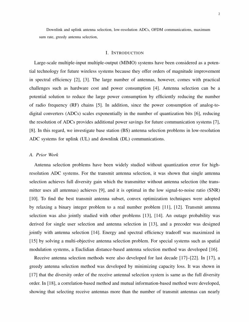
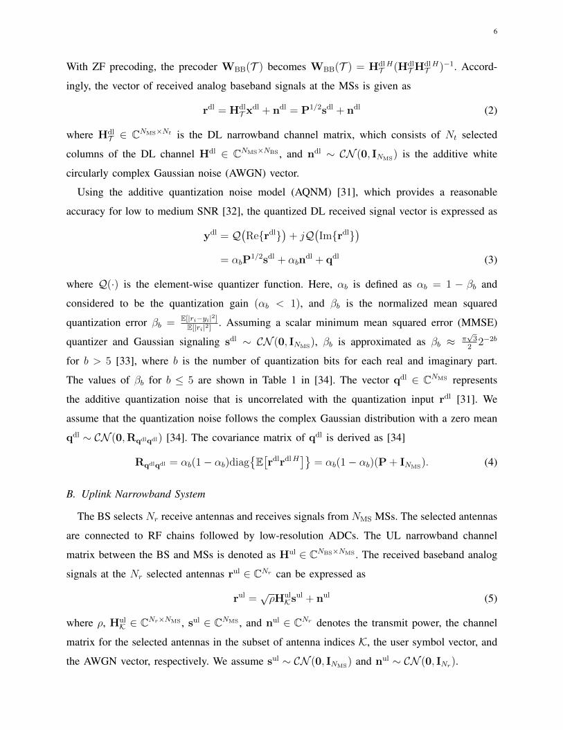
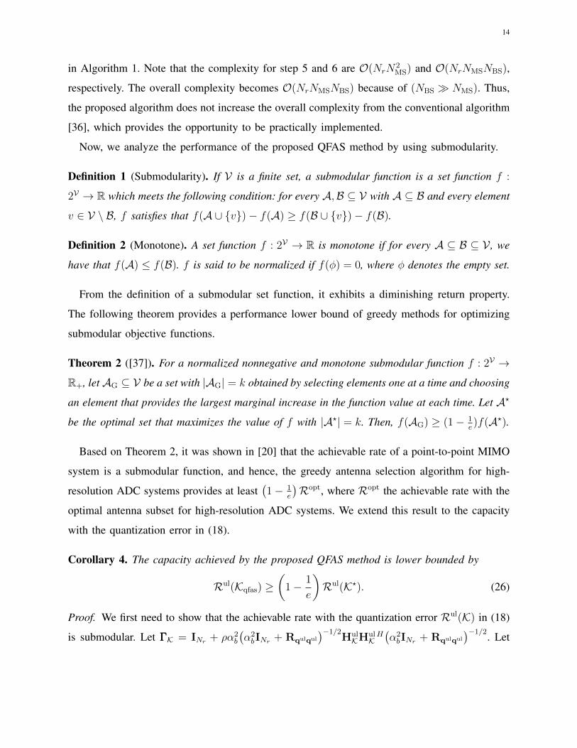
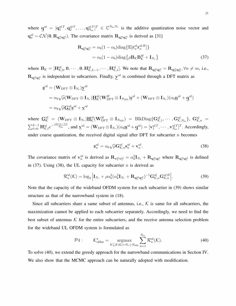
Figure 2. Average sum rate Rdl,ofdm (a) with respect to the number of selected antennas Nt for NBS = 64 BS antennas,
NMS = 8 MSs, P = 30 dBm total power constraint, and b ∈ {3, 4, 5} ADC bits, and (b) with respect to the total transmit
power constraint P for NBS = 128 BS antennas, NMS = 12 MSs, Nt = 16 selected antennas, and b = 3 ADC bits.
To find an approximated optimal solution, we can also use the adaptive MCMC approach
described in IV-C. To this end, the original PDF π(ωωω) needs to be modified as
π(ωωω) , exp
(1
τ
Nsc∑n=1
Ruln (ωωω)
)/Γofdm (46)
where τ is a rate constant and Γofdm is a normalizing factor for the PDF. Then, the adaptive
MCMC-based antenna selection method for the OFDM system can be performed similarly to
the QMCMC-AS method in IV-C. The complexity of the QMCMC-AS method for the OFDM
system is O(NscNrN2MSNMCMCτstop).
VI. SIMULATION RESULTS
In this section, we validate the theoretical results and proposed methods. We assume Rayleigh
channels with a zero mean and unit variance for small scale fading. For a large scale fading,
we adopt the log-distance pathloss model [41]. We consider randomly distributed MSs over a
single cell with radius of 1km. We assume the minimum distance between the BS and MSs to
be 100m. Considering a 2.4 GHz carrier frequency with 10 MHz bandwidth, we use 8.7 dB
lognormal shadowing variance and 12 dB noise figure at receivers.
24
0 5 10 15 20 25 30
12
14
16
18
20
22
24
26
-10 -5 0 5 10 15 20 25
10
15
20
25
30
35
40
45
(a) (b)
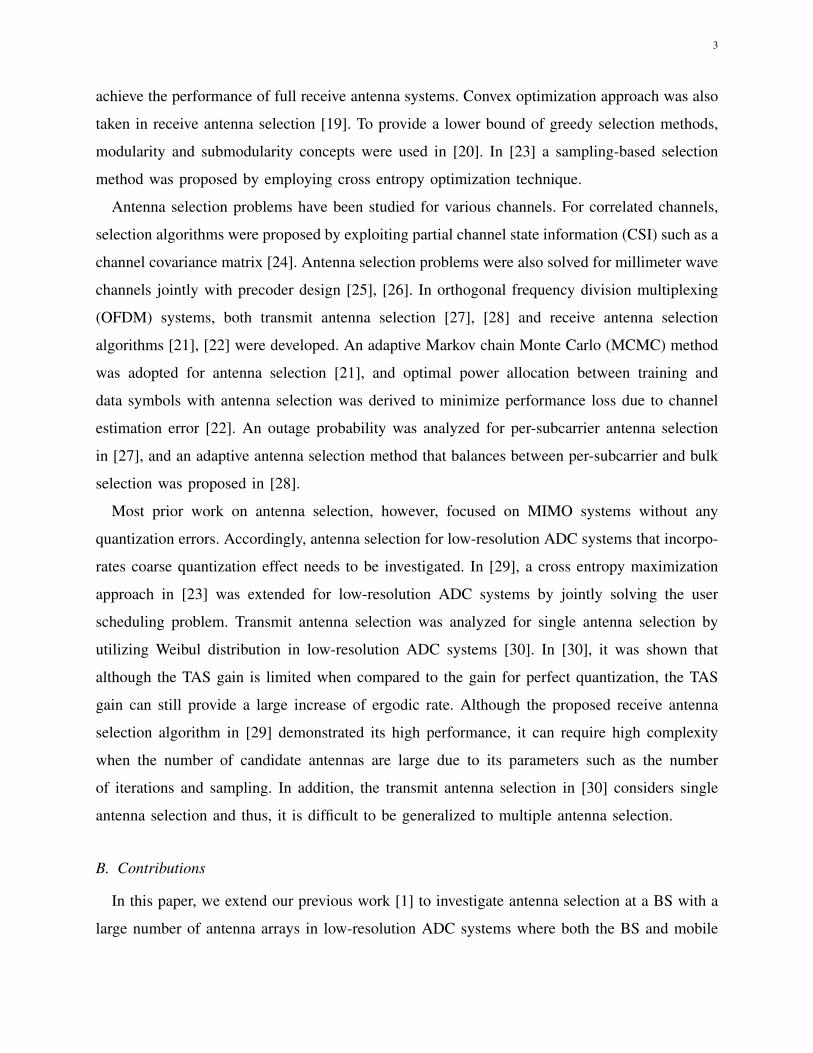
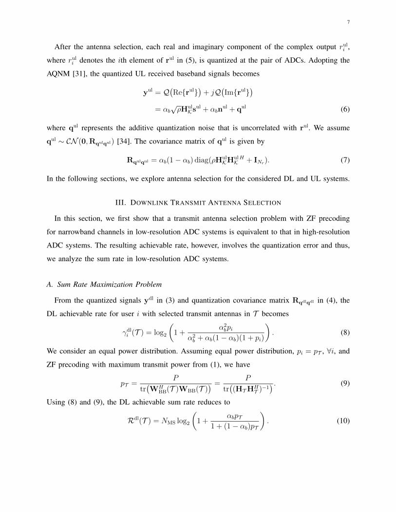
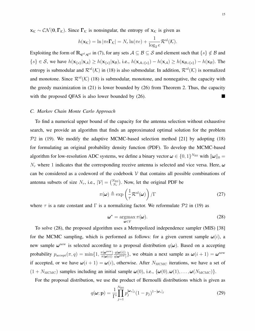
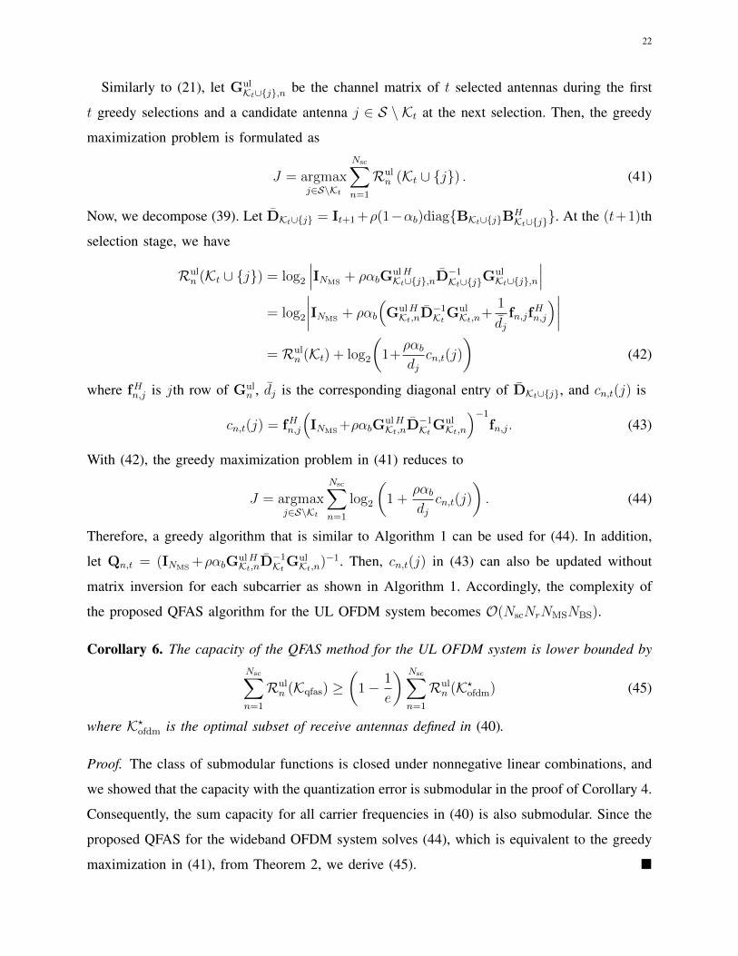
Figure 3. Average capacity Rul with respect to transmit power ρ for (a) NBS = 32 BS antennas, NMS = 8 MSs, Nr = 8
selected antennas, and b = 3 quantization bits, and for (b) NBS = 128 BS antennas, NMS = 12 MSs, Nr = 16 selected
antennas, and b = 3 ADC bits.
A. Downlink Transmit Antenna Selection
We consider the DL ODFM system with Nsc = 64 subcarriers for channels with L = 4 taps.
To validate the analysis, we use the norm-based selection (NBS) method in simulations, which
selects antennas in the order of channel norm that corresponds to each antenna [21], [23]. Note
that the NBS method always provides T 1 ⊆ T 2 when |T 1| ≤ |T 2| for the same channel. In
Fig. 2(a), the average sum rate increases with the number of selected antennas, which validates
the derived Theorem 1 and Corollary 5. Fig. 2(b) shows the average sum rate versus the total
power constraint P . Unlike the high-resolution ADC systems, there exists a point PmaxD for the
maximum rate loss from not using all antennas, and the rate loss decreases after the point PmaxD
in (14) for the OFDM channel Hdl. Theoretical PmaxD for the NBS method with Nt = 32 and
Nt = 16 are 33.1351 dBm and 37.2850, respectively. In addition, the theoretical maximum rate
loss in (15) for the OFDM channel Hdl with Nt = 32 and Nt = 16 are 19.8034 bps/Hz and
37.5282 bps/Hz, respectively, which also corresponds to the simulation results.
B. Uplink Receive Antenna Selection
We evaluate the proposed algorithms for the UL antenna selection—QFAS and QMCMC-AS
methods. We also simulate the NBS method [21], [23] and the fast antenna selection (FAS)
algorithm in [36], which shows a comparable performance to the optimal selection under perfect
25
2 3 4 5 6 7 8 9 10
10
15
20
25
30
35
40
45
50
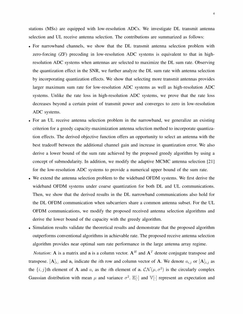
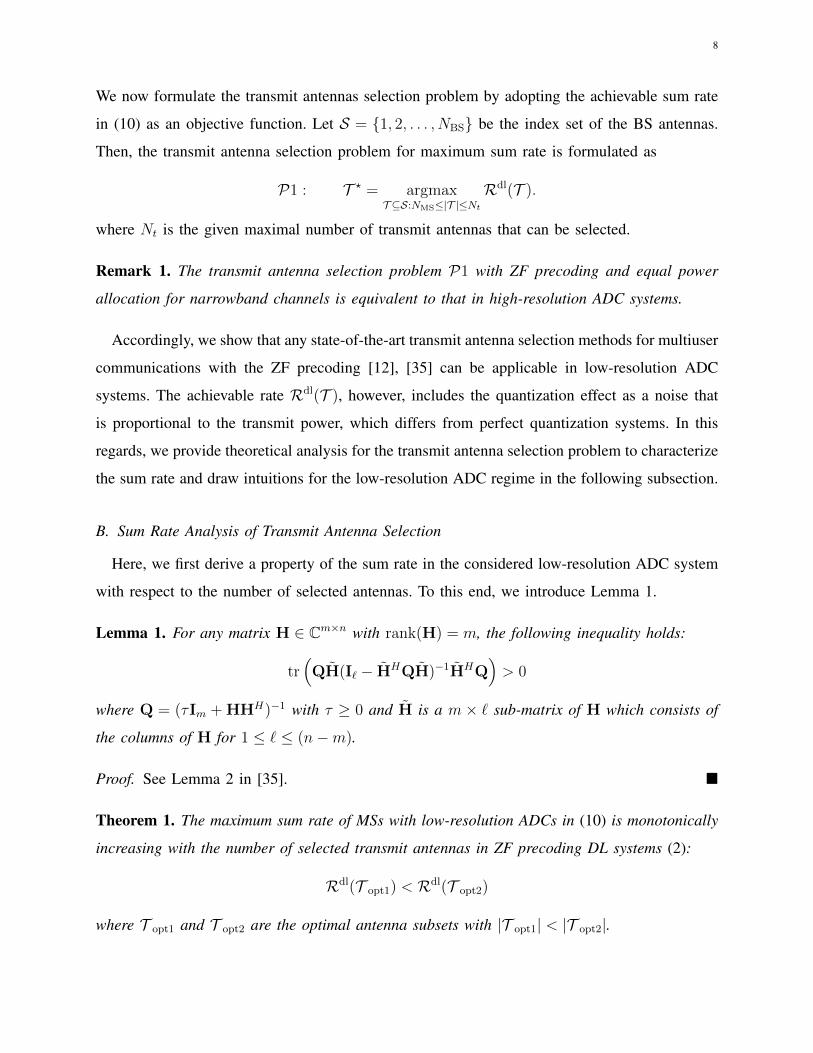
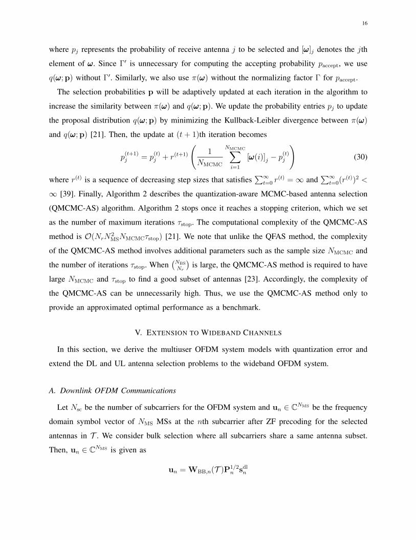
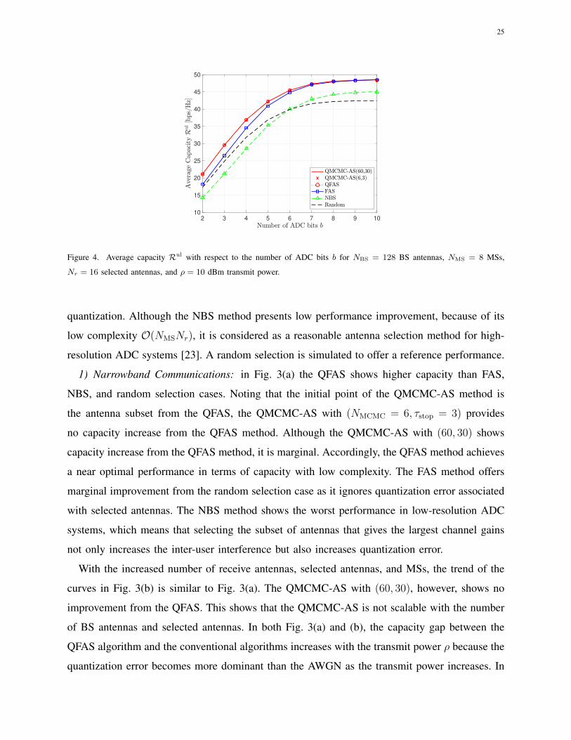
Figure 4. Average capacity Rul with respect to the number of ADC bits b for NBS = 128 BS antennas, NMS = 8 MSs,
Nr = 16 selected antennas, and ρ = 10 dBm transmit power.
quantization. Although the NBS method presents low performance improvement, because of its
low complexity O(NMSNr), it is considered as a reasonable antenna selection method for high-
resolution ADC systems [23]. A random selection is simulated to offer a reference performance.
1) Narrowband Communications: in Fig. 3(a) the QFAS shows higher capacity than FAS,
NBS, and random selection cases. Noting that the initial point of the QMCMC-AS method is
the antenna subset from the QFAS, the QMCMC-AS with (NMCMC = 6, τstop = 3) provides
no capacity increase from the QFAS method. Although the QMCMC-AS with (60, 30) shows
capacity increase from the QFAS method, it is marginal. Accordingly, the QFAS method achieves
a near optimal performance in terms of capacity with low complexity. The FAS method offers
marginal improvement from the random selection case as it ignores quantization error associated
with selected antennas. The NBS method shows the worst performance in low-resolution ADC
systems, which means that selecting the subset of antennas that gives the largest channel gains
not only increases the inter-user interference but also increases quantization error.
With the increased number of receive antennas, selected antennas, and MSs, the trend of the
curves in Fig. 3(b) is similar to Fig. 3(a). The QMCMC-AS with (60, 30), however, shows no
improvement from the QFAS. This shows that the QMCMC-AS is not scalable with the number
of BS antennas and selected antennas. In both Fig. 3(a) and (b), the capacity gap between the
QFAS algorithm and the conventional algorithms increases with the transmit power ρ because the
quantization error becomes more dominant than the AWGN as the transmit power increases. In
26
20 40 60 80 100 12024
26
28
30
32
34
36
38
40
42
QMCMC-AS(60,30)
QMCMC-AS(6,3)
QFAS
FAS
NBS
Random
2 4 6 8 10 12 14 16
10
15
20
25
30
35
40
45
(a) (b)
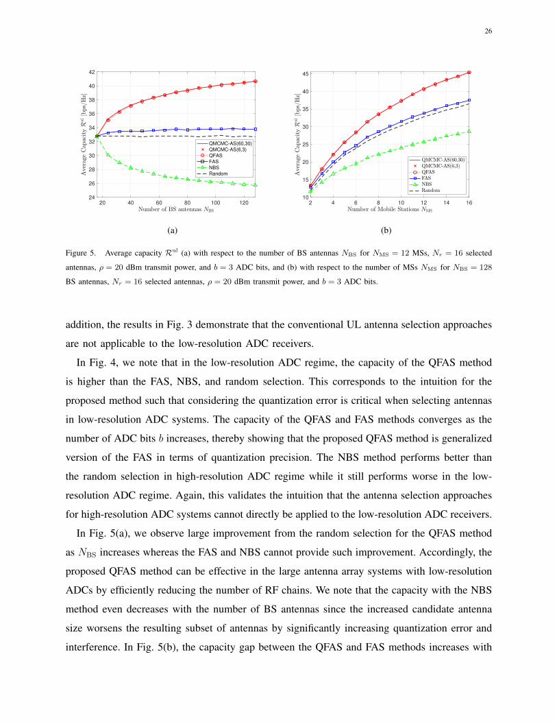
Figure 5. Average capacity Rul (a) with respect to the number of BS antennas NBS for NMS = 12 MSs, Nr = 16 selected
antennas, ρ = 20 dBm transmit power, and b = 3 ADC bits, and (b) with respect to the number of MSs NMS for NBS = 128
BS antennas, Nr = 16 selected antennas, ρ = 20 dBm transmit power, and b = 3 ADC bits.
addition, the results in Fig. 3 demonstrate that the conventional UL antenna selection approaches
are not applicable to the low-resolution ADC receivers.
In Fig. 4, we note that in the low-resolution ADC regime, the capacity of the QFAS method
is higher than the FAS, NBS, and random selection. This corresponds to the intuition for the
proposed method such that considering the quantization error is critical when selecting antennas
in low-resolution ADC systems. The capacity of the QFAS and FAS methods converges as the
number of ADC bits b increases, thereby showing that the proposed QFAS method is generalized
version of the FAS in terms of quantization precision. The NBS method performs better than
the random selection in high-resolution ADC regime while it still performs worse in the low-
resolution ADC regime. Again, this validates the intuition that the antenna selection approaches
for high-resolution ADC systems cannot directly be applied to the low-resolution ADC receivers.
In Fig. 5(a), we observe large improvement from the random selection for the QFAS method
as NBS increases whereas the FAS and NBS cannot provide such improvement. Accordingly, the
proposed QFAS method can be effective in the large antenna array systems with low-resolution
ADCs by efficiently reducing the number of RF chains. We note that the capacity with the NBS
method even decreases with the number of BS antennas since the increased candidate antenna
size worsens the resulting subset of antennas by significantly increasing quantization error and
interference. In Fig. 5(b), the capacity gap between the QFAS and FAS methods increases with
27
-5 0 5 10 15 20 25
12
13
14
15
16
17
18
19
20
21
22
23
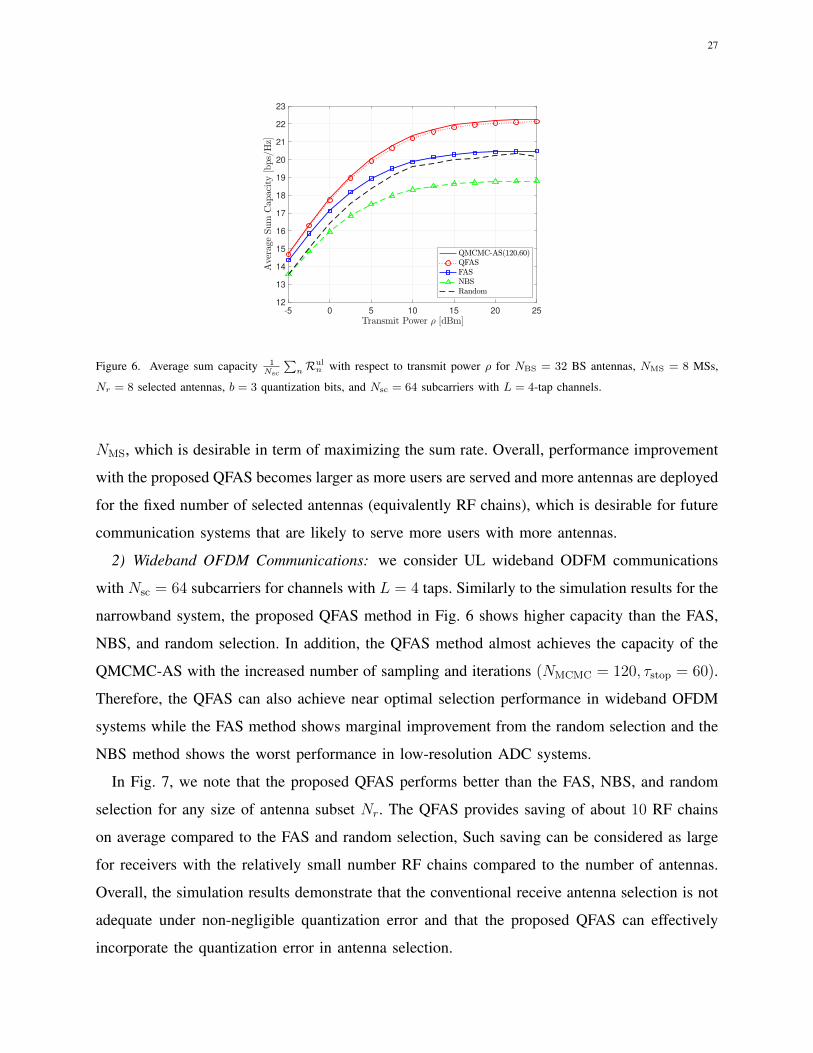
Figure 6. Average sum capacity 1Nsc
∑nR
uln with respect to transmit power ρ for NBS = 32 BS antennas, NMS = 8 MSs,
Nr = 8 selected antennas, b = 3 quantization bits, and Nsc = 64 subcarriers with L = 4-tap channels.
NMS, which is desirable in term of maximizing the sum rate. Overall, performance improvement
with the proposed QFAS becomes larger as more users are served and more antennas are deployed
for the fixed number of selected antennas (equivalently RF chains), which is desirable for future
communication systems that are likely to serve more users with more antennas.
2) Wideband OFDM Communications: we consider UL wideband ODFM communications
with Nsc = 64 subcarriers for channels with L = 4 taps. Similarly to the simulation results for the
narrowband system, the proposed QFAS method in Fig. 6 shows higher capacity than the FAS,
NBS, and random selection. In addition, the QFAS method almost achieves the capacity of the
QMCMC-AS with the increased number of sampling and iterations (NMCMC = 120, τstop = 60).
Therefore, the QFAS can also achieve near optimal selection performance in wideband OFDM
systems while the FAS method shows marginal improvement from the random selection and the
NBS method shows the worst performance in low-resolution ADC systems.
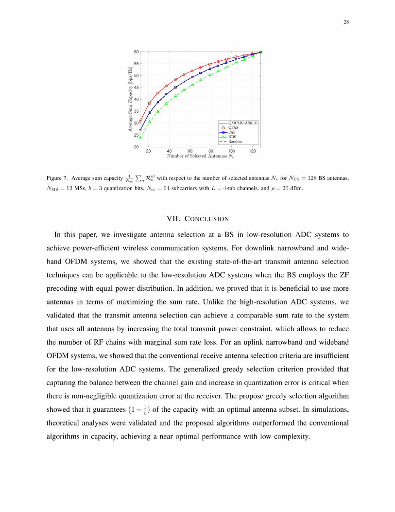
In Fig. 7, we note that the proposed QFAS performs better than the FAS, NBS, and random
selection for any size of antenna subset Nr. The QFAS provides saving of about 10 RF chains
on average compared to the FAS and random selection, Such saving can be considered as large
for receivers with the relatively small number RF chains compared to the number of antennas.
Overall, the simulation results demonstrate that the conventional receive antenna selection is not
adequate under non-negligible quantization error and that the proposed QFAS can effectively
incorporate the quantization error in antenna selection.
28
20 40 60 80 100 120
20
25
30
35
40
45
50
55
60
Figure 7. Average sum capacity 1Nsc
∑nR
uln with respect to the number of selected antennas Nr for NBS = 128 BS antennas,
NMS = 12 MSs, b = 3 quantization bits, Nsc = 64 subcarriers with L = 4-tab channels, and ρ = 20 dBm.
VII. CONCLUSION
In this paper, we investigate antenna selection at a BS in low-resolution ADC systems to
achieve power-efficient wireless communication systems. For downlink narrowband and wide-
band OFDM systems, we showed that the existing state-of-the-art transmit antenna selection
techniques can be applicable to the low-resolution ADC systems when the BS employs the ZF
precoding with equal power distribution. In addition, we proved that it is beneficial to use more
antennas in terms of maximizing the sum rate. Unlike the high-resolution ADC systems, we
validated that the transmit antenna selection can achieve a comparable sum rate to the system
that uses all antennas by increasing the total transmit power constraint, which allows to reduce
the number of RF chains with marginal sum rate loss. For an uplink narrowband and wideband
OFDM systems, we showed that the conventional receive antenna selection criteria are insufficient
for the low-resolution ADC systems. The generalized greedy selection criterion provided that
capturing the balance between the channel gain and increase in quantization error is critical when
there is non-negligible quantization error at the receiver. The propose greedy selection algorithm
showed that it guarantees (1− 1e) of the capacity with an optimal antenna subset. In simulations,
theoretical analyses were validated and the proposed algorithms outperformed the conventional
algorithms in capacity, achieving a near optimal performance with low complexity.
29
REFERENCES
[1] J. Choi, J. Sung, B. L. Evans, and A. Gatherer, “Antenna selection for large-scale MIMO systems with low-resolution
ADCs,” in IEEE Int. Conf. on Acoustics, Speech and Signal Process., Apr. 2018, pp. 3594–3598.
[2] T. L. Marzetta, “Noncooperative cellular wireless with unlimited numbers of base station antennas,” IEEE Trans. on
Wireless Commun., vol. 9, no. 11, p. 3590, Nov. 2010.
[3] E. G. Larsson, O. Edfors, F. Tufvesson, and T. L. Marzetta, “Massive MIMO for next generation wireless systems,” IEEE
Comm. Mag., vol. 52, no. 2, pp. 186–195, Feb. 2014.
[4] L. Lu, G. Y. Li, A. L. Swindlehurst, A. Ashikhmin, and R. Zhang, “An overview of massive MIMO: benefits and challenges,”
IEEE Journal of Sel. Topics in Signal Process., vol. 8, no. 5, pp. 742–758, Oct. 2014.
[5] R. Méndez-Rial, C. Rusu, N. González-Prelcic, A. Alkhateeb, and R. W. Heath, “Hybrid MIMO architectures for millimeter
wave Communications: Phase shifters or switches?” IEEE Access, vol. 4, pp. 247–267, Jan. 2016.
[6] R. H. Walden, “Analog-to-digital converter survey and analysis,” IEEE Journal on Sel. Areas in Commun., vol. 17, no. 4,
pp. 539–550, Apr. 1999.
[7] A. Mezghani and J. A. Nossek, “On ultra-wideband MIMO systems with 1-bit quantized outputs: Performance analysis
and input optimization,” in IEEE Int. Symposium on Inform. Theory, Jul. 2007, pp. 1286–1289.
[8] J. Mo and R. W. Heath, “Capacity analysis of one-bit quantized MIMO systems with transmitter channel state information,”
IEEE Trans. on Signal Process., vol. 63, no. 20, pp. 5498–5512, Oct. 2015.
[9] Z. Chen, J. Yuan, and B. Vucetic, “Analysis of transmit antenna selection/maximal-ratio combining in Rayleigh fading
channels,” IEEE Trans. on Veh. Technol., vol. 54, no. 4, pp. 1312–1321, Jul. 2005.
[10] S. Sanayei and A. Nosratinia, “Capacity of MIMO Channels With Antenna Selection,” IEEE Trans. on Inform. Theory,
vol. 53, no. 11, pp. 4356–4362, Nov. 2007.
[11] X. Gao, O. Edfors, J. Liu, and F. Tufvesson, “Antenna selection in measured massive MIMO channels using convex
optimization,” in IEEE Global Commun. Conf. Workshops, Dec. 2013, pp. 129–134.
[12] S. Khademi, E. DeCorte, G. Leus, and A. van der Veen, “Convex optimization for joint zero-forcing and antenna selection
in multiuser MISO systems,” in IEEE Int. Workshop on Signal Process. Adv. in Wireless Commun., Jun. 2014, pp. 30–34.
[13] X. Zhang, Z. Lv, and W. Wang, “Performance analysis of multiuser diversity in MIMO systems with antenna selection,”
IEEE Trans. on Wireless Commun., vol. 7, no. 1, pp. 15–21, Jan. 2008.
[14] P. V. Amadori and C. Masouros, “Large Scale Antenna Selection and Precoding for Interference Exploitation,” IEEE Trans.
on Commun., vol. 65, no. 10, pp. 4529–4542, Oct. 2017.
[15] Z. Liu, W. Du, and D. Sun, “Energy and Spectral Efficiency Tradeoff for Massive MIMO Systems With Transmit Antenna
Selection,” IEEE Trans. on Veh. Technol., vol. 66, no. 5, pp. 4453–4457, May 2017.
[16] P. Yang, Y. Xiao, Y. L. Guan, S. Li, and L. Hanzo, “Transmit Antenna Selection for Multiple-Input Multiple-Output Spatial
Modulation Systems,” IEEE Trans. on Commun., vol. 64, no. 5, pp. 2035–2048, May 2016.
[17] A. Gorokhov, D. A. Gore, and A. J. Paulraj, “Receive antenna selection for MIMO spatial multiplexing: theory and
algorithms,” IEEE Trans. on Signal Process., vol. 51, no. 11, pp. 2796–2807, Dec. 2003.
[18] A. F. Molisch, M. Z. Win, , and J. H. Winters, “Capacity of MIMO systems with antenna selection,” IEEE Trans. on
Wireless Commun., vol. 4, no. 4, pp. 1759–1772, July 2005.
[19] A. Dua, K. Medepalli, and A. J. Paulraj, “Receive antenna selection in MIMO systems using convex optimization,” IEEE
Trans. on Wireless Commun., vol. 5, no. 9, pp. 2353–2357, Sep. 2006.
[20] R. Vaze and H. Ganapathy, “Sub-Modularity and Antenna Selection in MIMO Systems,” IEEE Commun. Lett., vol. 16,
no. 9, pp. 1446–1449, Sep. 2012.
30
[21] Y. Liu, Y. Zhang, C. Ji, W. Q. Malik, and D. J. Edwards, “A low-complexity receive-antenna-selection algorithm for
MIMO–OFDM wireless systems,” IEEE Trans. on Veh. Technol., vol. 58, no. 6, pp. 2793–2802, Dec. 2009.
[22] A. B. Narasimhamurthy and C. Tepedelenlioglu, “Antenna Selection for MIMO-OFDM Systems With Channel Estimation
Error,” IEEE Trans. on Veh. Technol., vol. 58, no. 5, pp. 2269–2278, Jun 2009.
[23] Y. Zhang, C. Ji, W. Q. Malik, D. C. O’Brien, and D. J. Edwards, “Receive antenna selection for MIMO systems over
correlated fading channels,” IEEE Trans. on Wireless Commun., vol. 8, no. 9, pp. 4393–4399, Sep. 2009.
[24] L. Dai, S. Sfar, and K. B. Letaief, “Optimal antenna selection based on capacity maximization for MIMO systems in
correlated channels,” IEEE Trans. on Commun., vol. 54, no. 3, pp. 563–573, Mar. 2006.
[25] P. V. Amadori and C. Masouros, “Low RF-complexity millimeter-wave beamspace-MIMO systems by beam selection,”
IEEE Trans. on Commun., vol. 63, no. 6, pp. 2212–2223, May 2015.
[26] H. Li, Q. Liu, Z. Wang, and M. Li, “Joint Antenna Selection and Analog Precoder Design With Low-Resolution Phase
Shifters,” IEEE Trans. on Veh. Technol., vol. 68, no. 1, pp. 967–971, Jan 2019.
[27] M. Torabi, “Antenna selection for MIMO-OFDM systems,” Elsevier Signal Process., vol. 88, no. 10, pp. 2431–2441, 2008.
[28] N. P. Le, F. Safaei, and L. C. Tran, “Antenna Selection Strategies for MIMO-OFDM Wireless Systems: An Energy
Efficiency Perspective,” IEEE Trans. on Veh. Technol., vol. 65, no. 4, pp. 2048–2062, April 2016.
[29] J.-C. Chen, “Joint Antenna Selection and User Scheduling for Massive Multiuser MIMO Systems With Low-Resolution
ADCs,” IEEE Trans. on Veh. Technol., vol. 68, no. 1, pp. 1019–1024, Nov. 2019.
[30] J. Choi and B. L. Evans, “Analysis of Ergodic Rate for Transmit Antenna Selection in Low-Resolution ADC Systems,”
IEEE Trans. on Veh. Technol., vol. 68, no. 1, pp. 952–956, Oct. 2019.
[31] A. K. Fletcher, S. Rangan, V. K. Goyal, and K. Ramchandran, “Robust predictive quantization: Analysis and design via
convex optimization,” IEEE Journal of Sel. Topics in Signal Process., vol. 1, no. 4, pp. 618–632, Dec. 2007.
[32] O. Orhan, E. Erkip, and S. Rangan, “Low power analog-to-digital conversion in millimeter wave systems: Impact of
resolution and bandwidth on performance,” in IEEE Inform. Theory and App. Work., Feb. 2015, pp. 191–198.
[33] A. Gersho and R. M. Gray, Vector quantization and signal compression. Springer 2012 (originally published 1992).
[34] L. Fan, S. Jin, C.-K. Wen, and H. Zhang, “Uplink achievable rate for massive MIMO systems with low-resolution ADC,”
IEEE Commun. Lett., vol. 19, no. 12, pp. 2186–2189, Oct. 2015.
[35] P.-H. Lin and S.-H. Tsai, “Performance analysis and algorithm designs for transmit antenna selection in linearly precoded
multiuser MIMO systems,” IEEE Trans. on Veh. Technol., vol. 61, no. 4, pp. 1698–1708, Mar. 2012.
[36] M. Gharavi-Alkhansari and A. B. Gershman, “Fast antenna subset selection in MIMO systems,” IEEE Trans. on Signal
Process., vol. 52, no. 2, pp. 339–347, Feb. 2004.
[37] G. L. Nemhauser, L. A. Wolsey, and M. L. Fisher, “An analysis of approximations for maximizing submodular set
functions–I,” Math. Programming, vol. 14, no. 1, pp. 265–294, 1978.
[38] J. S. Liu, Monte Carlo strategies in scientific computing. Springer Science & Business Media, 2008.
[39] J. Harold, G. Kushner, and Y. George, “Stochastic Approximation Algorithms and Applications,” 1997.
[40] N. Prasad, X.-F. Qi, and A. Gatherer, “Optimizing beams and bits: A novel approach for massive MIMO base station
design,” in IEEE Int. Conf. on Computing, Networking and Commun., Apr. 2019, pp. 970–976.
[41] V. Erceg, L. J. Greenstein, S. Y. Tjandra, S. R. Parkoff, A. Gupta, B. Kulic, A. A. Julius, and R. Bianchi, “An empirically
based path loss model for wireless channels in suburban environments,” IEEE Journal on Sel. Areas in Commun., vol. 17,
no. 7, pp. 1205–1211, Jul. 1999.