Embed Size (px)
Citation preview

Basic device manual
AS-i controllere
A
1 AS-i master 2 AS-i masters
AC1029 AC1030
AC1318 AC1324
AC1327 AC1337
AC1331 AC1332
AC1333 AC1334
AC1355 AC1356
AC1357 AC1358
AC1365 AC1366
AC1391 AC1392
Master profile: M4
Firmware: from version RTS 3.0
Target: from V.15
for CoDeSys® from version 2.3
English
7390
700
_03
_U
K 2
01
5-1
0-3
0

ifm Basic Device Manual AS-i ControllerE M4 Target V15 2015-10-30
Contents
2
As in: 2015-10-30
© All rights reserved by ifm electronic gmbh. No part of this manual may be reproduced and used without the consent
of ifm electronic gmbh.

ifm Basic Device Manual AS-i ControllerE M4 Target V15 2015-10-30
Contents
3
Contents
1 On this manual ................................................................................................................................ 9
1.1 What do the symbols and formats stand for? ......................................................................... 9
1.2 What devices are described in this manual? ........................................................................10
1.3 How is this manual structured? ............................................................................................10
1.4 Overview: where is what? .....................................................................................................11
2 Safety instructions ........................................................................................................................12
2.1 General .................................................................................................................................12
2.2 What previous knowledge is required? ................................................................................12
2.3 Warnings mounting ...............................................................................................................13
2.4 Warnings installation ............................................................................................................14
3 System requirements ....................................................................................................................15
3.1 Information concerning the device .......................................................................................15
3.2 Information concerning the software ....................................................................................15
3.3 Required accessories ...........................................................................................................15
4 Intended use ..................................................................................................................................16
4.1 Allowed use ..........................................................................................................................16
4.2 Prohibited use .......................................................................................................................16
5 Function .........................................................................................................................................17
5.1 Data management ................................................................................................................17
5.2 Introduction AS-i data ...........................................................................................................18
5.2.1 Table of pointers ......................................................................................................19
5.2.2 Field definitions for direct data access ....................................................................22
strMasterFlags – fields with master status information .................................................... 22
strSlaveCyc – fields with digital I//O data ........................................................................ 23
strFbusInCyc / strFbusOutCyc – fields with fieldbus I/O data.......................................... 24
strSlavePara – fields with current / projected / reflected parameter data ........................ 24
strSlaveCDI / strSlavePrj – fields with current and projected configuration data (CDI) ... 25
strSlaveList– fields with slave lists .................................................................................. 26
strSlaveErrCtr – fields with slave telegram error counters .............................................. 26
strAnalogSlave – fields with analoge I/O data ................................................................. 27
Command channel: description ....................................................................................... 29
Command channel: basic commands ............................................................................. 30
5.2.3 Configuration data (CDI) of the slaves (slave profiles) ............................................36
Structure of the slave profile: S-[IO-Code].[ID-Code].[ext.ID-Code2] .............................. 36
Meaning of the IO code for digital slaves ........................................................................ 36
Meaning of the ID code (selection) ................................................................................. 37
Description of the extended ID code 1 ............................................................................ 37
Description of the extended ID code 2 ............................................................................ 37
Valid combinations IO code / ID code / extended ID code 2 ........................................... 38

ifm Basic Device Manual AS-i ControllerE M4 Target V15 2015-10-30
Contents
4
Slave profile for slaves with combined transmission ....................................................... 41
Combined transmission: Use of analogue channels in the controllere depending on the
slave profile ..................................................................................................................... 42
5.2.4 Data distribution of slaves in the M4 controllere (depending on the profile) ...........43
Data distribution of the single slave with profile S-0.1 in the M4 controllere .................... 43
Data distribution of the A slave with profile S-0.A.E in the M4 controllere ....................... 44
Data distribution of the B slave with profile S-0.A.E in the M4 controllere ....................... 45
Data distribution of the single slave with profile S-1.1 in the M4 controllere .................... 46
Data distribution of the single slave with profile S-3.1 in the M4 controllere .................... 47
Data distribution of the A slave with profile S-3.A in the M4 controllere .......................... 48
Data distribution of the B slave with profile S-3.A in the M4 controllere .......................... 49
Data distribution of the single slave with profile S-6.0.x in the M4 controllere (transpar.
mode) .............................................................................................................................. 50
Data distribution of the single slave with profile S-6.0.x in the M4 controllere (analogue
mode) .............................................................................................................................. 51
Data distribution of the single slave with profile S-7.3.4 in the M4 controllere ................. 52
Data distribution of the single slave with profile S-7.3.5 in the M4 controllere ................. 53
Data distribution of the single slave with profile S-7.3.6 in the M4 controllere ................. 54
Data distribution of the single slave with profile S-7.3.C in the M4 controllere ................ 55
Data distribution of the single slave with profile S-7.3.D in the M4 controllere ................ 56
Data distribution of the single slave with profile S-7.3.E in the M4 controllere ................ 57
Data distribution of the single slave with profile S-7.4.0 in the M4 controllere ................. 58
Data distribution of the single slave with profile S-7.4.4 in the M4 controllere ................. 59
Data distribution of the single slave with profile S-7.4.5 in the M4 controllere ................. 60
Data distribution of the single slave with profile S-7.4.6 in the M4 controllere ................. 61
Data distribution of the single slave with profile S-7.4.C in the M4 controllere ................ 62
Data distribution of the single slave with profile S-7.4.D in the M4 controllere ................ 63
Data distribution of the single slave with profile S-7.4.E in the M4 controllere ................ 64
Data distribution of the single slave with profile S-7.5.5 in the M4 controllere ................. 65
Data distribution of the A slave with profile S-7.A.5 in the M4 controllere ....................... 67
Data distribution of the B slave with profile S-7.A.5 in the M4 controllere ....................... 69
Data distribution of the A slave with profile S-7.A.7 in the M4 controllere ....................... 71
Data distribution of the B slave with profile S-7.A.7 in the M4 controllere ....................... 72
Data distribution of the A slave with profile S-7.A.8 in the M4 controllere ....................... 73
Data distribution of the B slave with profile S-7.A.8 in the M4 controllere ....................... 75
Data distribution of the A slave with profile S-7.A.9 in the M4 controllere ....................... 77
Data distribution of the B slave with profile S-7.A.9 in the M4 controllere ....................... 79
Data distribution of the A slave with profile S-7.A.A in the M4 controllere ....................... 81
Data distribution of the B slave with profile S-7.A.A in the M4 controllere ....................... 82
Data distribution of the A slave with profile S-B.A.5 in the M4 controllere ....................... 83
Data distribution of the B slave with profile S-B.A.5 in the M4 controllere ....................... 85
6 Installation .....................................................................................................................................87

ifm Basic Device Manual AS-i ControllerE M4 Target V15 2015-10-30
Contents
5
6.1 87
7 Electrical connection ....................................................................................................................88
7.1 Terminals on the controllere .................................................................................................89
7.2 The AS-i power supply .........................................................................................................90
7.3 Wiring and set-up of the slaves ............................................................................................91
7.3.1 Connecting slaves ...................................................................................................91
7.3.2 Switching on the controllere again ...........................................................................91
8 Operating and display elements ..................................................................................................92
8.1 Diagnostic LEDs ...................................................................................................................92
8.2 Display ..................................................................................................................................94
8.2.1 What is what in the text/graphics display? ...............................................................94
Normal menu screen ....................................................................................................... 94
Error screen .................................................................................................................... 95
8.2.2 Text/graphics display: language selection ...............................................................96
8.2.3 Text/graphics display: contrast setting ....................................................................97
8.3 Key functions ........................................................................................................................97
9 Menu ...............................................................................................................................................98
9.1 Menu overview .....................................................................................................................98
9.2 Main menu [Quick Setup] .....................................................................................................99
9.3 Main menu [PLC Setup] .....................................................................................................100
9.4 Main menu [Slave Lists] .....................................................................................................101
9.5 Main menu [slave address].................................................................................................102
9.6 Main menu [Diagnostics] ....................................................................................................103
9.7 Main menu [Master Setup] .................................................................................................105
9.8 Main menu [Fieldbus Setup] ...............................................................................................106
9.9 Main menu [Slave Info] .......................................................................................................107
9.10 Main menu [Slave Setup] ...................................................................................................108
9.11 Main menu [System Setup] ................................................................................................110
9.12 Main menu [System Info] ....................................................................................................114
10 Operating modes .........................................................................................................................115
10.1 Which operating modes are available for the AS-i master? ...............................................115
10.2 How are the operating modes for the AS-i master selected? .............................................116
10.3 Which operating modes are available for the PLC in the controllere? ...............................118
10.4 How are the operating modes for the PLC selected? ........................................................119
11 Set-up ...........................................................................................................................................121
11.1 Set the baud rate of the serial interface .............................................................................121
11.1.1 Install target for the controllere ..............................................................................123
11.1.2 Connect the programming device ..........................................................................124
RS-232C ....................................................................................................................... 124
Ethernet (option) ........................................................................................................... 125

ifm Basic Device Manual AS-i ControllerE M4 Target V15 2015-10-30
Contents
6
11.2 Configuration ......................................................................................................................126
11.2.1 Permissible slave addresses .................................................................................126
11.2.2 Automatic addressing of individual slaves .............................................................127
11.2.3 Manual slave addressing .......................................................................................130
11.2.4 Finish configuration ................................................................................................134
Enter detected slaves in the configuration list ............................................................... 136
11.3 Change slave parameter data ............................................................................................138
11.4 Password protection ...........................................................................................................141
11.4.1 General ..................................................................................................................141
11.4.2 Password levels .....................................................................................................141
11.4.3 Password setting ...................................................................................................142
11.5 Reset to factory settings .....................................................................................................144
11.6 Firmware update .................................................................................................................146
11.7 Character sets ....................................................................................................................146
12 Programming ...............................................................................................................................147
12.1 Deviations from the indications in the programming manual .............................................147
12.2 Online changes in the PLC .................................................................................................147
12.3 Boot project / source code ..................................................................................................148
12.3.1 Create boot project ................................................................................................148
12.3.2 Transmit source code from the PC to the controllere ............................................149
12.3.3 Transmit source code from the controllere to the PC ............................................150
12.4 Remanent PLC data (flags) ................................................................................................151
12.5 System variables ................................................................................................................151
12.6 Overview PLC addresses ...................................................................................................152
12.6.1 Example pushbutton module .................................................................................152
12.6.2 IEC addresses in the PLC of the controllere .........................................................153
For the digital slave inputs and outputs ......................................................................... 153
For the analogue slave inputs and outputs ................................................................... 153
For flags ........................................................................................................................ 155
For configuration data (slaves 0…31B) ........................................................................ 156
For parameter data (slaves 1(A)…31B) ....................................................................... 158
For the slave list LAS (list of active slaves) ................................................................... 159
For the slave list LDS (list of detected slaves) ............................................................... 159
For the slave list LPF (list of slaves with periphery faults) ............................................. 159
For the slave list LPS (list of projected slaves) .............................................................. 160
For the slave telegram error counters ........................................................................... 161
For the configuration error counter ................................................................................ 162
For the AS-i cycle counter ............................................................................................. 162
For the master flags ...................................................................................................... 163
For the fieldbus data from/to the PLC of the controllere ................................................ 164
For the extended data from/to the PLC of the controllere ............................................. 164

ifm Basic Device Manual AS-i ControllerE M4 Target V15 2015-10-30
Contents
7
12.6.3 Examples for addressing .......................................................................................165
12.6.4 Further examples ...................................................................................................166
12.7 Access digital slave inputs/outputs via PLC .......................................................................167
12.7.1 Access via addresses ............................................................................................167
12.7.2 Access via function calls ........................................................................................167
12.7.3 Indexed data access via the table of pointers .......................................................168
12.8 Read and write slave parameters via PLC .........................................................................169
12.9 Read in AS-i slave lists via PLC .........................................................................................170
12.10 Configure AS-i slaves via PLC ...........................................................................................171
12.11 Overview system blocks .....................................................................................................172
12.11.1 ifm_Asi_Utils_xxxxxx.lib blocks .............................................................................172
13 Operation .....................................................................................................................................176
13.1 Selection of the PLC operating mode .................................................................................176
13.2 Information about the stored PLC program ........................................................................176
13.3 Display of detected slaves (list) ..........................................................................................178
13.4 Display of projected slaves (list) .........................................................................................180
13.5 Display of active slaves (list) ..............................................................................................183
13.6 Display of slaves with periphery fault (list) .........................................................................186
13.7 Display of slave with periphery fault ...................................................................................189
13.8 Detection of an unknown slave address .............................................................................190
13.9 Number of AS-i voltage failures on the AS-i master ...........................................................191
13.10 Number of the configuration errors on the master .............................................................193
13.11 AS-i telegram errors on the master ....................................................................................195
13.12 Number of disturbed telegrams on the master (from noisy slaves)....................................198
13.13 Reset error counter .............................................................................................................200
13.14 Display of the longest cycle time ........................................................................................202
13.15 Read states of the safety monitor .......................................................................................204
13.16 Read states of safety slaves ..............................................................................................207
13.17 Set AS-i address(es) of the safety monitor(s) ....................................................................210
13.18 Reset the AS-i address(es) of the safety monitor(s) ..........................................................213
13.19 Set the diagnostic characteristics of the safety monitor .....................................................216
13.20 Reset diagnostic states of safety devices ..........................................................................219
13.21 Change operating mode of the AS-i master .......................................................................221
13.22 Display of slave data ..........................................................................................................222
13.23 Set output values ................................................................................................................226
13.23.1 Set digital output ....................................................................................................229
13.23.2 Set analogue output ...............................................................................................231
13.24 Display system parameters ................................................................................................233
14 Scale drawing ..............................................................................................................................235
14.1 235

ifm Basic Device Manual AS-i ControllerE M4 Target V15 2015-10-30
Contents
8
15 Technical data .............................................................................................................................236
15.1 General data .......................................................................................................................236
15.2 Data AS-i master ................................................................................................................236
15.3 Data serial interface RS-232C ............................................................................................237
15.4 Data PLC ............................................................................................................................237
16 Error description .........................................................................................................................239
16.1 Boot errors: error codes B00...B11 .....................................................................................240
16.2 AS-I system errors: error codes E10...E32 .........................................................................242
16.3 FAT errors: Error codes F01...F10 .....................................................................................246
16.4 Flash errors: error codes F20...F30 ....................................................................................248
16.5 Information errors: error code I01 .......................................................................................250
16.6 AS-i master command errors: error codes M01...M44 .......................................................251
16.7 RTS errors: error codes R01...R46 ....................................................................................256
16.8 Timeout errors: error codes T00...T13 ...............................................................................264
16.9 List of errors ........................................................................................................................267
16.10 How does the controllere react in case of an error? ..........................................................269
16.11 Hardware error, exception error .........................................................................................270
17 Maintenance, repair and disposal .............................................................................................271
18 Terms and abbreviations ............................................................................................................272
19 Table of keywords ................................................................................................................. 19-277

ifm Basic Device Manual AS-i ControllerE M4 Target V15 2015-10-30
On this manual What do the symbols and formats stand for?
9
1 On this manual
In this chapter you will find an overview of the following points:
What do the symbols and formats stand for?
What devices are described in this manual?
How is this manual structured?
1.1 What do the symbols and formats stand for?
The following symbols or pictograms depict our notes in this manual:
DANGER
Death or serious irreversible injuries are to be expected.
WARNING
Death or serious irreversible injuries may result.
CAUTION
Slight reversible injuries may result.
NOTICE
Property damage is to be expected or possible.
NOTE
The "i" in the square gives important information to help you handle the product or this manual correctly.
► … Request for action
> … Reaction of device or software
→ … Stands for "see"
abc Cross-reference (link)
[…] [Designation] ] of key, signalling lamp, button, menu item .... For several menu items to be selected consecutively we write: [1st step] > [2nd step] > [3rd step]
ABC DESIGNATION of parameters (inputs, outputs, flags, function blocks)
Abc Names of files are written in Monospace font.

ifm Basic Device Manual AS-i ControllerE M4 Target V15 2015-10-30
On this manual What devices are described in this manual?
10
1.2 What devices are described in this manual?
This manual describes the AS-i controllere family of ifm electronic gmbh
with master profile M4
with AS-i version 3.0 masters
with a firmware from version RTS 2.2
with the target from V.15.
In the "programming manual CoDeSys® 2.3" more information about the use of the programming system "CoDeSys for Automation Alliance" is given. This manual can be downloaded free of charge from ifm's website at: → www.ifm.com > Select country/language > [Service] > [Download] > [Bus system AS-Interface]
Description of the corresponding fieldbus or Ethernet programming interface → separate supplementary manual for this device manual.
1.3 How is this manual structured?
This manual is a combination of different instruction types. It is for beginners and also a reference for advanced users.
How to use this manual:
To find a certain subject straight away, please use the table of contents at the beginning of
this manual.
With the index at the end of the manual you can quickly find the term you are looking for.
At the beginning of a chapter we will give you a brief overview of its contents.
In the header of each page you can find the title of the current chapter in bold. Below is the current title of the second order.
In the footer of each page you can find the chapter-related number of the page.
Abbreviations and technical terms → chapter Terms and abbreviations, page 272.
We reserve the right to make alterations which can result in a change of contents of the manual. You can find the current version on ifm's website at: → www.ifm.com > Select country/language > [Service] > [Download] > [Bus system AS-Interface]
Nobody is perfect. Send us your suggestions for improvements to this manual and you will receive a little gift from us to thank you.
© All rights reserved by ifm electronic gmbh. No part of this manual may be reproduced and used without the consent of ifm electronic gmbh.

ifm Basic Device Manual AS-i ControllerE M4 Target V15 2015-10-30
On this manual Overview: where is what?
11
1.4 Overview: where is what?
metal housing IP20 Key to unlock the device from a rail
Status LEDs of the fieldbus interface
(option)
Text/graphics display
Option: fieldbus interface (here: Ethernet)
4 operating keys
Status LEDs
Terminals for the voltage supply 24 V, AS-i interface(s) and protective earth
Option: Ethernet programming interface
6-pole RJ11 socket of RS-232C as programming interface
Figure: overview controllere

ifm Basic Device Manual AS-i ControllerE M4 Target V15 2015-10-30
Safety instructions General
12
2 Safety instructions
In this chapter you will find general safety instructions such as:
General rules
Safety instructions for mounting and installation
When are you allowed to use this device and when not?
2.1 General
No characteristics are warranted with the information, notes and examples provided in this manual. The drawings, representations and examples imply no responsibility for the system and no application-specific particularities.
The manufacturer of the machine/equipment is responsible for ensuring the safety of the machine/equipment.
WARNING
Property damage or bodily injury possible when the notes in this manual are not adhered to! ifm electronic assumes no liability for this.
► The acting person must have read and understood the safety instructions and the corresponding chapters of this manual before performing any work on or with this device.
► The acting person must be authorised to work on the machine/equipment.
2.2 What previous knowledge is required?
This manual is intended for persons with knowledge of control technology and PLC programming with IEC 61131-3 as well as the CoDeSys® software.
The manual is intended for persons authorised to install, connect and set up the controllere according
to the EMC and low voltage directives. The controllers must be installed and put into operation by a qualified electrician.
In case of malfunctions or uncertainties please contact the manufacturer: → back of the manual

ifm Basic Device Manual AS-i ControllerE M4 Target V15 2015-10-30
Safety instructions Warnings mounting
13
2.3 Warnings mounting
NOTICE
Danger by moisture, dust, shocks, overheating. Damage or failure of the device possible!
Moisture can destroy the electronics.
► Use the device in a condensation-free environment.
Dust deposits prevent the necessary air circulation for heat dissipation.
► If possible, do not expose the device to a dusty environment. If this cannot be avoided, you must clean the device frequently. → page 271, chapter Maintenance, repair and disposal.
Shocks and vibrations can damage the unit.
► Adhere to the technical specifications.
► The air circulation through the vents must not be hampered. Allow about 30 mm of clear space above and below the device when installing it.
According to the technical specifications (→ "Technical data") you can operate the device in a wide operating temperature range. Because of the additional internal heating the housing walls can have higher perceptible temperatures when touched in hot environments. This is normal and no cause for a complaint.

ifm Basic Device Manual AS-i ControllerE M4 Target V15 2015-10-30
Safety instructions Warnings installation
14
2.4 Warnings installation
NOTICE
Short circuit, incorrect wiring possible. Consequence: Malfunction of the machine/plant in which the device is installed!
► The unit must be installed and connected by a qualified electrician.
► Disconnect power before connecting the controllereto avoid short circuits during installation.
► Connect the terminals according to the terminal marking.
► The supply voltage (SELV) must not be connected to protective earth. Therefore never connect the minus terminal to the FE terminal or to another terminal of the device.
It must be ensured that the external voltage is generated and supplied according to the criteria for safety extra-low voltage (SELV), since this voltage is provided without further measures to supply the connected controller, the sensors and the actuators.
The wiring of all signals in connection with the SELV circuit of the device must also comply with the SELV criteria (safety extra-low voltage, safe electrical separation from other electric circuits).
If the supplied SELV voltage is externally grounded (SELV becomes PELV), the responsibility lies with the user and the respective national installation regulations must be complied with. All statements in these operating instructions refer to the device the SELV voltage of which is not grounded.
The connection terminals may only be supplied with the signals indicated in the technical data or on the device label or only the approved accessories of ifm electronic may be connected.

ifm Basic Device Manual AS-i ControllerE M4 Target V15 2015-10-30
System requirements Information concerning the device
15
3 System requirements
3.1 Information concerning the device
This manual describes the AS-i controllere family of ifm electronic gmbh
with master profile M4
with AS-i version 3.0 masters
with a firmware from version RTS 2.2
with the target from V.15.
3.2 Information concerning the software
The controllere operates with CoDeSys® as from version 2.3. The minimum system requirements of
this software are as follows:
CPU Pentium II, 500 MHz
working memory (RAM) 128 MB, recommended: 256 MB
free hard disc memory (HD) 100 MB
operating systems Windows® 98 / NT4.0 / 2000 / XP Windows® Vista is not yet supported!
CD-ROM drive
In the "programming manual CoDeSys® 2.3" more information about the use of the programming system "CoDeSys for Automation Alliance" is given. This manual can be downloaded free of charge from ifm's website at: → www.ifm.com > Select country/language > [Service] > [Download] > [Bus system AS-Interface]
3.3 Required accessories
In addition to a controllere you need the following accessories (not supplied) to run the system:
24 V power supply (e.g. order no. DN2011) and
one AS-i power supply per AS-i master (e.g. article no. AC1216)
as well as AS-i slaves.
Description of the corresponding fieldbus or the Ethernet programming interface → separate supplementary manual for this device manual
If you want to use the PC for configuration and programming you also need:
the software "CoDeSys for Automation Alliance" version 2.3 or higher
a programming cable (e.g. article no. E70320)
as well as a PC with serial interface.

ifm Basic Device Manual AS-i ControllerE M4 Target V15 2015-10-30
Intended use Allowed use
16
4 Intended use
NOTICE
Danger when device is overloaded or incorrectly used.
The device and / or the related machine/equipment can be damaged or destroyed or function incorrectly when the limit values of the technical data for this device are exceeded or the device is not used as intended.
► Use the device only within the specified technical data → page 236, chapter Technical data.
► Use the device only as intended.
4.1 Allowed use
You may use the device for the following purposes (= intended use):
as fieldbus gateway between the actuator/sensor interface network and a higher level controller (fieldbus master = host, e.g. PLC) via a fieldbus connection (optional)
as an independent controller for devices via the actuator/sensor interface with/without data exchange to a PC for visualisation of the plant states
4.2 Prohibited use
The controllere must NOT be used for the following applications:
outdoors
in wet environments
outside the specified technical data → page 236, chapter Technical data
Tampering with the device can seriously affect the safety of operators and machinery. This is not permitted and leads to an exclusion of liability and warranty.

ifm Basic Device Manual AS-i ControllerE M4 Target V15 2015-10-30
Function Data management
17
5 Function
5.1 Data management
The controllere consists of different units:
The CPU (central processing unit) ensures the data transfer between the subsystems. It manages the remanent flash memory and the volatile RAM memory.
The flash memory is 1 Mbyte large and stores non volatilely...
- the system configuration including the AS-i configurations,
- the runtime system (RTS),
- the PLC program (must be explicitly stored there!),
- the remanent data.
The operating system and the PLC programs run in the SRAM memory, now also 1 Mbyte large, after power-on of the device.
The AS-i masters feature a separate microcontroller and communicate with the connected slave modules on the AS-i bus according to the AS-i specification.
A text/graphics display in the controllere enables a detailed system diagnosis. Operating the
device with the four keys is easy to learn. → page 92, chapter Operating and display elements
- The bilingual structure of the menus and messages simplifies worldwide use of this device family. → page 96, chapter Text/graphics display: language selection
- An intelligent message management generates priority-controlled diagnostic and error messages and considerably supports the user during set-up and fault-finding. → page 239, chapter Error description
The PLC is a real-time software core in the central unit. The core cyclically polls the user program. This user program is created using the software CoDeSys® and tested.
tteexxtt//ggrraapphhiiccss
ddiissppllaayy
AASS--ii mmaasstteerr 11
AASS--ii mmaasstteerr 22
((ooppttiioonnaall))
SSRRAAMM mmeemmoorryy
ffllaasshh mmeemmoorryy
ffiieellddbbuuss iinntteerrffaaccee
((ooppttiioonnaall))
EEtthheerrnneett pprrooggrraammmmiinngg iinntteerrffaaccee
((ooppttiioonnaall))
RRSS--223322CC
pprrooggrraammmmiinngg iinntteerrffaaccee
CCPPUU
PPLLCC

ifm Basic Device Manual AS-i ControllerE M4 Target V15 2015-10-30
Function Introduction AS-i data
18
The serial programming interface (RS-232C with RJ11 socket) enables easy projection and programming of the AS-i masters and the PLC via a personal computer with a transmission rate of up to 115 kBd. → page 121, chapter Set the baud rate of the serial interface → page 124, chapter RS-232C
With the optional Ethernet programming interface, (10/100 MBd, twisted pair), the device can,
in addition to even faster programming and diagnosis, also be networked to other controllere
devices. → separate supplementary device manual
The optional fieldbus interface operates independently and exchanges data with the central system via a "dual port RAM" interface or a DMA transfer. → separate supplementary device manual
5.2 Introduction AS-i data
The AS-i master and the AS-i slaves make a large amount of data available to the user. The user can request information, such as the status of the master and the configuration data of the slaves. This data is summarised in several data fields and can be accessed via standard IEC addresses. → page 152, chapter Overview PLC addresses
The data structures and their contents are described in the following sections.

ifm Basic Device Manual AS-i ControllerE M4 Target V15 2015-10-30
Function Introduction AS-i data
19
5.2.1 Table of pointers
The AS-i data of the controllere is summarised in several data fields which are described in the
following sections. Each of these fields can be addressed via a 32-bit pointer and can be read or written by the user program. The pointer list has the basic address FFB00h.
No. Address offset
Points to data type Name Length in words
Comment
0 0h strCmdChannel → page 29
pstM1_CmdResp 18 command channel inputs
1 4h pstM1_CmdOut 18 command channel outputs
2 8h strMasterFlags → page 22
pstM1_StateFlags 32 master 1 status flags
3 Ch strSlavePara → page 24
pstM1_SvPRJPara 16 image of the projected slave parameters, copy from _PCO_PRJ_PARA
4…8 10h … 20h
reserved reserved 0 reserved
9 24h strSlaveCyc → page 23
pstM1_SvInCyc 32 digital slave inputs
10 28h strFbusInCyc → page 24
pstM1_FbInCyc 16 digital fieldbus inputs
11 2Ch strAnalogSlave → page 27
pstM1_AngInPar 155 analogue slave inputs
12 30h UINT16_T pwM1_AngInSer 2 analogue slave inputs, serial access
13 34h
strSlaveCDI → page 25
pstM1_SvCDI0_31 32 slaves 0…31(A), current CDI data
14 38h pstM1_SvCDI1b_31b 32 slaves 1B...31B, current CDI data
15 3Ch strSlavePara → page 24
pstM1_SvParaImage 16 image of slave parameters
16 40h
strSlaveList → page 26
pstM1_LiLAS 4 slave list LAS
17 44h pstM1_LiLDS 4 slave list LDS
18 48h pstM1_LiLPF 4 slave list LPF
19 4Ch pstM1_LiLPS 4 slave list LPS
20 50h
strSlavePrj → page 25
pstM1_SvPRJ0_31 32 slaves 0…31(A), image of projected CDI data
21 54h pstM1_SvPRJ1b_31b 32 slaves 1B...31B, image of projected CDI data
22 58h strSlavePara → page 24
pstM1_SvRefPara 16 reflected slave parameters
23 5Ch strSlaveErrCtr → page 26
pstM1_SvERRCtr1_62 62 transmission error counter / slave
24 60h UINT16_T
pwM1_CFG_ERR_CTR 1 configuration error counter / master
25 64h pwM1_ASI_CYL_CTR 1 AS-i cycle counter
26 68h strSlaveCyc → page 23
pstM1_SvOutCyc 32 digital slave outputs
27 6Ch strFbusOutCyc → page 24
pstM1_FbOutCyc 16 digital fieldbus outputs
28 70h strAnalogSlave → page 27
pstM1_AngOutPar 155 analogue slave outputs
29 74h UINT16_T pwM1_AngOutSer 2 analogue slave outputs, serial access
30 78h
strSlavePrj → page 25
pstM1_OutSvPRJ0_31 32 slaves 0...31(A), output of projected CDI data
31 7Ch pstM1_OutSvPRJ1b_31b 32 slaves 1B...31B, output of projected CDI data
32 80h strSlavePara → page 24
pstM1_OutPrjSvPara 16 output of projected slave parameters

ifm Basic Device Manual AS-i ControllerE M4 Target V15 2015-10-30
Function Introduction AS-i data
20
No. Address offset
Points to data type Name Length in words
Comment
33 84h strCmdChanne → page l29
pst3S_M1_CmdResp 1 3S command channel inputs
34 88h pst3S_M1_CmdOut 1 3S command channel outputs
35 ... 39
8Ch ... 9Ch
reserved reserved 0 reserved
40 A0h strCmdChannel → page 29
pstM2_CmdResp 18 command channel inputs
41 A4h pstM2_CmdOut 18 command channel outputs
42 A8h strMasterFlags → page 22
pstM2_StateFlags 32 master 2 status flags
43 ACh strSlavePara → page 24
pstM2_SvPRJPara 16 image of projected slave parameters, copy from _PCO_PRJ_PARA
44 … 48
B0h … C0h
reserved reserved 0 reserved
49 C4h strSlaveCyc → page 23
pstM2_SvInCyc 32 digital slave inputs
50 C8h strFbusInCyc → page 24
pstM2_FbInCyc 16 digital fieldbus inputs
51 CCh strAnalogSlave → page 27
pstM2_AngInPar 155 analogue slave inputs
52 D0h UINT16_T pwM2_AngInSer 2 analogue slave inputs, serial access
53 D4h strSlaveCDI → page 25
pstM2_SvCDI0_31 32 slaves 0...31(A), current CDI data
54 D8h pstM2_SvCDI1b_31b 32 slaves 1B...31B, current CDI data
55 DCh strSlavePara → page 24
pstM2_SvParaImage 16 image of slave parameters
56 E0h
strSlaveList → page 26
pstM2_LiLAS 4 slave list LAS
57 E4h pstM2_LiLDS 4 slave list LDS
58 E8h pstM2_LiLPF 4 slave list LPF
59 ECh pstM2_LiLPS 4 slave list LPS
60 F0h
strSlavePrj → page 25
pstM2_SvPRJ0_31 32 slaves 0...31(A), image of projected CDI data
61 F4h pstM2_SvPRJ1b_31b 32 slaves 1B...31B, image of projected CDI data
62 F8h strSlavePara → page 24
pstM2_SvRefPara 16 reflected slave parameters
63 FCh strSlaveErrCtr → page 26
pstM2_SvERRCtr1_62 62 transmission error counter / slave
64 100h UINT16_T
pwM2_CFG_ERR_CTR 1 configuration error counter / master
65 104h pwM2_ASI_CYL_CTR 1 AS-i cycle counter
66 108h strSlaveCyc → page 23
pstM2_SvOutCyc 32 digital slave outputs
67 10Ch strFbusOutCyc → page 24
pstM2_FbOutCyc 16 digital fieldbus outputs
68 110h strAnalogSlave → page 27
pstM2_AngOutPar 155 analogue slave outputs
69 114h UINT16_T pwM2_AngOutSer 2 analogue slave outputs, serial access
70 118h
strSlavePrj → page 25
pstM2_OutSvPRJ0_31 32 slaves 0...31(A), output of projected CDI data
71 11Ch pstM2_OutSvPRJ1b_31b 32 slaves 1B...31B, output of projected CDI data
72 120h strSlavePara → page 24
pstM2_OutPrjSvPara 16 output of projected slave parameters
73 124h strCmdChannel → page 29
pst3S_M2_CmdResp 1 3S command channel inputs
74 128h pst3S_M2_CmdOut 1 3S command channel outputs

ifm Basic Device Manual AS-i ControllerE M4 Target V15 2015-10-30
Function Introduction AS-i data
21
No. Address offset
Points to data type Name Length in words
Comment
75 ... 79
12Ch ... 13Ch
reserved reserved 0 reserved
80 140h strFBUSProp pstFbusProp 64 fieldbus properties
81 144h strPLCData pstPlcData; 13 PLC specific data
82 148h UINT16_T
pwDPInputBuf 64 output PLC data to DP
83 14Ch pwDPOutputBuf 64 input PLC data from DP
84 150h strMUXTIMING pstMuxTimimg 45 multiplex definitions master1/2
85 154h strENET_PROP
pstAbusEnetProp 11 Anybus Ethernet properties
86 158h pstIfmEnetProp 11 ifm Ethernet properties
87 15Ch UINT16_T
pawModbusInput 64 output PLC data to Modbus field 1
88 160h pawModbusOutput 64 input PLC data from Modbus field 1
89 … 94
164h … 178h
reserved reserved 0 reserved
95 17Ch
UINT16_T
pawModbusInput2 64 output PLC data to Modbus field 2
96 180h pawModbusInput3 64 output PLC data to Modbus field 3
97 184h pawModbusInput4 64 output PLC data to Modbus field 4
98 188h pawModbusOutput2 64 input PLC data from Modbus field 2
99 18Ch pawModbusOutput3 64 input PLC data from Modbus field 3
100 190h pawModbusOutput4 64 input PLC data from Modbus field 4
101 ... 111
194h ... 1BCh
reserved reserved 0 reserved

ifm Basic Device Manual AS-i ControllerE M4 Target V15 2015-10-30
Function Introduction AS-i data
22
5.2.2 Field definitions for direct data access
strMasterFlags – fields with master status information
Word offset Bit Bit = TRUE means:
0 0
"No slave reset"
When executing the function "Config all" (via the menu or command channel of the controllere) the slaves are NOT reset, as described in the AS-i specification.
1...15 reserved
1
0
"Config OK"
There is no configuration error. The configuration of all AS-i slaves in the network complies with the projection data.
1 "LDS.0"
One slave with the AS-i address 0 was detected on the master.
2 reserved
3 reserved
4 "Configuration_Active"
The controllere is in the configuration mode.
5 "Normal_Operation_Active"
The AS-i master is in normal operation: it communicates with at least one slave.
6 "AS-i_Power_Fail"
The AS-i voltage is too low.
7 reserved
8 "Periphery_OK"
None of the active AS-i slaves signals a periphery fault.
9 "Auto_Address_Enable"
The mode "automatic addressing of the slaves" is activated on this master.
10...15 reserved
IEC addresses → page 163

ifm Basic Device Manual AS-i ControllerE M4 Target V15 2015-10-30
Function Introduction AS-i data
23
strSlaveCyc – fields with digital I//O data
Word offset Bits 12...15 Bits 8...11 Bits 4...7 Bits 0...3
0 reserved slave 2(A) reserved slave 1(A)
1 reserved slave 4(A) reserved slave 3(A)
2 reserved slave 6(A) reserved slave 5(A)
3 reserved slave 8(A) reserved slave 7(A)
4 reserved slave 10(A) reserved slave 9(A)
5 reserved slave 12(A) reserved slave 11(A)
6 reserved slave 14(A) reserved slave 13(A)
7 reserved slave 16(A) reserved slave 15(A)
8 reserved slave 18(A) reserved slave 17(A)
9 reserved slave 20(A) reserved slave 19(A)
10 reserved slave 22(A) reserved slave 21(A)
11 reserved slave 24(A) reserved slave 23(A)
12 reserved slave 26(A) reserved slave 25(A)
13 reserved slave 28(A) reserved slave 27(A)
14 reserved slave 30(A) reserved slave 29(A)
15 reserved reserved reserved slave 31(A)
16 reserved slave 2B reserved slave 1B
17 reserved slave 4B reserved slave 3B
18 reserved slave 6B reserved slave 5B
19 reserved slave 8B reserved slave 7B
20 reserved slave 10B reserved slave 9B
21 reserved slave 12B reserved slave 11B
22 reserved slave 14B reserved slave 13B
23 reserved slave 16B reserved slave 15B
24 reserved slave 18B reserved slave 17B
25 reserved slave 20B reserved slave 19B
26 reserved slave 22B reserved slave 21B
27 reserved slave 24B reserved slave 23B
28 reserved slave 26B reserved slave 25B
29 reserved slave 28B reserved slave 27B
30 reserved slave 30B reserved slave 29B
31 reserved reserved reserved slave 31B
IEC addresses → page 153

ifm Basic Device Manual AS-i ControllerE M4 Target V15 2015-10-30
Function Introduction AS-i data
24
strFbusInCyc / strFbusOutCyc – fields with fieldbus I/O data
Word offset Bits 12...15 Bits 8...11 Bits 4...7 Bits 0...3
0 slave 2(A) slave 3(A) status DP slave 1(A)
1 slave 6(A) slave 7(A) slave 4(A) slave 5(A)
2 slave 10(A) slave 11(A) slave 8(A) slave 9(A)
3 slave 14(A) slave 15(A) slave 12(A) slave 13(A)
4 slave 18(A) slave 19(A) slave 16(A) slave 17(A)
5 slave 22(A) slave 23(A) slave 20(A) slave 21(A)
6 slave 26(A) slave 27(A) slave 24(A) slave 25(A)
7 slave 30(A) slave 31(A) slave 28(A) slave 29(A)
8 slave 2B slave 3B reserved slave 1B
9 slave 6B slave 7B slave 4B slave 5B
10 slave 10B slave 11B slave 8B slave 9B
11 slave 14B slave 15B slave 12B slave 13B
12 slave 18B slave 19B slave 16B slave 17B
13 slave 22B slave 23B slave 20B slave 21B
14 slave 26B slave 27B slave 24B slave 25B
15 slave 30B slave 31B slave 28B slave 29B
strSlavePara – fields with current / projected / reflected parameter data
Word offset Bits 12...15 Bits 8...11 Bits 4...7 Bits 0...3
0 slave 4(A) slave 3(A) slave 2(A) slave 1(A)
1 slave 8(A) slave 7(A) slave 6(A) slave 5(A)
2 slave 12(A) slave 11(A) slave 10(A) slave 9(A)
3 slave 16(A) slave 15(A) slave 14(A) slave 13(A)
4 slave 20(A) slave 19(A) slave 18(A) slave 17(A)
5 slave 24(A) slave 23(A) slave 22(A) slave 21(A)
6 slave 28(A) slave 27(A) slave 26(A) slave 25(A)
7 slave 1B slave 31(A) slave 30(A) slave 29(A)
8 slave 5B slave 4B slave 3B slave 2B
9 slave 9B slave 8B slave 7B slave 6B
10 slave 13B slave 12B slave 11B slave 10B
11 slave 17B slave 16B slave 15B slave 14B
12 slave 21B slave 20B slave 19B slave 18B
13 slave 25B slave 24B slave 23B slave 22B
14 slave 29B slave 28B slave 27B slave 26B
15 reserved reserved slave 31B slave 30B
IEC addresses → page 158

ifm Basic Device Manual AS-i ControllerE M4 Target V15 2015-10-30
Function Introduction AS-i data
25
strSlaveCDI / strSlavePrj – fields with current and projected configuration data (CDI)
Word offset Bits 12...15
XID2-Code
Bits 8...11
XID1-Code
Bits 4...7
ID code
Bits 0...3
IO code
0 slave 0 *) slave 0 *) slave 0 *) slave 0 *)
1 slave 1 slave 1 slave 1 slave 1
2 slave 2 slave 2 slave 2 slave 2
3 slave 3 slave 3 slave 3 slave 3
4 slave 4 slave 4 slave 4 slave 4
5 slave 5 slave 5 slave 5 slave 5
6 slave 6 slave 6 slave 6 slave 6
7 slave 7 slave 7 slave 7 slave 7
8 slave 8 slave 8 slave 8 slave 8
9 slave 9 slave 9 slave 9 slave 9
10 slave 10 slave 10 slave 10 slave 10
11 slave 11 slave 11 slave 11 slave 11
12 slave 12 slave 12 slave 12 slave 12
13 slave 13 slave 13 slave 13 slave 13
14 slave 14 slave 14 slave 14 slave 14
15 slave 15 slave 15 slave 15 slave 15
16 slave 16 slave 16 slave 16 slave 16
17 slave 17 slave 17 slave 17 slave 17
18 slave 18 slave 18 slave 18 slave 18
19 slave 19 slave 19 slave 19 slave 19
20 slave 20 slave 20 slave 20 slave 20
21 slave 21 slave 21 slave 21 slave 21
22 slave 22 slave 22 slave 22 slave 22
23 slave 23 slave 23 slave 23 slave 23
24 slave 24 slave 24 slave 24 slave 24
25 slave 25 slave 25 slave 25 slave 25
26 slave 26 slave 26 slave 26 slave 26
27 slave 27 slave 27 slave 27 slave 27
28 slave 28 slave 28 slave 28 slave 28
29 slave 29 slave 29 slave 29 slave 29
30 slave 30 slave 30 slave 30 slave 30
31 slave 31 slave 31 slave 31 slave 31
*) For the slave address 0B (not allowed) the default setting for these values is "0".
Notes:
Single, A and B slaves use the same structure for profiles: S-[IO-Code].[ID-Code].[XID2-Code]
IO code I/O configuration, first digit in the slave profile
ID code ID code, second digit in the slave profile
XID1-Code Extended ID code 1, can be changed by the user, no part of the slave profile (for AS-i slave version < 2.0 = Fh)
XID2 code Extended ID code 2, third digit in the slave profile (for AS-i slave version 2.0 = Fh)
Details → page 36, chapter Configuration data (CDI) of the slaves (slave profiles)

ifm Basic Device Manual AS-i ControllerE M4 Target V15 2015-10-30
Function Introduction AS-i data
26
strSlaveList– fields with slave lists
Word offset
Slave address
0 15(A) 14(A) 13(A) 12(A) 11(A) 10(A) 9(A) 8(A) 7(A) 6(A) 5(A) 4(A) 3(A) 2(A) 1(A) 0 *)
1 31(A) 30(A) 29(A) 28(A) 27(A) 26(A) 25(A) 24(A) 23(A) 22(A) 21(A) 20(A) 19(A) 18(A) 17(A) 16(A)
2 15B 14B 13B 12B 11B 10B 9B 8B 7B 6B 5B 4B 3B 2B 1B res.
3 31B 30B 29B 28B 27B 26B 25B 24B 23B 22B 21B 20B 19B 18B 17B 16B
*) There is no slave 0 in the LAS and LPS lists, therefore the master sets the field to "0"!
IEC addresses → page 159
strSlaveErrCtr – fields with slave telegram error counters
Word offset Telegram error counter of ...
0 slave 1(A)
1 slave 2(A)
2 slave 3(A)
3 slave 4(A)
4 slave 5(A)
5 slave 6(A)
... ...
28 slave 29(A)
29 slave 30(A)
30 slave 31(A)
31 slave 1B
32 slave 2B
33 slave 3B
34 slave 4B
... ...
57 slave 27B
58 slave 28B
59 slave 29B
60 slave 30B
61 slave 31B
IEC addresses → page 161

ifm Basic Device Manual AS-i ControllerE M4 Target V15 2015-10-30
Function Introduction AS-i data
27
strAnalogSlave – fields with analoge I/O data
Word offset
Bit
15 14 13 12 11 10 9 8 7 6 5 4 3 2 1 0
0 analogue data channel 0 from/to slave or: analogue data channel 0 from/to slave 1A
1 analogue data channel 1 from/to slave 1 or: analogue data channel 1 from/to slave 1A
2 analogue data channel 2 from/to slave 1 or: analogue data channel 0 from/to slave 1B
3 analogue data channel 3 from/to slave 1 or: analogue data channel 1 from/to slave 1B
4 TIB TOB TIA TOA TVB OVB TVA OVA O3 V3 O2 V2 O1 V1 O0 V0
5 analogue data channel 0 from/to slave 2 or: analogue data channel 0 from/to slave 2A
6 analogue data channel 1 from/to slave 2 or: analogue data channel 1 from/to slave 2A
7 analogue data channel 2 from/to slave 2 or: analogue data channel 0 from/to slave 2B
8 analogue data channel 3 from/to slave 2 or: analogue data channel 1 from/to slave 2B
9 TIB TOB TIA TOA TVB OVB TVA OVA O3 V3 O2 V2 O1 V1 O0 V0
… …
150 analogue data channel 0 from/to slave 31 or: analogue data channel 0 from/to slave 31A
151 analogue data channel 1 from/to slave 31 or: analogue data channel 1 from/to slave 31A
152 analogue data channel 2 from/to slave 31 or: analogue data channel 0 from/to slave 31B
153 analogue data channel 3 from/to slave 31 or: analogue data channel 1 from/to slave 31B
154 TIB TOB TIA TOA TVB OVB TVA OVA O3 V3 O2 V2 O1 V1 O0 V0
Legend:
Vn Validity bit "valid" for channel number n = 0...3
NOTE: set Vn = "1" for analogue output slaves!
On Bit "overflow" for channel number n = 0…3
OVA
Channel-independent bit "output data valid" of the A slave
CTT1: 0 = more than 3.5 s have elapsed since the last update of the output values 1 = slave requests new output data within the next 3 s
CTT2…CTT5: 0 = slave receives no new output data 1 = slave receives new output data
TVA
Channel-independent bit "transmission valid" from A slave/single slave:
0 = error during transmission or: timeout 1 = transmission of analogue input/output data OK
OVB
Channel-independent bit "output data valid" from B slave:
CTT1: 0 = more than 3.5 s have elapsed since the last update of the output values 1 = slave requests new output data within the next 3 s
CTT2…CTT5: 0 = slave receives no new output data 1 = slave receives new output data
NOTE: only valid for analogue output slaves. Set OVB = 0 for input slaves!
TVB
Channel-independent bit "transmission valid" from B slave:
0 = error during transmission or: timeout 1 = transmission of analogue input/output data OK

ifm Basic Device Manual AS-i ControllerE M4 Target V15 2015-10-30
Function Introduction AS-i data
28
TIA Slave transmits analogue input data...
0 = in the analogue mode (15 bits, with sign) 1 = in the transparent mode (16 bits, without sign)
TIB
TOA Slave receives analogue output data...
0 = in the analogue mode (15 bits, with sign) 1 = in the transparent mode (16 bits, without sign)
TOB
IEC addresses → page 153

ifm Basic Device Manual AS-i ControllerE M4 Target V15 2015-10-30
Function Introduction AS-i data
29
Command channel: description
General structure:
Channel CmdOut (requests from the user program to the operating system)
Word no. 15 14 13 12 11 10 9 8 7 6 5 4 3 2 1 0
0 echo byte request *) request output *) / status input *)
1 command code
2…16 data
17 reserved
18 reserved
Channel CmdResp (responses of the operating system for the user program)
Word no. 15 14 13 12 11 10 9 8 7 6 5 4 3 2 1 0
0 echo byte response *) status input *)
1 command code
2…16 data / error code
17 reserved
18 reserved
The field "request output / status input" in the channel "CmdOut" synchronises the process.
*) After the user program has entered a request in the command channel the operating system responds with "_PC_CMD_ACKN" in the output and input buffer. The command is now processed. As soon as the response is available the operating system enters a value greater than "_PC_CMD_ACKN" (= signal "command processing finished"). In this case the "echo byte request" is also copied to the "echo byte response". So the user program can detect a response even if the command code has not changed since the last command.
Valid values of "request output / status input"
Value Symbolic name Description
65h _PC_CMD_REQ Command request by the user program
66h _PC_CMD_DETECT Command request detected by the operating system
6Ah _PC_CMD_ACKN Command read and started by the operating system
6Bh _PC_CMD_ERROR Result of the command incorrect, error code command-specific
6Ch _PC_CMD_TIMEOUT timeout during the command processing
6Dh _PC_CMD_IDLE Reserved for test purposes
6Eh _PC_CMD_INVALID Unknown command, execution stopped
6Fh _PC_CMD_READY Command executed, data in the response buffer valid

ifm Basic Device Manual AS-i ControllerE M4 Target V15 2015-10-30
Function Introduction AS-i data
30
Process for a command call
User program Operating system
Status input equal to _PC_CMD_READY ? ––
NO Wait ––
YES
Enter command data in the field "CmdOut" and set request output to _ PC_CMD_REQ
Then → operating system:
- sets status input to _PC_CMD_ACKN,
- starts command
- copies command data to "CmdResp"
- copies command code to "CmdResp"
After finished processing:
- entry of _PC_CMD_READY in status input
status input greater _PC_CMD_ACKN ? ––
NO Wait ––
YES Process result ––
Contents of "CmdResp" in case of _PC_CMD_ERROR
Word no. 15 14 13 12 11 10 9 8 Bits 0…7
0 echo byte _PC_CMD_ERROR
1 command code
2 not defined command-specific error code
3…18 not defined
Command channel: basic commands
Overview of the commands in the command channel
Command number Description →Page
Decimal Hexadecimal
1 01h Write parameters to a connected AS-i slave 31
4 04h Change the list of projected AS-i slaves (LPS) 32
5 05h Set the operating mode of the AS-i master 32
6 06h Readdress connected AS-i slave 33
9 09h Change the extended ID code 1 in the connected AS-i slave 34
28 1Ch Deactivation of the slave reset when passing to the protected mode
35
Further commands depend on the version of the controllere
→ separate supplementary manual for this device manaul.

ifm Basic Device Manual AS-i ControllerE M4 Target V15 2015-10-30
Function Introduction AS-i data
31
Command 1 (01h): write parameters
Command request:
Word no. 15 14 13 12 11 10 9 8 7 6 5 4 3 2 1 0
0 echo byte request output
1 00h 01h
2 ignored Sel A4 A3 A2 A1 A0
3 ignored P3 P2 P1 P0
4…18 ignored
Legend:
SEL 0 = A slave 1 = B slave
A4…A0 slave address 0...31
P3…P0 parameter value to be written
Command response in case of _PC_CMD_READY:
Word no. 15 14 13 12 11 10 9 8 7 6 5 4 3 2 1 0
0 echo byte _PC_CMD_READY
1 0 01h
2 ignored P3 P2 P1 P0
3…16 ignored
17…18 reserved
Legend:
P3…P0 parameter value read back (= reflected parameter)
Possible error codes in case of _PC_CMD_ERROR:
Status Error Description
01h NOK No slave response or: master is in offline mode
0Ah NA Slave not activated (= not in LAS)
0Bh ID Parameters not valid (>7h for ID = Ah) or: Address invlaid
14h IC Master not in normal operation (LED [COM] out)

ifm Basic Device Manual AS-i ControllerE M4 Target V15 2015-10-30
Function Introduction AS-i data
32
Command 4 (04h): write LPS
Command request:
Word no. 15 14 13 12 11 10 9 8 7 6 5 4 3 2 1 0
0 echo byte request output
1 0 04h
2 15(A) 14(A) 13(A) 12(A) 11(A) 10(A) 9(A) 8(A) 7(A) 6(A) 5(A) 4(A) 3(A) 2(A) 1(A) 0 *
3 31(A) 30(A) 29(A) 28(A) 27(A) 26(A) 25(A) 24(A) 23(A) 22(A) 21(A) 20(A) 19(A) 18(A) 17(A) 16(A)
4 15B 14B 13B 12B 11B 10B 9B 8B 7B 6B 5B 4B 3B 2B 1B res
5 31B 30B 29B 28B 27B 26B 25B 24B 23B 22B 21B 20B 19B 18B 17B 16B
6…16 ignored
17…18 reserved
Possible error codes in case of _PC_CMD_ERROR:
Status Error Description
14h IC Master not in the configuration mode
Command 5 (05h): change operating mode
Command request:
Word no. 15 14 13 12 11 10 9 8 7 6 5 4 3 2 1 0
0 echo byte request output
1 0 05h
2 ignored M
3…16 ignored
17…18 ignored
Legend:
M 0 = activate protected mode 1 = activate configuration mode
When changing to the protected mode the master normally passes the "offline phase" where all connected slaves (and so all outputs) are reset for some seconds.
If the master flag "no offline phase" is set, the "offline phase" and the reset are not executed.
The status of this flag can be changed by the command 1Ch (→ page 35) or via the menu items [Master Setup] > [AS-i Master x] > [Slave Reset] of the controllere.
Possible error codes in case of _PC_CMD_ERROR:
Status Error Description
03h SD0 Slave with address 0 connected

ifm Basic Device Manual AS-i ControllerE M4 Target V15 2015-10-30
Function Introduction AS-i data
33
Command 6 (06h): change slave address
Command request:
Word no. 15 14 13 12 11 10 9 8 7 6 5 4 3 2 1 0
0 echo byte request output
1 0 06h
2 ignored Sel old slave address
3 ignored Sel new slave address
4…16 ignored
17…18 reserved
Legend:
Sel If slave ID = A, then:
0 = A slave or single slave 1 = B slave
If slave ID ≠ A, Sel must be 0!
Possible error codes in case of _PC_CMD_ERROR:
Status Error Description
01h NOK Master in offline mode during execution of the command
02h SND No slave with old address found
03h SD0 Slave with address 0 found
04h SD2 Slave with new address already available
05h DE Error when deleting the old address
06h RE Error when reading the extended ID code 1
07h SE Error when writing the new address or extended ID-code 1
08h AT New address only stored temporarily
09h ET Extended ID code 1 only stored temporarily
0Bh ID Invalid address or: slave with address 0 requested
14h IC Master is not in normal operation

ifm Basic Device Manual AS-i ControllerE M4 Target V15 2015-10-30
Function Introduction AS-i data
34
Command 9 (09h): write extended ID code 1
Command request:
Word no. 15 14 13 12 11 10 9 8 7 6 5 4 3 2 1 0
0 echo byte request ouput
1 0 09h
2 ignored Sel A4 A3 A2 A1 A0
3 ignored D3 D2 D1 D0
4…18 ignored
Legend:
Sel 0 = A slave or single slave 1 = B slave
A4…A0 slave address 0…31
D3…D0 extended ID code 1
Possible error codes in case of _PC_CMD_ERROR:
Status Error Description
01h NOK Master is in offline mode during execution of the command
02h SND No slave with old address found
03h SD0 Slave with address 0 found
07h SE error when writing the new address or extended ID code 1
09h ET extended ID code 1 only stored temporarily
14h ID Invalid address or: slave with address 0 requested

ifm Basic Device Manual AS-i ControllerE M4 Target V15 2015-10-30
Function Introduction AS-i data
35
Command 28 (1Ch): change flag "no offline phase"
Command request:
Word no. 15 14 13 12 11 10 9 8 7 6 5 4 3 2 1 0
0 echo byte request output
1 0 1Ch
2 ignored M
3…18 ignored
Legend:
M 0 = reset of the flag "no offline phase" (default setting!) 1 = setting of the flag "no offline phase"
When changing to the protected mode the master normally passes the "offline phase" where all connected slaves (and so all outputs) are reset for some seconds.
If the master flag "no offline phase" is set, the "offline phase" and the reset are not executed.

ifm Basic Device Manual AS-i ControllerE M4 Target V15 2015-10-30
Function Introduction AS-i data
36
5.2.3 Configuration data (CDI) of the slaves (slave profiles)
The configuration data CDI (= Configuration Data Image) for standard, A and B slaves is stored in a data word. The structure is indicated as follows and the same for all slaves.
Structure of the slave profile: S-[IO-Code].[ID-Code].[ext.ID-Code2]
Bits 15...12 Bits 11...8 Bits 7...4 Bits 3...0
XID2
Extended ID code 2
3rd digit in the slave profile
(AS-i slave v2.0 = Fh *)
XID1
Extended ID code 1
can be changed by the user; no part of the slave profile
(AS-i slave v2.0 = Fh *)
ID code
ID code
2nd digit in the slave profile
IO code
I/O configuration
1st digit in the slave profile
Example: AC2255 4 digital inputs, 2 digital outputs AS-i profile = S-7.A.E This results in the following configuration data of the slave:
11102 = Eh (e.g.) 01112 = 7h 10102 = Ah 01112 = 7h
The corresponding CDI data word is: 11100111101001112 = E7A7h
*) AS-i slaves according to the AS-i specification 2.0 and older do not support the extended ID codes 1 and 2. In the master "Fh" is stored for this configuration data.
Current and projected configuration data are distinguished. The addresses for these data are listed from page 86.
Meaning of the IO code for digital slaves
Structure slave profile = S-[IO-Code].x.x
IO code (hex)
IO code (bits 3…0)
Function of the periphery bits
D3 D2 D1 D0
0 0000 input input input input
1 0001 output input input input
2 0010 input/output input input input
3 0011 output output input input
4 0100 input/output input/output input input
5 0101 output output output input
6 0110 input/output input/output input/output input
7 0111 input/output input/output input/output input/output
8 1000 output output output output
9 1001 input output output output
A 1010 input/output output output output
B 1011 input input output output
C 1100 input/output input/output output output
D 1101 input input input output
E 1110 input/output input/output input/output output
F 1111 not allowed

ifm Basic Device Manual AS-i ControllerE M4 Target V15 2015-10-30
Function Introduction AS-i data
37
Meaning of the ID code (selection)
Structure slave profile = S-x.[ID-Code].x
ID code (hex)
ID code (bits 3…0)
Description
0 0000 4 I/O connections for binary sensors and/or actuators with 1 signal each
1 0001 2 dual-signal I/O connections for binary sensors and/or actuators with 2 signals each
A 1010 Slave operates in the "extended addressing mode" (B slave or A/B slave)
B 1011 Slave corresponds to "Safety at Work"
F 1111 Manufacturer-specific device (cannot replaced by products from other manufacturers)
Description of the extended ID code 1
Can be changed by the user, but is not part of the slave profile.
Default setting: Fh for standard slaves 7h for A/B slaves
The value is evaluated and checked by the master. The user can make an additional distinction between slaves which do not differ in the AS-i system, e.g. slaves with different ranges for current, voltage or frequency. This prevents damage when replacing slaves with a wrong range.
Description of the extended ID code 2
Extended ID code 2 for analogue slaves with profile 7.3.x
The extended ID code 2 is used to specify complex slaves.
Structure slave profile = S-7.3.[ext.ID code2]
Bit 3 (8h)
Bit 2 (4h)
Bit 1 (2h)
Bit 0 (1h)
Description
0 0 1-channel slave
0 1 2-channel slave
1 0 4-channel slave
1 1 4-channel slave (if slave has no extended ID code)
0 transparent exchange of data = binary bits
1 transmission of analogue values
0 output slave
1 input slave
The ID code 2 results from a combination of the options stated above.

ifm Basic Device Manual AS-i ControllerE M4 Target V15 2015-10-30
Function Introduction AS-i data
38
Extended ID code 2 for analogue slaves with profile 7.4.x
The extended ID code 2 is used to specify complex slaves.
Structure slave profile = S-7.3.[ext.ID code2]
Bit 3 (8h)
Bit 2 (4h)
Bit 1 (2h)
Bit 0 (1h)
Description
0 0 1-channel slave
0 1 2-channel slave
1 0 4-channel slave
1 1 4-channel slave (if slave has no extended ID code)
0 0 0 0 4 binary inputs + 4 binary outputs
0 Output slave
1 Input slave
The ID code 2 results from a combination of the options stated above.
Valid combinations IO code / ID code / extended ID code 2
Structure slave profile = S-[IO code].[ID code].[ext.ID code2] x = any value (0…F)
IO code (hex) ID code
(hex)
Ext. ID code 2 (hex)
Description
0…E not: 9, B, D
0 x Binary I/O connections for sensors and actuators
0, 3, 8 1 x 1 or 2 binary sensors or actuators with 2 signals each (dual-signal devices)
0 1 x 4 binary inputs for 2 dual-signal sensors
0…E not: 2, A
A x Slave operates in the "extended addressing mode" (B slave or A/B slave)
0 A E Slave with extended address function: 4 binary inputs for 2 dual-signal sensors (e.g. I/O module AC2250)
0 B x Slave corresponds to "Safety at Work"
0…E F x Manufacturer-specific device (cannot be replaced by other products)
1 1 x Single sensor with remote setting: 3 binary inputs + 1 binary output (e.g. sensor OC5226)
3 1 x 2 binary inputs for 1 dual-signal sensor AND 2 binary outputs for 1 dual-signal actuator
3 A x Slave with extended address function
3 A 1 Slave with extended address function: 2 binary inputs + 1 binary output
3 A 2 Slave with extended address function: 4 binary inputs
6 0 x Quick combined transmission type 5 of 8, 12 or 16 data bits by using 2, 3 or 4 slave addresses in a slave
7 0 F Motor starter 2I + 2O (e.g. ZB0032)
7 0 E 4 binary inputs + 4 binary outputs (e.g. I/O module AC2251)
7 1 x Interface for the transmission of 6...18-bit signals; analogue profile for combined transmission type 1; was replaced by S-7.3
7 2 x Extended slave profile for the transmission of 6...18-bit signals; extended analogue profile for combined transmission type 1; was replaced by S-7.4
7 3 x Slave profile for 16-bit transmission with integrated support in the master; integrated analogue profile for combined transmission type 1 (Extended ID code 2 for analogue slaves with profile 7.3.x → page 37)
7 3 5 2 analogue outputs of 16 bits each (e.g. I/O module AC2618)
7 3 6 4 analogue outputs of 16 bits each (e.g. I/O module AC2518)
7 3 C 1 analogue input of 16 bits (e.g. sensor PPA020)
7 3 D 2 analogue inputs of 16 bits each (e.g. I/O module AC2616)
7 3 E 4 analogue inputs of 16 bits each (e.g. I/O modulel AC2516)

ifm Basic Device Manual AS-i ControllerE M4 Target V15 2015-10-30
Function Introduction AS-i data
39
Valid combinations IO code / ID code / extended ID code 2
Structure slave profile = S-[IO code].[ID code].[ext.ID code2] x = any value (0…F)
IO code (hex) ID code
(hex)
Ext. ID code 2 (hex)
Description
7 4 x Extended slave profile for 16-bit transmission with integrated support in the master; integrated extended analogue profile for combined transmission type 1 (Extended ID code 2 for analogue slaves with profile 7.4.x → page 38)
7 4 C RFID identification system for writing and reading RFID tags 15-bit data + 1-bit messages (e.g. DTA100)
7 5 5 Combi Field Slaves – outputting and/or processing serial data as well as digital data
7 A x Slave operates in the "extended addressing mode" (B slave or A/B slave)
7 A 5 Slave operates in the "extended addressing mode" (B slave or A/B slave) combined slave; supports combined transmission type 2
7 A 7 Slave operates in the "extended addressing mode" (B slave or A/B slave) 4 binary inputs + 4 binary outputs
7 A 8 Slave operates in the "extended addressing mode" (B slave or A/B slave) 1 channel for combined transmission type 4
7 A 9 Slave operates in the "extended addressing mode" (B slave or A/B slave) dual channel for combined transmission type 4
7 A A Slave operates in the "extended addressing mode" (B slave or A/B slave) 8 binary inputs + 8 binary outputs
7 A E Slave operates in the "extended addressing mode" (B slave or A/B slave); dual sensor with actuator interface (e.g. sensor AC2317); 2 binary inputs + 2 binary outputs
7 B x Safety slave with non-safe outputs
7 B 0 Safety slave with non-safe outputs; 2 safe binary inputs (e.g. I/O module AC005S)
7 B E
Safety sensor with non-safe outputs; 3 safe binary inputs AND 2 safe binary outputs AND 2 non-safe (relay) outputs (e.g. I/O module AC009S)
7 D x Device for motor control (electromechanical)
7 D 0 Electromechanical motor control with open sub-profile
7 D 1 Electromechanical direct starter
7 D 2 Electromechanical reverser
7 D 3 Electromechanical direct starter with brake
7 D 4 Electromechanical reverser with brake
7 D 5 Electromechanical direct starter with accessories
7 D 6 Electromechanical reverser with accessories
7 E x Device for motor control (electronic)
7 E 0 Electronic motor control with open sub-profile
7 E 1 Electronic direct starter
7 E 2 Electronic reverser
7 E 3 Electronic direct starter with brake
7 E 4 Electronic reverser with brake
7 E 5 Electronic direct starter with accessories
7 E 6 Electronic reverser with accessories
8 1 x 4 binary outputs for 2 dual-signal actuators
B 1 x Dual-signal actuator with feedback: 2 binary outputs + 2 binary inputs
B A 5 Slave operates in the "extended addressing mode" (B slave or A/B slave); supports combined transmission type 2
B A E Slave operates in the "extended addressing mode" (B slave or A/B slave); 2 binary outputs + 2 binary inputs (e.g. AC2086 module)
D 1 x Single actuator with monitoring: 1 binary output + 3 binary inputs

ifm Basic Device Manual AS-i ControllerE M4 Target V15 2015-10-30
Function Introduction AS-i data
40
Controllere devices with master profile M4 enable connection of slaves with more than 4 digital
inputs/outputs. The transmission is combined: part of the data transmission is carried out via the digital bits D0...D3, another part via the "analogue" channels.
NOTE
The more data is transmitted, the longer it takes until all data of a slave has been transmitted.
Cycle time standard single slave = 5 ms Cycle time standard A/B slave (if address is only assigned to A or B slave) = 5 ms Cycle time standard A/B slave (if address is assigned to A and B slave) = 10 ms The cycle time for CTT transmission (= combined transmission) is a multiple of these values for individual data.
CTT = Combined Transaction Type

ifm Basic Device Manual AS-i ControllerE M4 Target V15 2015-10-30
Function Introduction AS-i data
41
Slave profile for slaves with combined transmission
Structure slave profile = S-[IO code].[ID code].[ext.ID code2]
Slave profile
Master profile
Use of analogue channels in the controllere
Binary bits D0…D3
Additional acyclic
string data transmission
Combined transmission
CTT Number
of channels
Use analogue / binary
S-6.0 M4 1 I
and 1 O
2/3/4 x 4 binary inputs and
2/3/4 x 4 binary outputs –– no type 5
S-7.3 M3 1/2/4 I
or 1/2/4 O
1/2/4 analogue inputs or
1/2/4 analogue outputs –– no type 1
S-7.4 M3 1/2/4 I
or 1/2/4 O
1/2/4 analogue inputs or
1/2/4 analogue outputs
or 4 inputs
4 outputs yes type 1
S-7.5.5 M4 0…4 I and
0…4 O
0…4 analogue inputs or
< 64 binary inputs and
0…4 analogue outputs or
< 64 binary outputs
and 2 inputs
2 outputs yes type 2
S-7.A.5 M4 0…2 I and
0…2O
0…2 analogue inputs or
< 32 binary inputs and
0…2 analogue outputs or
< 32 binary outputs
and 2 inputs 1 output
yes type 2
S-7.A.7 M4 –– –– 4 inputs
4 outupts no type 3
S-7.A.8 M4
1 I
1 analogue input or
< 16 binary inputs
and 1 output
no type 4
S-7.A.9 M4
2 I
2 analogue inputs or
<32 binary inputs –– no type 4
S-7.A.A M4 1 I
and 1 O
8 binary inputs and
8 binary outputs –– no type 3
S-B.A.5 M4 0…2 I and
0…2 O
0…2 analogue inputs or
< 32 binary inputs and
0…2 analogue outputs or
< 32 binary outputs
–– yes type 2
NOTE
Further slave profiles are continuously developed and approved by the technical commission of "AS-International Association". The AS-i controller can only communicate with slaves whose profiles are defined in the controller operating system.
► Contact your AS-i specialist.

ifm Basic Device Manual AS-i ControllerE M4 Target V15 2015-10-30
Function Introduction AS-i data
42
Combined transmission: Use of analogue channels in the controllere depending on the slave profile
Transmission
Slave profile
Slave type
Number channels
Analogue input channels Analogue output channels
CH3 CH2 CH1 CH0 Trans. CH3 CH2 CH1 CH0 Trans.
CTT5 6.0.x S 1 – – – b – – – – b –
CTT1
7.3.C S 1 – – – a – – – – – –
7.3.D S 2 – – a a – – – – – –
7.3.E S 4 a a a a – – – – – –
7.3.4 S 1 – – – – – – – – a –
7.3.5 S 2 – – – – – – – a a –
7.3.6 S 4 – – – – – a a a a –
7.3.C S 1 – – – a – – – – – –
7.3.D S 2 – – a a – – – – – –
7.3.E S 4 a a a a – – – – – –
7.3.4 S 1 – – – – – – – – a –
7.3.5 S 2 – – – – – – – a a –
7.3.6 S 4 – – – – – a a a a –
CTT1
7.4.4 S 1 – – – – – – – – a X
7.4.5 S 2 – – – – – – – a a X
7.4.6 S 4 – – – – – a a a a X
7.4.C S 1 – – – a X – – – – –
7.4.D S 2 – – a a X – – – – –
7.4.E S 4 a a a a X – – – – –
CTT2 7.5.5 S 0…4 a b a b a b a b X a b a b a b a b X
CTT2 7.A.5 A 0…2 – – a b a b X – – a b a b X
7.A.5 B 0…2 a b a b – – X a b a b – – X
CTT3 7.A.7 A –
only binary –
only binary –
B – – –
CTT4 7.A.8 A 1 – – – a b – – – – – –
B 1 – a b – – – – – – – –
CTT4 7.A.9 A 2 – – a b a b – – – – – –
B 2 a b a b – – – – – – – –
CTT3 7.A.A A 1 – – – b – – – – b –
B 1 – b – – – – b – – –
CTT2 B.A.5 A 0…2 – – a b a b X – – a b a b X
B.A.5 B 0…2 a b a b – – X a b a b – – X
S = single slave
A = A slave
B = B slave
a = analogue inputs/outputs (word)
b = binary inputs/outputs (bits)
– = not used
X = additional acyclic transmission of strings for device, parameters, diagnosis

ifm Basic Device Manual AS-i ControllerE M4 Target V15 2015-10-30
Function Introduction AS-i data
43
5.2.4 Data distribution of slaves in the M4 controllere (depending on the profile)
Data distribution of the single slave with profile S-0.1 in the M4 controllere
Slave:
4 binary inputs for 2 dual-signal sensors
Controllere:
4 binary inputs
M4 controllere
Example for master 1
Single slave Profile S-0.1
Example slave adr. 3
analogue IN 1
analogue IN 2
analogue IN 3
analogue IN 4
analogue OUT 1
analogue OUT 2
analogue OUT 3
analogue OUT 4
A binary IN D0 %IX1.3.0 binary IN D0
A binary IN D1 %IX1.3.1 binary IN D1
A binary IN D2 %IX1.3.2 binary IN D2
A binary IN D3 %IX1.3.3 binary IN D3
A binary OUT D0
A binary OUT D1
A binary OUT D2
A binary OUT D3
B binary IN D0
B binary IN D1
B binary IN D2
B binary IN D3
B binary OUT D0
B binary OUT D1
B binary OUT D2
B binary OUT D3

ifm Basic Device Manual AS-i ControllerE M4 Target V15 2015-10-30
Function Introduction AS-i data
44
Data distribution of the A slave with profile S-0.A.E in the M4 controllere
Slave:
4 binary inputs for 2 dual-single sensors
Controllere:
4 binary inputs
M4 controllere
Example for master 1
A slave profile S-0.A.E
Example slave adr. 3A
analogue IN 1
analogue IN 2
analogue IN 3
analogue IN 4
analogue OUT 1
analogue OUT 2
analogue OUT 3
analogue OUT 4
A binary IN D0 %IX1.3.0 binary IN D0
A binary IN D1 %IX1.3.1 binary IN D1
A binary IN D2 %IX1.3.2 binary IN D2
A binary IN D3 %IX1.3.3 binary IN D3
A binary OUT D0
A binary OUT D1
A binary OUT D2
A binary OUT D3
B binary IN D0
B binary IN D1
B binary IN D2
B binary IN D3
B binary OUT D0
B binary OUT D1
B binary OUT D2
B binary OUT D3

ifm Basic Device Manual AS-i ControllerE M4 Target V15 2015-10-30
Function Introduction AS-i data
45
Data distribution of the B slave with profile S-0.A.E in the M4 controllere
Slave:
4 binary inputs for 2 dual-single sensors
Controllere:
4 binary inputs
M4 controllere
Example for master 1
B slave profile S-0.A.E
Example slave adr. 3B
analogue IN 1
analogue IN 2
analogue IN 3
analogue IN 4
analogue OUT 1
analogue OUT 2
analogue OUT 3
analogue OUT 4
A binary IN D0 binary IN D0
A binary IN D1 binary IN D1
A binary IN D2 binary IN D2
A binary IN D3 binary IN D3
A binary OUT D0
A binary OUT D1
A binary OUT D2
A binary OUT D3
B binary IN D0 %IX11.3.0
B binary IN D1 %IX11.3.1
B binary IN D2 %IX11.3.2
B binary IN D3 %IX11.3.3
B binary OUT D0
B binary OUT D1
B binary OUT D2
B binary OUT D3
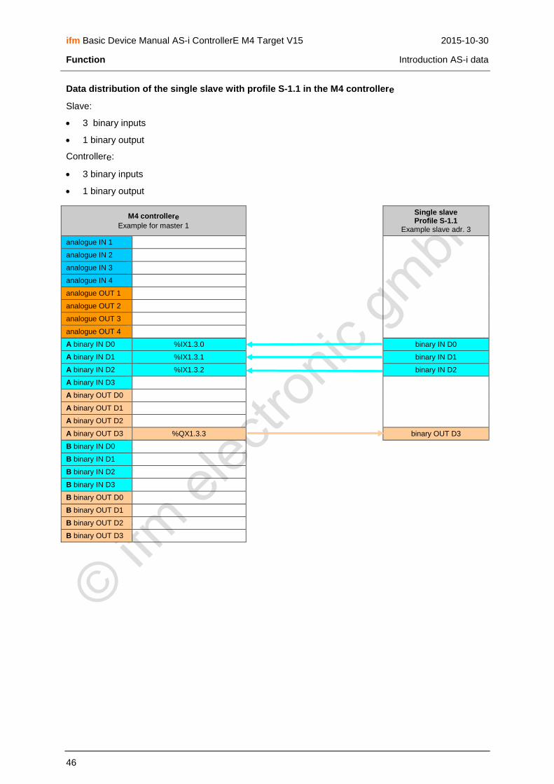
ifm Basic Device Manual AS-i ControllerE M4 Target V15 2015-10-30
Function Introduction AS-i data
46
Data distribution of the single slave with profile S-1.1 in the M4 controllere
Slave:
3 binary inputs
1 binary output
Controllere:
3 binary inputs
1 binary output
M4 controllere
Example for master 1
Single slave Profile S-1.1
Example slave adr. 3
analogue IN 1
analogue IN 2
analogue IN 3
analogue IN 4
analogue OUT 1
analogue OUT 2
analogue OUT 3
analogue OUT 4
A binary IN D0 %IX1.3.0 binary IN D0
A binary IN D1 %IX1.3.1 binary IN D1
A binary IN D2 %IX1.3.2 binary IN D2
A binary IN D3
A binary OUT D0
A binary OUT D1
A binary OUT D2
A binary OUT D3 %QX1.3.3 binary OUT D3
B binary IN D0
B binary IN D1
B binary IN D2
B binary IN D3
B binary OUT D0
B binary OUT D1
B binary OUT D2
B binary OUT D3

ifm Basic Device Manual AS-i ControllerE M4 Target V15 2015-10-30
Function Introduction AS-i data
47
Data distribution of the single slave with profile S-3.1 in the M4 controllere
Slave:
2 binary inputs for 1 dual-signal sensor
2 binary outputs for 1 dual-signal actuator
Controllere:
2 binary inputs + 2 binary outputs
M4 controllere
Example for master 1
Single slave Profile S-3.1
Example slave adr. 3
analogue IN 1
analogue IN 2
analogue IN 3
analogue IN 4
analogue OUT 1
analogue OUT 2
analogue OUT 3
analogue OUT 4
A binary IN D0 %IX1.3.0 binary IN D0
A binary IN D1 %IX1.3.1 binary IN D1
A binary IN D2
A binary IN D3
A binary OUT D0
A binary OUT D1
A binary OUT D2 %QX1.3.2 binary OUT D2
A binary OUT D3 %QX1.3.3 binary OUT D3
B binary IN D0
B binary IN D1
B binary IN D2
B binary IN D3
B binary OUT D0
B binary OUT D1
B binary OUT D2
B binary OUT D3

ifm Basic Device Manual AS-i ControllerE M4 Target V15 2015-10-30
Function Introduction AS-i data
48
Data distribution of the A slave with profile S-3.A in the M4 controllere
Slave:
2 binary inputs
1 binary output
Controllere:
2 binary inputs + 1 binary output
M4 controllere
Example for master 1
A slave profile S-3.A
Example slave adr. 3A
analogue IN 1
analogue IN 2
analogue IN 3
analogue IN 4
analogue OUT 1
analogue OUT 2
analogue OUT 3
analogue OUT 4
A binary IN D0 %IX1.3.0 binary IN D0
A binary IN D1 %IX1.3.1 binary IN D1
A binary IN D2
A binary IN D3
A binary OUT D0
A binary OUT D1
A binary OUT D2 %QX1.3.2 binary OUT D2
A binary OUT D3
B binary IN D0
B binary IN D1
B binary IN D2
B binary IN D3
B binary OUT D0
B binary OUT D1
B binary OUT D2
B binary OUT D3
For slaves with extended addressing mode (ID code = A) the master uses the binary output bit D3 to distinguish between A and B slaves. D3 cannot be used.

ifm Basic Device Manual AS-i ControllerE M4 Target V15 2015-10-30
Function Introduction AS-i data
49
Data distribution of the B slave with profile S-3.A in the M4 controllere
Slave:
2 binary inputs
1 binary output
Controllere:
2 binary inputs + 1 binary output
M4 controllere
Example for master 1
B slave profile S-3.A
Example slave adr. 3B
analogue IN 1
analogue IN 2
analogue IN 3
analogue IN 4
analogue OUT 1
analogue OUT 2
analogue OUT 3
analogue OUT 4
A binary IN D0 binary IN D0
A binary IN D1 binary IN D1
A binary IN D2
A binary IN D3
A binary OUT D0
A binary OUT D1
A binary OUT D2 binary OUT D2
A binary OUT D3
B binary IN D0 %IX11.3.0
B binary IN D1 %IX11.3.1
B binary IN D2
B binary IN D3
B binary OUT D0
B binary OUT D1
B binary OUT D2 %QX11.3.2
B binary OUT D3
For slaves with extended addressing mode (ID code = A) the master uses the binary output bit D3 to distinguish between A and B slaves. D3 cannot be used.

ifm Basic Device Manual AS-i ControllerE M4 Target V15 2015-10-30
Function Introduction AS-i data
50
Data distribution of the single slave with profile S-6.0.x in the M4 controllere (transpar. mode)
The slave module contains 2...4 successive slave addresses with digital data.
Slave:
Number slave addresses
Data length bit stream
Slave profile for ...
1st slave 2nd slave 3rd slave 4th slave
2 8 bits S-6.0.2 S-6.0.5 –– ––
3 12 bits S-6.0.3 S-6.0.6 S-6.0.5 ––
4 16 bits S-6.0.4 S-6.0.7 S-6.0.6 S-6.0.5
Controllere:
1 input channel + 1 output channel (if less than 4 slave addresses only partly used and always filled from left (D15) to right (D0))
Example: first slave address = 3 and data length = 16 bits
M4 controllere Single slave profile S-6.0.x
analogue IN 1 15…12 11…8 7…4 3…0 %IW21.3.0 Slave profile S-6.0.4 (adr.= 3)
analogue IN 2 binary IN D0
analogue IN 3 binary IN D1
analogue IN 4 binary IN D2
analogue OUT 1 15…12 11…8 7…4 3…0 %QW21.3.0 binary IN D3
analogue OUT 2 binary OUT D0
analogue OUT 3 binary OUT D1
analogue OUT 4 binary OUT D2
A binary IN D0 binary OUT D3
A binary IN D1 Slave profile S-6.0.7 (adr.= 4)
A binary IN D2 binary IN D0
A binary IN D3 binary IN D1
A binary OUT D0 binary IN D2
A binary OUT D1 binary IN D3
A binary OUT D2 binary OUT D0
A binary OUT D3 binary OUT D1
B binary IN D0 binary OUT D2
B binary IN D1 binary OUT D3
B binary IN D2 Slave profile S-6.0.6 (adr.= 5)
B binary IN D3 binary IN D0
B binary OUT D0 binary IN D1
B binary OUT D1 binary IN D2
B binary OUT D2 binary IN D3
B binary OUT D3 binary OUT D0
binary OUT D1
binary OUT D2
binary OUT D3
Slave profile S-6.0.5 (adr.= 6)
binary IN D0
binary IN D1
binary IN D2
binary IN D3
binary OUT D0
binary OUT D1
binary OUT D2
binary OUT D3

ifm Basic Device Manual AS-i ControllerE M4 Target V15 2015-10-30
Function Introduction AS-i data
51
Data distribution of the single slave with profile S-6.0.x in the M4 controllere (analogue mode)
The slave modue contains 2...4 successive slave addresses with binary data which together represent an analogue value.
Slave:
Number slave addresses
Data length bit stream
Slave profile for …
1st slave 2nd slave 3rd slave 4th slave
2 8 bits S-6.0.A S-6.0.5 –– ––
3 12 bits S-6.0.B S-6.0.6 S-6.0.5 ––
4 16 bits S-6.0.C S-6.0.7 S-6.0.6 S-6.0.5
Controllere:
1 input channel + 1 output channel (if less than 4 slave addresses only partly used and always filled from left (D15) to right (D0))
Example: first slave address = 3 and data length = 12 bits
M4 controllere Single slave profile S-6.0.x
analogue IN 1 15*…12 11…8 7…4 3…0 %IW21.3.0 Slave profile S-6.0.B (adr.= 3)
analogue IN 2 unused data filled with 0 from right
binary IN D0
analogue IN 3 binary IN D1
analogue IN 4 binary IN D2
analogue OUT 1 15*…12 11…8 7…4 3…0 %QW21.3.0 binary IN D3
analogue OUT 2 binary OUT D0
analogue OUT 3 binary OUT D1
analogue OUT 4 binary OUT D2
A binary IN D0 binary OUT D3
A binary IN D1 Slave profile S-6.0.7 (adr.= 4)
A binary IN D2 binary IN D0
A binary IN D3 binary IN D1
A binary OUT D0 binary IN D2
A binary OUT D1 binary IN D3
A binary OUT D2 binary OUT D0
A binary OUT D3 binary OUT D1
B binary IN D0 binary OUT D2
B binary IN D1 binary OUT D3
B binary IN D2 Slave profile S-6.0.6 (adr.= 5)
B binary IN D3 binary IN D0
B binary OUT D0 binary IN D1
B binary OUT D1 binary IN D2
B binary OUT D2 binary IN D3
B binary OUT D3 binary OUT D0
binary OUT D1
binary OUT D2
binary OUT D3
* Data bit D15 = bit with sign therefore the highest slave number always provides the sign of the analogue value and the 3 most significant bits of the analogue value.

ifm Basic Device Manual AS-i ControllerE M4 Target V15 2015-10-30
Function Introduction AS-i data
52
Data distribution of the single slave with profile S-7.3.4 in the M4 controllere
Slave:
1-channel analogue output
Controllere:
1 output channel
M4 controllere
Example for master 1
Single slave Profile S-7.3.4
Example slave adr. 3
analogue IN 1
analogue IN 2
analogue IN 3
analogue IN 4
analogue OUT 1 %QW21.3.0 analogue OUT 1
analogue OUT 2
analogue OUT 3
analogue OUT 4
A binary IN D0
A binary IN D1
A binary IN D2
A binary IN D3
A binary OUT D0
A binary OUT D1
A binary OUT D2
A binary OUT D3
B binary IN D0
B binary IN D1
B binary IN D2
B binary IN D3
B binary OUT D0
B binary OUT D1
B binary OUT D2
B binary OUT D3

ifm Basic Device Manual AS-i ControllerE M4 Target V15 2015-10-30
Function Introduction AS-i data
53
Data distribution of the single slave with profile S-7.3.5 in the M4 controllere
Slave:
2-channel analogue outputs
Controllere:
2 output channels
M4 controllere
Example for master 1
Single slave Profile S-7.3.5
Example slave adr. 3
analogue IN 1
analogue IN 2
analogue IN 3
analogue IN 4
analogue OUT 1 %QW21.3.0 analogue OUT 1
analogue OUT 2 %QW21.3.1 analogue OUT 2
analogue OUT 3
analogue OUT 4
A binary IN D0
A binary IN D1
A binary IN D2
A binary IN D3
A binary OUT D0
A binary OUT D1
A binary OUT D2
A binary OUT D3
B binary IN D0
B binary IN D1
B binary IN D2
B binary IN D3
B binary OUT D0
B binary OUT D1
B binary OUT D2
B binary OUT D3

ifm Basic Device Manual AS-i ControllerE M4 Target V15 2015-10-30
Function Introduction AS-i data
54
Data distribution of the single slave with profile S-7.3.6 in the M4 controllere
Slave:
4 channels analogue outputs
Controllere:
4 output channels
M4 controllere
Example for master 1
Single slave Profile S-7.3.6
Example slave adr. 3
analogue IN 1
analogue IN 2
analogue IN 3
analogue IN 4
analogue OUT 1 %QW21.3.0 analogue OUT 1
analogue OUT 2 %QW21.3.1 analogue OUT 2
analogue OUT 3 %QW21.3.2 analogue OUT 3
analogue OUT 4 %QW21.3.3 analogue OUT 4
A binary IN D0
A binary IN D1
A binary IN D2
A binary IN D3
A binary OUT D0
A binary OUT D1
A binary OUT D2
A binary OUT D3
B binary IN D0
B binary IN D1
B binary IN D2
B binary IN D3
B binary OUT D0
B binary OUT D1
B binary OUT D2
B binary OUT D3

ifm Basic Device Manual AS-i ControllerE M4 Target V15 2015-10-30
Function Introduction AS-i data
55
Data distribution of the single slave with profile S-7.3.C in the M4 controllere
Slave:
1-channel analogue input
Controllere:
1 input channel
M4 controllere
Example for master 1
Single slave Profile S-7.3.C
Example slave adr. 3
analogue IN 1 %IW21.3.0 analogue IN 1
analogue IN 2
analogue IN 3
analogue IN 4
analogue OUT 1
analogue OUT 2
analogue OUT 3
analogue OUT 4
A binary IN D0
A binary IN D1
A binary IN D2
A binary IN D3
A binary OUT D0
A binary OUT D1
A binary OUT D2
A binary OUT D3
B binary IN D0
B binary IN D1
B binary IN D2
B binary IN D3
B binary OUT D0
B binary OUT D1
B binary OUT D2
B binary OUT D3

ifm Basic Device Manual AS-i ControllerE M4 Target V15 2015-10-30
Function Introduction AS-i data
56
Data distribution of the single slave with profile S-7.3.D in the M4 controllere
Slave:
2-channel analogue inputs
Controllere:
2 input channels
M4 controllere
Example for master 1
Single slave Profile S-7.3.D
Example slave adr. 3
analogue IN 1 %IW21.3.0 analogue IN 1
analogue IN 2 %IW21.3.1 analogue IN 2
analogue IN 3
analogue IN 4
analogue OUT 1
analogue OUT 2
analogue OUT 3
analogue OUT 4
A binary IN D0
A binary IN D1
A binary IN D2
A binary IN D3
A binary OUT D0
A binary OUT D1
A binary OUT D2
A binary OUT D3
B binary IN D0
B binary IN D1
B binary IN D2
B binary IN D3
B binary OUT D0
B binary OUT D1
B binary OUT D2
B binary OUT D3

ifm Basic Device Manual AS-i ControllerE M4 Target V15 2015-10-30
Function Introduction AS-i data
57
Data distribution of the single slave with profile S-7.3.E in the M4 controllere
Slave:
2-channel analogue inputs
Controllere:
2 input channels
M4 controllere
Example for master 1
Single slave Profile S-7.3.E
Example slave adr. 3
analogue IN 1 %IW21.3.0 analogue IN 1
analogue IN 2 %IW21.3.1 analogue IN 2
analogue IN 3 %IW21.3.2 analogue IN 3
analogue IN 4 %IW21.3.3 analogue IN 4
analogue OUT 1
analogue OUT 2
analogue OUT 3
analogue OUT 4
A binary IN D0
A binary IN D1
A binary IN D2
A binary IN D3
A binary OUT D0
A binary OUT D1
A binary OUT D2
A binary OUT D3
B binary IN D0
B binary IN D1
B binary IN D2
B binary IN D3
B binary OUT D0
B binary OUT D1
B binary OUT D2
B binary OUT D3

ifm Basic Device Manual AS-i ControllerE M4 Target V15 2015-10-30
Function Introduction AS-i data
58
Data distribution of the single slave with profile S-7.4.0 in the M4 controllere
Slave: E type field in the ID string of the slave = 3
4 binary inputs + 4 binary outputs
16-bit integer OR bit stream
device string
parameter string
diagnostic string
Controllere:
4 binary inputs + 4 binary outputs
M4 controllere
Example for master 1
Single slave Profile S-7.4.0
Example slave adr. 3
analogue IN 1
analogue IN 2
analogue IN 3
analogue IN 4
analogue OUT 1
analogue OUT 2
analogue OUT 3
analogue OUT 4
A binary IN D0 %IX1.3.0 binary IN D0
A binary IN D1 %IX1.3.1 binary IN D1
A binary IN D2 %IX1.3.2 binary IN D2
A binary IN D3 %IX1.3.3 binary IN D3
A binary OUT D0 %QX1.3.0 binary OUT D0
A binary OUT D1 %QX1.31 binary OUT D1
A binary OUT D2 %QX1.3.2 binary OUT D2
A binary OUT D3 %QX1.3.3 binary OUT D3
B binary IN D0
B binary IN D1
B binary IN D2
B binary IN D3
B binary OUT D0
B binary OUT D1
B binary OUT D2
B binary OUT D3

ifm Basic Device Manual AS-i ControllerE M4 Target V15 2015-10-30
Function Introduction AS-i data
59
Data distribution of the single slave with profile S-7.4.4 in the M4 controllere
Slave: E type field in the ID string of the slave = 1
1-channel analogue output
16-bit integer OR bit stream
device string
parameter string
diagnostic string
Controllere:
1 output channel
M4 controllere
Example for master 1
Single slave Profile S-7.4.4
Example slave adr. 3
analogue IN 1
analogue IN 2
analogue IN 3
analogue IN 4
analogue OUT 1 %QW21.3.0 analogue OUT 1
analogue OUT 2
analogue OUT 3
analogue OUT 4
A binary IN D0
A binary IN D1
A binary IN D2
A binary IN D3
A binary OUT D0
A binary OUT D1
A binary OUT D2
A binary OUT D3
B binary IN D0
B binary IN D1
B binary IN D2
B binary IN D3
B binary OUT D0
B binary OUT D1
B binary OUT D2
B binary OUT D3

ifm Basic Device Manual AS-i ControllerE M4 Target V15 2015-10-30
Function Introduction AS-i data
60
Data distribution of the single slave with profile S-7.4.5 in the M4 controllere
Slave: E type field in the ID string of the slave = 3
2-channel analogue outputs
16-bit integer OR bit stream
device string
parameter string
diagnostic string
Controllere:
2 output channels
M4 controllere
Example for master 1
Single slave Profile S-7.4.5
Example slave adr. 3
analogue IN 1
analogue IN 2
analogue IN 3
analogue IN 4
analogue OUT 1 %QW21.3.0 analogue OUT 1
analogue OUT 2 %QW21.3.1 analogue OUT 2
analogue OUT 3
analogue OUT 4
A binary IN D0
A binary IN D1
A binary IN D2
A binary IN D3
A binary OUT D0
A binary OUT D1
A binary OUT D2
A binary OUT D3
B binary IN D0
B binary IN D1
B binary IN D2
B binary IN D3
B binary OUT D0
B binary OUT D1
B binary OUT D2
B binary OUT D3

ifm Basic Device Manual AS-i ControllerE M4 Target V15 2015-10-30
Function Introduction AS-i data
61
Data distribution of the single slave with profile S-7.4.6 in the M4 controllere
Slave: E type field in the ID string of the slave = 3
4-channel analogue outputs
16-bit integer OR bit stream
device string
parameter string
diagnostic string
Controllere:
4 output channels
M4 controllere
Example for master 1
Single slave Profile S-7.4.6
Example slave adr. 3
analogue IN 1
analogue IN 2
analogue IN 3
analogue IN 4
analogue OUT 1 %QW21.3.0 analogue OUT 1
analogue OUT 2 %QW21.3.1 analogue OUT 2
analogue OUT 3 %QW21.3.2 analogue OUT 3
analogue OUT 4 %QW21.3.3 analogue OUT 4
A binary IN D0
A binary IN D1
A binary IN D2
A binary IN D3
A binary OUT D0
A binary OUT D1
A binary OUT D2
A binary OUT D3
B binary IN D0
B binary IN D1
B binary IN D2
B binary IN D3
B binary OUT D0
B binary OUT D1
B binary OUT D2
B binary OUT D3

ifm Basic Device Manual AS-i ControllerE M4 Target V15 2015-10-30
Function Introduction AS-i data
62
Data distribution of the single slave with profile S-7.4.C in the M4 controllere
Slave: E type field in the ID string of the slave = 3
1-channel analogue input
16-bit integer OR bit stream
device string
parameter string
diagnostic string
Controllere:
1 input channel
M4 controllere
Example for master 1
Single slave Profile S-7.4.C
Example slave adr. 3
analogue IN 1 %IW21.3.0 analogue IN 1
analogue IN 2
analogue IN 3
analogue IN 4
analogue OUT 1
analogue OUT 2
analogue OUT 3
analogue OUT 4
A binary IN D0
A binary IN D1
A binary IN D2
A binary IN D3
A binary OUT D0
A binary OUT D1
A binary OUT D2
A binary OUT D3
B binary IN D0
B binary IN D1
B binary IN D2
B binary IN D3
B binary OUT D0
B binary OUT D1
B binary OUT D2
B binary OUT D3

ifm Basic Device Manual AS-i ControllerE M4 Target V15 2015-10-30
Function Introduction AS-i data
63
Data distribution of the single slave with profile S-7.4.D in the M4 controllere
Slave: E type field in the ID string of the slave = 3
2-channel analogue inputs
16-bit integer OR bit stream
device string
parameter string
diagnostic string
Controllere:
2 input channels
M4 controllere
Example for master 1
Single slave Profile S-7.4.D
Example slave adr. 3
analogue IN 1 %IW21.3.0 analogue IN 1
analogue IN 2 %IW21.3.1 analogue IN 2
analogue IN 3
analogue IN 4
analogue OUT 1
analogue OUT 2
analogue OUT 3
analogue OUT 4
A binary IN D0
A binary IN D1
A binary IN D2
A binary IN D3
A binary OUT D0
A binary OUT D1
A binary OUT D2
A binary OUT D3
B binary IN D0
B binary IN D1
B binary IN D2
B binary IN D3
B binary OUT D0
B binary OUT D1
B binary OUT D2
B binary OUT D3

ifm Basic Device Manual AS-i ControllerE M4 Target V15 2015-10-30
Function Introduction AS-i data
64
Data distribution of the single slave with profile S-7.4.E in the M4 controllere
Slave: E type field in the ID string of the slave = 3
4-channel analogue inputs
16-bit integer OR bit stream
device string
parameter string
diagnostic string
Controllere:
4 input channels
M4 controllere
Example for master 1
Single slave Profile S-7.4.E
Example slave adr. 3
analogue IN 1 %IW21.3.0 analogue IN 1
analogue IN 2 %IW21.3.1 analogue IN 2
analogue IN 3 %IW21.3.2 analogue IN 3
analogue IN 4 %IW21.3.3 analogue IN 4
analogue OUT 1
analogue OUT 2
analogue OUT 3
analogue OUT 4
A binary IN D0
A binary IN D1
A binary IN D2
A binary IN D3
A binary OUT D0
A binary OUT D1
A binary OUT D2
A binary OUT D3
B binary IN D0
B binary IN D1
B binary IN D2
B binary IN D3
B binary OUT D0
B binary OUT D1
B binary OUT D2
B binary OUT D3

ifm Basic Device Manual AS-i ControllerE M4 Target V15 2015-10-30
Function Introduction AS-i data
65
Data distribution of the single slave with profile S-7.5.5 in the M4 controllere
Slave:
0…4-channel analogue inputs OR < 64-bit binary inputs
0…4-channel analogue outputs OR < 64-bit binary outputs
2 binary inputs + 2 binary outputs
16-bit integer OR bit stream
device string
parameter string
diagnostic string
Controllere:
0…4 input channels
0…4 output channels
2 binary inputs + 2 binary outputs
Figure: diagram for analogue signals
M4 controllere
Example for master 1
Single slave Profile S-7.5.5
Example slave adr. 3
analogue IN 1 %IW21.3.0 analogue IN 1
analogue IN 2 %IW21.3.1 analogue IN 2
analogue IN 3 %IW21.3.2 analogue IN 3
analogue IN 4 %IW21.3.3 analogue IN 4
analogue OUT 1 %QW21.3.0 analogue OUT 1
analogue OUT 2 %QW21.3.1 analogue OUT 2
analogue OUT 3 %QW21.3.2 analogue OUT 3
analogue OUT 4 %QW21.3.3 analogue OUT 4
A binary IN D0 %IX1.0 binary IN D0
A binary IN D1 %IX1.1 binary IN D1
A binary IN D2
A binary IN D3
A binary OUT D0
A binary OUT D1
A binary OUT D2 %QX1.2 binary OUT D2
A binary OUT D3 %QX1.3 binary OUT D3
B binary IN D0
B binary IN D1
B binary IN D2
B binary IN D3
B binary OUT D0
B binary OUT D1
B binary OUT D2
B binary OUT D3

ifm Basic Device Manual AS-i ControllerE M4 Target V15 2015-10-30
Function Introduction AS-i data
66
Figure: diagram for binary signals
M4 controllere
Example for master 1
Single slave Profile S-7.5.5
Example slave adr. 3
analogue IN 1 %IW21.3.0 < 16-bit binary IN
analogue IN 2 %IW21.3.1 < 16-bit binary IN
analogue IN 3 %IW21.3.2 < 16-bit binary IN
analogue IN 4 %IW21.3.3 < 16-bit binary IN
analogue OUT 1 %QW21.3.0 < 16-bit binary OUT
analogue OUT 2 %QW21.3.1 < 16-bit binary OUT
analogue OUT 3 %QW21.3.2 < 16-bit binary OUT
analogue OUT 4 %QW21.3.3 < 16-bit binary OUT
A binary IN D0 %IX1.0 binary IN D0
A binary IN D1 %IX1.1 binary IN D1
A binary IN D2
A binary IN D3
A binary OUT D0
A binary OUT D1
A binary OUT D2 %QX1.2 binary OUT D2
A binary OUT D3 %QX1.3 binary OUT D3
B binary IN D0
B binary IN D1
B binary IN D2
B binary IN D3
B binary OUT D0
B binary OUT D1
B binary OUT D2
B binary OUT D3

ifm Basic Device Manual AS-i ControllerE M4 Target V15 2015-10-30
Function Introduction AS-i data
67
Data distribution of the A slave with profile S-7.A.5 in the M4 controllere
Slave:
0…2-channel analogue inputs OR < 32-bit binary inputs
0…2-channel analogue outputs OR < 32-bit binary outputs
2 binary inputs + 1 binary output
16-bit integer OR bit stream
device string
parameter string
diagnostic string
Controllere:
0…2 input channels
0…2 output channels
2 binary inputs + 1 binary output
Figure: diagram for analogue signals:
M4 controllere
Example for master 1
A slave Profile S-7.A.5
Example slave adr. 3A
analogue IN 1 %IW21.3.0 analogue IN 1
analogue IN 2 %IW21.3.1 analogue IN 2
analogue IN 3
analogue IN 4
analogue OUT 1 %QW21.3.0 analogue OUT 1
analogue OUT 2 %QW21.3.1 analogue OUT 2
analogue OUT 3
analogue OUT 4
A binary IN D0 %IX1.0 binary IN D0
A binary IN D1 %IX1.1 binary IN D1
A binary IN D2
A binary IN D3
A binary OUT D0
A binary OUT D1
A binary OUT D2 %QX1.2 binary OUT D2
A binary OUT D3
B binary IN D0
B binary IN D1
B binary IN D2
B binary IN D3
B binary OUT D0
B binary OUT D1
B binary OUT D2
B binary OUT D3

ifm Basic Device Manual AS-i ControllerE M4 Target V15 2015-10-30
Function Introduction AS-i data
68
Figure: diagram for binary signals:
M4 controllere
Example for master 1
A slave Profile S-7.A.5
Example slave adr. 3A
analogue IN 1 %IW21.3.0 < 16-bit binary IN
analogue IN 2 %IW21.3.1 < 16-bit binary IN
analogue IN 3
analogue IN 4
analogue OUT 1 %QW21.3.0 < 16-bit binary OUT
analogue OUT 2 %QW21.3.1 < 16-bit binary OUT
analogue OUT 3
analogue OUT 4
A binary IN D0 %IX1.0 binary IN D0
A binary IN D1 %IX1.1 binary IN D1
A binary IN D2
A binary IN D3
A binary OUT D0
A binary OUT D1
A binary OUT D2 %QX1.2 binary OUT D2
A binary OUT D3
B binary IN D0
B binary IN D1
B binary IN D2
B binary IN D3
B binary OUT D0
B binary OUT D1
B binary OUT D2
B binary OUT D3

ifm Basic Device Manual AS-i ControllerE M4 Target V15 2015-10-30
Function Introduction AS-i data
69
Data distribution of the B slave with profile S-7.A.5 in the M4 controllere
Slave:
0…2-channel analogue inputs OR < 32-bit binary inputs
0…2-channel analogue outputs OR < 32-bit binary outputs
2 binary inputs + 1 binary output
16-bit integer OR bit stream
device string
parameter string
diagnostic string
Controllere:
0…2 input channels
0…2 output channels
2 binary inputs + 1 binary output
Figure: diagram for analogue signals:
M4 controllere
Example for master 1
B slave Profile S-7.A.5
Example slave adr. 3B
analogue IN 1 analogue IN 1
analogue IN 2 analogue IN 2
analogue IN 3 %IW21.3.2
analogue IN 4 %IW21.3.3
analogue OUT 1 analogue OUT 1
analogue OUT 2 analogue OUT 2
analogue OUT 3 %QW21.3.2
analogue OUT 4 %QW21.3.3
A binary IN D0 binary IN D0
A binary IN D1 binary IN D1
A binary IN D2
A binary IN D3
A binary OUT D0
A binary OUT D1
A binary OUT D2 binary OUT D2
A binary OUT D3
B binary IN D0 %IX11.3.0
B binary IN D1 %IX11.3.1
B binary IN D2
B binary IN D3
B binary OUT D0
B binary OUT D1
B binary OUT D2 %QX11.3.2
B binary OUT D3

ifm Basic Device Manual AS-i ControllerE M4 Target V15 2015-10-30
Function Introduction AS-i data
70
Figure: diagram for binary signals:
M4 controllere
Example for master 1
B slave Profile S-7.A.5
Example slave adr. 3B
analogue IN 1 < 16-bit binary IN
analogue IN 2 < 16-bit binary IN
analogue IN 3 %IW21.3.2
analogue IN 4 %IW21.3.3
analogue OUT 1 < 16-bit binary OUT
analogue OUT 2 < 16-bit binary OUT
analogue OUT 3 %QW21.3.2
analogue OUT 4 %QW21.3.3
A binary IN D0 binary IN D0
A binary IN D1 binary IN D1
A binary IN D2
A binary IN D3
A binary OUT D0
A binary OUT D1
A binary OUT D2 binary OUT D2
A binary OUT D3
B binary IN D0 %IX11.3.0
B binary IN D1 %IX11.3.1
B binary IN D2
B binary IN D3
B binary OUT D0
B binary OUT D1
B binary OUT D2 %QX11.3.2
B binary OUT D3

ifm Basic Device Manual AS-i ControllerE M4 Target V15 2015-10-30
Function Introduction AS-i data
71
Data distribution of the A slave with profile S-7.A.7 in the M4 controllere
Slave:
4 binary inputs + 4 binary outputs
16-bit integer OR bit stream
Controllere:
4 binary inputs + 4 binary outputs
M4 controllere
Example for master 1
A slave Profile S-7.A.7
Example slave adr. 3A
analogue IN 1
analogue IN 2
analogue IN 3
analogue IN 4
analogue OUT 1
analogue OUT 2
analogue OUT 3
analogue OUT 4
A binary IN D0 %IX1.3.0 binary IN D0
A binary IN D1 %IX1.3.1 binary IN D1
A binary IN D2 %IX1.3.2 binary IN D2
A binary IN D3 %IX1.3.3 binary IN D3
A binary OUT D0 %QX1.3.0 binary OUT D0
A binary OUT D1 %QX1.3.1 binary OUT D1
A binary OUT D2 %QX1.3.2 binary OUT D2
A binary OUT D3 %QX1.3.3 binary OUT D3
B binary IN D0
B binary IN D1
B binary IN D2
B binary IN D3
B binary OUT D0
B binary OUT D1
B binary OUT D2
B binary OUT D3

ifm Basic Device Manual AS-i ControllerE M4 Target V15 2015-10-30
Function Introduction AS-i data
72
Data distribution of the B slave with profile S-7.A.7 in the M4 controllere
Slave:
4 binary inputs + 4 binary outputs
16-bit integer OR bit stream
Controllere:
4 binary inputs + 4 binary outputs
M4 controllere
Example for master 1
B slave Profile S-7.A.7
Example slave adr. 3B
analogue IN 1
analogue IN 2
analogue IN 3
analogue IN 4
analogue OUT 1
analogue OUT 2
analogue OUT 3
analogue OUT 4
A binary IN D0 binary IN D0
A binary IN D1 binary IN D1
A binary IN D2 binary IN D2
A binary IN D3 binary IN D3
A binary OUT D0 binary OUT D0
A binary OUT D1 binary OUT D1
A binary OUT D2 binary OUT D2
A binary OUT D3 binary OUT D3
B binary IN D0 %IX11.3.0
B binary IN D1 %IX11.3.1
B binary IN D2 %IX11.3.2
B binary IN D3 %IX11.3.3
B binary OUT D0 %QX11.3.0
B binary OUT D1 %QX11.3.1
B binary OUT D2 %QX11.3.2
B binary OUT D3 %QX11.3.3

ifm Basic Device Manual AS-i ControllerE M4 Target V15 2015-10-30
Function Introduction AS-i data
73
Data distribution of the A slave with profile S-7.A.8 in the M4 controllere
Slave:
1-channel analogue input OR < 16-bit binary inputs
1 binary output
14/16-bit integer OR 8/12/16-bit bit stream
Controllere:
1 input channel
1 binary output
Figure: diagram for analogue signals:
M4 controllere
Example for master 1
A slave Profile S-7.A.8
Example slave adr. 3A
analogue IN 1 %IW21.3.0 analogue IN 1
analogue IN 2
analogue IN 3
analogue IN 4
analogue OUT 1
analogue OUT 2
analogue OUT 3
analogue OUT 4
A binary IN D0
A binary IN D1
A binary IN D2
A binary IN D3
A binary OUT D0
A binary OUT D1
A binary OUT D2 %QX1.3.2 binary OUT D2
A binary OUT D3
B binary IN D0
B binary IN D1
B binary IN D2
B binary IN D3
B binary OUT D0
B binary OUT D1
B binary OUT D2
B binary OUT D3

ifm Basic Device Manual AS-i ControllerE M4 Target V15 2015-10-30
Function Introduction AS-i data
74
Figure: diagram for binary signals:
M4 controllere
Example for master 1
A slave Profile S-7.A.8
Example slave adr. 3A
analogue IN 1 %IW21.3.0 < 16-bit binary IN
analogue IN 2
analogue IN 3
analogue IN 4
analogue OUT 1
analogue OUT 2
analogue OUT 3
analogue OUT 4
A binary IN D0
A binary IN D1
A binary IN D2
A binary IN D3
A binary OUT D0
A binary OUT D1
A binary OUT D2 %QX1.3.2 binary OUT D2
A binary OUT D3
B binary IN D0
B binary IN D1
B binary IN D2
B binary IN D3
B binary OUT D0
B binary OUT D1
B binary OUT D2
B binary OUT D3

ifm Basic Device Manual AS-i ControllerE M4 Target V15 2015-10-30
Function Introduction AS-i data
75
Data distribution of the B slave with profile S-7.A.8 in the M4 controllere
Slave:
1-channel analogue input OR < 16-bit binary inputs
1 binary output
14/16-bit integer OR 8/12/16-bit bit stream
Controllere:
1 input channel
1 binary output
Figure: diagram for analogue signals:
M4 controllere
Example for master 1
B slave Profile S-7.A.8
Example slave adr. 3B
analogue IN 1 analogue IN 1
analogue IN 2
analogue IN 3 %IW21.3.2
analogue IN 4
analogue OUT 1
analogue OUT 2
analogue OUT 3
analogue OUT 4
A binary IN D0
A binary IN D1
A binary IN D2
A binary IN D3
A binary OUT D0
A binary OUT D1
A binary OUT D2 binary OUT D2
A binary OUT D3
B binary IN D0
B binary IN D1
B binary IN D2
B binary IN D3
B binary OUT D0
B binary OUT D1
B binary OUT D2 %QX11.3.2
B binary OUT D3

ifm Basic Device Manual AS-i ControllerE M4 Target V15 2015-10-30
Function Introduction AS-i data
76
Figure: diagram for binary signals:
M4 controllere
Example for master 1
B slave Profile S-7.A.8
Example slave adr. 3B
analogue IN 1 < 16-bit binary IN
analogue IN 2
analogue IN 3 %IW21.3.2
analogue IN 4
analogue OUT 1
analogue OUT 2
analogue OUT 3
analogue OUT 4
A binary IN D0
A binary IN D1
A binary IN D2
A binary IN D3
A binary OUT D0
A binary OUT D1
A binary OUT D2 binary OUT D2
A binary OUT D3
B binary IN D0
B binary IN D1
B binary IN D2
B binary IN D3
B binary OUT D0
B binary OUT D1
B binary OUT D2 %QX11.3.2
B binary OUT D3

ifm Basic Device Manual AS-i ControllerE M4 Target V15 2015-10-30
Function Introduction AS-i data
77
Data distribution of the A slave with profile S-7.A.9 in the M4 controllere
Slave:
2-channel analogue inputs OR < 32-bit binary inputs
12/14-bit integer
Controllere:
2 input channels
Figure: diagram for analogue signals:
M4 controllere
Example for master 1
A slave Profile S-7.A.9
Example slave adr. 3A
analogue IN 1 %IW21.3.0 analogue IN 1
analogue IN 2 %IW21.3.1 analogue IN 2
analogue IN 3
analogue IN 4
analogue OUT 1
analogue OUT 2
analogue OUT 3
analogue OUT 4
A binary IN D0
A binary IN D1
A binary IN D2
A binary IN D3
A binary OUT D0
A binary OUT D1
A binary OUT D2
A binary OUT D3
B binary IN D0
B binary IN D1
B binary IN D2
B binary IN D3
B binary OUT D0
B binary OUT D1
B binary OUT D2
B binary OUT D3

ifm Basic Device Manual AS-i ControllerE M4 Target V15 2015-10-30
Function Introduction AS-i data
78
Figure: diagram for binary signals:
M4 controllere
Example for master 1
A slave Profile S-7.A.9
Example slave adr. 3A
analogue IN 1 %IW21.3.0 < 16-bit binary IN
analogue IN 2 %IW21.3.1 < 16-bit binary IN
analogue IN 3
analogue IN 4
analogue OUT 1
analogue OUT 2
analogue OUT 3
analogue OUT 4
A binary IN D0
A binary IN D1
A binary IN D2
A binary IN D3
A binary OUT D0
A binary OUT D1
A binary OUT D2
A binary OUT D3
B binary IN D0
B binary IN D1
B binary IN D2
B binary IN D3
B binary OUT D0
B binary OUT D1
B binary OUT D2
B binary OUT D3
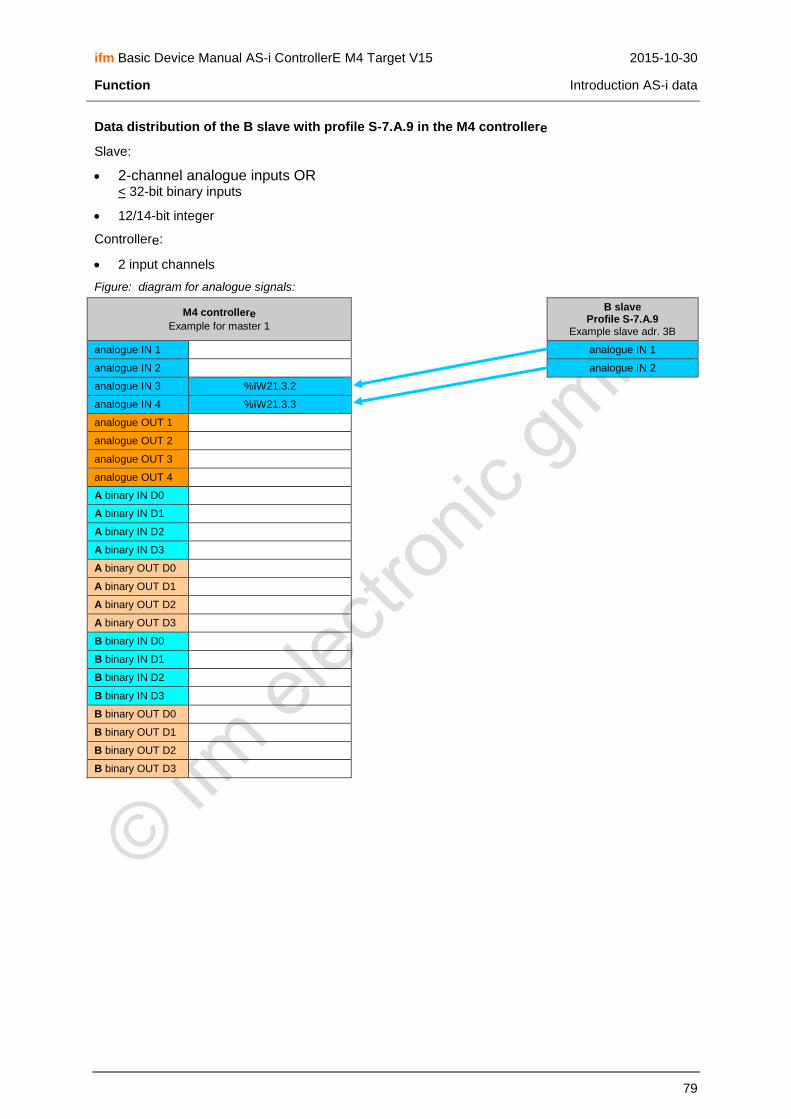
ifm Basic Device Manual AS-i ControllerE M4 Target V15 2015-10-30
Function Introduction AS-i data
79
Data distribution of the B slave with profile S-7.A.9 in the M4 controllere
Slave:
2-channel analogue inputs OR < 32-bit binary inputs
12/14-bit integer
Controllere:
2 input channels
Figure: diagram for analogue signals:
M4 controllere
Example for master 1
B slave Profile S-7.A.9
Example slave adr. 3B
analogue IN 1 analogue IN 1
analogue IN 2 analogue IN 2
analogue IN 3 %IW21.3.2
analogue IN 4 %IW21.3.3
analogue OUT 1
analogue OUT 2
analogue OUT 3
analogue OUT 4
A binary IN D0
A binary IN D1
A binary IN D2
A binary IN D3
A binary OUT D0
A binary OUT D1
A binary OUT D2
A binary OUT D3
B binary IN D0
B binary IN D1
B binary IN D2
B binary IN D3
B binary OUT D0
B binary OUT D1
B binary OUT D2
B binary OUT D3

ifm Basic Device Manual AS-i ControllerE M4 Target V15 2015-10-30
Function Introduction AS-i data
80
Figure: diagram for binary signals:
M4 controllere
Example for master 1
B slave Profile S-7.A.9
Example slave adr. 3B
analogue IN 1 < 16-bit binary IN
analogue IN 2 < 16-bit binary IN
analogue IN 3 %IW21.3.2
analogue IN 4 %IW21.3.3
analogue OUT 1
analogue OUT 2
analogue OUT 3
analogue OUT 4
A binary IN D0
A binary IN D1
A binary IN D2
A binary IN D3
A binary OUT D0
A binary OUT D1
A binary OUT D2
A binary OUT D3
B binary IN D0
B binary IN D1
B binary IN D2
B binary IN D3
B binary OUT D0
B binary OUT D1
B binary OUT D2
B binary OUT D3

ifm Basic Device Manual AS-i ControllerE M4 Target V15 2015-10-30
Function Introduction AS-i data
81
Data distribution of the A slave with profile S-7.A.A in the M4 controllere
Slave:
8 binary inputs + 8 binary outputs
Controllere:
1 input channel
1 output channel
M4 controllere
Example for master 1
A slave Profile S-7.A.A
Example slave adr. 3A
analogue IN 1 –– 7…0 %IW21.3.0 binary IN D0
analogue IN 2 binary IN D1
analogue IN 3 binary IN D2
analogue IN 4 binary IN D3
analogue OUT 1 –– 7…0 %QW21.3.0 binary IN D4
analogue OUT 2 binary IN D5
analogue OUT 3 binary IN D6
analogue OUT 4 binary IN D7
A binary IN D0 binary OUT D0
A binary IN D1 binary OUT D1
A binary IN D2 binary OUT D2
A binary IN D3 binary OUT D3
A binary OUT D0 binary OUT D4
A binary OUT D1 binary OUT D5
A binary OUT D2 binary OUT D6
A binary OUT D3 binary OUT D7
B binary IN D0
B binary IN D1
B binary IN D2
B binary IN D3
B binary OUT D0
B binary OUT D1
B binary OUT D2
B binary OUT D3

ifm Basic Device Manual AS-i ControllerE M4 Target V15 2015-10-30
Function Introduction AS-i data
82
Data distribution of the B slave with profile S-7.A.A in the M4 controllere
Slave:
8 binary inputs + 8 binary outputs
Controllere:
1 input channel
1 output channel
M4 controllere
Example for master 1
B slave Profile S-7.A.A
Example slave adr. 3B
analogue IN 1 binary IN D0
analogue IN 2 binary IN D1
analogue IN 3 –– 7…0 %IW21.3.2 binary IN D2
analogue IN 4 binary IN D3
analogue OUT 1 binary IN D4
analogue OUT 2 binary IN D5
analogue OUT 3 –– 7…0 %QW21.3.2 binary IN D6
analogue OUT 4 binary IN D7
A binary IN D0 binary OUT D0
A binary IN D1 binary OUT D1
A binary IN D2 binary OUT D2
A binary IN D3 binary OUT D3
A binary OUT D0 binary OUT D4
A binary OUT D1 binary OUT D5
A binary OUT D2 binary OUT D6
A binary OUT D3 binary OUT D7
B binary IN D0
B binary IN D1
B binary IN D2
B binary IN D3
B binary OUT D0
B binary OUT D1
B binary OUT D2
B binary OUT D3

ifm Basic Device Manual AS-i ControllerE M4 Target V15 2015-10-30
Function Introduction AS-i data
83
Data distribution of the A slave with profile S-B.A.5 in the M4 controllere
Slave:
0…2-channel analogue inputs OR < 32-bit binary inputs
0…2-channel analogue outputs OR < 32-bit binary outputs
16-bit integer OR bit stream
device string
parameter string
diagnostic string
Controllere:
2 input channels
2 output channels
Figure: diagram for analogue signals:
M4 controllere
Example for master 1
A slave Profile S-B.A.5
Example slave adr. 3A
analogue IN 1 %IW21.3.0 analogue IN 1
analogue IN 2 %IW21.3.1 analogue IN 2
analogue IN 3
analogue IN 4
analogue OUT 1 %QW21.3.0 analogue OUT 1
analogue OUT 2 %QW21.3.1 analogue OUT 2
analogue OUT 3
analogue OUT 4
A binary IN D0
A binary IN D1
A binary IN D2
A binary IN D3
A binary OUT D0
A binary OUT D1
A binary OUT D2
A binary OUT D3
B binary IN D0
B binary IN D1
B binary IN D2
B binary IN D3
B binary OUT D0
B binary OUT D1
B binary OUT D2
B binary OUT D3

ifm Basic Device Manual AS-i ControllerE M4 Target V15 2015-10-30
Function Introduction AS-i data
84
Figure: diagram for binary signals:
M4 controllere
Example for master 1
A slave Profile S-B.A.5
Example slave adr. 3A
analogue IN 1 %IW21.3.0 < 16-bit binary IN
analogue IN 2 %IW21.3.1 < 16-bit binary IN
analogue IN 3
analogue IN 4
analogue OUT 1 %QW21.3.0 < 16-bit binary OUT
analogue OUT 2 %QW21.3.1 < 16-bit binary OUT
analogue OUT 3
analogue OUT 4
A binary IN D0
A binary IN D1
A binary IN D2
A binary IN D3
A binary OUT D0
A binary OUT D1
A binary OUT D2
A binary OUT D3
B binary IN D0
B binary IN D1
B binary IN D2
B binary IN D3
B binary OUT D0
B binary OUT D1
B binary OUT D2
B binary OUT D3

ifm Basic Device Manual AS-i ControllerE M4 Target V15 2015-10-30
Function Introduction AS-i data
85
Data distribution of the B slave with profile S-B.A.5 in the M4 controllere
Slave:
0…2-channel analogue inputs OR < 32-bit binary inputs
0…2-channel analogue outputs OR < 32-bit binary outputs
16-bit integer OR bit stream
device string
parameter string
diagnostic string
Controllere:
2 input channels
2 output channels
Figure: diagram for analogue signals:
M4 controllere
Example for master 1
B slave Profile S-B.A.5
Example slave adr. 3B
analogue IN 1 analogue IN 1
analogue IN 2 analogue IN 2
analogue IN 3 %IW21.3.2
analogue IN 4 %IW21.3.3
analogue OUT 1 analogue OUT 1
analogue OUT 2 analogue OUT 2
analogue OUT 3 %QW21.3.2
analogue OUT 4 %QW21.3.3
A binary IN D0
A binary IN D1
A binary IN D2
A binary IN D3
A binary OUT D0
A binary OUT D1
A binary OUT D2
A binary OUT D3
B binary IN D0
B binary IN D1
B binary IN D2
B binary IN D3
B binary OUT D0
B binary OUT D1
B binary OUT D2
B binary OUT D3

ifm Basic Device Manual AS-i ControllerE M4 Target V15 2015-10-30
Function Introduction AS-i data
86
Figure: diagram for binary signals:
M4 controllere
Example for master 1
B slave Profile S-B.A.5
Example slave adr. 3B
analogue IN 1 < 16-bit binary IN
analogue IN 2 < 16-bit binary IN
analogue IN 3 %IW21.3.2
analogue IN 4 %IW21.3.3
analogue OUT 1 < 16-bit binary OUT
analogue OUT 2 < 16-bit binary OUT
analogue OUT 3 %QW21.3.2
analogue OUT 4 %QW21.3.3
A binary IN D0
A binary IN D1
A binary IN D2
A binary IN D3
A binary OUT D0
A binary OUT D1
A binary OUT D2
A binary OUT D3
B binary IN D0
B binary IN D1
B binary IN D2
B binary IN D3
B binary OUT D0
B binary OUT D1
B binary OUT D2
B binary OUT D3

ifm Basic Device Manual AS-i ControllerE M4 Target V15 2015-10-30
Installation
87
6 Installation
6.1
For installation of the controllere a 35 mm rail to DIN EN 50022 must be used. The device mounted on
the DIN rail can be easily removed from the rail without any tools.
The housing shape was selected to match the current 24 V and AS-i power supplies from ifm electronic. Therefore the controllere having the same height of only 107 mm can be installed in most
control cabinets with a height of 120 mm.
NOTICE
Risk of overheating by incorrect installation! The controllere can overheat and be destroyed.
► Install the controllere only vertically in the control cabinet. This serves for an optimum heat
dissipation from the device.
► When mounting, leave a gap of at least 30 mm above and below the device. Air circulation through the vents must not be hampered.
If the specified distances are adhered to, the device can be operated in a temperature range of 0 °C to
+60 C.
NOTICE
Electromagnetic interference caused by a frequency converter! Frequency converters emit strong electromagnetic interference. This can interfere with the function of the AS-i controllere.
► Install the controllere outside the area of possible electromagnetic interference by neighbouring
frequency converters.
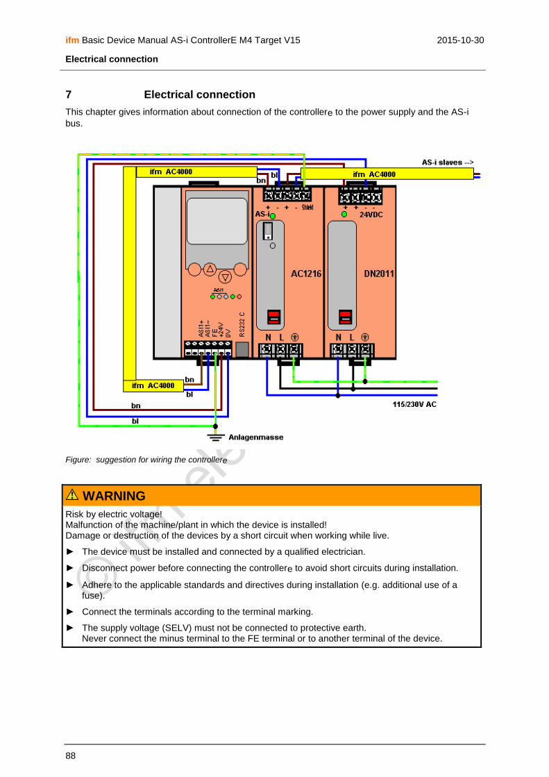
ifm Basic Device Manual AS-i ControllerE M4 Target V15 2015-10-30
Electrical connection
88
7 Electrical connection
This chapter gives information about connection of the controllere to the power supply and the AS-i
bus.
Figure: suggestion for wiring the controllere
WARNING
Risk by electric voltage! Malfunction of the machine/plant in which the device is installed! Damage or destruction of the devices by a short circuit when working while live.
► The device must be installed and connected by a qualified electrician.
► Disconnect power before connecting the controllere to avoid short circuits during installation.
► Adhere to the applicable standards and directives during installation (e.g. additional use of a fuse).
► Connect the terminals according to the terminal marking.
► The supply voltage (SELV) must not be connected to protective earth. Never connect the minus terminal to the FE terminal or to another terminal of the device.

ifm Basic Device Manual AS-i ControllerE M4 Target V15 2015-10-30
Electrical connection Terminals on the controllere
89
7.1 Terminals on the controllere
Connection Description
+24V / 0V Supply voltage 24 V DC (20...30 V PELV), e.g. from the power supply D2011 of ifm electronic
This supply must not be grounded!
Power consumption: up to 500 mA depending on the device version
FE Functional earth of the device
ASI1+ Bus cable AS-i master 1, positive pole (brown)
ASI1- Bus cable AS-i master 1, negative pole (blue)
ASI2+ Bus cable AS-i master 2 (option), positive pole (brown)
ASI2- Bus cable AS-i master 2 (option), negative pole (blue)
RS-232C Serial programming interface
Further terminals for fieldbus and / or Ethernet programming interface are optional and described in separate manuals
The device is correctly connected to the functioning power supplies if the LED [24 V PWR] is lit after power on of the controllere.

ifm Basic Device Manual AS-i ControllerE M4 Target V15 2015-10-30
Electrical connection The AS-i power supply
90
7.2 The AS-i power supply
To operate an AS-i system a special AS-i power supply is required, e.g. AC1216 from ifm electronic. The AS-i power supply supplies the connected slaves with energy via the yellow AS-i cable and at the same time implements data decoupling from the voltage regulator of the power supply. Standard switched-mode power supplies do not feature data decoupling and are therefore not suited for use as AS-i current supply.
In the ifm AS-i power supplies the two terminals AS-i+ and AS-i- are designed redundantly, so that
they can additionally be connected to the terminals ASI 1+ and ASI 1- of the controllere without
additional terminals. The same applies to ASI 2+ and ASI 2- for the second AS-i master circuit.
For the operation of the optional second AS-i master a second AS-i power supply is required, because the two master circuits must be electrically separated. In addition, the AS-i power supply supplies the analogue input part of the controllere.
NOTICE
Overcurrent in case of short circuit! Risk of damage to devices. In case of short circuits, the AS-i power supply provides the maximum current.
► Disconnect the power supply before connecting the controllere.
NOTICE
Interference or corruption of the AS-i signals possible. When the AS-i network is grounded the signals AS-i+ and AS-i- are no longer symmetrical to the ground potential of the machine/plant.
Do NOT ground the AS-i network.
► Connect the "Shield" terminal on the AS-i power supply to the machine ground (GND potential) so that it is well conductive.

ifm Basic Device Manual AS-i ControllerE M4 Target V15 2015-10-30
Electrical connection Wiring and set-up of the slaves
91
7.3 Wiring and set-up of the slaves
In general, the AS-i devices are short-circuit proof and reverse-polarity protected. Control cabinet modules, however, should be wired while disconnected.
7.3.1 Connecting slaves
► Switch off the controllere and its supply.
NOTICE
Malfunction of the machine/plant in which the unit is installed! Damage or destruction of the devices by a short circuit when working while live.
► The device must be installed and connected by a qualified electrician.
► Disconnect power before connecting the device to avoid short circuits during installation.
► Only install the controllere and the slaves while disconnected!
AS-i field modules can be installed without risk while live.
SmartLine modules:
► Connect (control cabinet) modules.
► Remove the Combicon connector with AS-i connection to enable automatic addressing of the slaves in rising order.
AS-i field modules:
AS-i field modules usually consist of a lower part for the connection of the yellow (and black) flat cable and an upper part with the electronics.
► Insert the cable in the lower parts, but do not yet screw/clamp the upper parts on the lower parts to enable automatic addressing of the slaves in rising order.
7.3.2 Switching on the controllere again
After power-on, the two power supplies supply the controllere, the AS-i master and the AS-i bus with
voltage. The green LED [PWR/COM] flashes because no valid slave has been detected yet.
In the next step the slaves must be addressed: → page 126, chapter Configuration

ifm Basic Device Manual AS-i ControllerE M4 Target V15 2015-10-30
Operating and display elements Diagnostic LEDs
92
8 Operating and display elements
In this chapter you will become familiar with the elements on the controllere used:
to operate the device
to obtain information about the device and its configuration
to set parameters for the device and the AS-i slaves.
8.1 Diagnostic LEDs
The three diagnostic LEDs on the controllere inform about the status of the AS-i masters and the
connected systems:
Figure: Diagnostic LEDs
About the figure "diagnostic LEDs":
The LEDs [ASI2] including their labelling are an option for the second AS-i master
The LED [ETH NET] including its labelling is an option for the Ethernet programming interface
Two designations for one LED, separated by a slash "/", signify:
The first designation describes the status in case of a permanently lit LED (mostly normal operation) and
the second designation describes the status in case of a flashing LED (mostly in case of a fault).

ifm Basic Device Manual AS-i ControllerE M4 Target V15 2015-10-30
Operating and display elements Diagnostic LEDs
93
Diagnostic LEDs LED colour
LED out LED lit LED flashes
ASI1 [PWR/COM]
AS-i bus 1: Power Communication
Green No supply for AS-i bus 1
AS-i supply available; at least 1 slave detected on the bus
AS-i supply available; no slave correctly detected on the bus
ASI1 [PROJ]
AS-i bus 1: Projection
Yellow Operating mode active Configuration mode active; configuration monitoring deactivated
Configuration mode active; changeover to protected mode not possible because a slave with the address 0 is connected
ASI1 [CONF/PF]
AS-i bus 1: Configuration Periphery Failure
Red Configuration and periphery ok
Projected and current configuration do not match
Periphery fault detected on at least one connected slave
ASI2 [PWR/COM]
AS-i bus 2: Power Communication
Green No supply for AS-i bus 2
AS-i supply available; at least 1 slave detected on the bus
AS-i supply available; no slave correctly detected on the bus
ASI2 [PROJ]
AS-i bus 2: Projection
Yellow Operating mode active Configuration mode active; configuration monitoring deactivated
Configuration mode active; changeover to protected mode not possible because a slave with the address 0 is connected
ASI2 [CONF/PF]
AS-i bus 2: Configuration Periphery Failure
Red Configuration and periphery ok
Projected and current configuration do not match
Periphery fault detected on at least one connected slave
[24V PWR] Green No 24 V operating voltage
24 V operating voltage available
---
[PLC RUN] Yellow Controllere operates
as a gateway
PLC program in the controllere active
PLC program in the controllere stopped
[EthNet] yellow no communication in the Ethernet
LED flashes for each data package

ifm Basic Device Manual AS-i ControllerE M4 Target V15 2015-10-30
Operating and display elements Display
94
8.2 Display
A text/graphics display in the controllere enables a detailed system diagnosis. With the four keys the
device is easy to use. The bilingual structure of the menus and messages simplifies worldwide use of this device family. An intelligent message management generates priority-based diagnostic and error messages and supports the user during set-up.
Above the keys, the display dynamically indicates the corresponding functions.
After power-on of the controllere the device either displays a start screen with the ifm logo or - if
available - a list of the errors in the connected AS-i systems. The system menu can be accessed by pressing the left [MENU] key.
8.2.1 What is what in the text/graphics display?
Normal menu screen
PLC Setup
Slave Lists
Address Slave
> Usually the menu shows 3 to 5 lines, similar to the screen on the left
> One menu line is displayed in an inverted manner: This shows the active or selected entry. With [OK] the controllere changes
to the corresponding menu screen.
> 1 Number of the menu screen
> Arrows [▲] or [▼] Indication of which arrow keys can be pressed to scroll.
► Scroll through the menu points or increment the value with [▲] or [▼] [▲] = scroll through the menu points or increment the value [▼] = scroll through the menu points or decrement the value
► Select the marked menu point with [OK]
► Quit this menu with [ESC] to move to the previous menu level
OOKK 1
▲ ▼ EESSCC

ifm Basic Device Manual AS-i ControllerE M4 Target V15 2015-10-30
Operating and display elements Display
95
Error screen
In case of a configuration error or failure the start screen of the text/graphics display will provide information as shown in the following screen:
E25 ASi1
Config. Error
Display of an error when the start screen was active
> E25 = error number → page 239, chapter Error description
> ASi1 = concerned AS-i master channel number
> Config. Error There is a configuration error
> 1/2 First of 2 pages with error description
> Flashing "!“ There is an error message
> LED [CONF/PF] lights
> Arrows [▲] / [▼] Indication of which arrow keys can be pressed to scroll
MMEENNUU 1/2
▲ ! ▼ UUSSEERR
PLC Setup
Slave Lists
Address Slave
Indication of an error when any menu screen is active
> Flashing "!" There is an error message
> LED [CONF/PF] lights
> Arrows [▲] / [▼] Indication of which arrow keys can be pressed to scroll.
► Return to the start screen with [ESC]
> An error screen as described above appears
OOKK 1
▲ ! ▼ EESSCC

ifm Basic Device Manual AS-i ControllerE M4 Target V15 2015-10-30
Operating and display elements Display
96
8.2.2 Text/graphics display: language selection
For the text/graphics display 2 languages are stored in the controllere. You can change between the
languages at any time.
1.
> Example: current language = English
► Press [▲] and [▼] simultaneously for approx. 2 seconds
OOKK 0 EESSCC
SSiimmuullttaanneeoouussllyy!!
2nd
SSeelleecctt llaanngguuaaggee
English
German > Text/graphics display is reinitialised
> Indication of the current language
► Move to the requested language with [▲] or [▼]
SSEETT 160
▲ ▼ EESSCC
3. SSeelleecctt llaanngguuaaggee
English
German
► Select the requested language with [SET] SSEETT 160
▲ ▼ EESSCC
4. LLaanngguuaaggee sseelleeccttiioonn
English
German > The display changes over to the requested language
► Quit language selection with [ESC]
► That's it!
SSEETT 160
▲ ▼ EESSCC
English is always available and is set as default language on delivery. The other language depends on the device version (→ AS-i catalogue). Therefore the menus shown in this manual are only in English.

ifm Basic Device Manual AS-i ControllerE M4 Target V15 2015-10-30
Operating and display elements Key functions
97
8.2.3 Text/graphics display: contrast setting
If the text/graphics display is difficult to read, the contrast can be set:
> The display is too bright / too pale:
SSiimmuullttaanneeoouussllyy!!
► Press these keys simultaneously.
> The contrast becomes higher/darker.
> The display is too dark:
SSiimmuullttaanneeoouussllyy!!
► Press these keys simultaneously.
> The contrast becomes lower/brighter.
> The text/graphics display indicates nothing any more (only background illumination active). All other functions of the controllere are not affected.
SSiimmuullttaanneeoouussllyy!!
► Press [▲] and [▼] simultaneously for approx. 2 seconds
> Text/graphics display is reinitialised
> Language selection is active
► Quit language selection with [ESC]
The device automatically stores the last setting.
8.3 Key functions
The four keys on the controllere enable a quick and easy handling of the menu.
The keys [▲] and [▼] are used for menu selection and changing the displayed values. Menus with more than three options are adapted automatically. If it is possible to move upwards and downwards in the menu, this is indicated by means of small arrows in the middle of the lowest line of the display.
The two outer keys are function keys. Their function depends on the menu screen and is indicated in the lowest line of the display by means of inverted text.
PLC Setup
Slave Lists
Address Slave Example:
Here the left key is used for the function [OK], i.e. to confirm the selected menu item.
The right key is used for the function [ESC], i.e. to return to the previous menu level.
OOKK 1
▲ ▼ EESSCC

ifm Basic Device Manual AS-i ControllerE M4 Target V15 2015-10-30
Menu Menu overview
98
9 Menu
NOTE
In this manual the menu texts are all in English. → page 96, chapter Text/graphics display: language selection
9.1 Menu overview
With [Menu] the main menus indicated below can be opened:
Main menu Description Page
Quick Setup Quick setting of AS-i and fieldbus parameters 99
PLC Setup Setting of PLC operating modes 100
Slave Lists Display of status information of the slaves in lists 101
Address Slave Individual addressing of slaves 102
Diagnostics Display of status information of the masters and reset of the error counters
103
Master Setup Set master operating modes 105
Fieldbus Setup Set fieldbus parameters 106
Slave Info Display of status information of individual active slaves 107
Slave Setup Display or change of output data or parameters of individual slaves 108
System Setup Set parameters for programming interfaces, update firmware, set access password, etc.
110
System info Display of all system parameters 114

ifm Basic Device Manual AS-i ControllerE M4 Target V15 2015-10-30
Menu Main menu [Quick Setup]
99
9.2 Main menu [Quick Setup]
Quick setting of AS-i and fieldbus parameters (password level 1 required)
Menu tree Description
Quick Setup Config. all
► Configure all quickly → page 134
> The controllere changes to the configuration mode if not
yet done.
> The controllere checks all slaves connected (to both
masters) and enters them as "projected" in its table.
> The controllere changes to the protected mode.
Quick Setup Fieldbus Setup
► Configure fieldbus quickly
→ supplementary device manual fieldbus (option)

ifm Basic Device Manual AS-i ControllerE M4 Target V15 2015-10-30
Menu Main menu [PLC Setup]
100
9.3 Main menu [PLC Setup]
Set PLC operating modes (password level 1 required)
Menu tree Description
PLC Setup PLC settings
PLC Setup PLC Settings
> Display of the current operating mode (→ page 119)
PLC Setup PLC Settings Run
► If available: start of the PLC program in the controllere
> LED [PLC RUN] lights
> The host on the fieldbus (option) can only access the actuators on the AS-i bus via the PLC program in the controllere
PLC Setup PLC Settings Stop
► Stop of the PLC programm in the controllere
> LED [PLC RUN] flashes
> The host on the fieldbus (option) can only access the actuators on the AS-i bus via the PLC program in the controllere
PLC Setup PLC Settings Gateway
► Change the controllere to gateway operation
> LED [PLC RUN] goes out
> The inputs/outputs on the AS-i bus are directly related to the corresponding inputs and outputs on the fieldbus master (option)
PLC Setup PLC Info
> Display of the information about the stored PLC program (if available): (→ page 176)
Program name
Program version
Storage data
Author of the program

ifm Basic Device Manual AS-i ControllerE M4 Target V15 2015-10-30
Menu Main menu [Slave Lists]
101
9.4 Main menu [Slave Lists]
Display of status information of the slaves in lists
Menu tree Description
Slave Lists AS-i master 1
Slave Lists AS-i master 1 Detected Slaves AS-I 1
Detected slaves on AS-i master 1: (→ page 178)
> Indication at which slave address in the bus the controllere
has detected a slave (or several slaves) type A, B or S (standard) irrespective of whether the slave is active on the bus.
Slave Lists AS-i master 1 Projected Slaves AS-I 1
Projected slaves on AS-i master 1: (→ page 180)
> Indication at which slave address a slave (or several slaves) type A, B or S (standard) is projected on the bus.
Slave Lists AS-i master 1 Activated Slaves AS-I 1
Activated slaves on AS-i master 1: (→ page 183)
> Indication at which slave address the controllere has
detected an activated slave type A, B or S (standard) on the bus.
Only detected and projected slaves can be activated. The slave configuration is ok when all projected slaves on the bus have been detected and activated.
Slave Lists AS-i master 1 Periphery Fault AS-i 1
Periphery fault on AS-i master 1: (→ page 186)
> Indication at which slave address in the bus the controllere
has found one (or several) slaves type A, B or S (standard) with a wiring fault.
Slave Lists AS-i master 2
See AS-i master 1

ifm Basic Device Manual AS-i ControllerE M4 Target V15 2015-10-30
Menu Main menu [slave address]
102
9.5 Main menu [slave address]
Address slaves individually (password level 1 required)
Menu tree Description
Address Slave Change Address
Slave addressing (→ page 130)
Address Slave Change Address AS-i Master 1
> Indication of the detected slave with the lowest address in the bus
► Scroll in the addresses of the detected slaves with the keys [▲] or [▼]
► After [OK]: change the current address with the keys [▲] or [▼]
► Adopt the new address with [OK].
As an alternative:
► Abort addressing and keep the old address with [ESC].
Address Slave Change Address AS-i Master 2
See slave addressing AS-i master 1
Address Slave Easy Startup
Easy start (→ page 127)
Address Slave Easy Startup AS-i Master 1
> Message: "Master 1 waiting for slave 0". Display of the next free slave address.
► Integration of a new slave (with the address 0) by simply connecting the slave to the bus:
> The controllere automatically assigns the previously
displayed slave address.
Address Slave Easy Startup AS-i Master 2
See AS-i master 1
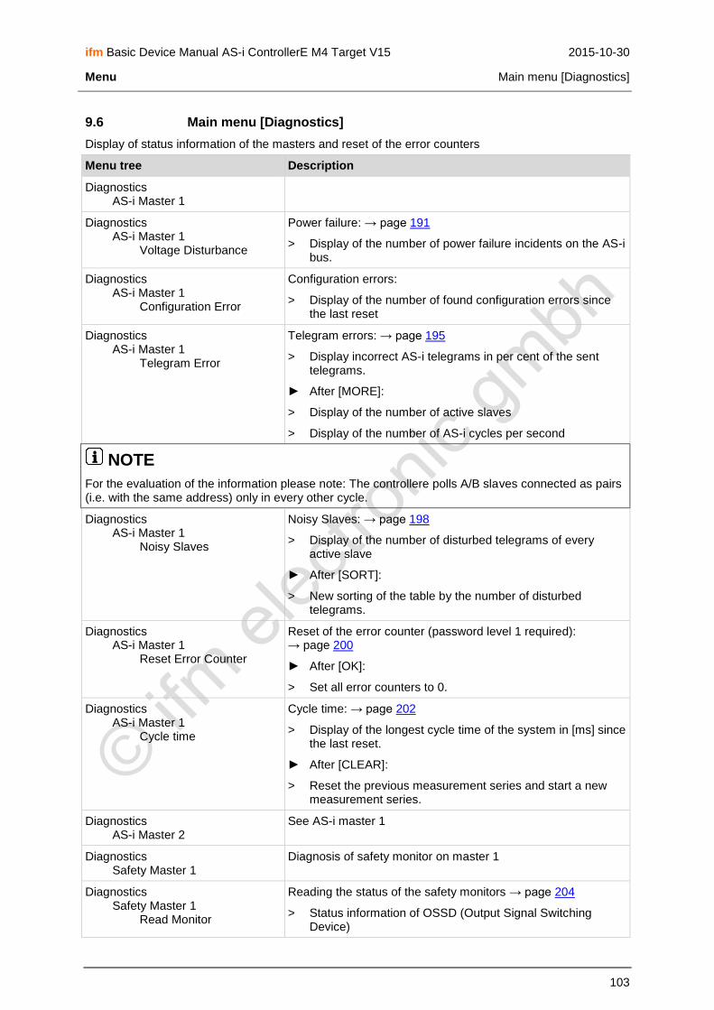
ifm Basic Device Manual AS-i ControllerE M4 Target V15 2015-10-30
Menu Main menu [Diagnostics]
103
9.6 Main menu [Diagnostics]
Display of status information of the masters and reset of the error counters
Menu tree Description
Diagnostics AS-i Master 1
Diagnostics AS-i Master 1 Voltage Disturbance
Power failure: → page 191
> Display of the number of power failure incidents on the AS-i bus.
Diagnostics AS-i Master 1 Configuration Error
Configuration errors:
> Display of the number of found configuration errors since the last reset
Diagnostics AS-i Master 1 Telegram Error
Telegram errors: → page 195
> Display incorrect AS-i telegrams in per cent of the sent telegrams.
► After [MORE]:
> Display of the number of active slaves
> Display of the number of AS-i cycles per second
NOTE
For the evaluation of the information please note: The controllere polls A/B slaves connected as pairs (i.e. with the same address) only in every other cycle.
Diagnostics AS-i Master 1 Noisy Slaves
Noisy Slaves: → page 198
> Display of the number of disturbed telegrams of every active slave
► After [SORT]:
> New sorting of the table by the number of disturbed telegrams.
Diagnostics AS-i Master 1 Reset Error Counter
Reset of the error counter (password level 1 required): → page 200
► After [OK]:
> Set all error counters to 0.
Diagnostics AS-i Master 1 Cycle time
Cycle time: → page 202
> Display of the longest cycle time of the system in [ms] since the last reset.
► After [CLEAR]:
> Reset the previous measurement series and start a new measurement series.
Diagnostics AS-i Master 2
See AS-i master 1
Diagnostics Safety Master 1
Diagnosis of safety monitor on master 1
Diagnostics Safety Master 1 Read Monitor
Reading the status of the safety monitors → page 204
> Status information of OSSD (Output Signal Switching Device)

ifm Basic Device Manual AS-i ControllerE M4 Target V15 2015-10-30
Menu Main menu [Diagnostics]
104
Menu tree Description
Diagnostics Safety Master 1 Trigg. Slave
Reading the status of the safety slaves → page 207
> Status information of the input bits (code sequence)
Diagnostics Safety Master 1 Enable Monitor
Enabling an AS-i slave as safety monitor. Only after this can the controllere exchange the safety-related data with the safety
monitor (special protocol). → page 210
Diagnostics Safety Master 1 Disable Monitor
Disabling an AS-i slave as safety monitor. → page 213
Diagnostics Safety Master 1 Setup Monitor
Setting the diagnosis by enable circuits or by all safety devices → page 216
Diagnostics Safety Master 1 Reset all
Resetting all set diagnostic states of the safety devices → page 219
Diagnostics Safety Master 2
See safety master 1

ifm Basic Device Manual AS-i ControllerE M4 Target V15 2015-10-30
Menu Main menu [Master Setup]
105
9.7 Main menu [Master Setup]
Set master operating modes
Menu tree Description
Master Setup AS-i Master 1
Master setup AS-i master 1
Master Setup AS-i Master 1 Config all
AS-i master 1: configure all (password level 1 required)
Requirements: - Operating mode = configure - No slave with the address 0 on the bus
> Safety query: "Are you sure?"
► After [OK]:
> The controllere checks all connected slaves (only on this
master) and enters them as "projected" in its table.
> The mode remains "configure".
Master Setup AS-i Master 1 Operation Mode
AS-i master 1: operating mode (password level 1 required) → page 116
> Display of the current setting
Master Setup AS-i Master 1 Operation Mode Protect. Mode
Operating mode "protected":
> LED [PROJ] goes out.
> Changes of the slaves are detcted (LED [CONF/PF] lights). Slaves with another projected profile are not activated.
Master Setup AS-i Master 1 Operation Mode Config. Mode
Operating mode "configure":
> LED [PROJ] lights.
> Changes of the slaves are detected (LED [CONF/PF] lights). All connected slaves are active.
Master Setup AS-i Master 1 Autoaddr. Mode
AS-i master 1: "Automatic addressing" mode (password level 1 required)
> Display of the current setting
► Scroll between ON and OFF with [▲] or [▼]
► Adopt with [OK].
Automatic addressing ON: Permits the replaced slave to be assigned the address of the old slave in the protected mode (default)
Automatic addressing OFF: The replaced slave must be manually set to the right address.

ifm Basic Device Manual AS-i ControllerE M4 Target V15 2015-10-30
Menu Main menu [Fieldbus Setup]
106
Menu tree Description
Master Setup AS-i Master 1 Slave Reset
AS-i master 1: slave reset (password level 1 required)
> Display of the current setting
► Scroll between ON and OFF with [▲] or [▼]
► Adopt with [OK].
Slave reset ON: After changing the master to the protected mode the controllere briefly sets all slave outputs to 0 (default).
Slave reset OFF: The status of the slave outputs remains unchanged when switching to another operating mode.
Master Setup AS-i Master 2
See AS-i master 1
9.8 Main menu [Fieldbus Setup]
Setting of fieldbus parameters (password level 1 required)
Menu tree Description
Fieldbus Setup Fieldbus Setup → supplementary device manual fieldbus (option)

ifm Basic Device Manual AS-i ControllerE M4 Target V15 2015-10-30
Menu Main menu [Slave Info]
107
9.9 Main menu [Slave Info]
Display of status information of individual active slaves → page 222
Menu tree Description
Slave Info AS-i Master 1
> Display of the detected slave with the lowest address in the bus.
► Scroll in the addresses of the detected slaves with [▲] or [▼]
> After [OK]: current parameters of the selected slave (depending on the type of slave):
Data of the digital inputs and outputs (binary + hexadecimal)
Data of the analogue channels (decimal)
Entries in the lists of activated / detected / projected slaves with periphery fault
Slave profile configuration
Slave parameters
Number of telegram errors
► Scroll in the addresses of the detected slaves with [▲] or [▼] to display the same parameters of other slaves
► Continue to the next parameters with [MORE].
► Abort with [ESC].
Slave Info AS-i Master 2
See AS-i master 1

ifm Basic Device Manual AS-i ControllerE M4 Target V15 2015-10-30
Menu Main menu [Slave Setup]
108
9.10 Main menu [Slave Setup]
Display or change output data or parameters of individual slaves (password level 2 required)
WARNING
Risk of personal injury! Risk of material damage to the machine/plant! After changing the slave outputs the output values remain unchanged.
The output values only change in the following cases:
Manual new setting of the outputs via Slave Setup
Start of the PLC program - the program processes the outputs
Power off the controllere and restart
► Secure the concerned area.
► Only trained personnel is allowed to set outputs manually.
► Switch the outputs off again immediately after the end of the test.
Menu tree Description
Slave Setup AS-i Master 1
> Display of the detected slave with the lowest address in the bus
► Scroll in the addresses of the detected slaves with [▲] or [▼]
► Select slave address with [OK]
Slave Setup AS-i Master 1 Digital output
> Display of current parameters of the selected slave → page 226
► Change the value of the output signal with [▲] or [▼] and then [SET].
> The line "Current" adopts the setup value and the change is transferred to the outputs as long as the active PLC program in the controllere does not process these outputs.
► Abort with [ ESC].
Slave Setup AS-i Master 1 Parameter value
> Display of current parameters of the selected slave → page 138
► Change the parameter value in the line "Setup" with [▲] or [▼] and transfer it to the slave with [SET].
> If the value or change is not allowed: "Slave data invalid"
► Abort with [ ESC].
Slave Setup AS-i Master 1 Analogue value
> Display of current data of the selected slave (depending on the type of slave): analogue values → page 226
► After [OK]:

ifm Basic Device Manual AS-i ControllerE M4 Target V15 2015-10-30
Menu Main menu [Slave Setup]
109
Menu tree Description
Slave Setup AS-i Master 1 Analogue value Analogue channel 1 Analogue channel 2 Analogue channel 3 Analogue channel 4
► Scroll through the numbers of the analogue channels with [▲] or [▼]
► After [OK]:
> Display of current data of the selected channel.
► Change the value of the analogue channel with [▲] or [▼] and then [SET].
> The line "Current" adopts the setup value and the change is transferred to the outputs as long as the active PLC program in the controllere does not process these outputs.
► Abort with [ ESC].
Slave Setup AS-i Master 2
See AS-i master 1
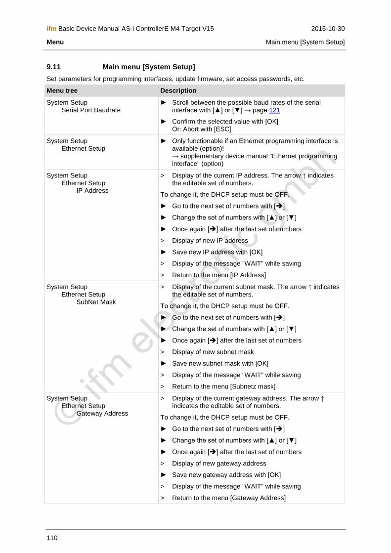
ifm Basic Device Manual AS-i ControllerE M4 Target V15 2015-10-30
Menu Main menu [System Setup]
110
9.11 Main menu [System Setup]
Set parameters for programming interfaces, update firmware, set access passwords, etc.
Menu tree Description
System Setup Serial Port Baudrate
► Scroll between the possible baud rates of the serial interface with [▲] or [▼] → page 121
► Confirm the selected value with [OK] Or: Abort with [ESC].
System Setup Ethernet Setup
► Only functionable if an Ethernet programming interface is available (option)! → supplementary device manual "Ethernet programming interface" (option)
System Setup Ethernet Setup IP Address
> Display of the current IP address. The arrow ↑ indicates the editable set of numbers.
To change it, the DHCP setup must be OFF.
► Go to the next set of numbers with []
► Change the set of numbers with [▲] or [▼]
► Once again [] after the last set of numbers
> Display of new IP address
► Save new IP address with [OK]
> Display of the message "WAIT" while saving
> Return to the menu [IP Address]
System Setup Ethernet Setup SubNet Mask
> Display of the current subnet mask. The arrow ↑ indicates the editable set of numbers.
To change it, the DHCP setup must be OFF.
► Go to the next set of numbers with []
► Change the set of numbers with [▲] or [▼]
► Once again [] after the last set of numbers
> Display of new subnet mask
► Save new subnet mask with [OK]
> Display of the message "WAIT" while saving
> Return to the menu [Subnetz mask]
System Setup Ethernet Setup Gateway Address
> Display of the current gateway address. The arrow ↑ indicates the editable set of numbers.
To change it, the DHCP setup must be OFF.
► Go to the next set of numbers with []
► Change the set of numbers with [▲] or [▼]
► Once again [] after the last set of numbers
> Display of new gateway address
► Save new gateway address with [OK]
> Display of the message "WAIT" while saving
> Return to the menu [Gateway Address]

ifm Basic Device Manual AS-i ControllerE M4 Target V15 2015-10-30
Menu Main menu [System Setup]
111
Menu tree Description
System Setup Ethernet Setup Baudrate
► Scroll in the possible parameters with [▲] or [▼]
► Save new baud rate with [OK]
> Display of the message "WAIT" while saving
> Return to the menu [Baudrate].
System Setup Ethernet Setup Auto Negotiation
Automatic negotiation of the baud rate and transmission (full/half-duplex) between the Ethernet participants:
► Scroll between ON and OFF with [▲] or [▼]
► Adopt with [OK].
> Display of the message "Wait" while saving
> Return to the menu [Auto Negotiation]
System Setup Ethernet Setup DHCP Setup
Automatic assignment of the IP address by an available DHCP server:
► Scroll between ON and OFF with [▲] or [▼]
► Adopt with [OK]
> Display of the message "WAIT" while saving
> Return to the menu [DHCP Setup]
System Setup Ethernet Setup MAC ID
> Display of the manufacturer identification number of the Ethernet participant in the network.
System Setup Modbus Setup
Only functionable if an Ethernet programming interface is available (option)! → supplement to the manual "Ethernet programming interface" (option)
► Scroll between enabling and disabling the Modbus support with [▲] or [▼] (password level 1 required)
System Setup Firmware Update
Update of the firmware (RTS Runtime System Software) (password level 3 required): → page 146
Requirement: PC/laptop with special software connected to serial interface
System Setup Firmware Update Runtime System
Update of the run time system
> Display: "RTS Firmware: Connect to PC – Start now?"
► [OK]
► Start transmission on the PC
> Transmission active
System Setup Firmware Update AS-i Master 1
Update of the AS-i master 1
► [OK]
> Display: "AS-i 1 Firmware: Connect to System – Start now?"
► [OK]
► Start transmission on the PC
> Transmission active

ifm Basic Device Manual AS-i ControllerE M4 Target V15 2015-10-30
Menu Main menu [System Setup]
112
Menu tree Description
System Setup Firmware Update AS-i Master 2
See update of the AS-i master 1
System Setup Password
Prevents unauthorised changes on the controllere with a 4-
digit password. → page 141
> Display: "Password – 0000" An arrow (↑) beneath shows the digit to be edited
► Go to the next digit with []
► Change the digit with [▲] or [▼]
► Once again [] after the last digit
> Display password
► Adopt with [OK] Abort with [ESC]
> Return to the previous menu level
If the password has been entered correctly, the corresponding parameter changes are possible; if the password is wrong they are blocked.
System Setup Factory default
► Start factory setting with [OK] (password level 3 required) → page 144
> Safety query "Are you sure?"
► [OK]
> Reset the controllere to the factory setting. Some changes
will only become effective after the next power-on.
> In the process, PLC programs are not deleted.
> The the process, fieldbus settings are not reset.
> The password is reset to level 1.
System Setup System Errors
System setup errors → page Fehler! Textmarke nicht definiert.
> History memory of the last system errors which must be acknowledged
System Setup System Specials
Special system features (password level 2 required)
System Setup System Specials Fall Back
Switch between FALL BACK VNC ON and FALL BACK VNC OFF
The menu opened by the user is automatically exited if no key is pressed after a defined period.
System Setup System Specials RTS Error
Switch between RTS ERROR ON and RTS ERROR OFF
The display of the Rxx system messages can be deactivated by means of this setting.
System Setup System Specials Bitmap Manual
> Display of saved background images
► Scroll with the keys [▲] or [▼]
► Abort with the right key
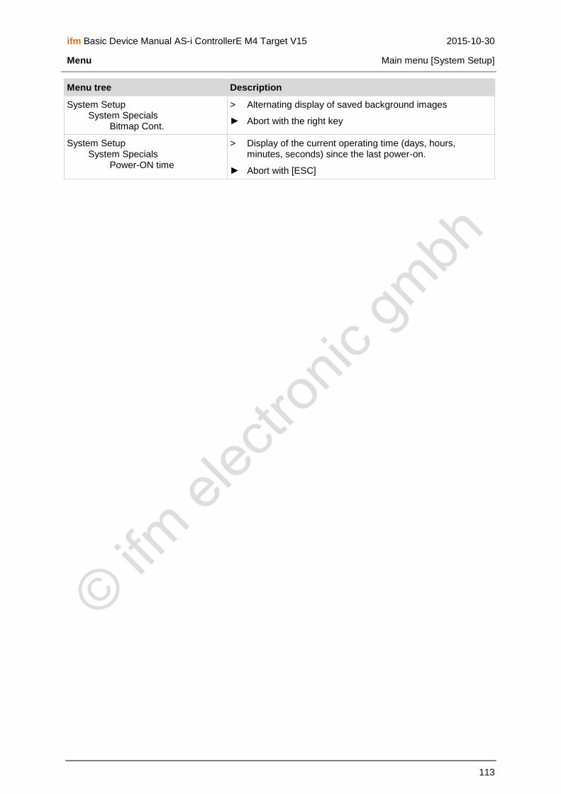
ifm Basic Device Manual AS-i ControllerE M4 Target V15 2015-10-30
Menu Main menu [System Setup]
113
Menu tree Description
System Setup System Specials Bitmap Cont.
> Alternating display of saved background images
► Abort with the right key
System Setup System Specials Power-ON time
> Display of the current operating time (days, hours, minutes, seconds) since the last power-on.
► Abort with [ESC]

ifm Basic Device Manual AS-i ControllerE M4 Target V15 2015-10-30
Menu Main menu [System Info]
114
9.12 Main menu [System Info]
Display all system parameters
Menu tree Description
System Info > Display of all system parameters: → page 233
Hardware version RTS runtime system firmware version AS-i master 1 firmware version AS-i master 2 firmware version Fieldbus system version
RTS checksum Consistency checksum Linux kernel version Linux RAM disc version
Device serial number
From here display only in the administrator mode (protected by password level 3):
Designers Developers Programmers
Admin Info (permanently updated): RTS cycles 100 ms each Max. RTS response time [ms] PLC cycle time [ms] Max. PLC cycle time [ms]
► Delete cycle time values with [CLEAR]
► Continue to scroll in the parameter list with [MORE]
► Back to the start menu with [MENU] or [ESC]

ifm Basic Device Manual AS-i ControllerE M4 Target V15 2015-10-30
Operating modes Which operating modes are available for the AS-i master?
115
10 Operating modes
In this chapter you will learn (separately for AS-i master and PLC):
Which operating modes are possible?
What do the operating modes mean?
Which operating mode should be used when?
How are the operating modes selected?
10.1 Which operating modes are available for the AS-i master?
The master of the controllere can be used in the following operating modes:
Operating mode Description Use
Operation Mode Protected mode
> LED [PROJ] is out.
> New slaves are only activated if they have been correctly projected before.
If no effect on the AS-i system is requested by removing or adding slaves.
Changes to the projected constellation of the slaves are indicated as an error message:
"Slave X not present" or "Slave X not projected"
When replacing a faulty slave by an identical slave with the address 0 the system detects and adopts the new slave and assigns to it the address of the faulty slave.
Config. Mode Configure
> LED PROJ lights.
> New slaves are immediately detected.
Only makes sense in case of planned changes to the AS-i system.
In principle, changes to the slaves which are connected to the master via AS-i are immediately detected. The LED [CONF/PF] lights as soon as there is a change compared to the projected status.

ifm Basic Device Manual AS-i ControllerE M4 Target V15 2015-10-30
Operating modes How are the operating modes for the AS-i master selected?
116
10.2 How are the operating modes for the AS-i master selected?
[MENU] > [Master Setup] > select master > [Operation Mode] > select mode > [OK]
1.
► Press [MENU] MMEENNUU 0 UUSSEERR
2. Quick Setup
PLC Setup
Slave Lists
► Press [▼] to scroll to [Master Setup] OOKK 1
▲ ▼ EESSCC
3. Address Slave
Diagnostics
Master Setup
► Select [Master Setup] with [OK]. OOKK 1
▲ ▼ EESSCC
4. SSeettuupp ooff
AS-i Master 1
AS-i Master 2
► If necessary, press [▼] to scroll to [Master 2] OOKK 43
▲ ▼ EESSCC

ifm Basic Device Manual AS-i ControllerE M4 Target V15 2015-10-30
Operating modes How are the operating modes for the AS-i master selected?
117
5. SSeettuupp ooff
AS-i Master 1
AS-i Master 2
► Select AS-i master with [OK]. OOKK 43
▲ ▼ EESSCC
6. AASS--ii MMaasstteerr 11
Operation Mode
Autoaddr. Mode
► Select [Operation Mode] with [OK]. OOKK 44
▲ ▼ EESSCC
7. AASS--ii MMaasstteerr 11
Protect. Mode
Config. Mode
> The marking shows the current operating mode.
► Press [▲] or [▼] to scroll to other operating mode OOKK
47 ▲ ▼ EESSCC
8. AASS--ii MMaasstteerr 11
Protect. Mode
Config. Mode
► Activate the selected operating mode with [OK]. OOKK 47
▲ ▼ EESSCC
10. AASS--ii MMaasstteerr 11
Operation Mode
Autoaddr. Mode
> LED [PROJ] lights when the "config" mode is active.
> LED [PROJ] is out when the "protected" mode is active.
► Press [ESC] several times to return to the start screen
> That's it.
OOKK 44
▲ ▼ EESSCC

ifm Basic Device Manual AS-i ControllerE M4 Target V15 2015-10-30
Operating modes Which operating modes are available for the PLC in the controllere?
118
10.3 Which operating modes are available for the PLC in the controllere?
Operating mode Description Use
Run PLC program start
> The PLC program stored in the controllere is processed.
> LED [PLC RUN] lights
Controlling of the inputs and outputs on the controllere by the PLC program
Stop PLC program stop
> The PLC program stored in the controllere is stopped.
> LED [PLC RUN] flashes
Changes to the PLC program or to the slaves
Gateway Controllere as gateway
> LED [PLC RUN] goes out
The host on the fieldbus (option) directly accesses the actuators on the AS-i bus via the controllere.
NOTE
During changes to the PLC program or to the slaves the PLC program should be stopped to avoid malfunctions.

ifm Basic Device Manual AS-i ControllerE M4 Target V15 2015-10-30
Operating modes How are the operating modes for the PLC selected?
119
10.4 How are the operating modes for the PLC selected?
[MENU] > [PLC Setup] > [PLC Settings] > select operating mode > [OK]
1.
► Press [MENU] MMEENNUU 0 UUSSEERR
2. Quick Setup
PLC Setup
Slave Lists
► Press [▼] to scroll to [PLC Setup] OOKK 1
▲ ▼ EESSCC
3. Quick Setup
PLC Setup
Slave Lists
► Select [PLC Setup] with [OK] OOKK 1
▲ ▼ EESSCC
4. PPLLCC SSeettuupp
PLC Settings
PLC Info
► Select [PC Settings] with [OK] OOKK 42
▲ ▼ EESSCC

ifm Basic Device Manual AS-i ControllerE M4 Target V15 2015-10-30
Operating modes How are the operating modes for the PLC selected?
120
5. PPLLCC SSeettttiinnggss
Run
Stop
> The marking shows the current operating mode.
► Press [▲] or [▼] to scroll to other operating mode OOKK
11 ▲ ▼ EESSCC
6. PPLLCC SSeettttiinnggss
Run
Stop
► Activate the selected operating mode with [OK] OOKK 11
▲ ▼ EESSCC
NOTE
If no PLC program is loaded in the controllere, an error message appears if you try to switch the PLC
to the "Run" mode.
> The PLC goes into the operating mode "Stop".
7. Quick Setup
PLC Setup
Slave Lists
> LED [PLC RUN] lights when PLC program is running.
> LED [PLC RUN] flashes when PLC is stopped.
> LED [PLC RUN] is out when controllere operates as gateway.
► Return to the start screen with [ESC]
> That's it.
OOKK 1
▲ ▼ EESSCC
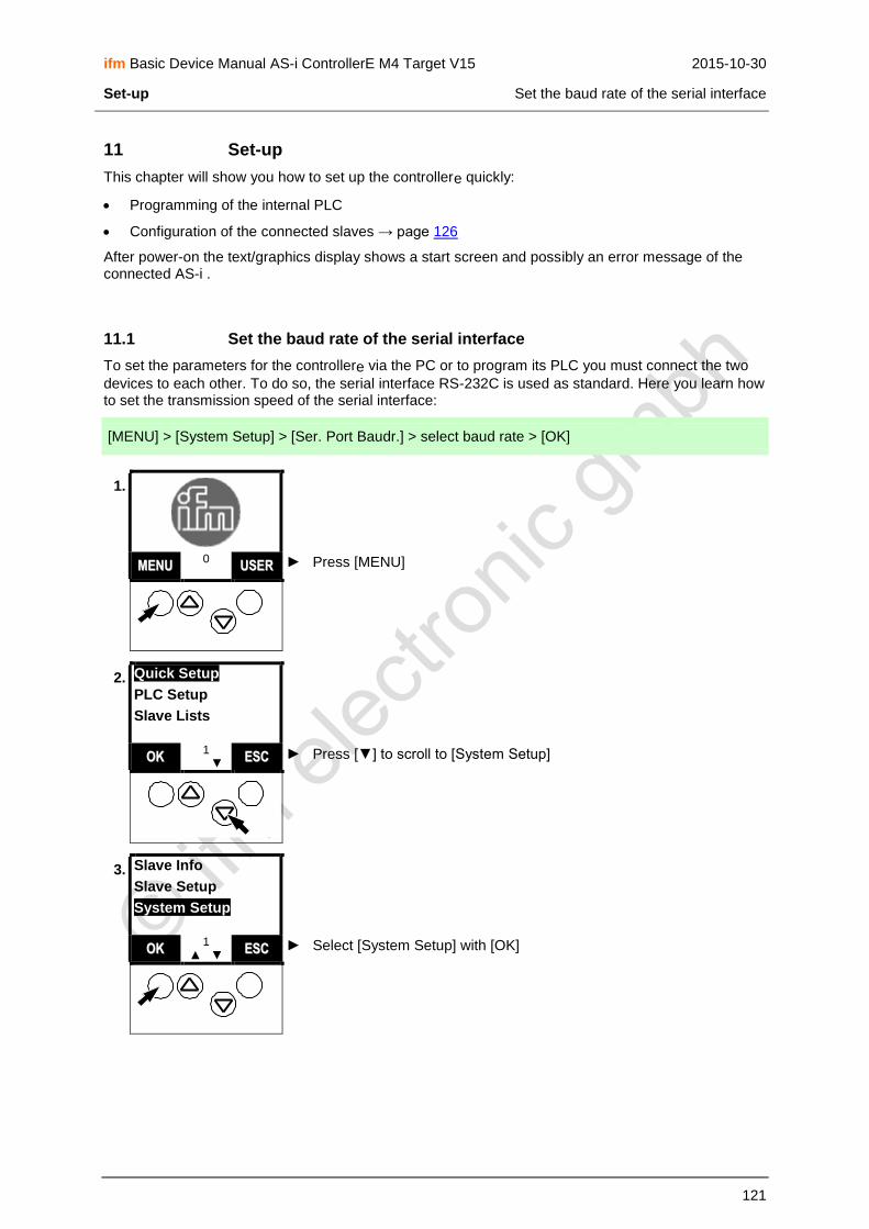
ifm Basic Device Manual AS-i ControllerE M4 Target V15 2015-10-30
Set-up Set the baud rate of the serial interface
121
11 Set-up
This chapter will show you how to set up the controllere quickly:
Programming of the internal PLC
Configuration of the connected slaves → page 126
After power-on the text/graphics display shows a start screen and possibly an error message of the connected AS-i .
11.1 Set the baud rate of the serial interface
To set the parameters for the controllere via the PC or to program its PLC you must connect the two
devices to each other. To do so, the serial interface RS-232C is used as standard. Here you learn how to set the transmission speed of the serial interface:
[MENU] > [System Setup] > [Ser. Port Baudr.] > select baud rate > [OK]
1.
► Press [MENU] MMEENNUU 0 UUSSEERR
2. Quick Setup
PLC Setup
Slave Lists
► Press [▼] to scroll to [System Setup] OOKK 1
▲ ▼ EESSCC
3. Slave Info
Slave Setup
System Setup
► Select [System Setup] with [OK] OOKK 1
▲ ▼ EESSCC

ifm Basic Device Manual AS-i ControllerE M4 Target V15 2015-10-30
Set-up Set the baud rate of the serial interface
122
4. SSyysstteemm SSeettuupp
Ser. Port Baudr.
Ethernet Setup
► Select [Ser. Port Baudr.] with [OK] OOKK 33
▲ ▼ EESSCC
5. RRSS223322 BBaauuddrraattee
111155220000
5577660000
> Display of current value
► Press [▲] or [▼] to scroll to the requested baud rate: Selection:
115 200 baud (factory setting)
57 600
38 400
19 200
9 600
4 800 or
2 400 Baud*
OOKK 34
▲ ▼ EESSCC
NOTE
Select the quickest connection which is possible without any problems with the devices used (PC, connection cable, controllere) and the electromagnetic interference on site.
*) The setting 2 400 baud is reserved for HMIs and displays.
6. RRSS223322 BBaauuddrraattee
111155220000
5577660000
► Select set baud rate with [OK] OOKK 34
▲ ▼ EESSCC
7. SSyysstteemm SSeettuupp
Ser. Port Baudr.
Ethernet Setup > Return to screen 33
► Press [ESC] twice to return to the start screen
> That's it!
OOKK 33
▲ ▼ EESSCC

ifm Basic Device Manual AS-i ControllerE M4 Target V15 2015-10-30
Set-up Set the baud rate of the serial interface
123
NOTE
► Set the same value on the PC! → page 124, chapter RS-232C
11.1.1 Install target for the controllere
► Install the current target for the AS-i controllere, if not yet done:
1. ► Click on [Start] > [Programs] > [CoDeSys] > [InstallTarget] on the PC
2.
► Click on [Open] to open the installation file "Target Information File" (*.TNF)
3.
► Select the source directory for the new target (from the installation CD) and confirm with [Open]
4.
► Mark the target for the controllere (→
figure)
► Start installation with [Install]
> Message "The installation directory does not exist. Create?" OR: Message "The target ... already exists. Overwrite it?"
► Confirm with [Yes]
> Target is being installed
► Finish with [Close]
> That's it! The new target is installed.

ifm Basic Device Manual AS-i ControllerE M4 Target V15 2015-10-30
Set-up Set the baud rate of the serial interface
124
11.1.2 Connect the programming device
RS-232C
To connect the PC with the programming software to the serial interface RS-232C of the controllere,
you need the programming cable with 1 Sub-D-9 connector (female) and 1 RJ11 connector: → Article no. E70320
► Connect the PC to the controllere using the above-mentioned cable
► Start the programming software CoDeSys® 2.3 on the PC
► Create a new project in CoDeSys®
► Set target system:
1.
► Click on the symbol [▼]
2.
► Select a valid target for the controllere
and confirm with [OK]
3.
► Confirm with [OK]
4.
► Confirm the new POU "PLC_PRG" with [OK]
5.
► Replace "???" by "TRUE" in the first network
► PC key [Enter]
> The first "program" is provisionally finished.
6.
► Menu sequence [Online] > [Communication Parameters]
► Mark the uppermost line in the column [Channels]
► Click [New…]

ifm Basic Device Manual AS-i ControllerE M4 Target V15 2015-10-30
Set-up Set the baud rate of the serial interface
125
7.
► Enter "RS 232" as name
► Select [Serial (RS232)] as device
► Confirm with [OK]
8.
► Double-click to change the baud rate step by step until the value corresponds to the setting in the controllere
→ page 121
► Adopt with [ENTER]
► Confirm with [OK]
► Test connection with the menu sequence [Online] > [Login]
> If response "Communication Error", then:
► change the baud rate step by step and test communication again
> If there is a connection between the PC and the controllere, then message →
figure
In the supplementary device manual "PLC programming with CoDeSys® 2.3" more detailed information about the use of the programming system "CoDeSys for Automation Alliance" is given. This manual can be downloaded free of charge from ifm's website at: → www.ifm.com > Select country/language > [Service] > [Download] > [Bus system AS-Interface]
Ethernet (option)
To connect the PC with the programming software directly to the optional Ethernet programming interface of the controllere, you need a cross-over patch cable Cat5 with RJ45 connector on both
sides. → article no. EC2080
Description of the Ethernet programming interface: → separate supplementary manual for this device manual.

ifm Basic Device Manual AS-i ControllerE M4 Target V15 2015-10-30
Set-up Configuration
126
11.2 Configuration
In this chapter you will learn the methods how to address slaves using the controllere.
NOTE
Every address is allowed in the system only once so that the AS-i master can communicate with every slave individually.
Slaves with the address 0 do not operate on the bus.
The manufacturers of AS-i slaves always deliver their devices with the address 0.
The controllere displays an error message and does not process slaves with wrong addresses or
addresses which have been assigned twice.
11.2.1 Permissible slave addresses
Single slaves (0), 1...31
A/B slaves (0A), 1A...31A, 1B...31B *)
*) The address 0B is not possible.
If an address has been assigned to a single slave, this address must not be assigned as an A or B address. Addresses assigned to A/B slaves must not be assigned to single slaves. Example of non permissible address assignment: 17, 17A
If an address has been assigned to an A slave, this address may also be assigned as B address. A/B slaves share one address number. Example of permissible address assignment: 17A, 17B
Maximum number of slaves per master: 31 single slaves or 62 A/B slaves

ifm Basic Device Manual AS-i ControllerE M4 Target V15 2015-10-30
Set-up Configuration
127
11.2.2 Automatic addressing of individual slaves
Now address the slaves. This is possible by means of the keys and the text/graphics display on the controllere. In the mode "Easy Startup" the controllere can address the slaves automatically in rising
order if the slaves are connected to the bus one after the other.
NOTE
However, this automatic process only works without problems if the slave to be connected has the address 0! If the slave has already been used in another system, it will probably already have an address other than 0.
In such a case, the controllere does not react to the connection of the new slave. This slave is not
automatically addressed.
Then → page 130, chapter Manual slave addressing.
Password level 1 required → page 142, chapter Password setting
[MENU] > [Address Slave] > [Easy Startup] > select master > connect slave > [ESC]
1.
► Press [MENU] MMEENNUU 0 UUSSEERR
2. Quick Setup
PLC Setup
Slave Lists
► Press [▼] to scroll to [Address Slave] OOKK 1
▲ ▼ EESSCC
3. PLC Setup
Slave Lists
Address Slave
► Select [Address Slave] with [OK] OOKK 1
▲ ▼ EESSCC

ifm Basic Device Manual AS-i ControllerE M4 Target V15 2015-10-30
Set-up Configuration
128
4. SSllaavvee
Change Address
Easy Startup
► Press [▼] to scroll to [Easy Startup] OOKK 12
▲ ▼ EESSCC
5. SSllaavvee
Change Address
Easy Startup
► Select [Easy Startup] with [OK] OOKK 12
▲ ▼ EESSCC
6. EEaassyy SSttaarrttuupp ooff
AS-i Master 1
AS-i Master 2
► If necessary, press [▼] to scroll to AS-i master 2 OOKK 22
▲ ▼ EESSCC
7. EEaassyy SSttaarrttuupp ooff
AS-i Master 1
AS-i Master 2
► Select requested AS-i master with [OK] OOKK 22
▲ ▼ EESSCC
8. EEaassyy SSttaarrttuupp
Master 1 waiting for slave 0 Last Address: Next Address: 1 / 1A > The controllere is waiting for a slave with the address 0 to be
activated on or connected to master 1.
► Take a slave which still has the address 0 and connect it to the AS-i bus or activate it.
23 EESSCC

ifm Basic Device Manual AS-i ControllerE M4 Target V15 2015-10-30
Set-up Configuration
129
9. EEaassyy SSttaarrttuupp
Master 1 waiting for slave 0 Last Address: 1 Next Address: 2 / 2A
> The controllere automatically assigns the lowest available address to
this slave
> The controllere displays the address assigned to the new slave and,
below, the next available slave address.
> LED [PWR/COM] no longer flashes, but lights: At least one active slave is now correctly detected.
> LED CONF/PF lights: There is (at least) one new slave on the bus which the controllere does not yet have in its projection list.
When all slaves have been addressed:
► Return to the start screen with [ESC]
23 ! EESSCC
NOTE
► Only connect one new slave at a time in the mode "Easy Startup"!
> When the controllere finished the integration of the new slave, the display "Waiting for Slave 0" is
shown again.
► Note the address assigned under "Last address" for this slave.
► Then you can connect the next slave with the address 0.

ifm Basic Device Manual AS-i ControllerE M4 Target V15 2015-10-30
Set-up Configuration
130
11.2.3 Manual slave addressing
The old slave address is not 0? The automatic procedure described above (→ page 127), however, only works without problems if the slaves to be connected have the address 0! If the slaves have already been used in another system, the slaves probably already have another address. In such a case, the controllere does not react to the connection of the new slave.
► Remove these slaves from the system.
In the following section we will show you how the addresses of the devices can be changed.
E25 ASi1
Config. Error
► End automatic addressing: Press [ESC] several times to return to the start screen (→ figure). MMEENNUU
1/2 ▲ ! ▼ UUSSEERR
You would like to integrate a slave in the AS-i bus which has already been assigned an address but now needs a new address?
Prerequisites:
Neither the "old" nor the new address of the slave is allowed on the bus.
Connecting a slave with the address 0 to the AS-i bus is not allowed.
► If necessary, temporarily remove the existing slave with the correct "old" address from the bus.
► Install or activate the new slave on the bus.
NOTE
Password level 1 required → page 142, chapter Password setting
[MENU] > [Address Slave] > [Change Address] > select master > select old slave address > [OK] > select new slave address > [OK] > [MORE] orr [ESC]
1. E25 ASi1
Config. Error
> The display on the left appears instead of the ifm start screen: "Config. error"
> LED [CONF/PF] lights
Cause: There is (at least) one new slave on the bus which is not yet in the projection list of the the controllere.
Note: error description → page 239, chapter Error description
► Press [MENU]
MMEENNUU 1/2
▲ ! ▼ UUSSEERR

ifm Basic Device Manual AS-i ControllerE M4 Target V15 2015-10-30
Set-up Configuration
131
2. Quick Setup
PLC Setup
Slave Lists
► Press [▼] to scroll to [Address Slave] OOKK 1
▲ ! ▼ EESSCC
3. PLC Setup
Slave Lists
Address Slave
► Select [Address Slave] with [OK] OOKK 1
▲ ! ▼ EESSCC
4. SSllaavvee
Change Address
Easy Startup
► Select [Change Address] with [OK] OOKK 12
▲ ! ▼ EESSCC
5. AAddddrreessss SSllaavvee ooff
AS-i Master 1
AS-i Master 2
► If necessary, press [▼] to scroll to AS-i master 2 OOKK 13
▲ ! ▼ EESSCC
6. AAddddrreessss SSllaavvee ooff
AS-i Master 1
AS-i Master 2
► Select requested AS-i master with [OK] OOKK 13
▲ ! ▼ EESSCC

ifm Basic Device Manual AS-i ControllerE M4 Target V15 2015-10-30
Set-up Configuration
132
7. CCuurrrr.. SSllaavvee AAddddrr..
AASS--ii MMaasstteerr 11
66AA > Display of the lowest found valid slave address
► Press [▲] or [▼] to scroll to the slave whose address is to be changed
OOKK 14
▲ ! ▼ EESSCC
8. CCuurrrr.. SSllaavvee AAddddrr..
AASS--ii MMaasstteerr 11
2200
► Select the requested slave with [OK] OOKK 14
▲ ! ▼ EESSCC
9. NNeeww SSllaavvee AAddddrr..
AASS--ii MMaasstteerr 11
00 > Display of neutral slave address 0
► Press [▲] to scroll to the requested slave address OOKK
15 ▲ ! ▼ EESSCC
10. NNeeww SSllaavvee AAddddrr..
AASS--ii MMaasstteerr 11
55
► Select new slave address with [OK] OOKK 15
▲ ! ▼ EESSCC
11. CChhaannggee AAddddrreessss
MMaasstteerr 11
Cur. Slave Addr. 20 New Slave Addr. 5 > Display of old and new slave address
► Confirm the new slave address with [OK] OOKK
16 ! EESSCC

ifm Basic Device Manual AS-i ControllerE M4 Target V15 2015-10-30
Set-up Configuration
133
12. AAddddrreessssiinngg ddoonnee
Master 1 Old Slave Addr. 20 New Slave Addr. 5
> Display of the message "WAIT" while saving
> Display of the change made (→ figure)
> LED [CONF/PF] lights: configuration error
► Press [MORE] to repeat steps 7 to 12 for another slave whose address is to be changed
► Finish slave addressing with [ESC]
NNEEXXTT 17 ! EESSCC
13. AAddddrreessss SSllaavvee ooff
AS-i Master 1
AS-i Master 2
► Return to the start screen with [ESC] OOKK 13
▲ ! ▼ EESSCC
14. E25 ASi1
Config. Error
> The display on the left appears instead of the ifm start screen: "configuration error"
In the next section we will show you how to finish the configuration.
MMEENNUU 1/2
▲ ! ▼ UUSSEERR

ifm Basic Device Manual AS-i ControllerE M4 Target V15 2015-10-30
Set-up Configuration
134
11.2.4 Finish configuration
NOTE
Now all slaves are present on the bus with the correct address.
But the error message ("!") keeps on flashing and the LED [CONF/PF] lights?
Cause: The controllere detected all slaves on the bus but the slaves are not yet - at least not all
slaves - in the "list of projected slaves" LPS.
This means: The error message "Config. Error" is displayed as long as there is a difference between the detected and configured slaves.
Help: In the mode "Quick Setup" enter all detected slaves in the configuration list by pressing a key.
Password level 1 required → page 142, chapter Password setting
[MENU] > [Slave Lists] > select master > [Detected Slaves]
1. E25 ASi1
Config. Error
> The display on the left appears instead of the ifm start screen: "Config. Error"
► Press the key [MENU]
MMEENNUU 1/2
▲ ! ▼ UUSSEERR
2. PLC Setup
Slave Lists
Address Slave > The controllere shows the last used menu item
► Press [▲] to scroll to [Slave Lists] Reason: Check the configuration made so far in the list of detected slaves LDS.
OOKK 1
▲ ! ▼ EESSCC
3. PLC Setup
Slave Lists
Address Slave
► Select [Slave Lists] with [OK] OOKK 1
▲ ! ▼ EESSCC

ifm Basic Device Manual AS-i ControllerE M4 Target V15 2015-10-30
Set-up Configuration
135
4. SSllaavvee lliisstt ooff
AS-i Master 1
AS-i Master 2
► If necessary, press [▼] to scroll to master 2 OOKK 2
▲ ! ▼ EESSCC
5. SSllaavvee lliisstt ooff
AS-i Master 1
AS-i Master 2
► Select requested master with [OK] OOKK 2
▲ ! ▼ EESSCC
6. Detect. Sl. ASi1
Project. Sl. ASi1
Activ. Sl. ASi1
► Select [Detected Slaves] with [OK] OOKK 91
▲ ! ▼ EESSCC
7. Detect. Sl. ASi1
0 1 2 3 4 5 A . . . . . . B . . . . . . S . . . . . .
> A table of detected slaves is displayed. Here: no slaves have been detected on master 1 with the addresses 0 to 5.
► If necessary, press [▲] to scroll to the next address block
3
▲ ! ▼ EESSCC
8. Detect. Sl. ASi1
6 7 8 9 10 11 A ● - . - . . B - - . - . . S - ● . ● . .
> A table of detected slaves is displayed. In this example:
an A/B slave has been detected as A slave at the address 6
a single slave has been detected at the addresses 7 and 9
► Check found slave addresses and compare them to the draft
► If necessary, press [▲] to scroll to the next address block
3
▲ ! ▼ EESSCC

ifm Basic Device Manual AS-i ControllerE M4 Target V15 2015-10-30
Set-up Configuration
136
9. Detect. Sl. ASi1
6 7 8 9 10 11 A ● - . - . . B - - . - . . S - ● . ● . .
If all detected slaves are to be entered in the configuration list:
► Press [ESC] three times to return to the menu [Slave Lists] (continue → below)
If incorrect slave addresses are to be reassigned: → page 130, chapter Manual slave addressing
3
▲ ! ▼ EESSCC
Enter detected slaves in the configuration list
[Quick Setup] > [Config. all] > [OK]
10. Quick Setup
PLC Setup
Slave Lists > The controllere shows the last used menu item
► Press [▲] to scroll to [Quick Setup] Reason: Enter all detected slaves in the configuration list by pressing a key.
OOKK 1
▲ ! ▼ EESSCC
11. Quick Setup
PLC Setup
Slave Lists
► Select [Quick Setup] with [OK] OOKK 1
▲ ! ▼ EESSCC
12. QQuuiicckk SSeettuupp
Config. all
Fieldbus Setup
► Select [Config. all] with [OK] OOKK 27
▲ ! ▼ EESSCC

ifm Basic Device Manual AS-i ControllerE M4 Target V15 2015-10-30
Set-up Configuration
137
13. CCoonnffiigg.. aallll
MMaasstteerr 11//22
AArree yyoouu ssuurree?? > Display of safety query
► Confirm with [OK]
OOKK 28 ! EESSCC
14. QQuuiicckk SSeettuupp
Config. all
Fieldbus Setup
> Display of the message "WAIT" while saving
> Error message "!" goes out
> The display on the left appears
> Red LED [CONF/PF] goes out
> Yellow LED [PROJ] goes out because the device now automatically activates the "protected mode"
► Press [ESC] twice to return to the start screen
> That's it!
OOKK 27
▲ ▼ EESSCC

ifm Basic Device Manual AS-i ControllerE M4 Target V15 2015-10-30
Set-up Change slave parameter data
138
11.3 Change slave parameter data
The default parameter value for the slaves is "0Fh".
Example for a useful parameter change: Unused analogue input channels generate a periphery fault of the module. By changing parameters you can block unused channels so that the module does not trigger a periphery fault.
Please note the corresponding remarks in the instructions of the modules.
NOTE
Password level 2 required → page 142, chapter Password setting Changed values are not adopted in case of a wrong password level
[MENU] > [Slave Setup] > select master > select slave > [Parameter value] > change parameter value > [SET]
1.
► Press [MENU] MMEENNUU 0 UUSSEERR
2. Quick Setup
PLC Setup
Slave Lists
► Press [▼] to scroll to [Slave Setup] OOKK 1
▲ ▼ EESSCC
3. Fieldbus Setup
Slave Info
Slave Setup
► Select [Slave Setup] with [OK] OOKK 1
▲ ▼ EESSCC
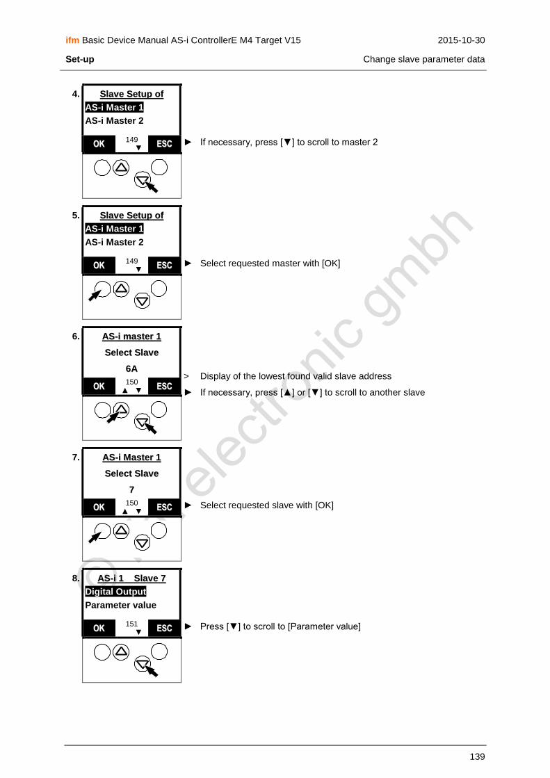
ifm Basic Device Manual AS-i ControllerE M4 Target V15 2015-10-30
Set-up Change slave parameter data
139
4. SSllaavvee SSeettuupp ooff
AS-i Master 1
AS-i Master 2
► If necessary, press [▼] to scroll to master 2 OOKK 149
▲ ▼ EESSCC
5. SSllaavvee SSeettuupp ooff
AS-i Master 1
AS-i Master 2
► Select requested master with [OK] OOKK 149
▲ ▼ EESSCC
6. AASS--ii mmaasstteerr 11
SSeelleecctt SSllaavvee
66AA > Display of the lowest found valid slave address
► If necessary, press [▲] or [▼] to scroll to another slave OOKK
150 ▲ ▼ EESSCC
7. AASS--ii MMaasstteerr 11
SSeelleecctt SSllaavvee
77
► Select requested slave with [OK] OOKK 150
▲ ▼ EESSCC
8. AASS--ii 11 SSllaavvee 77
Digital Output
Parameter value
► Press [▼] to scroll to [Parameter value] OOKK 151
▲ ▼ EESSCC

ifm Basic Device Manual AS-i ControllerE M4 Target V15 2015-10-30
Set-up Change slave parameter data
140
9. AASS--ii 11 SSllaavvee 77
Digital Output
Parameter value
► Select [Parameter value] with [OK] OOKK 151
▲ ▼ EESSCC
10. PPaarraammeetteerr vvaalluuee
AASS--ii 11 SSllaavvee 77
Current: 1111 [ 0Fh ] Setup: 1111 [ 0Fh ] > Display of current and setup parameter values as binary value and
hex value
► Press [▲] or [▼] to set the parameter setup value
SSEETT 154
▲ ▼ EESSCC
11. PPaarraammeetteerr vvaalluuee
AASS--ii 11 SSllaavvee 77
Current: 1111 [ 0Fh ] Setup: 1001 [ 09h ]
► Save new parameter data on the slave with [SET] Keep the key [SET] pressed until the change has been made! SSEETT
154 ▲ ▼ EESSCC
12. PPaarraammeetteerr vvaalluuee
AASS--ii 11 SSllaavvee 77
Current: 1001 [ 09h ] Setup: 1001 [ 09h ]
> Setup value of the parameter data is copied to the current parameter data
If the setup value of the parameter data for this slave is not permitted:
> Display of error message: "Invalid slave data"
► Repeat steps 10...12 with corrected values
► Press [ESC] five times to return to the start screen
► That's it!
SSEETT 154
▲ ▼ EESSCC

ifm Basic Device Manual AS-i ControllerE M4 Target V15 2015-10-30
Set-up Password protection
141
11.4 Password protection
11.4.1 General
In the menu [System Setup] in the menu item [Password] the operation can be restricted or enabled. On delivery, the device is in the user mode (= password level 1). By entering an invalid password (e.g. 1000) all menu items which can change settings are disabled. This disabling is the password level 0 (end user mode).
WARNING
Risk for persons and plant/machine by access of unauthorised users to special menus of the controllere.
► Change the password to level 0 again as soon as the work in a higher password level has been completed. → page 142, chapter Password setting
11.4.2 Password levels
Password level Operating mode Password Note
0 end user mode as required
1 user mode CE01 factory setting
2 service mode E02C
Main menu 2nd menu level Required password level
Quick Setup All 1
PLC Setup all 1
Address Slave All 1
Diagnostics Reset Error Counter 1
Master Setup Config all 1
Master Setup Operation Mode 1
Master Setup Autoadr. Mode 1
Master Setup Slave Reset 1
Fieldbus Setup All 1
System Setup Modbus Setup 1
System Setup Firmware Update 3 *)
System Setup Factory default 3 *)
System Setup System Specials 2
System Info Admin Info 3 *)
Slave Setup All 2
All other menus All 0
*) Please contact your AS-i sales specialist if you want to work with the password level 3.
The set password is immediately valid when entered and remains effective until the setting is changed.

ifm Basic Device Manual AS-i ControllerE M4 Target V15 2015-10-30
Set-up Password protection
142
11.4.3 Password setting
[MENU] > [System Setup] > [Password] > change password > [OK]
1.
► Press [MENU] MMEENNUU 0 UUSSEERR
2. Quick Setup
PLC Setup
Slave Lists
► Press [▼] to scroll to [System Setup] OOKK 1
▲ ▼ EESSCC
3. Slave Info
Slave Setup
System Setup
► Select [System Setup] with [OK] OOKK 1
▲ ▼ EESSCC
4. SSyysstteemm SSeettuupp
Ser. Port Baudr.
Ethernet Setup
► Press [▼] to scroll to [Password] OOKK 33
▲ ▼ EESSCC

ifm Basic Device Manual AS-i ControllerE M4 Target V15 2015-10-30
Set-up Password protection
143
5. SSyysstteemm SSeettuupp
Firmware Update
Password
► Select [Password] with [OK] OOKK 33
▲ ▼ EESSCC
6. PPaasssswwoorrdd
00000000
.. > Display password "0000"
The arrow points to the digit which can be changed
► Press [▲] or [▼] to change the digit in the range 0...F
35 EESSCC
7. PPaasssswwoorrdd
33000000
.. > Display of password changed so far
► Move to the next digit with []
35 EESSCC
8. PPaasssswwoorrdd
33000000
.. > Display of password changed so far
The arrow points to the digit which can be changed
► Repeat steps 6...7 for all digits
35 EESSCC
9. PPaasssswwoorrdd
33EE1122
► Set new password with [OK]
NOTE The set password is immediately valid when entered and remains effective until the setting is changed.
OOKK 35 EESSCC

ifm Basic Device Manual AS-i ControllerE M4 Target V15 2015-10-30
Set-up Reset to factory settings
144
11.5 Reset to factory settings
You work with a used controllere (e.g. from a test project). You want to restore the factory settings of
the controllere to prepare it for the new project?
NOTE
Password level 3 required → page 142, chapter Password setting For the administrator mode please contact your AS-i sales specialist.
[MENU] > [System Setup] > [Factory default] > 2x [OK]
1.
► Press [MENU] MMEENNUU 0 UUSSEERR
2. Quick Setup
PLC Setup
Slave Lists
► Press [▼] to scroll to [System Setup] OOKK 1
▲ ▼ EESSCC
3. Slave Info
Slave Setup
System Setup
► Select [System Setup] with [OK] OOKK 1
▲ ▼ EESSCC

ifm Basic Device Manual AS-i ControllerE M4 Target V15 2015-10-30
Set-up Reset to factory settings
145
4. SSyysstteemm SSeettuupp
Ser. Port Baudr.
Ethernet Setup
► Press [▼] to scroll to [Factory default] OOKK 33
▲ ▼ EESSCC
5. SSyysstteemm SSeettuupp
Password
Factory default
► Select [Factory default] with [OK] OOKK 33
▲ ▼ EESSCC
6. SSeett ffaaccttoorryy
ddeeffaauulltt
AArree yyoouu ssuurree?? > Display of safety query
► Confirm with [OK]
OOKK 129
EESSCC
7. SSyysstteemm SSeettuupp
Password
Factory default
> Reset of the controllere to factory default. Some changes will
become effective only after the next power on.
> PLC programs are not deleted.
> Fieldbus settings are not reset.
> The password is reset to level 1.
> Return to screen 33
► Press [ESC] twice to return to the start screen
► Switch the device off and on again
> The language of the controllere is reset to English.
> The baud rate of the serial interface is reset to 115 200 baud.
> That's it!
OOKK 33
▲ ▼ EESSCC
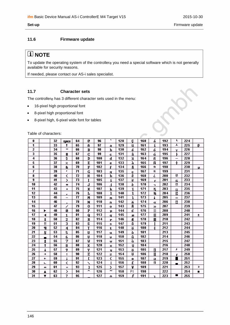
ifm Basic Device Manual AS-i ControllerE M4 Target V15 2015-10-30
Set-up Firmware update
146
11.6 Firmware update
NOTE
To update the operating system of the controllere you need a special software which is not generally
available for security reasons.
If needed, please contact our AS-i sales specialist.
11.7 Character sets
The controllere has 3 different character sets used in the menu:
16-pixel high proportional font
8-pixel high proportional font
8-pixel high, 6-pixel wide font for tables
Table of characters:
ifm Basic Device Manual AS-i ControllerE M4 Target V15 2015-10-30
Programming Deviations from the indications in the programming manual
147
12 Programming
In the supplementary manual "PLC programming with CoDeSys® 2.3" you will obtain more detailed information about the use of the programming system "CoDeSys for Automation Alliance". This manual can be downloaded free of charge from ifm's website at: → www.ifm.com > Select country/language > [Service] > [Download] > [Bus system AS-Interface]
12.1 Deviations from the indications in the programming manual
As opposed to the information in the programming manual, the following particularities apply to the controllere:
Retain variables are not automatically stored. To do so, the function block "Store_Retain" must be called.
Task management is not implemented.
Persistent variables are not implemented.
Target visualisation is not possible.
12.2 Online changes in the PLC
To reduce the data volume to be transmitted to the controllere, CoDeSys® only transmits the changed
POUs to the PLC. This accelerates programming in case of program changes during set-up. The term "Online Change" describes a function of the device allowing a change to the PLC program without interrupting the program. So the processing of the changed PLC program is possible without resetting the outputs.
WARNING
Dangerous, uncontrolled machine states!
The changeover to the changed PLC project can take up to 100 ms in case of "Online Change". During this time the outputs remain in their current state. The PLC data is not initialised after "Online Change".
► Stop the machine/system or bring it into a safe state before changing the PLC program in the controllere.
→ page 118, chapter How are the operating modes for the PLC selected?

ifm Basic Device Manual AS-i ControllerE M4 Target V15 2015-10-30
Programming Boot project / source code
148
12.3 Boot project / source code
The project loaded in the controllere is at first only stored in the volatile SRAM, just like the AS-i
configuration. This means it will be lost if the controllere is no longer supplied with 24 V.
Boot process: When the supply voltage of the controllere is switched on, the operating system copies the programs
and data stored as boot project to the SRAM where they are executed (boot process). After this, the AS-i masters receive their configuration data. The AS-i masters initialise the AS-i slaves and start the data transfer to the slaves.
12.3.1 Create boot project
WARNING
Dangerous, uncontrolled machine states!
The flash process can take 5 to 20 seconds when creating a boot project! During this time the outputs remain in their current state.
► Stop the machine/system or bring it into a safe state before creating a boot project or saving the AS-i configuration → page 118, chapter How are the operating modes for the PLC selected?
When the configuration of an AS-i system is finished and the PLC project tested, this information must be non-volatilely stored in the flash memory. This is done in CoDeSys® via [Online] > [Create boot project].
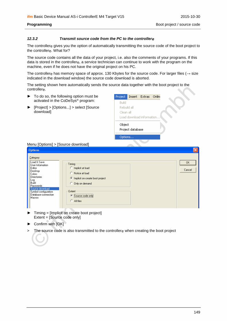
ifm Basic Device Manual AS-i ControllerE M4 Target V15 2015-10-30
Programming Boot project / source code
149
12.3.2 Transmit source code from the PC to the controllere
The controllere gives you the option of automatically transmitting the source code of the boot project to
the controllere. What for?
The source code contains all the data of your project, i.e. also the comments of your programs. If this data is stored in the controllere, a service technician can continue to work with the program on the
machine, even if he does not have the original project on his PC.
The controllere has memory space of approx. 130 Kbytes for the source code. For larger files (→ size
indicated in the download window) the source code download is aborted.
The setting shown here automatically sends the source data together with the boot project to the controllere.
► To do so, the following option must be activated in the CoDeSys® program:
► [Project] > [Options...] > select [Source download]
Menu [Options] > [Source download]
► Timing = [Implicit on create boot project] Extent = [Source code only]
► Confirm with [OK]
> The source code is also transmitted to the controllere when creating the boot project

ifm Basic Device Manual AS-i ControllerE M4 Target V15 2015-10-30
Programming Boot project / source code
150
12.3.3 Transmit source code from the controllere to the PC
Your project was transmitted as source code from the PC to the controllere and is available there. It is
now also possible to transmit the source code from the controllere to the PC.
To demonstrate this, save and close your current project.
► In CoDeSys® menu [File] > [Open…]
► Click on [PLC…]: [Open project from PLC]
► Click on the symbol [▼]
► Select the target suitable for the controllere used
► Confirm with [OK]
► In the "Online" menu select [Communication Parameters]
► Select the setting (→ CoDeSys® manual) which matches the setting in the controllere
► See for yourself that the project transmitted from the controllere corresponds to your original
project.
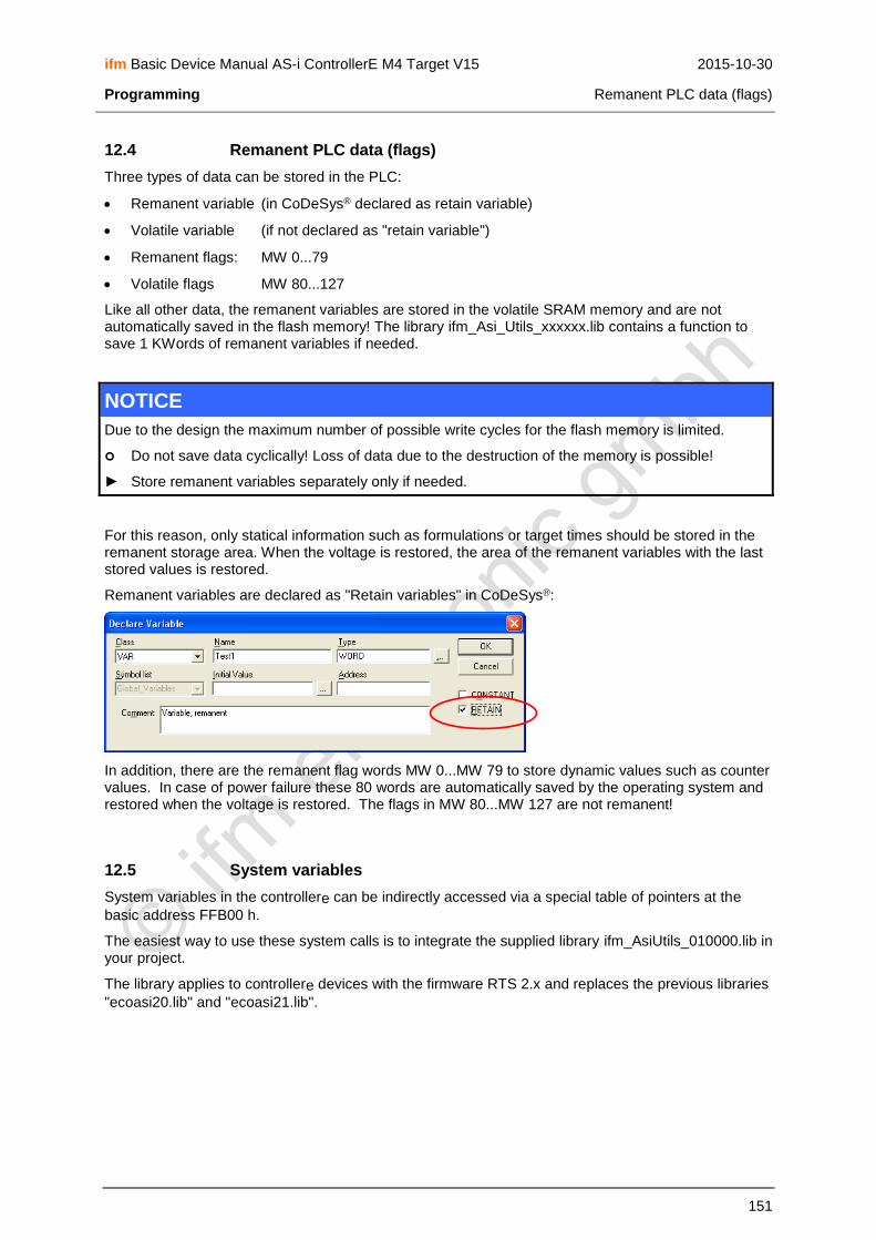
ifm Basic Device Manual AS-i ControllerE M4 Target V15 2015-10-30
Programming Remanent PLC data (flags)
151
12.4 Remanent PLC data (flags)
Three types of data can be stored in the PLC:
Remanent variable (in CoDeSys® declared as retain variable)
Volatile variable (if not declared as "retain variable")
Remanent flags: MW 0...79
Volatile flags MW 80...127
Like all other data, the remanent variables are stored in the volatile SRAM memory and are not automatically saved in the flash memory! The library ifm_Asi_Utils_xxxxxx.lib contains a function to save 1 KWords of remanent variables if needed.
NOTICE
Due to the design the maximum number of possible write cycles for the flash memory is limited.
Do not save data cyclically! Loss of data due to the destruction of the memory is possible!
► Store remanent variables separately only if needed.
For this reason, only statical information such as formulations or target times should be stored in the remanent storage area. When the voltage is restored, the area of the remanent variables with the last stored values is restored.
Remanent variables are declared as "Retain variables" in CoDeSys®:
In addition, there are the remanent flag words MW 0...MW 79 to store dynamic values such as counter values. In case of power failure these 80 words are automatically saved by the operating system and restored when the voltage is restored. The flags in MW 80...MW 127 are not remanent!
12.5 System variables
System variables in the controllere can be indirectly accessed via a special table of pointers at the
basic address FFB00 h.
The easiest way to use these system calls is to integrate the supplied library ifm_AsiUtils_010000.lib in your project.
The library applies to controllere devices with the firmware RTS 2.x and replaces the previous libraries
"ecoasi20.lib" and "ecoasi21.lib".

ifm Basic Device Manual AS-i ControllerE M4 Target V15 2015-10-30
Programming Overview PLC addresses
152
12.6 Overview PLC addresses
The PLC addesses (IEC addresses) consist of several elements in the indicated order:
Start character % The definition of an address starts with "%"
Data type
I Inputs (of sensors) are defined by an "I" for input
Q Outputs (of actuators) are defined by a "Q" for output
M Flags are defined by an "M"
Data length
X Bit information is defined by an "X"
B Bytes (= 8 bits) are defined by a "B"
W Words (= 2 bytes = 16 bits) are defined by a "W"
Identification (m) Indication of the AS-i master
Slave address (s) Indication of the slave address
12.6.1 Example pushbutton module
An AS-i pushbutton module AC2088 is connected to the master 1 as slave 6B. At which addresses are the pushbuttons and indicators accessible in the PLC program?
The data sheet specifies: AS-i profile = S-B.A.E
Assignment LED red LED green Pushbutton red
Pushbutton green
Data bit D0 D1 D2 D3
This results in the following addresses for the PLC program in the controllere:
AS-i
Pushbutton Indicator
green %IX11.6.3 %QX11.6.1
red %IX11.6.2 %QX11.6.0
The following pages will show examples of IEC addresses in the PLC of the controllere.

ifm Basic Device Manual AS-i ControllerE M4 Target V15 2015-10-30
Programming Overview PLC addresses
153
12.6.2 IEC addresses in the PLC of the controllere
For the digital slave inputs and outputs
% I B 1. 7
% Q X 12. 2 .3
Data area Type of access
Identification Slave address Data bit
I = input
Q = output
B = byte
X = bit
1 = S/A slave on master 1
2 = S/A slave on master 2
11 = B slave on master 1
12 = B slave on master 2
1 = slave 1
2 = slave 2
…
31 = slave 31
If type of access = X:
0 = D0 1 = D1 2 = D2 3 = D3
S/A slave = single slave or A slave
For the analogue slave inputs and outputs
% I W 21. 6 .0
% Q W 22. 9 .3
Data area Type of access
Identification Slave address Data channel
I = input
Q = output W = word
21 = master 1
22 = master 2
1 = slave 1
2 = slave 2
…
31 = slave 31
0 = 1st channel S/A slave
1 = 2nd channel S/A slave
2 = 3rd channel single slave or: 1st channel B slave
3 = 4th channel single slave or: 2nd channel B slave
4 = status
S/A slave = single slave or A slave A/B slaves have max. 2 analogue channels
Status information of analogue slaves
Word no.
Bit
15 14 13 12 11 10 9 8 7 6 5 4 3 2 1 0
0 analogue data channel 0 from/to slave 1 or: analogue data channel 0 from/to slave -A
1 analogue data channel 1 from/to slave 1 or: analogue data channel 1 from/to slave 1A
2 analogue data channel 2 from/to slave 1 or: analogue data channel 0 from/to slave 1B
3 analogue data channel 3 from/to slave 1 or: analogue data channel 1 from/to slave 1B
4 TIB TOB TIA TOA TVB OVB TVA OVA O3 V3 O2 V2 O1 V1 O0 V0
5 analogue data channel 0 from/to slave 2 or: analogue data channel 0 from/to slave 2A
6 analogue data channel 1 from/to slave 2 or: analogue data channel 1 from/to slave 2A
7 analogue data channel 2 from/to slave 2 or: analogue data channel 0 from/to slave 2B
8 analogue data channel 3 from/to slave 2 or: analogue data channel 1 from/to slave 2B
9 TIB TOB TIA TOA TVB OVB TVA OVA O3 V3 O2 V2 O1 V1 O0 V0

ifm Basic Device Manual AS-i ControllerE M4 Target V15 2015-10-30
Programming Overview PLC addresses
154
Word no.
Bit
15 14 13 12 11 10 9 8 7 6 5 4 3 2 1 0
… …
150 analogue data channel 0 from/to slave 31 or: analogue data channel 0 from/to slave 31A
151 analogue data channel 1 from/to slave 31 or: analogue data channel 1 from/to slave 31A
152 analogue data channel 2 from/to slave 31 or: analogue data channel 0 from/to slave 31B
153 analogue data channel 3 from/to slave 31 or: analogue data channel 1 from/to slave 31B
154 TIB TOB TIA TOA TVB OVB TVA OVA O3 V3 O2 V2 O1 V1 O0 V0
Legend:
Vn Validity bit "valid" for channel number n = 0...3
NOTE: set Vn = "1" for analogue output slaves!
On Bit "overflow" for channel number n = 0…3
OVA
Channel-independent bit "output data valid" of A slave
CTT1: 0 = more than 3.5 s have elapsed since the last update of the output values 1 = slave requests new output data within the next 3 s
CTT2…CTT5: 0 = slave receives no new output data 1 = slave receives new output data
TVA
Channel-independent bit "transmission valid" of A slave/single slave:
0 = error during transmission or: timeout 1 = transmission of analogue input/output data OK
OVB
Channel-independent bit "output data valid" of B slave:
CTT1: 0 = more than 3.5 s have elapsed since the last update of the output values 1 = slave requests new output data within the next 3 s
CTT2…CTT5: 0 = slave receives no new output data 1 = slave receives new output data
NOTE: only valid for analogue output slaves. Set OVB = 0 for input slaves!
TVB
Channel-independent bit "transmission valid" of B slave:
0 = error during transmission or: Timeout 1 = transmission of analogue input/output data OK
TIA Slave transmits analogue input data...
0 = in the analogue mode (15 bits, with sign) 1 = in the transparent mode (16 bits, without sign)
TIB
TOA slave receives analogue output data...
0 = in the analogue mode (15 bits, with sign) 1 = in the transparent mode (16 bits, without sign)
TOB

ifm Basic Device Manual AS-i ControllerE M4 Target V15 2015-10-30
Programming Overview PLC addresses
155
For flags
% M X 125 .0
% M B 164
% M W 82
% M D 41
Data area Type of access –– IEC address index Data bit
M = flag
X = bit
not used
words 0…79 = remanent words 80…127 = not remanent
0...15 bit access in the defined word address
16...2047* bit access to the words following the defined word address
B = byte bytes 0…159 = remanent bytes 160…255 = not remanent
–– W = word words 0…79 = remanent words 80…127 = not remanent
D = double word double words 0...39 = remanent double words 40...63 = not remanent
* Maximum data bit number for defined word address 0. If the defined word address is, for example, 126, the maximum data bit number is 31 (access to bit 15 of flag word 127) because otherwise the length of the flag area is exceeded.
Examples:
%MX17.16 = %MX18.0 %MX0.2047 = %MX127.15 %MX126.31 = %MX127.15
Relationship between double word, word and byte
MD0
remanent
MW1 MW0
MB3 MB2 MB1 MB0
MD1
MW3 MW2
MB7 MB6 MB5 MB4
…
MD39
MW79 MW78
MB159 MB158 MB157 MB156
MD40
not remanent
MW81 MW80
MB163 MB162 MB161 MB160
MD41
MW83 MW82
MB167 MB166 MB165 MB164
…
MD63
MW127 MW126
MB255 MB254 MB253 MB252

ifm Basic Device Manual AS-i ControllerE M4 Target V15 2015-10-30
Programming Overview PLC addresses
156
For configuration data (slaves 0…31B)
% I W 31. 8
Data area Type of access
Identification IEC address index ––
I = input W = word 31 = master 1
32 = master 2
0…63
96…159
current configuration
projected configuration not used
Current Configuration Data (CDI)
Word address for master 1: xx = 31 for master 2: xx = 32
Of slave Word address for master 1: xx = 31 for master 2: xx = 32
Of slave
%IWxx.0 0 %IWxx.32 *)
%IWxx.1 1(A) %IWxx.33 1B
%IWxx.2 2(A) %IWxx.34 2B
%IWxx.3 3(A) %IWxx.35 3B
%IWxx.4 4(A) %IWxx.36 4B
%IWxx.5 5(A) %IWxx.37 5B
%IWxx.6 6(A) %IWxx.38 6B
%IWxx.7 7(A) %IWxx.39 7B
%IWxx.8 8(A) %IWxx.40 8B
%IWxx.9 9(A) %IWxx.41 9B
%IWxx.10 10(A) %IWxx.42 10B
%IWxx.11 11(A) %IWxx.43 11B
%IWxx.12 12(A) %IWxx.44 12B
%IWxx.13 13(A) %IWxx.45 13B
%IWxx.14 14(A) %IWxx.46 14B
%IWxx.15 15(A) %IWxx.47 15B
%IWxx.16 16(A) %IWxx.48 16B
%IWxx.17 17(A) %IWxx.49 17B
%IWxx.18 18(A) %IWxx.50 18B
%IWxx.19 19(A) %IWxx.51 19B
%IWxx.20 20(A) %IWxx.52 20B
%IWxx.21 21(A) %IWxx.53 21B
%IWxx.22 22(A) %IWxx.54 22B
%IWxx.23 23(A) %IWxx.55 23B
%IWxx.24 24(A) %IWxx.56 24B
%IWxx.25 25(A) %IWxx.57 25B
%IWxx.26 26(A) %IWxx.58 26B
%IWxx.27 27(A) %IWxx.59 27B
%IWxx.28 28(A) %IWxx.60 28B
%IWxx.29 29(A) %IWxx.61 29B
%IWxx.30 30(A) %IWxx.62 30B

ifm Basic Device Manual AS-i ControllerE M4 Target V15 2015-10-30
Programming Overview PLC addresses
157
Word address for master 1: xx = 31 for master 2: xx = 32
Of slave Word address for master 1: xx = 31 for master 2: xx = 32
Of slave
%IWxx.31 31(A) %IWxx.63 31B
*) The address 0B is not possible, therefore these values are set to 0 by default.
Projected configuration data (CDI)
Word address for master 1: xx = 31 for master 2: xx = 32
Of slave Word address for master 1: xx = 31 for master 2: xx = 32
Of slave
%IWxx.96 0(A) %IWxx.128 *)
%IWxx.97 1(A) %IWxx.129 1B
%IWxx.98 2(A) %IWxx.130 2B
%IWxx.99 3(A) %IWxx.131 3B
%IWxx.100 4(A) %IWxx.132 4B
%IWxx.101 5(A) %IWxx.133 5B
%IWxx.102 6(A) %IWxx.134 6B
%IWxx.103 7(A) %IWxx.135 7B
%IWxx.104 8(A) %IWxx.136 8B
%IWxx.105 9(A) %IWxx.137 9B
%IWxx.106 10(A) %IWxx.138 10B
%IWxx.107 11(A) %IWxx.139 11B
%IWxx.108 12(A) %IWxx.140 12B
%IWxx.109 13(A) %IWxx.141 13B
%IWxx.110 14(A) %IWxx.142 14B
%IWxx.111 15(A) %IWxx.143 15B
%IWxx.112 16(A) %IWxx.144 16B
%IWxx.113 17(A) %IWxx.145 17B
%IWxx.114 18(A) %IWxx.146 18B
%IWxx.115 19(A) %IWxx.147 19B
%IWxx.116 20(A) %IWxx.148 20B
%IWxx.117 21(A) %IWxx.149 21B
%IWxx.118 22(A) %IWxx.150 22B
%IWxx.119 23(A) %IWxx.151 23B
%IWxx.120 24(A) %IWxx.152 24B
%IWxx.121 25(A) %IWxx.153 25B
%IWxx.122 26(A) %IWxx.154 26B
%IWxx.123 27(A) %IWxx.155 27B
%IWxx.124 28(A) %IWxx.156 28B
%IWxx.125 29(A) %IWxx.157 29B
%IWxx.126 30(A) %IWxx.158 30B
%IWxx.127 31(A) %IWxx.159 31B
*) The address 0B is not possible, therefore these values are set to 0 by default.

ifm Basic Device Manual AS-i ControllerE M4 Target V15 2015-10-30
Programming Overview PLC addresses
158
For parameter data (slaves 1(A)…31B)
% I W 31. 64
Data area Type of access
Identification IEC address index ––
I = input W = word 31 = master 1
32 = master 2
64….79
160…175
current parameters
reflected parameters not used
Current parameter data
Word address
for master 1: xx = 31 for master 2: xx = 32
Bits 12...15 Bits 8...11 Bits 4...7 Bits 0...3
Current parameter data of slave...
%IWxx.64 4(A) 3(A) 2(A) 1(A)
%IWxx.65 8(A) 7(A) 6(A) 5(A)
%IWxx.66 12(A) 11(A) 10(A) 9(A)
%IWxx.67 16(A) 15(A) 14(A) 13(A)
%IWxx.68 20(A) 19(A) 18(A) 17(A)
%IWxx.69 24(A) 23(A) 22(A) 21(A)
%IWxx.70 28(A) 27(A) 26(A) 25(A)
%IWxx.71 1B 31(A) 30(A) 29(A)
%IWxx.72 5B 4B 3B 2B
%IWxx.73 9B 8B 7B 6B
%IWxx.74 13B 12B 11B 10B
%IWxx.75 17B 16B 15B 14B
%IWxx.76 21B 20B 19B 18B
%IWxx.77 25B 24B 23B 22B
%IWxx.78 29B 28B 27B 26B
%IWxx.79 reserved 31 F 30 F
Reflected parameter data
Word address
for master 1: xx = 31 for master 2: xx = 32
Bits 12...15 Bits 8...11 Bits 4...7 Bits 0...3
Reflected parameters of slave...
%IWxx.160 4(A) 3(A) 2(A) 1(A)
%IWxx.161 8(A) 7(A) 6(A) 5(A)
%IWxx.162 12(A) 11(A) 10(A) 9(A)
%IWxx.163 16(A) 15(A) 14(A) 13(A)
%IWxx.164 20(A) 19(A) 18(A) 17(A)
%IWxx.165 24(A) 23(A) 22(A) 21(A)
%IWxx.166 28(A) 27(A) 26(A) 25(A)
%IWxx.167 1B 31(A) 30(A) 29(A)
%IWxx.168 5B 4B 3B 2B
%IWxx.169 9B 8B 7B 6B
%IWxx.170 13B 12B 11B 10B
%IWxx.171 17B 16B 15B 14B
%IWxx.172 21B 20B 19B 18B
%IWxx.173 25B 24B 23B 22B
%IWxx.174 29B 28B 27B 26B
%IWxx.175 reserved 31B 30B

ifm Basic Device Manual AS-i ControllerE M4 Target V15 2015-10-30
Programming Overview PLC addresses
159
Examples:
Reflected parameter data of slave 6B on master 2: → %IW32.169 (bits 0…3)
Current parameter for slave 6B on master 2: → %IW32.73 (bits 0…3)
For the slave list LAS (list of active slaves)
% I W 31. 80
Data area Type of access
Identification Slave selection ––
I = input W = word 31 = master 1
32 = master 2
80 = LAS of the slaves 1(A)…15(A)
81 = LAS of the slaves 16(A)…31(A)
82 = LAS of the slaves 1B…15B
83 = LAS of the slaves 16B…31B
not used
Details → page 160, chapter Slave lists
For the slave list LDS (list of detected slaves)
% I W 31. 84
Data area Type of access
Identification Slave selection ––
I = input W = word 31 = master 1
32 = master 2
84 = LDS of the slaves 1(A)…15(A)
85 = LDS of the slaves 16(A)…31(A)
86 = LDS of the slaves 1B…15B
87 = LDS of the slaves 16B…31B
not used
Details → page 160, chapter Slave lists
For the slave list LPF (list of slaves with periphery faults)
% I W 31. 88
Data area Type of access
Identification Slave selection ––
I = input W = word 31 = master 1
32 = master 2
88 = LPF of the slaves 1(A)…15(A)
89 = LPF of the slaves 16(A)…31(A)
90 = LPF of the slaves 1B…15B
91 = LPF of the slaves 16B…31B
not used
Details → page 160, chapter Slave lists

ifm Basic Device Manual AS-i ControllerE M4 Target V15 2015-10-30
Programming Overview PLC addresses
160
For the slave list LPS (list of projected slaves)
% I W 31. 92
Data area Type of access
Identification Slave selection ––
I = input W = word 31 = master 1
32 = master 2
92 = LPS of the slaves 1(A)…15(A)
93 = LPS of the slaves 16(A)…31(A)
94 = LPS of the slaves 1B…15B
95 = LPS of the slaves 16B…31B
not used
Details → page 160, chapter Slave lists
Slave lists
For the diagnosis of the AS-i system the controllere provides lists for every master:
LAS = list of active slaves LDS = list of detected slaves LPF = list of slaves with periphery fault LPS = list of projected slaves
Each of the different slaves lists is stored in four words (word no. 0...3).
In the following table you will find the addresses of the four words in which the corresponding slave lists are stored.
Word no. Word address
for master 1: xx = 31 for master 2: xx = 32
LAS LDS LPF LPS
0 %IWxx.80 %IWxx.84 %IWxx.88 %IWxx.92
1 %IWxx.81 %IWxx.85 %IWxx.89 %IWxx.93
2 %IWxx.82 %IWxx.86 %IWxx.90 %IWxx.94
3 %IWxx.83 %IWxx.87 %IWxx.91 %IWxx.95
The bit assignment of these words (i.e. to which bit the slave information is assigned) is shown below.
Bit 15 14 13 12 11 10 9 8 7 6 5 4 3 2 1 0
Word Slave
0 15 (A) 14 (A) 13 (A) 12 (A) 11 (A) 10 (A) 9 (A) 8 (A) 7 (A) 6 (A) 5 (A) 4 (A) 3 (A) 2 (A) 1 (A) 0 *)
1 31 (A) 30 (A) 29 (A) 28 (A) 27 (A) 26 (A) 25 (A) 24 (A) 23 (A) 22 (A) 21 (A) 20 (A) 19 (A) 18 (A) 17 (A) 16 (A)
2 15 B 14 B 13 B 12 B 11 B 10 B 9 B 8 B 7 B 6 B 5 B 4 B 3 B 2 B 1 B res
3 31 B 30 B 29 B 28 B 27 B 26 B 25 B 24 B 23 B 22 B 21 B 20 B 19 B 18 B 17 B 16 B
*) LAS and LPS have no slave 0, so these values are set to 0 by default!
Examples: Information about standard slave 16 is stored in word no. 1, bit no. 0. Information about slave 28B is stored in word no. 3, bit no. 12.

ifm Basic Device Manual AS-i ControllerE M4 Target V15 2015-10-30
Programming Overview PLC addresses
161
For the slave telegram error counters
% I W 31. 176
Data area Type of access
Identification IEC address index ––
I = input W = word 31 = master 1
32 = master 2 176…237 = error counters of the slaves 1(A)…31B not used
Slave telegram error counters
Word address
for master 1: xx = 31 for master 2: xx = 32
Error counter for slave
Word address
for master 1: xx = 31 for master 2: xx = 32
Error counter for slave
%IWxx.176 1(A) %IWxx.207 1B
%IWxx.177 2(A) %IWxx.208 2B
%IWxx.178 3(A) %IWxx.209 3B
%IWxx.179 4(A) %IWxx.210 4B
%IWxx.180 5(A) %IWxx.211 5B
%IWxx.181 6(A) %IWxx.212 6B
%IWxx.182 7(A) %IWxx.213 7B
%IWxx.183 8(A) %IWxx.214 8B
%IWxx.184 9(A) %IWxx.215 9B
%IWxx.185 10(A) %IWxx.216 10B
%IWxx.186 11(A) %IWxx.217 11B
%IWxx.187 12(A) %IWxx.218 12B
%IWxx.188 13(A) %IWxx.219 13B
%IWxx.189 14(A) %IWxx.220 14B
%IWxx.190 15(A) %IWxx.221 15B
%IWxx.191 16(A) %IWxx.222 16B
%IWxx.192 17(A) %IWxx.223 17B
%IWxx.193 18(A) %IWxx.224 18B
%IWxx.194 19(A) %IWxx.225 19B
%IWxx.195 20(A) %IWxx.226 20B
%IWxx.196 21(A) %IWxx.227 21B
%IWxx.197 22(A) %IWxx.228 22B
%IWxx.198 23(A) %IWxx.229 23B
%IWxx.199 24(A) %IWxx.230 24B
%IWxx.200 25(A) %IWxx.231 25B
%IWxx.201 26(A) %IWxx.2xx 26B
%IWxx.202 27(A) %IWxx.233 27B
%IWxx.203 28(A) %IWxx.234 28B
%IWxx.204 29(A) %Wxx.235 29B
%IWxx.205 30(A) %IWxx.236 30B
%IWxx.206 31(A) %IWxx.237 31B
Example: Error counter slave 7 on master 1: → %IW31.182

ifm Basic Device Manual AS-i ControllerE M4 Target V15 2015-10-30
Programming Overview PLC addresses
162
For the configuration error counter
% I W 31. 238
Data area Type of access
Identification IEC address index ––
I = input W = word 31 = master 1
32 = master 2 238 = configuration error counter not used
Configuration error counter
Word address Configuration error counter
%IW31.238 Master 1
%IW32.238 Master 2
For the AS-i cycle counter
% I W 31. 239
Data area Type of access
Identification IEC address index ––
I = input W = word 31 = master 1
32 = master 2 239 = AS-i cycle counter not used
AS-i cycle counter
Word address AS-i error counter
%IW31.239 Master 1
%IW32.239 Master 2

ifm Basic Device Manual AS-i ControllerE M4 Target V15 2015-10-30
Programming Overview PLC addresses
163
For the master flags
% I W 31. 240
% I X 32. 241 .8
Data area Type of access
Identification Word selection Data bit no.
I = input W = word
X = bit
31 = master 1
32 = master 2
240 = master flags word 1
241 = master flags word 2
If type of access = X:
0…15
Word address
for master 1: xx = 31 for master 2: xx = 32
Bits Bit = TRUE means:
%IWxx.240 0
"No slave reset"
When executing the function "Config all" (via the menu or command channel of the controllere) the slaves are NOT reset as described in the AS-i specificaiton.
1...15 Reserved
%IWxx.241
0
"Config OK"
There is no configuration error. The configuration of all AS-i slaves in the network complies with the projection data.
1 "LDS.0"
One slave with the AS-i address 0 was detected on the master.
2 Reserved
3 Reserved
4 "Configuration_Active"
The controllere is in the configuration mode
5 "Normal_Operation_Active"
The AS-i master is in normal operation: it communicates with at least one slave.
6 "AS-i_Power_Fail"
AS-i voltage is too low
7 Reserved
8 "Periphery_OK"
None of the active AS-i slaves signals a periphery fault
9 "Auto_Address_Enable"
The mode "automatic addressing of the slaves" is activated on this master.
10...15 Reserved
Examples: To read the bit LDS.0 "slave 0 detected" for master 1, the address %IX31.241.1 is used; for master 2 the address %IX32.241.1 is used.

ifm Basic Device Manual AS-i ControllerE M4 Target V15 2015-10-30
Programming Overview PLC addresses
164
For the fieldbus data from/to the PLC of the controllere
% I W 0. 10
% I W 0. 20
Data area Type of access
Identification IEC address index ––
I = input
Q = output W = word 0 (fixed value) 0...63 = word x of the data field not used
NOTE: Only applies to devices with fieldbus interface. The Ethernet programming interface is NOT considered as a fieldbus interface.
For the extended data from/to the PLC of the controllere
% I W 4. 100
% I W 4. 27
Data area Type of access
Identification IEC address index ––
I = input
Q = output W = word 4 (fixed value) 0…255 = word x of the data field not used

ifm Basic Device Manual AS-i ControllerE M4 Target V15 2015-10-30
Programming Overview PLC addresses
165
12.6.3 Examples for addressing
Slave Selection Parameters Address examples
Binary single or A slave
All 4 bits in one byte
Output byte of slave 22 on master 1 %QB1.22
Input byte of slave 6A on master 2 %IB2.6
Individual bit Bit 3 (input) of slave 24 on master 2 %IX2.24.3
Bit 0 (output) of slave 8 on master 1 %QX1.8.0
Binary B slaves
All 4 bits in one byte
Output byte of slave 22B on master 1 %QB11.22
Input byte of slave 6B on master 2 %IB12.6
Individual bit Bit 3 (input) of slave 24B on master 2 %IX12.24.3
Bit 0 (output) of slave 8B on master 1 %QX11.8.0
Analogue slaves
All 16 bits in one channel (word)
Analogue input in 3rd channel of slave 31 on master 1
%IW21.31.2
Analogue input in 1st channel of slave 31A on master 1
%IW21.31.0
Analogue input in 1st channel of slave 31B on master 1
%IW21.31.2
Analogue output from 4th channel of slave 17 on master 2
%QW22.17.3
Analogue output from 2nd channel of slave 17B on master 2
%QW22.17.3
Status (channel 5)
→ table page 153
Status of slave 31(A) on master 2 %IW22.31.4
Status of slave 31B on master 2 %IW22.31.4
Flags
Complete flag wod
Flag word 21 (remanent) %MW21
Individual byte
Flag byte 162 (not remanent) %MB162
Individual bit Bit 8 from flag word 21 (remanent) %MX21.8

ifm Basic Device Manual AS-i ControllerE M4 Target V15 2015-10-30
Programming Overview PLC addresses
166
12.6.4 Further examples
Data Master Slave Address examples
Current parameter data (bits 0...3) → page 158 2 6B %IW32.73
Reflected parameter data (bits 0...3) → page 158 2 6B %IW32.169
Slave error counter → page 161 1 7 %IW31.182
2 6B %IW32.212
Configuration error counter → page 162 1 -- %IW31.238
AS-i cycle counter → page 162 2 -- %IW32.239
NOTE
All addresses in these further examples can only be read as WORD addresses. A breakdown into individual bits is only possible by copying the word to a symbolic address and retrieving this address bit by bit.
Example:
copy %IW31.81 to LASMaster1
copy %IW32.83 to LPSMaster2
Query: master 1, slave 16 / 16A in the list of active slaves
output to LASSlave16M1
Query: master 2, slave 22B in the list of projected slaves
output to LPSSlave22BM2
NOTE
A flag word consists of two flag bytes.
Flag word %MW(n) corresponds to the flag bytes %MB(2n) and %MB(2n+1). → page 155, table Relationship between double word, word and byte
Example: Flag word %MW21 corresponds to the flag bytes %MB42 and %MB43.

ifm Basic Device Manual AS-i ControllerE M4 Target V15 2015-10-30
Programming Access digital slave inputs/outputs via PLC
167
12.7 Access digital slave inputs/outputs via PLC
Digital slave I/Os can be accessed in 3 ways.
12.7.1 Access via addresses
Description → page 152, chapter Overview PLC addresses
12.7.2 Access via function calls
Description of the circuits of the function blocks → library ifm_Asi_Utils_xxxxxx.lib
Examples:
read slave inputs as byte
set slave outputs as byte
read slave outputs as byte

ifm Basic Device Manual AS-i ControllerE M4 Target V15 2015-10-30
Programming Access digital slave inputs/outputs via PLC
168
12.7.3 Indexed data access via the table of pointers
Using pointers you can have direct access to the stored information.
Example:
For detailed information → supplementary manual "PLC programming withCoDeSys® 2.3"

ifm Basic Device Manual AS-i ControllerE M4 Target V15 2015-10-30
Programming Read and write slave parameters via PLC
169
12.8 Read and write slave parameters via PLC
NOTE
Access to slave parameters is not trivial. Therefore always use the function calls in the library ifm_Asi_Utils_xxxxxx.lib.
Examples:
Changes the parameter in the slave "sl" on master "mstr"
After the change of a parameter the parameter list for the master "mstr" must be updated in the controllere.
Reads the current parameter value from slave "sl" and provides the value as "curPar"
Writes the value "wpp" as projected parameter for slave "sl" in the parameter list of the controllere
Reads the projected parameter for slave "sl" from the parameter list in the controllere and provides the value as "ppa"

ifm Basic Device Manual AS-i ControllerE M4 Target V15 2015-10-30
Programming Read in AS-i slave lists via PLC
170
12.9 Read in AS-i slave lists via PLC
Using the function calls from the library ifm_Asi_Utils_xxxxxx.lib the slave lists can be readas shown below.
Examples:
a) Access via function blocks
Query whether a slave with the address "sl" is active on the bus of master "mstr". If so:
> las = TRUE
Query whether a slave with the address "sl" is detected on the bus of master "mstr". If so:
> lds = TRUE
Query whether a slave with the address "sl" is projected on the bus of master "mstr". If so:
> lps = TRUE
Query whether there is a periphery fault on the slave with the address "sl". If so:
> lpf = TRUE
b) Access with pointers
For detailed information → supplementary manual "PLC programming with CoDeSys® 2.3"

ifm Basic Device Manual AS-i ControllerE M4 Target V15 2015-10-30
Programming Configure AS-i slaves via PLC
171
12.10 Configure AS-i slaves via PLC
The library ifm_Asi_Utils_xxxxxx.lib also contains function calls to reconfigure the AS-i system…
to revise the configuration table
to re-address slaves
to check the configuration
etc.
Examples:
Function block: All slaves detected on master "mstr" are entered as projected in the LPS of the controllere.
Program: reads the projected configuration of all A or single slaves on AS-i master "mstr"
Program: reads the current configuration of all A or single slaves on AS-i master "mstr"
Program: copies the current I/O configuration of the slave "sl" on master "mstr" to the variable "io"
Requirement: first call the function block Get_ASi_Config
Program: copies the current ID code of the slave "sl" on master "mstr" to the variable "id"
Requirement: first activate the function block Get_ASi_Config
Note on the network 0007 / 0008: If the parameter "B_Slaves" is " True ", the corresponding statement applies to the "configuration of all B slaves".

ifm Basic Device Manual AS-i ControllerE M4 Target V15 2015-10-30
Programming Overview system blocks
172
12.11 Overview system blocks
In addition to the CoDeSys® standard libraries, another system library for the controllere is on the CD:
ifm_Asi_Utils_xxxxxx.lib contains the blocks necessary for working with AS-i slaves version 2.x. In new projects the blocks of this library should be used for access to AS-i system information.
12.11.1 ifm_Asi_Utils_xxxxxx.lib blocks
Changing the slave address from "oldAddress" to "newAddress" as soon as "Start" changes to TRUE
Execution of an AS-i command
(possible commands → description "command channel" in separate fieldbus manual)
Reading the current configuration information of a connected AS-i slave
Reading the current input values of an AS-i slave
Reading the current output values of an AS-i slave
Reading which key of the controllere is actuated
Reading the configuration error counter
Reading the current parameters of an AS-i slave
Updating the global slave lists
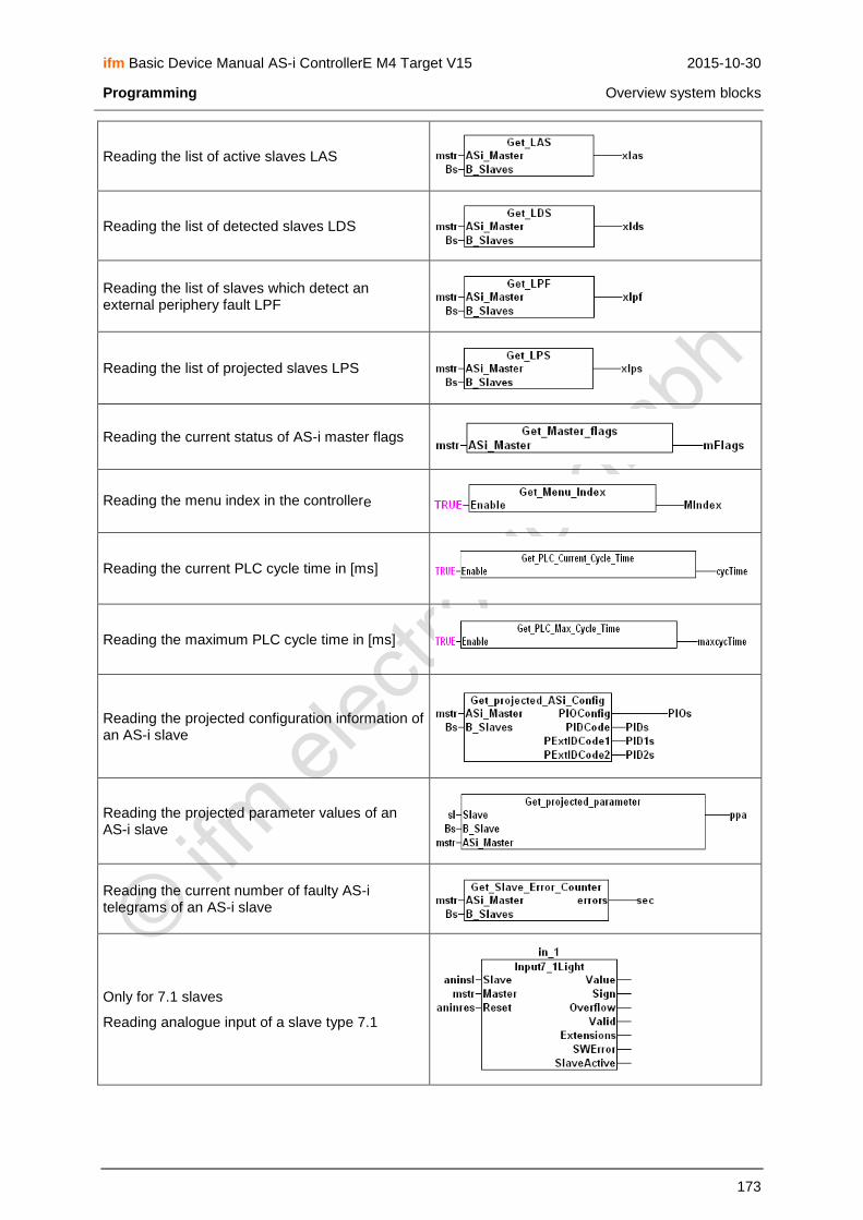
ifm Basic Device Manual AS-i ControllerE M4 Target V15 2015-10-30
Programming Overview system blocks
173
Reading the list of active slaves LAS
Reading the list of detected slaves LDS
Reading the list of slaves which detect an external periphery fault LPF
Reading the list of projected slaves LPS
Reading the current status of AS-i master flags
Reading the menu index in the controllere
Reading the current PLC cycle time in [ms]
Reading the maximum PLC cycle time in [ms]
Reading the projected configuration information of an AS-i slave
Reading the projected parameter values of an AS-i slave
Reading the current number of faulty AS-i telegrams of an AS-i slave
Only for 7.1 slaves
Reading analogue input of a slave type 7.1

ifm Basic Device Manual AS-i ControllerE M4 Target V15 2015-10-30
Programming Overview system blocks
174
Multiplex reading and writing of 8 bits of a slave
Transmit 2 data bits and 2 address bits per cycle in 4 cycles
Only for 7.1 slaves
Writing analogue output of a slave type 7.1
If the slave detects an external periphery fault, the output is TRUE
Updating AS-i configuration on an AS-i master as soon as "Start" changes to TRUE
Requires library I71Light.lib
Reading analogue inputs of a PT100 slave type 7.1
After changing one or several parameters of AS-i slaves, the set of parameters must be updated by a positive edge on "Start"
Called by the function block "Input7_1Light"
Organises the communication with the analogue inputs of slaves type 7.1
Setting the outputs of a slave to the contents of "value"
Setting the current parameters of a slave as soon as "Start" changes to TRUE

ifm Basic Device Manual AS-i ControllerE M4 Target V15 2015-10-30
Programming Overview system blocks
175
Selection of the operating mode of an AS-i master
1 = configuration mode
0 = protected mode
Setting the projected parameters of an AS-i slave
The output is TRUE if the slave is activated
The output is TRUE if the slave is detected
The output is TRUE if the slave is projected
Stores the variables defined as VAR_RETAIN in the flash memory
IMPORTANT: Due to the limited possible write accesses to the flash memory this command must not be carried out cyclically!
More details → software description

ifm Basic Device Manual AS-i ControllerE M4 Target V15 2015-10-30
Operation Selection of the PLC operating mode
176
13 Operation
In this chapter you will learn what you can do with the controllere during operation.
13.1 Selection of the PLC operating mode
→ page 118, chapter Which operating modes are available for the PLC in the controllere?
→ page 119, chapter How are the operating modes for the PLC selected?
13.2 Information about the stored PLC program
The controllere shows the data of the currently stored PLC program:
NOTE
Password level 1 required → page 142, chapter Password setting
[MENU] > [PLC Setup] > [PLC Info]
1.
► Press the key [MENU] MMEENNUU 0 UUSSEERR
2. Quick Setup
PLC Setup
Slave Lists
► Press [▼] to scroll to [PLC Setup] OOKK 1
▲ ▼ EESSCC

ifm Basic Device Manual AS-i ControllerE M4 Target V15 2015-10-30
Operation Information about the stored PLC program
177
3. Quick Setup
PLC Setup
Slave Lists
► Select [PLC Setup] with [OK] OOKK 1
▲ ▼ EESSCC
4. PPLLCC SSeettuupp
PLC Settings
PLC Info
► Press [▼] to scroll to [PLC Info] OOKK 42
▲ ▼ EESSCC
5. PPLLCC SSeettuupp
PLC Settings
PLC Info
► Select [PLC Info] with [OK] OOKK 42
▲ ▼ EESSCC
6. PPrroojjeecctt IInnffoo
Name: ASi_Test Version: Datum: 2006-06-02 13:16:26 Author: Adam Smith
> Name = file name of the PLC program
> Version = PLC program version, if stored in the project
> Date = date + time when the project was stored on the PC
> Author = name stored as author in the project
► Press [ESC] three times to return to the start screen
> That's it!
94 EESSCC

ifm Basic Device Manual AS-i ControllerE M4 Target V15 2015-10-30
Operation Display of detected slaves (list)
178
13.3 Display of detected slaves (list)
Indication at which slave address the controllere detected a slave (or several slaves) type A, B or S
(standard) on the bus irrespective of whether the slave is active on the bus.
Definition: A slave is considered to be detected by an AS-i master if the slave is activated and has sent the master its identifier.
[MENU] > [Slave Lists] > select master > [Detected Slaves]
1.
► Press the key [MENU] MMEENNUU 0 UUSSEERR
2. Quick Setup
PLC Setup
Slave Lists
► Press [▼] to scroll to [Slave Lists] OOKK 1
▲ ▼ EESSCC
3. Quick Setup
PLC Setup
Slave Lists
► Select [Slave Lists] with [OK] OOKK 1
▲ ▼ EESSCC
4. SSllaavvee LLiisstt ooff
AS-i Master 1
AS-i Master 2
► If necessary, press [▼] to scroll to AS-i master 2 OOKK 2
▲ ▼ EESSCC

ifm Basic Device Manual AS-i ControllerE M4 Target V15 2015-10-30
Operation Display of detected slaves (list)
179
5. SSllaavvee LLiisstt ooff
AS-i Master 1
AS-i Master 2
► Select requested AS-i master with [OK] OOKK 2
▲ ▼ EESSCC
6. Detect. Sl. ASi1
Project. Sl. ASi1
Active. Sl. ASi1
► Select [Detect. Sl.] with [OK] OOKK 91
▲ ▼ EESSCC
7. Detect. Sl. ASi1
0 1 2 3 4 5 A . . . . . . B . . . . . . S . . . . . .
> A table of detected slaves is displayed. Here: no slaves were detected on master 1 with the addresses 0 to 5.
► If necessary, press [▲] to scroll to the next address block
3
▲ ▼ EESSCC
8. Detect. Sl. ASi1
6 7 8 9 10 11 A ● - . - . . B - - . - . . S - ● . ● . .
> A table of detected slaves is displayed. In this example:
An A/B slave was detected as A slave at address 6, a single slave was detected at the addresses 7 and 9.
► Note found slave addresses
► If necessary, press [▲] to scroll to the next address block
► Press [ESC] four times to return to the start screen
> That's it!
3
▲ ▼ EESSCC

ifm Basic Device Manual AS-i ControllerE M4 Target V15 2015-10-30
Operation Display of projected slaves (list)
180
13.4 Display of projected slaves (list)
Indication at which slave address one (or several) slaves type A, B or S (standard) are projected on the bus.
Definition: A slave is considered to be projected on an AS-i master if the slave is entered in the "list of projected slaves" (LPS) in the controllere. To be entered in the LPS, the slave must be activated at
this time and have a valid, unique address.
[MENU] > [Slave Lists] > select master > [Project. Sl.]
1.
► Press the key [MENU] MMEENNUU 0 UUSSEERR
2. Quick Setup
PLC Setup
Slave Lists
► Press [▼] to scroll to [Slave Lists] OOKK 1
▲ ▼ EESSCC
3. Quick Setup
PLC Setup
Slave Lists
► Select [Slave Lists] with [OK] OOKK 1
▲ ▼ EESSCC
4. SSllaavvee LLiisstt ooff
AS-i Master 1
AS-i Master 2
► If necessary, press [▼] to scroll to AS-i master 2 OOKK 2
▲ ▼ EESSCC

ifm Basic Device Manual AS-i ControllerE M4 Target V15 2015-10-30
Operation Display of projected slaves (list)
181
5. SSllaavvee SSeettuupp ooff
AS-i Master 1
AS-i Master 2
► Select requested AS-i master with [OK] OOKK 2
▲ ▼ EESSCC
6. Detect. Sl. ASi1
Project. Sl. ASi1
Active. Sl. ASi1
► Press [▼] to scroll to [Project. Sl.] OOKK 91
▲ ▼ EESSCC
7. Detect. Sl. ASi1
Project. Sl. ASi1
Activ. Sl. ASi1
► Select [Project. Sl.] with [OK] OOKK 91
▲ ▼ EESSCC
8. Project. Sl. ASi1
0 1 2 3 4 5 A . . . . . . B . . . . . . S . . . . . .
> A table of projected slaves is displayed. Here: No slaves were projected on master 1 with the addresses 0 to 5.
► If necessary, press [▲] to scroll to the next address block
4
▲ ▼ EESSCC

ifm Basic Device Manual AS-i ControllerE M4 Target V15 2015-10-30
Operation Display of projected slaves (list)
182
9. Project. Sl. ASi1
6 7 8 9 10 11 A ● - . - . . B - - . - . . S - ● . ● . .
> A table of projected slaves is displayed. In this example:
An A/B slave was projected as A slave at the address 6,
a single slave was projected at the addresses 7 and 9.
► Note found slave addresses
► If necessary, press [▲] to scroll to the next address block
► Press [ESC] four times to return to the start screen
> That's it!
4
▲ ▼ EESSCC

ifm Basic Device Manual AS-i ControllerE M4 Target V15 2015-10-30
Operation Display of active slaves (list)
183
13.5 Display of active slaves (list)
Indication at which slave address the controllere detected an active slave type A, B or S (standard) on
the bus.
Definition: A slave is considered to be active on an AS-i master if the AS-i master cyclically exchanges data with the slave.
[MENU] > [Slave Lists] > select master > [Activated Slaves]
1.
► Press the key [MENU] MMEENNUU 0 UUSSEERR
2. Quick Setup
PLC Setup
Slave Lists
► Press [▼] to scroll to [Slave Lists] OOKK 1
▲ ▼ EESSCC
3. Quick Setup
PLC Setup
Slave Lists
► Select [Slave Lists] with [OK] OOKK 1
▲ ▼ EESSCC
4. SSllaavvee LLiisstt ooff
AS-i Master 1
AS-i Master 2
► If necessary, press [▼] to scroll to AS-i master 2 OOKK 2
▲ ▼ EESSCC

ifm Basic Device Manual AS-i ControllerE M4 Target V15 2015-10-30
Operation Display of active slaves (list)
184
5. SSllaavvee SSeettuupp ooff
AS-i Master 1
AS-i Master 2
► Select requested AS-i master with [OK] OOKK 2
▲ ▼ EESSCC
6. Detect. Sl. ASi1
Project. Sl. ASi1
Activ. Sl. ASi1
► Press [▼] to scroll to [Activ. Sl.] OOKK 91
▲ ▼ EESSCC
7. Detect. Sl. ASi1
Project. Sl. ASi1
Activ. Sl. ASi1
► Select [Activ. Sl.] with [OK] OOKK 91
▲ ▼ EESSCC
8. Active. Sl. ASi1
0 1 2 3 4 5 A . . . . . . B . . . . . . S . . . . . .
> A table of activated slaves is displayed. Here: no slaves were detected on master 1 with the addresses 0 to 5.
► If necessary, press [▲] to scroll to the next address block
5
▲ ▼ EESSCC

ifm Basic Device Manual AS-i ControllerE M4 Target V15 2015-10-30
Operation Display of active slaves (list)
185
9. Active. Sl. ASi1
6 7 8 9 10 11 A ● - . - . . B - - . - . . S - ● . ● . .
> A table of activated slaves is displayed. In this example:
An A/B slave was detected as active A slave at address 6,
an active single slave was detected at the addresses 7 and 9.
► Note found slave addresses
► If necessary, press [▲] to scroll to the next address block
► Press [ESC] four times to return to the start screen
> That's it!
5
▲ ▼ EESSCC
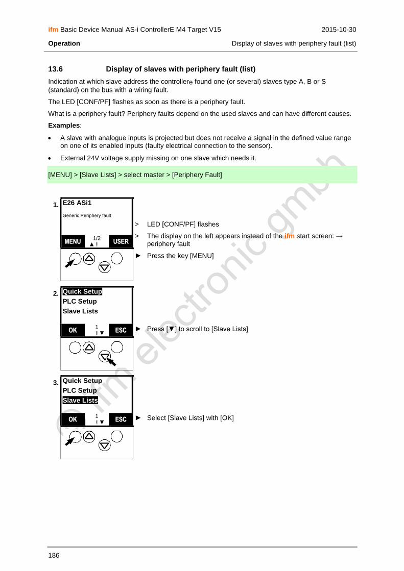
ifm Basic Device Manual AS-i ControllerE M4 Target V15 2015-10-30
Operation Display of slaves with periphery fault (list)
186
13.6 Display of slaves with periphery fault (list)
Indication at which slave address the controllere found one (or several) slaves type A, B or S
(standard) on the bus with a wiring fault.
The LED [CONF/PF] flashes as soon as there is a periphery fault.
What is a periphery fault? Periphery faults depend on the used slaves and can have different causes.
Examples:
A slave with analogue inputs is projected but does not receive a signal in the defined value range on one of its enabled inputs (faulty electrical connection to the sensor).
External 24V voltage supply missing on one slave which needs it.
[MENU] > [Slave Lists] > select master > [Periphery Fault]
1. E26 ASi1
Generic Periphery fault
> LED [CONF/PF] flashes
> The display on the left appears instead of the ifm start screen: → periphery fault
► Press the key [MENU]
MMEENNUU 1/2
▲ ! ▼ UUSSEERR
2. Quick Setup
PLC Setup
Slave Lists
► Press [▼] to scroll to [Slave Lists] OOKK 1
▲ ! ▼ EESSCC
3. Quick Setup
PLC Setup
Slave Lists
► Select [Slave Lists] with [OK] OOKK 1
▲ ! ▼ EESSCC

ifm Basic Device Manual AS-i ControllerE M4 Target V15 2015-10-30
Operation Display of slaves with periphery fault (list)
187
4. SSllaavvee LLiisstt ooff
AS-i Master 1
AS-i Master 2
► If necessary, press [▼] to scroll to AS-i master 2 OOKK 2
▲ ! ▼ EESSCC
5. SSllaavvee SSeettuupp ooff
AS-i Master 1
AS-i Master 2
► Select requested AS-i master with [OK] OOKK 2
▲ ! ▼ EESSCC
6. Detect. Sl. ASi1
Project. Sl. ASi1
Active. Sl. ASi1
► Press [▼] to scroll to [Periph. Flt.] OOKK 91
▲ ! ▼ EESSCC
7. Project. Sl. ASi1
Active. Sl. ASi1
Periph. Flt. ASi1
► Select [Periph. Flt.] with [OK] OOKK 91
▲ ! ▼ EESSCC

ifm Basic Device Manual AS-i ControllerE M4 Target V15 2015-10-30
Operation Display of slaves with periphery fault (list)
188
8. Periph. Flt. ASi1
0 1 2 3 4 5 A . . . . . . B . . . . . . S . . . . . .
> A table of the slaves with periphery fault is displayed.
Here: No slaves with periphery fault were detected on master 1 with the addresses 0 to 5.
► If necessary, press [▲] to scroll to the next address block
6
▲ ! ▼ EESSCC
9. Periph. Flt. ASi1
18 19 20 21 22 23 A . . - . . . B . . - . . . S . . ● . . .
> A table of the slaves with periphery fault is displayed.
Here: A single slave with periphery fault was detected at address 20
► Note found slave addresses
► If necessary, press [▲] to scroll to the next address block
► Press [ESC] four times to return to the start screen
> That's it!
6
▲ ! ▼ EESSCC

ifm Basic Device Manual AS-i ControllerE M4 Target V15 2015-10-30
Operation Display of slave with periphery fault
189
13.7 Display of slave with periphery fault
Indication at which slave address the controllere found a slave type A, B or S (standard) on the bus
with a wiring fault (periphery).
→ page 186, chapter Display of slaves with periphery fault (list)
1. E26 ASi1
Generic Periphery fault
> LED [CONF/PF] flashes
> The display on the left appears instead of the ifm start screen: Periphery fault on AS-i master 1:
► Press [▲] to scroll to [Slave Lists]
MMEENNUU 1/2
▲ ! ▼ UUSSEERR
2. E13 ASi1 Slv.20
Periphery fault detected
> LED [CONF/PF] flashes
> Slave 20 on AS-i master 1 signals periphery fault
► Press [▼] to return to the start screen
MMEENNUU 2/2
▲ ! ▼ UUSSEERR

ifm Basic Device Manual AS-i ControllerE M4 Target V15 2015-10-30
Operation Detection of an unknown slave address
190
13.8 Detection of an unknown slave address
If the address of a connected slave is not known, you can easily find out the slave address:
1.
> The LED [PROJ] is out.
► If the LED [PROJ] lights, change the master to "protected mode". → page 116, chapter How are the operating modes for the AS-i master selected?
► Remove the unknown slave from the bus.
MMEENNUU 0 UUSSEERR
2. E25 ASi1
Config. Error
> The display on the left appears instead of the ifm start screen: "Configuration error"
> LED [CONF/PF] lights
Cause: Slaves which the controllere has in its projection list cannot be
found on the bus.
Note: error description → page 239, chapter Error description
► Press [▲] to scroll to the error screen
MMEENNUU 1/2
▲ ! ▼ UUSSEERR
3. E25 ASi1 Slv.7
Slave not present
> Display of error message: "AS-i master 1: slave 7 not present" In this example: The unknown slave has the address 7.
► Connect the removed slave again
MMEENNUU 2/2
▲ ! ▼ UUSSEERR
4.
> That's it: The ifm start screen is displayed again MMEENNUU 0 UUSSEERR

ifm Basic Device Manual AS-i ControllerE M4 Target V15 2015-10-30
Operation Number of AS-i voltage failures on the AS-i master
191
13.9 Number of AS-i voltage failures on the AS-i master
How often was an inadmissible decrease or interruption of the voltage supply of the AS-i bus responsible for system failures? The controllere shows it:
Here you cannot see in detail when which fault occurred. → page 239, chapter Error description
The error counter is reset...
when the device is switched off and on again
with the function "Reset error counter", → page 200
[MENU] > [Diagnostics] > select master > [Voltage Disturbance]
1.
► Press the key [MENU] MMEENNUU 0 UUSSEERR
2. Quick Setup
PLC Setup
Slave Lists
► Press [▼] to scroll to [Diagnostics] OOKK 1
▲ ▼ EESSCC
3. Slave Lists
Address Slave
Diagnostics
► Select [Diagnostics] with [OK] OOKK 1
▲ ▼ EESSCC

ifm Basic Device Manual AS-i ControllerE M4 Target V15 2015-10-30
Operation Number of AS-i voltage failures on the AS-i master
192
4. DDiiaaggnnoossttiiccss ooff
AS-i Master 1
Safety Master 1
► If necessary, press [▼] to scroll to another master OOKK 130
▲ ▼ EESSCC
5. DDiiaaggnnoossttiiccss ooff
AS-i Master 1
Safety Master 1
► Select requested master with [OK] OOKK 130
▲ ▼ EESSCC
6. AASS--ii 11 ddiiaaggnnoosstt..
Voltage Disturb.
Config. Error
► Select [Voltage Disturb.] with [OK] OOKK 131
▲ ▼ EESSCC
7. AASS--ii 11
PPoowweerr FFaaiill CCttrr..
22 > Display of the number of failures of the AS-i supply on the master
Reset error counter: → page 200
► Press [ESC] four times to return to the start screen
133
EESSCC
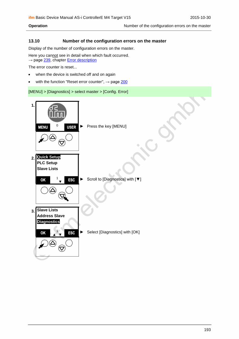
ifm Basic Device Manual AS-i ControllerE M4 Target V15 2015-10-30
Operation Number of the configuration errors on the master
193
13.10 Number of the configuration errors on the master
Display of the number of configuration errors on the master.
Here you cannot see in detail when which fault occurred. → page 239, chapter Error description
The error counter is reset...
when the device is switched off and on again
with the function "Reset error counter", → page 200
[MENU] > [Diagnostics] > select master > [Config. Error]
1.
► Press the key [MENU] MMEENNUU 0 UUSSEERR
2. Quick Setup
PLC Setup
Slave Lists
► Scroll to [Diagnostics] with [▼] OOKK 1
▲ ▼ EESSCC
3. Slave Lists
Address Slave
Diagnostics
► Select [Diagnostics] with [OK] OOKK 1
▲ ▼ EESSCC

ifm Basic Device Manual AS-i ControllerE M4 Target V15 2015-10-30
Operation Number of the configuration errors on the master
194
4. DDiiaaggnnoossttiiccss ooff
AS-i Master 1
Safety Master 1
► If necessary, press [▼] to scroll to another master OOKK 130
▲ ▼ EESSCC
5. DDiiaaggnnoossttiiccss ooff
AS-i Master 1
Safety Master 1
► Select requested master with [OK] OOKK 130
▲ ▼ EESSCC
6. AASS--ii 11 ddiiaaggnnoosstt..
Voltage Disturb.
Config. Error
► Press [▼] to select [Config. Error] OOKK 131
▲ ▼ EESSCC
7. AASS--ii 11 ddiiaaggnnoosstt..
Voltage Disturb.
Config. Error
► Select [Config. Error] with [OK] OOKK 131
▲ ▼ EESSCC
8. AASS--ii MMaasstteerr 11
CCoonnffiigg EErrrroorr CCoouunntt..
2244
> Display of the number of configuration errors on the master
Reset error counter: → page 200
► Press [ESC] four times to return to the start screen
50 EESSCC

ifm Basic Device Manual AS-i ControllerE M4 Target V15 2015-10-30
Operation AS-i telegram errors on the master
195
13.11 AS-i telegram errors on the master
A telegram error means that the expected response telegram from a slave is not received within a defined time or that the signal sequences in the response telegram cannot be interpreted by the AS-i master.
Examples:
The AS-i line is asymmetrically operated due to an electrical fault (earth fault on one side). In this case the AS-i signal can no longer be clearly detected.
The electrical AS-i connection to an AS-i slave is not ok.
Interference by the electric environment of the AS-i network (EMC) affects the AS-i telegram traffic.
Here you cannot see in detail when which fault occurred. → page 239, chapter Error description
The error counter is reset...
when the device is switched off and on again
with the function Reset error counter, → page 200
[MENU] > [Diagnostics] > select master > [Telegram Error]
1.
► Press the key [MENU] MMEENNUU 0 UUSSEERR
2. Quick Setup
PLC Setup
Slave Lists
► Press [▼] to scroll to [Diagnostics] OOKK 1
▲ ▼ EESSCC
3. Slave Lists
Address Slave
Diagnostics
► Select [Diagnostics] with [OK] OOKK 1
▲ ▼ EESSCC
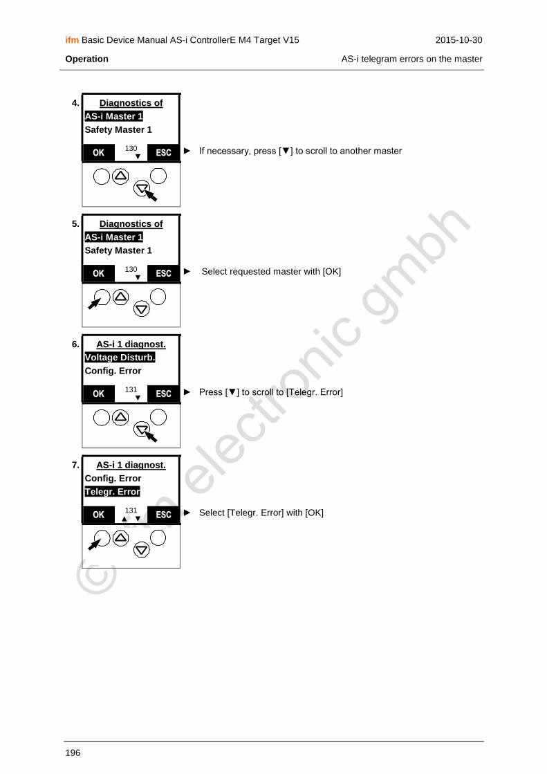
ifm Basic Device Manual AS-i ControllerE M4 Target V15 2015-10-30
Operation AS-i telegram errors on the master
196
4. DDiiaaggnnoossttiiccss ooff
AS-i Master 1
Safety Master 1
► If necessary, press [▼] to scroll to another master OOKK 130
▲ ▼ EESSCC
5. DDiiaaggnnoossttiiccss ooff
AS-i Master 1
Safety Master 1
► Select requested master with [OK] OOKK 130
▲ ▼ EESSCC
6. AASS--ii 11 ddiiaaggnnoosstt..
Voltage Disturb.
Config. Error
► Press [▼] to scroll to [Telegr. Error] OOKK 131
▲ ▼ EESSCC
7. AASS--ii 11 ddiiaaggnnoosstt..
Config. Error
Telegr. Error
► Select [Telegr. Error] with [OK] OOKK 131
▲ ▼ EESSCC

ifm Basic Device Manual AS-i ControllerE M4 Target V15 2015-10-30
Operation AS-i telegram errors on the master
197
8. AASS--ii MMaasstteerr 11
TTeelleeggrr.. EErrrroorr CCoouunntt..
00..44 %%
48 / s
> Dynamic display of AS-i telegram errors in per cent of the transmitted telegrams
> Dynamic display of AS-i telegram errors per second
► Scroll to the next screen with [MORE]
MMOORREE 51 EESSCC
9. AASS--ii MMaasstteerr 11
PPeerrffoorrmmaannccee
4 slave(s) active 1328 cycles / [s]
> Dynamic display of the performance of this master:
Number of active slaves
Number of AS-i cycles per second
► Press [ESC] four times to return to the start screen
95 EESSCC

ifm Basic Device Manual AS-i ControllerE M4 Target V15 2015-10-30
Operation Number of disturbed telegrams on the master (from noisy slaves)
198
13.12 Number of disturbed telegrams on the master (from noisy slaves)
You want to know how many disturbed telegramsthe different slaves have transmitted (since the last [Reset Error Count.])? The controllere shows it, sorted by the number of disturbed telegrams.
Here you cannot see in detail when which error occurred. → page 239, chapter Error description
The error counter is reset...
when the device is switched off and on again
with the function Reset error counter, → page 200
[MENU] > [Diagnostics] > select master > [Noisy Slaves]
1.
► Press the key [MENU] MMEENNUU 0 UUSSEERR
2. Quick Setup
PLC Setup
Slave Lists
► Press [▼] to scroll to [Diagnostics] OOKK 1
▲ ▼ EESSCC
3. Slave Lists
Address Slave
Diagnostics
► Select [Diagnostics] with [OK] OOKK 1
▲ ▼ EESSCC
4. DDiiaaggnnoossttiiccss ooff
AS-i Master 1
Safety Master 1
► If necessary, press [▼] to scroll to another master OOKK 130
▲ ▼ EESSCC

ifm Basic Device Manual AS-i ControllerE M4 Target V15 2015-10-30
Operation Number of disturbed telegrams on the master (from noisy slaves)
199
5. DDiiaaggnnoossttiiccss ooff
AS-i Master 1
Safety Master 1
► Select requested master with [OK] OOKK 130
▲ ▼ EESSCC
6. AASS--ii 11 ddiiaaggnnoosstt..
Voltage Disturb.
Config. Error
► Press [▼] to scroll to [Noisy Slaves] OOKK 131
▲ ▼ EESSCC
7. AASS--ii 11 ddiiaaggnnoosstt..
Telegr. Error
Noisy Slaves
► Select [Noisy Slaves] with [OK] OOKK 131
▲ ▼ EESSCC
8. AASS--ii 11 NNooiissyy SSllvv..
IX Slv. Tele. 1 7 122 2 6A 83
> Dynamic display of the number of disturbed telegrams of the different slaves, sorted by frequency of occurrence:
Column "IX": Number of rank order (frequency)
Column "Slv.": Address of the slave
Column "Tele.": Number of disturbed telegrams
► Sort again by current rank order with [SORT]
► Press [▲] or [▼] to scroll to the slaves with higher or lower rank order
As an alternative:
► Press [ESC] four times to return to the start screen
SSOORRTT 134
▲ ▼ EESSCC

ifm Basic Device Manual AS-i ControllerE M4 Target V15 2015-10-30
Operation Reset error counter
200
13.13 Reset error counter
Here you learn how to reset the error counters in the diagnostic memory of the controllere .
NOTE
You should reset the diagnostic memory of the controllere only after the analysis of the values stored
so far.
The reset process cannot be reversed.
Password level 1 required → page 142, chapter Password setting
[MENU] > [Diagnostics] > select master > [Reset Error Counter] > [OK]
1.
► Press the key [MENU] MMEENNUU 0 UUSSEERR
2. Quick Setup
PLC Setup
Slave Lists
► Press [▼] to scroll to [Diagnostics] OOKK 1
▲ ▼ EESSCC
3. Slave Lists
Address Slave
Diagnostics
► Select [Diagnostics] with [OK] OOKK 1
▲ ▼ EESSCC

ifm Basic Device Manual AS-i ControllerE M4 Target V15 2015-10-30
Operation Reset error counter
201
4. DDiiaaggnnoossttiiccss ooff
AS-i Master 1
Safety Master 1
► If necessary, press [▼] to scroll to another master OOKK 130
▲ ▼ EESSCC
5. DDiiaaggnnoossttiiccss ooff
AS-i Master 1
Safety Master 1
► Select requested master with [OK] OOKK 130
▲ ▼ EESSCC
6. AASS--ii 11 ddiiaaggnnoosstt..
Voltage Disturb.
Config. Error
► Press [▼] to scroll to [Reset Error Count.] OOKK 131
▲ ▼ EESSCC
7. AASS--ii 11 ddiiaaggnnoosstt..
Noisy Slaves
Reset Error Count.
► Select [Reset Error Count.] with [OK] OOKK 131
▲ ▼ EESSCC
8. AASS--ii 11 MMaasstteerr 11
RReesseett EErrrroorr CCoouunntt..?? > Safety query:
"Reset Error Count.?"
► Reset all error counters with [OK]
> Return to screen 131
As an alternative:
► Scroll to screen 131 with [ESC] without changing the error counters
OOKK 52 EESSCC

ifm Basic Device Manual AS-i ControllerE M4 Target V15 2015-10-30
Operation Display of the longest cycle time
202
13.14 Display of the longest cycle time
Display of the longest cycle time of the system in [ms] since the last reset or after the last power on of the device:
[MENU] > [Diagnostics] > select master > [Cycle time]
1.
► Press the key [MENU] MMEENNUU 0 UUSSEERR
2. Quick Setup
PLC Setup
Slave Lists
► Press [▼] to scroll to [Diagnostics] OOKK 1
▲ ▼ EESSCC
3. Slave Lists
Address Slave
Diagnostics
► Select [Diagnostics] with [OK] OOKK 1
▲ ▼ EESSCC
4. DDiiaaggnnoossttiiccss ooff
AS-i Master 1
Safety Master 1
► If necessary, press [▼] to scroll to another master OOKK 130
▲ ▼ EESSCC

ifm Basic Device Manual AS-i ControllerE M4 Target V15 2015-10-30
Operation Display of the longest cycle time
203
5. DDiiaaggnnoossttiiccss ooff
AS-i Master 1
Safety Master 1
► Select requested master with [OK] OOKK 130
▲ ▼ EESSCC
6. AASS--ii 11 ddiiaaggnnoosstt..
Voltage Disturb.
Config. Error
► Press [▼] to scroll to [Cycle time] OOKK 131
▲ ▼ EESSCC
7. AASS--ii 11 ddiiaaggnnoosstt..
Reset Error Count.
Cycle time
► Select [Cycle time] with [OK] OOKK 131
▲ ▼ EESSCC
8. SSyysstteemm rreeaaccttiioonn
[[mmss]]:: 116622
> Display of the longest cycle time of the AS-i system in [ms] since the last reset
► To update the display open the screen again: Keys [ESC] > [OK] > [OK]
> Value increases or remains unchanged
► Set cycle time measurement series to 0 with [CLEAR]
CCLLEEAARR 137
EESSCC
9. SSyysstteemm rreeaaccttiioonn
[[mmss]]:: 22 > Reset of the previous measurement series
> Start of the new measurement series
► Press [ESC] three times to return to the start screen
CCLLEEAARR 137
EESSCC

ifm Basic Device Manual AS-i ControllerE M4 Target V15 2015-10-30
Operation Read states of the safety monitor
204
13.15 Read states of the safety monitor
Using the following method the controllere shows you the current data of the AS-i safety monitor.
[MENU] > [Diagnostics] > select safety master > [Read Monitor]
1.
► Press the key [MENU] MMEENNUU 0 UUSSEERR
2. Quick Setup
PLC Setup
Slave Lists
► Press [▼] to scroll to [Diagnostics] OOKK 1
▲ ▼ EESSCC
3. Slave Lists
Address Slave
Diagnostics
► Select [Diagnostics] with [OK] OOKK 1
▲ ▼ EESSCC
4. DDiiaaggnnoossttiiccss ooff
AS-i Master 1
Safety Master 1
► Press [▼] to scroll to requested safety master OOKK 130
▲ ▼ EESSCC

ifm Basic Device Manual AS-i ControllerE M4 Target V15 2015-10-30
Operation Read states of the safety monitor
205
5. DDiiaaggnnoossttiiccss ooff
AS-i Master 1
Safety Master 1
► Select requested master with [OK] OOKK 130
▲ ▼ EESSCC
6. SSaaffeettyy MMoonniittoorr
Read Monitor
Trigg.Slave
► Select [Read Monitor] with [OK] OOKK 141
▲ ▼ EESSCC
a) No safety device triggered
7. RReeaadd MMoonniittoorr
Slave 31 OSSD1: green OSSD2: green Config. Mode: active
> Display of the current data of the safety monitor:
Slave = configured AS-i slave address
OSSD1 = LED colour* for enable circuit 1
OSSD2 = LED colour* for enable circuit 2
Configuration mode active / not active = operating mode of the safety monitor
► Scroll to more data with [MORE]
OR:
► Return to screen 141 with [ESC]
MMOORREE 142
▲ ▼ EESSCC
* red = relay contact interrupted: a safety device has triggered
yellow = relay contact interrupted + restart disable = ready to start
green = relay contact closed: safety devices ok
NOTE
Depending on the connected safety devices (one / two channels) the displays of OSSD1 and OSSD2 may be different.

ifm Basic Device Manual AS-i ControllerE M4 Target V15 2015-10-30
Operation Read states of the safety monitor
206
b) Safety device triggered
7. RReeaadd MMoonniittoorr
Slave 31 OSSD1: red OSSD2: red Config. Mode: active
> Display of the current data of the safety monitor:
Slave = configured AS-i slave address
OSSD1 = LED colour* for enable circuit 1 Here: enable circuit interrupted
OSSD2 = LED colour* for enable circuit 2 Here: enable circuit interrupted
Configuration mode active / not active = operating mode of the safety monitor (not active = Run mode)
► Scroll to more data with [MORE] (only possible in case of an error)
OR:
► Return to screen 141 with [ESC]
MMOORREE 142
▲ ! ▼ EESSCC
8. OOSSSSDD11 SSllaavvee 3311
Device Index 32 [1/3] Colour: red
> Display of the data of enable circuit 1:
Slave = configured AS-i slave address
Device index (according to the configuration of the safety monitor with the software "ASIMON")
[1/3] = display of the first of 3 sub-indexes Sub-index 1 = sensor Sub-index 2 = start condition Sub-index 3 = relay contact
LED colour* for enable circuit 1
Press [▲] or [▼] to scroll between the status messages of the other concerned index devices
► Scroll to enable circuit 2 with [OSSD2]
OR:
► Return to screen 141 with [ESC]
OOSSSSDD22 143
▲ ! ▼ EESSCC
9. OOSSSSDD22 SSllaavvee 3311
Device Index 32 [1/3] Colour: red
Like screen 143, but for OSSD2
► Scroll to enable circuit 1 with [OSSD1]
OR:
► Return to screen 141 with [ESC]
OOSSSSDD11 144
▲ ! ▼ EESSCC
* red = relay contact interrupted: a safety device triggered
yellow = relay contact interrupted + restart disable = ready to start
green = relay contact closed: safety devices ok
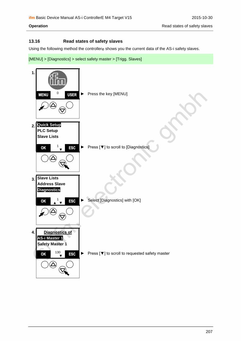
ifm Basic Device Manual AS-i ControllerE M4 Target V15 2015-10-30
Operation Read states of safety slaves
207
13.16 Read states of safety slaves
Using the following method the controllere shows you the current data of the AS-i safety slaves.
[MENU] > [Diagnostics] > select safety master > [Trigg. Slaves]
1.
► Press the key [MENU] MMEENNUU 0 UUSSEERR
2. Quick Setup
PLC Setup
Slave Lists
► Press [▼] to scroll to [Diagnostics] OOKK 1
▲ ▼ EESSCC
3. Slave Lists
Address Slave
Diagnostics
► Select [Diagnostics] with [OK] OOKK 1
▲ ▼ EESSCC
4. DDiiaaggnnoossttiiccss ooff
AS-i Master 1
Safety Master 1
► Press [▼] to scroll to requested safety master OOKK 130
▲ ▼ EESSCC

ifm Basic Device Manual AS-i ControllerE M4 Target V15 2015-10-30
Operation Read states of safety slaves
208
5. DDiiaaggnnoossttiiccss ooff
AS-i Master 1
Safety Master 1
► Select requested master with [OK] OOKK 130
▲ ▼ EESSCC
6. SSaaffeettyy MMoonniittoorr
Read Monitor
Trigg.Slave
► Press [▼] to scroll to [Trigg.Slave] OOKK 141
▲ ▼ EESSCC
7. SSaaffeettyy MMoonniittoorr
Read Monitor
Trigg.Slave
► Select [Trigg.Slave] with [OK] OOKK 141
▲ ▼ EESSCC
a) Safety sensor not actuated / not triggered
8. TTrriigggg.. SSllaavveess
Address: - - - - Event:
> Display of the current data of the first detected and triggered safety slave
Here: no sensor triggered No further displays / functions
► Return to screen 141 with [ESC]
RREESSEETT 145
▲ ▼ EESSCC
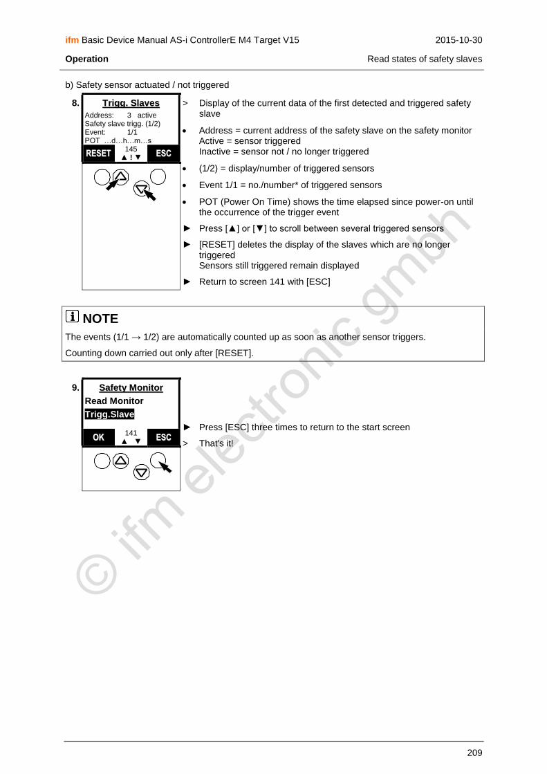
ifm Basic Device Manual AS-i ControllerE M4 Target V15 2015-10-30
Operation Read states of safety slaves
209
b) Safety sensor actuated / not triggered
8. TTrriigggg.. SSllaavveess
Address: 3 active Safety slave trigg. (1/2) Event: 1/1 POT …d…h…m…s
> Display of the current data of the first detected and triggered safety slave
Address = current address of the safety slave on the safety monitor Active = sensor triggered Inactive = sensor not / no longer triggered
(1/2) = display/number of triggered sensors
Event 1/1 = no./number* of triggered sensors
POT (Power On Time) shows the time elapsed since power-on until the occurrence of the trigger event
► Press [▲] or [▼] to scroll between several triggered sensors
► [RESET] deletes the display of the slaves which are no longer triggered Sensors still triggered remain displayed
► Return to screen 141 with [ESC]
RREESSEETT 145
▲ ! ▼ EESSCC
NOTE
The events (1/1 → 1/2) are automatically counted up as soon as another sensor triggers.
Counting down carried out only after [RESET].
9. SSaaffeettyy MMoonniittoorr
Read Monitor
Trigg.Slave
► Press [ESC] three times to return to the start screen
> That's it! OOKK
141 ▲ ▼ EESSCC

ifm Basic Device Manual AS-i ControllerE M4 Target V15 2015-10-30
Operation Set AS-i address(es) of the safety monitor(s)
210
13.17 Set AS-i address(es) of the safety monitor(s)
Using the following method you set the same AS-i address for the safety monitor in the controllere that
you have already stored in the safety monitor with the "ASIMON" safety parameter setting software.
Therefore the controllere can now exchange data with the safety monitor via a special protocol.
More information on the protocol → device manual of the safety monitor.
WARNING
The protocol changes output states of the slaves set via the protocol.
Danger for people and machine by uncontrolled machine states.
► Only set AS-i safety monitors in this menu.
[MENU] > [Diagnostics] > select safety master > [Enable Monitor]
1.
► Press the key [MENU] MMEENNUU 0 UUSSEERR
2. Quick Setup
PLC Setup
Slave Lists
► Press [▼] to scroll to [Diagnostics] OOKK 1
▲ ▼ EESSCC
3. Slave Lists
Address Slave
Diagnostics
► Select [Diagnostics] with [OK] OOKK 1
▲ ▼ EESSCC

ifm Basic Device Manual AS-i ControllerE M4 Target V15 2015-10-30
Operation Set AS-i address(es) of the safety monitor(s)
211
4. DDiiaaggnnoossttiiccss ooff
AS-i Master 1
Safety Master 1
► Press [▼] to scroll to requested safety master OOKK 130
▲ ▼ EESSCC
5. DDiiaaggnnoossttiiccss ooff
AS-i Master 1
Safety Master 1
► Select requested master with [OK] OOKK 130
▲ ▼ EESSCC
6. SSaaffeettyy MMoonniittoorr
Read Monitor
Trigg.Slave
► Press [▼] to scroll to [Enable Monitor] OOKK 141
▲ ▼ EESSCC
7. SSaaffeettyy MMoonniittoorr
Trigg.Slave
Enable Monitor
► Select [Enable Monitor] with [OK] OOKK 141
▲ ▼ EESSCC
8. EEnnaabbllee MMoonniittoorr
Address: 31 > Display safety note
► Acknowledge with [OK]
> Display of the address of the first found safety monitor
► Press [▲] or [▼] to scroll to the requested safety monitor IMPORTANT: Select the same setting as with "ASIMON" in the safety monitor
OOKK 146
▲ ▼ EESSCC

ifm Basic Device Manual AS-i ControllerE M4 Target V15 2015-10-30
Operation Set AS-i address(es) of the safety monitor(s)
212
9. EEnnaabbllee MMoonniittoorr
Address: 30
► Confirm the requested address of the safety monitor with [OK] OOKK 146
▲ ▼ EESSCC
10. EEnnaabbllee MMoonniittoorr
SSllaavvee aaddddrreessss
aallrreeaaddyy iinn LLPPMM
> Message that the selected address was found in the list of projected monitors (LPM)
> Controllere enters the AS-i address of the safety monitor in its list of
participants
> Therefore the controllere can now exchange data with the safety
monitor via a special protocol.
► Return to screen 141 with [ESC]
OOKK 146
▲ ▼ EESSCC
11. SSaaffeettyy MMoonniittoorr
Trigg.Slave
Enable Monitor
► Press [ESC] three times to return to the start screen
> That's it! OOKK
141 ▲ ▼ EESSCC

ifm Basic Device Manual AS-i ControllerE M4 Target V15 2015-10-30
Operation Reset the AS-i address(es) of the safety monitor(s)
213
13.18 Reset the AS-i address(es) of the safety monitor(s)
With the following method you delete the AS-i address of the safety monitor in the controllere.
IMPORTANT:
Therefore the controllere processes the safety monitor just like an ordinary slave (4I/4O) - without
taking safety-related data into account.
[MENU] > [Diagnostics] > select safety master > [Disable Monitor]
1.
► Press the key [MENU] MMEENNUU 0 UUSSEERR
2. Quick Setup
PLC Setup
Slave Lists
► Press [▼] to scroll to [Diagnostics] OOKK 1
▲ ▼ EESSCC
3. Slave Lists
Address Slave
Diagnostics
► Select [Diagnostics] with [OK] OOKK 1
▲ ▼ EESSCC
4. DDiiaaggnnoossttiiccss ooff
AS-i Master 1
Safety Master 1
► Press [▼] to scroll to requested safety master OOKK 130
▲ ▼ EESSCC

ifm Basic Device Manual AS-i ControllerE M4 Target V15 2015-10-30
Operation Reset the AS-i address(es) of the safety monitor(s)
214
5. DDiiaaggnnoossttiiccss ooff
AS-i Master 1
Safety Master 1
► Select requested master with [OK] OOKK 130
▲ ▼ EESSCC
6. SSaaffeettyy MMoonniittoorr
Read Monitor
Trigg.Slave
► Press [▼] to scroll to [Disable Monitor] OOKK 141
▲ ▼ EESSCC
7. SSaaffeettyy MMoonniittoorr
Enable Monitor
Disable Monitor
► Select [Disable Monitor] with [OK] OOKK 141
▲ ▼ EESSCC
8. DDiissaabbllee MMoonniittoorr
Address: 31
> Display of the address of the first found safety monitor
► Press [▲] or [▼] to scroll to the requested address of the safety monitor
OOKK 147
▲ ▼ EESSCC
9. DDiissaabbllee MMoonniittoorr
Address: 31
► Confirm the requested address of the safety monitor with [OK]
► Confirm safety query with [ OK] OOKK
147 ▲ ▼ EESSCC

ifm Basic Device Manual AS-i ControllerE M4 Target V15 2015-10-30
Operation Reset the AS-i address(es) of the safety monitor(s)
215
10. SSaaffeettyy MMoonniittoorr
Enable Monitor
Disable Monitor > The controllere deletes the AS-i address from its list of participants
> Therefore the controllere processes the safety monitor just like an
ordinary slave - without taking safety-related data into account.
► Press [ESC] three times to return to the start screen
> That's it!
OOKK 141
▲ ▼ EESSCC

ifm Basic Device Manual AS-i ControllerE M4 Target V15 2015-10-30
Operation Set the diagnostic characteristics of the safety monitor
216
13.19 Set the diagnostic characteristics of the safety monitor
With the following method you set in the controllere how the safety monitor was configured with
"ASIMON".
[MENU] > [Diagnostics] > select safety master > [Setup Monitor]
1.
► Press the key [MENU] MMEENNUU 0 UUSSEERR
2. Quick Setup
PLC Setup
Slave Lists
► Press [▼] to scroll to [Diagnostics] OOKK 1
▲ ▼ EESSCC
3. Slave Lists
Address Slave
Diagnostics
► Select [Diagnostics] with [OK] OOKK 1
▲ ▼ EESSCC
4. DDiiaaggnnoossttiiccss ooff
AS-i Master 1
Safety Master 1
► Press [▼] to scroll to requested safety master OOKK 130
▲ ▼ EESSCC

ifm Basic Device Manual AS-i ControllerE M4 Target V15 2015-10-30
Operation Set the diagnostic characteristics of the safety monitor
217
5. DDiiaaggnnoossttiiccss ooff
AS-i Master 1
Safety Master 1
► Select requested master with [OK] OOKK 130
▲ ▼ EESSCC
6. SSaaffeettyy MMoonniittoorr
Read Monitor
Trigg.Slave
► Press [▼] to scroll to [Setup Monitor] OOKK 141
▲ ▼ EESSCC
7. SSaaffeettyy MMoonniittoorr
Disable Monitor
Setup Monitor
► Select [Setup Monitor] with [OK] OOKK 141
▲ ▼ EESSCC
8. MMoonniittoorr SSeettttiinnggss
Sorted diag.
Unsorted diag.
> Display of the current setting of the safety monitor (marked line = active):
Sorted = sorting by enable circuits
Unsorted = sorting by numbers of the safety devices
► Press [▲] or [▼] to scroll to the requested setting IMPORTANT: Select the same setting as selected for the safety monitor via "ASIMON"
OOKK 159
▲ ▼ EESSCC
9. MMoonniittoorr SSeettttiinnggss
Sorted diag.
Unsorted diag.
► Confirm setting with [OK] OOKK 159
▲ ▼ EESSCC

ifm Basic Device Manual AS-i ControllerE M4 Target V15 2015-10-30
Operation Set the diagnostic characteristics of the safety monitor
218
10. SSaaffeettyy MMoonniittoorr
Disable Monitor
Setup Monitor
► Press [ESC] three times to return to the start screen
> That's it! OOKK
141 ▲ ▼ EESSCC

ifm Basic Device Manual AS-i ControllerE M4 Target V15 2015-10-30
Operation Reset diagnostic states of safety devices
219
13.20 Reset diagnostic states of safety devices
Using the following method you delete the stored diagnostic states of the safety devices.
NOTE
Password level 1 required → page 142, chapter Password setting
[MENU] > [Diagnostics] > select safety master > [Reset all] > [OK]
1.
► Press the key [MENU] MMEENNUU 0 UUSSEERR
2. Quick Setup
PLC Setup
Slave Lists
► Press [▼] to scroll to [Diagnostics] OOKK 1
▲ ▼ EESSCC
3. Slave Lists
Address Slave
Diagnostics
► Select [Diagnostics] with [OK] OOKK 1
▲ ▼ EESSCC
4. DDiiaaggnnoossttiiccss ooff
AS-i Master 1
Safety Master 1
► Press [▼] to scroll to requested safety master OOKK 130
▲ ▼ EESSCC

ifm Basic Device Manual AS-i ControllerE M4 Target V15 2015-10-30
Operation Reset diagnostic states of safety devices
220
5. DDiiaaggnnoossttiiccss ooff
AS-i Master 1
Safety Master 1
► Select requested master with [OK] OOKK 130
▲ ▼ EESSCC
6. SSaaffeettyy MMoonniittoorr
Read Monitor
Trigg.Slave
► Press [▼] to scroll to [Reset all] OOKK 141
▲ ▼ EESSCC
7. SSaaffeettyy MMoonniittoorr
Setup Monitor
Reset all
► Select [Reset all] with [OK]
► Confirm safety query with [ OK] OOKK
141 ▲ ▼ EESSCC
8. DDiiaaggnnoossttiiccss ooff
AS-i Master 1
Safety Master 1 > The controllere deletes the entries in the event list
► Press [ESC] twice to return to the start screen
> That's it!
OOKK 130
▲ ▼ EESSCC

ifm Basic Device Manual AS-i ControllerE M4 Target V15 2015-10-30
Operation Change operating mode of the AS-i master
221
13.21 Change operating mode of the AS-i master
Please refer to the following chapters in the manual:
→ page 115, chapter Which operating modes are available for the AS-i master?
→ page 116, chapter How are the operating modes for the AS-i master selected?

ifm Basic Device Manual AS-i ControllerE M4 Target V15 2015-10-30
Operation Display of slave data
222
13.22 Display of slave data
You want to know how the individual slaves are configured?This is how to see it:
[MENU] > [Slave info] > select master
1.
► Press the key [MENU] MMEENNUU 0 UUSSEERR
2. Quick Setup
PLC Setup
Slave Lists
► Press [▼] to scroll to [Slave Info] OOKK 1
▲ ▼ EESSCC
3. Master Setup
Fieldbus Setup
Slave info
► Select [Slave info] with [OK] OOKK 1
▲ ▼ EESSCC
4. SSllaavvee iinnffoo ooff
AS-i Master 1
AS-i Master 2
► If necessary, press [▼] to scroll to master 2 OOKK 62
▲ ▼ EESSCC

ifm Basic Device Manual AS-i ControllerE M4 Target V15 2015-10-30
Operation Display of slave data
223
5. SSllaavvee iinnffoo ooff
AS-i Master 1
AS-i Master 2
► Select requested master with [OK] OOKK 62
▲ ▼ EESSCC
6. AASS--ii MMaasstteerr 11
SSeelleecctt SSllaavvee
66AA > Display of the lowest found valid slave address
► If necessary, press [▲] or [▼] to scroll to another slave address which is active on the master
OOKK 63
▲ ▼ EESSCC
7. AASS--ii 11 SSllaavvee 66AA
Input: 0001 [ 01h ] Output: 0011 [ 03h ]
> Dynamic display of the digital inputs and outputs as binary value and hex value:
Input: digital inputs
Output: digital outputs
► Press [▲] or [▼] to scroll to any other slave address
> Display of values of the other slave address. If the address is not assigned to an active slave: display of values as "0000 [00h]"
► Scroll to the next screen with [MORE]
As an alternative:
► Return to screen 62 with [ESC]
MMOORREE 64
▲ ▼ EESSCC
8. AASS--ii 11 SSllaavvee 2200
Analogue CH1 IN +312 Analogue CH2 IN +120 Analogue CH3 IN +10 Analogue CH4 IN +75
> Dynamic display of the analogue (input) channels as decimal values:
If the slave has no analogue channel: Display of the value as ". . . . . .“
If no CTT slave: - analogue inputs: "IN" in front of the value - analogue outputs: "OUT" in front of the value
► Press [▲] or [▼] to scroll to any other slave address
► Scroll to the next screen with [MORE]
As an alternative:
► Return to screen 62 with [ESC]
MMOORREE 65
▲ ▼ EESSCC

ifm Basic Device Manual AS-i ControllerE M4 Target V15 2015-10-30
Operation Display of slave data
224
9. AASS--ii 11 SSllaavvee 22BB
Analogue CH1 OUT +312 Analogue CH2 OUT +120 Analogue CH3 OUT +10 Analogue CH4 OUT +75
Figure only for CTT slaves
> Dynamic display of the analogue output channels as decimal values:
If the slave has no analogue channel: Display of the value as ". . . . . .“
► Press [▲] or [▼] to scroll to any other slave address
► Scroll to the next screen with [MORE]
As an alternative:
► Return to screen 62 with [ESC]
MMOORREE 163
▲ ▼ EESSCC
10. AASS--ii 11 SSllaavvee 1188AA
Slave in transparent mode CTT transfer valid CTT output valid Overf.: 0000 Valid: 0000
Figure only for CTT slaves
> Dynamic display of the flags of the analogue channels: Meaning → page 153, chapter Status information of analogue slaves
► Press [▲] or [▼] to scroll to any other slave address
► Scroll to the next screen with [MORE]
As an alternative:
► Return to screen 62 with [ESC]
MMOORREE 164
▲ ▼ EESSCC
11. AASS--ii 11 SSllaavvee 77
LAS LDS LPS LPF ● ● ●
> Display in which slave lists the slave is entered:
LAS: list of activated slaves
LDS: list of detected slaves
LPS: list of projected slaves
LPF: list of slaves with periphery fault
► Press [▲] or [▼] to scroll to any other slave address
► Scroll to the next screen with [MORE]
As an alternative:
► Return to screen 62 with [ESC]
MMOORREE 66
▲ ▼ EESSCC
12. AASS--ii 11 SSllaavvee 77
Slave Profile (hex) IO ID ID1 ID2 Curr: 7 3 F E Proj: 7 3 F E
> Display of configuration data of the slave:
Current: current value of the slave Here: slave type = S-7.3.E or, if the slave is not activated on the master: display "F F F F"
Projected: value which is entered in the configuration table
► Press [▲] or [▼] to scroll to any other slave address
► Scroll to the next screen with [MORE]
As an alternative:
► Return to screen 62 with [ESC]
MMOORREE 67
▲ ▼ EESSCC
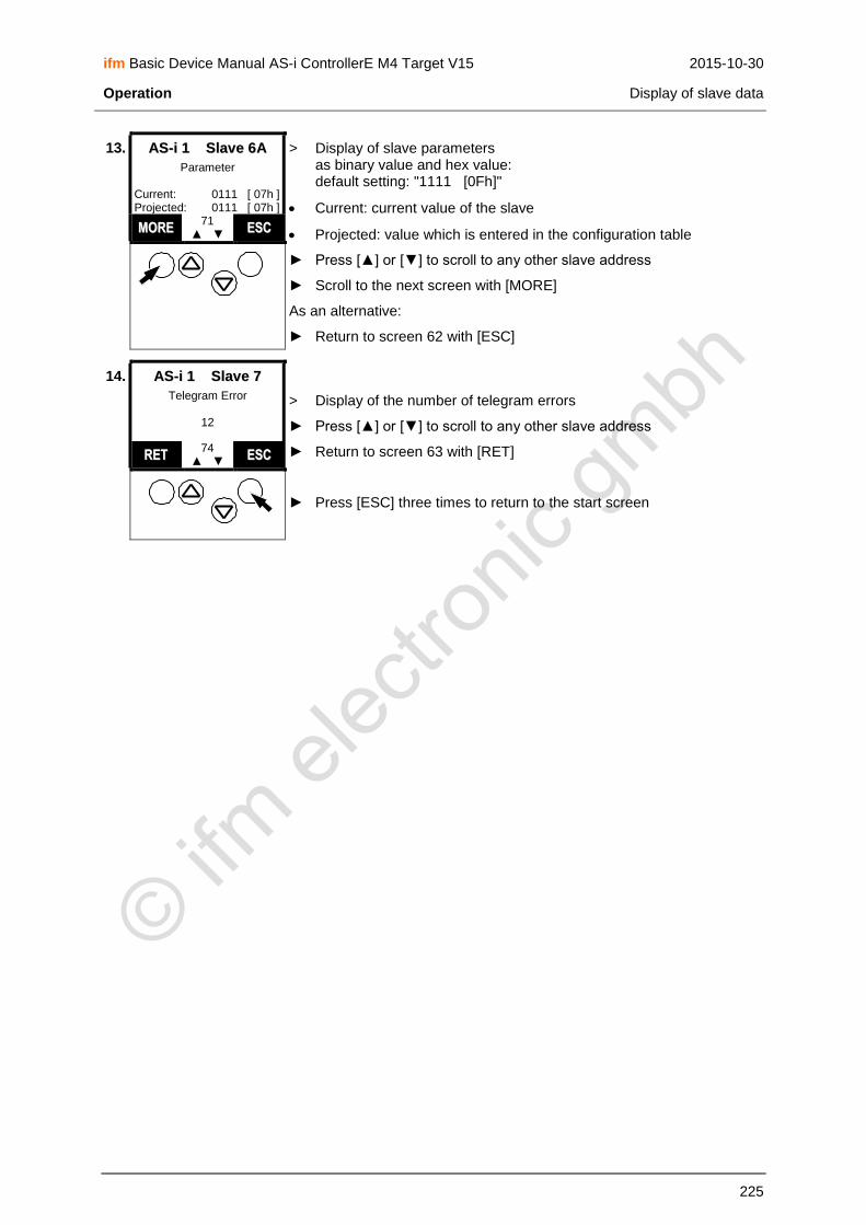
ifm Basic Device Manual AS-i ControllerE M4 Target V15 2015-10-30
Operation Display of slave data
225
13. AASS--ii 11 SSllaavvee 66AA
Parameter Current: 0111 [ 07h ] Projected: 0111 [ 07h ]
> Display of slave parameters as binary value and hex value: default setting: "1111 [0Fh]"
Current: current value of the slave
Projected: value which is entered in the configuration table
► Press [▲] or [▼] to scroll to any other slave address
► Scroll to the next screen with [MORE]
As an alternative:
► Return to screen 62 with [ESC]
MMOORREE 71
▲ ▼ EESSCC
14. AASS--ii 11 SSllaavvee 77
Telegram Error
12
> Display of the number of telegram errors
► Press [▲] or [▼] to scroll to any other slave address
► Return to screen 63 with [RET]
► Press [ESC] three times to return to the start screen
RREETT 74
▲ ▼ EESSCC

ifm Basic Device Manual AS-i ControllerE M4 Target V15 2015-10-30
Operation Set output values
226
13.23 Set output values
For testing it can be useful to set the value of an output without influence by the PLC program. The controllere helps you.
WARNING
Risk of personal injury! Risk of material damage to the machine/plant! After the change of the slave outputs the output values remain unchanged.
The output values only change in the following cases:
Manual new setting of the outputs via Slave Setup
Starting the PLC program - the program processes the outputs
Switching the controllere off and on again
► Secure the concerned area.
► Only trained personnel is allowed to set outputs manually.
► Switch the outputs off again immediately after the end of the test.
NOTE
Password level 2 required → page 142, chapter Password setting
NOTE
Changes to the outputs are not effective in the following cases:
The PLC is in the RUN mode (LED [PLC RUN] lights).
AND: The corresponding outputs are processed by the PLC.
Changes of digital outputs on analogue modules.
Changes of analogue outputs on digital modules.
► Switch PLC to the operating mode STOP → page 118, chapter How are the operating modes for the PLC selected?
> LED [PLC RUN] flashes
[MENU] > [Slave Setup] > select master > select slave
1.
► Press the key [MENU] MMEENNUU 0 UUSSEERR

ifm Basic Device Manual AS-i ControllerE M4 Target V15 2015-10-30
Operation Set output values
227
2. Quick Setup
PLC Setup
Slave Lists
► Press [▼] to scroll to [Slave Setup] OOKK 1
▲ ▼ EESSCC
3. Fieldbus Setup
Slave Info
Slave Setup
► Select [Slave Setup] with [OK] OOKK 1
▲ ▼ EESSCC
4. SSllaavvee SSeettuupp ooff
AS-i Master 1
AS-i Master 2
► If necessary, press [▼] to scroll to AS-i master 2 OOKK 149
▲ ▼ EESSCC
5. SSllaavvee SSeettuupp ooff
AS-i Master 1
AS-i Master 2
► Select requested AS-i master with [OK] OOKK 149
▲ ▼ EESSCC
6. AASS--ii MMaasstteerr 11
SSeelleecctt SSllaavvee
66AA > Display of the lowest found valid slave address
► If necessary, press [▲] or [▼] to scroll to another slave address OOKK
150 ▲ ▼ EESSCC

ifm Basic Device Manual AS-i ControllerE M4 Target V15 2015-10-30
Operation Set output values
228
7. AASS--ii MMaasstteerr 11
SSeelleecctt SSllaavvee
66AA
► Select requested slave with [OK] OOKK 150
▲ ▼ EESSCC
Continue with: Set digital output → page 229
Continue with: Set analogue output → page 231

ifm Basic Device Manual AS-i ControllerE M4 Target V15 2015-10-30
Operation Set output values
229
13.23.1 Set digital output
8. AASS--ii 11 SSllaavvee 66AA
Digital output
Parameter value
► Select [Digital output] with [OK] OOKK 151
▲ ▼ EESSCC
9. DDiiggiittaall oouuttppuutt
AASS--ii 11 SSllaavvee 66AA
Current: 0000 [ 00h ] Setup: 0000 [ 00h ]
> Current = digital outputs current value binary / hexadecimal
> Setup = digital outputs setup value binary / hexadecimal
► Press [▲] or [▼] to set the requested setup value
SSEETT 153
▲ ▼ EESSCC
10. DDiiggiittaall oouuttppuutt
AASS--ii 11 SSllaavvee 66
Current: 0000 [ 00h ] Setup: 0010 [ 02h ] > Setup = set setup value
► Transmit setup value set with [SET] to the outputs of the slave SSEETT
153 ▲ ▼ EESSCC
11. DDiiggiittaall oouuttppuutt
AASS--ii 11 SSllaavvee 66AA
Current: 0010 [ 02h ] Setup: 0010 [ 02h ]
> Value in "Current" adopts value from "Setup"
> Outputs on the slave are switched accordingly. Set outputs remain switched until a new setup or start of the PLC changes the outputs again.
► Set setup value "0000" with [▼]
SSEETT 153
▲ ▼ EESSCC
12. DDiiggiittaall oouuttppuutt
AASS--ii 11 SSllaavvee 66AA
Current: 0010 [ 02h ] Setup: 0000 [ 00h ]
► Transmit the setup value set with [SET] to the outputs of the slave SSEETT 153
▲ ▼ EESSCC

ifm Basic Device Manual AS-i ControllerE M4 Target V15 2015-10-30
Operation Set output values
230
13. DDiiggiittaall oouuttppuutt
AASS--ii 11 SSllaavvee 66AA
Current: 0000 [ 00h ] Setup: 0000 [ 00h ]
> Value in "Current" adopts value from "Setup"
> Outputs on the slave are switched accordingly. Set outputs remain switched until a new set-up or start of the PLC changes the outputs again.
► Press [ESC] twice to return to screen 150
SSEETT 153
▲ ▼ EESSCC

ifm Basic Device Manual AS-i ControllerE M4 Target V15 2015-10-30
Operation Set output values
231
13.23.2 Set analogue output
8. AASS--ii 11 SSllaavvee 99
Digital output
Parameter value
► Press [▼] to scroll to [Analogue value] OOKK 151
▲ ▼ EESSCC
9. AASS--ii 11 SSllaavvee 99
Parameter value
Analogue value
► Select [Analogue value] with [OK] OOKK 151
▲ ▼ EESSCC
10. AAnnaalloogguuee vvaalluuee
AS-i Slave 9
Analogue channel 1
► Press [▲] to scroll to the requested analogue channel OOKK 152
▲ ▼ EESSCC
11. AAnnaalloogguuee vvaalluuee
AS-i Slave 9
Analogue channel 1
► Select requested analogue channel with [OK] OOKK 152
▲ ▼ EESSCC
12. AAnnaalloogguuee oouuttppuutt
AS-i 1 Slave 9 Channel: 2 Current: +0 Setup: +0
> Current = analogue output channel current value
> Setup = analogue output channel setup value
► Press [▲] or [▼] to set requested setup value Brief pressing: step increment 1 Long pressing: step increment 100
SSEETT 155
▲ ▼ EESSCC

ifm Basic Device Manual AS-i ControllerE M4 Target V15 2015-10-30
Operation Set output values
232
13. AAnnaalloogguuee oouuttppuutt
AS-i 1 Slave 9 Channel: 2 Current: +0 Setup: +604 > Setup = set setup value
► Transmit setup value set with [SET] to the outputs of the slave SSEETT
155 ▲ ▼ EESSCC
14. AAnnaalloogguuee oouuttppuutt
AS-i 1 Slave 9 Channel: 2 Current: +604 Setup: +604
> Display in "Current" adopts value from "Setup"
> Outputs on the slave are switched accordingly. Set outputs remain switched until a new setup or start of the PLC changes the outputs again.
► Press [▼] to set the setup value "0"
SSEETT 155
▲ ▼ EESSCC
15. AAnnaalloogguuee oouuttppuutt
AS-i 1 Slave 9 Channel: 2 Current: +604 Setup: +0
► Transmit setup value set with [SET] to the outputs of the slave SSEETT 155
▲ ▼ EESSCC
16. AAnnaalloogguuee oouuttppuutt
AS-i 1 Slave 9 Channel: 2 Current: +0 Setup: +0
> Display in "Current" adopts value from "Setup"
> Outputs on the slave are switched accordingly. Set outputs remain switched until a new setup or start of the PLC changes the outputs again.
► Press [ESC] twice to return to screen 150
SSEETT 155
▲ ▼ EESSCC

ifm Basic Device Manual AS-i ControllerE M4 Target V15 2015-10-30
Operation Display system parameters
233
13.24 Display system parameters
Here the controllere gives you all the information it has about itself.
[MENU] > [System Info]
1.
► Press the key [MENU] MMEENNUU 0 UUSSEERR
2. Quick Setup
PLC Setup
Slave Lists
► Scroll to [System Info] with [▼] OOKK 1
▲ ▼ EESSCC
3. Slave Setup
System Setup
System Info
► Press [OK] to select [System Info] OOKK 1
▲ ▼ EESSCC
4. Version
Hardware: . . . . . . .
RTS 2.207B
AS-i 1 0.237C
AS-i 2 . . . . . . .
IFM PBus DP: 0000
> Display of system versions:
Indication of the hardware version
Operating system version of the controllere
Operating system version for master 1
Operating system version for master 2
The integrated fieldbus is Profibus DP with the indication of the ifm version
► Scroll to the next screen with [MORE]
As an alternative:
► Scroll to screen 1 with [MENU] (main menu)
MMOORREE 40 MMEENNUU

ifm Basic Device Manual AS-i ControllerE M4 Target V15 2015-10-30
Operation Display system parameters
234
5. Version cont.
RTS Checksum: 1EB0
CONST Checksum: 0479
Linux Kernel: +0
Linux RAM disk: 0 . 0
> Display of system versions: 2nd screen
Checksum of the operating system
Checksum of the system constants
Version of the kernel of the Linux operating system
Version of the Linux memory driver
► Scroll to the next screen with [MORE]
As an alternative:
► Scroll to screen 1 with [MENU] (main menu)
MMOORREE 40 MMEENNUU
6. SSeerriiaall NNoo
6655AA3355DDAA1111000011 > Display of the serial number of the controllere
► Scroll to next screen with [OK]
As an alternative:
► Scroll to screen 1 with [MENU] (main menu)
OOKK 41 MMEENNUU
NOTE
For more displays: Password level 3 required →page142, chapter Password setting
7. Slave Setup
System Setup
System Info
► Return to start screen with [ESC]
> That's it! OOKK
1 ▲ ▼ EESSCC

ifm Basic Device Manual AS-i ControllerE M4 Target V15 2015-10-30
Scale drawing
235
14 Scale drawing
14.1
107
97
86
LED
62
2
1
3
Figure: dimensions of the controllere

ifm Basic Device Manual AS-i ControllerE M4 Target V15 2015-10-30
Technical data General data
236
15 Technical data
15.1 General data
Operating voltage 20...30 V DC (PELV)
Current consumption < 0.5 A (depending on the implemented options)
Operating temperature 0...+60 °C
Storage temperature -20...+70 °C
Protection rating to DIN 40050 IP 20
Housing material Aluminium, galvanised steel
Fixing on 35 mm Din rail
Housing dimensions 106.3 x 85.5 x 123.6 mm
15.2 Data AS-i master
Number of AS-i masters 1 (standard) or 2 (optional)
AS-Interface profile M4 according to version 3.0
AS-Interface voltage 26.5...31.6 V (special AS-i power supply)
Current consumption from AS-i 0.01 A / master
Microcontroller Infineon C1610 microcontroller
Supported V2.1 features A/B slaves
Periphery fault detection
Analogue plug + play (profiles 7.3 / 7.4 / CTT1)
Extended ID codes
Supported V3.0 features CTT2…CTT5
Other features AS-i cycle counter
Communication error counter per slave
Configuration error counter
Change to the protected mode without resetting the AS-i system

ifm Basic Device Manual AS-i ControllerE M4 Target V15 2015-10-30
Technical data Data serial interface RS-232C
237
15.3 Data serial interface RS-232C
Baud rates 9 600, 19 200, 38 400, 57 600, 115 200 bits/s
Communication parameters 8 data bits, no start bit, 1 stop bit, no parity
Connection RJ11 Western socket, 6-pole
Protocol Automation Alliance standard protocol
15.4 Data PLC
Microcontroller Infineon C165 microcontroller
SRAM 1 Mbyte
Flash memory 1 Mbyte
PLC program memory 228 kbytes
Program size up to 19000 commands in IL (simple binary commands)
Data memory 196 kbytes
Remanent flags 160 bytes %MW0...%MW79
Retain area 2 kbytes (stored by PLC command)
Programming languages Instruction list
Function block diagram
Ladder diagram
Sequential function chart
Continuous function chart
Structured text
All languages according to IEC 61131-3
POUs Programs
Functions
Function blocks
Operations Binary combinations
Arithmetic
Moving and rotating
Comparisons
Mathematical functions
Text processing
Jumps and return

ifm Basic Device Manual AS-i ControllerE M4 Target V15 2015-10-30
Technical data Data PLC
238
Data types Binary
Fixed point (byte, word, double word)
Floating point
String
Array
Structure
Pointer
Date and time
Processing times < 1s for simple bit or integer operations
Flags 4096 bits (= 256 bytes), of these bits 1280 bits remanent (= 160 bytes)
Approx. 190 kbytes can be addressed symbolically
Timers > 300
Counters > 300
Binary inputs (AS-i) max. 496
Binary outputs (AS-i) max. 496
Analogue inputs (AS-i) max. 248 channels
Analogue outputs (AS-i) max. 248 channels

ifm Basic Device Manual AS-i ControllerE M4 Target V15 2015-10-30
Error description Data PLC
239
16 Error description
There are 2 differents types of error messages in the controllere:
Handling errors and internal system errors:
Menu operation interrupted.
Error message superposes menu screen.
Error message only disappears after the following actions: 1. Error removed AND 2. error message acknowledged with the right function key.
Boot errors (error codes E10...E30):
Error message appears instead of the start screen.
No interruption of the menu operation.
Exclamation mark flashes in the text/graphics display in the middle of the line at the bottom (only if configuration mode is deactivated).
The error message disappears again as soon as the error has been corrected.
The following tables are sorted in groups by error code.

ifm Basic Device Manual AS-i ControllerE M4 Target V15 2015-10-30
Error description Boot errors: error codes B00...B11
240
16.1 Boot errors: error codes B00...B11
Menu operation interrupted.
Error message superposes menu screen.
Error message only disappears after the following actions: 1. Error removed AND 2. error message acknowledged with the right function key.
Error message Cause(s) Remedy
B00 Controller Boot error
After power-on of the device, an error was found during initialisation of the individual device components.
For further details please refer to the following error messages.
► Check further error messages.
B01 Master initialization
Failed initialisation of the masters.
Possible causes:
Unacceptable interference on the 24 V power supply.
Unacceptable interference on the AS-i power supply.
Unacceptably high electrostatic charges and electromagnetic fields in close proximity of the device.
► Grounding the device via the rail.
► Connection of the FE terminal to the machine ground.
► Use of a switched-mode power supply to supply the device.
B02 Master2 initialization → B01
B03 General FAT failure
An error was found in the data field of the "File Allocation Table" FAT.
► Check further error messages.
B04 Only one master detected
The operating system can only detect 1 master in the controllere although
communication with 2 masters must be possible.
Possible causes: hardware fault.
► Replace controllere and project
again.
B05 Two masters detected
The operating system can detect 2 masters in the controllere although
communication with only 1 master is allowed.
Possible cause: hardware fault.
► Replace controllere and project
again.
B06 Fieldbus type not expected
During the automatic detection of the integrated fieldbus no enabled fieldbus module could be detected.
Possible cause: hardware fault.
► Replace controllere and project
again.

ifm Basic Device Manual AS-i ControllerE M4 Target V15 2015-10-30
Error description Boot errors: error codes B00...B11
241
Error message Cause(s) Remedy
B07 Number of master mismatch
When the version releases of the masters were checked some invalid information was received.
Possible cause: Hardware fault.
► Replace controllere and project
again.
B08 Exec. of PLC blocked by user
When the device was started the automatic start of the PLC program was disabled by the user. The left function key of the device was pressed during power-on.
► Release function key during power-on.
or:
► No action because this is requested.
B09 Reserved ––
B10 Master 1 firmware obsolete
The AS-i master firmware does not contain functions required for the RTS operating system.
► Updating the AS-i master firmware to the required minimum version.
B11 Master 2 firmware obsolete
→ B10 → B10

ifm Basic Device Manual AS-i ControllerE M4 Target V15 2015-10-30
Error description AS-I system errors: error codes E10...E32
242
16.2 AS-I system errors: error codes E10...E32
Error message appears instead of the start screen.
No interruption of the menu operation.
Exclamation mark flashes in the text/graphics display in the middle of the line at the bottom (only if configuration mode is deactivated).
The error message disappears again as soon as the error has been corrected.
Error message Cause(s) Remedy
E10 Slave not activated
The slave was detected in the system but not activated by the master.
Detected slave profile does not correspond to the projected slave profile and the master is in the "protected mode".
► Check slave profile: [Menu] > [Slave Info]:
→ page 222, chapter Display of slave data
► Connect slave with the right profile.
► Project slaves again: [Menu] > [Quick Setup]:
→ page 134, chapter Finish configuration
E11 Slave not present
Slave is indicated in the "list of projected slaves" LPS but not detected on the AS-i master.
► Check slave connections.
► Connect slave again.
E12 Slave not projected
Slave was detected on the AS-i bus but is missing in the "list of projected slaves" LPS.
► Project slaves again: [Menu] > [Quick Setup]:
→ page 134, chapter Finish configuration
E13 Periphery fault detected → page 186, chapter Display of slaves with periphery fault (list)
→ page 189, chapter Display of slave with periphery fault
E14 Safety slave alert Error message not active at present.
E15 CTT1 analog protocol failure Error message not active at present.
E20 ASI Power Fail
The master is in the "protected mode" and detects that the AS-i voltage supply is not higher than 28 V.
This message is only generated if at least one slave is projected.
► Check AS-i voltage supply on the master and replace, if necessary.
E21 No slave detected
The master is in the "protected mode" and detects that no slave is connected to the AS-i bus.
This message is only generated if at least one slave is projected.
► Check slave connections.
► Check AS-i line.

ifm Basic Device Manual AS-i ControllerE M4 Target V15 2015-10-30
Error description AS-I system errors: error codes E10...E32
243
Error message Cause(s) Remedy
E22 Slave 0 detected
The master is in the "protected mode" and detects a slave with the address 0 on the AS-i bus.
This message is only generated if the profile of the missing slave on the AS-i bus is identical to the profile of the slave with the address 0.
► Change master to "configuration mode":
→ page 116, chapter How are the operating modes for the AS-i master selected?
E23 Slave 0 bad profile
The master is in the "protected mode" and detects a slave with the address 0 on the AS-i bus.
This message is only generated if the profile of the missing slave on the AS-i bus is different from the profile of the slave with the address 0.
► Check and replace slave.
► Project slaves again: [Menu] > [Quick Setup]
→ page 134, chapter Finish configuration
E24 Autoaddress not enabled
The master is in the "protected mode" and detects a slave with the address 0 on the AS-i bus.
This message is only generated if the profile of the missing slave on the AS-i bus is identical to the profile of the slave with the address 0, the "automatic addressing" in the master, however, was not activated.
► Activate "automatic addressing" in the master:
→ page 127, chapter Automatic addressing of individual slaves
E25 Config. error
The master is in the "normal operating mode" and detects a projection error.
Possible causes:
The profiles of the detected slaves are different from those of the projected slaves.
One or more slaves are additionally detected on the AS-i bus.
One or several slaves are missing on the AS-i bus.
► Check the detected and projected slave profile in the menu [Slave Info].
→ page 222, chapter Display of slave data
► Check the entries of slaves in the lists LAS, LDS, LPS, LPF in the menu [Slave Lists].
→ page 178, chapter Display of detected slaves (list)
→ page 180, chapter Display of projected slaves (list)
→ page 183, chapter Display of active slaves (list)
→ page 186, chapter Display of slaves with periphery fault (list)
E26 Generic Periphery fault
The master is in the "mormal operating mode" and detects that at least one slave on the AS-i bus signals a periphery fault.
→ page 186, chapter Display of slaves with periphery fault (list)
→ page 189, chapter Display of slave with periphery fault

ifm Basic Device Manual AS-i ControllerE M4 Target V15 2015-10-30
Error description AS-I system errors: error codes E10...E32
244
Error message Cause(s) Remedy
E27 Normal operation inactive
The master signals that it is not in the "normal operating mode".
Possible causes:
1. When booting the system no slave was connected to the device or no slave was projected.
► Connect at least 1 slave to the device and reboot the system.
2. The master detects an AS-i voltage below 22 V and therefore goes into the "offline mode".
► Check AS-i voltage supply on the master and replace, if necessary.
3. The master received a request from the operating system to change to the "offline mode".
► Check AS-i voltage supply on the master and replace, if necessary.
4. The master found a transfer error in the communication with the operating system.
► Switch PLC off and on again.
► Replace controllere and project
again.
Other causes which can lead to an error message directly after power-on:
5. Initialisation of the master after power-on of the device was not successful.
► Switch PLC off and on again.
► Replace controllere and project
again.
6. The master has not yet received the projection nor the projected parameters from the operating system.
► Wait.
► If too long: → 5.
7. The master has not yet been started by the operating system.
► Wait.
► If too long: → 5.
E28 State PLC cmd channel
Command channel detects an invalid state.
► Check the request of the PLC command channel (1st word).
E29 Unknown MUX field identifier
The transmission between AS-I master and PLC processor has been deranged.
► Check data accesses via pointers into area < 4000h of your PLC program.
► Check the electrical environment about unacceptable high electro-magnetic fields and static charging.
► Check the grounding of the device.
E30 Safety slave triggered (1)
The first safety contact of the specified AS-I slave is opened.
► Bring the slave into the safe state.
E31 Safety slave triggered (2)
The second safety contact of the specified AS-I slave is opened.
► Bring the slave into the safe state.

ifm Basic Device Manual AS-i ControllerE M4 Target V15 2015-10-30
Error description AS-I system errors: error codes E10...E32
245
Error message Cause(s) Remedy
E32 Safety slave triggered (1/2)
The master detected a "safe slave" on the AS-i line whose inputs are constantly switched to LOW for a period > 64 ms.
► Bring the slave into the safe state.

ifm Basic Device Manual AS-i ControllerE M4 Target V15 2015-10-30
Error description FAT errors: Error codes F01...F10
246
16.3 FAT errors: Error codes F01...F10
FAT = File Allocation Table (part of the memory management)
Menu operation interrupted.
Error message superposes menu screen.
Error message only disappears after: 1. Error removed AND 2. Error message acknowledged with the right function key.
Error message Cause(s) Remedy
F01 Bad FAT checksum
The checksum of the FAT contains an invalid value.
Possible cause: unacceptable interference on the 24 V supply during the storage operation of the data in the flash memory.
► Grounding the device via the rail.
► Connection of the FE terminal to the machine ground.
► Use of a switched-mode power supply to supply the device.
► Repeat command.
F02 Bad FAT header
The identifier in the header of the FAT contains an invalid entry.
Possible cause: unacceptable interference on the 24 V supply during the storage operation of the data in the flash memory.
→ F01
F03 Bad FAT ID
The field ID of a FAT area contains an invalid value.
Possible cause: unacceptable interference on the 24 V supply during the storage operation of the data in the flash memory.
→ F01
F04 Virgin FAT found
The FAT contains no entry.
Possible cause: The user completely deleted the flash memory.
► Replace the device and project again.
F05 Bad NV field checksum
The checksum of the remanent data within the FAT contains an invalid value.
Possible cause: unacceptable interference on the 24 V supply during the storage operation of the data in the flash memory.
► Grounding the device via the rail.
► Connection of the FE terminal to the machine ground.
► Use of a switched-mode power supply to supply the device.
► Repeat command.
F06 Bad NV field ID
The field ID of the remanent data contains an invalid value.
Possible cause: unacceptable interference on the 24 V supply during the storage operation of the data in the flash memory.
→ F05

ifm Basic Device Manual AS-i ControllerE M4 Target V15 2015-10-30
Error description FAT errors: Error codes F01...F10
247
Error message Cause(s) Remedy
F07 NV pointer invalid range
The start address of the remanent data is outside the permitted area.
Possible cause: unacceptable interference on the 24 V supply during the storage operation of the data in the flash memory.
→ F05
F08 FAT storage
An error occurred during the storage of the FAT.
Possible cause: unacceptable interference on the 24 V supply during the storage operation of the data in the flash memory.
→ F05
F09 NV field storage
An error occurred during the storage of the remanent data.
Possible cause: unacceptable interference on the 24 V supply during the storage operation of the data in the flash memory.
► Repeat command.
F10 General NV mirror switching
When changing to the mirror area of the remanent data a fault has occurred.
Possible causes: unacceptable interference on the 24 V supply during the storage operation of the data in the flash memory.
► Repeat command.

ifm Basic Device Manual AS-i ControllerE M4 Target V15 2015-10-30
Error description Flash errors: error codes F20...F30
248
16.4 Flash errors: error codes F20...F30
Menu operation interrupted.
Error message superposes menu screen.
Error message only disappears after: 1. Error removed AND 2. error message acknowledged with the right function key.
Error message Cause(s) Remedy
F20 General flash error
This error message contains all failed operations which have to do with the integrated flash memory.
For further details see the following error messages.
► Check further error messages.
F21 Bad flash command
The operating system received an invalid command for the flash memory.
Possible cause: error in the PLC command
► Check and correct command.
► Repeat command.
F22 Flash sector erasure
The flash memory did not meet the request to delete a flash sector.
Possible cause: access to the flash memory which is currently processing commands.
► Repeat command.
F23 Flash write verify failed
The data to be stored in the flash memory could not be verified.
Possible cause: access to the flash memory which is currently processing commands.
► Repeat command.
F24 Flash device: timeout
The flash memory signals timeout during the execution of a command.
Possible cause: access to the flash memory which is currently processing commands.
► Repeat command.
F25 Flash device: command
The flash memory received an invalid command.
Possible cause: software error in the operating system.
► Check and correct command.
► Repeat command.
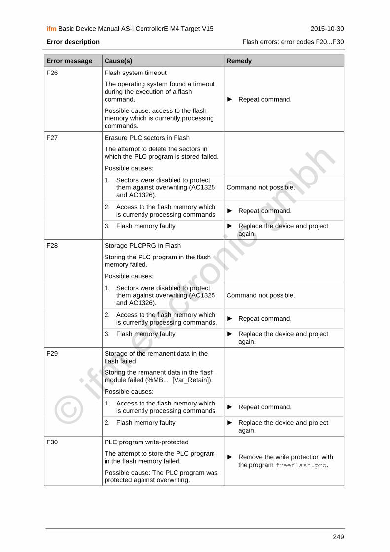
ifm Basic Device Manual AS-i ControllerE M4 Target V15 2015-10-30
Error description Flash errors: error codes F20...F30
249
Error message Cause(s) Remedy
F26 Flash system timeout
The operating system found a timeout during the execution of a flash command.
Possible cause: access to the flash memory which is currently processing commands.
► Repeat command.
F27 Erasure PLC sectors in Flash
The attempt to delete the sectors in which the PLC program is stored failed.
Possible causes:
1. Sectors were disabled to protect them against overwriting (AC1325 and AC1326).
Command not possible.
2. Access to the flash memory which is currently processing commands
► Repeat command.
3. Flash memory faulty ► Replace the device and project again.
F28 Storage PLCPRG in Flash
Storing the PLC program in the flash memory failed.
Possible causes:
1. Sectors were disabled to protect them against overwriting (AC1325 and AC1326).
Command not possible.
2. Access to the flash memory which is currently processing commands.
► Repeat command.
3. Flash memory faulty ► Replace the device and project again.
F29 Storage of the remanent data in the flash failed
Storing the remanent data in the flash module failed (%MB... [Var_Retain]).
Possible causes:
1. Access to the flash memory which is currently processing commands
► Repeat command.
2. Flash memory faulty ► Replace the device and project again.
F30 PLC program write-protected
The attempt to store the PLC program in the flash memory failed.
Possible cause: The PLC program was protected against overwriting.
► Remove the write protection with
the program freeflash.pro.

ifm Basic Device Manual AS-i ControllerE M4 Target V15 2015-10-30
Error description Information errors: error code I01
250
16.5 Information errors: error code I01
Menu operation interrupted.
Error message superposes menu screen.
Error message only disappears after: 1. Error removed AND 2. error message acknowledged with the right function key.
Error message Cause(s) Remedy
I01 Flash Sector switched
The runtime system RTS changed to another flash sector to store the remanent data.
No error, just a message for the user.

ifm Basic Device Manual AS-i ControllerE M4 Target V15 2015-10-30
Error description AS-i master command errors: error codes M01...M44
251
16.6 AS-i master command errors: error codes M01...M44
Menu operation interrupted.
Error message superposes menu screen.
Error message only disappears after: 1. Error removed AND 2. error message acknowledged with the right function key.
Error message Cause(s) Remedy
M01 Command execution error
During the execution of an AS-i command an error occurred which prevented execution.
For further details see the following error messages.
► Check further error messages.
M02 Slave not found
An attempt was made to access a slave with an AS-i command which is not on the AS-i bus. The slave is not in the LDS.
► Check slave connections .
► Connect slave again.
M03 Slave 0 found
The master detects a slave with the address 0 on the AS-i bus and can therefore not execute the command.
Example: The address of a slave is to be changed while a slave with the address 0 is present on the AS-i bus.
► Remove slave with the address 0 or address correctly.
M04 Slave with same address found
During the execution of a command the master detects that there is already a slave at the requested address on the AS-i bus.
Example: The address of a slave is to be changed to an address which is already assigned to another slave on the AS-i bus.
► Remove one of the slaves with double address.
► Readdress the remaining slave.
► Connect removed slave again.
M05 Delete of old slave address
The attempt to reprogram a slave to address 0 failed.
Example: AS-i slave has a limited number of possibilities to change the address, these are now exhausted.
► Replace slave.
M06 Reading Extended ID Code 1
The master receives no or no valid response when reading the "Extended ID code 1".
Example: attempt to readdress an A/B slave to another address.
► Repeat command.

ifm Basic Device Manual AS-i ControllerE M4 Target V15 2015-10-30
Error description AS-i master command errors: error codes M01...M44
252
Error message Cause(s) Remedy
M07 Writing to slave failed:
1. The attempt of the master to readdress a slave to the new target address failed.
► Repeat command.
2. Writing the "extended ID code 1" to slave 1 failed. Example: attempt to readdress an A/B slave to another address.
► Repeat command.
M08 New address temporary stored
During the readdressing of a slave the new address could not be written to the slave because the slave is no longer detected on the AS-i bus.
Possible causes:
1. Double addressing ► Remove one of the slaves with double address.
► Readdress remaining slave.
► Connect removed slave again.
2 Major bus interference ► Remove cause of the interference.
M09 Extended ID1 temporary stored
While writing the "ID Code 1" to the slave the code could not be written to the slave because the slave is no longer detected on the AS-i bus.
Possible causes:
1. Double addressing ► Remove one of the slaves with double address.
► Readdress remaining slave.
► Connect removed slave again.
2. Major bus interference ► Remove cause of the interference.
M10 Slave not in LAS
The master detects that a slave has not been activated.
Possible causes: The slave profile in the projection data is not identical to the profile of the detected slave and the master is in the "protected mode”.
► Change master to the "configuration mode":
→ page 116, chapter How are the operating modes for the AS-i master selected?
► Check and replace slave.
► Project slaves again: [Menu] > [Quick Setup]:
→ page 134, chapter Finish configuration

ifm Basic Device Manual AS-i ControllerE M4 Target V15 2015-10-30
Error description AS-i master command errors: error codes M01...M44
253
Error message Cause(s) Remedy
M11 Slave data invalid
This error message has a multiple meaning and depends on the requested command:
1. Slave readdressing Address 32 = 0B was indicated as target address.
Address 0B is not valid.
► Write valid address.
2. Write parameter The attempt was made to write a value greater than 7h to an A/B slave, ID=Ah.
► Write valid value.
M12 7.3/7.4 sequence failure
During the transfer according to the "7.4 slave protocol" the master detected an error in the triple sequence of the slave.
Possible causes:
1. Interference on the bus ► Remove cause of the interference.
2. Software error in the AS-i slave ► Contact the AS-i specialist or manufacturer.
M13 Host timeout on 7.4
During the transfer according to the "7.4 slave protocol" the master detected a timeout in the communication with the operating system.
Possible cause:
Long PLC cycle which unacceptably slows down the transfer of the individual 7.4 segments of the operating system or PLC to the master: t > 1 s.
If this occurs, the master ends the started 7.4 transfer and restarts the normal exchange of data with the concerned slave.
► Shorten PLC cycle by optimising the program.
► Avoid program loops and complex arithmetic operations.
M14 Invalid address
This error message has a multiple meaning and depends on the requested command:
1. The attempt was made to write a parameter to slave 0.
► Correct slave address.
2. During readdressing the address 0 or 0B was indicated as start and target address.
► Indicate valid address.
3. During the attempt to write the "extended ID code 1" the address 0 was used.
► Indicate valid address.

ifm Basic Device Manual AS-i ControllerE M4 Target V15 2015-10-30
Error description AS-i master command errors: error codes M01...M44
254
Error message Cause(s) Remedy
M15 Slave aborted 7.4
The addressed 7.4 slave stopped the transfer.
Possible cause: Error in the 7.4 data of the PLC.
Possible causes:
1. Interference on the bus ► Remove cause of the interference.
2. Software error in the AS-i slave ► Contact slave manufacturer.
M16 Slave deleted while 7.4 runs
During an active 7.4 protocol transfer the slave was deleted from the list of active slaves by the master.
Possible cause: interference on the bus.
► Remove cause of the interference.
M17 7.4 transfer busy
The attempt was made to start a new 7.4 transfer during an active 7.4 protocol transfer.
► Repeat command.
M18 7.4 Host sequence failure
The sequence bit was set to 1 by the host or the PLC although a value below 30 was indicated in the "Dlen" data field.
► Correct value "Dlen".
or:
► Change sequence bit.
M19 7.4 Invalid data length, not MOD 3 divisor
The indicated data length "Dlen" is no multiple of the factor 3.
► Correct value "Dlen"
A 7.4 protocol transfer always consists of several data triples.
M20 Unknown command
Master received an unknown command.
► Check the cause of the wrong command and correct.
M21 Safety monitor protocol error
During the processing of the safety monitor protocol a transmission error occurred.
Possible cause: interference on the bus
► Check and correct the cause of the wrong command.
M22 Timeout command ► Remove cause of the interference.
M23 Command preconditions failed
Missing the necessary requirements for the requested master command.
► Correct the concerning parameters.
M24…M32 Not defined Reserved
M33 Internal safety protocol error
Error during processing of the protocol of the safety monitor on the AS-i line, phase "Init A".
► Improve the transmission quality of the AS-I wiring.

ifm Basic Device Manual AS-i ControllerE M4 Target V15 2015-10-30
Error description AS-i master command errors: error codes M01...M44
255
Error message Cause(s) Remedy
M34 Internal safety protocol error
Error during processing of the protocol of the safety monitor on the AS-i line, phase "Init B".
► Improve the transmission quality of the AS-I wiring.
M35 Timeout on Safety Protocol
Timeout during processing of the protocol of the safety monitor on the AS-i line.
► Improve the transmission quality of the AS-I wiring.
M36 SubCmd invalid
The subcommand entry of the command _PCS_SAFETY_MONITOR is invalid.
► Use a permitted sub-command.
M37 Slaveaddress has no profile S-7.F.F
The slave to be added to the list "LPM" (list of projected monitors) does not have the allowed profile in the CDI data.
► Correct the slave address to this of a slave with profil S-7.F.
M38 Slaveaddress out of valid range 1..31
The slave to be added to the list "LPM" does not have the allowed address.
► Correct the slave address to a value 1…3110.
M39 LPM already full
The LPM list is already full so that no other entries can be added.
► Delete a non-used slave out of the LPM.
M40 Slaveaddress already in LPM ► Delete the slave out of the LPM.
M41 Slaveaddress not found in LPM ► Save the slave in the LPM.
M42 Monitor protocol changed
The protocol of the safety monitor was interrupted during processing.
Only information for user.
► The last received data may be not consistent und should be requested again.
M43 HostCmd loop timeout
Processing the command "_PCS_SAFETY_MONITOR" could not be started within the allowed time.
► Check the PLC command channel about a cyclical usage and interrupt this.
M44 Internal safety protocol error
During processing of the protocol of the safety monitor an error occurred in the internal "AS-i master state machine".
► AS-I master must be cofigured new.

ifm Basic Device Manual AS-i ControllerE M4 Target V15 2015-10-30
Error description RTS errors: error codes R01...R46
256
16.7 RTS errors: error codes R01...R46
RTS = RunTime System (operating system of the controllere)
Menu operation interrupted.
Error message superposes menu screen.
Error message only disappears after: 1. Error removed AND 2. error message acknowledged with the right function key.
Error message Cause(s) Remedy
R01 Unknown RTS operating mode
The set operating mode of the device ("RUN" / "STOP" / "GATEWAY") is unknown to the operating system.
Possible cause: modification of the device from a gateway variant into a device with PLC support.
► Switch off the device and keep the left function key pressed during the switch-on operation.
R02 Master1: MUX field failure
During the transfer of the MUX fields by the operating system the master detected an invalid field number.
Possible causes:
1. Overwriting parts of the operating system by the PLC
► Check the cause of the wrong command and correct.
► Reinstall the operating system.
2. Unacceptable interference on the 24 V supply
► Grounding the device via the rail.
► Connection of the FE terminal to the machine ground.
► Use of a switched-mode power supply to supply the device.
► Repeat command.
R03 Master2: MUX field failure → R02
R04 Master1: Protocol Error (EDET)
The master detected a protocol error during the transfer of the data fields.
→ R02
R05 Master2: Protocol Error (EDET) → R02
R06 General RTS program failure
The operating system detected an invalid status in the process while executing the program internally.
Possible cause: operating system software error.
► Reinstall the operating system.
R07 Projecting mode not active
The attempt was made to execute an AS-i command which is only allowed in the "configuration mode".
► Change master to the operating mode "configuration mode":
→ page 116, chapter How are the operating modes for the AS-i master selected?

ifm Basic Device Manual AS-i ControllerE M4 Target V15 2015-10-30
Error description RTS errors: error codes R01...R46
257
Error message Cause(s) Remedy
R08 No PLC program loaded
The attempt was made to start a PLC program although no program had been loaded to the controllere.
► Load PLC program to the controllere:
→ page 124, chapter Connect the programming device
R09 RS-232 frame error (Baudrate)
The hardware of the integrated serial interface chip found a transmission error in the RS-232C data flow.
Possible causes:
1. Baud rate setting in the controllere
is different from the setting in the PC.
► Adapt baud rate:
→ page 121, chapter Set the baud rate of the serial interface
2 Other programs (e.g. Messenger) are using the RS-232-interface of the PC
► Exit other programs on the PC.
R10 RS-232 buffer overflow
A buffer overflow was found in the serial receive buffer of the RS-232C interface.
Possible causes:
1. RS-232 telegram too long or baud rate too high
► Check driver or reduce baud rate.
2. Faulty connection cable between PC and RS-232C connection on the controllere
► Replace connection cable.
R11 RS-232 parity check
The parity check of the serial data flow of the RS-232C interface failed.
Possible cause: electromagnetic interference
► Reduce interference on the RS-232 cable by means of the following measures: - Screen cable - Reduce cable length - Remove interfering source
R12 ASC0 handler switched
The decoding of the serial data flow was changed.
Possible cause: during the serial data flow, command to change to the test mode / normal operating mode of the device.
► Remove error in the protocol driver.
R13 24V power unstable
During normal operation voltage drops below 18 V were found on the 24 V power supply cable.
► Stabilise the 24 V supply voltage so that it is permanently above 20 V.
Better:
► Use of the switched-mode power supply.

ifm Basic Device Manual AS-i ControllerE M4 Target V15 2015-10-30
Error description RTS errors: error codes R01...R46
258
Error message Cause(s) Remedy
R14 24V power fail restart
The voltage failure of the 24V power supply caused the device to start again.
► Acknowledge message
> Controllere resumes normal
operating mode.
In future:
► Stabilise the 24 V supply voltage so that it is permanently above 20 V.
Better:
► Use switched-mode power supply.
R15 C165 Watchdog timeout
The main processor found timeout.
Possible causes:
1. Unacceptable interference on the AS-i power supply
2. Unacceptably high electrostatic charges and electromagnetic fields in close proximity of the device
► Grounding the device via the rail.
► Connection of the FE terminal to the machine ground.
► Use of a switched-mode power supply to supply the device.
3. Hardware fault ► Replace controllere and project
again.
4. Operating software error ► Reinstall operating system.
R16 Software restart
The main processor detected a restart of the device which was not triggered by a voltage failure.
► Check cause, possibly supported by further error messages.
R17 Wait for 24V power
After power-on of the device an unacceptably low 24 V power supply of < 18 V was detected.
► Acknowledge message.
> Controllere resumes normal
operating mode.
In future:
► Stabilise the 24 V supply voltage so that it is permanently above 20 V.
Better:
► Use switched-mode power supply.
R18 Master1: Host WDT failure
During the continuous communication of the master with the operating system the master found a timeout.
Possible causes:
1. Voltage drops on the 24 V power supply cable
► Use switched-mode power supply to supply the device.
2. Operating system software error ► Reinstall operating system.
R19 Master2: Host WDT failure → R18

ifm Basic Device Manual AS-i ControllerE M4 Target V15 2015-10-30
Error description RTS errors: error codes R01...R46
259
Error message Cause(s) Remedy
R20 Only in AC1345/46, AC1355/56 and AC1365/66
Profibus DP configuration
The configuration of the Profibus master for the device is not valid.
Possible causes:
Module lengths incorrect
Number of modules incorrect
Sum of the data lengths across all modules too large
► Check received data lengths in the menu [Fieldbus Setup].
R21 Only in AC1345/46, AC1355/56 and AC1365/66
No ifm DP interface detected
A Profibus DP card is expected in the device, however, it was not detected.
Possible cause: wrong operating system in the device: e.g.: AC1325 operating system software in AC1311.
► Install valid operating system.
R22 Only in AC1345/46, AC1355/56 and AC1365/66
DP parameter invalid
The parameter setting of the Profibus master for the device is not valid.
Possible causes:
Structure of the parameter field incorrect
Length of the parameter field incorrect
Coding of the different parameters does not correspond to the specification
► Adopt parameter field from the GSD file and modify it according to the specification.
R23 Only in AC1345/46, AC1355/56 and AC1365/66
DP parameter download
The attempt to download the current / projected parameters of the AS-i slaves via the Profibus failed.
Possible causes:
The slave to which the parameter was to be written was deleted from the list of detected slaves.
During the execution of the AS-i command "Write Parameter" a timeout was detected.
► Disconnect from the Profibus master.
► Reestablish the connection to the Profibus master.
> Download the current / projected parameters of the AS-i slaves via the Profibus.

ifm Basic Device Manual AS-i ControllerE M4 Target V15 2015-10-30
Error description RTS errors: error codes R01...R46
260
Error message Cause(s) Remedy
R24 Missing positive CPTE edge
During communication with the master a change in the state of the control signal was not detected.
Possible cause: operating system software error.
► Reinstall operating system.
R25 Master1: Unnormal operation
The master signals that it is not in the "normal operating mode".
Possible causes:
1. The master detects an AS-i voltage below 22 V and therefore goes into the "offline mode".
► Use of a switched-mode power supply to supply the device.
2. The master received a request from the operating system to go to the "offline mode".
► Check cause of the wrong command and correct
3. The master found a transmission error in the communication with the operating system.
→ R15
4. Although connected to the AS-i power supply, the master found no slave on the AS-i bus.
► Check and correct wiring on the AS-i bus
Other causes which can lead to an error message directly after power-on:
5. Initialisation of the master during power-on of the device failed.
→ page240, error message B01
6. The master has not yet received the projection nor the projected parameters from the operating system.
→ page240, error message B01
7. The master has not yet been started by the operating system.
→ page240, error message B01
R26 Master2: Unnormal operation → R25
R27 Only for AC1305/06, AC1325/26
Profibus PLC access violation
The PLC tried to access the protected address area of Profibus DP ASIC.
Possible cause: A PLC project supporting an Anybus fieldbus card was loaded.
► Remove functions from the PLC project which control the Anybus card.
R28 Execution password protected.
A function of the device was requested which is not allowed with the currently active password.
► Select higher password level:
→ page 142, chapter Password setting

ifm Basic Device Manual AS-i ControllerE M4 Target V15 2015-10-30
Error description RTS errors: error codes R01...R46
261
Error message Cause(s) Remedy
R29 PC command unknown
Unknown command received in the operating mode "test mode" of the device.
► Check the cause of the wrong command and correct.
R30 PC checksum failure
In the operating mode "test mode" of the device an invalid checksum was found in the data flow.
► Configure data flow according to the specification.
R31 Menu not available
The selected menu could not be displayed.
Possible causes:
1. Required hardware is not available in the device
► Check data sheet.
2. Required hardware was not detected when switching on the operating system RTS
► Switch the device off and on again.
R32 RTS checksum failure
The checksum of the runtime system does not correspond to the stored checksum.
Possible causes:
1. Flash memory faulty ► Replace faulty device.
2. Strong ESD fields with unacceptable grounding of the device
► Minimise ESD fields.
► Correct grounding of the device.
R33 Only for AC1353/54
No ifm ENET module detected
The requierd Ethernet module could not be detected.
Possible cause: faulty device
► Replace faulty device.
R34 Error in font data
The data of the character set is not correct.
Possible causes:
1. No data is available in the areas where font data is expected.
► Store the font data at the correct area.
2. The expected formatting is not correct.
► Correct the formatting.

ifm Basic Device Manual AS-i ControllerE M4 Target V15 2015-10-30
Error description RTS errors: error codes R01...R46
262
Error message Cause(s) Remedy
R35 Error in menu text
Possible causes:
1. No data is available in the areas where menu text is expected.
► Store the menu text data at the correct area.
2. The expected formatting is not correct
► Check and correct the formatting.
R36 Error in User Language
Text of the user language is incorrect
► Check and correct the user language.
R37 Error in text format
The indicated text format is incorrect ► Check and correct the formatting.
R38 Only for AC1353/54
Command Request Eth.-Module
The command for the Ethernet module could not be executed.
Possible cause: No communication with the Ethernet module possible.
► Contact the AS-i specialist or manufacturer.
R39 Only for AC1353/54
Request Timeout Eth.-Module
Timeout occurred during the execution of a command of the Ethernet module.
► Repeat command.
R40 Const data checksum failure
A checksum error occurred in the const. areas (character sets, system language, user language) of the runtime system.
► Reinstall operating system.
R41 Only for AC1353/54
Zonetimeout DPRAM
Timeout occurred during the communication between the runtime system and the Ethernet interface via DPRAM
► Switch off device for approx. 2 s, then switch on again.
► If error accours again contact the AS-i specialist or manufacturer.
R42 State error Eth.-Module
The Ethernet interface has an invalid status.
→ R41
R43 Zonetimeout Netvar
A timeout occurred during the communicaton of the network-global variables between the runtime system and the Ethernet interface via DPRAM.
→ R41
R44 Invalid AS-i command
The via PLC command channel requested AS-I command number is not valid.
► Correct command number

ifm Basic Device Manual AS-i ControllerE M4 Target V15 2015-10-30
Error description RTS errors: error codes R01...R46
263
Error message Cause(s) Remedy
R45 Only in AC1345/46, AC1355/56 and AC1365/66
DP module 12 legal word access
In the configuration of the Profibus DP modules a bad value for the interface memory was detected.
► Correct memory address.
R46 Only in AC1345/46, AC1355/56 and AC1365/66
Internal DP stack error
► Send device to manufacturer.

ifm Basic Device Manual AS-i ControllerE M4 Target V15 2015-10-30
Error description Timeout errors: error codes T00...T13
264
16.8 Timeout errors: error codes T00...T13
Menu operation interrupted.
Error message superposes menu screen.
Error message only disappears after: 1. Error removed AND 2. error message acknowledged with the right function key.
Error message Cause(s) Remedy
T00 Timeout communication master
The operating system detected a timeout during communication with the master.
Possible causes:
Unacceptable interference on the 24 V power supply.
Unacceptable interference on the AS-i power supply.
Unacceptably high electrostatic charges and electromagnetic fields in close proximity of the device.
► Grounding of the device via the rail, connection of the FE terminal to the machine ground.
► Use of a switched-mode power supply to supply the device.
T01 Timeout system cycle
A system cycle took too long.
Possible cause: overwriting of parts of the operating system in SRAM by the PLC.
► Check the cause of the wrong command and correct.
T02 Timeout ASI1 cmd channel 1
The operating system detected a timeout during the execution of a command for master 1 on channel 1.
Possible cause: overwriting of the status information of the command channel by the PLC.
► Check the cause of the wrong command and correct.
T03 Timeout ASI1 cmd channel 2 → T02
T04 Timeout ASI2 cmd channel 1 → T02
T05 Timeout ASI2 cmd channel 2 → T02
T06 Timeout PLC cycle
A PLC cycle took too long.
Possible cause: closed loop within the PLC.
► Check the cause of the wrong command and correct.

ifm Basic Device Manual AS-i ControllerE M4 Target V15 2015-10-30
Error description Timeout errors: error codes T00...T13
265
Error message Cause(s) Remedy
T07 Timeout command channel
During the execution of a command started by the PLC a timeout was found.
Possible causes: overwriting of the status information of the command channel by the PLC or an installed fieldbus
► Check the cause of the wrong command and correct.
T08 Timeout command channel request
During the attempt to start a command on the command channel a timeout was detected.
Possible causes:
1. Overwriting of the status information of the command channel by the PLC. ► Check the cause of the wrong
command and correct. 2. Permanent use of the command
channel by the installed fieldbus
T09 Timeout Fieldbus communication
A timeout was detected during the communication of the device with the connected fieldbus. This monitoring is active after the device communicated via the connected fieldbus for the first time.
Possible causes:
1. Fieldbus master stopped communication.
► Check the cause of the wrong command and correct.
2. Connection cable interrupted. ► Check connection cable and correct.
T10 Timeout on master mode
Changing the master to another operating mode failed.
Possible cause: When changing to the "protected mode" the master detected a slave with the address 0 and therefore cannot change to this operating mode.
► Correct slave address.
► Repeat command.
T11 Timeout MUX actualisation
A timeout was found during the update of the MUX fields, e.g.: analogue values of the slaves 1..31.
Possible causes:
1. Overwriting of parts of the operating system by the PLC.
► Check the cause of the wrong command and correct.
2. Interference on the 24 V power supply cable.
► Use of a switched-mode power supply to supply the device.

ifm Basic Device Manual AS-i ControllerE M4 Target V15 2015-10-30
Error description Timeout errors: error codes T00...T13
266
Error message Cause(s) Remedy
T12 Only in AC1345/46, AC1355/56 and AC1365/66
Timeout send DP diagnosis
The DP user diagnosis could not be transmitted.
Possible causes:
1. Interference on the Profibus DP ► Check wiring of the Profibus system.
2. The DP master no longer exchanges data with the device
► Check function of the Profibus master and the connection.
T13 Only in AC1353/54/55/56
Timeout Glob.-Networkvariables
The network-global variables could not be received / transmitted within 1 s.
Possible causes:
Connection to host server lost.
Ethernet cable is no longer connected to the next Ethernet switch/hub.
► Check connection cables and terminals and correct.
► Controller using global networkvariables must be in run mode.
► Max. response time for UDP protocol must be < 200 ms.

ifm Basic Device Manual AS-i ControllerE M4 Target V15 2015-10-30
Error description List of errors
267
16.9 List of errors
Incorrect behaviour Cause(s) Remedy
The controllere does not display
the start screen after power-on.
> Text/graphics display blank or not readable
> LEDs light / flash mazily
Error in the contents of the PLC memory, e.g.: program error in the boot project
► Switch off the device
► Press the left function key and keep it pressed
► Switch on the device again
> Display can be read again
► Release the function key
> PLC memory and boot project are irretrievably deleted
► Check PLC program in the PC and correct
► Store PLC program in the controllere and create it as
boot project
Electromagnetic incompatibility
Voltage supply does not correspond to AS-i rule?
► Rectify
Grounding not as specified?
► Rectify
Strong interference by neighbouring machines?
► If possible: change location
► Rectify or screen interfering machines
The text/graphics display is shaded.
> Error message R16 appears.
AS-i supply voltage is < 18.2 V
Overload of the AS-i power supply: too many slaves on one AS-i bus
► Distribute slaves to several AS-i masters
► Each AS-i master needs its own power supply
The text/graphics display indicates nothing any more (only background illumination active). All other functions of the controllere are not affected.
System error
► Press [▲] and [▼] at the same time for approx. 2 s
> Text/graphics display is reinitialised
> Language selection is active
► Quit language selection with [ESC]

ifm Basic Device Manual AS-i ControllerE M4 Target V15 2015-10-30
Error description List of errors
268
Incorrect behaviour Cause(s) Remedy
The LDS slave list shows no slave with the address 0 although such a slave has just been connected.
At least one other slave with the address 0 is connected to the master.
► Remove last slave with the address 0 from the bus.
► Program the old slave with the address 0 to the intended address (→ page 127 or page 130).
► Connect the removed slave again.
► Reconfigure the controllere
→ page 134.
2 identical slaves with the same address on the AS-i master.
1. Application slave replacement:
Slave was replaced
The new slave did not have the address "0" before
> Red LED on the slave lights: slave was not correctly addressed.
> Error message on the master: "slave not present".
2. Application set-up:
Master in the configuration mode.
New slave addressed using handheld addressing unit and then connected.
> If the address is already occupied, the red LED on the slave lights: slave was not correctly addressed.
3. Application set-up:
Master not in configuration mode.
> For al readdressed and connected slaves the red LEDs light: slaves were not correctly addressed.
► Reconfigure controllere
→ page 134.
> If slaves with different profile: Red LED on the slave lights: slave was not correctly addressed.
> If slaves with the same profile: First everything ok until different input signals, then message "configuration error".
The controllere does not react to
the key being pressed or only with a long delay.
> Error messages R02 to R05
The cycle time of the PLC is > 300 ms. Other processes in the controllere have priority.
► Check and rectify PLC program.
When changing the address of A/B slaves the controllere
sometimes freezes in the "Wait" display.
System error. ► Quit the menu item with
[ESC] (= right key).

ifm Basic Device Manual AS-i ControllerE M4 Target V15 2015-10-30
Error description How does the controllere react in case of an error?
269
16.10 How does the controllere react in case of an error?
Errors displayed during operation Reaction
The slave is disconnected from the AS-i bus.
Slave without watchdog: Output signals remain unchanged.
Slave with watchdog: Outputs switched off.
AS-i master as PLC:
IMPORTANT: evaluate the slave failure in the PLC program. If necessary: stop the machine/plant.
The AS-i master is disconnected from the fieldbus.
AS-i master as gateway: Outputs switched off.
AS-i master as PLC: Input signals from the fieldbus master are reset. PLC triggers AS-i outputs with "0".
IMPORTANT: evaluate the fieldbus failure in the PLC program. If necessary: stop the machine/plant.
Controllere fails as fieldbus slave. Effect → description of the fieldbus master (host).

ifm Basic Device Manual AS-i ControllerE M4 Target V15 2015-10-30
Error description Hardware error, exception error
270
16.11 Hardware error, exception error
EExxcceeppttiioonn EErrrroorr
STKOV: STKUN: Seg: Off: SP: R0: CP: TFR:
> The main processor detected an exception error
> All current activities are interrupted
► Power the controllere off and on again
► If without success: Note down the displayed information and contact a sales specialist
OOKK
EESSCC
NOTE
If this error message is shown immediately after power-on, the execution of the PLC program can be prevented:
► During power-on press the left function key of the device and keep it pressed.
> The PLC program is declared "non valid", no longer initialised and no longer executed.
The following information in the TFR register provides details concerning the cause of the error:
TFR register
D15 D14 D13 D12 D11 D10 D9 D8 D7 D6 D5 D4 D3 D2 D1 D0
NM
I
ST
KO
F
ST
KU
F
–
–
–
–
–
UN
DO
PC
–
–
–
PR
TF
LT
ILLO
PA
ILLIN
A
ILL
BU
S
Bit Name Possible error source
NMI Non maskable interrupt Hardware
STKOF Stack overflow PLC program / hardware
STKUF Stack underflow PLC program / hardware
UNDOPC Unknown machine command PLC program / hardware
PRTFLT 32-bit execution code error PLC program / hardware
ILLOPA Invalid access to 16-bit operand PLC program / hardware
ILLINA Invalid jump address PLC program / hardware
ILLBUS Invalid access to external bus Hardware
Examples:
TFR 0004 Invalid access to 16-bit operand, e.g. by the PLC
TFR 0002 Invalid jump address, e.g. by the PLC
ifm Basic Device Manual AS-i ControllerE M4 Target V15 2015-10-30
Maintenance, repair and disposal Hardware error, exception error
271
17 Maintenance, repair and disposal
In case of correct use no maintenance and repair measures are necessary. Only the manufacturer is allowed to repair the device. If necessary, the device can be cleaned by qualified personnel using a dry cloth after disconnecting all connected circuits.
After use dispose of the unit in an environmentally friendly way in accordance with the applicable national regulations.

ifm Basic Device Manual AS-i ControllerE M4 Target V15 2015-10-30
Terms and abbreviations Hardware error, exception error
272
18 Terms and abbreviations
A/B slave →Slave with an A or B being appended to its address number and which is therefore allowed twice on →the master.
Address This is the "name" of the bus participant. All participants need a clearly defined unique address so that the signals can be exchanged without problem.
AS-i AS-i = actuator sensor interface
Bus system for the first binary field level.
ASIMON Software for configuration of the AS-i safety monitor
Download of the demo version: → www.ifm.com > Select country/language > [Service] > [Download] > [Bus system AS-Interface]
Baud Baud, abbrev.: Bd = unit of measurement for the data transmission speed. Do not confuse baud with "bits per second" (bps, bits/s). Baud indicates the number of changes of state (steps, cycles) per second over a transmission length. But it is not defined how many bits per step are transmitted. The name baud can be traced back to the French inventor J. M. Baudot whose code was used for telex machines.
1 MBd = 1024 x 1024 Bd = 1 048 576 Bd
Bus Serial data transmission of several participants on the same cable.
CAN CAN = Controller Area Network
CAN is a priority-controlled fieldbus system for larger data volumes. It is available in different variants, e.g. CANopen, CAN in Automation (CiA) or →DeviceNet. CAN can be used e.g. as a supplier for AS-i over larger distances. Corresponding →gateways are available.
CoDeSys® CoDeSys for Automation Alliance associates companies of the automation industry whose hardware devices are all programmed with the widely used IEC 61131-3 development tool CoDeSys®.
CoDeSys® is a registered trademark of 3S – Smart Software Solutions GmbH, Germany.
Controllere Master in the AS-i bus system of the generation E
DeviceNet Fieldbus system for larger data volumes based on →CAN technology, requires special cables, complex connection technology. Can be used e.g. as a supplier for AS-i over longer distances. Corresponding →gateways are available.
DHCP DHCP = Dynamic →Host Configuration Protocol
DHCP is a protocol which offers the dynamic configuration of IP addresses and thus coherent information. The protocol supports use of IP addresses which are only available in limited number by a centralised management of the address assignment.
The participant logs onto a server with this service when it is switched on in a network for the first time. The server assigns a local free IP address to the participant.
EMC EMC = Electro Magnetic Compatibility
According to the EC directive (89/336 EEC) regarding electromagnetic compatibility (short EMC Directive) there are requirements regarding the capacity of electrical and electronic equipment, installations, systems or components to operate satisfactorily in the given electromagnetic environment. The devices must not interfer with their environment and must not be negatively influenced by external electromagnetic interference.

ifm Basic Device Manual AS-i ControllerE M4 Target V15 2015-10-30
Terms and abbreviations Hardware error, exception error
273
Ethernet Ethernet is a widely used, manufacturer-independent technnology which enables transmission of data in the network at a speed of 10 or 100 million bits per second (Mbps). Ethernet belongs to the family of so-called "optimum data transmission" on a non exclusive transmission medium. The concept was developed in 1972 and specified as IEEE 802.3 in 1985.
FE FE = Functional Earth
Functional earth is a reference potential which is not connected to protective earth or only connected when special measures are taken. The functional earth serves as equalisation of potential for an ungrounded installation (e.g. SELV).
Fieldbus A →bus for industrial applications: mechanically extremely robust and excellent data protection
Firmware Basic program in the device, virtually the operating system
The firmware establishes the connection between the hardware of the device and the user software.
Gateway Coupler
Gateways enable connection of completely different systems. Gateways are used when two incompatible network types are to be connected by converting the protocol of one system to the protocol of the other system.
Here: Connection of AS-i to higher-level fieldbus systems such as →Profibus DP, →DeviceNet, Interbus-S or other interfaces, e.g. RS-485. The device includes an AS-i master which is directly coupled to the →host interface (e.g. →Profibus DP slave).
Host The controller in the hierarchy above the AS-i master, e.g. a PLC or a processor, also called "fieldbus master".
ID ID = Identifier
Name to differentiate the devices / participants connected to a system.
IP address IP = Internet Protocol
The IP address is a number which is necessary to clearly identify an internet participant. For the sake of clarity the number is written in 4 decimal values, e.g. 127.215.205.156.
LAS List of Active Slaves
In this slave list the controllere enters the slaves detected as active for this AS-i
master.
LDS List of Detected Slaves
In this slave list the controllere enters the slaves detected as present for this AS-i
master.
LED LED = Light Emitting Diode
Light emitting diode, an electronic component with high coloured luminosity at small volume with a negligible power dissipation.
LFS List of Failed Slaves
In this slave list the controllere enters the slaves with a projection error on this
AS-i master..
LPM List of Projected Monitors
In this slave list the controllere enters the safety monitors projected for this AS-i
master.
LPS List of Projected Slaves
In this slave list the controllere enters the slaves projected for this AS-i master.

ifm Basic Device Manual AS-i ControllerE M4 Target V15 2015-10-30
Terms and abbreviations Hardware error, exception error
274
MAC ID MAC = Manufacturer's Address Code →ID = Identifier
Every network card has an MAC address, a clearly defined worldwide unique numerical code, more or less a kind of serial number. Such an MAC address is a sequence of 6 hexadecimal numbers, e.g. "00-0C-6E-D0-02-3F".
Marginalia Marginal column beside a text used for notes and comments. Because of its outstanding position well suited for quickly finding certain sections in the text.
Master Handles the complete organisation on the bus. The master decides on the bus access time and polls the →slaves cyclically.
Master-slave communication
AS-i strictly operates to the master-slave principle. The master polls all slaves one after the other in always the same order. Only one master per network line is allowed (→cyclic polling).
MBd →Baud
Modbus The Modbus protocol is a communication protocol based on a →master/slave architecture and was generated by Modicon* in 1979 for communication with its PLCs. In industry, Modbus has become a de facto standard.
Modbus/TCP is based on →Ethernet-TCP/IP. Modbus/TCP ports the protocol defined for the serial interface to TCP. The →IP address clearly identifies each device in a network. Therefore the slave address was used to identify one of several log i cal units (unit IDs) in a physical device. To do so, extended IP-addressing is used.
Example: 192.168.83.28.1 means unit ID 1 on IP address 192.168.83.28.
*) Modicon passed from AEG to Groupe Schneider in 1994.
Operating system Basic program in the device, establishes the connection between the hardware of the device and the user software.
OSSD OSSD = Output Signal Switching Device
here: output signal of an AS-i safety monitor
Password In the menu item [Password] of the menu [System Setup] the operation can be restricted or enabled. When delivered, the device is in the user mode. By entering an invalid password (e.g. 1000) all menu items which can change settings are disabled.
→ page 141, chapter Password protection
PELV PELV = Protective Extra Low Voltage
Functional extra low voltage with safe separation, grounded variant of SELV.
Extra low voltage with safe separation (grounded variant of SELV). The specification as PELV system to IEC364-4-41 (initially DIN VDE 0100-410:1997-01) covers a measure to protect against direct and indirect contact with dangerous voltages by a "safe separation" between primary and secondary side in the device (e.g. power supply to PELV specification).
For this reason no separate PE conductor is required in a PELV system. It is allowed to ground circuits and / or bodies in a PELV system.
Pictograms Image symbols which convey information by a simplified graphic representation.
→ page 9, chapter What do the symbols and formats stand for?

ifm Basic Device Manual AS-i ControllerE M4 Target V15 2015-10-30
Terms and abbreviations Hardware error, exception error
275
Polling The controller master gets the data from every participant in the system one after the other:
1. Master calls participant 1
2. Participant 1 responds with its current data (current values)
3. Master transfers more data (target values) to participant 1, if needed
4. Participant 1 acknowledges reception of the data
etc. the same procedure for all other participants.
Cyclic polling: AS-i master cyclically polls the data of all →slaves in the bus (see above). The data is updated in the →master after max. 5 ms. If A/B slaves are used, the →cycle time can be 10 ms.
Profibus Fieldbus system for larger data volumes, requires special cables, complex connection technology. Different variants are available: →Profibus FMS, DP or PA. Profibus DP can be used e.g. as a supplier for AS-i over longer distances. Corresponding →gateways are available.
Profibus FMS Profibus FMS (Fieldbus Message Specification) to network controllers - no longer standardised as from 2007
Profibus DP Profibus DP (Decentralised Periphery) to trigger sensors and actuators by a central controller in production technology. In particular the numerous standard diagnostic options are important. More applications are the connection of "distributed intelligence", i.e. networking of several controllers among each other (similar to →Profibus-FMS). Data rates up to 12 Mbits/s on twisted two-wire cables and/or fibre optics are possible.
Profibus PA Profibus PA (Process-Automation) is used to control field devices by means of a process control system in process technology. This PROFIBUS variant is suitable for hazardous areas (zones 0 and 1). Only a small current flows on the bus cables in an intrinsically safe circuit so that even in case of a problem no sparks are produced. The disadvantage of this variant is the slower data transmission rate.
Remanent Remanent data is protected against data loss in case of power failure.
The operating system for example automatically copies the remanent data to a flash memory as soon as the voltage supply falls below a critical value. If the voltage supply is available again, the operating system loads the remanent data back to the RAM memory.
The data in the RAM memory of a controller, however, is volatile and normally lost in case of power failure.
RTS RTS = RunTime System
Runtime systems are basic versions of applications. These minimum versions are supplied with certain products to meet the prerequisites for the execution of the actual product or to be able to look at or use results generated by this product on other processors: Making available all routines required to execute a program in a programming language, e.g. interactions with the operating system, memory requirements, error routines, inputs and outputs.

ifm Basic Device Manual AS-i ControllerE M4 Target V15 2015-10-30
Terms and abbreviations Hardware error, exception error
276
SELV SELV = Safety Extra Low Voltage
Active parts integrated in SELV circuits must not be connected to ground or protective conductors of other circuits. They must be safely separated from active parts with higher voltage.
SELV circuit = secondary circuit (output voltage) which is rated and protected so that its voltages do not exceed a safe value in case of correct operation (of the power supply) or in case of a single fault (of the power supply).
SELV circuits are separated from the input voltage (mains voltage) by double or enhanced insulation. The voltage must not exceed 60 V DC (or 42.4 V AC).
Single slave →Slave whose address number may only occur once on the →master.
Slave Passive participant on the bus, only responds on request of the →master. Slaves have a clearly defined and unique →address in the bus. A distinction is made between:
Single slaves whose address
number may only be present once on the master and A/B slaves with an A or B being appended to the address number and which may therefore be present twice.
Target The target indicates the target system where the PLC program is to run. The target contains the files (drivers) required for programming and parameter setting.
Unit ID →Modbus
Watchdog In general the term watchdog is used for a component of a system which watches the function of other components. If a possible malfunction is detected, this is either signalled or suitable program branchings are activated. The signal or the branchings serve as trigger for other co-operating system components which are to solve the problem.
Cycle time This is the time for a cycle. The following process happens:
PLC cycle: The PLC program performs one complete run.
AS-i cycle: all AS-i slaves are updated (5...10 ms).

19-277
19 Table of keywords
NOTE
nn-n The indication of the page where you can find some information about the keyword is written in normal characters.
ii-i The indication of the page where the keyword is detailed is written in italics.
A/B slave ............................................................ 272
Abbreviations ...................................................... 272
Accessories .......................................................... 15
Address .............................................................. 272
Address slave ..................................................... 102
Addressing of slaves .......................................... 126
Addressing slaves automatically ......................... 127
AS-i ..................................................................... 272
cycle counter .................................................. 162
telegram error ................................................. 195
AS-i
master............................................................... 17
ASIMON ............................................................. 272
Automatic addressing ......................................... 127
Baud ................................................................... 272
Boot project
create.............................................................. 148
Bus ..................................................................... 272
CAN .................................................................... 272
CDI ....................................................................... 36
Change
operating mode ................................................. 32
slave output digital .......................................... 108
slave parameter data ...................................... 138
Character sets .................................................... 146
Combined transmission ........................................ 40
Command channel
basic commands ............................................... 30
description ........................................................ 29
Config. Mode ...................................................... 105
Configuration
automatic ........................................................ 134
data, slave ........................................................ 36
error counter ................................................... 162
number of errors ............................................. 193
Configure ............................................................ 126
Connection ..................................................... 88, 89
Contrast setting .................................................... 97
ControllerE.......................................................... 272
Counters ............................................................. 238
Current consumption .......................................... 236
Cycle counter...................................................... 162
Cycle time ............................................................276
PLC .................................................................114
Cylce time
longest .............................................................202
Data access indexed ...........................................168
Data distribution ....................................................43
Data memory .......................................................237
Data reading
slave ........................................................ 107, 222
Data types ...........................................................238
DeviceNet ............................................................272
DHCP ..................................................................272
setup ................................................................111
Diagnostics
LEDs ..................................................................92
of the masters ..................................................103
Dimensions ..........................................................235
Display
contrast ..............................................................97
text/graphics ......................................................94
Disposal...............................................................271
Download ..............................................................15
Easy Startup ........................................................102
EMC ....................................................................272
Error
description .......................................................239
messages ........................................................239
reset counter ...................................................200
screen ................................................................95
Error codes
Bxx ..................................................................240
Exx ..................................................................242
F20… ...............................................................248
Fxx...................................................................246
Ixx ....................................................................250
Mxx ..................................................................251
Rxx ..................................................................256
Txx...................................................................264
Errors
list of ................................................................267
Ethernet ...............................................................273
parameter setting .................................... 110, 111

ifm Basic Device Manual AS-i ControllerE M4 Target V15 2015-10-30
Table of keywords
19-278
Exception error ................................................... 270
Extended ID code 2 ........................................ 37, 38
Factory default .................................................... 144
Failure indication .................................................. 95
FE ....................................................................... 273
Fieldbus ........................................................ 18, 273
Setup .............................................................. 106
Firmware ................................................ 10, 15, 273
update..................................................... 111, 146
Flash memory ....................................................... 17
Frequency converter ............................................. 87
Function keys ....................................................... 97
Functional earth .................................................. 273
Gateway ............................................................. 273
address ........................................................... 110
Hardware error ................................................... 270
Host .................................................................... 273
ID 273
ID code ................................................................. 37
ID code 2, extended ....................................... 37, 38
IEC addresses .................................................... 152
ifm_Asi_Utils_xxxxxx.lib ..................................... 172
Installation ...................................................... 87, 88
safety instructions ............................................. 14
Intended use ......................................................... 16
IO code ................................................................. 36
IP address .................................................. 110, 273
Keys ..................................................................... 97
LAS ..................................................................... 273
LDS .................................................................... 273
LED .............................................................. 92, 273
LFS ..................................................................... 273
Library
Asi_Utils.lib ..................................................... 151
ifm_Asi_Utils_xxxxxx.lib.................................. 172
LPM .................................................................... 273
LPS ..................................................................... 273
MAC ID ....................................................... 111, 274
Main menu ............................................................ 98
Maintenance ....................................................... 271
Mapping ................................................................ 43
Marginalia ........................................................... 274
Master ................................................................ 274
setup ............................................................... 105
update............................................................. 111
Master-slave principle ......................................... 274
MBd .................................................................... 272
menu .................................................................... 98
Menu
screen ................................................................94
tree ....................................................................98
Modbus................................................................274
Mode
automatic addressing ......................................127
config. ..............................................................105
Easy Startup ....................................................127
protected .........................................................105
Mounting
safety instructions ..............................................13
Noisy slaves ........................................................198
Operating modes .................................................115
AS-i master ......................................................115
AS-i master, select ..........................................116
PLC .................................................................118
PLC, select ......................................................119
Operating temperature ........................................236
Operating voltage ................................................236
Orientation help .....................................................10
pictrograms ......................................................... 9
OSSD ..................................................................274
Output values setting ...........................................226
Outputs
analogue, set value .........................................231
digital, set value ...............................................229
Overview commands .............................................30
Parameter data, read/write ..................................169
Password ............................................. 112, 141, 274
levels ...............................................................141
PELV ............................................................. 89, 274
Periphery fault ............................................. 186, 189
Pictograms ......................................................9, 274
PLC .......................................................................17
addresses ........................................................152
program memory .............................................237
program size ....................................................237
program, information .......................................176
programming ...................................................147
setup ................................................................100
technical data ..................................................237
Pointer .................................................................168
Polling..................................................................275
Preliminary knowledge ..........................................12
Processing time ...................................................238
Profibus ...............................................................275
Profile S-0.1 ...........................................................43
Profile S-0.A.E .................................................44, 45
Profile S-1.1 ...........................................................46
Profile S-3.1 ...........................................................47

19-279
Profile S-3.A ................................................... 48, 49
Profile S-6.0.x ................................................. 50, 51
Profile S-7.3.4 ....................................................... 52
Profile S-7.3.5 ....................................................... 53
Profile S-7.3.6 ....................................................... 54
Profile S-7.3.C ...................................................... 55
Profile S-7.3.D ...................................................... 56
Profile S-7.3.E ...................................................... 57
Profile S-7.4.0 ....................................................... 58
Profile S-7.4.4 ....................................................... 59
Profile S-7.4.5 ....................................................... 60
Profile S-7.4.6 ....................................................... 61
Profile S-7.4.C ...................................................... 62
Profile S-7.4.D ...................................................... 63
Profile S-7.4.E ...................................................... 64
Profile S-7.5.5 ....................................................... 65
Profile S-7.A.5 ................................................ 67, 69
Profile S-7.A.7 ................................................ 71, 72
Profile S-7.A.8 ................................................ 73, 75
Profile S-7.A.9 ................................................ 77, 79
Profile S-7.A.A ................................................ 81, 82
Profile S-B.A.5 ................................................ 83, 85
Programming interface
Ethernet ............................................................ 18
serial ......................................................... 18, 124
Programming languages .................................... 237
Protected Mode .................................................. 105
Quick Setup .................................................. 99, 134
RAM memory ........................................................ 17
Read slave
inputs/outputs ................................................. 167
lists ......................................................... 101, 170
Read system parameters: .................................. 114
Read/write
slave parameters ............................................ 169
Remanent ................................................... 151, 275
Repair ................................................................. 271
Restore factory settings ...................................... 144
RS-232C
baud rate setting ............................................. 121
connect PC ..................................................... 124
technical data ................................................. 237
Safety device
reset diagnostic states .................................... 219
Safety instructions ................................................ 12
installation ......................................................... 14
mounting ........................................................... 13
Safety monitor
adopt AS-i addresses ..................................... 210
read states ...................................................... 204
reset AS-i address .......................................... 213
set diagnostic characteristics ...........................216
Safety slaves
read states .......................................................207
Scale drawing ......................................................235
SELV ............................................................. 88, 276
Serial interface
change baud rate ............................................110
connection .......................................................124
technical data ..................................................237
Serial number ......................................................114
Setting the baud rate ...........................................121
Single slave .........................................................276
Slave ...................................................................276
automatic addressing ......................................127
configuration data ..............................................36
info...................................................................107
information .......................................................222
lists ..................................................................160
noisy ................................................................198
read data .........................................................222
setup ................................................................108
Slave address
automatic addressing ......................................127
change ...............................................................33
definition ..........................................................126
list active ..........................................................183
list detected .....................................................178
list periphery fault ............................................186
list projected ....................................................180
manual addressing: .........................................130
periphery fault ..................................................189
permissible ......................................................126
unknown ..........................................................190
Slave addressing ......................................... 102, 126
Slave configuration ..............................................171
Slave data read ...................................................107
Slave manual addressing: ...................................130
Slave output
analogue change .............................................109
Slave profile ...........................................................36
Source code ........................................................149
SRAM memory ......................................................17
Storage temperature ...........................................236
Subnet mask .......................................................110
Supply voltage .......................................................89
Symbols.................................................................. 9
System
data read .........................................................233
info...................................................................114
parameters read ..............................................233
setup ................................................................110

ifm Basic Device Manual AS-i ControllerE M4 Target V15 2015-10-30
Table of keywords
19-280
System blocks .................................................... 172
System requirements ............................................ 15
Table of characters ............................................. 146
Table of pointers ................................................... 19
Target ................................................................. 276
Target installation ............................................... 123
Technical data .................................................... 236
AS-i masters ................................................... 236
general............................................................ 236
PLC ................................................................ 237
RS-232C ......................................................... 237
Telegrams
disturbed ......................................................... 198
Terms ................................................................. 272
Text/graphics display ............................................ 94
TFR register........................................................ 270
Timers .................................................................238
Transmission
combined ...........................................................40
Update
firmware ...........................................................111
master .............................................................111
runtime system ................................................111
Variable
remanent .........................................................151
retain ...............................................................151
Voltage failure counter ........................................191
Watchdog ............................................................276
Write LPS ..............................................................32
Write parameters ...................................................31
Write slave
outputs .............................................................167