Embed Size (px)
Citation preview

3 Basic Program Instructions
In this chapter, we tell the basic instructions and their functions.
3-1.Basic Instructions List
3-2.[LD], [LDI], [OUT]
3-3.[AND], [ANI]
3-4.[OR], [ORI]
3-5.[LDP], [LDF], [ANDP], [ANDF], [ORP], [ORF]
3-6.[LDD], [LDDI]
3-7.[ORB]
3-8.[ANB]
3-9.[MCS], [MCR]
3-10.[ALT]
3-11.[PLS], [PLF]
3-12.[SET], [RST]

3-13.[OUT], [RST] (Aim at counter device)
3-14.[NOP], [END]
3-15.[GROUP], [GROUPE]
3-16.Items to be attended when programming

3-1.Basic Instructions List
All XC1、XC2、XC3、XC5、XCM series support the below instructions:
Mnemonic Function Format and Device Chapter
LD
(LoaD)
Initial logical operation
contact type NO (normally
open)
X、Y、M、S、T、C、Dn.m、FDn.m
3-2
LDD
(LoaD
Directly)
Read the status from the
contact directly
X0
D
X
3-6
LDI
(LoaD
Inverse)
Initial logical operation
contact type NC (normally
closed)
X、Y、M、S、T、C、Dn.m、FDn.m
3-2
LDDI Read the normally closed
contact directly
X0
D
X
3-6
LDP
(LoaD
Pulse)
Initial logical
operation-Rising edge
pulse
X、Y、M、S、T、C、Dn.m、FDn.m
3-5
LDF
(LoaD
Falling
Pulse)
Initial logical
operation-Falling /trailing
edge pulse
X、Y、M、S、T、C、Dn.m、FDn.m
3-5
AND
(AND)
Serial connection of NO
(normally open) contacts
M0
X、Y、M、S、T、C、Dn.m、FDn.m
3-3
ANDD Read the status from the
contact directly
X0
D
X
3-6
ANI
(AND
Inverse)
Serial connection of NC
(normally closed) contacts
M0
X、Y、M、S、T、C、Dn.m、FDn.m
3-3
ANDDI Read the normally closed
contact directly
X0
D
X
3-6

ANDP
(AND
Pulse)
Serial connection of rising
edge pulse
X、Y、M、S、T、C、Dn.m、FDn.m
3-5
ANDF
(AND
Falling
pulse)
Serial connection of
falling/trailing edge pulse
X、Y、M、S、T、C、Dn.m、FDn.m
3-5
OR
(OR)
Parallel connection of NO
(normally open) contacts
X、Y、M、S、T、C、Dn.m、FDn.m
3-4
ORD Read the status from the
contact directly X0
D
X
3-6
ORI
(OR
Inverse)
Parallel connection of NC
(normally closed) contacts
X、Y、M、S、T、C、Dn.m、FDn.m
3-4
ORDI Read the normally closed
contact directly X0
D
X
3-6
ORP
(OR
Pulse)
Parallel connection of
rising edge pulse
X、Y、M、S、T、C、Dn.m、FDn.m
3-5
ORF
(OR
Falling
pulse)
Parallel connection of
falling/trailing edge pulse
X、Y、M、S、T、C、Dn.m、FDn.m
3-5
ANB
(ANd
Block)
Serial connection of
multiply parallel circuits
None
3-8
ORB
(OR
Block)
Parallel connection of
multiply parallel circuits
None
3-7
OUT
(OUT)
Final logic operation type
coil drive Y、M、S、T、C、Dn.m
3-2

OUTD Output to the contact
directly
Y0
D
Y
3-6
SET
(SET)
Set a bit device
permanently ON
Y、M、S、T、C、Dn.m
3-12
RST
(ReSeT)
Reset a bit device
permanently OFF
Y、M、S、T、C、Dn.m
3-12
PLS
(PuLSe)
Rising edge pulse
X、Y、M、S、T、C、Dn.m
3-11
PLF
(PuLse
Falling)
Falling/trailing edge pulse
X、Y、M、S、T、C、Dn.m
3-11
MCS
(New bus
line start)
Connect the public serial
contacts
Y0
None
3-9
MCR
(Bus line
return)
Clear the public serial
contacts
Y0
None
3-9
ALT
(Alternate
state)
The status of the assigned
device is inverted on every
operation of the instruction
M0ALT
X、Y、M、S、T、C、Dn.m
3-10
END
(END)
Force the current program
scan to end None
3-14
GROUP Group
None
3-15
GROUPE Group End
None
3-15
TMR Time
2-7
3-2.[LD] , [LDI] , [OUT]
Mnemonic Function Format and Operands
LD
(LoaD)
Initial logic operation
contact type NO
(Normally Open)
Operands: X、Y、M、S、T、C、
Dn.m、FDn.m
LDI
(LoaD Inverse)
Initial logic operation
contact type NC
(Normally Closed)
Devices:X、Y、M、S、T、C、Dn.m、
FDn.m
OUT
(OUT)
Final logic operation
type drive coil Operands: X、Y、M、S、T、C、
Dn.m
Timer, Counter Setting Range of constant K The actual setting value
1ms Timer 0.001~32.767 sec
10ms Timer 0.01~327.67 sec
100ms Timer
1~32,767
0.1~3276.7 sec
16 bits counter 1~32,767 Same as the left
l Connect the LD and LDI instructions directly to the left bus bar. Or use them
to define a new block of program when using ANB instruction.
l OUT instruction is the coil drive instruction for the output relays、auxiliary
relays、status、timers、counters. But this instruction can’t be used for the
input relays
l Can not sequentially use parallel OUT command for many times.
l For the timer’s time coil or counter’s count coil, after using OUT instruction,
set constant K is necessary.
l For the constant K’s setting range、actual timer constant、program’s step
relative to OUT instruction (include the setting value), See table below:
Mnemonic and Function
Statement

Y100
M1203
T 0
X0
Y 1
X1
T0
K19
3-3.[AND] , [ANI]
32 bits counter 1~2,147,483,647 Same as the left
Mnemonic Function Format and Operands
AND
(AND)
Serial connection of
NO (Normally
Open) contacts
M0
Operands: X、Y、M、S、T、C、Dn.m、FDn.m
ANI
(ANd
Inverse)
Serial connection of
NC (Normally
Closed) contacts
M0
Operands: X、Y、M、S、T、C、Dn.m、FDn.m
LD X0
OUT Y100
LDI X1
OUT M1203
OUT T0 K19
LD T0
OUT Y1
Program
Statements
l Use the AND and the ANI instruction for serial connection of contacts. As
many contacts as required can be connected in series. They can be used for
many times.
l The output processing to a coil, through writing the initial OUT instruction is
called a “follow-on” output (For an example see the program below: OUT M2
and OUT Y003). Follow-on outputs are permitted repeatedly as long as the
output order is correct. There’s no limit for the serial connected contacts’ Nr.
and follow-on outputs’ number.
Mnemonic and Function
Y2
M2
Y3
X2 M1
X3Y2
T1
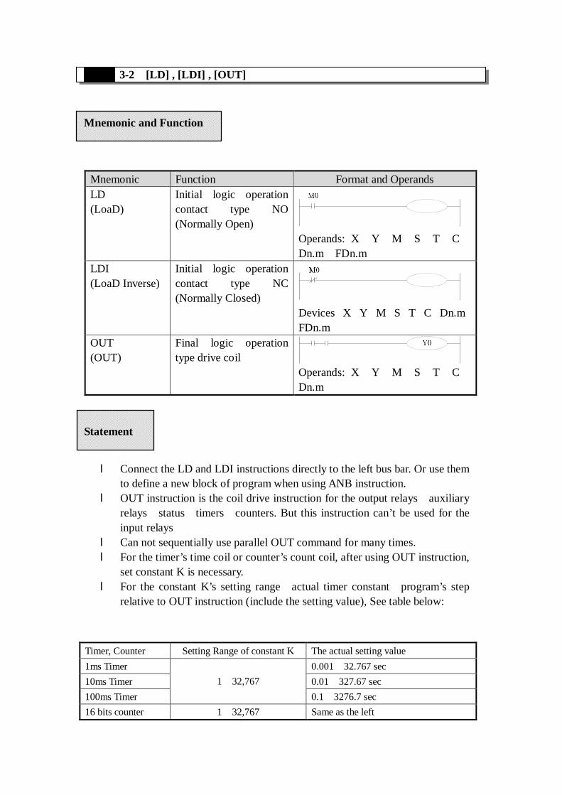
3-4.[OR] , [ORI]
Y6
M100
X5
X6
M11
Y6 M4 X7
M12
M13
Mnemonic Function Format and Operands
OR
(OR)
Parallel connection
of NO (Normally
Open) contacts
Operands: X、Y、M、S、T、C、Dn.m、FDn.m
ORI
(OR
Inverse)
Parallel connection
of NC (Normally
Closed) contacts
Operands: X、Y、M、S、T、C、Dn.m、FDn.m
Program
LD X2
AND M1
OUT Y2
LD Y2
ANI X3
OUT M2
AND T1
OUT Y3
Mnemonic and Function
Statements
Program
LD X5
OR X6
OR M11
OUT Y6
LDI Y6
AND M4
OR M12
ANI X7
OR M13
OUT M100
l Use the OR and ORI instructions for parallel connection of contacts. To connect a block
that contains more than one contact connected in series to another circuit block in parallel,
use an ORB instruction, which will be described later;
l OR and ORI start from the instruction’s step, parallel connect with the LD and LDI
instruction’s step said before. There is no limit for the parallel connect times.
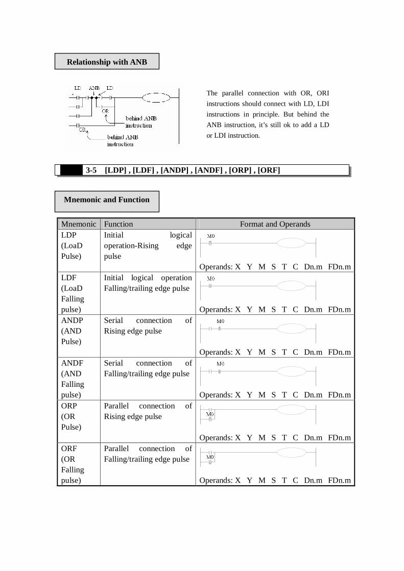
3-5.[LDP] , [LDF] , [ANDP] , [ANDF] , [ORP] , [ORF]
Mnemonic Function Format and Operands
LDP
(LoaD
Pulse)
Initial logical
operation-Rising edge
pulse
Operands: X、Y、M、S、T、C、Dn.m、FDn.m
LDF
(LoaD
Falling
pulse)
Initial logical operation
Falling/trailing edge pulse
Operands: X、Y、M、S、T、C、Dn.m、FDn.m
ANDP
(AND
Pulse)
Serial connection of
Rising edge pulse
Operands: X、Y、M、S、T、C、Dn.m、FDn.m
ANDF
(AND
Falling
pulse)
Serial connection of
Falling/trailing edge pulse
Operands: X、Y、M、S、T、C、Dn.m、FDn.m
ORP
(OR
Pulse)
Parallel connection of
Rising edge pulse
Operands: X、Y、M、S、T、C、Dn.m、FDn.m
ORF
(OR
Falling
pulse)
Parallel connection of
Falling/trailing edge pulse
Operands: X、Y、M、S、T、C、Dn.m、FDn.m
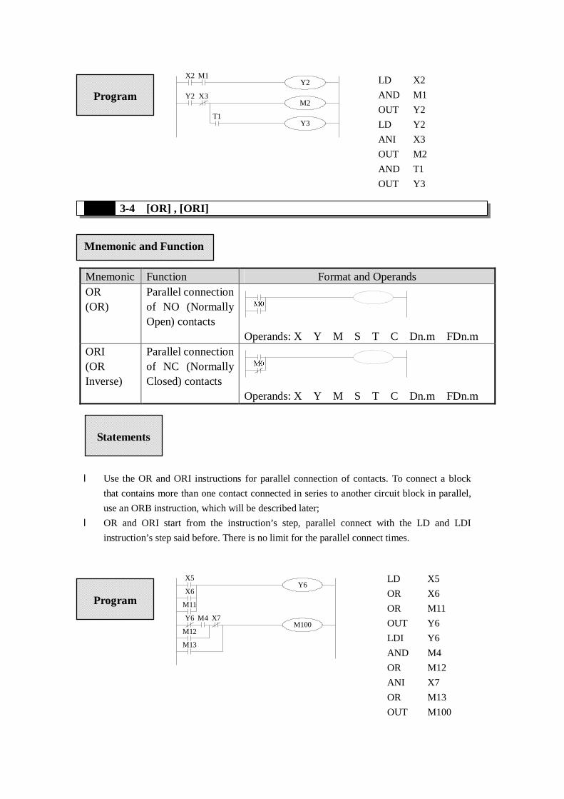
The parallel connection with OR, ORI
instructions should connect with LD, LDI
instructions in principle. But behind the
ANB instruction, it’s still ok to add a LD
or LDI instruction.
Relationship with ANB
Mnemonic and Function

3-6.[LDD] , [LDDI] , [ANDD] , [ANDDI] , [ORD] , [ORDI],[OUTD]
Mnemonic Function Format and Operands
LDD Read the status from the
contact directly
X0
D
Devices: X
LDDI Read the normally closed
contact directly
X0
D
Devices: X
ANDD Read the status from the
contact directly
X0
D
Devices: X
ANDDI Read the normally
closed contact directly
X0
D
Devices: X
ORD Read the status from the
contact directly X0
D
l LDP、ANDP、ORP are active for one program scan after the associated devices switch from
OFF to ON.
l LDF、ANDF、ORF are active for one program scan after the associated devices switch from
ON to OFF.
M13
M15
X5
X6
M8000 X7
LDP X5
ORP X6
OUT M13
LD M8000
ANDP X7
OUT M15
Statements
Program
Mnemonic and Function

l The function of LDD、ANDD、ORD instructions are similar with LD、AND、OR; LDDI、
ANDDI、ORDI instructions are similar with LDI、ANDI、ORI; but if the operand is X, the
LDD、ANDD、ORD commands read the signal from the terminals directly, this is the only
difference.
l OUTD and OUT are output instructions. But if use OUTD, output immediately if the
condition comes true, needn't wait the next scan cycle.
M13X0
X1
X2D
D
DY0D
3-7.[ORB]
Mnemonic Function Format and Devices
ORB
(OR Block)
Parallel connection
of multiply parallel
circuits
Devices: none
Devices: X
ORDI Read the normally
closed contact directly X0
D
Devices: X
OUTD Output to the contact
directly
Y0
D
Devices: Y
LDD X0
LDDI X2
ORD X2
ANB
OUTD Y0
Program
Statements
Mnemonic and Function
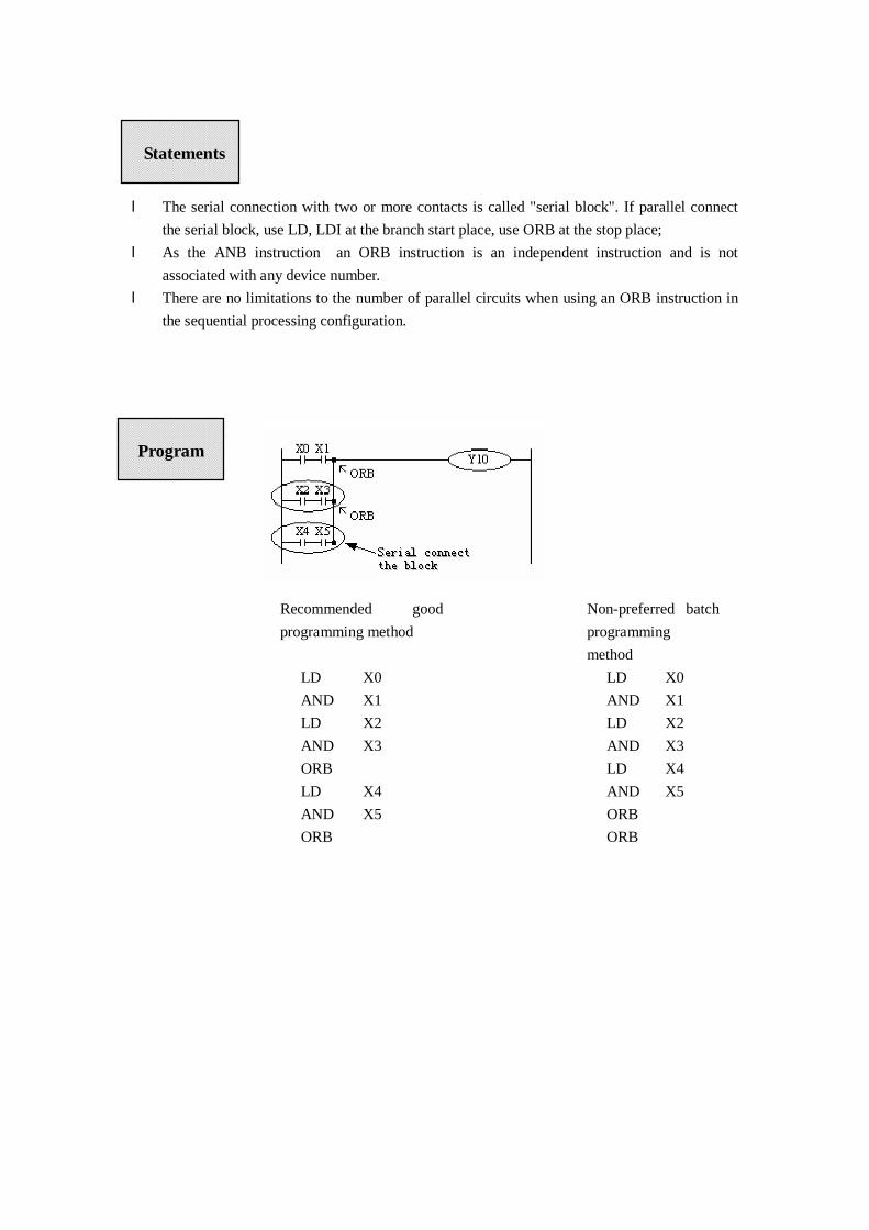
l The serial connection with two or more contacts is called "serial block". If parallel connect
the serial block, use LD, LDI at the branch start place, use ORB at the stop place;
l As the ANB instruction,an ORB instruction is an independent instruction and is not
associated with any device number.
l There are no limitations to the number of parallel circuits when using an ORB instruction in
the sequential processing configuration.
Recommended good
programming method:
LD X0
AND X1
LD X2
AND X3
ORB
LD X4
AND X5
ORB
Non-preferred batch
programming
method:
LD X0
AND X1
LD X2
AND X3
LD X4
AND X5
ORB
ORB
Statements
Program

3-8.[ANB]
Mnemonic Function Format and Devices
ANB
(And
Block)
Serial
connection of
multiply
parallel circuits
Devices: none
Start of a branch
End of a parallel circuit block
Serial connect with the preceding circuit
l To declare the starting point of the circuit block, use a LD or LDI
instruction. After completing the parallel circuit block, connect it to the
preceding block in series using the ANB instruction.
l It is possible to use as many ANB instructions as necessary to connect a
number of parallel circuit blocks to the preceding block in series.
LD X0
OR X1
LD X2
AND X3
LDI X4
AND X5
ORB
OR X6
ANB
OR X7
OUT Y20
Statements
Program
Mnemonic and Function
3-9.[MCS] , [MCR]
Mnemonic Function Format and Devices
MCS
(Master
control)
Denotes the
start of a
master control
block
Y0
Devices:None
MCR
(Master
control
Reset)
Denotes the
end of a master
control block
Y0
Devices:None
X1 X2
M2
M3M1
Y0
Y1
Y2
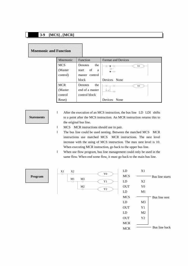
l After the execution of an MCS instruction, the bus line(LD、LDI)shifts
to a point after the MCS instruction. An MCR instruction returns this to
the original bus line.
l MCS、MCR instructions should use in pair.
l The bus line could be used nesting. Between the matched MCS、MCR
instructions use matched MCS、MCR instructions. The nest level
increase with the using of MCS instruction. The max nest level is 10.
When executing MCR instruction, go back to the upper bus line.
l When use flow program, bus line management could only be used in the
same flow. When end some flow, it must go back to the main bus line.
LD X1
MCS
LD X2
OUT Y0
LD M1
MCS
LD M3
OUT Y1
LD M2
OUT Y2
MCR
MCR
Bus line starts
Bus line nest
Bus line back
Statements
Program
Mnemonic and Function
3-10.[ALT]
Mnemonic Function Format and Devices
ALT
(Alternate
status)
The status of the
assigned devices
inverted on every
operation of the
instruction
M0ALT
Devices: Y、M、S、T、C、Dn.m
M0ALT
M0Y0
M100
Y1M0
3-11.[PLS] , [PLF]
Mnemonic Function Format and Devices
PLS
(Pulse)
Rising edge
pulse
Devices: Y、M、S、T、C、Dn.m
PLF
(Pulse
Falling)
Falling/trailing
edge pulse
Devices: Y、M、S、T、C、Dn.m
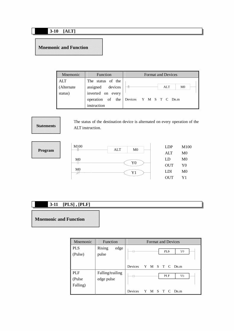
The status of the destination device is alternated on every operation of the
ALT instruction.
LDP M100
ALT M0
LD M0
OUT Y0
LDI M0
OUT Y1
Statements
Program
Mnemonic and Function
Mnemonic and Function

X0PLS M0
M0SET Y0
X1PLF M1
M1RST Y0
3-12.[SET] , [RST]
Mnemonic Function Format and Devices
SET(Set) Set a bit device
permanently
ON
Devices: Y、M、S、T、C、Dn.m
RST(Reset) Reset a bit
device
permanently
OFF
Devices: Y、M、S、T、C、Dn.m
l When a PLS instruction is executed, object devices Y and M operate
for one operation cycle after the drive input signal has turned ON.
l When a PLF instruction is executed, object devices Y and M operate
for one operation cycle after the drive input signal has turned OFF.
LD X0
PLS M0
LD M0
SET Y0
----------------------
LD X1
PLF M1
LD M1
RST Y0
Statements
Program
Mnemonic and Function

X10SET Y0
X11RST Y0
X12SET M50
X13RST M50
X14SET S0
X15RST S0
X10T250
K10
X17RST T250
X10
X11
Y0
LD X10
SET Y0
LD X11
RST Y0
LD X12
SET M50
LD X13
RST M50
LD X14
SET S0
LD X15
RST S0
LD X10
OUT T250 K10
LD X17
RST T250
l Turning ON X010 causes Y000 to turn ON. Y000 remains ON even after
X010 turns OFF. Turning ON X011 causes Y000 to turn OFF. Y000
remains OFF even after X011 turns OFF. It’s the same with M、S.
l SET and RST instructions can be used for the same device as many times
as necessary. However, the last instruction activated determines the
current status.
l Besides, it’s also possible to use RST instruction to reset the current
contents of timer, counter and contacts.
l When use SET, RST commands, avoid to use the same ID with OUT
command;
Statements
Program

3-13.【OUT】,【RST】for the counters
Mnemonic Function Format and Devices
OUT Final logic
operation type
coil drive
Device:K、D
RST Reset a bit device
permanently OFF
Device:C
C0 carries on increase count for the
OFF→ON of X011. When reach the
set value K10, output contact C0
activates. Afterwards, even X011 turns
from OFF to ON, counter’s current
value will not change, output contact
keep on activating.
To clear this, let X010 be the activate
status and reset the output contact. It’s
necessary to assign constant K or
indirect data register’s ID behind OUT
instruction.
l In the preceding example, when M0 is ON, carry on positive count with OFF→ON
of X0.
l Counter’s current value increase, when reach the set value (K or D), the output
contact is reset.
l When M1 is ON, counter’s C600 output contact is reset, counter’s current value turns
to be 0.
Programming of
interior counter
Programmi
ng of high
speed
Mnemonic and Function
Counter used for power cut retentive.
Even when power is cut, hold the current
value and output contact’s action status
and reset status.

3-14. [END]
Mnemonic Function Format and Devices:None
END
(END)
Force the
current
program scan
to end
Devices: None
When executing END instruction, refresh monitor timer. (Check if scan cycle is a long timer.)
PLC repeatedly carry on input disposal, program
executing and output disposal. If write END
instruction at the end of the program, then the
instructions behind END instruction won’t be
executed. If there’s no END instruction in the
program, the PLC executes the end step and then
repeat executing the program from step 0.
When debug, insert END in each program
segment to check out each program’s action.
Then, after confirm the correction of preceding
block’s action, delete END instruction.
Besides, the first execution of RUN begins with
END instruction.
Statements
Mnemonic and Function

3-15.[GROUP] , [GROUPE]
Mnemonic Function Format and Device
GROUP GROUP
Devices: None
GROUPE GROUP END
Devices: None
l GROUP and GROUPE should used in pairs.
l GROUP and GROUPE don't have practical meaning, they are used to optimize the program
structure. So, add or delete these instructions doesn't effect the program's running;
l The using method of GROUP and GROUPE is similar with flow instructions; enter GROUP
instruction at the beginning of group part; enter GROUPE instruction at the end of group
part.
Generally, GROUP and GROUPE
instruction can be programmed according to
the group's function. Meantime, the
programmed instructions can be FOLDED or
UNFOLDED. To a redundant project, these
two instructions are quite useful.
Statements
Mnemonic and Function

3-16.Items To Note When Programming
1、Contacts’ structure and step number
Even in the sequencial control circuit with the same action, it’s also available to
simple the program and save program’s steps according to the contacts’ structure.
General program principle is:a)write the circuit with many serial contacts on the top;
b)write the circuit with many parallel contacts in the left.
2、Program’s executing sequence
Handle the sequencial control program by【From top to bottom】and【From left to
right】
Sequencial control instructions also encode following this flow.
3、Dual output dual coil’s activation and the solution
l If carry on coil’s dual output (dual coil) in the sequencial control program, then
the backward action is prior.
l Dual output (dual coil) doesn’t go against the input rule at the program side. But
as the preceding action is very complicate, please modify the program as in the
following example.
Y0
Y0
X0 X2
X3 X4
Y0X0 X2
X3 X4
M0
M1
X0 X2
X3 X4
Y0M0
M1
There are other methods. E.g. jump instructions or step ladder. However, when use
step ladder, if the main program’s output coil is programmed, then the disposal
method is the same with dual coil, please note this.