Embed Size (px)
Citation preview
Managed by UT-Battellefor the Department of Energy
Basic Ring Beam Dynamics
ASAC 2008
Jeff Holmes
Sarah Cousineau

2 Managed by UT-Battellefor the Department of Energy
Outline
1) Brief description of ring lattice design.
2) Measurement of fundamental lattice parameters and test of linearity.
3) Identification and correction of cross-plane coupling in ring.
4) First ORBIT benchmarks of ring beam distributions.
5) Ring collimation studies.
3 Managed by UT-Battellefor the Department of Energy
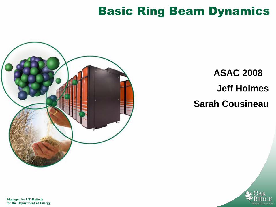
Ring Lattice Design and Working Point
• Lattice is a 4-fold symmetric
achromat.
• 6 Quadrupole power supply
families (4 in arc, 2 in straight)
• Nominal working tune is
(6.23, 6.20).
• Natural chromaticity is -7, -9.
• 4 sextupole families are
available for chromaticity
correction.
4 Managed by UT-Battellefor the Department of Energy
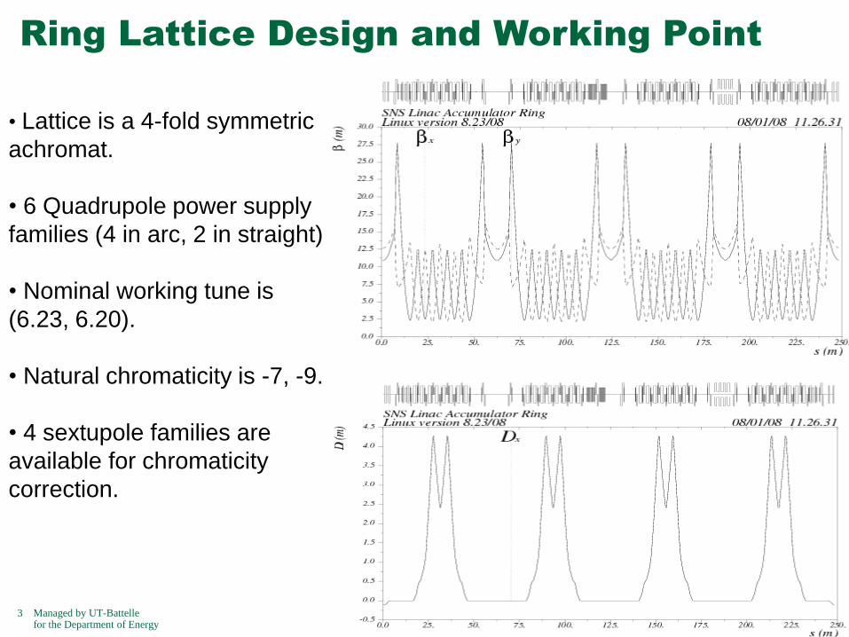
Measurement of Lattice Tune
• We routinely measure the tune using a single shot of turn-by-turn minipulse
BPM data.
• Recently we have been working at tune (6.27, 6.19).
Ring Turn-By-Turn BPM Data for Natural Chromaticity
Tune data

5 Managed by UT-Battellefor the Department of Energy
Measurement of Lattice Tune
We have measured both natural and corrected lattice chromaticity using:
= po/dp .
Natural chromaticity (Feb 01, 2006): x = -8, y = -7
Corrected chromaticity (Feb 12, 2006): x = -0.7, y = -0.25
Ring Turn-By-Turn BPM Data for Corrected Chromaticity

6 Managed by UT-Battellefor the Department of Energy
Lattice β Function Measurements – Tune
Method
• Measured average β for each of the 6 power supply families by changing
quadrupole strengths and measuring tune.
• Good agreement between measured/design was obtained, except for the
straight section vertical quadrupole family.
• This has not yet been corrected. Orbit response matrix analysis is ongoing.

7 Managed by UT-Battellefor the Department of Energy
Lattice β Measurements – Model Independent
Analysis
• Chromaticity-corrected BPM turn-by-turn data was used.
• Model Indepentent Analysis method determines β functions up to a constant
scale factor.
• Again, largest discrepancies are in vertical plane in straight sections.
0 50 100 150 200 2500
5
10
15
20
25
30
35
Ring Position (m)
Beta
function V
alu
es
MIA Determined Horizontal Betas
0 50 100 150 200 2500
2
4
6
8
10
12
14
16
Ring Position (m)
Beta
function V
alu
es
MIA Determined Vertical Betas
modelmeasured

8 Managed by UT-Battellefor the Department of Energy
Lattice Linearity Verification
• “Poor Man’s” phase space plots created from BPM turn-by-turn minipulse
data.
• Minipulse amplitude is varied from a minimum to the edge of the aperture
using the injection kickers.
All the way to the edge of the aperture, the lattice appears linear.
0.184
0.1818=2/11
0.184
Horizontal Vertical

9 Managed by UT-Battellefor the Department of Energy
Measurement of Transverse Coupling
We measure transverse coupling by injecting a single minipulse with a large vertical offset and small horizontal offset relative to the closed orbit.
BPM B04 - Horizontal
-8
-6
-4
-2
0
2
4
6
8
10
1 11 21 31 41 51 61 71 81 91
Turn number
Po
sit
ion
(m
m)
BPM B04 - Vertical
-20
-15
-10
-5
0
5
10
15
1 11 21 31 41 51 61 71 81 91
Turn number
Po
sit
ion
(m
m)

10 Managed by UT-Battellefor the Department of Energy
Correction of Ring Transverse Coupling
y = nw + f
C11 = amount of in-phase oscillations coupled in from
the vertical plane. |C11| ≤1.
C12 = amount of out-of-phase oscillations coupled in from
the vertical plane. |C12| ≤ 1.
yyyxxyx
yyxyxxx
ACCA
CCAA
y
x
yyy
yyy
cos)sincos(
)sincos(cos
1222
1211
Following formalism of D. Sagan & D. Rubin (e.g. PRSTAB 074001 (1999))

11 Managed by UT-Battellefor the Department of Energy
Results of Coupling Correction
Before correction After correction(6 vert. skew quadrupole
correctors set to 4.7 A)
-0.1
-0.05
0
0.05
0.1
0.15
0.2
0.25
1 3 5 7 9 11 13 15 17 19 21 23 25 27 29 31 33 35 37 39 41 43
BPM number
Co
up
lin
g c
oe
ff.
C11 A
C12 A
C11 B
C12 B
-0.06
-0.05
-0.04
-0.03
-0.02
-0.01
0
0.01
0.02
0.03
1 5 9 13 17 21 25 29 33 37 41
BPM numberC
ou
pli
ng
co
eff
.
C11
C12
Residual coupling is not a problem at this time

12 Managed by UT-Battellefor the Department of Energy
BPM Method for Measuring Real Space
Distributions
• For low intensities, in the absence of injection painting and decoherence, each
minipulse in a distribution follows an identical phase space path.
• We can measure a beam distribution “all at once”, as with wire scanners or harp, or
we can measure each piece separately with the BPMs and aggregate them at the
end.
• In the ring, we only need 1 turn-by-turn snapshot. In the RTBT, we vary the storage
time.
13 Managed by UT-Battellefor the Department of Energy
ORBIT Review and Status
ORBIT is a particle tracking parallel code for simulating rings and transport lines.
ORBIT has a broad range of simulation models…
• Real injection painting and distributions
• Linear and nonlinear symplectic tracking
• Transverse and longitudinal space charge – several models
• Transverse and longitudinal impedance
• Collimation and apertures
• Magnet errors
• 3D Field maps
• e-p simulations and feedback (talk by Danilov)
ORBIT Future:
ORBIT was used heavily in the design of the SNS ring.
Several successful ORBIT benchmark have been conducted for other machines (PSR,
CERN PSB).
We are starting to use ORBIT for SNS. Benchmarks are underway – e-p,
collimation, beam distributions…
Work is underway to translate ORBIT into python language, and invoke an
even more object-oriented approach.

14 Managed by UT-Battellefor the Department of Energy
First ORBIT Benchmarks in the Ring
• Experimental tune, injection were used. Nonlinear tracking (no chicane mults).
• To simulate experiment, we injected one mean-energy particle per turn.
• “Snake” structure seen in experiment and simulation likely due to tunes.
Benchmark Results
y (mm) y (mm)
x (
mm
)
At some BPMs the agreement is great! And at others it is not so great…
x (
mm
)

15 Managed by UT-Battellefor the Department of Energy
Ring Collimation Design
The ring collimators can take up to
2 kW of routine beam power, or two full
2 MW pulses.
The ring collimation system is a two-
stage system with 4 scrapers and 3
large collimators.
The scrapers are used to project the
beam into high emittance for high
efficiency absorption in downstream
collimator.
QH10, QV11scrapers
1st collimator 2nd collimator 3rdcollimator
QH12, QV13
Beam
16 Managed by UT-Battellefor the Department of Energy
General Collimation Observations
1. The collimators perform as the limiting aperture in the machine.
2. Beam loss due to collimation inefficiency is localized to the collimation
straight section and the beginning of the downstream arc.
3. Areas where beam loss is higher than anticipated are:
a) The quadrupole doublet between the primary and secondary
collimators
b) The first quadrupole and dipole in the downstream arc. This is likely
due to single stage collimation inefficiency
4. ORBIT collimation benchmarks are in reasonable agreement, to within
the conversion accuracy of BLM signals to Joules of beam loss
(Cousineau, PAC2007).
17 Managed by UT-Battellefor the Department of Energy
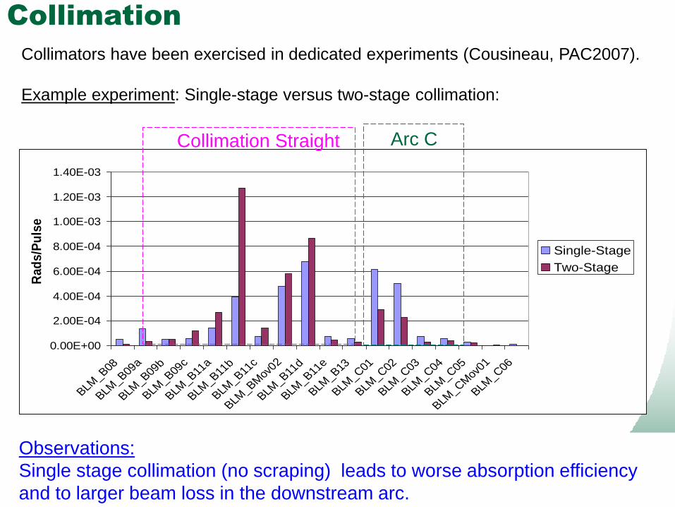
Collimation
0.00E+00
2.00E-04
4.00E-04
6.00E-04
8.00E-04
1.00E-03
1.20E-03
1.40E-03
BLM_B08
BLM_B09
a
BLM_B09
b
BLM_B09
c
BLM_B11
a
BLM_B11
b
BLM_B11
c
BLM_BM
ov02
BLM_B11
d
BLM_B11
e
BLM_B13
BLM_C
01
BLM_C
02
BLM_C
03
BLM_C
04
BLM_C
05
BLM_C
Mov
01
BLM_C
06
Ra
ds
/Pu
lse
Single-Stage
Two-Stage
Collimation Straight
Observations:
Single stage collimation (no scraping) leads to worse absorption efficiency
and to larger beam loss in the downstream arc.
Arc C
Collimators have been exercised in dedicated experiments (Cousineau, PAC2007).
Example experiment: Single-stage versus two-stage collimation:

18 Managed by UT-Battellefor the Department of Energy
Summary
We have measured the lattice parameters and found reasonable agreement with the model.
We have measured and fixed cross-plane coupling in the ring.
We have begun ORBIT benchmarks of ring beam distributions at low intensity.
We have begun to characterize the collimation system peformance.