Embed Size (px)
Citation preview

1
Table of Contents
Introduction ..............................................................................2
Electron Theory........................................................................4
Conductors, Insulators and Semiconductors.........................5
Electric Charges .......................................................................7
Current ......................................................................................9
Voltage ....................................................................................11
Resistance ..............................................................................13
Simple Electric Circuit ...........................................................15
Ohms Law..............................................................................16
DC Series Circuit ....................................................................18
DC Parallel Circuit ..................................................................23
Series-Parallel Circuits ...........................................................30
Power ......................................................................................34
Magnetism .............................................................................37
Electromagnetism ..................................................................39
Introduction to AC .................................................................42
AC Generators ........................................................................44
Frequency...............................................................................47
Voltage and Current ...............................................................48
Inductance ..............................................................................51
Capacitance ............................................................................56
Inductive and Capacitive Reactance .....................................61
Series R-L-C Circuit ................................................................67
Parallel R-L-C Circuit ..............................................................69
Power and Power Factor in an AC Circuit .............................71
Transformers ..........................................................................75
Three-Phase Transformers ....................................................80
Review Answers ....................................................................83
Final Exam ..............................................................................84

2
Welcome to the first course in the STEP 2000 series,Siemens Technical Education Program designed to prepareour distributors for the year 2000 and beyond. This coursecovers Basics of Electricity and is designed to prepare youfor subsequent courses on Siemens Energy & Automationproducts.
Upon completion of Basics of Electricity you will be able to:
Explain the difference between conductors andinsulators
Use Ohms Law to calculate current, voltage, andresistance
Calculate equivalent resistance for series, parallel, orseries-parallel circuits
Calculate voltage drop across a resistor
Calculate power given other basic values
Identify factors that determine the strength and polarityof a current-carrying coils magnetic field
Determine peak, instantaneous, and effective values ofan AC sine wave
Identify factors that effect inductive reactance and ca-pacitive reactance in an AC circuit
Calculate total impedance of an AC circuit
Explain the difference between real power and apparentpower in an AC circuit
Introduction

3
Calculate primary and secondary voltages of single-phase and three-phase transformers
Calculate kVA of a transformer
The objectives listed above may sound strange to you. Youmay also wonder why you would need to know these thingsto sell Siemens Energy & Automation products. Developing abasic knowledge of electrical concepts, however, will helpyou to better understand customer applications. In addition,you will be better able to describe products to customers anddetermine important differences between products.
If you are an employee of a Siemens Energy & Automationauthorized distributor, fill out the final exam tear-out card andmail in the card. We will mail you a certificate of completion ifyou score a passing grade. Good luck with your efforts.

4
Elements of an atom
Electron Theory
All matter is composed of molecules which are made up of acombination of atoms. Atoms have a nucleus with electronsorbiting around it. The nucleus is composed of protons andneutrons (not shown). Most atoms have an equal number ofelectrons and protons. Electrons have a negative charge (-).Protons have a positive charge (+). Neutrons are neutral. Thenegative charge of the electrons is balanced by the positivecharge of the protons. Electrons are bound in their orbit bythe attraction of the protons. These are referred to as boundelectrons.
Electrons in the outer band can become free of their orbit bythe application of some external force such as movementthrough a magnetic field, friction, or chemical action. Theseare referred to as free electrons. A free electron leaves a voidwhich can be filled by an electron forced out of orbit fromanother atom. As free electrons move from one atom to thenext an electron flow is produced. This is the basis ofelectricity.
Free electrons
5
Conductors
Conductors, Insulators and Semiconductors
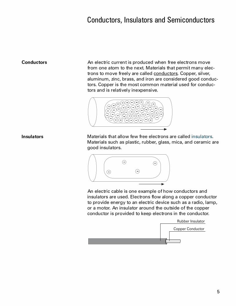
An electric current is produced when free electrons movefrom one atom to the next. Materials that permit many elec-trons to move freely are called conductors. Copper, silver,aluminum, zinc, brass, and iron are considered good conduc-tors. Copper is the most common material used for conduc-tors and is relatively inexpensive.
Materials that allow few free electrons are called insulators.Materials such as plastic, rubber, glass, mica, and ceramic aregood insulators.
An electric cable is one example of how conductors andinsulators are used. Electrons flow along a copper conductorto provide energy to an electric device such as a radio, lamp,or a motor. An insulator around the outside of the copperconductor is provided to keep electrons in the conductor.
Insulators

6
Semiconductor materials, such as silicon, can be used tomanufacture devices that have characteristics of bothconductors and insulators. Many semiconductor devices willact like a conductor when an external force is applied in onedirection. When the external force is applied in the oppositedirection, the semiconductor device will act like an insulator.This principle is the basis for transistors, diodes, and othersolid-state electronic device.
1. List the three basic elements of an atom and statethe charge of each (positive, negative, or neutral).
Element Charge____________ ____________
____________ ____________
____________ ____________
2. An electron forced out of orbit by an external force iscalled a ____________ ____________ .
3. Conductors allow ____________ free electrons to flowwhen an external electric force is applied.
4. Which of the following materials are goodconductors?
a. copper e. aluminumb. plastic f. glassc. silver g. irond. rubber h. mica
5. Semiconductor devices can be manufactured toallow ____________ electrons to flow in one directionand ____________ electrons to flow in the oppositedirection.
Semiconductors
Review 1

7
Elements are often identified by the number of electrons inorbit around the nucleus of the atoms making up the elementand by the number of protons in the nucleus. A hydrogenatom, for example, has only one electron and one proton. Analuminum atom (illustrated) has 13 electrons and 13 protons.An atom with an equal number of electrons and protons issaid to be electrically neutral.
Electrons in the outer band of an atom are easily displaced bythe application of some external force. Electrons which areforced out of their orbits can result in a lack of electronswhere they leave and an excess of electrons where theycome to rest. The lack of electrons is called a positive chargebecause there are more protons than electrons. The excess ofelectrons has a negative charge. A positive or negativecharge is caused by an absence or excess of electrons. Thenumber of protons remains constant.
Neutral state of an atom
Electric Charges
Positive and negativecharges

8
Attraction and repulsion ofelectric charges
The old saying, opposites attract, is true when dealing withelectric charges. Charged bodies have an invisible electricfield around them. When two like-charged bodies arebrought together, their electric field will work to repel them.When two unlike-charged bodies are brought together, theirelectric field will work to attract them. The electric fieldaround a charged body is represented by invisible lines offorce. The invisible lines of force represent an invisible elec-trical field that causes the attraction and repulsion. Lines offorce are shown leaving a body with a positive charge andentering a body with a negative charge.
During the 18th century a French scientist, Charles A.Coulomb, studied fields of force that surround chargedbodies. Coulomb discovered that charged bodies attract orrepel each other with a force that is directly proportional tothe product of the charges, and inversely proportional to thesquare of the distance between them. Today we call thisCoulombs Law of Charges. Simply put, the force ofattraction or repulsion depends on the strength of thecharged bodies, and the distance between them.
Coulombs Law
9
Current
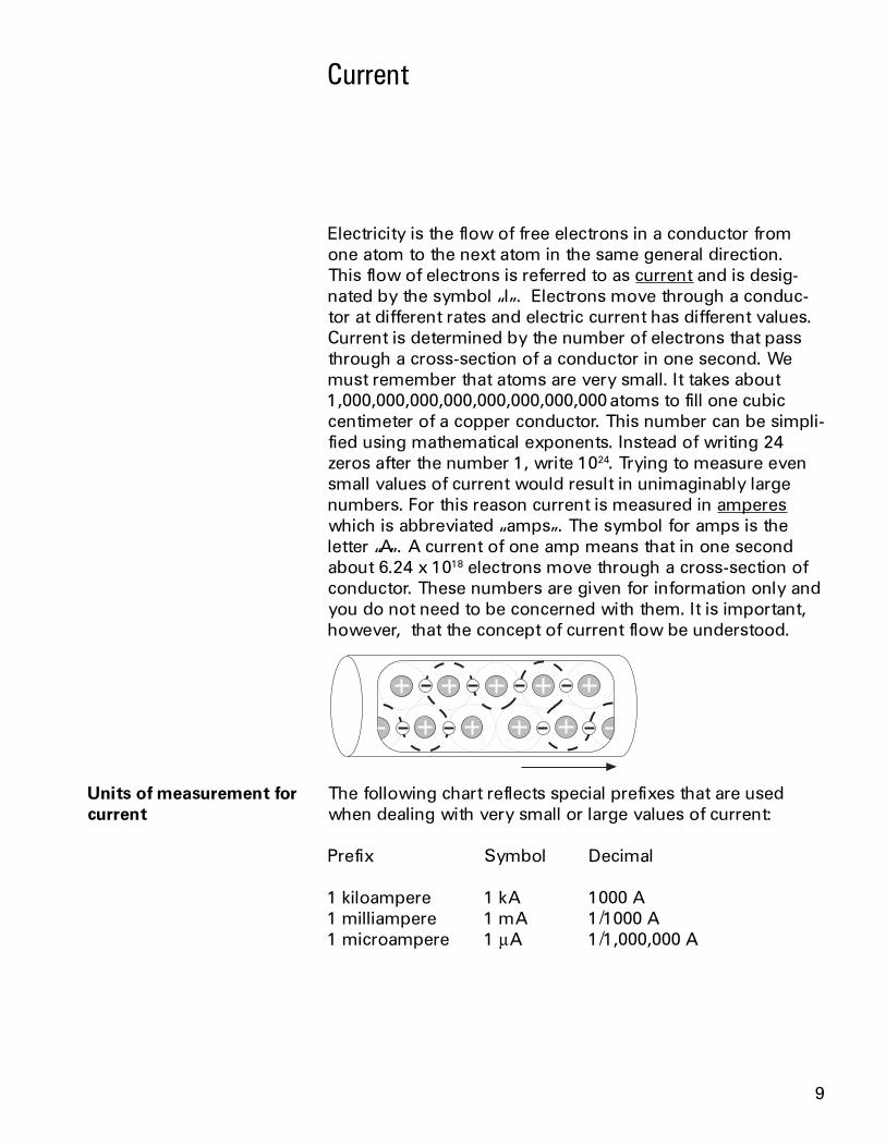
Electricity is the flow of free electrons in a conductor fromone atom to the next atom in the same general direction.This flow of electrons is referred to as current and is desig-nated by the symbol I. Electrons move through a conduc-tor at different rates and electric current has different values.Current is determined by the number of electrons that passthrough a cross-section of a conductor in one second. Wemust remember that atoms are very small. It takes about1,000,000,000,000,000,000,000,000 atoms to fill one cubiccentimeter of a copper conductor. This number can be simpli-fied using mathematical exponents. Instead of writing 24zeros after the number 1, write 1024. Trying to measure evensmall values of current would result in unimaginably largenumbers. For this reason current is measured in ampereswhich is abbreviated amps. The symbol for amps is theletter A. A current of one amp means that in one secondabout 6.24 x 10¹⁸ electrons move through a cross-section ofconductor. These numbers are given for information only andyou do not need to be concerned with them. It is important,however, that the concept of current flow be understood.
The following chart reflects special prefixes that are usedwhen dealing with very small or large values of current:
Prefix Symbol Decimal
1 kiloampere 1 kA 1000 A1 milliampere 1 mA 1/1000 A1 microampere 1 mA 1/1,000,000 A
Units of measurement forcurrent

10
Direction of current flow Some authorities distinguish between electron flow andcurrent flow. Conventional current flow theory ignores theflow of electrons and states that current flows from positiveto negative. To avoid confusion, this book will use theelectron flow concept which states that electrons flow fromnegative to positive.

11
Electricity can be compared with water flowing through apipe. A force is required to get water to flow through a pipe.This force comes from either a water pump or gravity.Voltage is the force that is applied to a conductor thatcauses electric current to flow.
Electrons are negative and are attracted by positive charges.They will always be attracted from a source having an excessof electrons, thus having a negative charge, to a sourcehaving a deficiency of electrons which has a positive charge.The force required to make electricity flow through a conduc-tor is called a difference in potential, electromotive force(emf), or more simply referred to as voltage. Voltage is desig-nated by the letter E, or the letter V. The unit of measure-ment for voltage is volts which is designated by the letter V.
Voltage
12
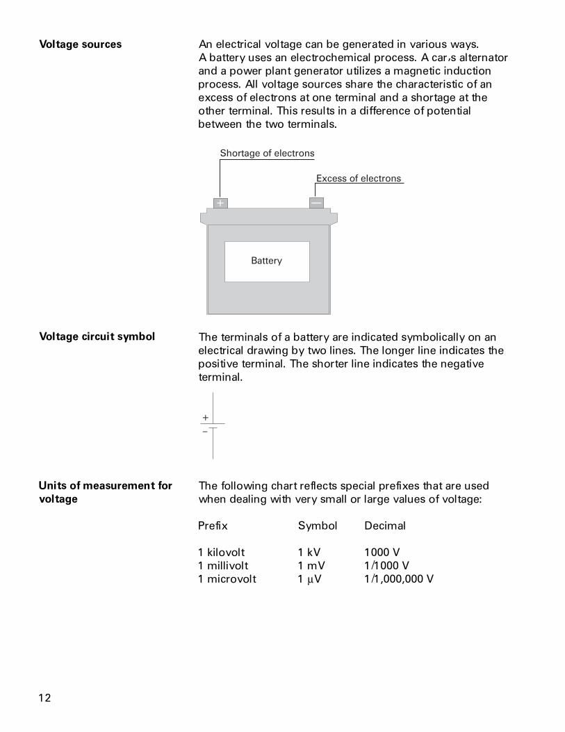
Voltage sources An electrical voltage can be generated in various ways.A battery uses an electrochemical process. A cars alternatorand a power plant generator utilizes a magnetic inductionprocess. All voltage sources share the characteristic of anexcess of electrons at one terminal and a shortage at theother terminal. This results in a difference of potentialbetween the two terminals.
The terminals of a battery are indicated symbolically on anelectrical drawing by two lines. The longer line indicates thepositive terminal. The shorter line indicates the negativeterminal.
The following chart reflects special prefixes that are usedwhen dealing with very small or large values of voltage:
Prefix Symbol Decimal
1 kilovolt 1 kV 1000 V1 millivolt 1 mV 1/1000 V1 microvolt 1 mV 1/1,000,000 V
Voltage circuit symbol
Units of measurement forvoltage

13
A third factor that plays a role in an electrical circuit isresistance. All material impedes the flow of electrical currentto some extent. The amount of resistance depends uponcomposition, length, cross-section and temperature of theresistive material. As a rule of thumb, resistance of a conduc-tor increases with an increase of length or a decrease ofcross-section. Resistance is designated by the symbol R.The unit of measurement for resistance is ohms (W).
Resistance is usually indicated symbolically on an electricaldrawing by one of two ways. An unfilled rectangle is com-monly used. A zigzag line may also be used.
Resistance can be in the form of various components.A resistor may be placed in the circuit, or the circuit mightcontain other devices that have resistance.
The following chart reflects special prefixes that are com-monly used when dealing with values of resistance:
Prefix Symbol Decimal
1 kilohm 1 kW 1000 W1 megohm 1 MW 1,000,000 W
Resistance
Resistance circuit symbols
Units of measurement forresistance

14
1. Elements are identified by the number of____________ in orbit around the nucleus.
2. A material that has an excess of electrons is said tohave a ____________ charge.
3. A material that has a deficiency of electrons is saidto have a ____________ charge.
4. Like charges ____________ and unlike charges____________ .
5. The force that is applied to a conductor to causecurrent flow is ____________ .
6. Electrons move from
a. positive to negativeb. negative to positive
7. With an increase of length or a decrease of cross-section of a conductor, resistance will
a. increaseb. decrease
Review 2
15
Simple Electric Circuit
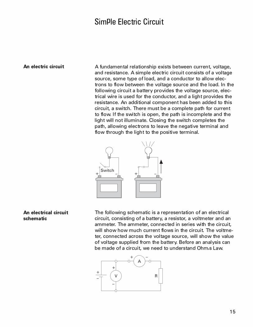
A fundamental relationship exists between current, voltage,and resistance. A simple electric circuit consists of a voltagesource, some type of load, and a conductor to allow elec-trons to flow between the voltage source and the load. In thefollowing circuit a battery provides the voltage source, elec-trical wire is used for the conductor, and a light provides theresistance. An additional component has been added to thiscircuit, a switch. There must be a complete path for currentto flow. If the switch is open, the path is incomplete and thelight will not illuminate. Closing the switch completes thepath, allowing electrons to leave the negative terminal andflow through the light to the positive terminal.
The following schematic is a representation of an electricalcircuit, consisting of a battery, a resistor, a voltmeter and anammeter. The ammeter, connected in series with the circuit,will show how much current flows in the circuit. The voltme-ter, connected across the voltage source, will show the valueof voltage supplied from the battery. Before an analysis canbe made of a circuit, we need to understand Ohms Law.
An electric circuit
An electrical circuitschematic
16
Ohms Law
George Simon Ohm andOhms Law
The relationship between current, voltage and resistancewas studied by the 19th century German mathematician,George Simon Ohm. Ohm formulated a law which states thatcurrent varies directly with voltage and inversely with resis-tance. From this law the following formula is derived:
I ER
= = or CurrentVoltage
Resistance
Ohms Law is the basic formula used in all electrical circuits.Electrical designers must decide how much voltage isneeded for a given load, such as computers, clocks, lampsand motors. Decisions must be made concerning the rela-tionship of current, voltage and resistance. All electricaldesign and analysis begins with Ohms Law. There are threemathematical ways to express Ohms Law. Which of theformulas is used depends on what facts are known beforestarting and what facts need to be known.
I ER
E I R R EI
= = × =
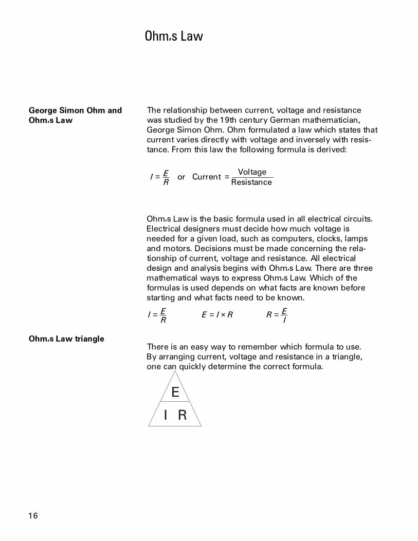
There is an easy way to remember which formula to use.By arranging current, voltage and resistance in a triangle,one can quickly determine the correct formula.
Ohms Law triangle

17
To use the triangle, cover the value you want to calculate.The remaining letters make up the formula.
R EI
=E I R= ×I ER
=
Using the triangle
Ohms Law can only give the correct answer when the correctvalues are used. Remember the following three rules:
Current is always expressed in Amperes or Amps Voltage is always expressed in Volts Resistance is always expressed in Ohms
Using the simple circuit below, assume that the voltage sup-plied by the battery is 10 volts, and the resistance is 5 W.
To find how much current is flowing through the circuit, coverthe I in the triangle and use the resulting equation.
I ER
I I= → = → = volts
amps105
2Ω
Using the same circuit, assume the ammeter reads 200 mAand the resistance is known to be 10 W. To solve for voltage,cover the E in the triangle and use the resulting equation.
E I R E E olts= × → = × → = . v2 10 2
Remember to use the correct decimal equivalent when deal-ing with numbers that are preceded with milli (m), micro (m)or kilo (k). In this example had 200 been used instead ofconverting the value to .2, the wrong answer of 2000 voltswould have been calculated.
Examples of solvingOhms Law

18
DC Series Circuit
A series circuit is formed when any number of resistors areconnected end-to-end so that there is only one path forcurrent to flow. The resistors can be actual resistors or otherdevices that have resistance. The illustration shows fourresistors connected end-to-end. There is one path of currentflow from the negative terminal of the battery through R4, R3,R2, R1 returning to the positive terminal.
The values of resistance add in a series circuit. If a 4 W resis-tor is placed in series with a 6 W resistor, the total value willbe 10 W. This is true when other types of resistive devices areplaced in series. The mathematical formula for resistance inseries is:
Rt R R R R= + + +1 2 3 4
Ω Ω Ω Ω Ω
Given a series circuit where R1 is 11 KW, R2 is 2 KW, R3is 2 KW, R4 is 100 W, and R5 is 1 KW, what is the totalresistance?
Rt R R R R
Rt
Rt
= + + += + + + +=
1 2 3 4
11 000 2 000 2 000 100 1 000
16 100
+R5
, , , ,, Ω
Resistance in a seriescircuit
Formula for seriesresistance
19
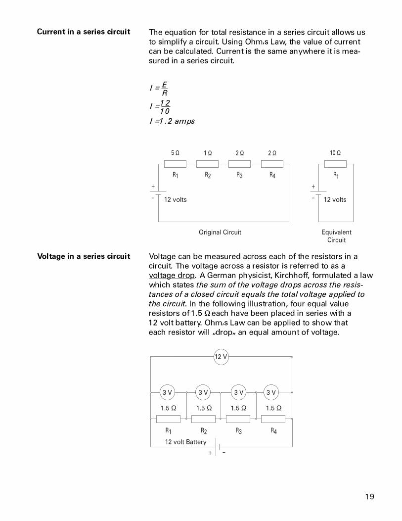
The equation for total resistance in a series circuit allows usto simplify a circuit. Using Ohms Law, the value of currentcan be calculated. Current is the same anywhere it is mea-sured in a series circuit.
I ER
I
I amps
=
=
=
1210
1 2.
Ω Ω Ω Ω Ω
Voltage can be measured across each of the resistors in acircuit. The voltage across a resistor is referred to as avoltage drop. A German physicist, Kirchhoff, formulated a lawwhich states the sum of the voltage drops across the resis-
tances of a closed circuit equals the total voltage applied to
the circuit. In the following illustration, four equal valueresistors of 1.5 Weach have been placed in series with a12 volt battery. Ohms Law can be applied to show thateach resistor will drop an equal amount of voltage.
Ω Ω ΩΩ
Current in a series circuit
Voltage in a series circuit

20
First, solve for total resistance:
Rt R R R R
Rt
Rt
= + + += + + +=
1 2 3 4
1 5 1 5 1 5 1 5
6
. . . .
Ω
Second, solve for current:
I ER
I
I amps
=
=
=
126
2
Third, solve for voltage across any resistor:
E I R
E
E volts
= ×= ×=
2 1 5
3
.
If voltage were measured across any single resistor, themeter would read three volts. If voltage were read across acombination of R3 and R4 the meter would read six volts. Ifvoltage were read across a combination of R2, R3, and R4the meter would read nine volts. If the voltage drops of allfour resistors were added together the sum would be12 volts, the original supply voltage of the battery.
It is often desirable to use a voltage potential that is lowerthan the supply voltage. To do this, a voltage divider, similarto the one illustrated, can be used. The battery representsEin which in this case is 50 volts. The desired voltage isrepresented by Eout which mathematically works out tobe 40 volts. To calculate this voltage, first solve for totalresistance.
Rt R R
Rt
Rt
= += +=
1 2
5 20
25 Ω
Voltage division in aseries circuit

21
Second, solve for current:
IE inRt
I
I amps
=
=
=
5025
2
Finally, solve for voltage:
Eout I R
Eout
Eout volts
= ×= ×=
2
2 20
40
Ω
Ω

22
1. The basic Ohms Law formula is ____________ .
2. When solving circuit problems; current must alwaysbe expressed in ____________ , voltage must alwaysbe expressed in ____________ and resistance mustalways be expressed in ____________ .
3. The total current of a simple circuit with a voltagesupply of 12 volts and a resistance of 24 Wis ____________ amps.
4. What is the total resistance of a series circuit withthe following values: R1=10 W, R2=15 W, andR3=20 W? ____________ W.
5. What is total current of a series circuit that has a 120volt supply and 60 W resistance?
6. In the following circuit the voltage dropped acrossR1 is ____________ volts and R2 is ____________
Ω Ω
7. In the following circuit voltage dropped across R1 is____________ volts, and R2 is ____________ volts.
Ω Ω
Review 3

23
Resistance in a parallelcircuit
A parallel circuit is formed when two or more resistances areplaced in a circuit side-by-side so that current can flowthrough more than one path. The illustration shows tworesistors placed side-by-side. There are two paths of currentflow. One path is from the negative terminal of the batterythrough R1 returning to the positive terminal. The secondpath is from the negative terminal of the battery throughR2 returning to the positive terminal of the battery.
To determine the total resistance when resistors are of equalvalue in a parallel circuit, use the following formula:
Rt = Value of any one resistor
Number of resistors
In the following illustration there are three 15 W resistors.The total resistance is:
Rt
Rt
Rt
=
=
=
Value of any one resistor
Number of resistors
153
5 Ω
Ω Ω Ω
Formula for equalvalue resistors in aparallel circuit
DC Parallel Circuit

24
Formula for unequalresistors in a parallel circuit
There are two formulas to determine total resistance forunequal value resistors in a parallel circuit. The first formula isused when there are three or more resistors. The formula canbe extended for any number of resistors.
1 1
1
1
2
1
3Rt R R R= + +
In the following illustration there are three resistors, each ofdifferent value. The total resistance is:
1 1
1
1
2
1
3
1 1
5
1
10
1
20
1 4
20
2
20
1
20
1 7
20
1
20
7
2 86
Rt R R R
RtInsert value of the resistors
RtFind lowest common
RtAdd the numerators
Rt Invert both sides of the equation
Rt Divide
= + +
= + +
= + +
=
=
=
denominator
. Ω
Ω Ω Ω

25
The second formula is used when there are only tworesistors.
RtR R
R R= ×
+1 2
1 2
In the following illustration there are two resistors, each ofdifferent value. The total resistance is:
RtR R
R R
Rt
Rt
Rt
= ×+
= ×+
=
=
1 2
1 2
5 10
5 10
50
15
3 33. Ω
Ω Ω
When resistors are placed in parallel across a voltage source,the voltage is the same across each resistor. In the followingillustration three resistors are placed in parallel across a12 volt battery. Each resistor has 12 volts available to it.
Voltage in a parallel circuit

26
Current in a parallel circuit Current flowing through a parallel circuit divides and flowsthrough each branch of the circuit.
Total current in a parallel circuit is equal to the sum of thecurrent in each branch. The following formula applies tocurrent in a parallel circuit:
It I I I= + +1 2 3
When equal resistances are placed in a parallel circuit,opposition to current flow is the same in each branch. Inthe following circuit R1 and R2 are of equal value. If totalcurrent (It) is 10 amps, then 5 amps would flow through R1and 5 amps would flow through R2.
It I I
It amps amps
It amps
= += +=
1 2
5 5
10
Current flow with equalvalue resistors in a parallelcircuit

27
Current flow with unequalvalue resistors in a parallelcircuit
When unequal value resistors are placed in a parallel circuit,opposition to current flow is not the same in every circuitbranch. Current is greater through the path of least resis-tance. In the following circuit R1 is 40 W and R2 is 20 W.Small values of resistance means less opposition to currentflow. More current will flow through R2 than R1.
Ω Ω
Using Ohms Law, the total current for each circuit can becalculated.
I ER
I
I
I ER
I
I
I I
It amps amps
It amps
11
112
40
1 3
22
212
20
2 6
1 2
3 6
9
=
=
=
=
=
=
= += +=
volts
amps
volts
amps
It
Ω
Ω
.
.
. .
.

28
Total current can also be calculated by first calculating totalresistance, then applying the formula for Ohms Law.
RtR R
R R
Rt
Rt
Rt
= ×+
= ×+
=
=
1 2
1 2
40 20
40 20
800
60
13 333
Ω ΩΩ Ω
ΩΩ
Ω.
ItE
Rt
It
It
=
=
=
12
13 333
9
volts
amps
..
Ω

29
1. The total resistance of a parallel circuit that has four20 W resistors is ____________ W.
2. Rt for the following circuit is ____________ W.
Ω Ω Ω
3. Rt for the following circuit is ____________ W.
Ω Ω
4. Voltage available at R2 in the following circuit is____________ volts.
Ω Ω
5. In a parallel circuit with two resistors of equal valueand a total current flow of 12 amps, the value ofcurrent through each resistor is ____________ amps.
6. In the following circuit current flow through R1 is____________ amps, and R2 is ____________ amps.
Ω Ω
Review 4

30
Series-Parallel Circuits
Series-parallel circuits are also known as compound circuits.At least three resistors are required to form a series-parallelcircuit. The following illustrations show two ways a series-parallel combination could be found.
The formulas required for solving current, voltage and resis-tance problems have already been defined. To solve a series-parallel circuit, reduce the compound circuits to equivalentsimple circuits. In the following illustration R1 and R2 areparallel with each other. R3 is in series with the parallel circuitof R1 and R2.
Ω
Ω
Ω
Simplifying a series-parallelcircuit to a series circuit

31
First, use the formula to determine total resistance of a paral-lel circuit to find the total resistance of R1 and R2. When theresistors in a parallel circuit are equal, the following formula isused:
R
R
R
=
=
=
Value of any one resistor
Number of resistors
10
2
5
Ω
Ω
Second, redraw the circuit showing the equivalent values.The result is a simple series circuit which uses alreadylearned equations and methods of problem solving.
Ω Ω
In the following illustration R1 and R2 are in series with eachother. R3 is in parallel with the series circuit of R1 and R2.
Ω
Ω
Ω
First, use the formula to determine total resistance of a seriescircuit to find the total resistance of R1 and R2. The followingformula is used:
R R R
R
R
= += +=
1 2
10 10
20
Ω ΩΩ
Simplifying aseries-parallel circuitto a parallel circuit

32
Second, redraw the circuit showing the equivalent values.The result is a simple parallel circuit which uses alreadylearned equations and methods of problem solving.
Ω Ω
Ω

33
1. Calculate equivalent resistance for R1 and R2 andtotal resistance for the entire circuit.
Ω
Ω
Ω
R1/R2 equivalent resistance = ____________ W
Total resistance = ____________ W
2. Calculate equivalent resistance for R1 and R2 andtotal resistance for the entire circuit.
Ω
Ω
Ω
R1/R2 equivalent resistance = ____________ W
Total resistance = ____________ W
Review 5
34
Power
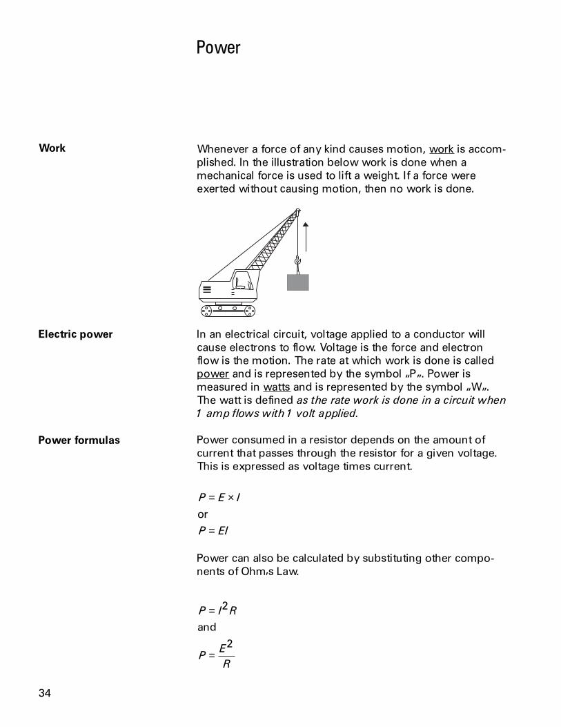
Whenever a force of any kind causes motion, work is accom-plished. In the illustration below work is done when amechanical force is used to lift a weight. If a force wereexerted without causing motion, then no work is done.
In an electrical circuit, voltage applied to a conductor willcause electrons to flow. Voltage is the force and electronflow is the motion. The rate at which work is done is calledpower and is represented by the symbol P. Power ismeasured in watts and is represented by the symbol W.The watt is defined as the rate work is done in a circuit when
1 amp flows with 1 volt applied.
Power consumed in a resistor depends on the amount ofcurrent that passes through the resistor for a given voltage.This is expressed as voltage times current.
P E I
P EI
= ×
=or
Power can also be calculated by substituting other compo-nents of Ohms Law.
P I R
PE
R
=
=
2
2
and
Work
Electric power
Power formulas
35
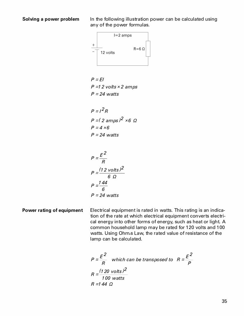
In the following illustration power can be calculated usingany of the power formulas.
Ω
P EI
P amps
P
== ×=
12 2
24
volts
watts
P I R
P
P
P
=
= ×= ×=
2
2 6
4 6
24
( amps )2
watts
Ω
PE
R
P
P
P
=
=
=
=
2
12 2
6
144
6
24
( volts )
watts
Ω
Electrical equipment is rated in watts. This rating is an indica-tion of the rate at which electrical equipment converts electri-cal energy into other forms of energy, such as heat or light. Acommon household lamp may be rated for 120 volts and 100watts. Using Ohms Law, the rated value of resistance of thelamp can be calculated.
PE
RR
E
P
R
R
= =
=
=
2 2
120 2
100
144
which can be transposed to
volts )
watts
(
Ω
Solving a power problem
Power rating of equipment

36
Using the basic Ohms Law formula, the amount of currentflow for the 120 volt, 100 watt lamp can be calculated.
IE
R
I
I amps
=
=
=
120
144
833
volts
Ω.
A lamp rated for 120 volts and 75 watts has a resistance of192 W and a current of .625 amps would flow if the lamp hadthe rated voltage applied to it.
RE
P
R
R
=
=
=
2
120 2
192
( volts )
75 watts
Ω
IE
R
I
I amps
=
=
=
120
192
625
volts
Ω.
It can be seen that the 100 watt lamp converts energy fasterthan the 75 watt lamp. The 100 watt lamp will give off morelight and heat.
Current flow through a resistive material causes heat. Anelectrical component can be damaged if the temperature istoo high. For this reason, electrical equipment is often ratedfor a maximum wattage. The higher the wattage rating, themore heat the equipment can dissipate.
Heat

37
Magnetism
The principles of magnetism are an intregal part of electricity.Electromagnets are used in some direct current circuits.Alternating current cannot be understood without first under-standing magnetism.
The three most common forms of magnets are the horse-shoe, bar and compass needle.
All magnets have two characteristics. They attract and holdiron. If free to move, like the compass needle, the magnet willassume roughly a north-south position.
Every magnet has two poles, one north pole and one southpole. This is the point at which maximum attraction occurs.Invisible magnetic lines of flux leave the north pole and enterthe south pole. While the lines of flux are invisible, the effectsof magnetic fields can be made visible. When a sheet ofpaper is placed on a magnet and iron filings loosely scatteredover it, the filings will arrange themselves along the invisiblelines of flux.
Types of magnets
Magnetic lines of flux

38
By drawing lines the way the iron filings have arranged them-selves, the following picture is obtained.
N S
Broken lines indicate the paths of magnetic flux lines. Thefield lines exist outside and inside the magnet. The magneticlines of flux always form closed loops. Magnetic lines of fluxleave the north pole and enter the south pole, returning tothe north pole through the magnet.
When two magnets are brought together, the magnetic fluxfield around the magnet causes some form of interaction.Two unlike poles brought together cause the magnets toattract each other. Two like poles brought together cause themagnets to repel each other.
N S SN
NSN S
Interaction betweentwo magnets

39
Electromagnetism
Left-hand rule forconductors
An electromagnetic field is a magnetic field generated bycurrent flow in a conductor. Whenever current flows a mag-netic field exists around the conductor. Every electric currentgenerates a magnetic field. A definite relationship existsbetween the direction of current flow and the direction of themagnetic field. The left-hand rule for conductors demon-strates this relationship. If a current-carrying conductor isgrasped with the left hand with the thumb pointing in thedirection of electron flow, the fingers will point in the direc-tion of the magnetic lines of flux.
A coil of wire carrying a current acts like a magnet. Individualloops of wire act as small magnets. The individual fields addtogether to form one magnet. The strength of the field can beincreased by adding more turns to the coil. The strength canalso be increased by increasing the current.
Current-carrying coil

40
A left-hand rule exists for coils to determine the direction ofthe magnetic field. The fingers of the left hand are wrappedaround the coil in the direction of electron flow. The thumbpoints to the north pole of the coil.
An electromagnet is composed of a coil of wire woundaround a core. The core is usually a soft iron which conductsmagnetic lines of force with relative ease. When current ispassed through the coil, the core becomes magnetized. Theability to control the strength and direction of the magneticforce makes electromagnets useful. As with permanentmagnets, opposite poles attract. An electromagnet can bemade to control the strength of its field which controls thestrength of the magnetic poles.
A large variety of electrical devices such as motors, circuitbreakers, contactors, relays and motor starters use electro-magnetic principles.
Electromagnets
Left-hand rule for coils

41
Review 61. The rate at which work is done is called
___________ .
2. The basic formula for power is ____________ .
3. In a circuit with a 12 volt supply and 4 W resistancethe power consumed is ____________ watts.
4. The two characteristics of all magnets are; theyattract and hold ____________ , and if free to movewill assume roughly a ____________ position.
5. Lines of flux always leave the ____________ pole andenter the ____________ pole.
6. The left-hand rule for conductors states that whenthe ___________ hand is placed on a current-carryingconductor with the ____________ pointing in thedirection of electron flow, the fingers will point in thedirection of ____________ .

42
Introduction to AC
The supply of current for electrical devices may come from adirect current source (DC), or an alternating current source(AC). In direct current electricity, electrons flow continuouslyin one direction from the source of power through a conduc-tor to a load and back to the source of power. The voltage indirect current remains constant. DC power sources includebatteries and DC generators. In alternating current an ACgenerator is used to make electrons flow first in one directionthen in another. Another name for an AC generator is analternator. The AC generator reverses terminal polarity manytimes a second. Electrons will flow through a conductor fromthe negative terminal to the positive terminal, first in onedirection then another.

43
Alternating voltage and current vary continuously.The graphic representation for AC is a sine wave. A sine wavecan represent current or voltage. There are two axes. Thevertical axis represents the direction and magnitude of cur-rent or voltage. The horizontal axis represents time.
When the waveform is above the time axis, current is flowingin one direction. This is referred to as the positive direction.When the waveform is below the time axis, current is flowingin the opposite direction. This is referred to as the negativedirection. A sine wave moves through a complete rotation of360 degrees, which is referred to as one cycle. Alternatingcurrent goes through many of these cycles each second.The unit of measurement of cycles per second is hertz. In theUnited States alternating current is usually generated at 60hertz.
Alternating current is divided into single-phase and three-phase types. Single-phase power is used for small electicaldemands such as found in the home. Three-phase power isused where large blocks of power are required, such as foundin commercial applications and industrial plants. Single-phasepower is shown in the above illustration. Three-phase power,as shown in the following illustration, is a continuous seriesof three overlapping AC cycles. Each wave represents aphase, and is offset by 120 electrical degrees.
AC sine wave
Single-phase andthree-phase AC power

44
AC Generators
A basic generator consists of a magnetic field, an armature,slip rings, brushes and a resistive load. The magnetic field isusually an electromagnet. An armature is any number ofconductive wires wound in loops which rotates through themagnetic field. For simplicity, one loop is shown. When aconductor is moved through a magnetic field, a voltage isinduced in the conductor. As the armature rotates throughthe magnetic field, a voltage is generated in the armaturewhich causes current to flow. Slip rings are attached to thearmature and rotate with it. Carbon brushes ride against theslip rings to conduct current from the armature to a resistiveload.
An armature rotates through the magnetic field. At an initialposition of zero degrees, the armature conductors are mov-ing parallel to the magnetic field and not cutting through anymagnetic lines of flux. No voltage is induced.
Basic generator
Basic generator operation

45
The armature rotates from zero to 90 degrees. The conduc-tors cut through more and more lines of flux, building up to amaximum induced voltage in the positive direction.
The armature continues to rotate from 90 to 180 degrees,cutting less lines of flux. The induced voltage decreases froma maximum positive value to zero.
The armature continues to rotate from 180 degrees to 270degrees. The conductors cut more and more lines of flux, butin the opposite direction. Voltage is induced in the negativedirection building up to a maximum at 270 degrees.
R1
Generator operation fromzero to 90 degrees
Generator operation from90 to 180 degrees
Generator operation from180 to 270 degrees

46
The armature continues to rotate from 270 to 360 degrees.Induced voltage decreases from a maximum negative valueto zero. This completes one cycle. The armature will continueto rotate at a constant speed. The cycle will continuouslyrepeat as long as the armature rotates.
Generator operation from270 to 360 degrees

47
Frequency
The number of cycles per second made by voltage induced inthe armature is the frequency of the generator. If the armaturerotates at a speed of 60 revolutions per second, the gener-ated voltage will be 60 cycles per second. The accepted termfor cycles per second is hertz. The standard frequency in theUnited States is 60 hertz. The following illustration shows 15cycles in 1/4 second which is equivalent to 60 cycles in onesecond.
The frequency is the same as the number of rotations persecond if the magnetic field is produced by only two poles.An increase in the number of poles, would cause an increasein the number of cycles completed in a revolution. A two-polegenerator would complete one cycle per revolution and afour-pole generator would complete two cycles per revolu-tion. An AC generator produces one cycle per revolution foreach pair of poles.
Four-pole AC generator

48
Voltage and Current
The sine wave illustrates how voltage and current in an ACcircuit rises and falls with time. The peak value of a sine waveoccurs twice each cycle, once at the positive maximum valueand once at the negative maximum value.
The value of the voltage or current between the peak positiveand peak negative values is called the peak-to-peak value.
The instantaneous value is the value at any one particulartime. It can be in the range of anywhere from zero to thepeak value.
Peak value
Peak-to-peak value
Instantaneous value

49
The voltage waveform produced as the armature rotatesthrough 360 degrees rotation is called a sine wave becauseinstantaneous voltage is related to the trigonometric functioncalled sine (sin q = sine of the angle). The sine curve repre-sents a graph of the following equation:
e Epeak= × sin θ
Instantaneous voltage is equal to the peak voltage times thesine of the angle of the generator armature. The sine value isobtained from trigonometric tables. The following table re-flects a few angles and their sine value.
θ θ
The following example illustrates instantaneous values at 90,150, and 240 degrees. The peak voltage is equal to 100 volts.By substituting the sine at the instantaneous angle value, theinstantaneous voltage can be calculated.
Any instantaneous value can be calculated. For example:
240
100 866
86 6
°= × −= −
e
e
.
. volts
Calculating instantaneousvoltage

50
Alternating voltage and current are constantly changingvalues. A method of translating the varying values into anequivalent constant value is needed. The effective value ofvoltage and current is the common method of expressing thevalue of AC. This is also known as the RMS (root-mean-square) value. If the voltage in the average home is said to be120 volts, this is the RMS value. The effective value figuresout to be 0.707 times the peak value.
The effective value of AC is defined in terms of an equivalentheating effect when compared to DC. One RMS ampere ofcurrent flowing through a resistance will produce heat at thesame rate as a DC ampere.
For purpose of circuit design, the peak value may also beneeded. For example, insulation must be designed to with-stand the peak value, not just the effective value. It may bethat only the effective value is known. To calculate the peakvalue, multiply the effective value by 1.41. For example, if theeffective value is 100 volts, the peak value is 141 volts.
1. The graphic representation of AC voltage or currentvalues over a period of time is a ________________________ .
2. Each phase of three phase AC power is offset by____________ degrees.
3. An AC generator produces ____________ cycle perrevolution for each pair of poles.
4. What is the instantaneous voltage at 240 degrees fora peak voltage of 150 volts?
5. What is the effective voltage for a peak voltage of150 volts?
Effective value of an ACsine wave
Review 7

51
Inductance
The circuits studied to this point have been resistive. Resis-tance and voltage are not the only circuit properties thateffect current flow, however. Inductance is the property of anelectric circuit that opposes any change in electric current.Resistance opposes current flow, inductance opposes changein current flow. Inductance is designated by the letter L. Theunit of measurement for inductance is the henry (h).
Current flow produces a magnetic field in a conductor. Theamount of current determines the strength of the magneticfield. As current flow increases, field strength increases, andas current flow decrease, field strength decreases.
Any change in current causes a corresponding change in themagnetic field surrounding the conductor. Current is constantin DC, except when the circuit is turned on and off, or whenthere is a load change. Current is constantly changing in AC,so inductance is a continual factor. A change in the magneticfield surrounding the conductor induces a voltage in theconductor. This self-induced voltage opposes the change incurrent. This is known as counter emf. This opposition causesa delay in the time it takes current to attain its new steadyvalue. If current increases, inductance tries to hold it down. Ifcurrent decreases, inductance tries to hold it up. Inductanceis somewhat like mechanical inertia, which must be over-come to get a mechanical object moving, or to stop a me-chanical object from moving. A vehicle, for example, takes afew moments to accelerate to a desired speed, or decelerateto a stop.
Current flow andfield strength

52
Inductance is usually indicated symbolically on an electricaldrawing by one of two ways. A curled line or a filled rect-angle can be used.
Inductors are coils of wire. They may be wrapped around acore. The inductance of a coil is determined by the numberof turns in the coil, the spacing between the turns, the coildiameter, the core material, the number of layers of windings,the type of winding, and the shape of the coil. Examples ofinductors are transformers, chokes, and motors.
In a resistive circuit, current change is considered instanta-neous. If an inductor is used, the current does not change asquickly. In the following circuit, initially the switch is openand there is no current flow. When the switch is closed,current will rise rapidly at first, then more slowly as the maxi-mum value is approached. For the purpose of explanation, aDC circuit is used.
The time required for the current to rise to its maximumvalue is determined by the ratio of inductance, in henrys, toresistance, in ohms. This ratio is called the time constant ofthe inductive circuit. A time constant is the time, in seconds,required for the circuit current to rise to 63.2% of its maxi-mum value. When the switch is closed in the previous circuit,current will begin to flow. During the first time constantcurrent rises to 63.2% of its maximum value. During thesecond time constant, current rises to 63.2% of the remain-ing 36.8%, or a total of 86.4%. It takes about five time con-stants for current to reach its maximum value.
Inductors
Simple inductive circuit
Inductive time constant

53
Similarly, when the switch is opened, it will take five timeconstants for current to reach zero. It can be seen that induc-tance is an important factor in AC circuits. If the frequency is60 hertz, current will rise and fall from its peak value to zero120 times a second.
The time constant is designated by the symbol t. To deter-mine the time constant of an inductive circuit use one of thefollowing formulas:
τ
τ
τ
( )( )
( )
( )( )
( )
( )( )
( )
inL henrys
R ohms
inL millihenrys
R ohms
inL microhenrys
R ohms
seconds
milliseconds
microseconds
=
=
=
Calculating the timeconstant of an inductivecircuit

54
In the following illustration, L1 is equal to 15 millihenrys andR1 is equal to 5 W. When the switch is closed, it will take 3milliseconds for current to rise from zero to 63.2% of itsmaximum value.
Ω
τ
τ
=
=
15
5
3
millisecon
mh
ds
Ω
The same rules for calculating total resistance can beapplied. In the following circuit, an AC generator is used tosupply electrical power to four inductors. There will alwaysbe some amount of resistance and inductance in any circuit.The electrical wire used in the circuit and the inductors bothhave some resistance and inductance. Total inductance iscalculated using the following formula:
Lt L L L= + +1 2 3
Lt L L L L
Lt mh mh mh mh
Lt mh
= + + += + + +
=
1 2 3 4
2 2 1 1
6
Formula for series inductors

55
In the following circuit, an AC generator is used to supplyelectrical power to three inductors. Total inductance is calcu-lated using the following formula:
1 1
1
1
2
1
3Lt L L L= + +
1 1
5
1
10
1
20
1 7
20
2 86
Lt
Lt
Lt mh
= + +
=
= .
Formula for parallelinductors

56
Capacitance
Capacitance and capacitors Capacitance is a measure of a circuits ability to store an elec-trical charge. A device manufactured to have a specific amountof capacitance is called a capacitor. A capacitor is made up ofa pair of conductive plates separated by a thin layer of insulat-ing material. Another name for the insulating material is dielec-tric material. When a voltage is applied to the plates, electronsare forced onto one plate. That plate has an excess of elec-trons while the other plate has a deficiency of electrons. Theplate with an excess of electrons is negatively charged. Theplate with a deficiency of electrons is positively charged.
Direct current cannot flow through the dielectric materialbecause it is an insulator. Capacitors have a capacity to hold aspecific quantity of electrons. The capacitance of a capacitordepends on the area of the plates, the distance between theplates, and the material of the dielectric. The unit of measure-ment for capacitance is farads, abbreviated F. Capacitorsusually are rated in mF (microfarads), or pF (picofarads).
Capacitance is usually indicated symbolically on an electricaldrawing by a combination of a straight line with a curved line,or two straight lines.
Capacitor circuit symbols

57
Simple capacitive circuit In a resistive circuit, voltage change is considered instanta-neous. If a capacitor is used, the voltage across the capacitordoes not change as quickly. In the following circuit, initially theswitch is open and no voltage is applied to the capacitor.When the switch is closed, voltage across the capacitor willrise rapidly at first, then more slowly as the maximum value isapproached. For the purpose of explanation, a DC circuit isused.
The time required for voltage to rise to its maximum value ina circuit containing capacitance is determined by the productof capacitance, in farads, times resistance, in ohms. This is thetime it takes a capacitor to become fully charged. This prod-uct is the time constant of a capacitive circuit. The time con-stant gives the time in seconds required for voltage acrossthe capacitor to reach 63.2% of its maximum value. When theswitch is closed in the previous circuit, voltage will be ap-plied. During the first time constant, voltage will rise to 63.2%of its maximum value. During the second time constant,voltage will rise to 63.2% of the remaining 36.8%, or a total of86.4%. It takes about five time constants for voltage acrossthe capacitor to reach its maximum value.
Capacitive time constant

58
Similarly, during this same time, it will take five time constantsfor current through the resistor to reach zero.
To determine the time constant of a capacitive circuit, use oneof the following formulas:
τττ
( ) ( ) ( )
( ) ( ) ( )
( ) ( ) ( )
in R megohms C microfarads
in R megohms C picofarads
in R ohms C microfarads
seconds
microseconds
microseconds
= ×= ×= ×
In the following illustration, C1 is equal to 2 mF, and R1 is equalto 10 W. When the switch is closed, it will take20 microseconds for voltage across the capacitor to risefrom zero to 63.2% of its maximum value. There are fivetime constants, so it will take 100 microseconds for this volt-age to rise to its maximum value.
Ωµ
ττ µτ
== ×=
RC
F
ds
2 10
20
microsecon
Ω
Calculating the timeconstant of a capacitivecircuit

59
Formula forseries capacitors
Connecting capacitors in series decreases total capacitance.The effect is like increasing the space between the plates. Therules for parallel resistance apply to series capacitance. In thefollowing circuit, an AC generator supplies electrical power tothree capacitors. Total capacitance is calculated using thefollowing formula:
1 1
1
1
2
1
3Ct C C C= + +
µ µ µ
1 1
5
1
10
1
20
1 7
20
2 86
Ct
Ct
Ct F
= + +
=
= . µ
In the following circuit, an AC generator is used to supplyelectrical power to three capacitors. Total capacitance is calcu-lated using the following formula:
Ct C C C= + +1 2 3
µ µ µ
Ct F F F
Ct F
= + +=
5 10 20
35
µ µ µµ
Formula forparallel capacitors
60
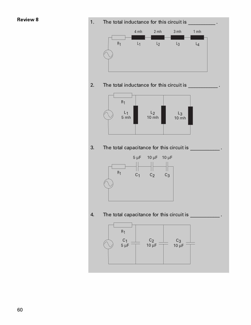
1. The total inductance for this circuit is ___________ .
2. The total inductance for this circuit is ____________ .
3. The total capacitance for this circuit is ____________ .
µ µ µ
4. The total capacitance for this circuit is ____________ .
µ µ µ
Review 8

61
Inductive and Capacitive Reactance
In a purely resistive AC circuit, opposition to current flow iscalled resistance. In an AC circuit containing only inductance,capacitance, or both, opposition to current flow is calledreactance. Total opposition to current flow in an AC circuitthat contains both reactance and resistance is called imped-ance designated by the symbol Z. Reactance and imped-ance are expressed in ohms.
Inductance only affects current flow when the current ischanging. Inductance produces a self-induced voltage(counter emf) that opposes changes in current. In an ACcircuit, current is changing constantly. Inductance in an ACcircuit, therefore, causes a continual opposition. This opposi-tion to current flow is called inductive reactance, and isdesignated by the symbol XL.
Inductive reactance is dependent on the amount of induc-tance and frequency. If frequency is low current has moretime to reach a higher value before the polarity of the sinewave reverses. If frequency is high current has less time toreach a higher value. In the following illustration, voltageremains constant. Current rises to a higher value at a lowerfrequency than a higher frequency.
The formula for inductive reactance is:
XL fL
XL
=× × ×
2π= 2 3 .14 frequency inductance
Inductive reactance

62
Phase relationshipbetween current andvoltage in an inductivecircuit
In a 60 hertz, 10 volt circuit containing a 10 mh inductor, theinductive reactance would be:
XL fL
XL
XL
== × × ×=
2
2 3 14 60 010
3 768
π. .
.
Ω
Once inductive reactance is known, Ohms Law can be usedto calculate reactive current.
IE
Z
I
I amps
=
=
=
10
3 768
2 65
.
.
Current does not rise at the same time as the source voltagein an inductive circuit. Current is delayed depending on theamount of inductance. In a purely resistive circuit, current andvoltage rise and fall at the same time. They are said to be inphase. In this circuit there is no inductance, resistance andimpedance are the same.
In a purely inductive circuit, current lags behind voltage by 90degrees. Current and voltage are said to be out of phase. Inthis circuit, impedance and inductive reactance are the same.

63
All inductive circuits have some amount of resistance. ACcurrent will lag somewhere between a purely resistive circuit,and a purely inductive circuit. The exact amount of lag de-pends on the ratio of resistance and inductive reactance. Themore resistive a circuit is, the closer it is to being in phase.The more inductive a circuit is, the more out of phase it is. Inthe following illustration, resistance and inductive reactanceare equal. Current lags voltage by 45 degrees.
Ω
Ω
When working with a circuit containing elements of induc-tance, capacitance, and resistance, impedance must becalculated. Because electrical concepts deal with trigonomet-ric functions, this is not a simple matter of subtraction andaddition. The following formula is used to calculate imped-ance in an inductive circuit:
Z R XL= +2 2
In the circuit illustrated above, resistance and inductive reac-tance are each 10 ohms. Impedance is 14.1421 ohms. Asimple application of Ohms Law can be used to find totalcircuit current.
Z
Z
Z
= +
==
10 2 10 2
200
14 1421. Ω
Another way to represent this is with a vector. A vector is agraphic representation of a quantity that has direction andmagnitude. A vector on a map might indicate that one city is50 miles southwest from another. The magnitude is 50 miles,and the direction is southwest. Vectors are also used to showelectrical relationships. As mentioned earlier, impedance (Z)is the total oppositon to current flow in an AC circuit contain-ing resistance, inductance, and capacitance. The following
Calculating impedance inan inductive circuit
Vectors
64
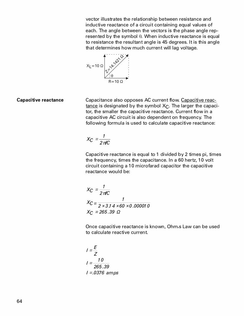
vector illustrates the relationship between resistance andinductive reactance of a circuit containing equal values ofeach. The angle between the vectors is the phase angle rep-resented by the symbol q. When inductive reactance is equalto resistance the resultant angle is 45 degrees. It is this anglethat determines how much current will lag voltage.
θ
Ω
Ω
Capacitance also opposes AC current flow. Capacitive reac-tance is designated by the symbol XC. The larger the capaci-tor, the smaller the capacitive reactance. Current flow in acapacitive AC circuit is also dependent on frequency. Thefollowing formula is used to calculate capacitive reactance:
XCfC
= 1
2π
Capacitive reactance is equal to 1 divided by 2 times pi, timesthe frequency, times the capacitance. In a 60 hertz, 10 voltcircuit containing a 10 microfarad capacitor the capacitivereactance would be:
XCfC
XC
XC
=
= × × ×=
1
2
1
2 3 14 60 0 000010
265 39
π
. .
. Ω
Once capacitive reactance is known, Ohms Law can be usedto calculate reactive current.
IE
Z
I
I amps
=
=
=
10
265 39
0376
.
.
Capacitive reactance

65
Phase relationship betweencurrent and voltage in acapacitive circuit
The phase relationship between current and voltage areopposite to the phase relationship of an inductive circuit. In apurely capacitive circuit, current leads voltage by 90 degrees.
All capacitive circuits have some amount of resistance. ACcurrent will lead somewhere between a purely resistivecircuit and a purely capacitive circuit. The exact amount oflead depends on the ratio of resistance and capacitive reac-tance. The more resistive a circuit is, the closer it is to beingin phase. The more capacitive a circuit is, the more out ofphase it is. In the following illustration, resistance andcapacitive reactance are equal. Current leads voltage by45 degrees.
Ω
Ω
The following formula is used to calculate impedance in acapacitive circuit:
Z R XC= +2 2
In the circuit illustrated above, resistance and capacitivereactance are each 10 ohms. Impedance is 14.1421 ohms.
Z
Z
Z
= +
==
10 2 10 2
200
14 1421. Ω
Calculating impedance in acapacitive circuit

66
The following vector illustrates the relationship betweenresistance and capacitive reactance of a circuit containingequal values of each. The angle between the vectors is thephase angle represented by the symbol q. When capacitivereactance is equal to resistance the resultant angle is -45degrees. It is this angle that determines how much currentwill lead voltage.
θ
Ω
Ω
1. In a circuit containing inductance, capacitance, orboth, opposition to current flow is called____________ .
2. Total opposition to current flow in a circuit that con-tains both reactance and resistance is called____________ .
3. In a 50 hertz circuit, containing a 10 mh inductor, theinductive reactance is ____________ ohms.
4. In a purely inductive circuit,
a. current and voltage are in phaseb. current leads voltage by 90 degreesc. current lags voltage by 90 degrees
5. In a purely capacitive circuit,
a. current and voltage are in phaseb. current leads voltage by 90 degreesc. current lags voltage by 90 degrees
6. In a 50 hertz circuit, containing a 10 microfarad ca-pacitor, the capacitive reactance is ____________ohms.
7. In a circuit with 5 W resistance, and 10 W inductivereactance, impedance is ____________ ohms.
8. In a circuit with 5 W resistance, and 4 W capacitivereactance, impedance is ____________ ohms.
Review 9
67
Series R-L-C Circuit
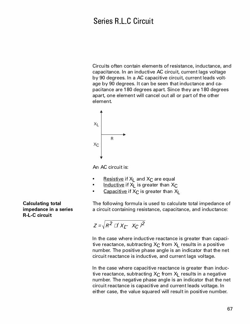
Circuits often contain elements of resistance, inductance, andcapacitance. In an inductive AC circuit, current lags voltageby 90 degrees. In a AC capacitive circuit, current leads volt-age by 90 degrees. It can be seen that inductance and ca-pacitance are 180 degrees apart. Since they are 180 degreesapart, one element will cancel out all or part of the otherelement.
An AC circuit is:
Resistive if XL and XC are equal Inductive if XL is greater than XC Capacitive if XC is greater than XL
The following formula is used to calculate total impedance ofa circuit containing resistance, capacitance, and inductance:
Z R XL XC= + −2 2( )
In the case where inductive reactance is greater than capaci-tive reactance, subtracting XC from XL results in a positivenumber. The positive phase angle is an indicator that the netcircuit reactance is inductive, and current lags voltage.
In the case where capacitive reactance is greater than induc-tive reactance, subtracting XC from XL results in a negativenumber. The negative phase angle is an indicator that the netcircuit reactance is capacitive and current leads voltage. Ineither case, the value squared will result in positive number.
Calculating totalimpedance in a seriesR-L-C circuit

68
Calculating reactance andimpedance in a seriesR-L-C circuit
In the following 120 volt, 60 hertz circuit, resistance is 1000 W,inductance is 5 mh, and capacitance is 2 mF.
Ω µ
To calculate total impedance, first calculate the value of XLand XC, then impedance can be calculated.
XL fL
XL
XL
== × ×=
2
6 28 60 005
1 884
π. .
.
Ω
XCfC
XC
XC
=
=× ×
=
1
2
1
6 28 60 000002
1 327
π
. .
, Ω
Z R XL XC
Z
Z
Z
Z
Z
= + −
= + −
= + −
= +
==
2 2
1000 2 1 884 1 327 2
1 000 000 1 325 116 2
1 000 000 1 755 932 41
2 755 932 41
1 660 1
( )
( . , )
, , ( , . )
, , , , .
, , .
, . Ω
Ohms Law can be applied to calculate total circuit current.
IE
Z
I
I amps
=
=
=
120
1 660 1
072
, .
.
Calculating circuit currentin a series R-L-C circuit

69
Parallel R-L-C Circuit
Total impedance (Zt) can be calculated in a parallel R-L-Ccircuit if values of resistance and reactance are known. Onemethod of calculating impedance involves first calculatingtotal current, then using the following formula:
ZtEt
It=
Total current is the vector sum of current flowing through theresistance plus, the difference between inductive current andcapacitive current. This is expressed in the following formula:
It IR IC IL= + −2 2( )
In the following 120 volt, 60 hertz circuit, Capacitive reactancehas been calculated to be 25 W and inductive reactance 50 W.Resistance is 1000 W.
Ω Ω Ω
A simple application of Ohms Law will find the branch cur-rents. Remember, voltage is constant throughout a parallelcircuit.
IRE
R
IR
IR amps
=
=
=
120
1000
12.
Calculating impedance in aparallel R-L-C circuit

70
ILE
XL
IL
IL amps
=
=
=
120
50
2 4.
ICE
XC
IC
IC amps
=
=
=
120
25
4 8.
Once the branch currents are known, total current can becalculated.
It IR IC IL
It
It
It
It amps
= + −
= + −
= +
==
2 2
122 4 8 2 4 2
0144 5 76
5 7744
2 4
( )
. ( . . )
. .
.
.
Impedance is now found with an application of Ohms Law.
ZtEt
It
Zt
Zt
=
=
=
120
2 4
50
.
Ω
71
Power consumed by a resistor is dissipated in heat and notreturned to the source. This is true power. True power is therate at which energy is used. Current in an AC circuit rises topeak values and diminishes to zero many times a second. Theenergy stored in the magnetic field of an inductor, or plates ofa capacitor, is returned to the source when current changesdirection. Power in an AC circuit is the vector sum of truepower and reactive power. This is called apparent power.True power is equal to apparent power in a purely resistivecircuit because voltage and current are in phase. Voltage andcurrent are also in phase in a circuit containing equal valuesof inductive reactance and capacitive reactance. If voltageand current are 90 degrees out of phase, as would be in apurely capacitive or purely inductive circuit, the average valueof true power is equal to zero. There are high positive andnegative peak values of power, but when added together theresult is zero.
The formula for apparent power is:
P EI=
Apparent power is measured in volt-amps (VA).
True power is calculated from another trigonometric function,the cosine of the phase angle (cos q). The formula for truepower is:
P EI= cos θ
True power is measured in watts.
Power and Power Factor in an AC Circuit
True power andapparent power formulas

72
In a purely resistive circuit, current and voltage are in phase.There is a zero degree angle displacement between currentand voltage. The cosine of zero is one. Multiplying a value byone does not change the value. In a purely resistive circuitthe cosine of the angle is ignored.
In a purely reactive circuit, either inductive or capacitive,current and voltage are 90 degrees out of phase. The cosineof 90 is zero. Multiplying a value times zero results in a zeroproduct. No power is consumed in a purely reactive circuit.
In the following 120 volt circuit, It is equal to 84.9 milliamps.Inductive reactance is 100 W and capacitive reactance is1100 W. The phase angle is -45 degrees. By referring to atrigonometric table, the cosine of -45 degrees is foundto be .7071.
Ω Ω Ω
The apparent power consumed by the circuit is:
P EI
P
P VA
== ×=
120 0849
10 2
.
.
The true power consumed by the circuit is:
P EI
P
P
== × ×=
watts
cos
. .
.
θ120 0849 7071
7 2
Another formula for true power is:
P I R
P
P
=
= ×=
2
0849 2 1000
7 2
.
. watts
Calculating apparent powerin a simple R-L-C circuit

73
Power factor Power factor is the ratio of true power to apparent power inan AC circuit. Power factor is expressed in the followingformula:
PFPT
PA=
Power factor can also be expressed using the formulas fortrue power and apparent power. The value of EI cancels outbecause it is the same in the numerator and denominator.Power factor is the cosine of the angle.
PFEI
EI
PF
=
=
cos
cos
θ
θ
In a purely resistive circuit, where current and voltage are inphase, there is no angle of displacement between current andvoltage. The cosine of a zero degree angle is one. The powerfactor is one. This means that all energy delivered by thesource is consumed by the circuit and dissipated in the formof heat.
In a purely reactive circuit, voltage and current are 90 degreesapart. The cosine of a 90 degree angle is zero. The powerfactor is zero. This means the circuit returns all energy itreceives from the source to the source.
In a circuit where reactance and resistance are equal, voltageand current are displaced by 45 degrees. The cosine of a 45degree angle is .7071. The power factor is .7071. This meansthe circuit has used approximately 70% of the energy sup-plied by the source and returned approximately 30%.

74
1. An AC circuit is ____________ if inductive reactanceand capacitive reactance are equal.
2. A series AC circuit is ____________ if there is moreinductive reactance than capacitive reactance.
3. A series AC circuit is ____________ if there is morecapacitive reactance than inductive reactance.
4. In a 120 VAC, 60 hertz series circuit, with 1000 W ofresistance, 10 mh of inductance and 4 mF of capaci-tance, impedance is ____________ W and current is____________ amps.
5. In the illustrated circuit,
Ω Ω Ω
It is ____________ amps, and impedance is____________ W.
6. True power is measured in ____________ .
7. A circuit with .2 amps flowing through 100 W ofresistance, is consuming ____________ watts.
Review 10

75
Mutual induction
Transformers
Transformers are electromagnetic devices that transfer elec-trical energy from one circuit to another by mutual induction.Mutual induction is the coupling of inductances by theirmutual magnetic fields. In a single-phase transformer thereare two coils, a primary and a secondary coil. The followingcircuit illustrates mutual induction. The AC generator provideselectrical power to the primary coil. The magnetic field pro-duced by the primary induces a voltage into the secondarycoil, which supplies power to a load.
Transformers are used to step a voltage up to a higher level,or down to a lower level. Transformers are used extensivelyin power distribution systems, allowing power companies totransfer electrical energy many miles. Power generatorstypically generate high voltages. This voltage varies, depend-ing on the generator, but a typical voltage might be 15 KV.The voltage is stepped up through a transformer to higherlevels for transmission to substations. Typical voltages rangefrom 115 KV to 765 KV. The electrical power is received atsubstation transformers many miles away where it is steppeddown. Typical voltage might be 34 KV or 69 KV. From here,electrical power is fed to a distribution substation. It can alsobe fed directly to factory locations. If the power is fed to afactory, transformers at the factory site reduce the voltage tousable levels. The power fed to a distribution substation isreduced by transformers at the substation for factory andhome use.

76
Mutual inductance between two coils depends on their fluxlinkage. Maximum coupling occurs when all the lines of fluxfrom the primary coil cut through the secondary winding. Theamount of coupling which takes place is referred to ascoefficient of coupling. To maximize coefficient of coupling,both coils are often wound on an iron core which is used toprovide a path for the lines of flux. The following discussionof step-up and step-down transformers applies to transform-ers with an iron core.
There is a direct relationship between voltage, impedance,current, and the number of coil turns in a transformer. Thisrelationship can be used to find either primary or secondaryvoltage, current, and the number of turns in each coil. It isthe number of turns which determine if a transformer is astep up or step down transformer. The following rules-of-thumb apply to transformers:
If the primary coil has fewer turns than the secondarycoil, it is a step-up transformer.
If the primary coil has more turns than the secondarycoil, it is a step-down transformer.
When the number of turns on the primary and seconday coilsof a transformer are equal, input voltage, impedance, andcurrent are equal to output voltage, impedance, and current.
Coefficient of coupling
Voltage, current, and thenumber of turns in a coil

77
A step-up transformer is used when it is desirable to stepvoltage up in value. The following circuit illustrates a step-uptransformer. The primary coil has fewer turns than the sec-ondary coil. The number of turns in a transformer is given asa ratio. When the primary has fewer turns than the secondary,voltage and impedance are stepped up. In the circuit illus-trated, voltage is stepped up from 120 VAC to 240 VAC.Because impedance is also stepped up, current is steppeddown from 10 amps to 5 amps.
A step-down transformer is used when it is desirable to stepvoltage down in value. The following circuit illustrates a step-down transformer. The primary coil has more turns than thesecondary coil. The step-down ratio is 2:1. Voltage andimpedance are stepped down, current is stepped up.
Step-up transformer
Step-down transformer

78
120 or 240 VAC single-phase transformers are used to supplylighting, receptacle, and small appliance loads. A transformerwith a 240 VAC secondary can be used to supply 240 VACto larger appliances such as stoves, air conditioners andheaters. A 240 VAC secondary can be tapped in the centerto provide two sources of 120 VAC power.
There are a number of useful formulas for calculating, volt-age, current, and the number of turns between the primaryand secondary of a transformer. These formulas can be usedwith either step-up or step-down transformers. The followinglegend applies to the transformer formulas:
ES = secondary voltageEP = primary voltageIS = secondary currentIP = primary currentNS = turns in the secondary coilNP = turns in the primary coil
To find voltage:
ESEP IP
IS= ×
EPES IS
IP= ×
To find current:
ISEP IP
ES= ×
IPES IS
EP= ×
To find the number of coil turns:
NSES NP
EP= ×
NPEP NS
ES= ×
Single-phase transformerconnections
Formulas for calculating thenumber of primary andsecondary turns of atransformer

79
Using the values for the step-down transformer in the ex-ample of the previous page, the secondary voltage can beverified.
ESEP IP
IS
ESvolts amps
amps
ES
ES volts
= ×
= ×
=
=
240 5
10
1200
10
120
Transformers are rated in kVA (kilovolt-amps). This rating isused rather than watts because loads are not purely resistive.Only resistive loads are measured in watts. The kVA ratingdetermines the current a transformer can deliver to its loadwithout overheating. Given volts and amps, kVA can be calcu-lated. Given kVA and volts, amps can be calculated.
kVAvolts amps
ampskVA
volts
= ×
= ×1000
1000
Using the illustrated step-down transformer, the kVA ratingcan be calculated. The kVA rating of a transformer is the samefor both the primary and the secondary.
Primary kVA = ×240 5
1000
Primary kVA = 1.2 kVA
Secondary kVA = ×120 10
1000
Secondary kVA = 1.2 kVA
Most of the electrical energy provided to the primary of atransformer is transferred to the secondary. Some energy,however, is lost in heat in the wiring or the core. Some lossesin the core can be reduced by building the core of a numberof flat sections called laminations.
Transformer losses
Transformer ratings

80
Three-Phase Transformers
Three-phase transformers are used when three-phase poweris required for larger loads such as industrial motors. Thereare two basic three-phase transformer connections, delta andwye. Delta transformers are used where the distance fromthe supply to the load is short. A delta is like three single-phase transformers connected together. The secondary of adelta transformer is illustrated below. For simplicity, only thesecondary of a three-phase transformer is shown. The volt-ages shown on the illustration are secondary voltages avail-able to the load. Delta transformers are schematically drawnin a triangle. The voltages across each winding of the deltatriangle represents one phase of a three phase system. Thevoltage is always the same between any two wires. A singlephase (L1 to L2) can be used to supply single phase loads. Allthree phases are used to supply three phase loads.
L1 to L2 = 480 voltsL2 to L3 = 480 voltsL1 to L3 = 480 volts
Delta connections

81
When current is the same in all three coils, it is said to bebalanced. In each phase, current has two paths to follow. Forexample, current flowing from L1 to the connection point atthe top of the delta can flow down through one coil to L2, anddown through another coil to L3. When current is balanced,coil current is 58% of the line current measured on eachphase. If the line current is 50 amps on each phase, coil cur-rent would be 29 amps.
When current is different in all three coils, it is unbalanced.The following diagram depicts an unbalanced system.
Though current is usually measured with an ammeter, linecurrent of an unbalanced delta transformer can be calculatedwith the following formulas:
IL IA IB IA IB
IL IB IC IB IC
IL IA IC IA IC
12 2
22 2
32 2
= + + ×
= + + ×
= + + ×
( )
( )
( )
Balanced delta current
Unbalanced delta current

82
The wye connection is also known as a star connection.Three transformers are connected to form a Y shape. Thewye transformer secondary, (shown below) has four leads,three phase conductors, and one neutral. The voltage acrossany phase (line-to-neutral) will always be less than the line-to-line voltage. The line-to-line voltage is 1.732 times the line-to-neutral voltage. In the circuit below, line-to-neutral voltageis 277 volts. Line-to-line voltage will be 480 volts (277 x1.732).
1. If the primary of a transformer has more turns thanthe secondary, it is a ____________ transformer.
2. If the primary of a transformer has fewer turns thanthe secondary, it is a ____________ transformer.
3. The secondary voltage of an iron-core transformerwith 240 volts on the primary, 40 amps on the pri-mary, and 20 amps on the secondary is ____________volts.
4. A transformer with a 480 volt, 10 amp primary, and a240 volt, 20 amp secondary will be rated for____________ kVA.
5. A wye connected, three-phase transformer second-ary, with 240 volts line-to-line will have ____________volts line-to-neutral.
Wye connections
Review 11

83
Review 1
Review 2
Review 3
Review 4
Review 5
Review 6
Review 7
Review 8
Review 9
Review 10
1) electron (-), proton (+), neutron (neutral); 2) free electrons;3) many; 4) a, c, e, g; 5) many, few.
1) electrons; 2) negative; 3) positive; 4) repel, attract;5) voltage; 6) b; 7) a.
1) IE
R= ; 2) amps, volts, ohms; 3) .5 amps; 4) 45 W;
5) 2 amps; 6) 6 volts, 6 volts; 7) 20 volts, 80 volts.
1) 5 W; 2) 5.45 W; 3) 3.33 W; 4) 12 volts; 5) 6 amps;6) 2.4 amps, 1.6 amps.
1) 12 W, 22 W; 2) 40 W, 13.33 W.
1) power; 2) P = E x I; 3) 36 watts; 4) iron, north-south;5)north, south; 6) left, thumb, lines of flux.
1) sine wave; 2) 120 degrees; 3) one; 4) -129.9 volts;5) 106.05 volts rms.
1) 10 mh; 2) 2.5 mh; 3) 2.5 mF; 4) 25 mF.
1) reactance; 2) impedance; 3) 3.14 W; 4) c; 5) b; 6) 318.5 W;7) 11.18 W; 8) 6.4 W.
1) resistive; 2) inductive; 3) capacitive; 4) 1198 W, .1 amp;5) 84.9 milliamps,1414.2 W; 6) watts; 7) 4 watts;
1) step-down; 2) step-up; 3) 480 volts; 4) 4.8 kVA;5) 138.56 volts.
Review Answers
Review 11

84
The final exam is intended to be a learning tool. The bookmay be used during the exam. A tear-out answer sheet isprovided. After completing the test, mail the answer sheet infor grading. A grade of 70% or better is passing. Upon suc-cessful completion of the test a certificate will be issued.Those receiving a score of less than 70% will be provided asecond test.
1. A material that is a good insulator is
a. copper c. silverb. aluminum d. rubber
2. A material with more protons than electrons has a
a. negative charge c. neutral chargeb. positive charge d. no charge
3. In a simple electric circuit with a 12 volt supply, and a24 W resistor, current is
a. 2 amps c. .2 ampsb. 5 amps d. .5 amps
4. The total resistance in a series circuit containing 10 W,10 W, and 10 W resistors is
a. 10 W c. 3.33 Wb. 30 W d. 100 W
5. In a 12 volt series circuit where R1=10 W, R2=20 W, andR3=10 W, current flow through R2 is
a. .3 amps c. .25 ampsb. .5 amps d. 3.33 amps
Final Exam
Questions

85
6. In a circuit containing three 30 W resistors in parallel, thetotal resistance is
a. 30 W c. 10 Wb. 90 W d. .1 W
7. The rate at which work is done is called
a. energy c. efficiencyb. power d. power factor
8. Power in a simple 12 volt, 4 amp series circuit is
a. 3 amps c. 48 ampsb. 3 watts d. 48 watts
9. The instantaneous voltage at 150 degrees of an AC sinewave whose peak voltage is 480 volts is
a. 415.7 volts c. 240 voltsb. 480 volts d. 0 volts
10. The effective voltage of an AC sine wave whose peakvoltage is 480 volts is
a. 415.7 volts c. 480 voltsb. 339.4 volts d. 679 volts
11. The time constant of a series circuit with a 10 millihenryinductor, and a 5 W resistor is
a. 2 milliseconds c. 2 microsecondsb. 2 seconds d. .5 seconds
12. The total inductance of a series circuit containing a10 mh, 20 mh, and 40 mh inductors is
a. 5.7 pF c. 70 Wb. 5.7 mh d. 70 mh
13. The time constant for a series circuit with a 20 W resis-tive and a 4 mF capacitor is
a. 80 microseconds c. 5 microsecondsb. 80 milliseconds d. 5 milliseconds

86
14. Total capacitance for a series circuit containing a 2 mF, 4mF, and 8 mF capacitors is
a. 14 mF c. 1.14 mFb. .875 mF d. 4 mF
15. Total opposition to current flow in an AC circuit thatcontains both reactance and resistance is called
a. resistance c. impedanceb. reactance d. capacitance
16. In a 60 hertz circuit containing 5 millihenrys of induc-tance, inductive reactance is
a. 1.884 W c. .0005 Wb. 1884 W d. .05 W
17. In a purely inductive circuit
a. current leads voltage by 90 degreesb. current lags voltage by 90 degreesc. current and voltage are in phased. current leads voltage by 30 degrees
18. In a series AC circuit with a 20 W resistor and a 10 Winductive reactance, impedance is
a. 30 W c. 14.1 Wb. 10 W d. 22.4 W
19. A series AC circuit containing more capacitive reac-tance than inductive reactance is
a. inductive c. capacitiveb. resistive d. in phase
20. An iron-core transformer with 120 volt, 10 amp pri-mary, and 5 amp secondary is a
a. step down transformer with a 60 volt secondaryb. step up transformer with a 240 volt secondaryc. step up transformer with a 480 volt secondaryd. step down transformer with a 30 volt secondary

87
Notes

88
Notes


![Basics of Electricity [Siemens]](https://img.pdfslide.net/doc/110x75/552d59804a79593c578b4655/basics-of-electricity-siemens.jpg)