Embed Size (px)
Citation preview
Marisa Bazañez-Borgert JASS2006
Basics of SPECT, PET and PET/CT Imaging 1
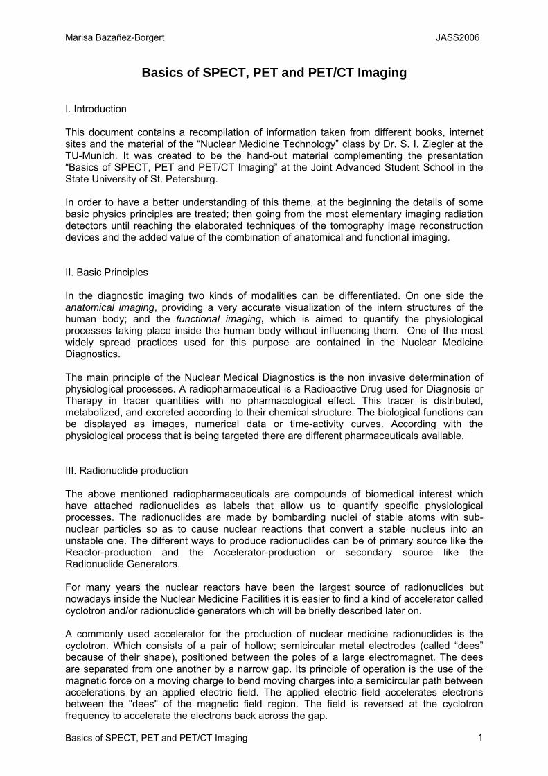
Basics of SPECT, PET and PET/CT Imaging I. Introduction This document contains a recompilation of information taken from different books, internet sites and the material of the “Nuclear Medicine Technology” class by Dr. S. I. Ziegler at the TU-Munich. It was created to be the hand-out material complementing the presentation “Basics of SPECT, PET and PET/CT Imaging” at the Joint Advanced Student School in the State University of St. Petersburg. In order to have a better understanding of this theme, at the beginning the details of some basic physics principles are treated; then going from the most elementary imaging radiation detectors until reaching the elaborated techniques of the tomography image reconstruction devices and the added value of the combination of anatomical and functional imaging. II. Basic Principles In the diagnostic imaging two kinds of modalities can be differentiated. On one side the anatomical imaging, providing a very accurate visualization of the intern structures of the human body; and the functional imaging, which is aimed to quantify the physiological processes taking place inside the human body without influencing them. One of the most widely spread practices used for this purpose are contained in the Nuclear Medicine Diagnostics. The main principle of the Nuclear Medical Diagnostics is the non invasive determination of physiological processes. A radiopharmaceutical is a Radioactive Drug used for Diagnosis or Therapy in tracer quantities with no pharmacological effect. This tracer is distributed, metabolized, and excreted according to their chemical structure. The biological functions can be displayed as images, numerical data or time-activity curves. According with the physiological process that is being targeted there are different pharmaceuticals available. III. Radionuclide production The above mentioned radiopharmaceuticals are compounds of biomedical interest which have attached radionuclides as labels that allow us to quantify specific physiological processes. The radionuclides are made by bombarding nuclei of stable atoms with sub-nuclear particles so as to cause nuclear reactions that convert a stable nucleus into an unstable one. The different ways to produce radionuclides can be of primary source like the Reactor-production and the Accelerator-production or secondary source like the Radionuclide Generators. For many years the nuclear reactors have been the largest source of radionuclides but nowadays inside the Nuclear Medicine Facilities it is easier to find a kind of accelerator called cyclotron and/or radionuclide generators which will be briefly described later on. A commonly used accelerator for the production of nuclear medicine radionuclides is the cyclotron. Which consists of a pair of hollow; semicircular metal electrodes (called “dees” because of their shape), positioned between the poles of a large electromagnet. The dees are separated from one another by a narrow gap. Its principle of operation is the use of the magnetic force on a moving charge to bend moving charges into a semicircular path between accelerations by an applied electric field. The applied electric field accelerates electrons between the "dees" of the magnetic field region. The field is reversed at the cyclotron frequency to accelerate the electrons back across the gap.
Marisa Bazañez-Borgert JASS2006
Basics of SPECT, PET and PET/CT Imaging 2
Cyclotron operation principle
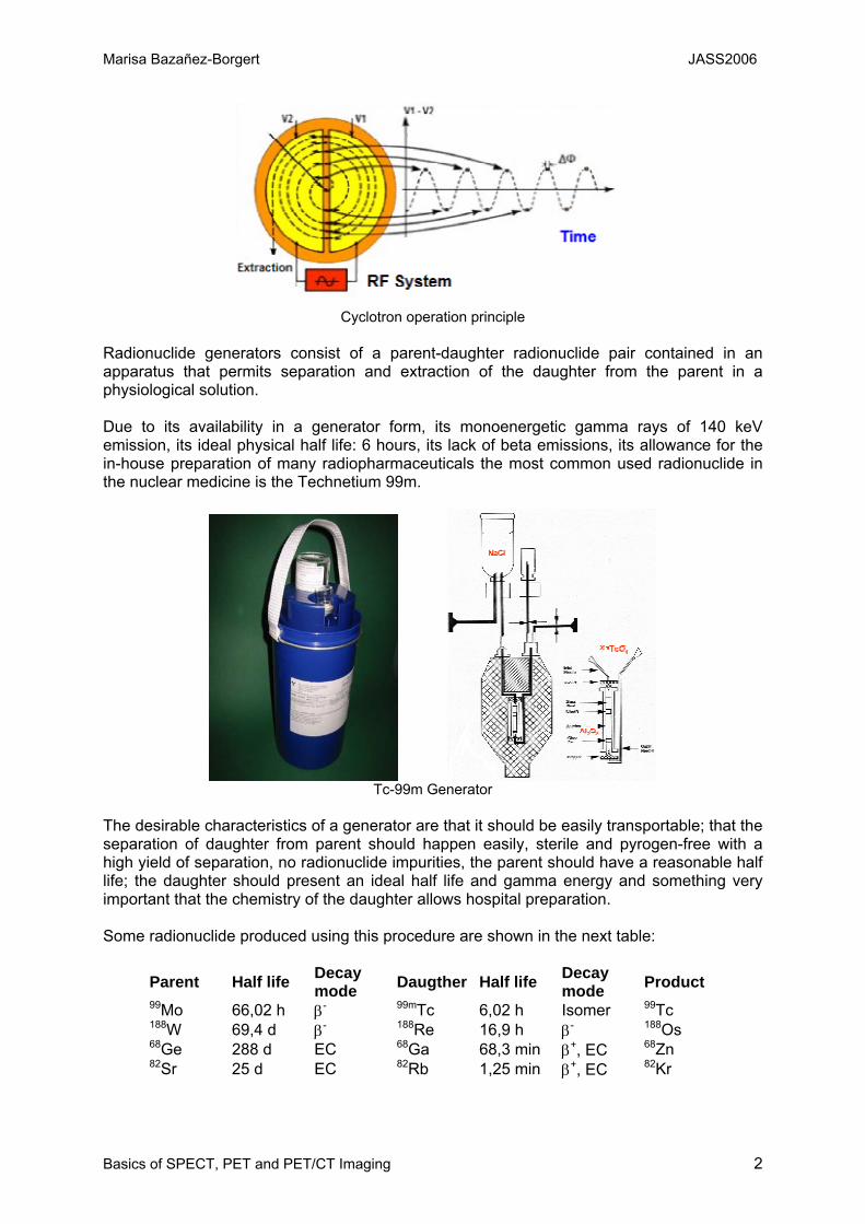
Radionuclide generators consist of a parent-daughter radionuclide pair contained in an apparatus that permits separation and extraction of the daughter from the parent in a physiological solution. Due to its availability in a generator form, its monoenergetic gamma rays of 140 keV emission, its ideal physical half life: 6 hours, its lack of beta emissions, its allowance for the in-house preparation of many radiopharmaceuticals the most common used radionuclide in the nuclear medicine is the Technetium 99m.
Tc-99m Generator
The desirable characteristics of a generator are that it should be easily transportable; that the separation of daughter from parent should happen easily, sterile and pyrogen-free with a high yield of separation, no radionuclide impurities, the parent should have a reasonable half life; the daughter should present an ideal half life and gamma energy and something very important that the chemistry of the daughter allows hospital preparation. Some radionuclide produced using this procedure are shown in the next table:
Parent Half life Decay mode Daugther Half life Decay
mode Product 99Mo 66,02 h β- 99mTc 6,02 h Isomer 99Tc 188W 69,4 d β- 188Re 16,9 h β- 188Os 68Ge 288 d EC 68Ga 68,3 min β+, EC 68Zn 82Sr 25 d EC 82Rb 1,25 min β+, EC 82Kr
Marisa Bazañez-Borgert JASS2006
Basics of SPECT, PET and PET/CT Imaging 3
IV. Decay Modes As observed on the third and sixth columns of the last table, in order to reach a stable state the radionuclide decay in different modes, namely α emission, β- emission, positron (β+) emission, isomeric transition (γ emission), internal conversion (IC), electron capture (EC) and nuclear fission. For diagnostic nuclear medicine purposes the α and nuclear fission are of relatively little importance. The other modes are briefly described. The isomeric transition consists in the emission of γ-rays. An alternative to γ-ray emission that is especially common among metastable states is decay by internal conversion. In this process, the nucleus decays by transferring energy to an orbital electron which is ejected instead of the γ-ray. It is as if the γ-ray were “internally absorbed” by collision with an orbital electron. In radioactive decay by positron emission (β+), a proton in the nucleus is transformed into a neutron and a positron that is the antiparticle of an ordinary electron. The positron combines with the negative electron in an annihilation reaction. There is a “back to back” emission of annihilation photons that is required for conservation of momentum for the stationary electron-positron pair. The mass-energy equivalent of each particle is 0.511 MeV. Positron emitters are useful in nuclear medicine because two photons are generated per nuclear decay event. The precise directional relationship between the annihilation photons permits the use of “coincidence counting” techniques. The electron capture decay is also known as „inverse β- decay“. In this decay an orbital electron is captured by the nucleus and combines with a proton to form a neutron. Positron emission and EC have the same effect on the parent nucleus. Both are isobaric decay modes that decrease atomic number by one. Among the radioactive nuclides, one finds that β+ decay occurs more frequently among lighter elements, whereas EC is more frequently among heavier elements, since in heavy elements orbital electrons tend to be closer to the nucleus and are more easily captured. For example 18F decays 3% of the cases by EC and 97% by β+ emission. The range of coverage of particle emission in tissue is shown in the following table:
Particle Energy Coverage α (very local Therapy) few MeV < 1mm
β (Therapy) 100 KeV – 1MeV ~ few mm γ (Imaging) 100 – 500 KeV > few cm
The type and energy of emissions from the radionuclide determine the availability of useful photons for counting or imaging. For external detection of a radionuclide inside the body it is very important to consider the interactions that they have with the different materials. The three main interactions of high-energy photons through matter are the photoelectric effect, the Compton scattering and the pair production. V. Interaction of radiation with matter When a photon passes through a thickness of absorber material, the probability that it will experience an interaction depends on its energy and on the composition and thickness of the absorber. The dependence on thickness is relative simple; the thicker the absorber the greater the probability that an interaction will occur.
Marisa Bazañez-Borgert JASS2006
Basics of SPECT, PET and PET/CT Imaging 4
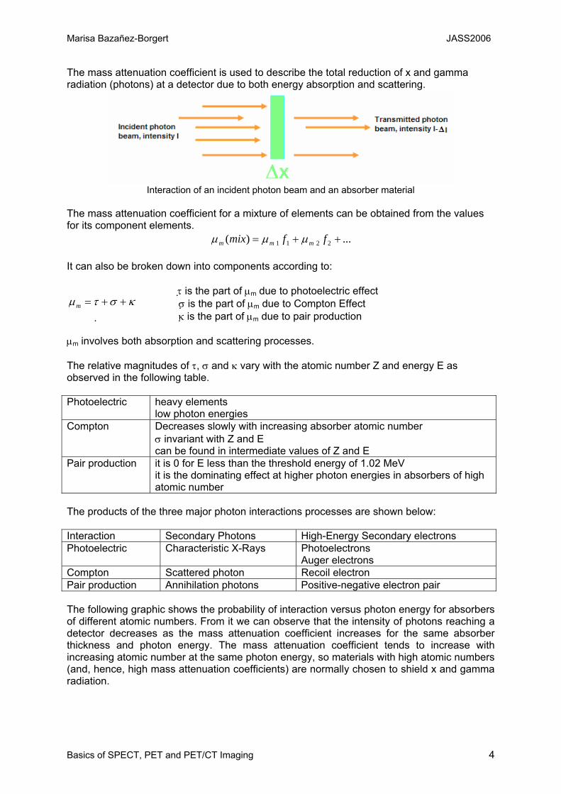
The mass attenuation coefficient is used to describe the total reduction of x and gamma radiation (photons) at a detector due to both energy absorption and scattering.
Interaction of an incident photon beam and an absorber material
The mass attenuation coefficient for a mixture of elements can be obtained from the values for its component elements.
...)( 2211 ++= ffmix mmm µµµ It can also be broken down into components according to:
τ is the part of µm due to photoelectric effect σ is the part of µm due to Compton Effect
κ is the part of µm due to pair production µm involves both absorption and scattering processes. The relative magnitudes of τ, σ and κ vary with the atomic number Z and energy E as observed in the following table. Photoelectric heavy elements
low photon energies Compton Decreases slowly with increasing absorber atomic number
σ invariant with Z and E can be found in intermediate values of Z and E
Pair production it is 0 for E less than the threshold energy of 1.02 MeV it is the dominating effect at higher photon energies in absorbers of high atomic number
The products of the three major photon interactions processes are shown below: Interaction Secondary Photons High-Energy Secondary electrons Photoelectric Characteristic X-Rays Photoelectrons
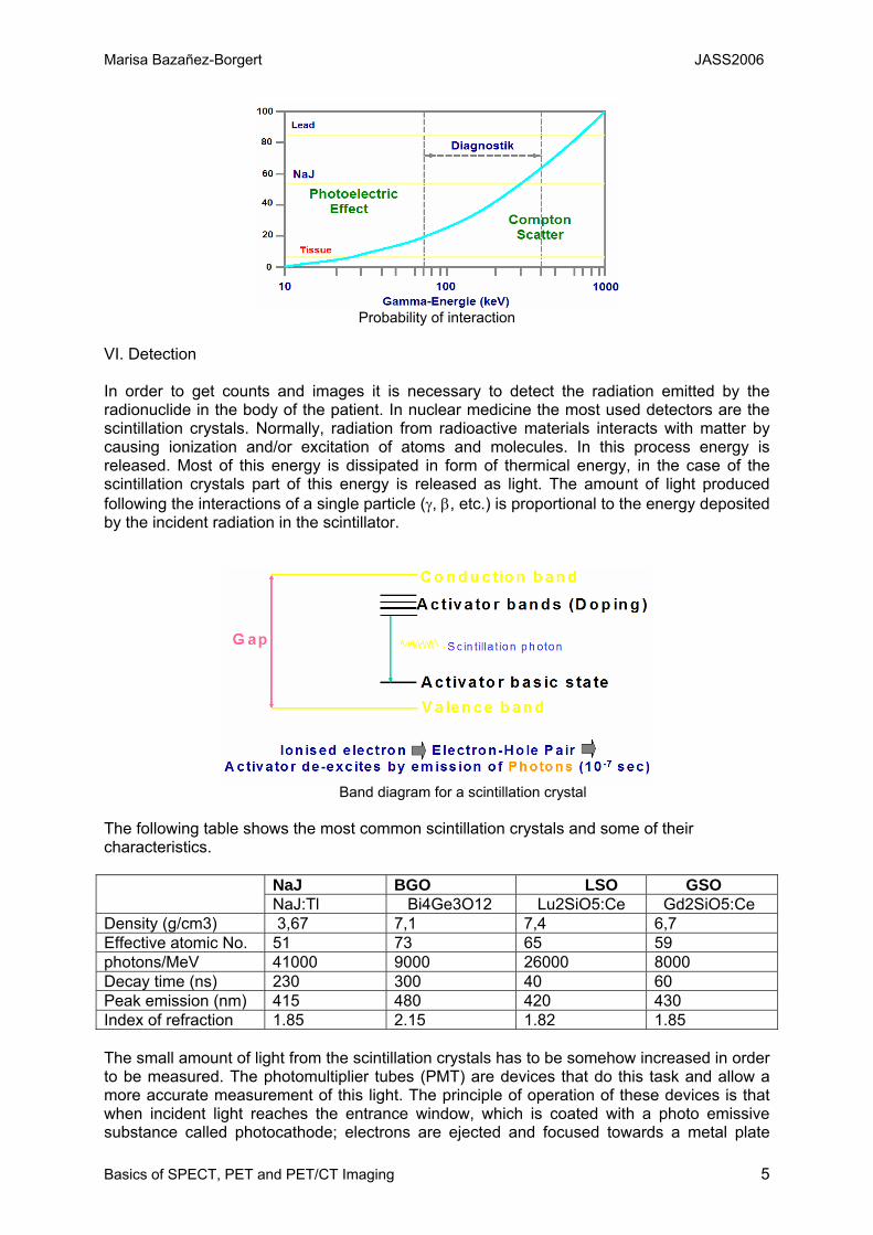
Auger electrons Compton Scattered photon Recoil electron Pair production Annihilation photons Positive-negative electron pair The following graphic shows the probability of interaction versus photon energy for absorbers of different atomic numbers. From it we can observe that the intensity of photons reaching a detector decreases as the mass attenuation coefficient increases for the same absorber thickness and photon energy. The mass attenuation coefficient tends to increase with increasing atomic number at the same photon energy, so materials with high atomic numbers (and, hence, high mass attenuation coefficients) are normally chosen to shield x and gamma radiation.
κστµ ++=m
Marisa Bazañez-Borgert JASS2006
Basics of SPECT, PET and PET/CT Imaging 5
Probability of interaction
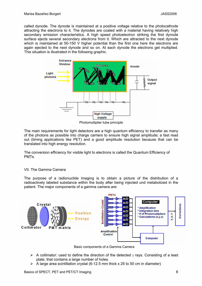
VI. Detection In order to get counts and images it is necessary to detect the radiation emitted by the radionuclide in the body of the patient. In nuclear medicine the most used detectors are the scintillation crystals. Normally, radiation from radioactive materials interacts with matter by causing ionization and/or excitation of atoms and molecules. In this process energy is released. Most of this energy is dissipated in form of thermical energy, in the case of the scintillation crystals part of this energy is released as light. The amount of light produced following the interactions of a single particle (γ, β, etc.) is proportional to the energy deposited by the incident radiation in the scintillator.
Band diagram for a scintillation crystal
The following table shows the most common scintillation crystals and some of their characteristics.
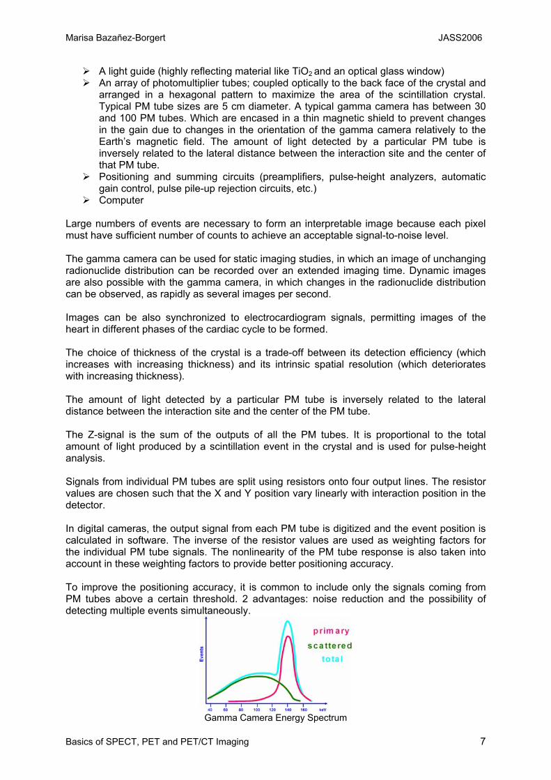
NaJ BGO LSO GSO NaJ:Tl Bi4Ge3O12 Lu2SiO5:Ce Gd2SiO5:Ce Density (g/cm3) 3,67 7,1 7,4 6,7 Effective atomic No. 51 73 65 59 photons/MeV 41000 9000 26000 8000 Decay time (ns) 230 300 40 60 Peak emission (nm) 415 480 420 430 Index of refraction 1.85 2.15 1.82 1.85 The small amount of light from the scintillation crystals has to be somehow increased in order to be measured. The photomultiplier tubes (PMT) are devices that do this task and allow a more accurate measurement of this light. The principle of operation of these devices is that when incident light reaches the entrance window, which is coated with a photo emissive substance called photocathode; electrons are ejected and focused towards a metal plate
Marisa Bazañez-Borgert JASS2006
Basics of SPECT, PET and PET/CT Imaging 6
called dynode. The dynode is maintained at a positive voltage relative to the photocathode attracting the electrons to it. The dynodes are coated with a material having relatively high secondary emission characteristics. A high speed photoelectron striking the first dynode surface ejects several secondary electrons from it. Which are attracted to the next dynode which is maintained at 50-150 V higher potential than the first one here the electrons are again ejected to the next dynode and so on. At each dynode the electrons get multiplied. This situation is illustrated in the following graphic.
Photomultiplier tube principle
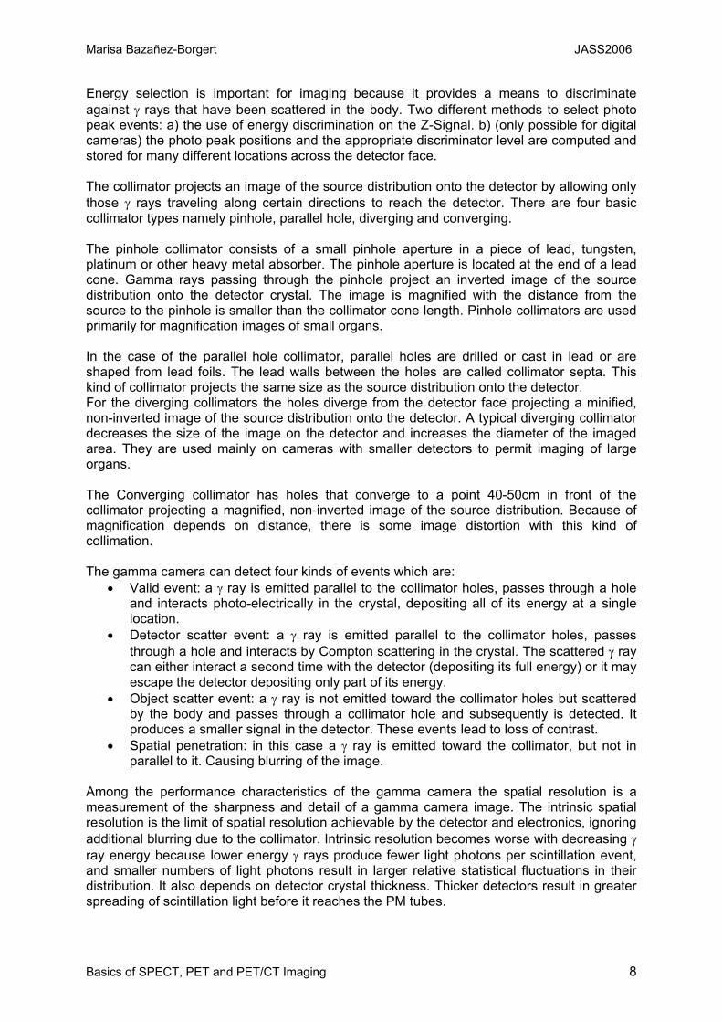
The main requirements for light detectors are a high quantum efficiency to transfer as many of the photons as possible into charge carriers to ensure high signal amplitude; a fast read out (timing applications like PET) and a good amplitude resolution because that can be translated into high energy resolution. The conversion efficiency for visible light to electrons is called the Quantum Efficiency of PMTs. VII. The Gamma Camera The purpose of a radionuclide imaging is to obtain a picture of the distribution of a radioactively labeled substance within the body after being injected und metabolized in the patient. The major components of a gamma camera are:
Basic components of a Gamma Camera
A collimator: used to define the direction of the detected γ rays. Consisting of a lead plate, that contains a large number of holes.
A large area scintillation crystal (6-12.5 mm thick x 25 to 50 cm in diameter)
Marisa Bazañez-Borgert JASS2006
Basics of SPECT, PET and PET/CT Imaging 7
A light guide (highly reflecting material like TiO2 and an optical glass window) An array of photomultiplier tubes; coupled optically to the back face of the crystal and
arranged in a hexagonal pattern to maximize the area of the scintillation crystal. Typical PM tube sizes are 5 cm diameter. A typical gamma camera has between 30 and 100 PM tubes. Which are encased in a thin magnetic shield to prevent changes in the gain due to changes in the orientation of the gamma camera relatively to the Earth’s magnetic field. The amount of light detected by a particular PM tube is inversely related to the lateral distance between the interaction site and the center of that PM tube.
Positioning and summing circuits (preamplifiers, pulse-height analyzers, automatic gain control, pulse pile-up rejection circuits, etc.)
Computer Large numbers of events are necessary to form an interpretable image because each pixel must have sufficient number of counts to achieve an acceptable signal-to-noise level. The gamma camera can be used for static imaging studies, in which an image of unchanging radionuclide distribution can be recorded over an extended imaging time. Dynamic images are also possible with the gamma camera, in which changes in the radionuclide distribution can be observed, as rapidly as several images per second. Images can be also synchronized to electrocardiogram signals, permitting images of the heart in different phases of the cardiac cycle to be formed.
The choice of thickness of the crystal is a trade-off between its detection efficiency (which increases with increasing thickness) and its intrinsic spatial resolution (which deteriorates with increasing thickness). The amount of light detected by a particular PM tube is inversely related to the lateral distance between the interaction site and the center of the PM tube. The Z-signal is the sum of the outputs of all the PM tubes. It is proportional to the total amount of light produced by a scintillation event in the crystal and is used for pulse-height analysis. Signals from individual PM tubes are split using resistors onto four output lines. The resistor values are chosen such that the X and Y position vary linearly with interaction position in the detector. In digital cameras, the output signal from each PM tube is digitized and the event position is calculated in software. The inverse of the resistor values are used as weighting factors for the individual PM tube signals. The nonlinearity of the PM tube response is also taken into account in these weighting factors to provide better positioning accuracy. To improve the positioning accuracy, it is common to include only the signals coming from PM tubes above a certain threshold. 2 advantages: noise reduction and the possibility of detecting multiple events simultaneously.
Gamma Camera Energy Spectrum
Marisa Bazañez-Borgert JASS2006
Basics of SPECT, PET and PET/CT Imaging 8
Energy selection is important for imaging because it provides a means to discriminate against γ rays that have been scattered in the body. Two different methods to select photo peak events: a) the use of energy discrimination on the Z-Signal. b) (only possible for digital cameras) the photo peak positions and the appropriate discriminator level are computed and stored for many different locations across the detector face. The collimator projects an image of the source distribution onto the detector by allowing only those γ rays traveling along certain directions to reach the detector. There are four basic collimator types namely pinhole, parallel hole, diverging and converging. The pinhole collimator consists of a small pinhole aperture in a piece of lead, tungsten, platinum or other heavy metal absorber. The pinhole aperture is located at the end of a lead cone. Gamma rays passing through the pinhole project an inverted image of the source distribution onto the detector crystal. The image is magnified with the distance from the source to the pinhole is smaller than the collimator cone length. Pinhole collimators are used primarily for magnification images of small organs. In the case of the parallel hole collimator, parallel holes are drilled or cast in lead or are shaped from lead foils. The lead walls between the holes are called collimator septa. This kind of collimator projects the same size as the source distribution onto the detector. For the diverging collimators the holes diverge from the detector face projecting a minified, non-inverted image of the source distribution onto the detector. A typical diverging collimator decreases the size of the image on the detector and increases the diameter of the imaged area. They are used mainly on cameras with smaller detectors to permit imaging of large organs. The Converging collimator has holes that converge to a point 40-50cm in front of the collimator projecting a magnified, non-inverted image of the source distribution. Because of magnification depends on distance, there is some image distortion with this kind of collimation. The gamma camera can detect four kinds of events which are:
• Valid event: a γ ray is emitted parallel to the collimator holes, passes through a hole and interacts photo-electrically in the crystal, depositing all of its energy at a single location.
• Detector scatter event: a γ ray is emitted parallel to the collimator holes, passes through a hole and interacts by Compton scattering in the crystal. The scattered γ ray can either interact a second time with the detector (depositing its full energy) or it may escape the detector depositing only part of its energy.
• Object scatter event: a γ ray is not emitted toward the collimator holes but scattered by the body and passes through a collimator hole and subsequently is detected. It produces a smaller signal in the detector. These events lead to loss of contrast.
• Spatial penetration: in this case a γ ray is emitted toward the collimator, but not in parallel to it. Causing blurring of the image.
Among the performance characteristics of the gamma camera the spatial resolution is a measurement of the sharpness and detail of a gamma camera image. The intrinsic spatial resolution is the limit of spatial resolution achievable by the detector and electronics, ignoring additional blurring due to the collimator. Intrinsic resolution becomes worse with decreasing γ ray energy because lower energy γ rays produce fewer light photons per scintillation event, and smaller numbers of light photons result in larger relative statistical fluctuations in their distribution. It also depends on detector crystal thickness. Thicker detectors result in greater spreading of scintillation light before it reaches the PM tubes.
Marisa Bazañez-Borgert JASS2006
Basics of SPECT, PET and PET/CT Imaging 9
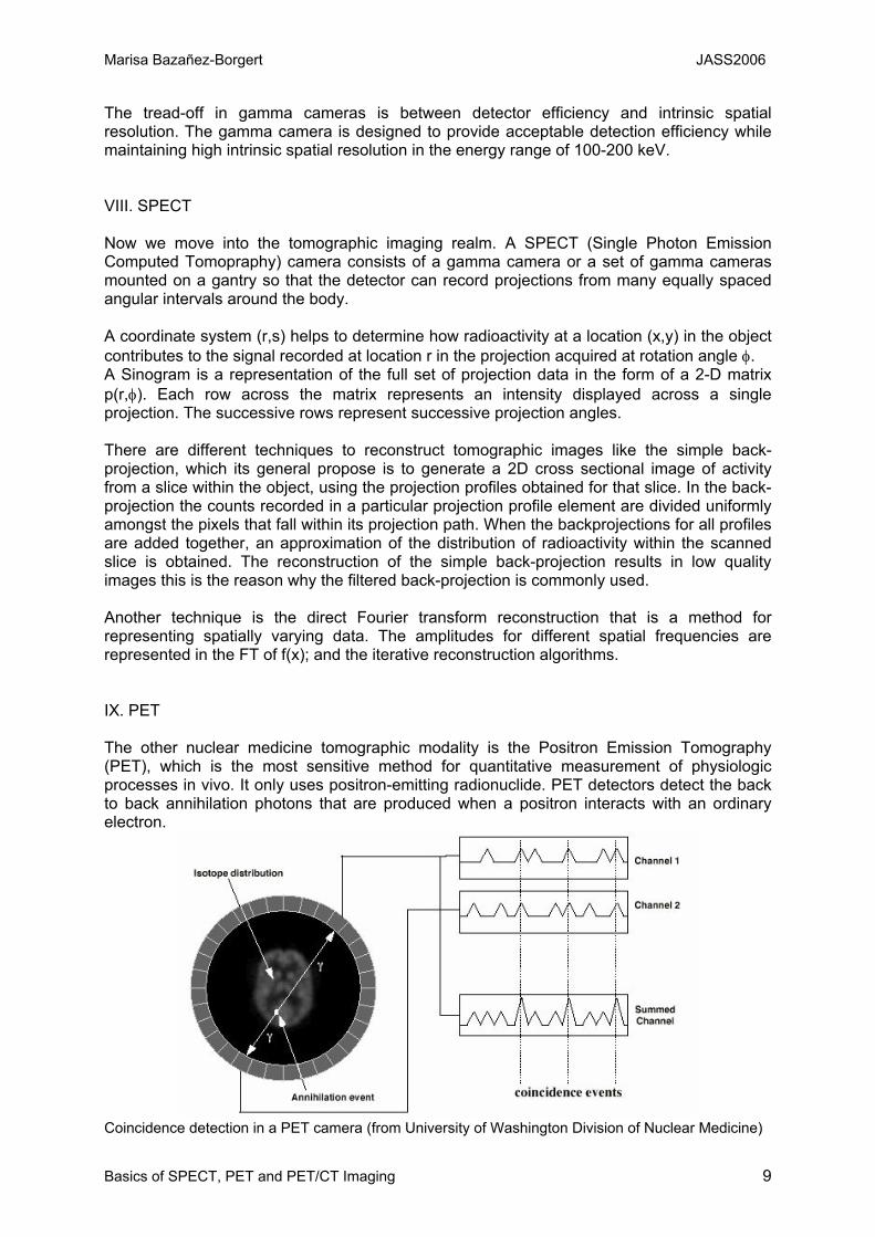
The tread-off in gamma cameras is between detector efficiency and intrinsic spatial resolution. The gamma camera is designed to provide acceptable detection efficiency while maintaining high intrinsic spatial resolution in the energy range of 100-200 keV. VIII. SPECT Now we move into the tomographic imaging realm. A SPECT (Single Photon Emission Computed Tomopraphy) camera consists of a gamma camera or a set of gamma cameras mounted on a gantry so that the detector can record projections from many equally spaced angular intervals around the body. A coordinate system (r,s) helps to determine how radioactivity at a location (x,y) in the object contributes to the signal recorded at location r in the projection acquired at rotation angle φ. A Sinogram is a representation of the full set of projection data in the form of a 2-D matrix p(r,φ). Each row across the matrix represents an intensity displayed across a single projection. The successive rows represent successive projection angles. There are different techniques to reconstruct tomographic images like the simple back-projection, which its general propose is to generate a 2D cross sectional image of activity from a slice within the object, using the projection profiles obtained for that slice. In the back-projection the counts recorded in a particular projection profile element are divided uniformly amongst the pixels that fall within its projection path. When the backprojections for all profiles are added together, an approximation of the distribution of radioactivity within the scanned slice is obtained. The reconstruction of the simple back-projection results in low quality images this is the reason why the filtered back-projection is commonly used. Another technique is the direct Fourier transform reconstruction that is a method for representing spatially varying data. The amplitudes for different spatial frequencies are represented in the FT of f(x); and the iterative reconstruction algorithms. IX. PET The other nuclear medicine tomographic modality is the Positron Emission Tomography (PET), which is the most sensitive method for quantitative measurement of physiologic processes in vivo. It only uses positron-emitting radionuclide. PET detectors detect the back to back annihilation photons that are produced when a positron interacts with an ordinary electron.
Coincidence detection in a PET camera (from University of Washington Division of Nuclear Medicine)
Marisa Bazañez-Borgert JASS2006
Basics of SPECT, PET and PET/CT Imaging 10
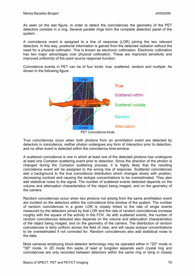
As seen on the last figure, in order to detect the coincidences the geometry of the PET detectors consists in a ring. Several parallel rings form the complete detection panel of the system. A coincidence event is assigned to a line of response (LOR) joining the two relevant detectors. In this way, positional information is gained from the detected radiation without the need for a physical collimator. This is known as electronic collimation. Electronic collimation has two major advantages over physical collimation. These are improved sensitivity and improved uniformity of the point source response function. Coincidence events in PET can be of four kinds: true, scattered, random and multiple. As shown in the following figure.
PET Coincidence kinds
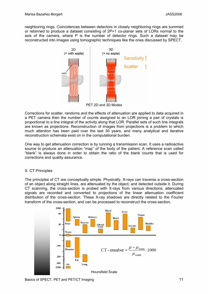
True coincidences occur when both photons from an annihilation event are detected by detectors in coincidence, neither photon undergoes any form of interaction prior to detection, and no other event is detected within the coincidence time-window. A scattered coincidence is one in which at least one of the detected photons has undergone at least one Compton scattering event prior to detection. Since the direction of the photon is changed during the Compton scattering process, it is highly likely that the resulting coincidence event will be assigned to the wrong line of response. Scattered coincidences add a background to the true coincidence distribution which changes slowly with position, decreasing contrast and causing the isotope concentrations to be overestimated. They also add statistical noise to the signal. The number of scattered events detected depends on the volume and attenuation characteristics of the object being imaged, and on the geometry of the camera. Random coincidences occur when two photons not arising from the same annihilation event are incident on the detectors within the coincidence time window of the system. The number of random coincidences in a given LOR is closely linked to the rate of single events measured by the detectors joined by that LOR and the rate of random coincidences increase roughly with the square of the activity in the FOV. As with scattered events, the number of random coincidences detected also depends on the volume and attenuation characteristics of the object being imaged, and on the geometry of the camera. The distribution of random coincidences is fairly uniform across the field of view, and will cause isotope concentrations to be overestimated if not corrected for. Random coincidences also add statistical noise to the data. Most cameras employing block-detector technology may be operated either in "2D" mode or "3D" mode. In 2D mode thin septa of lead or tungsten separate each crystal ring and coincidences are only recorded between detectors within the same ring or lying in closely
Marisa Bazañez-Borgert JASS2006
Basics of SPECT, PET and PET/CT Imaging 11
neighboring rings. Coincidences between detectors in closely neighboring rings are summed or rebinned to produce a dataset consisting of 2P+1 co-planar sets of LORs normal to the axis of the camera, where P is the number of detector rings. Such a dataset may be reconstructed into images using tomographic techniques like the ones discussed by SPECT.
PET 2D and 3D Modes
Corrections for scatter, randoms and the effects of attenuation are applied to data acquired in a PET camera then the number of counts assigned to an LOR joining a pair of crystals is proportional to a line integral of the activity along that LOR. Parallel sets of such line integrals are known as projections. Reconstruction of images from projections is a problem to which much attention has been paid over the last 30 years, and many analytical and iterative reconstruction schemata exist on in the computational burden. One way to get attenuation correction is by running a transmission scan. It uses a radioactive source to produce an attenuation “map” of the body of the patient. A reference scan called “blank” is always done in order to obtain the ratio of the blank counts that is used for corrections and quality assurance. X. CT Principles The principles of CT are conceptually simple. Physically, X-rays can traverse a cross-section of an object along straight lines, are attenuated by the object, and detected outside it. During CT scanning, the cross-section is probed with X-rays from various directions; attenuated signals are recorded and converted to projections of the linear attenuation coefficient distribution of the cross-section. These X-ray shadows are directly related to the Fourier transform of the cross-section, and can be processed to reconstruct the cross-section.
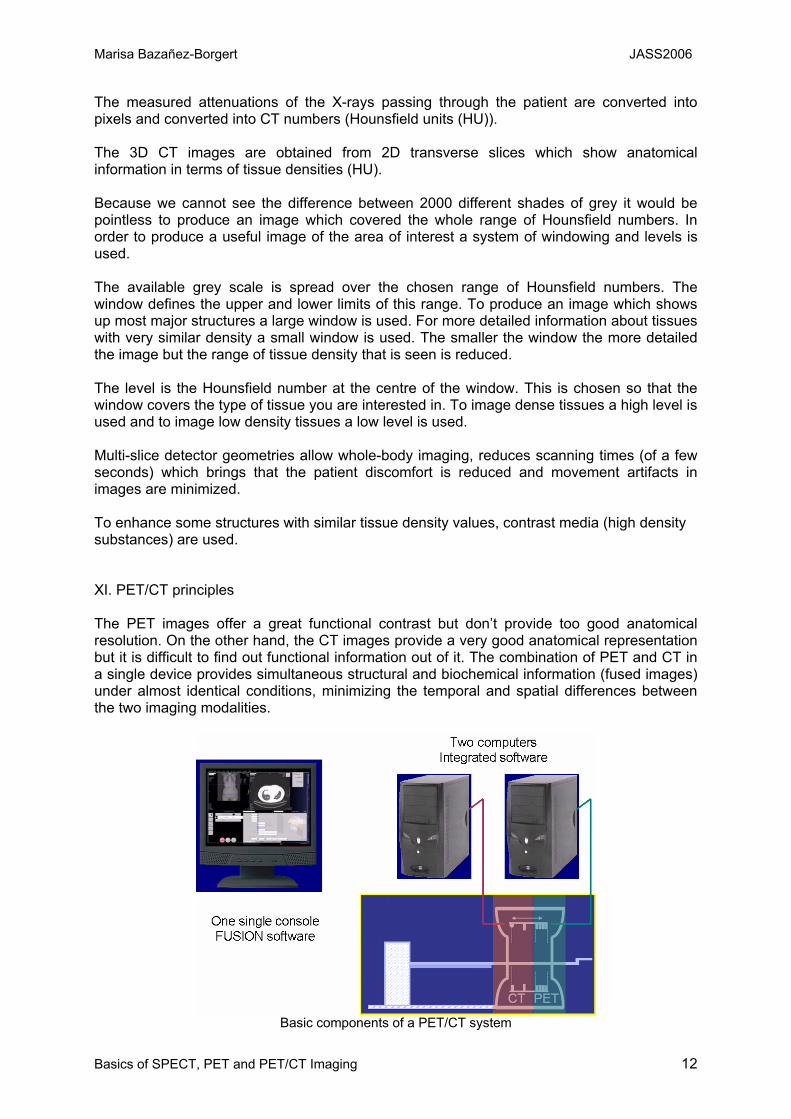
Hounsfield Scale
Marisa Bazañez-Borgert JASS2006
Basics of SPECT, PET and PET/CT Imaging 12
The measured attenuations of the X-rays passing through the patient are converted into pixels and converted into CT numbers (Hounsfield units (HU)). The 3D CT images are obtained from 2D transverse slices which show anatomical information in terms of tissue densities (HU). Because we cannot see the difference between 2000 different shades of grey it would be pointless to produce an image which covered the whole range of Hounsfield numbers. In order to produce a useful image of the area of interest a system of windowing and levels is used. The available grey scale is spread over the chosen range of Hounsfield numbers. The window defines the upper and lower limits of this range. To produce an image which shows up most major structures a large window is used. For more detailed information about tissues with very similar density a small window is used. The smaller the window the more detailed the image but the range of tissue density that is seen is reduced. The level is the Hounsfield number at the centre of the window. This is chosen so that the window covers the type of tissue you are interested in. To image dense tissues a high level is used and to image low density tissues a low level is used. Multi-slice detector geometries allow whole-body imaging, reduces scanning times (of a few seconds) which brings that the patient discomfort is reduced and movement artifacts in images are minimized. To enhance some structures with similar tissue density values, contrast media (high density substances) are used. XI. PET/CT principles The PET images offer a great functional contrast but don’t provide too good anatomical resolution. On the other hand, the CT images provide a very good anatomical representation but it is difficult to find out functional information out of it. The combination of PET and CT in a single device provides simultaneous structural and biochemical information (fused images) under almost identical conditions, minimizing the temporal and spatial differences between the two imaging modalities.
Basic components of a PET/CT system
Marisa Bazañez-Borgert JASS2006
Basics of SPECT, PET and PET/CT Imaging 13
Among the advantages that having this two modalities together offers we can find that the patient stays on the same table for both acquisitions minimizing any intrinsic spatial misalignment; the total examination of PET is notably reduced; because of the transmission scan is being done by the CT reducing in this way the costs of maintenance and of replacing the radioactive source available in the standard PET scanners. The PET/CT examination starts with the injection of the radionuclide. After an uptake time the patient is positioned as comfortable as possible on the table of the PET/CT scanner. Normally a CT-topogram follows. Then the table moves into the start position of the PET system and the emission scan is initiated. By the time the emission PET scan is completed the CT transmission images have been already reconstructed and available for the attenuation and scatter corrections of the emission data. The total time for the images to be ready for diagnostics is restricted to the reconstruction time which is more or less the time taken to have enough counts for each bed position of the PET acquisition. XII. Conclusions The Joint Advanced Students School in San Petersburg will be giving us the opportunity to share with other colleagues from the TU-Munich and the State University of St. Petersburg some information about our own areas of interest. I expect that this material and my presentation will be useful to other colleagues to have an introduction into the basics of nuclear medicine functional imaging. I have tried to keep it simple not going too deep into details but trying to have it as complete as possible. The presentation will include the themes of this text and some more applications for the different devices treated on it. It will be very well complemented by the information covered at the presentation of my colleague Irene Torres. I am looking forward to participating in the JASS-2006. I will be very happy to talk to the other participants and share and learn what we do in our universities and of course about the way of living and culture of both places. As a added value some students like me are not originally from Germany so we will have a richer cultural environment. I am sure that this event will bring lots of good things to both universities and to us as human beings. Let’s be prepared for a very successful meeting! XIII. Bibliography Sibylle I. Ziegler, Maria José Martínez. Slides and notes from the Nuclear Medicine class. Kauffmann, Moser, Sauer. „Radiologie“. 2. Edition. Urban & Fischer Verlag. 2001, München. Simon R. Cherry, James A. Sorenson, Michael E. Phelps. “Physics in Nuclear Medicine”. 3rd edition. Saunders. 2003, Philadelphia. Introduction to PET Physics. University of Washington Division of Nuclear Medicine. http://depts.washington.edu/ Technical and Historical Perspectives of Remote Sensing. http://rst.gsfc.nasa.gov/ Wang and Michael W. Vannier. “Computerized tomography”. Department of Radiology University of Iowa Iowa City, Iowa 52242, USA. http://dolphin.radiology.uiowa.edu/ Techniques Tutorial. http://cal.man.ac.uk/