Embed Size (px)
Citation preview
© Yao Wang, 2004 Video Basics
Outline
• Color perception and specification• Video capture and display• Analog raster video• Analog TV systems• Digital video
© Yao Wang, 2004 Video Basics 3
Color Perception and Specification
• Light -> color perception• Human perception of color• Type of light sources• Trichromatic color mixing theory• Specification of color
– Tristimulus representation – Luminance/Chrominance representation
• Color coordinate conversion
© Yao Wang, 2004 Video Basics 4
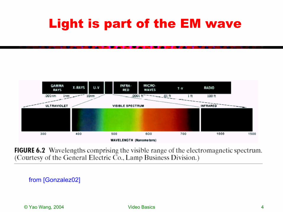
Light is part of the EM wave
from [Gonzalez02]
© Yao Wang, 2004 Video Basics 5
Illuminating and Reflecting Light
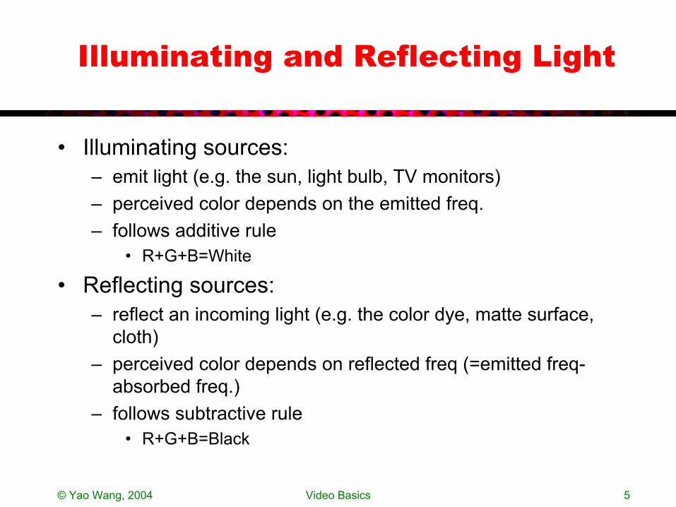
• Illuminating sources: – emit light (e.g. the sun, light bulb, TV monitors)– perceived color depends on the emitted freq. – follows additive rule
• R+G+B=White
• Reflecting sources: – reflect an incoming light (e.g. the color dye, matte surface,
cloth)– perceived color depends on reflected freq (=emitted freq-
absorbed freq.)– follows subtractive rule
• R+G+B=Black
© Yao Wang, 2004 Video Basics 6
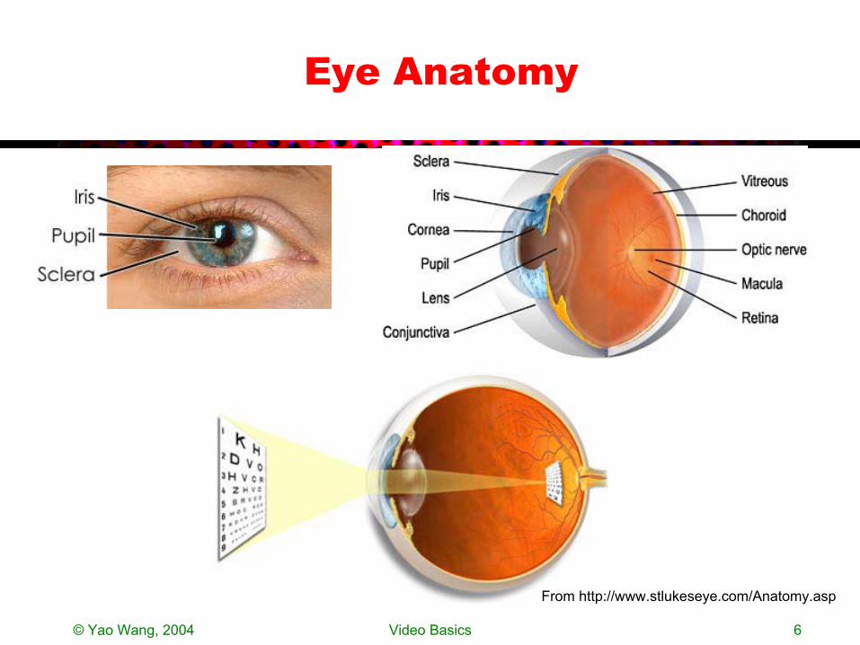
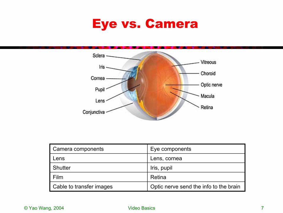
Eye Anatomy
From http://www.stlukeseye.com/Anatomy.asp
© Yao Wang, 2004 Video Basics 7
Eye vs. Camera
Optic nerve send the info to the brainCable to transfer images
RetinaFilm
Iris, pupilShutter
Lens, corneaLens
Eye componentsCamera components
© Yao Wang, 2004 Video Basics 8
Human Perception of Color
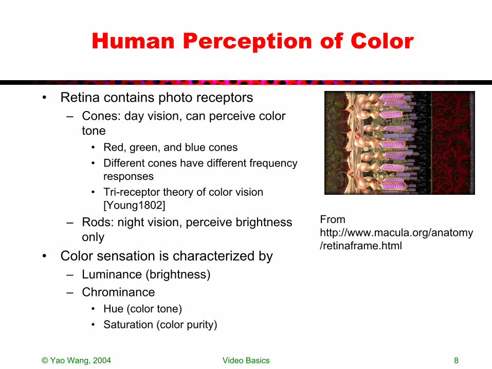
• Retina contains photo receptors– Cones: day vision, can perceive color
tone• Red, green, and blue cones• Different cones have different frequency
responses• Tri-receptor theory of color vision
[Young1802]– Rods: night vision, perceive brightness
only• Color sensation is characterized by
– Luminance (brightness)– Chrominance
• Hue (color tone)• Saturation (color purity)
From http://www.macula.org/anatomy/retinaframe.html
© Yao Wang, 2004 Video Basics 9
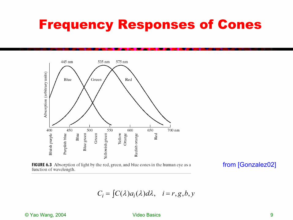
Frequency Responses of Cones
ybgridaCC ii ,,,,)()( == ∫ λλλ
from [Gonzalez02]
© Yao Wang, 2004 Video Basics 10
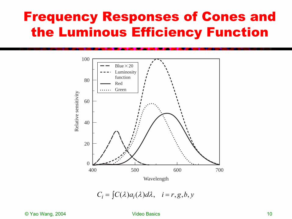
Frequency Responses of Cones and the Luminous Efficiency Function
100
0400 500 600 700
20
40
60
80 R
elat
ive
sens
itivi
ty
Wavelength
LuminosityfunctionRedGreen
Blue�20
ybgridaCC ii ,,,,)()( == ∫ λλλ
© Yao Wang, 2004 Video Basics 11
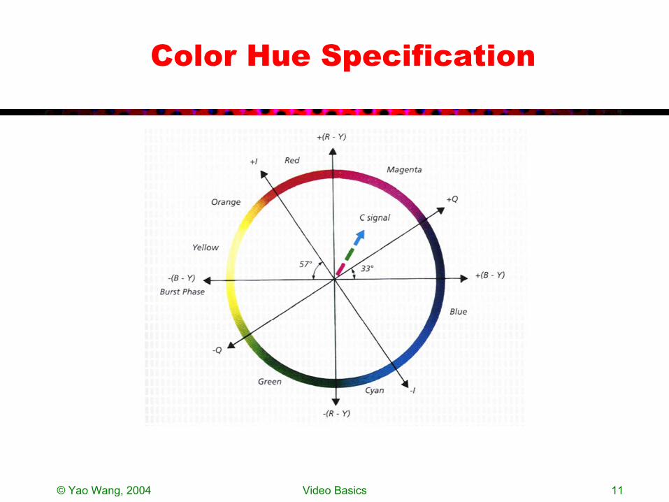
Color Hue Specification
© Yao Wang, 2004 Video Basics 12
Trichromatic Color Mixing
• Trichromatic color mixing theory– Any color can be obtained by mixing three primary colors with a
right proportion
• Primary colors for illuminating sources:– Red, Green, Blue (RGB)– Color monitor works by exciting red, green, blue phosphors using
separate electronic guns• Primary colors for reflecting sources (also known as secondary
colors):– Cyan, Magenta, Yellow (CMY)– Color printer works by using cyan, magenta, yellow and black
(CMYK) dyes
valuessTristimulu :,3,2,1
kk
kk TCTC ∑=
=

© Yao Wang, 2004 Video Basics 13
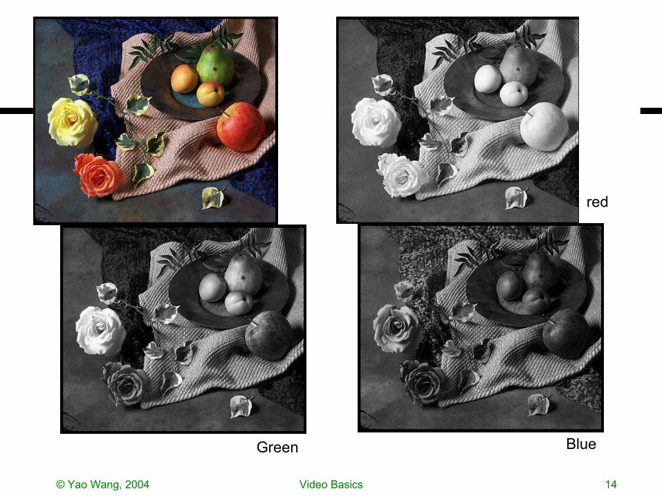
RGB vs CMY
© Yao Wang, 2004 Video Basics 14
red
Green Blue
© Yao Wang, 2004 Video Basics 15
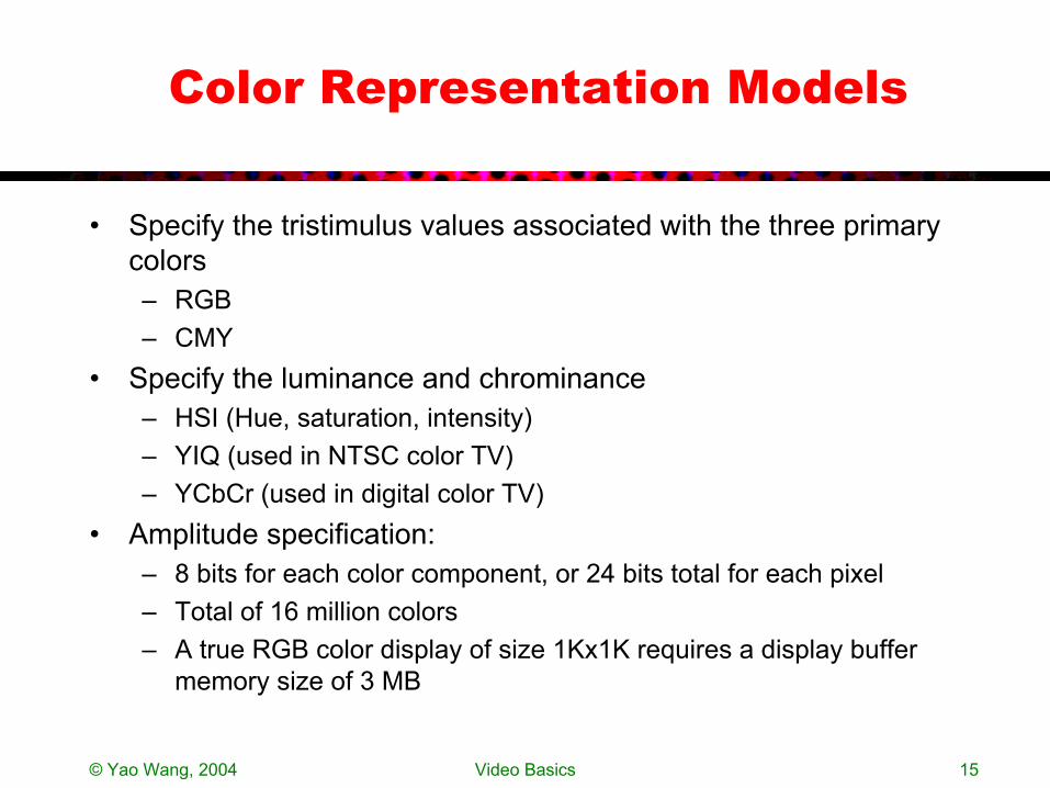
Color Representation Models
• Specify the tristimulus values associated with the three primarycolors– RGB– CMY
• Specify the luminance and chrominance– HSI (Hue, saturation, intensity)– YIQ (used in NTSC color TV)– YCbCr (used in digital color TV)
• Amplitude specification: – 8 bits for each color component, or 24 bits total for each pixel– Total of 16 million colors – A true RGB color display of size 1Kx1K requires a display buffer
memory size of 3 MB
© Yao Wang, 2004 Video Basics 16
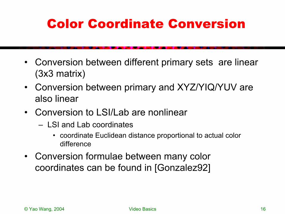
Color Coordinate Conversion
• Conversion between different primary sets are linear (3x3 matrix)
• Conversion between primary and XYZ/YIQ/YUV are also linear
• Conversion to LSI/Lab are nonlinear– LSI and Lab coordinates
• coordinate Euclidean distance proportional to actual color difference
• Conversion formulae between many color coordinates can be found in [Gonzalez92]
© Yao Wang, 2004 Video Basics 17
Video Capture and Display
• Light reflection physics• Imaging operator• Color capture• Color display• Component vs. composite video
© Yao Wang, 2004 Video Basics 18
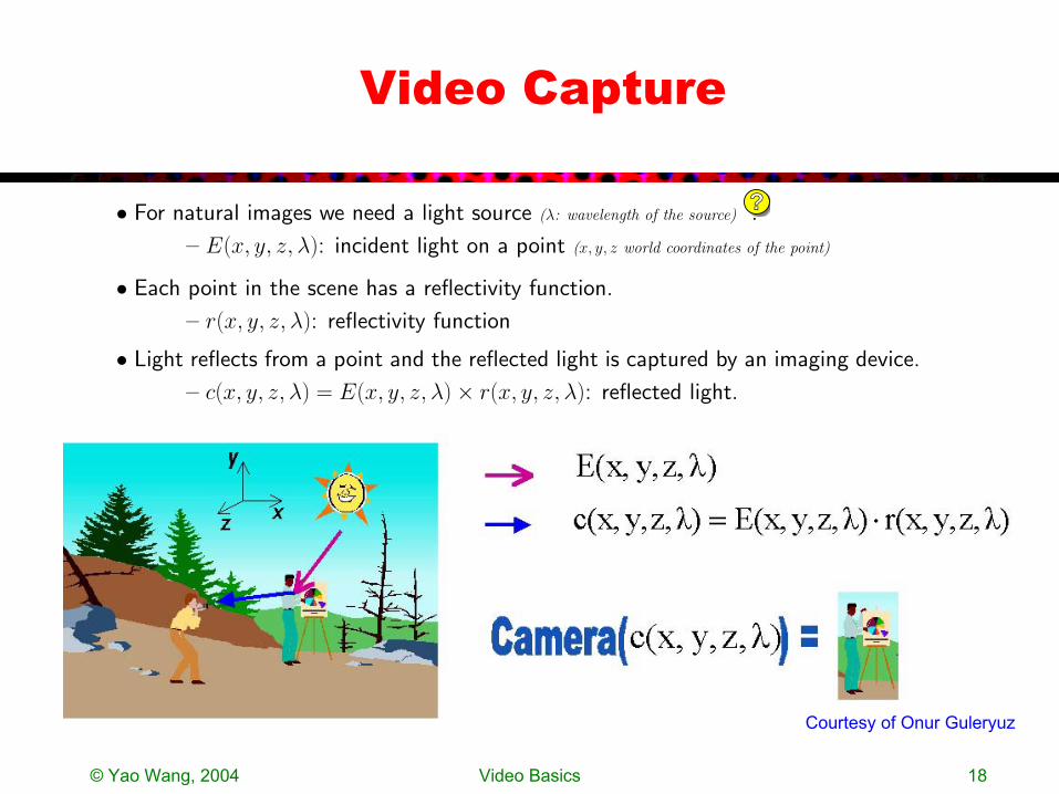
Video Capture
• For natural images we need a light source (λ: wavelength of the source) .
– E(x, y, z, λ): incident light on a point (x, y, z world coordinates of the point)
• Each point in the scene has a reflectivity function.
– r(x, y, z, λ): reflectivity function
• Light reflects from a point and the reflected light is captured by an imaging device.
– c(x, y, z, λ) = E(x, y, z, λ) × r(x, y, z, λ): reflected light.
?
Courtesy of Onur Guleryuz

© Yao Wang, 2004 Video Basics 19
More on Video Capture
• Reflected light to camera– Camera absorption function
– Projection from 3-D to 2-D
• The projection operator is non-linear – Perspective projection– Othographic projection
λλλψ datCt c )(),,(),( ∫= XX
)),((),(or ),()),(( 1 tPtttPP
xxXX
xX−==
→
ψψψψ

© Yao Wang, 2004 Video Basics 20
Perspective Projection Model
Y
Y
X
Z
C
X
X
x
x
y
x
y
F
Z
Cameracenter
Imageplane
2-Dimage
3-Dpoint
The image of an object is reversed from its 3-D position. The object appears smaller when it is farther away.
ZYFy
ZXFx == ,
© Yao Wang, 2004 Video Basics 21
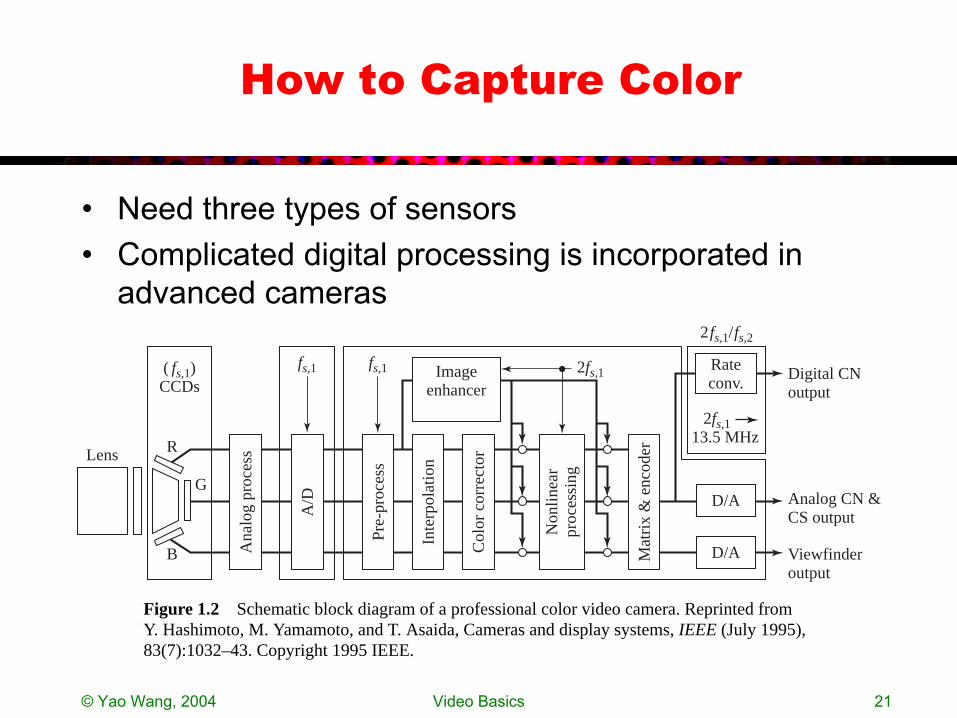
How to Capture Color
• Need three types of sensors• Complicated digital processing is incorporated in
advanced cameras
Inte
rpol
atio
n
Non
linea
rpr
oces
sing
A/D
RLens
B
G
( fs,1)CCDs
fs,1 fs,1 2fs,1
2fs,1/fs,2
Imageenhancer
D/A
D/A
Rateconv.
Digital CNoutput
Analog CN &CS output
Viewfinderoutput
2fs,1 13.5 MHz
Pre-
proc
ess
Ana
log
proc
ess
Col
or c
orre
ctor
Mat
rix
& e
ncod
er
Figure 1.2 Schematic block diagram of a professional color video camera. Reprinted fromY. Hashimoto, M. Yamamoto, and T. Asaida, Cameras and display systems, IEEE (July 1995),83(7):1032–43. Copyright 1995 IEEE.
© Yao Wang, 2004 Video Basics 22
Video Display
• CRT vs LCD• Need three light sources projecting red, green, blue
components respectively
© Yao Wang, 2004 Video Basics 23
Analog Video
• Video raster• Progressive vs. interlaced raster• Analog TV systems
© Yao Wang, 2004 Video Basics 24
Raster Scan
• Real-world scene is a continuous 3-D signal (temporal, horizontal, vertical)
• Analog video is stored in the raster format– Sampling in time: consecutive sets of frames
• To render motion properly, >=30 frame/s is needed– Sampling in vertical direction: a frame is represented by a
set of scan lines• Number of lines depends on maximum vertical frequency and
viewing distance, 525 lines in the NTSC system– Video-raster = 1-D signal consisting of scan lines from
successive frames
© Yao Wang, 2004 Video Basics 25
Progressive and Interlaced Scans
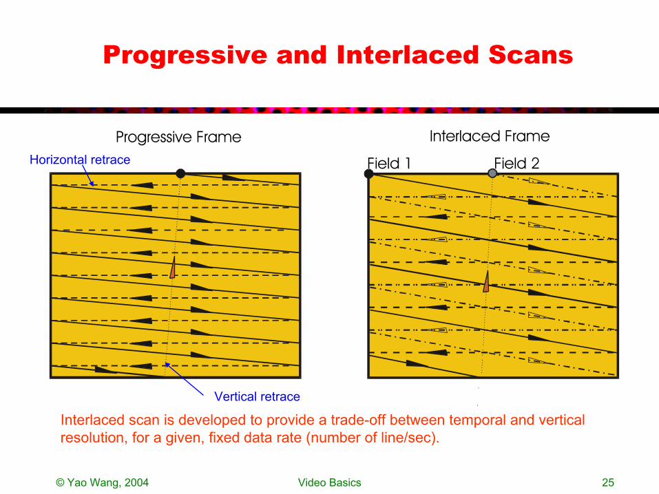
Field 1 Field 2
Progressive Frame Interlaced Frame
Interlaced scan is developed to provide a trade-off between temporal and vertical resolution, for a given, fixed data rate (number of line/sec).
Horizontal retrace
Vertical retrace
© Yao Wang, 2004 Video Basics 26
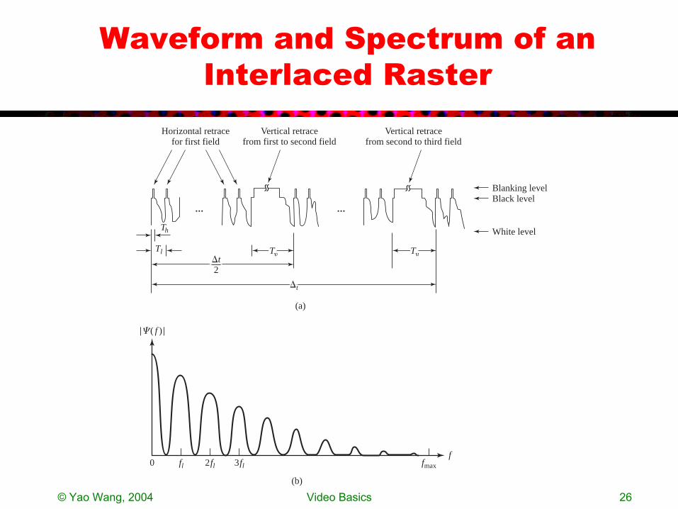
Waveform and Spectrum of an Interlaced Raster
0 fl 2fl 3fl fmax
f
��( f )�
(b)
(a)
Tl
Th
T�
�t
�t2
T�
Horizontal retracefor first field
Vertical retracefrom first to second field
Vertical retracefrom second to third field
Blanking levelBlack level
White level
��

© Yao Wang, 2004 Video Basics 27
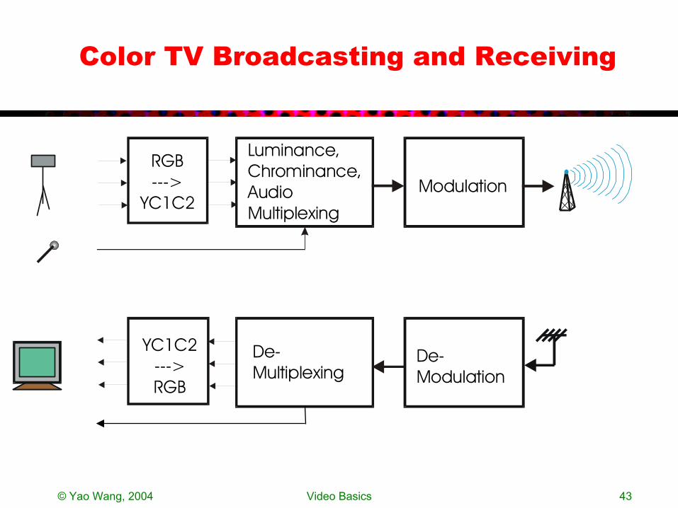
Color TV Broadcasting and Receiving
Luminance,Chrominance,Audio Multiplexing
Modulation
De-Modulation
De-Multiplexing
YC1C2--->RGB
RGB--->
YC1C2
© Yao Wang, 2004 Video Basics 28
Why not using RGB directly?
• R,G,B components are correlated– Transmitting R,G,B components separately is redundant– More efficient use of bandwidth is desired
• RGB->YC1C2 transformation– Decorrelating: Y,C1,C2 are uncorrelated– C1 and C2 require lower bandwidth– Y (luminance) component can be received by B/W TV sets
• YIQ in NTSC– I: orange-to-cyan– Q: green-to-purple (human eye is less sensitive)
• Q can be further bandlimited than I– Phase=Arctan(Q/I) = hue, Magnitude=sqrt (I^2+Q^2) = saturation– Hue is better retained than saturation
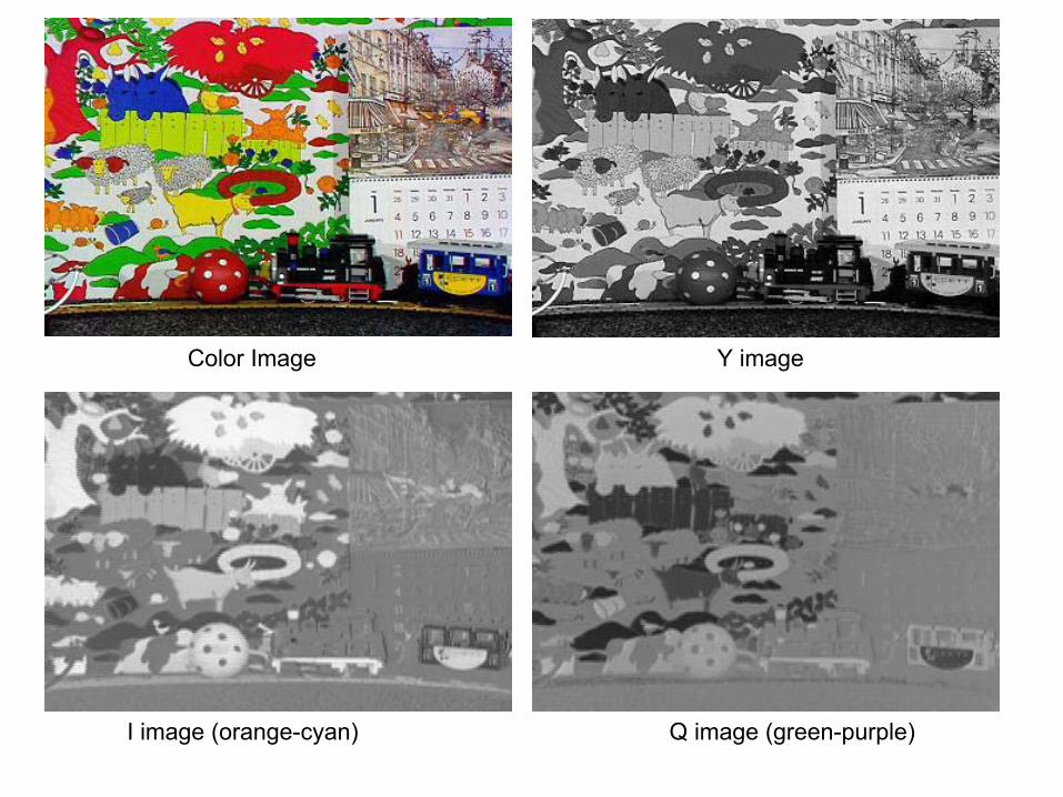
Color Image Y image
I image (orange-cyan) Q image (green-purple)
© Yao Wang, 2004 Video Basics 30
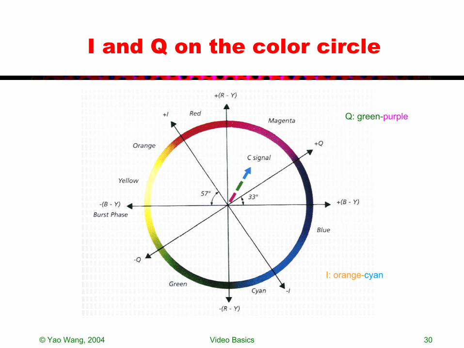
I and Q on the color circle
I: orange-cyan
Q: green-purple
© Yao Wang, 2004 Video Basics 31
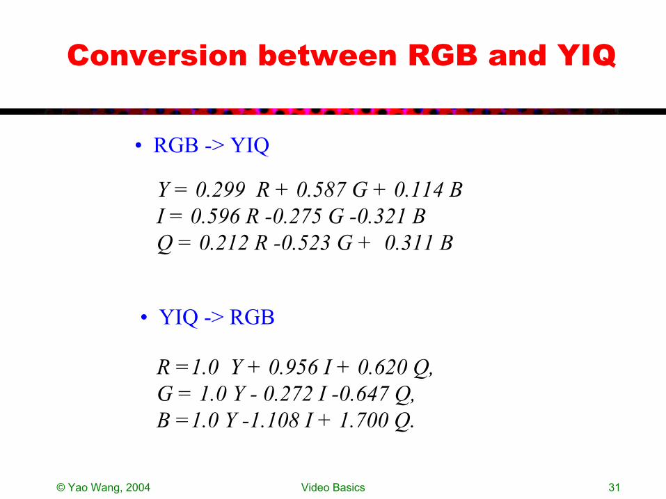
Conversion between RGB and YIQ
Y = 0.299 R + 0.587 G + 0.114 BI = 0.596 R -0.275 G -0.321 BQ = 0.212 R -0.523 G + 0.311 B
R =1.0 Y + 0.956 I + 0.620 Q,G = 1.0 Y - 0.272 I -0.647 Q,B =1.0 Y -1.108 I + 1.700 Q.
• RGB -> YIQ
• YIQ -> RGB
© Yao Wang, 2004 Video Basics 32
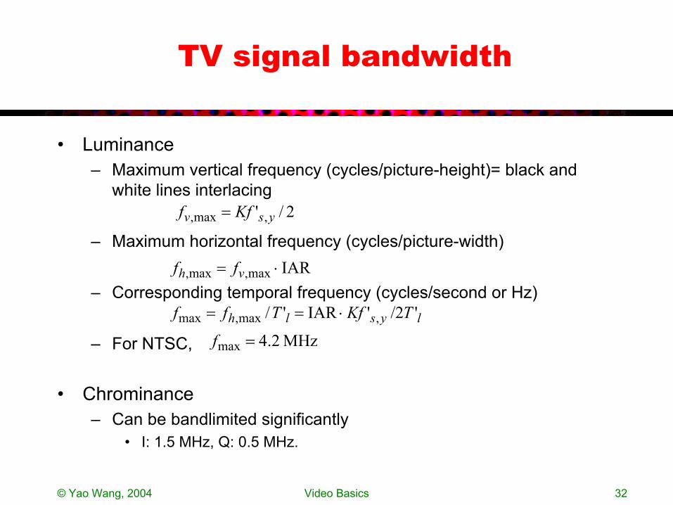
TV signal bandwidth
• Luminance– Maximum vertical frequency (cycles/picture-height)= black and
white lines interlacing
– Maximum horizontal frequency (cycles/picture-width)
– Corresponding temporal frequency (cycles/second or Hz)
– For NTSC,
• Chrominance– Can be bandlimited significantly
• I: 1.5 MHz, Q: 0.5 MHz.
2/' ,max, ysv Kff =
IARmax,max, ⋅= vh ff
lyslh TKfTff '/2'IAR'/ ,max,max ⋅==
MHz2.4max =f
© Yao Wang, 2004 Video Basics 33
Bandwidth of Chrominance Signals
• Theoretically, for the same line rate, the chromiance signal can have as high frequency as the luminance signal
• However, with real video signals, the chrominance component typically changes much slower than luminance
• Furthermore, the human eye is less sensitive to changes in chrominance than to changes in luminance
• The eye is more sensitive to the orange-cyan range (I) (the color of face!) than to green-purple range (Q)
• The above factors lead to – I: bandlimitted to 1.5 MHz– Q: bandlimitted to 0.5 MHz
© Yao Wang, 2004 Video Basics 34
Multiplexing of Luminance and Chrominance
• Chrominance signal can be bandlimited – it usually has a narrower frequency span than the luminance and
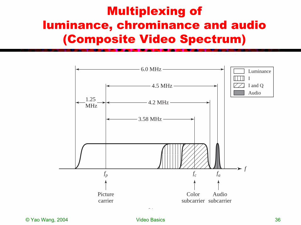
the human eye is less sensitive to high frequencies in chrominance• The two chrominance components (I and Q) are multiplexed
onto the same sub-carrier using QAM– The upper band of I is limited to 0.5 MHz to avoid interference with
audio• Position the bandlimited chrominance at the high end spectrum
of the luminance, where the luminance is weak, but still sufficiently lower than the audio (at 4.5 MHz=286 fl)
• The actual position should be such that the peaks of chrominance spectrum interlace with those of the luminance
NTSC)for Hz 58.3( 2/455 == lc ff

© Yao Wang, 2004 Video Basics 35
Spectrum Illustration
ChrominanceLuminance
0 fl 2fl 3fl 225fl 226fl 227fl 228fl
fc(Color subcarrier)
229fl 230flf
�( f )
© Yao Wang, 2004 Video Basics 36
Multiplexing of luminance, chrominance and audio
(Composite Video Spectrum)
(b)
f
Picturecarrier
fp
Colorsubcarrier
fc
Audiosubcarrier
fa
6.0 MHz
4.5 MHz
4.2 MHz1.25 MHz
3.58 MHz
Luminance
I
I and Q
Audio
© Yao Wang, 2004 Video Basics 37
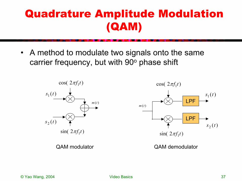
Quadrature Amplitude Modulation (QAM)
• A method to modulate two signals onto the same carrier frequency, but with 90o phase shift
)2cos( 1tfπ
)2sin( 1tfπ
)(1 ts
)(2 ts
)(tmLPF
LPF
)2cos( 1tfπ
)2sin( 1tfπ
)(1 ts
)(2 ts
)(tm
QAM modulator QAM demodulator

© Yao Wang, 2004 Video Basics 38
Adding Color Bursts for Synchronization
Figure from From Grob, Basic Color Television Principles and Servicing, McGraw Hill, 1975http://www.ee.washington.edu/conselec/CE/kuhn/ntsc/95x417.gif
For accurate regeneration of the color sub-carrier signal at the receiver, a color burst signal is added during the horizontal retrace period
© Yao Wang, 2004 Video Basics 39
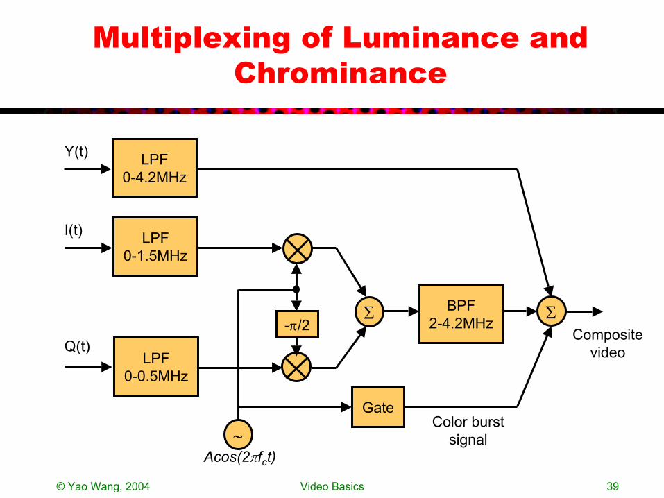
Multiplexing of Luminance and Chrominance
Composite video
LPF0-4.2MHz
BPF2-4.2MHz
LPF0-1.5MHz
-π/2Σ
LPF0-0.5MHz
Σ
∼Acos(2πfct)
Gate
Y(t)
I(t)
Q(t)
Color burst signal
© Yao Wang, 2004 Video Basics 40
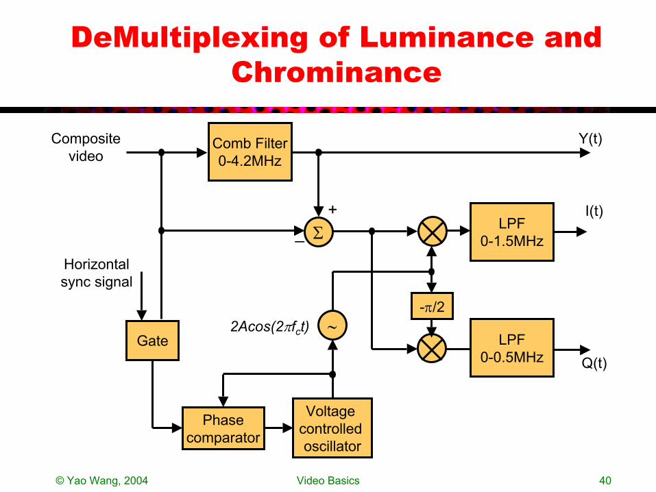
DeMultiplexing of Luminance and Chrominance
Composite video
Comb Filter0-4.2MHz
LPF0-1.5MHz
-π/2
LPF0-0.5MHz
∼2Acos(2πfct)Gate
Y(t)
I(t)
Q(t)
Σ
Phasecomparator
Voltage controlled oscillator
Horizontalsync signal
_+
© Yao Wang, 2004 Video Basics 41
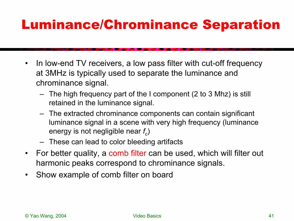
Luminance/Chrominance Separation
• In low-end TV receivers, a low pass filter with cut-off frequency at 3MHz is typically used to separate the luminance and chrominance signal. – The high frequency part of the I component (2 to 3 Mhz) is still
retained in the luminance signal. – The extracted chrominance components can contain significant
luminance signal in a scene with very high frequency (luminance energy is not negligible near fc)
– These can lead to color bleeding artifacts • For better quality, a comb filter can be used, which will filter out
harmonic peaks correspond to chrominance signals.• Show example of comb filter on board

© Yao Wang, 2004 Video Basics 42
What will a Monochrome TV see?
• The monochrome TV receiver uses a LPT with cut-off at 4.2 MHz, and thus will get the composite video (baseband luminance plus the I and Q signal modulated to fc =3.58 MHz)– Because the modulated chrominance signal is at very high
frequency (227.5 cycles per line), the eye smoothes it out mostly, but there can be artifacts
– The LPF in Practical TV receivers have wide transition bands, and the response is already quite low at fc.
© Yao Wang, 2004 Video Basics 43
Color TV Broadcasting and Receiving
Luminance,Chrominance,Audio Multiplexing
Modulation
De-Modulation
De-Multiplexing
YC1C2--->RGB
RGB--->
YC1C2
© Yao Wang, 2004 Video Basics 44
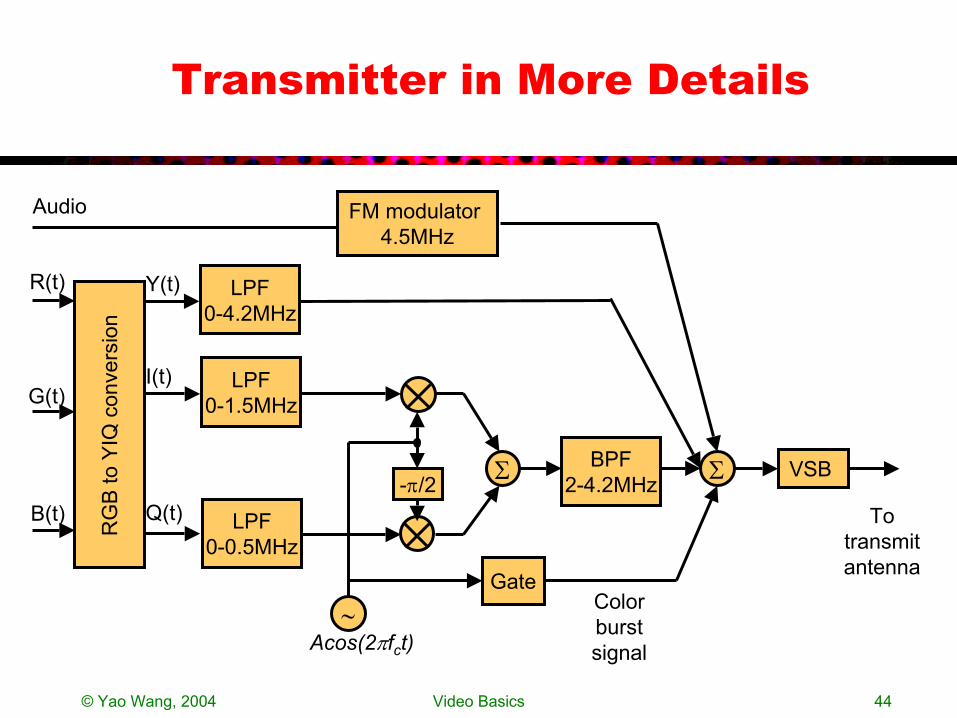
Transmitter in More Details
LPF0-4.2MHz
BPF2-4.2MHz
LPF0-1.5MHz
-π/2 Σ
LPF0-0.5MHz
Σ
∼Acos(2πfct)
Gate
Y(t)
I(t)
Q(t)
Color burst signal
RG
B to
YIQ
con
vers
ion
R(t)
G(t)
B(t)
FM modulator 4.5MHz
Audio
VSB
To transmit antenna
© Yao Wang, 2004 Video Basics 45
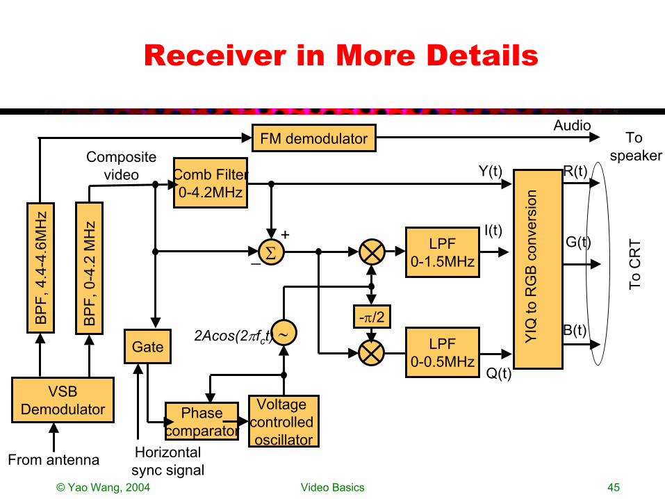
Receiver in More Details
Composite video Comb Filter
0-4.2MHz
LPF0-1.5MHz
-π/2
LPF0-0.5MHz
∼2Acos(2πfct)Gate
Y(t)
I(t)
Q(t)
Σ
Phasecomparator
Voltage controlled oscillator
Horizontalsync signal
_+
R(t)
G(t)
B(t)YIQ
to R
GB
con
vers
ion
VSBDemodulator
BP
F, 0
-4.2
MH
z
BP
F, 4
.4-4
.6M
Hz
FM demodulatorAudio
From antenna
To C
RT
To speaker
© Yao Wang, 2004 Video Basics 46
Matlab Simulation of Mux/Demux
• We will show the multiplexing/demultiplexing of YIQ process for a real sequence (‘mobile calendar’)– Original Y,I, Q frames– Converted Y,I, Q raster signals and their respective
spectrums– QAM of I and Q: choice of fc, waveform and spectrum– Multiplexing of Y and QAM(I+Q): waveform and spectrum– What wil a B/W TV receiver see:
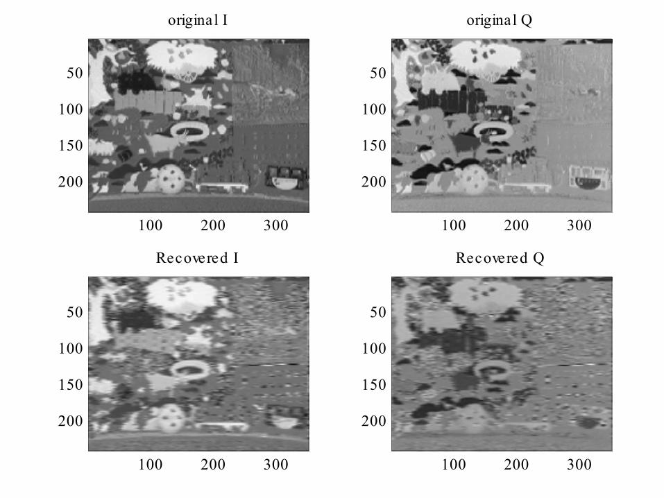
• W/o filtering vs. with filtering– What will a color TV receiver see:
• Original and recovered Y,I, Q • Original and recovered color image• Spectrum and waveforms

© Yao Wang, 2004 Video Basics 47
Spectrum of Y, I, Q
0 5 10
x 105
10-1
100
101
102
103
104
105
106
Y S pectrum
0 5 10
x 105
10-1
100
101
102
103
104
105
106
I S pectrum
0 5 10
x 105
10-1
100
101
102
103
104
105
106
Q S pectrum
Spectrum of Y, I, and Q components, computed from first two progressive frames of “mobilcal”, 352x240/frame
Maximum possible frequency is 352x240x30/2=1.26 MHz.
Notice bandwidths of Y, I, Q components are 0.8,0.2,0.15 MHz, respectively, if we consider 10^3 as the cut-off magnitude.
© Yao Wang, 2004 Video Basics 48
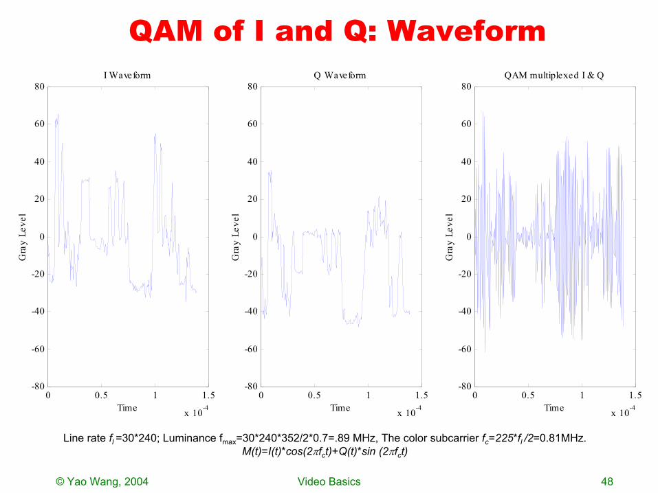
QAM of I and Q: Waveform
Line rate fl =30*240; Luminance fmax=30*240*352/2*0.7=.89 MHz, The color subcarrier fc=225*fl /2=0.81MHz.M(t)=I(t)*cos(2πfct)+Q(t)*sin (2πfct)
0 0.5 1 1.5
x 10-4
-80
-60
-40
-20
0
20
40
60
80
Gra
y Le
vel
Time
QAM multiplexed I & Q
0 0.5 1 1.5
x 10-4
-80
-60
-40
-20
0
20
40
60
80
Gra
y Le
vel
Time
I Waveform
0 0.5 1 1.5
x 10-4
-80
-60
-40
-20
0
20
40
60
80
Gra
y Le
vel
Time
Q Waveform
© Yao Wang, 2004 Video Basics 49
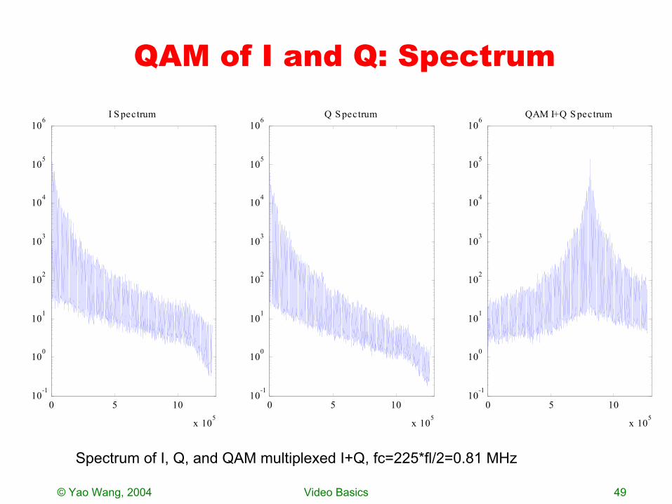
QAM of I and Q: Spectrum
0 5 10
x 105
10-1
100
101
102
103
104
105
106I S pectrum
0 5 10
x 105
10-1
100
101
102
103
104
105
106QAM I+Q S pectrum
0 5 10
x 105
10-1
100
101
102
103
104
105
106Q S pectrum
Spectrum of I, Q, and QAM multiplexed I+Q, fc=225*fl/2=0.81 MHz
© Yao Wang, 2004 Video Basics 50
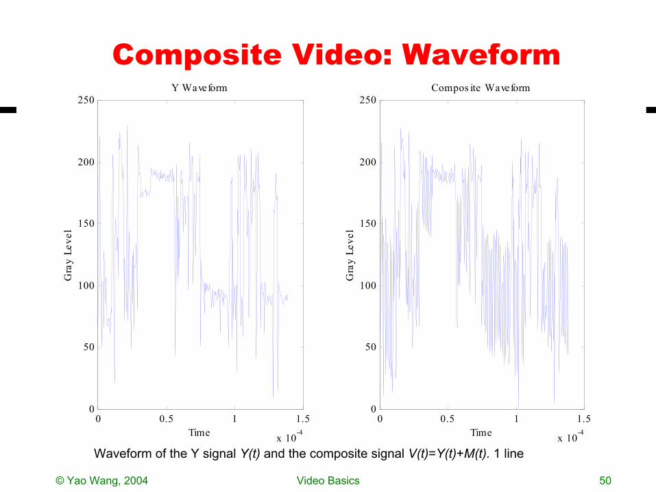
Composite Video: Waveform
0 0.5 1 1.5
x 10-4
0
50
100
150
200
250
Gra
y Le
vel
Time
Y Waveform
0 0.5 1 1.5
x 10-4
0
50
100
150
200
250
Gra
y Le
vel
Time
Compos ite Waveform
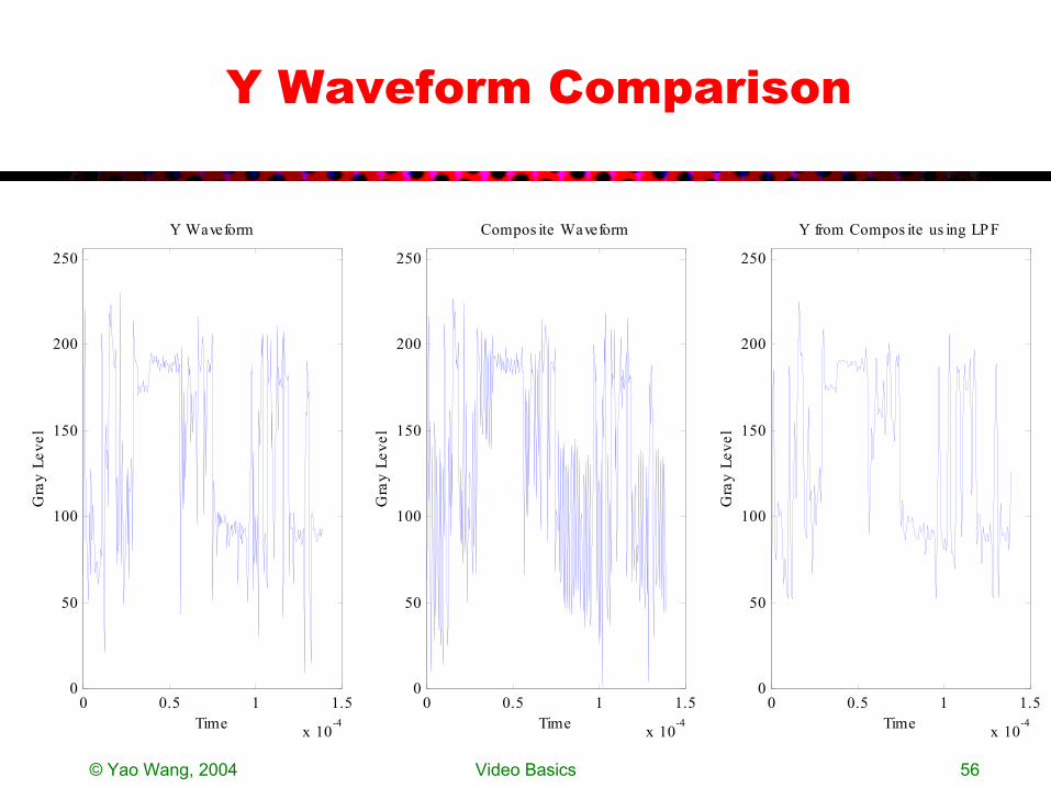
Waveform of the Y signal Y(t) and the composite signal V(t)=Y(t)+M(t). 1 line
© Yao Wang, 2004 Video Basics 51
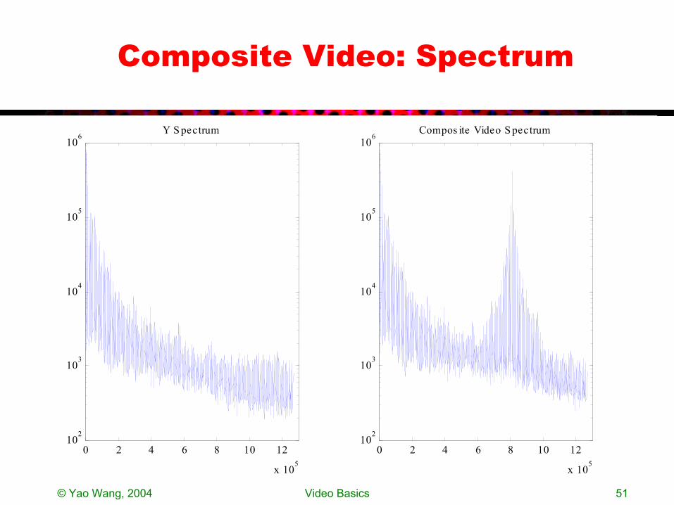
Composite Video: Spectrum
0 2 4 6 8 10 12
x 105
102
103
104
105
106
Y S pectrum
0 2 4 6 8 10 12
x 105
102
103
104
105
106
Compos ite Video S pectrum
© Yao Wang, 2004 Video Basics 52
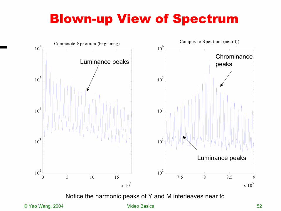
Blown-up View of Spectrum
Notice the harmonic peaks of Y and M interleaves near fc
0 5 10 15
x 104
102
103
104
105
106
Compos ite S pectrum (beginning)
7.5 8 8.5 9
x 105
102
103
104
105
106
Compos ite S pectrum (near fc)
Luminance peaksChrominancepeaks
Luminance peaks
© Yao Wang, 2004 Video Basics 53
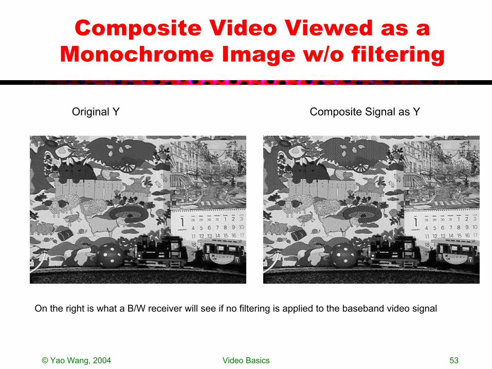
Composite Video Viewed as a Monochrome Image w/o filtering
Original Y Composite Signal as Y
On the right is what a B/W receiver will see if no filtering is applied to the baseband video signal
© Yao Wang, 2004 Video Basics 54
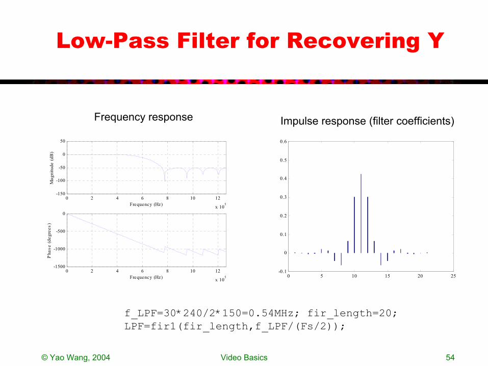
Low-Pass Filter for Recovering Y
0 2 4 6 8 10 12
x 105
-150
-100
-50
0
50
Frequency (Hz)
Mag
nitu
de (d
B)
0 2 4 6 8 10 12
x 105
-1500
-1000
-500
0
Frequency (Hz)
Pha
se (d
egre
es)
f_LPF=30*240/2*150=0.54MHz; fir_length=20;LPF=fir1(fir_length,f_LPF/(Fs/2));
Frequency response Impulse response (filter coefficients)
0 5 10 15 20 25-0.1
0
0.1
0.2
0.3
0.4
0.5
0.6
© Yao Wang, 2004 Video Basics 55
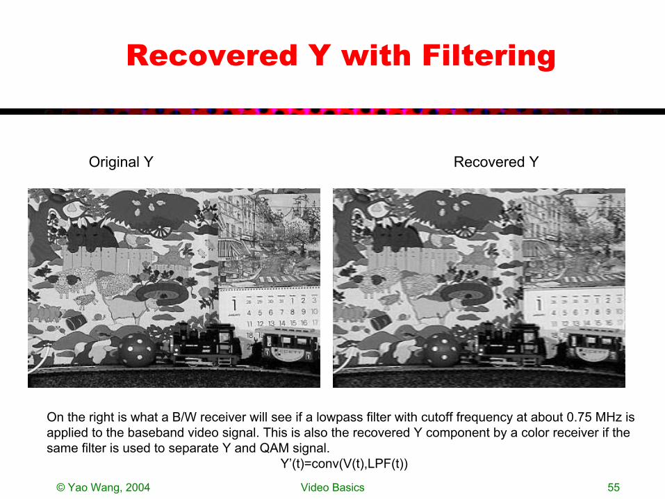
Recovered Y with Filtering
Original Y
On the right is what a B/W receiver will see if a lowpass filter with cutoff frequency at about 0.75 MHz is applied to the baseband video signal. This is also the recovered Y component by a color receiver if the same filter is used to separate Y and QAM signal.
Y’(t)=conv(V(t),LPF(t))
Recovered Y
© Yao Wang, 2004 Video Basics 56
Y Waveform Comparison
0 0.5 1 1.5
x 10-4
0
50
100
150
200
250
Gra
y Le
vel
Time
Y Waveform
0 0.5 1 1.5
x 10-4
0
50
100
150
200
250
Gra
y Le
vel
Time
Compos ite Waveform
0 0.5 1 1.5
x 10-4
0
50
100
150
200
250
Gra
y Le
vel
Time
Y from Compos ite us ing LP F

© Yao Wang, 2004 Video Basics 57
Demux Y and QAM(I,Q)
0 0.5 1 1.5
x 10-4
-80
-60
-40
-20
0
20
40
60
80
Gra
y Le
vel
Time
QAM Waveform
0 0.5 1 1.5
x 10-4
-80
-60
-40
-20
0
20
40
60
80
Gra
y Le
vel
Time
Demultiplexed QAM
M’(t)=V(t)-Y’(t)
© Yao Wang, 2004 Video Basics 58
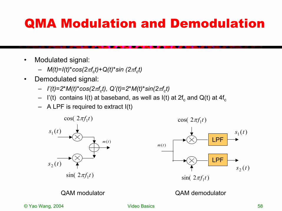
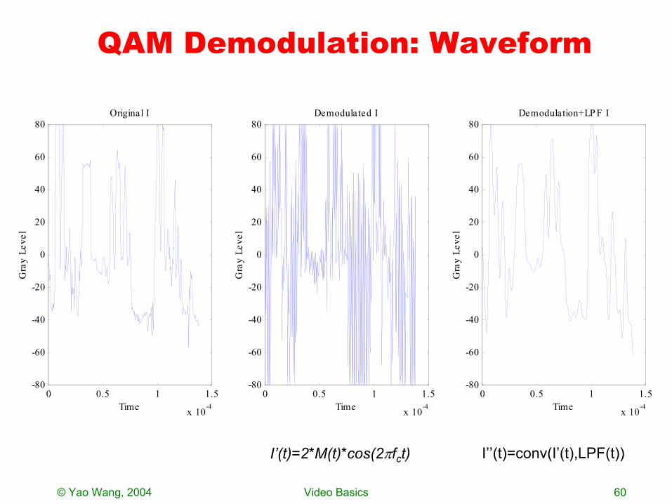
QMA Modulation and Demodulation
• Modulated signal:– M(t)=I(t)*cos(2πfct)+Q(t)*sin (2πfct)
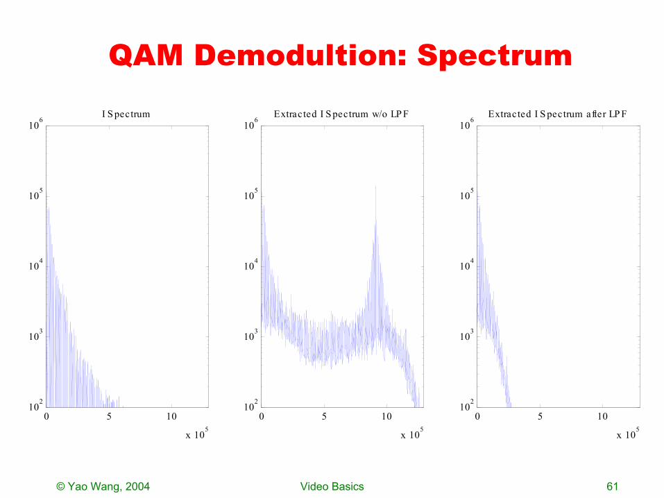
• Demodulated signal: – I’(t)=2*M(t)*cos(2πfct), Q’(t)=2*M(t)*sin(2πfct)– I’(t) contains I(t) at baseband, as well as I(t) at 2fc and Q(t) at 4fc– A LPF is required to extract I(t)
)2cos( 1tfπ
)2sin( 1tfπ
)(1 ts
)(2 ts
)(tmLPF
LPF
)2cos( 1tfπ
)2sin( 1tfπ
)(1 ts
)(2 ts
)(tm
QAM modulator QAM demodulator
© Yao Wang, 2004 Video Basics 59
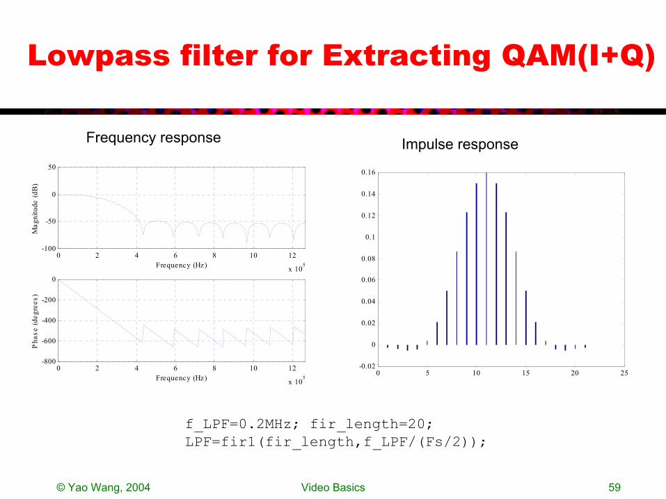
Lowpass filter for Extracting QAM(I+Q)
0 2 4 6 8 10 12
x 105
-100
-50
0
50
Frequency (Hz)
Mag
nitu
de (d
B)
0 2 4 6 8 10 12
x 105
-800
-600
-400
-200
0
Frequency (Hz)
Pha
se (d
egre
es)
f_LPF=0.2MHz; fir_length=20;LPF=fir1(fir_length,f_LPF/(Fs/2));
0 5 10 15 20 25-0.02
0
0.02
0.04
0.06
0.08
0.1
0.12
0.14
0.16
Frequency response Impulse response
© Yao Wang, 2004 Video Basics 60
QAM Demodulation: Waveform
I’(t)=2*M(t)*cos(2πfct) I’’(t)=conv(I’(t),LPF(t))
0 0.5 1 1.5
x 10-4
-80
-60
-40
-20
0
20
40
60
80
Gra
y Le
vel
Time
Original I
0 0.5 1 1.5
x 10-4
-80
-60
-40
-20
0
20
40
60
80
Gra
y Le
vel
Time
Demodulated I
0 0.5 1 1.5
x 10-4
-80
-60
-40
-20
0
20
40
60
80
Gra
y Le
vel
Time
Demodulation+LP F I
© Yao Wang, 2004 Video Basics 61
QAM Demodultion: Spectrum
0 5 10
x 105
102
103
104
105
106
I S pectrum
0 5 10
x 105
102
103
104
105
106
Extracted I S pectrum w/o LP F
0 5 10
x 105
102
103
104
105
106
Extracted I S pectrum after LP F
© Yao Wang, 2004 Video Basics 62
original I
100 200 300
50
100
150
200
original Q
100 200 300
50
100
150
200
Recovered I
100 200 300
50
100
150
200
Recovered Q
100 200 300
50
100
150
200

© Yao Wang, 2004 Video Basics 63
Original color frame
Recovered color frame
© Yao Wang, 2004 Video Basics 64
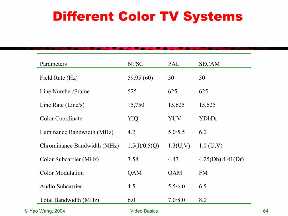
Different Color TV Systems
Parameters NTSC PAL SECAM
Field Rate (Hz) 59.95 (60) 50 50
Line Number/Frame 525 625 625
Line Rate (Line/s) 15,750 15,625 15,625
Color Coordinate YIQ YUV YDbDr
Luminance Bandwidth (MHz) 4.2 5.0/5.5 6.0
Chrominance Bandwidth (MHz) 1.5(I)/0.5(Q) 1.3(U,V) 1.0 (U,V)
Color Subcarrier (MHz) 3.58 4.43 4.25(Db),4.41(Dr)
Color Modulation QAM QAM FM
Audio Subcarrier 4.5 5.5/6.0 6.5
Total Bandwidth (MHz) 6.0 7.0/8.0 8.0
© Yao Wang, 2004 Video Basics 65
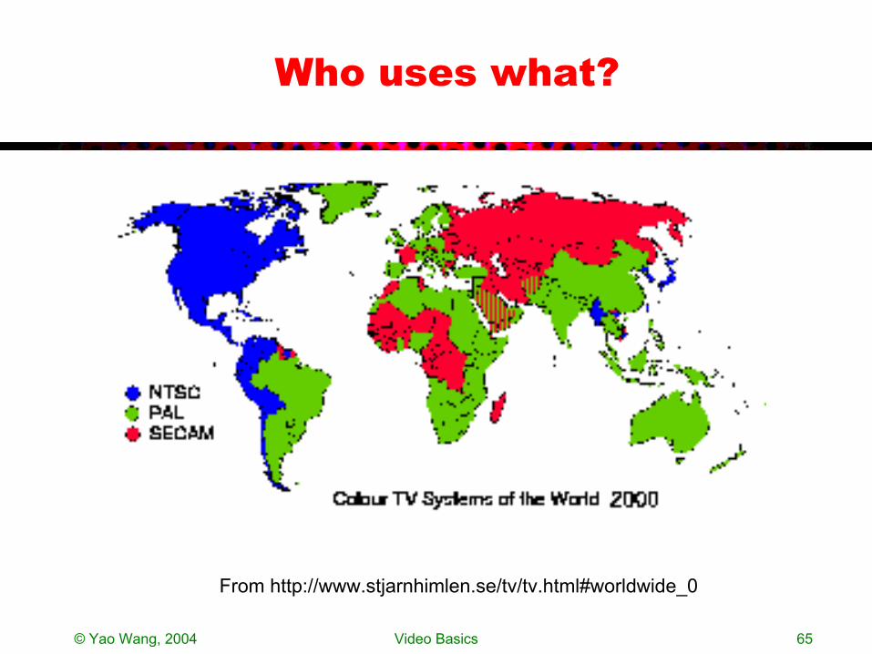
Who uses what?
From http://www.stjarnhimlen.se/tv/tv.html#worldwide_0
© Yao Wang, 2004 Video Basics 66
Digital Video
• Digital video by sampling/quantizing analog video raster BT.601 video
• Other digital video formats and their applications
© Yao Wang, 2004 Video Basics 67
Digitizing A Raster Video
• Sample the raster waveform = Sample along the horizontal direction
• Sampling rate must be chosen properly– For the samples to be aligned vertically, the sampling rate should
be multiples of the line rate– Horizontal sampling interval = vertical sampling interval– Total sampling rate equal among different systems
MHz 5.13)(PAL/SECAM864(NTSC)858 === lls fff
© Yao Wang, 2004 Video Basics 68
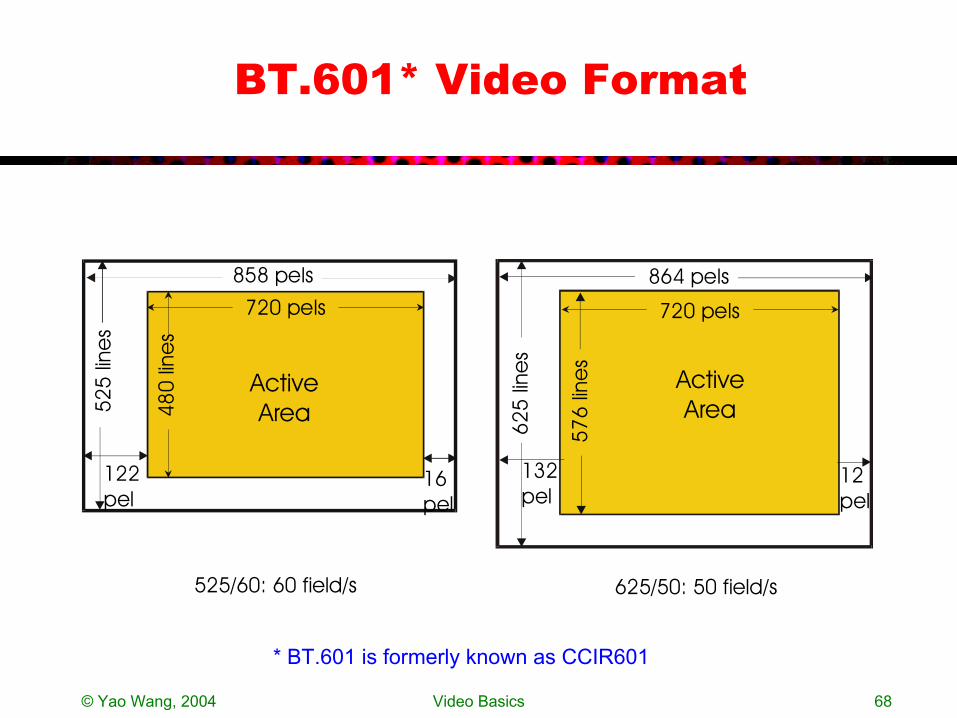
BT.601* Video Format
480
lines
525
line
s
122pel
16pel
858 pels
720 pels
ActiveArea
525/60: 60 field/s57
6 lin
es
625
line
s
864 pels
132pel
12pel
720 pels
ActiveArea
625/50: 50 field/s
* BT.601 is formerly known as CCIR601
© Yao Wang, 2004 Video Basics 69
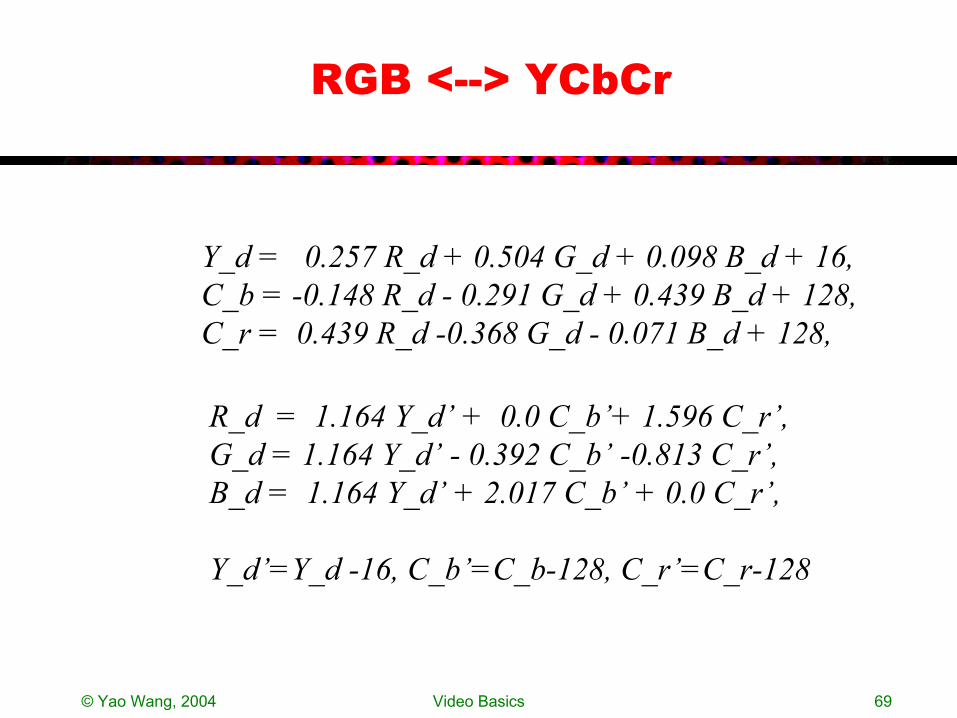
RGB <--> YCbCr
Y_d = 0.257 R_d + 0.504 G_d + 0.098 B_d + 16,C_b = -0.148 R_d - 0.291 G_d + 0.439 B_d + 128,C_r = 0.439 R_d -0.368 G_d - 0.071 B_d + 128,
R_d = 1.164 Y_d’ + 0.0 C_b’+ 1.596 C_r’,G_d = 1.164 Y_d’ - 0.392 C_b’ -0.813 C_r’,B_d = 1.164 Y_d’ + 2.017 C_b’ + 0.0 C_r’,
Y_d’=Y_d -16, C_b’=C_b-128, C_r’=C_r-128
© Yao Wang, 2004 Video Basics 70
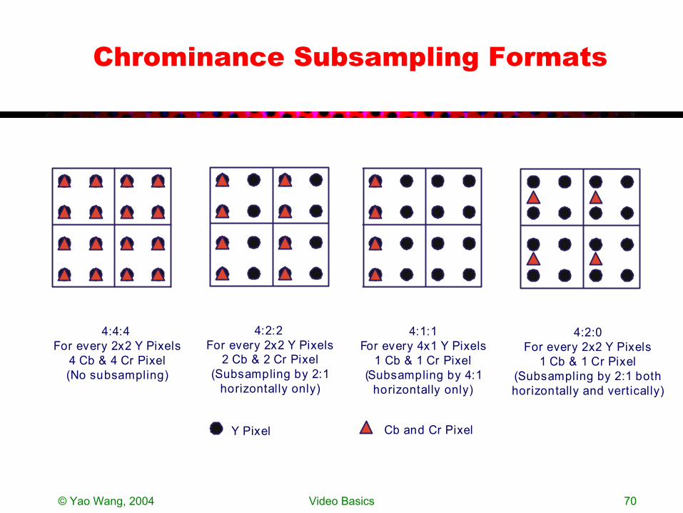
Chrominance Subsampling Formats
4:2:0For every 2x2 Y Pixels
1 Cb & 1 Cr Pixel(Subsampling by 2:1 bothhorizontally and vertically)
4:2:2 For every 2x2 Y Pixels
2 Cb & 2 Cr Pixel(Subsampling by 2:1
horizontally only)
4:4:4 For every 2x2 Y Pixels
4 Cb & 4 Cr Pixel(No subsampling)
Y Pixel Cb and Cr Pixel
4:1:1For every 4x1 Y Pixels
1 Cb & 1 Cr Pixel(Subsampling by 4:1
horizontally only)
© Yao Wang, 2004 Video Basics 71
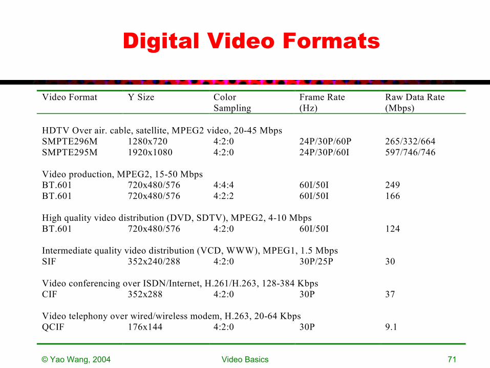
Digital Video Formats
Video Format Y Size Color Sampling
Frame Rate (Hz)
Raw Data Rate (Mbps)
HDTV Over air. cable, satellite, MPEG2 video, 20-45 Mbps SMPTE296M 1280x720 4:2:0 24P/30P/60P 265/332/664 SMPTE295M 1920x1080 4:2:0 24P/30P/60I 597/746/746 Video production, MPEG2, 15-50 Mbps BT.601 720x480/576 4:4:4 60I/50I 249 BT.601 720x480/576 4:2:2 60I/50I 166 High quality video distribution (DVD, SDTV), MPEG2, 4-10 Mbps BT.601 720x480/576 4:2:0 60I/50I 124 Intermediate quality video distribution (VCD, WWW), MPEG1, 1.5 Mbps SIF 352x240/288 4:2:0 30P/25P 30 Video conferencing over ISDN/Internet, H.261/H.263, 128-384 Kbps CIF 352x288 4:2:0 30P 37 Video telephony over wired/wireless modem, H.263, 20-64 Kbps QCIF 176x144 4:2:0 30P 9.1
© Yao Wang, 2004 Video Basics 72
Video Terminology
• Component video– Three color components stored/transmitted separately – Use either RGB or YIQ (YUV) coordinate– New digital video format (YCrCb)– Betacam (professional tape recorder) use this format
• Composite video– Convert RGB to YIQ (YUV)– Multiplexing YIQ into a single signal– Used in most consumer analog video devices
• S-video– Y and C (QAM of I and Q) are stored separately– Used in high end consumer video devices
• High end monitors can take input from all three
© Yao Wang, 2004 Video Basics 73
Homework
• Reading assignment: – Chap. 1.
• Problems: – Prob. 1.5.– Prob. 1.6. – Prob. 1.7. – Prob. 1.8. – Prob. 1.9. – Prob. 1.10– Prob. 1.11– Prove mux/demux with QAM will get back the original two
signals