Embed Size (px)
Citation preview
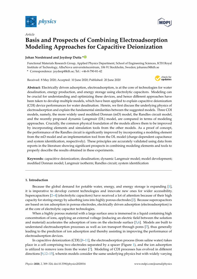
Article
Basis and Prospects of Combining ElectroadsorptionModeling Approaches for Capacitive Deionization
Johan Nordstrand and Joydeep Dutta *
Functional Materials Research Group, Applied Physics Department, School of Engineering Sciences, KTH RoyalInstitute of Technology, AlbaNova universitetscentrum, 106 91 Stockholm, Sweden; [email protected]* Correspondence: [email protected]; Tel.: +46-8-790-81-42
Received: 8 May 2020; Accepted: 10 June 2020; Published: 20 June 2020�����������������
Abstract: Electrically driven adsorption, electroadsorption, is at the core of technologies for waterdesalination, energy production, and energy storage using electrolytic capacitors. Modeling canbe crucial for understanding and optimizing these devices, and hence different approaches havebeen taken to develop multiple models, which have been applied to explain capacitive deionization(CDI) device performances for water desalination. Herein, we first discuss the underlying physics ofelectroadsorption and explain the fundamental similarities between the suggested models. Three CDImodels, namely, the more widely used modified Donnan (mD) model, the Randles circuit model,and the recently proposed dynamic Langmuir (DL) model, are compared in terms of modelingapproaches. Crucially, the common physical foundation of the models allows them to be improvedby incorporating elements and simulation tools from the other models. As a proof of concept,the performance of the Randles circuit is significantly improved by incorporating a modeling elementfrom the mD model and an implementation tool from the DL model (charge-dependent capacitanceand system identification, respectively). These principles are accurately validated using data fromreports in the literature showing significant prospects in combining modeling elements and tools toproperly describe the results obtained in these experiments.
Keywords: capacitive deionization; desalination; dynamic Langmuir model; model development;modified Donnan model; Langmuir isotherm; Randles circuit; system identification
1. Introduction
Because the global demand for potable water, energy, and energy storage is expanding [1],it is imperative to develop current technologies and innovate new ones for wider accessibility.Supercapacitors [2–4] (electrolytic capacitors) have received a lot of attention because of their highcapacity for storing energy by adsorbing ions into highly porous electrodes [2]. Because supercapacitorsare based on ion adsorption in porous electrodes, electrically driven adsorption (electroadsorption) isat the core of electrolytic capacitor technologies.
When a highly porous material with a large surface area is immersed in a liquid containing highconcentration of ions, applying an external voltage (inducing an electric field between the solutionand material) accelerates the adsorption of ions on the electrode surface [5,6]. Models are built tounderstand electroadsorption processes as well as ion transport through pores [7], thus generallyleading to the prediction of ion adsorption and thereby assisting in improving the performance ofelectroadsorption devices.
In capacitive deionization (CDI) [8–11], the electroadsorption process (from saline water) takesplace in a cell comprising two electrodes separated by a spacer (Figure 1), and the ion adsorptionis utilized to remove ions from the water [7]. Modeling of CDI processes has evolved in differentdirections [9,12–15], wherein models consider the same underlying physics but with widely varying
Physics 2020, 2, 309–324; doi:10.3390/physics2020016 www.mdpi.com/journal/physics

Physics 2020, 2 310
approaches for its implementation. Limited crossover in formulation and implementation limits theirpotential usefulness, meaning they could be profitably and integrally developed by incorporatingideas and tools from the other modeling approaches.
Physics 2020, 2 FOR PEER REVIEW 2
approaches for its implementation. Limited crossover in formulation and implementation limits their
potential usefulness, meaning they could be profitably and integrally developed by incorporating
ideas and tools from the other modeling approaches.
Figure 1. A schematic representation of capacitive deionization (CDI) cell typically comprising two
porous electrodes separated by a spacer. When a potential is applied across the electrodes, the ions in
the water flowing through such device adsorb on the electrodes.
Herein, we discuss the underlying model-independent physics governing electroadsorption.
Primarily, this is used as a starting point for comparing the approaches and tools used in three
different CDI models: the modified Donnan (mD) model [7–9,16–18], the Randles circuit [12], and the
dynamic Langmuir (DL) model [13,19,20]. Crucially, we add value by discussing how tools used in
the respective models could be implemented to enhance the other models. As a proof of concept, a
system identification method from the DL model is implemented to significantly improve simulation
performance of the Randles circuit.
2. Materials and Methods
2.1. Theory
This section discusses the fundamental physics involved in electroadsorption processes. Mainly,
the principles behind the Randles circuit, mD, and DL modeling approaches are discussed and
compared. Finally, we discuss the differences in how these models are implemented, including how
fitting parameters are extracted.
2.1.1. The Physics Behind the Models
In CDI devices, highly porous electrodes with high surface area are used for maximum
adsorption sites for the ions. Let us consider a piece of porous material thoroughly soaked with
saltwater [21–23] (Figure 2). Now, activated carbon cloth (ACC) is a popular choice of electrode
material [23–25]. To clarify the porous structure, note that ACC, for instance, has been shown to
comprise ~70% pores [7], which can be classified according to size (diameter 𝑑) as micropores (𝑑 < 2
nm), mesopores (2 nm < 𝑑 < 50 nm), or macropores (𝑑 > 50 nm) [26]. Thus, the ACC cloth can be seen
as an amalgamation of fibers with tiny holes (micro- and mesopores) and open spaces between them
(macropores).
Figure 1. A schematic representation of capacitive deionization (CDI) cell typically comprising twoporous electrodes separated by a spacer. When a potential is applied across the electrodes, the ions inthe water flowing through such device adsorb on the electrodes.
Herein, we discuss the underlying model-independent physics governing electroadsorption.Primarily, this is used as a starting point for comparing the approaches and tools used in threedifferent CDI models: the modified Donnan (mD) model [7–9,16–18], the Randles circuit [12], and thedynamic Langmuir (DL) model [13,19,20]. Crucially, we add value by discussing how tools used inthe respective models could be implemented to enhance the other models. As a proof of concept,a system identification method from the DL model is implemented to significantly improve simulationperformance of the Randles circuit.
2. Materials and Methods
2.1. Theory
This section discusses the fundamental physics involved in electroadsorption processes.Mainly, the principles behind the Randles circuit, mD, and DL modeling approaches are discussed andcompared. Finally, we discuss the differences in how these models are implemented, including howfitting parameters are extracted.
2.1.1. The Physics Behind the Models
In CDI devices, highly porous electrodes with high surface area are used for maximum adsorptionsites for the ions. Let us consider a piece of porous material thoroughly soaked with saltwater [21–23](Figure 2). Now, activated carbon cloth (ACC) is a popular choice of electrode material [23–25].To clarify the porous structure, note that ACC, for instance, has been shown to comprise ~70% pores [7],which can be classified according to size (diameter d) as micropores (d < 2 nm), mesopores (2 nm < d <
50 nm), or macropores (d > 50 nm) [26]. Thus, the ACC cloth can be seen as an amalgamation of fiberswith tiny holes (micro- and mesopores) and open spaces between them (macropores).

Physics 2020, 2 311
Physics 2020, 2 FOR PEER REVIEW 3
Figure 2. A schematic illustration showing a zoomed-in view (two carbon fibers from the knitted
carbon cloth) of an electrode. The macropores in the electrode are the primary pathways for the water
flow. Most of the ion adsorption occurs in the micropores because they carry most of the electrode
area.
Water naturally passes through the open space, making the macropores the primary pathways
for water flow, while the micropores intuitively hold most of the surface area because of their high
area-to-volume ratio, rendering them suitable as the primary location for salt adsorption [7]. Most of
the adsorption is thus thought to occur in pores smaller than 2 nm, and around half of the micropore
volume constitutes of pores smaller than 1 nm (see Figure S3 in Ref. [27]). Incidentally, the micropores
and hydrated sizes of atoms are quite comparable (hydrated diameter of sodium is 0.72 nm) [28],
suggesting that few atoms can fit neck-to-neck across the diameter of a single micropore (for a more
thorough discussion regarding ion and pore sizes, see [2]).
When a potential difference is abruptly induced between the pore material and the solution, ions
will rapidly begin to electroadsorb on the electrodes by migrating to the micropores because of the
induced electric field, cations adsorbing on the anodes, and vice versa. The exact performance varies
between electrodes; however, such porous electrodes hold around 𝑚𝑎𝑑𝑠 = 10 mg salt per gram of
electrode [25,29–31], while the effective specific surface area is around 𝐴 = 1000 m2/g [22,32,33]. To
put this in perspective, let us consider the fraction of the projected area of adsorbed ions to the total
electrode area, denoted by η (Equation (1)). In this equation, 𝑀𝑁𝑎𝐶𝑙 is the NaCl molar weight, 𝑁𝐴 is
the Avogadro number, and 𝑟𝑥 is the hydrated radius of species 𝑥. To clarify, π(𝑟𝑁𝑎+2 + 𝑟𝐶𝑙−
2 ) is thus
the projected area per atom, scaled to mole through 𝑁𝐴, scaled to weight through 𝑀𝑁𝑎𝐶𝑙. This area
per weight is compared to the mass adsorption, scaled by the electrode weight per area A. Using
hydrated radii from [28], the hypothetical fractional coverage if all adsorbed ions are stacked neck-
to-neck is thus computed to 8%.
η = 𝑚𝑎𝑑𝑠
𝑁𝐴π(𝑟𝑁𝑎+2 + 𝑟𝐶𝑙−
2 )
𝑀𝑁𝑎𝐶𝑙𝐴= 8 % (1)
Ideally, electroadsorption is the only process occurring in the pores. However, Faradaic
reactions (carbon oxidation [34]) can lead to a transfer of charge from the electrode through the
solution [16]. In addition, it has been generally found that micropores can carry a net charge, which
is balanced by ions from the solution even before an external potential is applied, altering the point
of zero charge (PZC) [8,35]. Some of these balancing ions present in the micropores (well-known
Langmuir adsorption) are expelled upon the application of electric field [7]. This means not all
charges induced on the electrodes will have corresponding counterions adsorbed from the solution
[33,36–38].
2.1.2. From Physics to Model
It has been said that “all models are wrong but some are useful” [39]. Generally, a model is a
simplification representing some aspects of reality, and the value of a model is logically judged not
purely by how closely it matches reality but rather how well it completes the task for which it was
Figure 2. A schematic illustration showing a zoomed-in view (two carbon fibers from the knittedcarbon cloth) of an electrode. The macropores in the electrode are the primary pathways for the waterflow. Most of the ion adsorption occurs in the micropores because they carry most of the electrode area.
Water naturally passes through the open space, making the macropores the primary pathwaysfor water flow, while the micropores intuitively hold most of the surface area because of their higharea-to-volume ratio, rendering them suitable as the primary location for salt adsorption [7]. Most ofthe adsorption is thus thought to occur in pores smaller than 2 nm, and around half of the microporevolume constitutes of pores smaller than 1 nm (see Figure S3 in Ref. [27]). Incidentally, the microporesand hydrated sizes of atoms are quite comparable (hydrated diameter of sodium is 0.72 nm) [28],suggesting that few atoms can fit neck-to-neck across the diameter of a single micropore (for a morethorough discussion regarding ion and pore sizes, see [2]).
When a potential difference is abruptly induced between the pore material and the solution,ions will rapidly begin to electroadsorb on the electrodes by migrating to the micropores because ofthe induced electric field, cations adsorbing on the anodes, and vice versa. The exact performancevaries between electrodes; however, such porous electrodes hold around mads = 10 mg salt per gramof electrode [25,29–31], while the effective specific surface area is around A = 1000 m2/g [22,32,33].To put this in perspective, let us consider the fraction of the projected area of adsorbed ions to the totalelectrode area, denoted by η (Equation (1)). In this equation, MNaCl is the NaCl molar weight, NA isthe Avogadro number, and rx is the hydrated radius of species x. To clarify, π
(r2
Na+ + r2Cl−
)is thus the
projected area per atom, scaled to mole through NA, scaled to weight through MNaCl. This area perweight is compared to the mass adsorption, scaled by the electrode weight per area A. Using hydratedradii from [28], the hypothetical fractional coverage if all adsorbed ions are stacked neck-to-neck isthus computed to 8%.
η = madsNAπ(r2
Na+ + r2Cl−
)MNaClA
= 8% (1)
Ideally, electroadsorption is the only process occurring in the pores. However, Faradaic reactions(carbon oxidation [34]) can lead to a transfer of charge from the electrode through the solution [16].In addition, it has been generally found that micropores can carry a net charge, which is balancedby ions from the solution even before an external potential is applied, altering the point of zerocharge (PZC) [8,35]. Some of these balancing ions present in the micropores (well-known Langmuiradsorption) are expelled upon the application of electric field [7]. This means not all charges inducedon the electrodes will have corresponding counterions adsorbed from the solution [33,36–38].
2.1.2. From Physics to Model
It has been said that “all models are wrong but some are useful” [39]. Generally, a model is asimplification representing some aspects of reality, and the value of a model is logically judged notpurely by how closely it matches reality but rather how well it completes the task for which it wasconstructed. Thus, models can be constructed from different starting points in terms of modeling tools.

Physics 2020, 2 312
Several models have been constructed considering an electric circuit with a capacitiveelement [40–42] as the electrode together with the ions constitutes an electrolytic (double layer)capacitor. Thus, a Randles circuit [12] accounts for storage through a capacitive element C, the timescales of adsorption through a resistive element R1, and charge leakages through a second resistiveelement R2 (Figure 3). This basic principle can also be specified further through a transmission linemodel where more elements are added [43–45]. Interestingly, such a model might be able to calculatecharge storage over time [12], even though the physics at a pore-scale level is ignored and the impactof changing parameters, such as the ion concentration, cannot be predicted.
Physics 2020, 2 FOR PEER REVIEW 4
constructed. Thus, models can be constructed from different starting points in terms of modeling
tools.
Several models have been constructed considering an electric circuit with a capacitive element
[40–42] as the electrode together with the ions constitutes an electrolytic (double layer) capacitor.
Thus, a Randles circuit [12] accounts for storage through a capacitive element 𝐶, the time scales of
adsorption through a resistive element 𝑅1, and charge leakages through a second resistive element
𝑅2 (Figure 3). This basic principle can also be specified further through a transmission line model
where more elements are added [43–45]. Interestingly, such a model might be able to calculate charge
storage over time [12], even though the physics at a pore-scale level is ignored and the impact of
changing parameters, such as the ion concentration, cannot be predicted.
(a)
(b)
Figure 3. A simple circuit for describing the dynamics of a charging electrode. (a) During charging,
the capacitive element 𝐶 relates to how much charge can be stored, the series resistance 𝑅1 governs
the rate of the current, and the resistance 𝑅2 determines the charge leakage. 𝑉𝑒𝑥𝑡 is the applied
voltage. (b) When the voltage is removed, the capacitive element acts as a battery, and the stored
charge is released. The charge can be released either through the external circuit (𝑅1) or as leakage
current through the resistive element (𝑅2).
Models starting from a pore-scale level often consider an electric double layer (EDL) being
formed near the electrode surface [46]. The EDL theory has developed over time. The early Helmholtz
model viewed ions as being able to form a monolayer on the electrode surface [47]. Gouy and
Chapman argued that diffusive forces should create a concentration gradient out from the electrode
surface [48], and Stern introduced the notion of a thicker layer, the Stern layer, close to the surface
followed by a less concentrated region, the diffuse layer [47]. Finally, in the modified Donnan model
[7–9,16–18], it is recognized that the micropores are so small that the diffuse layers overlap, meaning
it is enough to only consider a Stern layer [49] (Figure 4).
Figure 3. A simple circuit for describing the dynamics of a charging electrode. (a) During charging,the capacitive element C relates to how much charge can be stored, the series resistance R1 governs therate of the current, and the resistance R2 determines the charge leakage. Vext is the applied voltage.(b) When the voltage is removed, the capacitive element acts as a battery, and the stored charge isreleased. The charge can be released either through the external circuit (R1) or as leakage currentthrough the resistive element (R2).
Models starting from a pore-scale level often consider an electric double layer (EDL) being formednear the electrode surface [46]. The EDL theory has developed over time. The early Helmholtz modelviewed ions as being able to form a monolayer on the electrode surface [47]. Gouy and Chapmanargued that diffusive forces should create a concentration gradient out from the electrode surface [48],and Stern introduced the notion of a thicker layer, the Stern layer, close to the surface followed by aless concentrated region, the diffuse layer [47]. Finally, in the modified Donnan model [7–9,16–18], it isrecognized that the micropores are so small that the diffuse layers overlap, meaning it is enough toonly consider a Stern layer [49] (Figure 4).

Physics 2020, 2 313
Physics 2020, 2 FOR PEER REVIEW 5
Figure 4. A detailed view of the interface between a micropore and the surrounding macropore. In
the Donnan model, the water flows through the macropores, which are net uncharged. The ion
adsorption occurs mainly in the micropores (the cavity in the image) and is enhanced when voltage
is applied. Mathematically, the ions are considered to form a small Stern layer against the pore walls
(circled green in the image).
Mathematically (see full model including a derivation in [7]), it is thus argued that the difference
in potential between the pore matrix, ϕ𝑒, and the solution in the macropores, ϕ, can be split into two
components (Equation (2)). The potential drop from the pore matrix to the micropore center, Δϕ𝑚,
determines the charge in the micropore based on the Stern layer capacitance. In addition, the potential
drop from the micropore center to the macropore, Δϕ𝐷, determines the charge and salt concentration
in the micropore relative to the macropore. Finally, the driving force enhancing adsorption is the
potential distribution across macropores from different regions in the cell.
ϕ𝑒 − ϕ = Δϕ𝑚 + Δϕ𝐷 (2)
In CDI devices, the mD theory can describe the performance under various structural conditions,
such as varying electrode sizes [50], spacer thicknesses [50], and electrolyte ion compositions [51,52]
as well as operational conditions, such as flow rates [53] and ion concentrations [49]. It has also been
further developed to describe not only the outlet ion concentrations but also the concentration
variation within the CDI cell in 1D [18] and 2D [7,27] models.
Rather than considering the circuit or EDL approaches, some other models have approached
electroadsorption of ions from an adsorption kinetics point of view. The voltage is the driving attractive
force and the rate at which ions can reach the electrode surface depending on the ion concentration in
the water. Moreover, the more ions already adsorbed in the tiny micropores, the more difficult it is for
new ions to reach the surface in such a way that they can get adsorbed (Figure 5).
Figure 5. The same situation as in Figure 4 but from a Langmuir adsorption perspective. Depending
on the material, applied voltage, etc., there are only a fixed number of sites onto which the ions can
be adsorbed.
Figure 4. A detailed view of the interface between a micropore and the surrounding macropore. In theDonnan model, the water flows through the macropores, which are net uncharged. The ion adsorptionoccurs mainly in the micropores (the cavity in the image) and is enhanced when voltage is applied.Mathematically, the ions are considered to form a small Stern layer against the pore walls (circled green inthe image).
Mathematically (see full model including a derivation in [7]), it is thus argued that the differencein potential between the pore matrix, φe, and the solution in the macropores, φ, can be split into twocomponents (Equation (2)). The potential drop from the pore matrix to the micropore center, ∆φm,determines the charge in the micropore based on the Stern layer capacitance. In addition, the potentialdrop from the micropore center to the macropore, ∆φD, determines the charge and salt concentrationin the micropore relative to the macropore. Finally, the driving force enhancing adsorption is thepotential distribution across macropores from different regions in the cell.
φe −φ = ∆φm + ∆φD (2)
In CDI devices, the mD theory can describe the performance under various structural conditions,such as varying electrode sizes [50], spacer thicknesses [50], and electrolyte ion compositions [51,52] aswell as operational conditions, such as flow rates [53] and ion concentrations [49]. It has also beenfurther developed to describe not only the outlet ion concentrations but also the concentration variationwithin the CDI cell in 1D [18] and 2D [7,27] models.
Rather than considering the circuit or EDL approaches, some other models have approachedelectroadsorption of ions from an adsorption kinetics point of view. The voltage is the driving attractiveforce and the rate at which ions can reach the electrode surface depending on the ion concentration inthe water. Moreover, the more ions already adsorbed in the tiny micropores, the more difficult it is fornew ions to reach the surface in such a way that they can get adsorbed (Figure 5).
Physics 2020, 2 FOR PEER REVIEW 5
Figure 4. A detailed view of the interface between a micropore and the surrounding macropore. In
the Donnan model, the water flows through the macropores, which are net uncharged. The ion
adsorption occurs mainly in the micropores (the cavity in the image) and is enhanced when voltage
is applied. Mathematically, the ions are considered to form a small Stern layer against the pore walls
(circled green in the image).
Mathematically (see full model including a derivation in [7]), it is thus argued that the difference
in potential between the pore matrix, ϕ𝑒, and the solution in the macropores, ϕ, can be split into two
components (Equation (2)). The potential drop from the pore matrix to the micropore center, Δϕ𝑚,
determines the charge in the micropore based on the Stern layer capacitance. In addition, the potential
drop from the micropore center to the macropore, Δϕ𝐷, determines the charge and salt concentration
in the micropore relative to the macropore. Finally, the driving force enhancing adsorption is the
potential distribution across macropores from different regions in the cell.
ϕ𝑒 − ϕ = Δϕ𝑚 + Δϕ𝐷 (2)
In CDI devices, the mD theory can describe the performance under various structural conditions,
such as varying electrode sizes [50], spacer thicknesses [50], and electrolyte ion compositions [51,52]
as well as operational conditions, such as flow rates [53] and ion concentrations [49]. It has also been
further developed to describe not only the outlet ion concentrations but also the concentration
variation within the CDI cell in 1D [18] and 2D [7,27] models.
Rather than considering the circuit or EDL approaches, some other models have approached
electroadsorption of ions from an adsorption kinetics point of view. The voltage is the driving attractive
force and the rate at which ions can reach the electrode surface depending on the ion concentration in
the water. Moreover, the more ions already adsorbed in the tiny micropores, the more difficult it is for
new ions to reach the surface in such a way that they can get adsorbed (Figure 5).
Figure 5. The same situation as in Figure 4 but from a Langmuir adsorption perspective. Depending
on the material, applied voltage, etc., there are only a fixed number of sites onto which the ions can
be adsorbed.
Figure 5. The same situation as in Figure 4 but from a Langmuir adsorption perspective. Depending on thematerial, applied voltage, etc., there are only a fixed number of sites onto which the ions can be adsorbed.

Physics 2020, 2 314
The Langmuir isotherm was created to describe monolayer adsorption of gases on a surface [54],which has traditionally been adopted for liquids as well [55]. Equation (3) shows the rate at which thefractional surface coverage θ increases with time. Here, c is the ion concentration in a liquid, and kads andkdes are constants. Equation (4) shows the Langmuir isotherm, that is, the equilibrium fractional surfacecoverage θe, depending on the constant KL and the equilibrium concentration ce. Crucially, the Langmuirisotherm thus models the variation in adsorption based on the ion concentration.
dθdt
= kadsc(1− θ)–kdesθ (3)
θe =KLce
1 + KLce(4)
Because of the above similarities between traditional Langmuir adsorption and electroadsorption,it is interesting to note that several studies have successfully implemented the Langmuir isotherm toaccurately describe variations in electroadsorption based on the ion concentration in the liquid [56–65].Note also that the Langmuir model (monolayer adsorption) was shown to be more accurate than theFreundlich model (multilayer adsorption) [57,58], which might be related to the limited size of themicropores in which the ions adsorb.
The Langmuir isotherm has mainly been implemented to describe the equilibrium state.However, there are fundamental similarities between the Langmuir model and Lagergrenpseudo-first-order kinetics [65], as the Lagergren first-order model has been implemented to describereaction kinetics in terms of how the adsorption varies with time in CDI [57,63,66–68]. Equation (5)(or, equivalently, Equation (6)) demonstrates how the adsorbed quantity Nt (unit mg/g) varies withtime, depending on the rate constant k1 and the equilibrium adsorption Ne [65]. Notably, this modelhas been very accurate in modeling electroadsorption, with R2 regression values as high as 0.99 [67].
dNt
dt= k1(Ne–Nt) (5)
ln(Ne−Nt) = ln(Ne)–k1t (6)
However, while these formulations have been able to describe some aspects of electroadsorption,including concentration dependence and performance over time, several key elements are not included,such as co-ion expulsion.
2.1.3. Dynamic Langmuir Model
While traditional adsorption and electroadsorption processes are quite similar, there are severalkey features of an electroadsorption system that are not included in the classic Langmuir model.To address this, note that the fundamental mechanism of electroadsorption consists of the chargedspecies, σ (unit mM), being adsorbed on the electrode surface due to the application of an electricalpotential (Equation (7)) [13]. At equilibrium, the time derivative is zero and σe = zce in the solution(z is the ion valency, subscript “e” denotes equilibrium quantity), and Equation (7) thus becomesEquation (8) for the specific charge storage Σ. Here, S denotes the effective number of surface sites, ρ isthe electrode mass per cell volume, and A, B, A’, B’ are constants.
dσadsdt
= kadsσ(S− σads)–kdesσads (7)
Σ[C/g] =F[sA/mol]ρ[g/L]
σe[mol/L] =Fρ
Ace
1 + Bce=
A′ce
1 + Bce(8)
Not all charge storage contributes to net ion adsorption (there is unideal charge efficiency).Thus, it has been shown experimentally that a pure Langmuir isotherm cannot accurately describevariation in adsorption over a wide concentration range [9]. One major effect that contributes to this

Physics 2020, 2 315
discrepancy is co-ion expulsion. If some of the capacity for storing charged species is used for pushingaway co-ions rather than adsorbing counterions, the net ion adsorption is reduced.
Co-ions can be present close to the electrode to neutralize native charge, that is, charged groupsthat are situated on the electrode surface. In addition, the ions can be passively present close to theelectrode surface due to the ion concentration in the water. With β0 and β1 being constants, the effectivenumber of sites is thus reduced proportionately to the number of ions that are pushed out, including aconstant factor (β0) and one that is linear with the concentration (β1c0), resulting in Equation (9) forthe ion adsorption over time. At equilibrium, this can be simplified to Equation (10) for the specific ionadsorption. Here, Mv is the salt molar weight, and A, B, D, A′′ , D′′ are constants.
dcadsdt
= kadsc(S−β0 −β1c0–cadsz)–kdescads (9)
Γ[mg/g] =Mv[mg/mol]
ρ[g/L]ce[mol/L] =
Mv
ρ
Ac0 −Dc20
1 + Bc0=
A′′ c0 −D′′ c20
1 + Bc0(10)
In classical Langmuir adsorption, the process is driven by an affinity for the molecules to reachthe adsorption sites. Because these sites ultimately determine the total adsorption, they will changedepending on experimental conditions and specifically the material used for adsorption of the ions.In the DL model, the sites S are expected to change depending on the electrode material, electrodesurface modifications, cell structure, etc. Because the magnitude of the applied voltage determinesthe total possible charge storage, the sites S will ultimately be dependent on the applied voltage,that is, S denotes “voltage-induced” sites. Specifically, because the charge on a capacitor increasesproportionately with the applied voltage, so too does S. In Equations (8) and (10), this corresponds tothe constant A (and therefore also A′ and A′′ ) being proportional to the voltage.
These fundamental equations have been shown to accurately model the charge storage and ionadsorption over varying concentrations and voltages. The full DL model, as derived elsewhere [13,19,20],has also been able to predict performance for multi-ion systems [20] and adsorption over time [19].
2.1.4. Ion Transport
A desalination device based on the porous electrodes discussed in previous sections typicallycomprises two electrodes separated by a spacer. Depending on the device, the water can flow eitherbetween the electrodes or directly through them during operation. Either way, the flow rate is importantas it influences how quickly cleaned water is collected at the output and how quickly new ions arebrought to the electrodes. Thus, the desalination efficiency of the devices is affected by not only ionadsorption but also the flow rate.
Principally, the change in concentration at a given time and location in the cell depends on theadsorption at that location and the net influx of ions. Therefore, it can be described by the masstransport equation, where ctot is the total ion content (sum of adsorbed and free ions) and j is the ionflux (Equation (11)) [7]. In some studies, this has been implemented directly to create partial differentialequations (PDEs) describing the system [7].
However, such a formulation can be computationally heavy and difficult to compute.Note, therefore, that the equivalent principle for a region of any size V that is “well-stirred” (the ionconcentration is uniform) is that the concentration changes at a rate determined by the adsorption rateand the ion influx. The ion influx, in turn, is derived from the flow Q and the influent concentrationcin (Equations (12) and (13)) [27]. Thus, the mass transport calculation can be simplified by treatingthe entire cell as one volume (influent concentration cin = c0, the cell inlet ion concentration) [19].Alternatively, the cell volume could be divided into some number of subcells i = [1, . . . , n] along theflow axis, where the influent concentration to subcell i is ci−1, and the concentration flowing out of thecell is cn [27].
dctot
dt+∇ · j = 0 (11)

Physics 2020, 2 316
Vc(t + dt) = Vc(t)–V(cads(t + dt) − cads(t)) + (Q(cin − c)dt) (12)
dcdt
= −dcads
dt+
QV(cin − c) (13)
2.1.5. Implementing a Model
All the presented models contain fitting parameters that can only be deduced by comparing themodel formulation to experimental data. Doing so will reveal whether the model can describe thedata, that is, if there is any set of parameter values for which the model matches the experimental data.Ideally, the model should then be able to predict the performance under new conditions using thealready extracted parameter values.
Traditionally, experimental measurements are done to extract specific parameters. In the circuitmodel shown in Figure 3, for instance, the current and voltage over time are determined. When thevoltage is just applied, the voltage across the capacitor is zero, so the entire external voltage workstowards pushing current through R1, meaning R1 = Vext/Iinitial. Here, Vext is the externally appliedvoltage to the cell (see Figure 3), and Iinitial is the current through R1 shortly after the voltageis applied. Similarly, no current goes through the capacitor at equilibrium, so from Ohms law,Vext = Ie(R1 + R2)→ R2 = (Vext/Ie)–R1. Normally in a capacitor, C = Vext/q, where q is the totalcharge built up in the capacitor (integral of current). Because of charge leakages, the voltage here shouldbe the voltage across the capacitor. At equilibrium, that voltage is VC = R2Iext. However, the charge qcannot be deduced without knowing how much of the passed current has leaked instead of passingthrough the capacitor. Because generally R2 � R1 (there is a high resistance against charge leakages),an approximate value of q can be recorded by measuring how much charge is released (externallythrough R1) upon removal of the electrical potential.
Another example of fitting can be seen in a full 2D modeling study of a flow-between CDI cellusing the mD model [7]. The total passed current and the total salt adsorption at equilibrium weremeasured. These were used to extract parameters for the capacitance of the device and the baseline(nonelectrostatic) force attracting the ions to the micropores. Then, different values of the fractionalvolume of micropores, pm, in the electrode material were manually inserted until the simulationmatched the experimental data for the effluent ion concentration over time.
Based on the above examples, at least three issues can arise in the classic view on parameterfitting. Firstly, the extracted values may not be accurate because of the utilization of a limited set ofdata. Secondly, it may not be possible to make a measurement such that the parameter value can beautomatically calculated because there is a complex relationship between parameter values and whatcan be measured. Thirdly, as will be shown in the result section, extracting values for each parameterseparately can result in small errors that accumulate over several cycles of operation.
A more effective way of extracting parameter values would be to implement a system identificationmethod. If a problem can be formulated in a system identification form, programs such as MATLAB canbe used because they contain toolboxes to automatically find parameter values for linear and nonlinearsystems [68]. These toolboxes match the experimental data over time to the model formulation toautomatically extract the best parameter values. This method brings forward several advantages.Firstly, all data, from the beginning when the voltage is applied until saturation is reached, can be usedfor the fitting, which means that mode reliable values can be found. Secondly, the parameter valuesare automatically extracted. Thirdly, all parameters are extracted at the same time and multiple cyclescan be considered, meaning that the stability of the simulated model can be confirmed over multiplecycles of operation.
In setting up a model using the mentioned toolboxes [68], a set of internal states x are defined thatcan correspond to different properties (such as adsorption and charge storage) and/or different points
in space. It is required that the time derivative.x of each state can be expressed in terms of the current
state x and the input u (e.g., voltage, influent ion concentration) at a given time. In addition, it shouldbe possible to express the measured output data y (e.g., the ion concentration of the effluent water)

Physics 2020, 2 317
in terms of the current state x and the input u. Thus, the simulated values of y will be related to theexperimental data to find the best parameter values.
As an example, the internal states x for the circuit model would be the charge passing through R1,R2, and C, while the output state would be the current through R1. Thus, the parameter values aredirectly and automatically extracted based on the voltage and current over time. Because these toolboxesrequire computation at a discrete number of points, they are not directly compatible with some of themore detailed models available, including the 2D PDE-based mD model [7]. However, the toolboxesare not entirely new in describing CDI processes as they have previously been implemented with theDL model [19].
2.2. Data for Model Validation
To validate claims from the theory section and to illustrate some aspects of the modeling andimplementation of models, experimental data were extracted from published reports in the literature.The data extraction was carried out using the WebPlotDigitizer software [69].
For the Randles circuit model, the report was chosen based on displaying passed charge over timefor an operation where the voltage was applied for a long time so the leakages were accumulated so asto be clearly distinguished in a graph.
3. Results
3.1. DL Model and the Randles Circuit
Here, we illustrate some differences between classical parameter extraction and the systemidentification used in the DL model in the context of CDI modeling. Because the Randles circuit modelcontains few components, it is chosen to transparently begin to highlight these differences.
Bouhadana et al. studied the charge leakages in CDI and measured how much charge wassupplied to their CDI cell over time [70]. Thus, in Figure 6, the charge can be seen as increasing whenthe voltage is applied (adsorption phase “Ads.”), decreasing when the voltage is removed (desorptionphase “Des.”), and the leakages constitute the differences between the supplied and released chargedions over a full cycle of applying and removing the voltage.
Physics 2020, 2 FOR PEER REVIEW 9
As an example, the internal states �̅� for the circuit model would be the charge passing through
𝑅1, 𝑅2, and 𝐶, while the output state would be the current through 𝑅1. Thus, the parameter values
are directly and automatically extracted based on the voltage and current over time. Because these
toolboxes require computation at a discrete number of points, they are not directly compatible with
some of the more detailed models available, including the 2D PDE-based mD model [7]. However,
the toolboxes are not entirely new in describing CDI processes as they have previously been
implemented with the DL model [19].
2.2. Data for Model Validation
To validate claims from the theory section and to illustrate some aspects of the modeling and
implementation of models, experimental data were extracted from published reports in the literature.
The data extraction was carried out using the WebPlotDigitizer software [69].
For the Randles circuit model, the report was chosen based on displaying passed charge over
time for an operation where the voltage was applied for a long time so the leakages were accumulated
so as to be clearly distinguished in a graph.
3. Results
3.1. DL Model and the Randles Circuit
Here, we illustrate some differences between classical parameter extraction and the system
identification used in the DL model in the context of CDI modeling. Because the Randles circuit model
contains few components, it is chosen to transparently begin to highlight these differences.
Bouhadana et al. studied the charge leakages in CDI and measured how much charge was
supplied to their CDI cell over time [70]. Thus, in Figure 6, the charge can be seen as increasing when
the voltage is applied (adsorption phase “Ads.”), decreasing when the voltage is removed
(desorption phase “Des.”), and the leakages constitute the differences between the supplied and
released charged ions over a full cycle of applying and removing the voltage.
(a) (b)
Figure 6. The total accumulated current passed through a CDI device over multiple cycles of
adsorption at 0.9 V and desorption with no applied voltage. Data from [70]. Note that the difference
between the adsorbed and released charge constitutes the leakage. (a) The circuit model was
implemented using classic parameter extraction as derived in the theory section. (b) The circuit model
was implemented using a nlgreyest system identification method in MATLAB for parameter
extraction (program code in Supplementary S1).
Using the classic parameter extraction method as described in the theory section, the Randles
circuit model can be implemented for this data set. Figure 6a indicates that there is quite a reasonable
fit between the model and experiment for the extracted values. However, the errors that are present
tend to accumulate over multiple cycles of operation, meaning the data for the experiment and results
from the model for charge accumulation diverge over time.
If the same underlying model is implemented with the nlgreyest system identification method
in MATLAB, a perfect fit between the model and experiment is obtained. Crucially, this fit endures
Figure 6. The total accumulated current passed through a CDI device over multiple cycles of adsorptionat 0.9 V and desorption with no applied voltage. Data from [70]. Note that the difference between theadsorbed and released charge constitutes the leakage. (a) The circuit model was implemented usingclassic parameter extraction as derived in the theory section. (b) The circuit model was implementedusing a nlgreyest system identification method in MATLAB for parameter extraction (program codein Supplementary S1).
Using the classic parameter extraction method as described in the theory section, the Randlescircuit model can be implemented for this data set. Figure 6a indicates that there is quite a reasonablefit between the model and experiment for the extracted values. However, the errors that are present

Physics 2020, 2 318
tend to accumulate over multiple cycles of operation, meaning the data for the experiment and resultsfrom the model for charge accumulation diverge over time.
If the same underlying model is implemented with the nlgreyest system identification methodin MATLAB, a perfect fit between the model and experiment is obtained. Crucially, this fit enduresover many cycles of operation (Figure 6b). The code for automatically implementing this method hasbeen supplied in the Supplementary Materials.
An interesting point will emerge when looking specifically at how random experimental errortransfers to the model fit. Figure 7 shows an experiment for the same device as in Figure 6 but with anapplied voltage of 1.1 V. Using the classic parameter extraction method, there is a significantly worsemodel fit even in the first cycle of operation compared to Figure 6a. Crucially, this quickly accumulatesbetween cycles and automatically makes the transferred charge described by the model diverge fromwhat is obtained from experimental data.
Physics 2020, 2 FOR PEER REVIEW 10
over many cycles of operation (Figure 6b). The code for automatically implementing this method has
been supplied in the Supplementary Materials.
An interesting point will emerge when looking specifically at how random experimental error
transfers to the model fit. Figure 7 shows an experiment for the same device as in Figure 6 but with
an applied voltage of 1.1 V. Using the classic parameter extraction method, there is a significantly
worse model fit even in the first cycle of operation compared to Figure 6a. Crucially, this quickly
accumulates between cycles and automatically makes the transferred charge described by the model
diverge from what is obtained from experimental data.
(a) (b)
Figure 7. The total accumulated current passed through a CDI device over multiple cycles of
adsorption at 1.1 V and desorption with no applied voltage. Data from [70]. Note that the difference
between the adsorbed and released charge constitutes the leakage. (a) The circuit model was
implemented using classic parameter extraction as derived in the theory section. (b) The circuit model
was implemented using a nlgreyest system identification method in MATLAB for parameter
extraction.
When the system identification method is implemented, there is still an error in the first cycle of
operation, suggesting that the model formulation could not accurately describe what happened at
the beginning of the operation. However, the cumulative charge as described by the model converges
with the experimental data over time, making the errors smaller. This suggests that the system
identification method can reach accurate results even if there are random variations at the beginning
of the experiment data.
This finding is especially relevant to CDI because it typically takes time before a CDI device
reaches a stable operation, meaning the quality of the experimental data can be poor for the first few
adsorption/desorption cycles before stability is reached. With a system identification method, the
sensitivity to such variations is low.
The crucial point to note is that the difference between the fitting methods shown above means
the fitting method fundamentally impacts the model performance even when the underlying model
structure is the same. Ultimately, this means it could be valuable to investigate how to make models
compatible with advanced parameter extraction methods.
3.2. mD Model and the Randles Circuit
Now, there are also prospects from incorporating elements from the mD model into the Randles
circuit. As an example of this, it can be noted that the charge accumulation on electrolytic capacitors
is not directly proportional to the applied voltage. This means that the capacitance varies depending
on the charge state of the device. Empirically, it has been noted that the capacitance increases with
the square of the charge 𝑞 as in Equation (14), where 𝐶0 is the baseline capacitance and 𝛼 is a
correction factor [7].
𝐶𝑡𝑜𝑡 = 𝐶0 + α𝑞2 (14)
Figure 7. The total accumulated current passed through a CDI device over multiple cycles of adsorptionat 1.1 V and desorption with no applied voltage. Data from [70]. Note that the difference between theadsorbed and released charge constitutes the leakage. (a) The circuit model was implemented usingclassic parameter extraction as derived in the theory section. (b) The circuit model was implementedusing a nlgreyest system identification method in MATLAB for parameter extraction.
When the system identification method is implemented, there is still an error in the first cycle ofoperation, suggesting that the model formulation could not accurately describe what happened at thebeginning of the operation. However, the cumulative charge as described by the model convergeswith the experimental data over time, making the errors smaller. This suggests that the systemidentification method can reach accurate results even if there are random variations at the beginning ofthe experiment data.
This finding is especially relevant to CDI because it typically takes time before a CDI devicereaches a stable operation, meaning the quality of the experimental data can be poor for the firstfew adsorption/desorption cycles before stability is reached. With a system identification method,the sensitivity to such variations is low.
The crucial point to note is that the difference between the fitting methods shown above meansthe fitting method fundamentally impacts the model performance even when the underlying modelstructure is the same. Ultimately, this means it could be valuable to investigate how to make modelscompatible with advanced parameter extraction methods.
3.2. mD Model and the Randles Circuit
Now, there are also prospects from incorporating elements from the mD model into the Randlescircuit. As an example of this, it can be noted that the charge accumulation on electrolytic capacitors isnot directly proportional to the applied voltage. This means that the capacitance varies depending onthe charge state of the device. Empirically, it has been noted that the capacitance increases with the

Physics 2020, 2 319
square of the charge q as in Equation (14), where C0 is the baseline capacitance and α is a correctionfactor [7].
Ctot = C0 + αq2 (14)
Bouhadana et al. studied, in the same report, the charge state of the device for four voltages.Using the classical parameter extraction method as described in the theory section, the experimentalcapacitances can be deduced as shown in Figure 8a. From this graph, the trend that the capacitanceincreases with the voltage can be clearly seen. Thus, the model without the correction factor providesan averaged approximation of the capacitance, while the model with the added correction factor(Equation (14)) yields an excellent fit over the entire voltage range. Thus, the Randles model with thecorrection factor is also able to more accurately describe the charge in the device as a function of theapplied voltage (Figure 8b).
Physics 2020, 2 FOR PEER REVIEW 11
Bouhadana et al. studied, in the same report, the charge state of the device for four voltages.
Using the classical parameter extraction method as described in the theory section, the experimental
capacitances can be deduced as shown in Figure 8a. From this graph, the trend that the capacitance
increases with the voltage can be clearly seen. Thus, the model without the correction factor provides
an averaged approximation of the capacitance, while the model with the added correction factor
(Equation (14)) yields an excellent fit over the entire voltage range. Thus, the Randles model with the
correction factor is also able to more accurately describe the charge in the device as a function of the
applied voltage (Figure 8b).
(a) (b)
Figure 8. The data is from [70]. Dots show experimental data, while the dashed line corresponds to
the basic Randles circuit and the full line corresponds to adding the charge-dependent correction
factor in Equation (14) to express the capacitance. (a) The capacitance of the cell depending on the
applied voltage. (b) The accumulated charge in the cell depending on the applied voltage.
A key point to note here is that the empirical charge-dependent capacitance increase is naturally
applicable to more model formulations than the mD model, which means that models could generally
obtain performance gains by directly incorporating elements from other models.
3.3. DL and mD Models
Starting from the underlying physics, the DL and mD models have taken different approaches
for implementing a model that can describe and predict electroadsorption in porous electrodes. Still,
both can predict charge storage and ion adsorption under varying operating conditions. Below, some
of the fundamental differences between the models are discussed.
Presently, the widely used mD model includes some elements that are not present in the newly
proposed DL model, mainly related to the detailed spatial resolution of what happens inside the cell
during the desalination processes. For instance, 2D [7] and 1D [18] coupled adsorption and transport
models for flow-between and flow-through cell structures have been formulated. Such models could
indicate, for instance, if there is a concentration shock during the desalination process, that is, the salt
is rapidly removed locally in the cell [7]. This would mean that the cell works below maximum
capacity because there is no more salt to adsorb until new ions can move by diffusion or advection to
those adsorption sites. In addition, the mD model is more accurate than the DL model for describing
highly nonlinear behavior. When looking at the impact of increasing the voltage, for instance, the mD
model provides a more detailed description of the performance at very low voltages [13,49].
In addition, presently, the DL model shows advantages in being straightforward to apply.
Because it is not constructed around solving coupled partial differential equations, different
properties can be modeled independently of each other. For instance, internal states, such as ion
adsorption and charge storage, as well as operational conditions, such as voltage and ion
concentration, can be modeled with separate “isotherms” [13]. While the isotherms describe only
equilibrium properties, the ability to independently model different properties holds also for the
performance variation with time during the adsorption process [19]. Crucially, this structure makes
the model well adapted for both system identification and control.
Figure 8. The data is from [70]. Dots show experimental data, while the dashed line corresponds to thebasic Randles circuit and the full line corresponds to adding the charge-dependent correction factorin Equation (14) to express the capacitance. (a) The capacitance of the cell depending on the appliedvoltage. (b) The accumulated charge in the cell depending on the applied voltage.
A key point to note here is that the empirical charge-dependent capacitance increase is naturallyapplicable to more model formulations than the mD model, which means that models could generallyobtain performance gains by directly incorporating elements from other models.
3.3. DL and mD Models
Starting from the underlying physics, the DL and mD models have taken different approaches forimplementing a model that can describe and predict electroadsorption in porous electrodes. Still, bothcan predict charge storage and ion adsorption under varying operating conditions. Below, some of thefundamental differences between the models are discussed.
Presently, the widely used mD model includes some elements that are not present in the newlyproposed DL model, mainly related to the detailed spatial resolution of what happens inside the cellduring the desalination processes. For instance, 2D [7] and 1D [18] coupled adsorption and transportmodels for flow-between and flow-through cell structures have been formulated. Such models couldindicate, for instance, if there is a concentration shock during the desalination process, that is, the salt israpidly removed locally in the cell [7]. This would mean that the cell works below maximum capacitybecause there is no more salt to adsorb until new ions can move by diffusion or advection to thoseadsorption sites. In addition, the mD model is more accurate than the DL model for describing highlynonlinear behavior. When looking at the impact of increasing the voltage, for instance, the mD modelprovides a more detailed description of the performance at very low voltages [13,49].
In addition, presently, the DL model shows advantages in being straightforward to apply.Because it is not constructed around solving coupled partial differential equations, different propertiescan be modeled independently of each other. For instance, internal states, such as ion adsorptionand charge storage, as well as operational conditions, such as voltage and ion concentration, can bemodeled with separate “isotherms” [13]. While the isotherms describe only equilibrium properties,

Physics 2020, 2 320
the ability to independently model different properties holds also for the performance variation withtime during the adsorption process [19]. Crucially, this structure makes the model well adapted forboth system identification and control.
3.4. Outlook
Based on the present state of the models for electroadsorption, there is potential for furtherdeveloping them in different directions based on considering both the model structure andparameter-fitting aspects.
To date, no system identification method has been implemented with the mD model.Successfully implementing this would naturally begin to increase the accuracy of the model furtherwhile automating the parameter extraction process because system identification methods removethe need to manually calculate or test different parameter values. However, for this to be possiblefor 2D systems, a system identification method would be required that can solve algebraic PDEs.Optionally, the mD model would have to be manually discretized and relaxed in such a way that theexisting toolboxes can complete the parameter extraction.
Presently, the basic DL model does not account for electrode redox reactions inside the cell, whichlimits its accurately workable voltages to the non-Faradaic regime. In contrast, Figure 6 has shownthat calculating leakages is at the core of the Randles circuit. This means successfully incorporatingcircuit-based leakages into the DL model could allow it to incorporate redox reaction as well.
In addition, to date, the DL model has not been implemented with spatial resolution inside thecell. Doing so might further increase the accuracy of the model, including the impact of varying theflow rate. In principle, computationally dividing a flow-between cell along the flow axis (Equation (13)for multiple compartments) could be directly implemented with the existing modeling framework.Further research might also make the model more detailed, for instance, to predict the difference inperformances when using different electrode structures or membranes. Still, full 2D modeling wouldbe more difficult to implement with the premade MATLAB system identification toolbox in this casebecause the transport equations for diffusion and advection would have to be discretized to make itpossible to compute a solution.
4. Conclusions
This work has focused on expanding the understanding of how different modeling approachescan be used to predict the performance of ion electroadsorption processes in porous electrodes forcapacitive deionization systems. Because there are widely different approaches to electroadsorptionmodeling, the underlying physics was first discussed to illuminate the common starting point for allmodels, namely, that ions get adsorbed into tiny micropores because of a driving voltage.
Then, three different modeling approaches were compared in terms of fundamental modelingprinciples. The Randles circuit implements a circuit representation, the mD model considershow charged species are distributed in electric double layers, and the DL model considersadsorption–desorption kinetics onto voltage-induced sites on the electrode.
Lastly, the quality of the parameter extraction process is found to have a strong impact on modelingaccuracy even if the underlying model is the same. Thus, it is concluded that the widely used mD modelmight be significantly enhanced if a system identification method could be implemented for parameterextraction. However, for 1D or 2D coupled transport and adsorption inside a capacitive deionizationdevice, this would require a system identification method that could handle spatially continuousalgebraic PDEs, which is not possible using standard MATLAB toolboxes, or it would require thatthe model is manually discretized. The DL model is inherently well suited for implementation withsystem identification methods, and future research could focus on making the structure of the DLmodel more detailed to enable it to be integrated into 1D and 2D computations.

Physics 2020, 2 321
Supplementary Materials: The following are available online at http://www.mdpi.com/2624-8174/2/2/16/s1,MATLAB Code S1: System identification model implementing the Randles circuit, including the data used inthis work.
Author Contributions: Conceptualization, J.N. and J.D.; methodology, J.N.; software, J.N.; validation, J.N.; formalanalysis, J.N.; investigation, J.N.; resources, J.D.; data curation, J.N.; writing—original draft preparation, J.N.;writing—review and editing, J.D.; visualization, J.N.; supervision, J.D.; project administration, J.D.; fundingacquisition, J.D. All authors have read and agreed to the published version of the manuscript.
Funding: The authors would like to thank the Swedish Research Council (Diary No. 2018-05387) for fundingthe work.
Conflicts of Interest: The authors declare no conflict of interest.
References
1. The Sustainable Development Goals Report; UN: New York. NY, USA, 2018.2. González, A.; Goikolea, E.; Barrena, J.A.; Mysyk, R. Review on Supercapacitors: Technologies and Materials.
Renew. Sustain. Energy Rev. 2016, 58, 1189–1206. [CrossRef]3. Zhong, C.; Deng, Y.; Hu, W.; Qiao, J.; Zhang, L.; Zhang, J. A Review of Electrolyte Materials and Compositions
for Electrochemical Supercapacitors. Chem. Soc. Rev. 2015, 44, 7484–7539. [CrossRef] [PubMed]4. Wang, G.; Zhang, L.; Zhang, J. A Review of Electrode Materials for Electrochemical Supercapacitors.
Chem. Soc. Rev. 2012, 41, 797–828. [CrossRef]5. Gan, L.; Wu, Y.; Song, H.; Zhang, S.; Lu, C.; Yang, S.; Wang, Z.; Jiang, B.; Wang, C.; Li, A. Selective Removal
of Nitrate Ion Using a Novel Activated Carbon Composite Carbon Electrode in Capacitive Deionization.Sep. Purif. Technol. 2019, 212, 728–736. [CrossRef]
6. Qu, Y.; Campbell, P.G.; Hemmatifar, A.; Knipe, J.M.; Loeb, C.K.; Reidy, J.J.; Hubert, M.A.; Stadermann, M.;Santiago, J.G. Charging and Transport Dynamics of a Flow-Through Electrode Capacitive DeionizationSystem. J. Phys. Chem. B 2018, 122, 240–249. [CrossRef] [PubMed]
7. Hemmatifar, A.; Stadermann, M.; Santiago, J.G. Two-Dimensional Porous Electrode Model for CapacitiveDeionization. J. Phys. Chem. C 2015, 119, 24681–24694. [CrossRef]
8. Porada, S.; Zhao, R.; Van Der Wal, A.; Presser, V.; Biesheuvel, P.M. Review on the Science and Technology ofWater Desalination by Capacitive Deionization. Prog. Mater. Sci. 2013, 58, 1388–1442. [CrossRef]
9. Suss, M.E.; Porada, S.; Sun, X.; Biesheuvel, P.M.; Yoon, J.; Presser, V. Water Desalination via CapacitiveDeionization: What Is It and What Can We Expect from It? Energy Environ. Sci. 2015, 8, 2296–2319. [CrossRef]
10. Ahualli, S.; Iglesias, G.R. Principles and Theoretical Models of CDI: Experimental Approaches.Interface Sci. Technol. 2018, 24, 169–192. [CrossRef]
11. Anderson, M.A.; Cudero, A.L.; Palma, J. Capacitive Deionization as an Electrochemical Means of SavingEnergy and Delivering Clean Water. Comparison to Present Desalination Practices: Will It Compete?Electrochim. Acta 2010, 55, 3845–3856. [CrossRef]
12. Qin, M.; Deshmukh, A.; Epsztein, R.; Patel, S.K. Comparison of Energy Consumption in Desalination byCapacitive Deionization and Reverse Osmosis. Desalination 2019, 455, 100–114. [CrossRef]
13. Nordstrand, J.; Dutta, J. Dynamic Langmuir Model: A Simpler Approach to Modeling Capacitive Deionization.J. Phys. Chem. C 2019, 123, 16479–16485. [CrossRef]
14. Dykstra, J.E.; Zhao, R.; Biesheuvel, P.M.; Wal, A.V.D. Resistance Identification and Rational Process Design inCapacitive Deionization. Water Res. 2016, 88, 358–370. [CrossRef] [PubMed]
15. Jande, Y.A.C.; Kim, W.S. Predicting the Lowest Effluent Concentration in Capacitive Deionization.Sep. Purif. Technol. 2013, 224–230. [CrossRef]
16. Biesheuvel, P.M.; Fu, Y.; Bazant, M.Z. Diffuse Charge and Faradaic Reactions in Porous Electrodes. Phys. Rev. E2011, 83. [CrossRef]
17. Suss, M.E.; Biesheuvel, P.M.; Baumann, T.F.; Stadermann, M.; Santiago, J.G. In Situ Spatially and TemporallyResolved Measurements of Salt Concentration between Charging Porous Electrodes for Desalination byCapacitive Deionization. Environ. Sci. Technol. 2014, 48, 2008–2015. [CrossRef]
18. Guyes, E.N.; Shocron, A.N.; Simanovski, A.; Biesheuvel, P.M.; Suss, M.E. A One-Dimensional Model for WaterDesalination by Flow-through Electrode Capacitive Deionization. Desalination 2017, 415, 8–13. [CrossRef]
19. Nordstrand, J.; Laxman, K.; Myint, M.T.Z.; Dutta, J. An Easy-to-Use Tool for Modeling the Dynamics ofCapacitive Deionization. J. Phys. Chem. A 2019, 123, 6628–6634. [CrossRef]

Physics 2020, 2 322
20. Nordstrand, J.; Dutta, J. Simplified Prediction of Ion Removal in Capacitive Deionization of Multi-IonSolutions. Langmuir 2020. [CrossRef]
21. Laxman, K.; Husain, A.; Nasser, A.; Al, M.; Dutta, J. Tailoring the Pressure Drop and Fluid Distribution of aCapacitive Deionization Device. Desalination 2019, 449, 111–117. [CrossRef]
22. Laxman, K.; Myint, M.T.Z.; Khan, R.; Pervez, T.; Dutta, J. Improved Desalination by Zinc Oxide NanorodInduced Electric Field Enhancement in Capacitive Deionization of Brackish Water. Desalination 2015, 359,64–70. [CrossRef]
23. Myint, M.T.Z.; Al-Harthi, S.H.; Dutta, J. Brackish Water Desalination by Capacitive Deionization Using ZincOxide Micro/Nanostructures Grafted on Activated Carbon Cloth Electrodes. Desalination 2014, 344, 236–242.[CrossRef]
24. Maddah, H.A.; Shihon, M.A. Activated Carbon Cloth for Desalination of Brackish Water Using CapacitiveDeionization. In Desalination and Water Treatment; BoD—Books on Demand: Norderstedt, Germany, 2018.[CrossRef]
25. Myint, M.T.Z.; Dutta, J. Fabrication of Zinc Oxide Nanorods Modified Activated Carbon Cloth Electrodefor Desalination of Brackish Water Using Capacitive Deionization Approach. Desalination 2012, 305, 24–30.[CrossRef]
26. Sefara, M. Pore Classification in the Characterization of Porous Materials: A Perspective. Cent. Eur. J. Chem.2007, 5, 385–395. [CrossRef]
27. Porada, S.; Borchardt, L.; Oschatz, M.; Bryjak, M.; Atchison, J.S.; Keesman, K.J.; Kaskel, S.; Biesheuvel, P.M.;Presser, V. Direct Prediction of the Desalination Performance of Porous Carbon Electrodes for CapacitiveDeionization. Energy Environ. Sci. 2013, 6, 3700–3712. [CrossRef]
28. Railsback, B. Variation in Hydrated Radius of Ions. 2019. Available online: http://www.gly.uga.edu/railsback/
Fundamentals/815HydratedCationRadii04LS.pdf (accessed on 11 March 2019).29. Laxman, K.; Al Gharibi, L.; Dutta, J. Capacitive Deionization with Asymmetric Electrodes: Electrode
Capacitance vs. Electrode Surface Area. Electrochim. Acta 2015, 176, 420–425. [CrossRef]30. Laxman, K.; Tay, M.; Myint, Z.; Bourdoucen, H.; Dutta, J. Enhancement in Ion Adsorption Rate and
Desalination Efficiency in a Capacitive Deionization Cell through Improved Electric Field Distribution UsingElectrodes Composed of Activated Carbon Cloth Coated with Zinc Oxide Nanorods. Appl. Mater. Interfaces2014, 6, 10113–10120. [CrossRef]
31. Wang, G.; Ling, Y.; Qian, F.; Yang, X.; Liu, X.X.; Li, Y. Enhanced Capacitance in Partially ExfoliatedMulti-Walled Carbon Nanotubes. J. Power Sources 2011, 196, 5209–5214. [CrossRef]
32. Keneko, K.; Ishii, C.; Ruike, M.; Kuwabara, H. Origin of Superhigh Surface Area and MicrocrystallineStructures of Activated Carbons. Carbon 1992, 30, 1075–1088. [CrossRef]
33. Zhao, R.; Biesheuvel, P.M.; Miedema, H.; Bruning, H.; Wal, A.V.D. Charge Efficiency: A Functional Tool toProbe the Double-Layer Structure Inside of Porous Electrodes and Application in the Modeling of CapacitiveDeionization. J. Phys. Chem. Lett. 2010, 205–210. [CrossRef]
34. Gallagher, K.G.; Fuller, T.F. Kinetic Model of the Electrochemical Oxidation of Graphitic Carbon in AcidicEnvironments. Phys. Chem. Chem. Phys. 2009, 11, 11557–11567. [CrossRef] [PubMed]
35. Zhang, H.; Liang, P.; Bian, Y.; Sun, X.; Ma, J.; Jiang, Y.; Huang, X. Enhancement of Salt Removal in CapacitiveDeionization Cell through PeriodicallySeparation and Purification Techn Alternated Oxidation of Electrodes.Sep. Purif. Technol. 2018, 194, 451–456. [CrossRef]
36. Gao, X.; Omosebi, A.; Landon, J.; Liu, K. Enhancement of Charge Efficiency for a Capacitive DeionizationCell Using Carbon Xerogel with Modified Potential of Zero Charge. Electrochem. Commun. 2014, 39, 22–25.[CrossRef]
37. Li, H.; Zaviska, F.; Liang, S.; Li, J.; He, L.; Yang, H.Y. A High Charge Efficiency Electrode by Self—AssemblingSulphonated Reduced Graphene Oxide onto Carbon Fibre: Towards Enhanced Capacitive Deionization.J. Mater. Chem. A 2014, 3484–3491. [CrossRef]
38. Kim, T.; Dykstra, J.E.; Porada, S.; van der Wal, A.; Yoon, J.; Biesheuvel, P.M. Enhanced Charge Efficiency andReduced Energy Use in Capacitive Deionization by Increasing the Discharge Voltage. J. Colloid Interface Sci.2015, 446, 317–326. [CrossRef]
39. Box, G.E.P. Robustness in the Strategy of Scientific Model Building. In Robustness in Statistics; Academicpress Inc.: Waltham, MA, USA, 1979. [CrossRef]

Physics 2020, 2 323
40. Fiorenti, S.; Guanetti, J.; Guezennec, Y.; Onori, S. Modeling and Experimental Validation of a HybridizedEnergy Storage System for Automotive Applications. J. Power Sources 2013, 241, 112–120. [CrossRef]
41. Zhang, L.; Wang, Z.; Hu, X.; Sun, F.; Dorrell, D.G. A Comparative Study of Equivalent Circuit Models ofUltracapacitors for Electric Vehicles. J. Power Sources 2015, 274, 899–906. [CrossRef]
42. Masarapu, C.; Zeng, H.F.; Hung, K.H.; Wei, B. Effect of Temperature on the Capacitance of Carbon NanotubeSupercapacitors. ACS Nano 2009, 3, 2199–2206. [CrossRef]
43. Dongowski, G.; Neubert, R.H.H.; Heinevetter, L. Permeation of Bile Acids across Artificial Lipid Membranesand Caco-2 Monolayers. Pharmazie 1999, 54, 517–520. [CrossRef]
44. Brug, G.J.; van den Eeden, A.L.G.; Sluyters-Rehbach, M.; Sluyters, J.H. The Analysis of Electrode ImpedancesComplicated by the Presence of a Constant Phase Element. J. Electroanal. Chem. 1984, 176, 275–295. [CrossRef]
45. Suss, M.E.; Baumann, T.F.; Worsley, M.A.; Rose, K.A.; Jaramillo, T.F.; Stadermann, M.; Santiago, J.G.Impedance-Based Study of Capacitive Porous Carbon Electrodes with Hierarchical and Bimodal Porosity.J. Power Sources 2013, 241, 266–273. [CrossRef]
46. Brogioli, D.; La Mantia, F. Capacitive Energy Extraction from Double Layer Expansion (CDLE). In Fundamentalsof the Method, 1st ed.; Elsevier Ltd.: Amsterdam, The Netherlands, 2018; Volume 24. [CrossRef]
47. Gongadze, E.; Petersen, S.; Beck, U.; Van Rienen, U. Classical Models of the Interface between an Electrodeand an Electrolyte. In Proceedings of the COMSOL Conference, Boston, MA, USA, 8–10 October 2009.
48. Delgado, Á.V.; Ahualli, S.; Fernándex, M.M.; Iglesias, G.R.; Jiménez, M.L. Charge and Potential Distributionin the Electrical Double Layer of Porous Materials: Models. Interface Sci. Technol. 2018, 24, 3–18. [CrossRef]
49. Biesheuvel, P.M.; Porada, S.; Levi, M.; Bazant, M.Z. Attractive Forces in Microporous Carbon Electrodes forCapacitive Deionization. J. Solid State Electrochem. 2014, 18, 1365–1376. [CrossRef]
50. Porada, S.; Bryjak, M.; Van Der Wal, A.; Biesheuvel, P.M. Effect of Electrode Thickness Variation on Operationof Capacitive Deionization. Electrochim. Acta 2012, 75, 148–156. [CrossRef]
51. Biesheuvel, P.M.; Fu, Y.; Bazant, M.Z. Electrochemistry and Capacitive Charging of Porous Electrodes inAsymmetric Multicomponent Electrolytes. Russ. J. Electrochem. 2012, 48, 580–592. [CrossRef]
52. Biesheuvel, P.M. Activated Carbon Is an Electron-Conducting Amphoteric Ion Adsorbent. arXiv 2015,arXiv:1509.06354.
53. Zhao, R.; Satpradit, O.; Rijnaarts, H.H.M.; Biesheuvel, P.M.; van der Wal, A. Optimization of Salt AdsorptionRate in Membrane Capacitive Deionization. Water Res. 2013, 47, 1941–1952. [CrossRef]
54. Langmuir, I. The Adsorption of Gases on Plane Surfaces of Glass, Mica and Platinum. J. Am. Chem. Soc.1918, 40, 1361–1403. [CrossRef]
55. Azizian, S.; Eris, S.; Wilson, L.D. Re-Evaluation of the Century-Old Langmuir Isotherm for ModelingAdsorption Phenomena in Solution. Chem. Phys. 2018, 513, 99–104. [CrossRef]
56. Li, H.; Pan, L.; Lu, T.; Zhan, Y.; Nie, C.; Sun, Z. A Comparative Study on Electrosorptive Behavior of CarbonNanotubes and Graphene for Capacitive Deionization. J. Electroanal. Chem. 2011, 653, 40–44. [CrossRef]
57. Ryoo, M.W.; Kim, J.H.; Seo, G. Role of Titania Incorporated on Activated Carbon Cloth for CapacitiveDeionization of NaCl Solution. J. Colloid Interface Sci. 2003, 264, 414–419. [CrossRef]
58. Gabelich, C.J.; Tran, T.D.; Suffet, I.H. “Mel.” Electrosorption of Inorganic Salts from Aqueous Solution UsingCarbon Aerogels. Environ. Sci. Technol. 2002, 36, 3010–3019. [CrossRef]
59. Wang, G.; Qian, B.; Dong, Q.; Yang, J.; Zhao, Z.; Qiu, J. Highly Mesoporous Activated Carbon Electrode forCapacitive Deionization. Sep. Purif. Technol. 2013, 103, 216–221. [CrossRef]
60. Li, H.; Lu, T.; Pan, L.; Zhang, Y.; Sun, Z. Electrosorption Behavior of Graphene in NaCl Solutions.J. Mater. Chem. 2009, 19, 6773–6779. [CrossRef]
61. Rudzinski, W.; Lee, S.L.; Panczyk, T.; Yan, C.C.S. A Fractal Approach to Adsorption on HeterogeneousSolids Surfaces. 2. Thermodynamic Analysis of Experimental Adsorption Data. J. Phys. Chem. B 2001, 105,10857–10866. [CrossRef]
62. Kowanga, K.D.; Gatebe, E.; Mauti, G.O.; Mauti, E.M. Kinetic, Sorption Isotherms, Pseudo-First-Order Modeland Pseudo-Second-Order Model Studies of Cu (II) and Pb (II) Using Defatted Moringa Oleifera Seed Powder.J. Phytopharm. 2016, 5, 71–78.
63. Wang, L.; Wang, M.; Huang, Z.-H.; Cui, T.; Gui, X.; Kang, F.; Wang, K.; Wu, D. Capacitive Deionization ofNaCl Solutions Using Carbon Nanotube Sponge Electrodes. J. Mater. Chem. 2011, 21, 18295. [CrossRef]

Physics 2020, 2 324
64. Li, H.; Pan, L.; Zhang, Y.; Zou, L.; Sun, C.; Zhan, Y.; Sun, Z. Kinetics and Thermodynamics Study forElectrosorption of NaCl onto Carbon Nanotubes and Carbon Nanofibers Electrodes. Chem. Phys. Lett. 2010,485, 161–166. [CrossRef]
65. Rudzinski, W.; Plazinski, W. Kinetics of Solute Adsorption at Solid/Solution Interfaces: A TheoreticalDevelopment of the Empirical Pseudo-First and Pseudo-Second Order Kinetic Rate Equations, Based onApplying the Statistical Rate Theory of Interfacial Transport. J. Phys. Chem. B 2006, 16514–16525. [CrossRef]
66. Li, H.; Zou, L.; Pan, L.; Sun, Z. Using Graphene Nano-Flakes as Electrodes to Remove Ferric Ions byCapacitive Deionization. Sep. Purif. Technol. 2010, 75, 8–14. [CrossRef]
67. Li, H.; Zou, L. Ion-Exchange Membrane Capacitive Deionization: A New Strategy for Brackish WaterDesalination. Desalination 2011, 275, 62–66. [CrossRef]
68. Ljung, L. ODE Parameter Estimation (Grey-Box Modeling). In System Identification Toolbox; TM User’s Guide;MathWorks: Natick, MA, USA, 2014.
69. Rohatgi, A. WebPlotDigitizer. 2019. Available online: https://automeris.io/WebPlotDigitizer (accessed on11 March 2019).
70. Bouhadana, Y.; Ben-Tzion, M.; Soffer, A.; Aurbach, D. A Control System for Operating and InvestigatingReactors: The Demonstration of Parasitic Reactions in the Water Desalination by Capacitive de-Ionization.Desalination 2011, 268, 253–261. [CrossRef]
© 2020 by the authors. Licensee MDPI, Basel, Switzerland. This article is an open accessarticle distributed under the terms and conditions of the Creative Commons Attribution(CC BY) license (http://creativecommons.org/licenses/by/4.0/).