Embed Size (px)
Citation preview

ENERGY NOTES
BATCH SOLAR WATER HEATER CONSTRUCTION ANDINSTALLATION MANUAL
March 1986
By W.S. "Gus" Baker, Extension Energy Specialist and Tom Wykes,Extension Energy Agent
SYSTEM DESCRIPTION
The cost effectiveness of solar water heating in Oregon is closely tied to theinitial cost of the system. With the reduction of tax credits, low cost,doityourself solar systems are emerging as a cost-effective means of heatingwater.
There are various types of solar water heating systems; the simplest arepassive "batch" or "integral" systems. These systems preheat cold city orwell water before it enters the conventional domestic water heater. Figure 1shows the basic plumbing configuration. Because batch collectors do notrequire pumps and controls, they are ideal for low cost doityourself solarwater heating systems. This Energy note explains how to build and install abatch solar water heater similar to one shown in Figure 2.
The OSU batch collector was designed to be cost effective. If second handwater heaters and patio door glass is used, each collector costs less than$100. The collector can easily be constructed from off the shelf materialsand common hand tools. An installed system with two collectors costs about$300, but costs do vary depending on the your particular situation.

To keep the cost of the system down these collectors were designed aroundrecycled 52 gallon electric hot water heater tanks and a single pane patioglass. These two items dictated the size of the collector. A cradle supportsthe tank and legs made from 2x4's. A plywood box surrounds the cradle andtank and serves to hold the insulation and glazing in place. The collector wasdesigned to avoid wasted material, and complicated cutting and assemblyoperations.
A sheet of selective surface such as "Sunsponge is recommended on theupper face of the tanks to increase the performance of the collectors. Youprobably have to order the selective surface through the mail.
No freeze protection was added to the system, the water mass in the tankcoupled with the use of insulated polybutlyene piping resulted in a freezetolerant system. Under extreme cold conditions the polybutylene pipesbetween the collector and the heated portions of the house will freeze, butwill not burst. When frozen pipes do occur, simple valving, shown in Figure 6will allow bypassing the collectors until the pipes thaw. You may wish tobypass the system during December, January and February, to avoid freezeup situations using the same valving procedures.
COLLECTOR ECONOMICS
Senior OSU mechanical
Figure 3 Projected Annua' Energy Savings engineering students testedthe collectors. Test resultsindicated a two collectorsystem would save about 30percent of a typical family's
-2BatchUnits annual water heating energy/ I 3 Batch units costs The heater provides
8 - - - Imuch less of the waterheating energy requirementsin the winter than in thesummer. Figure 3 estimates
P the annual dollar savingsfrom a two or three collector
system, based on the number of people using the system. The estimatesassume the weather conditions similar to the Willamette valley and the useof an electric water heater with electricity costing 4 cents per kWh. Theannual savings will usually pay for the installed system in three to five yearswithout tax credits, which is a sound investment. It is usually not costeffective to exceed three batch collectors.

LOCATING THE COLLECTORS
The following three important factors have to be considered when locatingthe solar collectors:
The distance between the batch collectors and the existing hotwater heater should be kept to a minimum.
Collectors should have minimal shading.
Collectors should be optionally orientated.
Ground Mounting and Short Pipe Runs
When considering different places to locate the collector, it is important tohe aware of the distance between the collectors and the existing waterheater. The longer the run the more heat will be lost from piping, even if thepupae are insulated.
Batch collectors are heavy; the ideal situation is to have them situated onthe ground near the existing water heater. A short run of pipe to thecollector is then possible.
Batch collectors can be roof mounted, but care must be taken to insure thatthe roof structure can support the load. Roof mounting should only beconsidered if all ground mounting possibilities have been exhausted. Astructural engineer should be consulted before mounting batch collectors ona roof.
Optimal Collector Orientation
The collector should be orientated, as near to true south as possible, hueany orientation within 30 degrees of true south is suitable. Batch collectorslose more heat over night than active systems; this is especially the case inthe winter. Because of this, the OSU batch collector is designed to take moreadvantage of the summer sun and warm conditions. The collector is sloped30 degrees up from level, a low angle compared to most active solarcollectors.

Avoid Panel Shading
Stp 4
5MACE AREA1OUL 8
FREE FMsTRucrWN
Having the collectors in the sun is byfar the most important siting criteria.To do a quick check on whether or notthe proposed location for thecollectors is shaded see Figure 4.More accurate site analysis methodsare described in Energy Notes"Plotting Skylines" and "Easy SkylinePlotters'.
MATERIALS AND TOOLS
After selecting the appropriatelocation for the collector, and dialingwith the applicable building permits,you are ready to assemble tools andbuy materials. See the tools andmaterial lists on the last page fordetails. To save time and blisters, avariable speed electric drill with a bitto drive screws is a stronglyrecommended. Make sure the screwbit fits the screw head, which mightbe either a hex head and/or a slottedhead.
Figure 4 Checking for Shading
Step 1 To check for shading, standwhere you plan to locate thecollectors. Find true south on acompass by setting the south end ofthe magnetic needle on 20 degrees,true south will be at 180 degrees onthe compass (see Step 1 illustration).This procedure might be off a fewdegrees in some parts of Oregon, butit is close enough for siting purposes.
Step 2 Facing south, hold your armsout so they are at right angle (see

Step 2 illustration). Pick cut a reference point in line with each arm.
Step 3 Make a fist; raise the fist so that it is even with the top of your head(see Step 3 illustration).
Step 4 Keeping your fist at this angle, swing it from one reference point tothe other. The area above your fist throughout this arc should be free fromobstructions such as trees, buildings (including your house) or steep hills.Utility poles and wires usually do not present a shading problem. If there areobstructions, try another location.
PREPARE WATER TANK
Remove drain valve, nipples, thermostat and wiring (but not elements).Remove sheet metal shell and insulation. If a secondhand tank is beingused, pressure teat it far leaks. To pressure teat do the following steps
Screw a 611 galvanized nipple into the drain at the bottom ofthe tank. Wrap Teflon tape around pipe threads. Screw a hosebib to nipple.
Plug the entire inlet holes at the top of the tank except onewith 3/4U galvanized plugs.
Connect garden hose to water supply and hose bib at thebottom of the tank. Fill tank with water until flowing out the topof the tank. Turn off water.
Plug remaining inlet hole with plug and turn water back on.
Look for leaks. Leaks around elements can sometimes befixed with a new gasket. Leaks around the base of the unit arebeyond repair. If there are no leaks drain tank and remove hosebib from drain nipple.
Unscrew anode rod at the top of the tank and cheek its condition, replace ifnecessary. Remove any rust on the tank with sandpaper. Spray tank withhigh temperature flat black stove paint.
Determine the inlet hole in the top of the tank. Select the inlet holes which ison the opposite side of the tank from the tank drain and screw into it a 6"galvanized nipple. Screw an elbow on the end of the nipple. Screw a 14"nipple into elbow and rotate until the nipple is in line with the tank's drain.

All the inlets at the top of the tank should plugged except for the one withthe nipple (See Figure 5).
Selective surface increases the collector's performance. It should be appliedjust before the tank is installed in the collector for the final time. This avoidsdamaging the selective surface while handling the tank during theconstruction of the collector. The selective surface should be applied to theforward facing half of the tank (See Figure 5).
Figure 5
Ni PPLIAI
Ar
CONSTRUCTION PROCEDURES
The collector construction sequence is set out in easy to follow graphicalsteps on the next five pages. Cross sectional drawings of the collector onpage 16 and 17 should also be referred to. Building two collectors should bea weekend project. One person could build the collector, but two makethings a lot easier. Installing the system takes two people. Steps 2 though 5can be done conveniently on a bench level, but after that it is easier to setthe collector base on a lower working surface, such as saw horses or boxes,between 16" and 24" high.
s'rn pp.
/f
A/QIE yo... #-4y ,4A PiFPe £ry Ca.,, 'A 7i./
Ei44- /m,-r

c'/r 4-,JP 2X2-- JrT//LIr
1)7 ?2L s)baO (r 'i ) P'i7 //Ab4 71Ar i-i
/
2 4$E4t&

IIAC
_
A11k'A ri't7t Lë
7

_7
5
#LP cr
,4vIO 9A < .bc. 4gfr
MOLE
g;Q54 47/A/7,iAvV
4'Y44r 2/4../4' I5q-rt.it4177iA/

£ /
Ilk
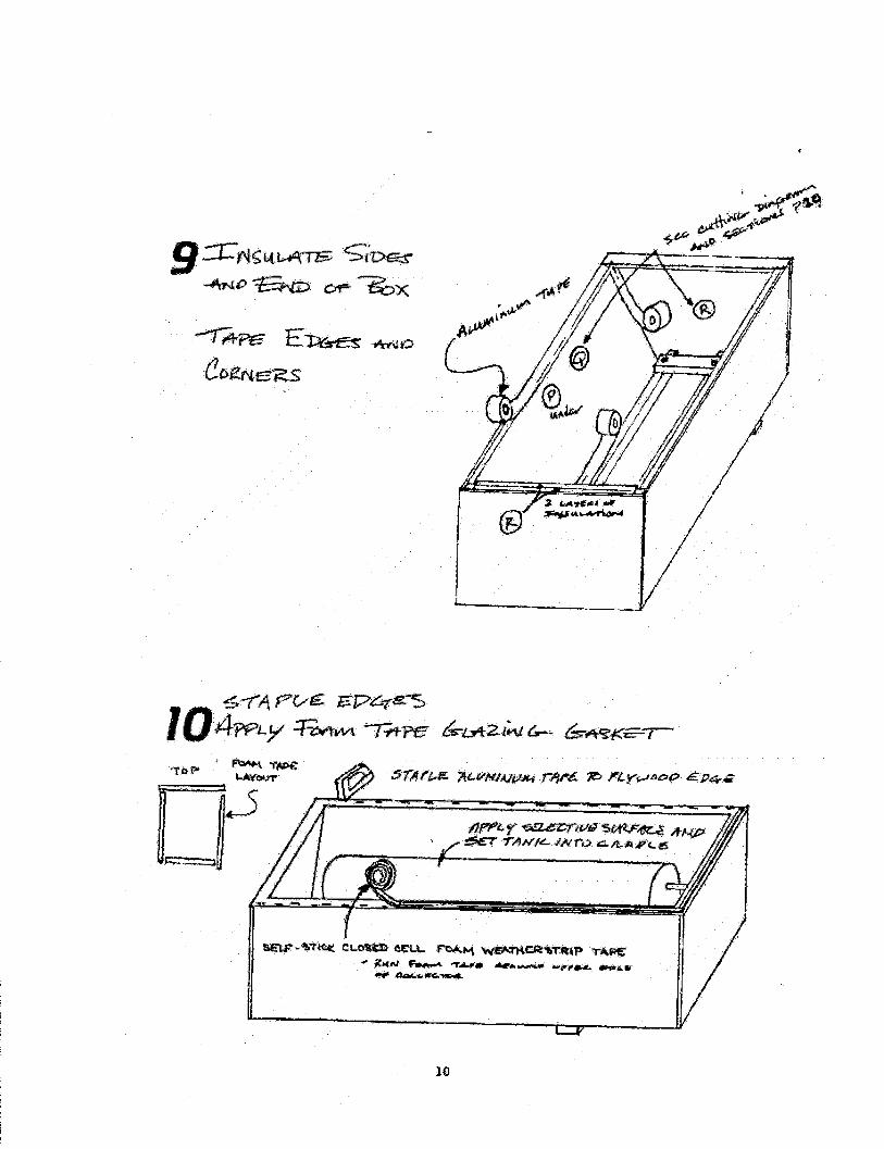
'l-PE Et
10

jJEFjt FE
ca &LE7t
rL1S c.A/
7t iAiil
ie k;- -#cw1 7
ç.cjcv..kr
FLA*4 Wrn7DPI2± 7t/

PLUMBING
With the major components in place, the collector and hot water heater, youcan now begin plumbing them together. The, tools required are listed onpage 22.
Examine the Existing Water Heating System
Before starting, become familiar with your existing hot water heater. Therewill probably be at least three pipes connected to the water heater.
Look on the top of the heater for "hot" and "cold" labels where pipes enterthe heater. Find the hot water pipe, which connects the hot water heater tothe various hot water faucets in your house. The pipe draws water from thetop of the tank where the water is hottest.
Find the pressure relief pipe caning out of the tank. It is located either at thetop of the tank or on the aide of the tank near the top. This pipe is usuallyvery short. Screwed on the end of this is a pressure relief valve. This valve isthe safety mechanism that prevents the tank from exploding if too muchpressure builds up. There might be a pipe attached to the relief valvedesigned to carry off the steam or superheated water in the event of thepressure valve releasing.
Find the cold water supply pipe. Follow this cold water pipe away from thetank, there should be a gate valve (valve #6, Figure 6, page 13) before thepipe disappears into a wall or under the house. Closing this valve shuts offthe incoming city water and relieves the entire hot water system of the citywater pressure. This valve needs to be closed before any plumbing workstarts. (Note: Always turns off the electricity or gas to the hot water heaterwhenever working on it.)
It is the cold water supply pipe that will be tapped into when installing thisbatch collector. Some hot water heaters have only the hot and cold inlets,the relief valve being placed in the hot water line leading to the house. Asolar hookup can be done equally well with either system.
Tapping into the cold water supply line
For ease of installation and freeze tolerance, all of the new plumbing shouldbe done with 3/4 inch polybutylene pipe. Before making final plumbingconnections between the various components in the system, it is stronglyrecommended that all the pipes and fitting be assembled to ensure proper fitBEFORE they are connected up.

Refer to Figure 6 as the new plumbing requirements are explained. Betweengate valve #6 which shuts off the city water pressure, and the cold entryopening to the water heater, two I fittings and three new gate valves (Nos.1,2, & 3) as shown on Figure 6 must be installed. Valves #2 and #3 willnormally be open. Valve #1 will be closed. Closing valve #2 and #3 andopening valve #1 will isolate the entire solar system from the city pressure,but allow the existing hot water system to function.
Plumbing to the Batch Collector
Cold City water will go directly to the collector. The cold water supply pipegoing to the collector should start at valve #2 and run to the inlet nipple atthe lower end of the first collector. The return pipe run between the batchcollector and the existing water heater starts from the nipple coming out ofthe high end of the last batch collector and ends at valve #3. Valve #3 willnormally be open.
A pressure/temperature relief valve should be placed near valve #3 on thecollector side of the valve. If more than one collector is used, they should beplumbed in series. The upper outlet of the first collector should be connectedto the lover valet of the next collector (see Figure 6).
There should be a drain valve (#5) at the end of the inlet nipple on eachcollector. Their valves ate used to drain the collectors. Valves #4 should beopened when draining the tanks to let air into the system.
A thermometer for monitoring the performance of the system can beinstalled. It should be placed in the return line before it enters the hot waterheater. Thermometers usually come with a 1/2" male screw fitting thatallows easy connection at a t fitting in the plumbing.

Ptgut. 6Piub1 Layout
INSULATION
The performance of a solar hot water system is adversely affected by poorlyinsulated pipes and storage tanks. This is particularly true when pipe runsare long and water heaters sit in unheated areas.
Insulating Pipes
All plumbing between the solar collector and water heater must be insulated.It is especially important that all outdoor piping be insulated. In theWillamette Valley, R3.5 is the minimum R value recommended. For Centraland Eastern Oregon sites, a minimum of R7 should be used. To extendsystem performances into the cold December and January months, consideradding a layer of Ru fiberglass batt insulation to the pipe insulation listedbelow. Burying insulated pipe below the frost line can also reduce pipefreezing and improve the looks of the installation especially if the collectorsare not adjacent to the house. A waterproof cover, such as flexible blackplastic drainpipe, should be used to cover fiberglass insulation or buriedpipes.
3 4

There are several types of pipe insulation available. The insulation will bemade either to slide over the pipe or to clamp around it. In either case, theinsulation is available for various pipe diameters. Pipe insulation exposed tothe weather must be protected. The following table is a guide to severallocally available pipe insulations:
Brand Wall WeatherName value/Inch Thickness Protection
Microlok needs PVC orRigid Fiberglass 3.0 1650 metal jacket
needs latex paint;.Elastomer 3.5 3/4" or PVC or metal
jacketneeds latex paintPolyethylene Zipcote 3/4" or PVC or metal(closed cell) Imcoaflex jacket
Type
Elastomers.
Elastomer insulation comes without slits and should be put on the pipes asthe plumbing is done. Cut the insulation tube slightly longer than the pipe tobe insulated. Slide onto the pipe and join by butting, Use visegrips to holdback the insulation while soldering. Use the manufacturers recommendedadhesive to seal the joints. Elastomer insulations will have to be doublelayered to get the recommended R4 insulation values. When layering theinsulation is sure to stagger the points. Elastomer will deteriorate rapidlywhen exposed to weather or soil. They must be protected. If paint is used itshould not be oil base end it should be reapplied every 35 years.
Fiberglass, Urethane and Isocyanurate.
These types of insulation can be bought in preformed halves. They must beprotected from the weather by a watertight PVC or metallic jacket. The slitsin the jacket should be positioned on the downward side of the pipes andtaped over with water proof, weather resistant tape. Pressure tests theplumbing before insulating.
Arm afi exRu bstax
comes with PVCUrethane 7.0 1"
Solar 7Insultec
4.1
Jacket

Insulating Storage Tanks
The water heater tanks should be insulated to at least Ru. Checkmanufacturer literature to see if the tank is already insulated to this level. Ifnot, it is necessary to add an insulating jacket. Ru fiberglass batts,wrapped around the tank and secured with duct tape, work well. ManyOregon utilities provide free water heater wrap services.
OPERATION AND MAINTENANCE
Batch collectors store a large quantity of solar heated water in the collectoritself. Performance of the batch system is improved if hot water is usedduring or at the end of the day. Morning hot water usage is the worstsituation; much of the solar heat is lost during the night.
The entire solar hot water system should be inspected at least once a year.If a thermometer has been installed to record solar collector outputtemperatures, periodic checks are suggested. If temperatures seem low,inspection of the system is advised.
Collectors
The glaring of the collector panels should be cleansed regularly. All exposedwood surfaces should be inspected and repainted or repaired as needed.
Plumbing
Check for leaks around valves and fittings. Cheek pipe insulation to makesure it is tight and has not deteriorated.
Tanks
Drain and flush tanks once a year. Check tank insulation for tight fit.

14' S& 4J QLAi tL 1i
L-k1P t - - )rfrJ )
,
i3

13 OFIFA. rc 2I3tg MutA-1 -rP/
thk1/
rr' Do
c. I.)bP HlLF viM) AJSfl
¶0JL J
I
W?? A'4u-
3qx 7t P#tT
< &.I? F4-.#i krr!q

AI 'Th' 4/(t'(
t4' i 4rt'

i*71I r r i+zt_"f_ O ai-- ,4 IVf-//tI4iE

.-z-
vJk
fl

21
L c/zE 7_ 4qrEAJ ,z
L. tL

MATERIAL LIST FOR ONE BATCH COLLECTOR
3, 2 x 2's 8' long.2, 2 x 4's, 8' long2 sheets, 1/2" Exterior plywood or 7/16" wafer board 4'x 8'(Recommend cutting it according to cutting diagram at place ofpurchase)2 sheets, 1" Foil Laced rigid polyisocyanurate insulation ("Thermax")4'x 8'4 (mm), 12"x 12"x 2" Concrete paving slabs (slopped sites requiremore)1, 34"x 76" Tempered patio door glass (Used or seconds are OK andcheaper)I roll, Aluminum duct board tape (widths between 2" and 4" OK)20', 3/8"x3/16" Self stick closed cell foam weatherstrip tape (17' rolls)10, 1 1/2"x 1 1/2" Galvanized corner angles.2, Joist hangers for 2 x 4's 6, 3" x 3/8" Lag screws with washers1 box (100), 1 1/4" #8 or #10 Zinc plated hex heed sheet metalscrews1 box 1/4" staples1 roll, Plumbers Tape (perforated galvanized metal strapping)1 gallon, Water repellent wood stain (enough for two collectors)1 tube, Paintable caulk1 can, Flat black high temperature stove paint1 New or used water heater (52 gallon preferred 16" or 18" diameter)Selective surface (enough to cover front half of tank, about 2'x 5')Plumbing fittings, 3, 3/4" galv. pipe nipples 5", 6"and 14; 33/4" galv. male plugs (nipples and plugs may vary depending on tank)3/4" galv. elbow;3/4" hose bib; roll of teflon plumbing tape
TOOLS LIST
Hack sawUtility knifeScrew driversTin snipsTape measureCaulking gunHammerShovelPaint brush

3" 'C' clampsScissorsSurformMagnetic compassHand staple gunPliersSandpaperSaw (circular preferred)Variable speed elec. drillDrill bits 3/16", 3/8", and 1 1/8"Screw bit for electric drillPipe clamp over 40" (not mandatory)Level (24" or over)Extension cordGarden Hose (for tank testing)
Selective Black Foil Products
Product Availability Width
Berry SolarProducts2850Woodbridge
Sunsponge Ave.Edison, NJ08837(201) 549-0700
Novamet681 LawlinsRd.Wyckoff, NJ 6"07481(201) 891-7976
SolarComponentsCorpBox 237Manchester,
Absorptance EmittanceCost per Sq. (1.00% = (0%= Ideal)Ft. Ideal)
24" $2.20, 25 sqftmm.
10 ftroll=$2.50/sqft
25 ftroll = $2.40/sqft
0.95 0.10
$2.00 0.97 0.10Ma xo rb
Solar- L-Foil

NH 03105(603) 668-8136
EnergyControlsProducts3M BranchISales Ctr.
:ECP 2000 3130LexingtonAve S.Egan, MN1551211(612) 733-5024
12" 100 ftrolI=$0.80/sqft
Return to SEA of 0 Home Pale
© 200lSolar Energy Association of Oregon. Presented by Oikos: GreenBuUdng Source.