Embed Size (px)
Citation preview
Battalion Bits33 Norway Spruce Street, Stittsville, ON, Canada K2S 1P3Phone: (613) 836-6575, e-mail: [email protected]
Battalion Bits BT8: PzKpfw IV Ausf D
BackgroundThe PzKpfw IV was the heavier of the two standard tanks with which
Germany started the war, and it continued in service with various upgrades through tothe end. Initially fitted with a short 75mm gun as an infantry support vehicle, its largerturret allowed it to carry higher velocity 75mm guns and so continue in service until1945. Its counterpart, the PzKpfw III was limited by its smaller turret although thatchassis remained in service with StuGs until near the end of the war.
The Tamiya kit represents a late model Ausf J, so this resin conversion setallows the builder to backdate this kit to an Ausf D, as used in France, Russia andNorth Africa until about 1942. Early PzKpfw IVs were also upgraded in service soone can mix and match parts a bit to represent variations. The key structuralidentifiers of the D was the stepped front plate, and the mid-series turret with bulgedrear plate and early armoured cupola.
Before AssemblyAs with all resin sets, wash all the parts in a strong detergent and rinse in clear
water to remove any oils or mould releases. Remove pour stubs and clean up theparts; use a mask when sanding resin and wet sand where possible. Cyanoacrylateadhesives work best but quickly; use five minute epoxy if joint requires manipulationwhile setting. These instructions follow the step-by-step kit instructions withvariations where applicable.
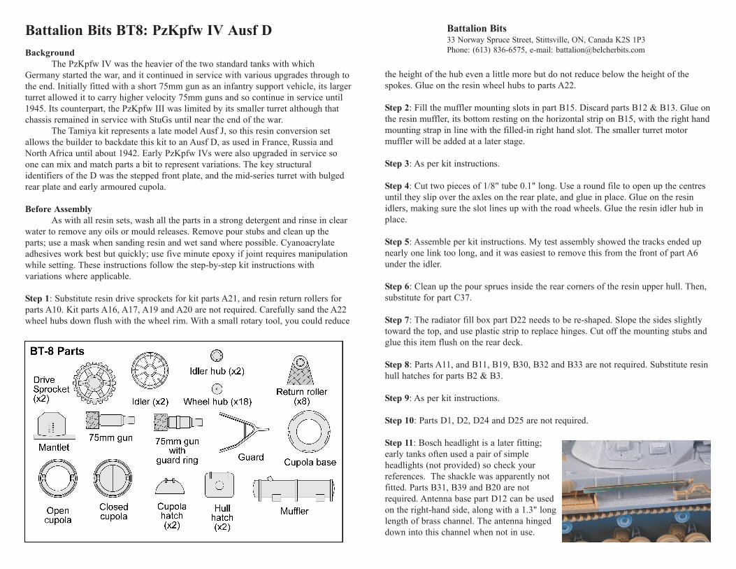
Step 1: Substitute resin drive sprockets for kit parts A21, and resin return rollers forparts A10. Kit parts A16, A17, A19 and A20 are not required. Carefully sand the A22wheel hubs down flush with the wheel rim. With a small rotary tool, you could reduce
the height of the hub even a little more but do not reduce below the height of thespokes. Glue on the resin wheel hubs to parts A22.
Step 2: Fill the muffler mounting slots in part B15. Discard parts B12 & B13. Glue onthe resin muffler, its bottom resting on the horizontal strip on B15, with the right handmounting strap in line with the filled-in right hand slot. The smaller turret motormuffler will be added at a later stage.
Step 3: As per kit instructions.
Step 4: Cut two pieces of 1/8" tube 0.1" long. Use a round file to open up the centresuntil they slip over the axles on the rear plate, and glue in place. Glue on the resinidlers, making sure the slot lines up with the road wheels. Glue the resin idler hub inplace.
Step 5: Assemble per kit instructions. My test assembly showed the tracks ended upnearly one link too long, and it was easiest to remove this from the front of part A6under the idler.
Step 6: Clean up the pour sprues inside the rear corners of the resin upper hull. Then,substitute for part C37.
Step 7: The radiator fill box part D22 needs to be re-shaped. Slope the sides slightlytoward the top, and use plastic strip to replace hinges. Cut off the mounting stubs andglue this item flush on the rear deck.
Step 8: Parts A11, and B11, B19, B30, B32 and B33 are not required. Substitute resinhull hatches for parts B2 & B3.
Step 9: As per kit instructions.
Step 10: Parts D1, D2, D24 and D25 are not required.
Step 11: Bosch headlight is a later fitting;early tanks often used a pair of simpleheadlights (not provided) so check yourreferences. The shackle was apparently notfitted. Parts B31, B39 and B20 are notrequired. Antenna base part D12 can be usedon the right-hand side, along with a 1.3" longlength of brass channel. The antenna hingeddown into this channel when not in use.
Step 12: Not applicable.
Steps 13-17: Not applicable, although many Ausf Ds did use the storage box.
Turret motor muffler: Theturret traverse was poweredby a small motor which had aseparate muffler. Using thephoto below, glue on a smallpiece of 0.080" quarter-roundplastic (supplied) to act as thehull exit. Cut a piece of0.080" diameter rod(supplied) to 0.75" long, andglue where shown. Cut alength of the 0.035" rod to0.05" long and glue to theright-hand end. Bend, cut andfit a length of 0.035" rod on the other end.
Resin Turret Assembly: Clean up the resin turret base and after test fitting into theresin turret, glue together.
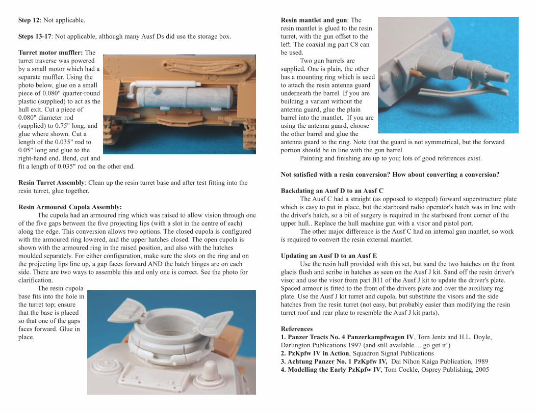
Resin Armoured Cupola Assembly:The cupola had an armoured ring which was raised to allow vision through one
of the five gaps between the five projecting lips (with a slot in the centre of each)along the edge. This conversion allows two options. The closed cupola is configuredwith the armoured ring lowered, and the upper hatches closed. The open cupola isshown with the armoured ring in the raised position, and also with the hatchesmoulded separately. For either configuration, make sure the slots on the ring and onthe projecting lips line up, a gap faces forward AND the hatch hinges are on eachside. There are two ways to assemble this and only one is correct. See the photo forclarification.
The resin cupolabase fits into the hole inthe turret top; ensurethat the base is placedso that one of the gapsfaces forward. Glue inplace.
Resin mantlet and gun: Theresin mantlet is glued to the resinturret, with the gun offset to theleft. The coaxial mg part C8 canbe used.
Two gun barrels aresupplied. One is plain, the otherhas a mounting ring which is usedto attach the resin antenna guardunderneath the barrel. If you arebuilding a variant without theantenna guard, glue the plainbarrel into the mantlet. If you areusing the antenna guard, choosethe other barrel and glue theantenna guard to the ring. Note that the guard is not symmetrical, but the forwardportion should be in line with the gun barrel.
Painting and finishing are up to you; lots of good references exist.
Not satisfied with a resin conversion? How about converting a conversion?
Backdating an Ausf D to an Ausf CThe Ausf C had a straight (as opposed to stepped) forward superstructure plate
which is easy to put in place, but the starboard radio operator's hatch was in line withthe driver's hatch, so a bit of surgery is required in the starboard front corner of theupper hull.. Replace the hull machine gun with a visor and pistol port.
The other major difference is the Ausf C had an internal gun mantlet, so workis required to convert the resin external mantlet.
Updating an Ausf D to an Ausf EUse the resin hull provided with this set, but sand the two hatches on the front
glacis flush and scribe in hatches as seen on the Ausf J kit. Sand off the resin driver'svisor and use the visor from part B11 of the Ausf J kit to update the driver's plate.Spaced armour is fitted to the front of the drivers plate and over the auxiliary mgplate. Use the Ausf J kit turret and cupola, but substitute the visors and the sidehatches from the resin turret (not easy, but probably easier than modifying the resinturret roof and rear plate to resemble the Ausf J kit parts).
References1. Panzer Tracts No. 4 Panzerkampfwagen IV, Tom Jentz and H.L. Doyle,Darlington Publications 1997 (and still available ... go get it!)2. PzKpfw IV in Action, Squadron Signal Publications3. Achtung Panzer No. 1 PzKpfw IV, Dai Nihon Kaiga Publication, 19894. Modelling the Early PzKpfw IV, Tom Cockle, Osprey Publishing, 2005