Embed Size (px)
Citation preview

BATTERY BOOSTER/CHARGERMODEL NO: DIGICAR 900
PART NO: 6261205
OPERATION & MAINTENANCEINSTRUCTIONS
LS0715

P
INTRODUCTION
Thank you for purchasing this CLARKE Battery booster / charger which is suitable for charging and boosting 12 + 24 Volt batteries
Please read this manual thoroughly, before attempting to operate, and carefully follow all instructions given.
It is vitally important that ALL precautions are taken, as specified, which will not only provide protection for yourself and that of others around you, but will also ensure that the Battery Charger will give you long and satisfactory service.
GUARANTEE
This CLARKE product is guaranteed against faulty manufacture for a period of 12 months from the date of purchase. Please keep your receipt as proof of purchase.
This guarantee is invalid if the product is found to have been abused or tampered with in any way, or not used for the purpose for which it was intended.
Faulty goods should be returned to their place of purchase, no product can be returned to us without prior permission.
This guarantee does not effect your statutory rights.
ENVIRONMENTAL RECYCLING POLICY
Through purchase of this product, the customer is taking on the obligation to deal with the WEEE in accordance with the WEEE regulations in relation to the treatment, recycling & recovery and environmentally sound disposal of the WEEE.
In effect, this means that this product must not be disposed of with general household waste. It must be disposed of according to the laws governing Waste Electrical and Electronic Equipment (WEEE) at a recognised disposal facility.
2arts & Service: 020 8988 7400 / E-mail: [email protected] or [email protected]

P
SAFETY PRECAUTIONS
1. To prevent the battery from overheating and consequent damage, use the BOOST facility sparingly and do not exceed our recommendations.
2. Battery acid is highly corrosive. If spillage occurs, wipe off immediately and wash copiously with water. Particularly avoid contact with the eyes.
3. Do not expose this unit to rain.
4. Never touch the negative and positive leads together.
5. Never attempt any electrical or mechanical repair. If you have a problem with your machine contact your local stockist for service information.
6. Before charging ensure the battery terminals are clean, and that the cells are filled with electrolyte to the correct level by adding distilled water where necessary.
7. Where appropriate we recommend that the positive (+) lead to the battery is disconnected on the vehicle prior to charging. This will prevent damaging the vehicle electronics.
8. When charging is completed, ensure that the vehicle battery leads are secured to the correct terminals which should be clean and lightly smeared with petroleum jelly to prevent corrosion. Finally, re check the electrolyte level.
WARNING: BECAUSE HIGHLY FLAMMABLE HYDROGEN GAS IS RELEASED IN THE PROCESS OF BATTERY CHARGING, ALWAYS REMEMBER TO SWITCH OFF FIRST TO AVOID SPARKING, WHICH CAN OCCUR WHEN CONNECTING OR DISCONNECTING LIVE LEADS.
WARNING: CERTAIN TYPES OF SEALED OR MAINTENANCE-FREE BATTERIES NEED EXTRA CARE WHEN CHARGING. PLEASE CONSULT BATTERY MANUFACTURERS INSTRUCTIONS BEFORE USING THIS UNIT.
WARNING: TOXIC FUMES CAN BE RELEASED DURING BATTERY CHARGING, ONLY USE THIS UNIT IN A WELL VENTILATED AREA.
3arts & Service: 020 8988 7400 / E-mail: [email protected] or [email protected]

P
ELECTRICAL CONNECTIONS
Connect the three core mains lead to a suitable industrial supply isolator, or heavy duty plug. These chargers must be connected to a supply having a rated capacity of greater than 13 Amps.
The maximum input current for this unit is 25amps
IMPORTANT: The wires in the mains lead are coloured in accordance with the following code:
As the colours of the flexible cord of this appliance may not correspond with the coloured markings identifying terminals in your plug proceed as follows:
• Connect GREEN & YELLOW coloured cord to plug terminal marked with a letter ‘E’ or Earth symbol ‘’ or coloured GREEN or GREEN & YELLOW.
• Connect BROWN cord to terminal marked with a letter L or coloured RED
• Connect BLUE cord to terminal marked with a letter N or coloured BLACK
If in doubt, consult a qualified electrician.
WARNING: READ THESE ELECTRICAL SAFETY INSTRUCTIONS THOROUGHLY.
WARNING: A 13 Amp (BS1363) plug is not suitable.
WARNING: THIS APPLIANCE MUST BE EARTHED
Green & Yellow Earth
Blue Neutral
Brown Live
4arts & Service: 020 8988 7400 / E-mail: [email protected] or [email protected]

P
ASSEMBLY
FITTING THE WHEELS1. Use the two bolts supplied to fit
the front foot to the base as shown.
2. Fit one of the circlips to the axle as shown.
3. Slide the axle through the wheel (from the outside)
4. Pass the free end of the axle through the two holes on the base.
5. Place the second wheel on the end of the axle.
6. Secure with the second circlip.
FITTING THE HANDLE1. Slide the handle into position as
shown.
2. Secure using the four screws provided.
5arts & Service: 020 8988 7400 / E-mail: [email protected] or [email protected]

P
NOTES ON CHARGING PROCEDURE
LOCATION• Use the battery charger only and exclusively indoors;
• The premises must be well-ventilated;
• The premises must be dry and dust-free;
• The air vents should be free of obstructions;
• The battery charger should be placed on a stable surface.
WARNING: NEVER ATTEMPT TO RE-CHARGE NON-RECHARGEABLE BATTERIES.
6arts & Service: 020 8988 7400 / E-mail: [email protected] or [email protected]

P
CHARGING MORE THAN ONE BATTERY AT THE SAME TIME
If it is necessary to charge more than one battery at the same time, they can be connected in series or in parallel.
• Connection in series is preferred because this makes it possible to monitor the current circulating in each battery, this will be shown on the display.
• Please foillow the diagram below.
WARNING: DO NOT CHARGE BATTERIES WITH DIFFERENT CAPACITIES OR DIFFERENT TYPES OF BATTERIES AT THE SAME TIME.
7arts & Service: 020 8988 7400 / E-mail: [email protected] or [email protected]

P
OVERVIEW
1 ON/OFF Switch
2 Green LED Lights up when the battery charger is connected to the mains supply
3 Yellow LED Lights up when the Overtemperature protection activates
4 Battery Type Selector Pb/Gel, Ca/Ca or AGM
5 Charge Process Selector Automatic or Floating
6 Charge Current / Charge time selector
7 Charge Current / Time adjustment knob
8 Charge Start / Stop button
9 Boost Start / Stop button
10 Voltage / Charge percentage display: Shows either the battery voltage or the charge percentage.
11 Current / Timer display Shows the charge current and the remaining charge time
12 12V / 24V Positive Cable Socket
13 Protection Fuse
14 Negative Cable
15 Positive Cable
8arts & Service: 020 8988 7400 / E-mail: [email protected] or [email protected]

P
BATTERY CHARGING
NOTE: The charging process only activates if the battery connected has a minimum voltage of 7.5V For 12V batteries: 18V For 24V batteries. If the voltages are lower then this or if you want to charge a fully discarged battery or, See “FORCED CHARGING” on page 12.
1. Connect the battery charger to the mains.
2. Switch ON the battery charger using the on/off switch.
• The green led (2) will light up.
SELECT THE BATTERY TYPE
3. Press the battery type selector (4) to select the battery type.
• This battery charger can be used with normal Lead batteries (sealed or unsealed), GEL, AGM batteries or calcium batteries.
NOTE: If you are not sure of the battery type, select calcium battery.
SELECT THE CHARGING PROCESS
4. Select the charging process (5): Automatic or Floating.
AUTOMATIC
• This mode will perform a full charge (at the set current) until the set time has elapsed.
• The charger will then stop and the display will show “END”.
• If you then turn the adjustment knob the display will then show the set charge current.
• If the charging time has not been set, the charger will run for 9,9 hours (the maximum default value).
• To stop the charge before the set time, just push the Charge start / Stop button.
9arts & Service: 020 8988 7400 / E-mail: [email protected] or [email protected]

P
FLOATING:
• This mode will perform a full charge (at the set current) until the set time has elapsed.
• The charging current will decrease to a lower fixed current. A buzzer will signal the transition from full charge to floating charge.
SELECT THE CHARGE CURRENT
5. Press the charge current/time selector (6) until the charge current LED lights up:
6. Turn the adjustment knob (7) to set the desired charge current.
• The current value will be shown in the bottom display (11).
• You should set up a value that is 10% of the battery capacity. For example, if you have a 140Ah battery you should set up 14A.
• This battery charger allows you to set up any value of current from 1 Amp to the maximum rated amperage of the battery charger.
SELECT THE CHARGE TIME
7. Press the charge current/time selector (6) until the charge time LED lights up.
8. Turn the adjustment knob (7) to set the desired charge time.
• The current value will be shown in the bottom display (11).
9. Connect the red cable to the required 12V/24V positive socket.
• Insert the plug on the cable into the socket (12) on the front of the battery charger and then turn the plug clockwise in order to lock it in place.
• Make sure the socket selected is correct for the battery being charged.
10. Connect the clamp on the red cable to the positive terminal of the battery.
10arts & Service: 020 8988 7400 / E-mail: [email protected] or [email protected]

P
11. Connect the clamp on the black cable to the negative terminal of the battery.
• If all connections are correct, the top display will show the battery voltage and the charge status of the battery (expressed in %. 99% means that the battery is full).
• If you have not made the right connections the top display will show the wording “Alb”: double check the battery voltage and connect the red cable to the right positive socket.
• If the battery charger is not connected to a battery, the display will show “StB” (stand by).
• If after connecting the battery, the display shows “StB” and charging is not activated (by pressing the charge start/stop button), it means that the battery is fully discharged, short-circuited or interrupted.
• To charge a fully discharged battery, See “FORCED CHARGING” on page 12.
START CHARGING
12. Check if all the parameters that you set are correct and push the charge start/stop button (8) to begin charging.
• During the charge you cannot change any of the settings.
• To change a setting, you must push the charge start/stop button (8) to STOP the charge.
• After you have changed the settings, you can start the charging process again by pushing charge start/stop button again.
DURING THE CHARGE
• The top display (10) will show the actual voltage value of the battery.
• The bottom display (11) will show the charging current and the remaining charge time alternately.
11arts & Service: 020 8988 7400 / E-mail: [email protected] or [email protected]

P
FORCED CHARGING
Use forced charging if the battery voltage is below7.5V For 12V batteries or 18V For 24V batteries.
1. Connect the battery charger to the mains.
2. Switch ON the battery charger.
3. Connect the black cable to the minus terminal of the battery
4. Connect the red cable to the required 12V/24V positive socket.
• Insert the plug on the cable into the socket (12) on the front of the battery charger and then turn the plug clockwise in order to lock it in place.
• Make sure the socket selected is correct for the battery being charged.
5. Connect the clamp on the red cable to the positive terminal of the battery.
6. Select the type of battery, the type of charge and the charge current as described in the previous section.
7. Ensure that the cables are securely fixed to the battery terminals and hold the charge start/stop button (8) till the top display shows “24” and the bottom display shows “12”.
8. Select the charge voltage.
• Press the battery type selector button (4) for 24V or
• Press the charge current selector button (6) for 12V.
9. Charging will start 1 second after the charge voltage selection.
NOTE: Charging can be stopped at any time by pressing the charge start/stop button (8) again.
NOTE: To reactivate the security functions, turn the charger off and on again.
WARNING: WHEN YOU FOLLOWING THE PROCEDURE BELOW, CERTAIN SAFETY CHECKS ARE DISABLED (CHECK FOR SHORT-CIRCUITED BATTERY AND CORRECT CONNECTION). PAY EXTRA ATTENTION TO THE POLARITY OF THE CONNECTIONS AND THE BATTERY VOLTAGE.
12arts & Service: 020 8988 7400 / E-mail: [email protected] or [email protected]

P
OPERATION AS BOOST STARTER
This battery charger is equipped with a boosting system that will let you start your car without damaging the electronics on board your vehicle.
THE CORRECT PROCEDURE TO BOOST YOUR CAR IS:
1. Connect the black cable to the minus terminal of the battery.
2. Connect the red cable to the required 12V/24V positive socket.
• Insert the plug on the cable into the socket (12) on the front of the battery charger and then turn the plug clockwise in order to lock it in place.
• Make sure the socket selected is correct for the battery being charged.
3. Connect the clamp on the red cable to the positive terminal of the battery.
4. Connect the battery charger to the mains. Check that the socket is equipped with protection fuses or circuit breakers. Switch ON the battery charger: the green led will light.
5. Before starting the boosting procedure is advisable to perform a fast charge with the maximum current for 10-15 minutes.
WARNING: BOOST STARTS MUST BE PERFORMED WHEN THE BATTERY IS STILL MOUNTED ON THE VEHICLE. IT IS SUGGESTED TO PERFORM A NORMAL CHARGE AT THE MAXIMUM CURRENT FOR 10/15 MINUTES BEFORE YOU TRY TO BOOST YOUR CAR.
WARNING: THE BOOST PROCESS ACTIVATES ONLY IF THE BATTERY CHARGER IS CONNECTED TO A BATTERY THAT COMPLIES WITH THE FOLLOWING MINIMUM VOLTAGE VALUES: MORE THAN 7.5V FOR 12V BATTERIES: MORE THAN 18V FOR 24V BATTERIES.
13arts & Service: 020 8988 7400 / E-mail: [email protected] or [email protected]

P
6. Push the boost start/stop button (9) and then try to start the car.
• The battery charger will start to supply energy to the battery.
• If the boost is not successful, wait a few minutes and try again.
• To prevent damage to your battery, the boost function will not be carried out if the battery is damaged (short circuit or broken elements).
• If the Overtemperature protection activates, the yellow LED (3) will light up and the battery charger will not work until it has cooled sufficiently.
7. Once the car starts, the battery charger will automatically stop supplying current. Press the boost start/stop button (9).
8. Disconnect the cables from the battery and replace the battery caps
9. Switch OFF the battery charger, disconnect it from the mains supply and store it in a dry place.
14arts & Service: 020 8988 7400 / E-mail: [email protected] or [email protected]

P
SPECIFICATIONS
Input Voltage 230V @ 50-60Hz
Input Power 1800W
Output Voltages (Battery Voltages) 12V, 24V
Max charging current 50 A
Charging current according to EN norms 40 A
Max boosting current 550 A
Boosting current with 1V/cell 380 A
Max battery size to be charged in 15 hours 750 Ah
Product Dimensions 320 x 487 x 745 mm
Weight 33.5 kg
15arts & Service: 020 8988 7400 / E-mail: [email protected] or [email protected]

P
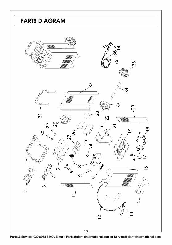
PARTS LIST
No DESCRIPTION PART NUMBER
01 FRONT FRAME EM21690657
02 FRONT PANEL LABEL EM77650259
03 INSERT EM21690658
04 LABEL EM77650260
05 CONTROL PANEL EM33710589 9005
06 FEMALE DINSE PLUG EM22100002
07 SWITCH EM22205009
08 RECTIFIER EM22400130
09 PROBE EM26075013
10 300A FUSE EM22220011
11 LEFT SIDE PANEL EM33705669 3020
12 BLACK CHARGING CABLE EM43200072
13 FUSE BOX COVER EM21690110
14 KIT CLAMPS RED-BLACK EM04600407
15 PLASTIC FOOT EM337402809005
16 FRONT PANEL EM33700733 3020
17 CABLE CLAMP EM04600234
18 MAINS POWER CABLE EM20220022
19 LOWER PANEL EM33700339 3020
20 RIGHT PANEL EM33705668 3020
21 TRANSFORMER EM44105088
22. THERMOSTAT VEBE 100Ø SUPPORT EM04600261
23 CONTACTOR EM22225006
24 COMPLETE THERMOSTAT 100Ø + SUPPORT EM04600113
25 PCB SUPPORT EM33640455
26 POWER PC BOARD EM22700037
27 CONTROL P.C.BOARD EM22700036
29 KNOB FOR RED SWITCH + INDICATOR EM04600268
30 KNOB EM21690549
31 HANDLE EM33725114 9005
32 BACK PANEL EM33715190 9005
33 WHEEL EM21625051
34 AXLE EM55200016
35 DINSE PLUG EM22100021
36 RED CHARGING CABLE EM43200073
18arts & Service: 020 8988 7400 / E-mail: [email protected] or [email protected]