Embed Size (px)
Citation preview

1
Battery Selection, Safety, and Monitoring in Mobile Applications
Yevgen Barsukov
Texas Instruments
22006 TI Portable Power Seminar
Agenda
IntroductionBattery Charging / Discharging characteristicsSelf- discharge / AgingCharging algorithm/Charge TerminationSpecial requirementsMain applicationsAdvantages and LimitationsBattery Treatment

2
32006 TI Portable Power Seminar
Principles of Chemical Power Source
Vdis
Vch
Cathode Anode
Vdis
Vch
Cathode is aggressive oxidizing agent (like oxygen, MnO2, NiO(OH)). It really likes to rip electrons from anything near it
Anode is a willing donor of electrons, a reducing agent like hydrogen, Zn, Cd, Pb. It has excess electrons to give.
When both are electrically connected, spontaneous electron flow from anode to cathode occurs. Ions move in electrolyte to keep electric neutrality
e-
C+
Electrolyte
-+
R
Ion+
42006 TI Portable Power Seminar
Battery Electrical Equivalent Circuit
I.RBAT
CapacitorCapacitor + resistorBattery
Constant current discharge,transient effect
ONOFF
Cathode AnodeElectrolyte
Separator
+ -
Positiveelectrode
Negativeelectrode
Battery AC modelCathode
+ CBAT RBATAnode
-
Battery DC model

3
52006 TI Portable Power Seminar
Battery Chemical Capacity
EDV=3.1V/cell
Qmax
• Battery capacity (Qmax) is defined as amount of charge which canbe extracted from the fully charged cell until its voltage drops below end of discharge voltage (EDV).
• EDV is minimal voltage acceptable for the application or for battery chemistry, whichever is higher.
Load current: 0.2C
CBAT RBAT
Battery Capacity: 1CDischarge rate 1C:Current to completely discharge a battery in one hourExample:2200mAh battery, 1C discharge rate: 2200mA
3.6V (Battery rated voltage)
1 2 3 4 5 60
3.0
3.5
4.0
4.5
Capacity, Ah
Voltage, V
62006 TI Portable Power Seminar
Useable Capacity
If high current is flowing through the battery, EDV will be reached earlier because of I*RBAT voltage drop.External battery voltage can be roughly modeled as V=V0CV-I*RBAT where RBAT is internal resistance of batteryUseable capacity Quse of battery is capacity at given load I. Quse is less then Qmax
EDV
QmaxQuse
I*RBAT
0 1 2 3 4 6
3.0
3.5
4.0
4.5
Capacity, Ah
Voltage, V CBAT RBAT
VOCV
+ - I
+ -V=V0CV - I*RBAT

4
72006 TI Portable Power Seminar
Battery Impedance and Cycle Life
During repetitive charging/discharging usable capacity is decreasing
It is common to define cycle life of battery as number of cycles when useable capacity decreases below 70% of original.
Depending on chemistry, different factors are influencing degradation. Common factors for all batteries are high charge rate and high temperature.
Battery AC model
82006 TI Portable Power Seminar
Safety and Thermal StabilityIncreased temperature can not only accelerate degradation, but it can cause thermal run-away and battery explosion
This is a specific concern with Li-ion battery, but other batteries are also capable to explosive self-heating
Rapid temperature increase can happen if battery is overcharged at high current or shorted
During overcharge of Li-ion battery very active metallic lithium is deposited on anode. This material highly increases the danger of explosion
Material developments are ongoing to increase thermal runaway temperature.
Thermal runaway

5
92006 TI Portable Power Seminar
NiCd Rechargeable Battery
102006 TI Portable Power Seminar
NiCd Reactions
Discharge: Minimum 0.7VThe positive electrode is converted from nickel oxyhydroxide to nickel hydroxideThe negative electrode is converted from Cadmium to Cadmium hydroxide
Charge: Maximum 1.6V, average operating voltage: 1.2VThe reverse reaction occurs during chargeToward the end of charge the reaction efficiency decreasesOvercharge produces oxygen which then produces heat as it exceeds the electrode recombination rateCharge termination is -dV~10mV, dT/dt~1°C/min. At low rate no –dV/dt will occur, therefore termination by timer, temperature of capacity count is needed.

6
112006 TI Portable Power Seminar
NiCd Charging
122006 TI Portable Power Seminar
NiCd Discharging Characteristics
*http://www.buchmann.ca
CBAT RBAT
VOCV
+ - I
+ -V=V0CV - I*RBAT
Good characteristics for high discharge rate due to low internal impedance

7
132006 TI Portable Power Seminar
NiCd Self-Discharge
• Aged battery has higher self-discharge rate
142006 TI Portable Power Seminar
Advantages and Limitations: NiCd Battery
Advantages:
• Fast and simple charge: constant current charge
• High number of charge/discharge cycles >1000
• Good low temperature discharge capacity: 80%@-200C
• Low internal impedance
• Simple transportation
• CheapDisadvantages• Low energy density: 70Wh/kg (90Wh/kg: NiMH; 200Wh/kg: LI-Ion)
• Memory effect: Need periodically deep discharge to recover capacity
• Relatively high self-discharge at high temperature
• Environmentally unfriendly: Contains toxic metals

8
152006 TI Portable Power Seminar
Treatment of NiCd battery
Healthy habits:Most stable in discharged state. However , due to fast self-discharge, to prevent over discharge should be placed for storage in charged state.If used in application needing prolonged trickle-charge (stand-by), should be periodically fully discharged
Degradation mechanisms: Voltage depression. Cathode material changes into inactive crystalline form when stored in charged state. Prevention –discharge regularly. Repair: Charge/discharge several times to 0.7V. For cases of severe capacity loss, keep at 0.7V for prolonged time (24 hrs)
162006 TI Portable Power Seminar
Nickel-Metal-Hydride (NiMH) Battery

9
172006 TI Portable Power Seminar
NiMH Reactions
Discharge: Minimal 0.7VThe positive electrode is converted from nickel oxyhydroxide to nickel hydroxideThe negative electrode is converted from a Metal Hydride to Metal plus Water
Charge: Maximal 1.6VThe reverse reaction occurs during chargeWhen the Metal is converted to a Metal Hydride, heat is produced. Towards the end of charge the reaction efficiency decreasesOvercharge produces oxygen which then produces heat as it exceeds the electrode recombination rateCharge termination: PVD<-5mV, dT/dt~1°C/min. Might not occur at low charge rate
Average operating voltage: 1.2V
182006 TI Portable Power Seminar
NiMH Battery Charge Characteristics
At the End of Charge • Cell voltage drop, but not significant• Cell temperature Increase Charge termination
1 C
1 C
0.5 C
0.5 C 0.1 C
0.1 C

10
192006 TI Portable Power Seminar
NiMH Discharging Characteristics
• End of Discharge Voltage=EDV=1.0V/cell• Lower useable capacity at high discharge rate due to IR drop
VBAT=VOCV – I RBAT
EDV=1.0V
CBAT RBAT
VOCV
+ - I
+ -V=V0CV - I*RBAT
1 C
0.2 C
3 C
202006 TI Portable Power Seminar
NiMH Discharge under Different Temperatures
•No discharge capacity at -200C

11
212006 TI Portable Power Seminar
NiMH Self-Discharge Characteristics
• Self-Discharge 2.5%/day at 25C• Higher T, Higher Self-discharge
1200
1000
800
600
400
200
0
Capacity mAh
0 10 20 30 40 50 60 70Time: Days
150 C
250C
350C
450C
222006 TI Portable Power Seminar
Advantages and Limitations: NiMH Battery
Advantages:• Fast and simple charge: constant current charge
• 50-100% more capacity/energy than NiCd
• Environmentally friendly: Contains only mild toxic metals
• No transportation regulation
• Cheaper than Li-Ion, but 20% more expensive than NiCd
Disadvantages
• Limited service life cycles: 400-500
• High self-discharge at high temperature (30% per month)
• High maintenance: regular full discharge to prevent voltage depression
• Generate more heat during charge than NiCd

12
232006 TI Portable Power Seminar
Treatment of NiMH Battery
Healthy habits:Most stable in discharged state. If used in application needing prolonged trickle-charge (stand-by), should be periodically fully dischargedAvoid high temperature as corrosion accelerates and charge efficiency drops
Degradation mechanisms: Voltage depression. Cathode material changes into inactive crystalline form when stored in charged state. Less expressed compared to NiCd because of newer technologies used in cathode material and electrolyte preparation. Prevention – discharge regularly. Repair: Charge/discharge several times to 0.7V. For cases of severe capacity loss, keep at 0.7V for prolonged time (24 hrs)
242006 TI Portable Power Seminar
Li-Ion Rechargeable Battery

13
252006 TI Portable Power Seminar
Li-Ion Battery Construction
Separator: Melt at 1500 CPositive Electrode: LiCoO2 (200um)Negative Electrode: Carbon (100-200um)Current Collector: Cu (Anode)-20um
Al (Cathode)-20umCasting: Steel
262006 TI Portable Power Seminar
Li-Ion Intercalation
Cathode: LiCoO2 Anode: Carbon

14
272006 TI Portable Power Seminar
Li-Ion Chemistry
Discharge: Minimum 2.7VLi ions leave carbon matrix and are adsorbed by LiCoO2 matrix
Charge: Maximum 4.1(Coke Anode) or 4.2V(Graphite)Li ions are extracted from LiCoO2 and are intercalated into carbon matrix. Li-carbon intercalation compound is extremely active, therefore only organic electrolytes can be used. Contact of interiors with air or water destroys the battery.
Specified Cell voltage: 3.6V
Cathode +
Anode +
282006 TI Portable Power Seminar
Li-Ion 18650 Charging: CC/CV
CC Mode
CV Mode

15
292006 TI Portable Power Seminar
Charge VoltageThe voltage between the charging terminals should be no more than 4.20 V (Set this at 4.20 V (max) after taking into account fluctuations in power supply voltages, temperature deviations, etc.). The charge voltage varies according to model cell chemistry. Cells with coke based anodes use 4.1V. Check manufacturer’s specifications for charging.
Charge CurrentCurrent should be limited to 1C rate to prevent overheating and resulting accelerated degradation
Li-Ion Charging: Special Requirements
302006 TI Portable Power Seminar
Ambient Temperature of the Battery Pack During Charge0°C to 45°C. Charging at higher temperature results in accelerated aging
Low-Voltage Battery Pack ChargeWhen the voltage per cell is 2.9 V or less, charge using a charge current of 0.1 C rate or less. This is to provide recovery of passivating layer which might be dissolved after prolonged storage in discharged state. It also prevents overheating at 1C charge when partial Cu-deposition on anode shorted cells on over discharge.
Termination of ChargingThe system will determine that the battery is full by detecting the charge current.Stop charging once the current has reached 1/10-1/20C rate. This value can vary between different manufacturers.
Charge TimerA total charge timer and a charge completion timer should be included. Usuallycharging time can be limited to 3-5 hrs.
Li-Ion Charging: Special Requirements (Cont.)

16
312006 TI Portable Power Seminar
• Over charging shortens battery cycle life
Charge Voltage Affects Battery Service Life
4.35V
4.3V4.25V
4.2V
322006 TI Portable Power Seminar
Charge CurrentCurrent should be limited to 1C rate to prevent overheating and resulting accelerated degradation.
“Factors that affect cycle-life and possible degradation mechanisms of a Li-ion cell based on LiCoO2”, Journal of Power Sources 111 (2002) 130-136
Charge Current vs Battery Degradation
1.0C1.1C1.3C1.5C
2.0C

17
332006 TI Portable Power Seminar
C10uF
AC
USB
STAT1
STAT2
USBPG
ACPG
ISET2
ISET1
TMR
VSS
OUT
OUT
OUT
CE
BAT
BAT
TS
LDO
PSEL
DPPM
103AT
RT2
BQ2403x
D1 D2
D4
D3
D6
D5
High: 500mALow: 100mA R1
R2
High: ACLow: USB
3.3V/20mA
HighEnable
System LoadAC Adapter
USB
RT1
R3
• Battery temperature monitoring• Pre-charge, 10% fast charge current, safety timer• Battery Management features maximize battery capacity, cycle life and safety
Linear Battery Charger Example
342006 TI Portable Power Seminar
Li-Ion 18650 Discharge
1/5C1C
2C
Battery AC model
18
352006 TI Portable Power Seminar
Li-Ion 18650 Temperature Discharge Profile
Using organic electrolyte make internal resistance of Li-ion battery more temperature dependent than other batteries.
Self-heat Effect (Internal impedance decrease when T increase)
362006 TI Portable Power Seminar
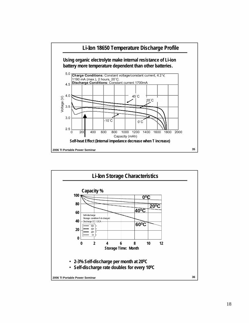
Li-Ion Storage Characteristics
• 2-3% Self-discharge per month at 200C• Self-discharge rate doubles for every 100C
600C
400C200C
00C100
80
60
40
20
0
Capacity %
0 2 4 6 8 10 12Storage Time: Month

19
372006 TI Portable Power Seminar
Li-ion Battery Pack Protection Function
Short Circuit Protection (SCP)
Overcurrent Protection (OCP)
Over Discharge Protection (ODP)
Over Temperature Protection (OTP)
Cell Over voltage Protection (OVP):1st level protection: > 4.25V, Turn off the protection MOSFETs2nd level protection: > 4.45V, blow the fuse
382006 TI Portable Power Seminar
TempSensor
IntegratingADC
CoulombCounting
SMBus
Supply Voltage
Pack +
Pack -
ADCInstantaneous
Voltage
OV, UV, and Safety
HardwareCommunication
32KHzTime Base -Ext/Int Option
Gas GaugeProtection IC
OVP, OCPODP, OTP UVP, SCPbq29330
bq29312AI2C
Li-IonCell
Chemical Fuse
DischargeMOSFET
ChargeMOSFET
SenseResistor10mΩ
Smart Battery Pack Electronics
TI Gas Gauge Chip-set: bq20z80-bq29330; bq2084-bq29312A
bq20z80bq2084

20
392006 TI Portable Power Seminar
Advantages and Limitations
Advantages:
• High energy volumetric and Gravimetric density
• One Li-Ion cell voltage =3 × NiMH or NiCd Cell Volatge
• Low self-discharge: 2-3%/month, double every 100C
• Low maintenance- no periodic discharge is needed, no memory
Limitations:
• Requires Protection Circuit: OVP, OCP, ODP, OTP, UVP, OSP.
• Subject to aging, storing in a cool place, and 40-50% SOC.
• Expensive due to rare Cobalt material and manufacture, 40% higher
in cost than NiCd.
• Subject to transportation regulations
402006 TI Portable Power Seminar
Treatment of Li-Ion Battery
Healthy habits:Most stable in 50% charged state. High voltages accelerate corrosion and electrolyte decomposing. Charging should be limited to maximal voltage specified by manufacturer (4.2 or 4.4 V)Short deep discharge is not detrimental, but long storage in discharge state results in dissolution of protective layer and resulting capacity loss.High temperature is main killer. Take out battery out of notebook to prevent exposure of the pack to high temperatures. Use battery soon after manufacturing. Discharge capacity degrades even if not usedStorage at low temperatures increases shelf lifeIf used in stand-by application, charger should terminate charging and not resume until state of charge drops below 95%. Trickle charging is not recommended.
Degradation Mechanisms: Reaction of Li-carbon compound with electrolyte. Despite protective layer, this reaction is always ongoing and is accelerated by high voltage and high temperature.

21
412006 TI Portable Power Seminar
Overview of Different Chemistries: Energy Density
2-10C3651354.2V3.6VLi-Ion
1-2C246691.6V1.2VNiMH
10-20C200461.6V1.2VNiCd
1-10C103362.7V2VLead-Acid
Dis. RateWh/lWh/kgMax. voltageAvg. VoltageChemistry
422006 TI Portable Power Seminar
Summary
• Review: NiCd, NiMH and Li-Ion battery charge/discharge characteristics
• Battery aging, self-discharging and better treatment practice
• Li-Ion battery charge requirements vs cycle life
• Battery charger, gas gauge and protection ICs should be designed
based on the battery chemistry characteristics

22
Battery Cell Balancing: How to Balance
Yevgen Barsukov
Portable Power Management
442006 TI Portable Power Seminar
Manifestation of the Problem
If two or more cells are connected in series, voltages of each cell diverge during battery use
Voltage difference can eventually bring one of the cell either to unsafe high voltages (explosion danger or early charge termination) or to unsafe low voltages (possible cell degradation).
Voltage differences between the cells can increase when current is applied to the battery, especially near the end of discharge.
Traditional solution was “to fight the symptoms” e.g. trying to reduce voltage difference when it is most noticeable

23
452006 TI Portable Power Seminar
Reasons for Voltage Divergence
State of charge (SOC) differences between the cells
caused by increased discharge of some cell
• internal micro-shorts • external short-term discharge
caused by differences in total cell capacity. Same amount of passed charge causes differences in the SOC
The impedance differences between the cells has an effect on voltage when load is applied
462006 TI Portable Power Seminar
Effect of SOC Unbalance at Battery Voltage
% SOC unbalance remains constant during entire discharge
Voltage differences between the cells vary with state of charge because dV/dSOCvaries with SOC (Fig. a)
Fastest voltage change with SOC is observed near the end of discharge, therefore highest voltage differences at the same SOC unbalance will be observed there
Fig. 1 (a) OCV dependence on SOC (b) OCV differences at different states of charge between
two cells with SOC unbalance of 1%
0 50 1000
500
1000
SOC, %
Dev
iatio
n, m
V
(a)
(b)
0 50 1002
3
4
5
SOC, %
Vol
tage
, V

24
472006 TI Portable Power Seminar
Increased Variation Because of Sharp Impedance Change
Cell impedance increases rapidly near end of discharge
Small differences in SOC cause large differences in impedance near the end of discharge
Because cell voltage is V=OCV + I*R, larger R(SOC) results in much lower voltages for cells with lower SOC
Fig. 2 Voltage differences under C/2 load at different states of chare between cells with 1% of SOC unbalance. Solid line shows differences for OCV case for comparison.
0 50 1000
2000
4000
6000
SOC, %
Dev
iati
on, m
V
482006 TI Portable Power Seminar
Total Cell Capacity Differences
SOC = SOC0 - Qpassed/Qmax
If Qmax1 for cell 1 is larger than Qmax2 for cell 2, the same passed charge Qpassed will result in different SOC1 and SOC2
Total cell capacity can vary due to manufacturing variations
Larger differences develop during battery pack life because of faster degradation of cells exposed to higher temperatures.

25
492006 TI Portable Power Seminar
Impedance Differences from Cell to Cell
Impedance spectra differences between 50 cells in 1 batch for manufacturer (a) and manufacturer (b). Data is shown from 1kHz (left) to 10mHz (right)
Z’(Ohm)
• Impedance at low frequency has main iffect on voltage under load• +-15% deviation of low frequency impedance are typical within a batch of batteries
0 0.062 0.084 0.11 0.13 0.15R(Z) - Ω
-Im
(Z) -
Ω
0.05
0.025
0
10 mHz
1 kHz
Manufacturer (a)
10 mHz
1 kHz
0 0.042 0.064 0.086 0.11 0.13R(Z) - Ω
-Im
(Z) -
Ω
0.05
0.025
0
Manufacturer (b)
502006 TI Portable Power Seminar
Effect of Cell-to-Cell Impedance Variation
Fig. 4 Voltage differences between 2 cells with 15% impedance unbalance at C/2 discharge rates, solid line. Doted line shows difference between the cells with 1% SOC unbalance for comparison.
0 20 40 60 80 1000
50
100
deviation from impedance variationdeviation from 1% disbalance
SOC
Dev
iatio
n, m
V
For new cells impedance can differ by +/-15%.
When current is applied, this will cause either positive or negative voltage shift by I*R
Even at moderate rate of C/2, effect of this difference on voltage exceeds that of the SOC effect
With battery aging, impedance differences from cell to cell increase
Deviation from Impedance variation with C/2Deviation from 1% unbalance

26
512006 TI Portable Power Seminar
Effect of Unbalance on Battery Performance
Increase degradation of a cell with higher SOC during charging due to voltage above recommended 4.2V value.
Increased degradation reduces Qmax, those increasing SOC even more, creating a cycle of self-destruction
Early termination of whole pack charging because of single “high” cell, pack is never charged to full
Discharge capacity is therefore reduced
Early discharge termination if a low SOC cell reaches cell undervoltage threshold before other cells
Useable discharge capacity is reduced
Fig. 5 Individual cell voltage in 4 serially connected cells stack at the end of charge vs. SOC deviation of high cell.
0 5 10 15 20 25 304
4.1
4.2
4.3
4.4
4.5
4.6Low cellNormal cells
Capacity deficiency, %
Cel
l vol
tage
, V
522006 TI Portable Power Seminar
Hardware Implementation of Cell Balancing
Capacitive current redistribution – more complex implementation, no energy loss. Low balancing rate. Moderate size requirements.
Inductive current redistribution – most complex implementation, no energy loss. High balancing rate can be supported. Highest size requirements
Current bypass – simplest method, but some energy loss. Both high and low rates can be implemented. Easy to integrate, small size and cost.

27
532006 TI Portable Power Seminar
Capacitive Charge Redistribution
Charge redistribution eliminates energy loss to overall system
Capacitor charging efficiency of 50% only loses part of the “unbalance energy”.
Energy loss in the switches still has to be considered for thermal management
Difficult to integrate
Small voltage differences at most of SOCs causes low balancing rate
Used mostly in automotive systems due to cost/size
(a)
(b)
Fig. 7 (a) simple capacitor-based shuttle cell balancing circuit (b) shuttle circuit with remote cells connection capability. Reprinted from S. W. Moore and P. J. Schneider, Delfhi application note 2001-01-0959
542006 TI Portable Power Seminar
Inductive Energy Redistribution
Pack energy is transferred into a single cell by directing pack current through a transformer which is switched to one of the cells that needs additional charge
100% coulometricefficiency eliminates energy loss to overall system
Eliminates low balancing rate due to small voltage differences between the cells.
Large size due to use of inductors
Mostly used in automotive applications due to cost/size
Fig. 8 Inductive converter cell balancing circuit. Reprinted from S. W. Moore and P. J. Schneider, Delfhiapplication note 2001-01-0959

28
552006 TI Portable Power Seminar
Current Bypass
Simple implementation of cell-balancing includes a FET placed in parallel with each cell Easy to integrate, for example bq29312Aprotection/balancing IC.Sufficient to counter-act continuous unbalancing processes. Max self-discharge unbalance rate in 3s2p pack is 100uA, while typical 700 Ohm by-pass provides for 2.2mA balancing.External FETs can be used if rapid removal of large unbalance is needed Energy loss occurs during balancing, however it is negligible at the unbalance levels found in portable devices
Balancing controller
R1 R2 R3 R4 R5
Bypassing Current:
FET
CELLbypass R2R1R
VI
++=
Ibypass
RFET
562006 TI Portable Power Seminar
Current Bypass Cell Balance Example: bq29312A

29
572006 TI Portable Power Seminar
Algorithmic Implementation of Cell Balancing
Cell voltage based – turn ON balancing whenever voltage difference is detected
SOC based – measure SOC, assume equal total capacity and turn ON bypass until calculated amount of unbalanced charge is passed.
SOC and total capacity based – measure SOC and total capacity, bypass until calculated amount of unbalanced charge is passed.
582006 TI Portable Power Seminar
Test Results for Cell Voltage Based Balance
Simple implementation
Impedance differences between cells can mislead algorithm
Improved version can only balance near end of charge to reduce effect of I*R drop/rise
More efficient implementation not only compare neighboring cells, but makes decision based on all cell voltages.
Example of implementation: bq2084
Despite the improvements, the need of relying on voltages limits balancing rate to “high difference”SOC regions
Fig. 9 Cell open circuit voltages of 4 cells pack at the end of charge during balancing. Initial unbalance 10%
Cell Voltage at the end of Charge (mV)
4120
4140
4160
4180
4200
1 6 11 16 21 26
Cycle Number
Cell 1
Cell 2
Cell 3
Cell 4

30
592006 TI Portable Power Seminar
SOC and Total Capacity Based
Implementation requires means for measuring SOC for each cell and total cell capacity
Can take advantage of existing gas-gauging solution such as “impedance track” that already has this information
Example implementation: bq20z80
Can balance continuously during charge, discharge or even during inactivity period, regardless of SOC effect on voltage
Independence on voltage differences increases balancing rate about twice
Balancing not distorted by cell impedance differences
0 5 10 15 20 25 304140
4150
4160
4170
4180
cell 0cell 1cell 2
Cycle Number
Cel
l Vol
tage
, mV
Fig. 10 Evolution of cell voltages during SOC/Qmax balancing, starting from initial 2% down (cell 1) and 2% up (cell 2) unbalance
602006 TI Portable Power Seminar
Summary
Cell unbalance can cause significant degradation to battery pack performance
Current by-pass implementation is sufficient for most of cases, but charge redistribution can have advantage in application where energy loss is critical
Voltage difference based algorithms are simply to implement, however are affected by impedance deviations and have lower balancing rate
SOC and total capacity based method achieve best balancing accuracy and rate, but have to relay on already existing

31
Portable Power Battery Management
Texas Instruments
Battery Authentication Architecture andImplementation for Portable Devices
622006 TI Portable Power Seminar
Counterfeit Battery
– Problem: Cheap Replacement Batteries• Functionality Removed• Safety Circuits Removed• Protection Circuit Removed
– Result:• Loss of public confidence in technology• Loss of corporate goodwill• Loss of potential revenue
PACK+
PACK-
Battery Pack
TS
RT: 103AT
Protector
GasGauge
HDQ

32
632006 TI Portable Power Seminar
In General:
A simple and cost effective method to identify and validate identity.
Specific to Peripherals:
A simple and cost effective method to ensure peripherals come from authorized sources.
What is authentication?
642006 TI Portable Power Seminar
• Form factorsStrength: Economies of scaleWeakness: Hard to revise
• LabelingStrength: CheapWeakness: Easily copied & moved around
• User InterventionStrength: Informed consentWeakness: Requires user motivation, difficult to enforce
Current Options

33
652006 TI Portable Power Seminar
Battery Electrical Identification (ID) Scheme
• Fixed Challenge, Fixed Response (ID)• bq2022/23 is an example• Counterfeit by replicating ID through oscilloscope• Adding cost to the system
PACK+
PACK-
SDQ
VSS
VSS
bq2022
SDQ
Battery PackProtector
TSRT: 103AT
CHALLENGER
CommandExpected Answer
RESPONDER
ID Response
Match?
Host System
Battery orPeripheral
AuthenticatedFail
NO YES
662006 TI Portable Power Seminar
Is An ID Approach the Right Choice?
Strength: Requires dedicated electronics• May be cost prohibitive to unauthorized parties
Weakness: Not challenging to reproduce with generic hardware• Static challenge• ID may change from device to device, but only one is needed
to clone.

34
672006 TI Portable Power Seminar
CHALLENGER
ChallengeAuthenticationTransform
Expected Answer
RESPONDER
ChallengeAuthenticationTransform
Calculated Answer
Match?
Yes, thenAuthenticated
No, thenFail
Secret
Secret
Host System
Battery orPeripheral
• Challenge is randomnumber that changeseach time it is transmitted
• Secret can beshared or transmittedsecurely from one side to the other
• More securethan simple ID
• Need extra memory, algorithm development
Random Challenge-Response Authentication Scheme
682006 TI Portable Power Seminar
Is A Challenge/Response Approach The Right Choice?
Strength:• Random from request to request• Introduces a secret, which is known only to the valid parties• The transform may be easily replicated, but the security lies in the
secret.
Weakness:• Requires dedicated secure memory on the host side.• Requires a small amount of additional code development and space,
dependent on the algorithm used.

35
692006 TI Portable Power Seminar
Not a cryptographic functionSimple solution, small footprint, adds some burden to crack
CRC Approach(bq26150)
DisadvantagesAdvantagesAuthentication Transform
Proven cryptographicallyMore complicated algorithm that significantly increases the burden to crack
SHA-1/HMAC(bq26100)
Fixed inputs and fixed outputsSimplest solution, very small footprint, cheapID
(bq2022)
Summary of Authentication Schemes
No ID Simple IDDevice
bq2022
CRC basedAuthentication
bq26150
More SecureLess Secure SHA-1/HMACAuthentication
bq26100
702006 TI Portable Power Seminar
Typical Application Circuit & System Diagram
Gas gauge
Q1 Q2
PACK+
PACK-
HDQ
VCC
VSS
SRP
SRN
BAT
HDQPHDQ
Protector IC
GNDGND
PWR
bq26150HDQHost Process
TI OMAP
Power Management
GPIO
TI Firmware or Customer Firmware
C10.1uF
R15kVSUPPLY
bq27000
Battery Pack
R2100k

36
712006 TI Portable Power Seminar
What If Host Does Not Have Secure Memory?
CHALLENGER Challenge
RESPONDER
ChallengeAuthenticationTransform
Peripheral Answer
Match?
Yes, thenAuthenticated
No, thenFail
Host Answer
Secret
Host System
Battery orPeripheral
Peripheral Answer
RESPONDER
ChallengeAuthenticationTransform
Peripheral Answer
Secret
722006 TI Portable Power Seminar
System dependent• Battery Packs:
– Allow discharge only
• Chargers:– Reduced charging rate
• Other Peripherals– Reduced functionality
May choose to simply log that an unauthorized peripheral was used for warranty information.
What if not authenticated?

37
732006 TI Portable Power Seminar
Optimization of the Charger to System Interaction Enables Increased Handheld
Equipment Functionality
Battery ManagementTexas Instruments
742006 TI Portable Power Seminar
1. Charger and system interactions that affect end equipment performance in commonly used topologies:
- Battery and charger connected to main system power rail
- Power path battery charger
2. Techniques that may be used to improve system performance
- Charger power management- Charger thermal management
3. Summary
Overview

38
752006 TI Portable Power Seminar
Li-Ion Charge CC-CV Profile
IPRECHARGE
3.0V/Cell
Pre-charge
ICHARGE
4.2V/CellFast-charge
ITERMINATION
Taper Current
Battery Voltage
Constant Current Constant Voltage
Pre-chargeTimer Safety Timer
762006 TI Portable Power Seminar
Charging with an Active System Load
ISYS: System load current
System
ISYS+
Adapteror USB
ICHG
IBAT
Charger
ICHG: Charger Output CurrentIBAT: Current going into the battery
(Effective charge current)
If charger is ON ,
with no system load: ICHG = IBAT
with a system load, ICHG = IBAT + ISYS

39
772006 TI Portable Power Seminar
Charger output current is shared: ICHG = IBAT + ISYS
Charging with an Active System Load: Potential Issues
System
ISYS+
Adapteror USB
ICHG
IBAT
Charger
Potential Issues:
Timer faultNo terminationSystem lockup during startup
782006 TI Portable Power Seminar
Issue 1: Pre-Charge Timer Fault
When in Pre-Charge Mode:
1. Charger output current is limited to pre-charge current2. System current “steals” charger output current3. Battery is charged at a very low rate !
Pre-charge timer may expire, turning off the charger
Solution: Keep the system off or in a low-power mode during pre-charge phase !
100mA80mA+
Adapteror USB
System
ICHG ISYS
IBATCharger 20mA

40
792006 TI Portable Power Seminar
Issue 2: Safety Timer Fault
System
ISYS+
Adapteror USB
ICHG
IBAT
Charger
When in Fast Charge Mode:
1. Charger output current is limited to fast charge current2. System current “steals” charger output current3. Battery is charged at a lower rate !
Charge safety timer may expire, turning off the charger
Solution:• Increase the safety timer timeout value• Increase the fast charge current value
700mA
50mA
750mA
802006 TI Portable Power Seminar
Issue 3: System Lockup During Initial Power-Up
System
ISYS+
Adapteror USB
ICHG
Charger
With a battery deeply depleted or no battery connected:
1. System voltage is initially at zero volts (pack open or no battery)2. Charger circuit detects a battery “short” and limits charge current3. System current needed for power-up exceeds available charge current4. System voltage stuck at very low value …..
System never starts
Solution: Reduce system start-up current
30mA10mA

41
812006 TI Portable Power Seminar
Issue 4: Charge Termination NOT Detected
0
0.2
0.4
0.6
0.8
1
20 40 60 80Time
Cu
rren
t (A
)
IBAT
ICHG
ITERM
ISYS
+Adapteror USB
System
ICHG ISYS
IBATCharger
With the charger in regulation mode :
1. Charge current will taper down2. System current exceeds termination threshold3. Charger regulates system rail at charge voltage, ICHG > ITERM
Termination is not detectedCharger safety timer fault
Solution:Disable safety timer or supply additional current to the system
822006 TI Portable Power Seminar
Supplying Additional Current to System
• A new circuit supplies the system load current directly from the input source during voltage regulation ; ICHG ≈ IBAT
• When charging is terminated, the STAT1 pin goes high and disconnects the supplement circuit.
• Design Example: VIN = 5V, VOUT = 4.2V, ISYS = 0.2A, Voltage drop across Rsupplement = 5 - 4.2 = 0.8V, Rsupplement = 0.8 / 0.2 = 4 Ω
QRSupplement
C1uF
IN
VCC
STAT1
STAT2
VSS
OUT
BAT
CE
TTE
ISET
BQ24013
D2
D1
AC Adapter
RSET
SystemVIN
ISYSIsupplement

42
832006 TI Portable Power Seminar
0
1
2
3
4
2.4 2.7 3 3.3 3.6 3.9 4.2
1.24A(1800mAh Li-Ion)
VBAT (V)
700mA(1000mAh battery)
PLOSS (Watt)
Thermal Analysis of the Charger Stage
( ) CHGBATINLOSS I VVP ⋅−=
VIN= 5V+Adapteror USB
System
ICHG ISYS
IBATCharger
Under worst case conditions (high VIN, low BAT) :
1. Charger IC junction temperature is excessive:
Tj = 1300C @700mA, Tj = 192C @1.24A, 500C ambient temperature
Potential oscillatory behavior if charger has thermal shutdownCharger IC damage if charger has no thermal shutdown
Solution: Add thermal management to charger IC !
842006 TI Portable Power Seminar
Time
ICHG
ICHG_THRM
Tj = 1250C
VIN
Thermal Management
Thermal management functions:• Regulate IC junction temperature by reducing
charge current , AND
• Turn off the charger when IC junction temperature
• is excessive
• Slows down the safety timers when the charge current is reduced by the thermal loop, avoiding a false safety timer fault
Common implementations:
• The IC junction temperature is regulated to a value just below the maximum operating junction temperature, 1250C typical
• The charger is turned off when the Charger IC
• junction temperature is excessive, 1500C typical

43
852006 TI Portable Power Seminar
Battery Charger with Thermal Management
• Charger on/off control• Programmable timer – can be disabled by leaving TMR pin floating • Programmable charge current rate• Charger status: pre-charge, fast charge and fault detected• Integrated thermal loop• Charge Safety timer adjusted dynamically when thermal loop is active• Input over-voltage protection
C21uF
IN
TMR
STAT1
STAT2
VSS
OUT
BAT
CE
PG
ISET
bq24061/66
D2
D1
AC Adapter
RSET
System
VINC11uF
862006 TI Portable Power Seminar
Adding Power Path Management to a System
• System power supplied from adapter through Q1• Charge current controlled by Q2• Ideal topology when powering system and charging battery
simultaneously is a requirement• Separates charge current path from system current path• No interaction between charge current and system current
C1
+
-
Adapter
System
Q1 Q2
Powering System
Charging Battery
Controller

44
872006 TI Portable Power Seminar
Power Path Management: Potential Issues
Time
ICHG
VADP
IADP
Adapter current limit
ISYS System Current
Adapter voltage collapses
IADP
C1
+
-
Adapter
System
Q1 Q2
System Current
Charging Battery
ControllerIBAT
ISYS
VOUT
Input current : IADP = IBAT + ISYS
Issues:
• Input voltage collapses
882006 TI Portable Power Seminar
Dynamic Power Path Management (DPPM)
C1
+
-
Adapteror USB
System
Q2CurrentControl
OutputControl
ICHG
IADP ISYS
Time
ICHG
System VoltageVDPPM
IADP AC adapter current limit
ISYS
DPPMMode
System voltage drops if (ISYS + ICHG) > IAC_LIMIT
Large voltage drops due to system load pulses generate undesired ripple at system power rail, causing reset or degrading system performance
DPPM function :
Reduces the charge current when the system voltage is below the user-defined Voltage threshold VDPPM
“Finds” maximum adapter power !!!
Battery Supplement Mode
VBAT

45
892006 TI Portable Power Seminar
• AC adapter or USB port can power the system and charge the battery simultaneously• Dynamically reduces the charge rate to maximize adapter to system current• Battery Supplement enables use of “weak” adapters• Selectable charge current limits : USB 100/500mA, AC adapter up to 1.5A • Battery Management features maximize battery capacity, cycle life and safety
Dynamic Power-Path Management Charger
C10uF
AC
USB
STAT1
STAT2
USBPG
ACPG
ISET2
ISET1
TMR
VSS
OUT
OUT
OUT
CE
BAT
BAT
TS
LDO
PSEL
DPPM
103AT
RT2
bq2403x
D1 D2
D4
D3
D6
D5
High: 500mALow: 100mA R1
R2
High: ACLow: USB
3.3V/20mA
HighEnable
System LoadAC Adapter
USB
RT1
R3
Q1
Q2Q3
902006 TI Portable Power Seminar
bq24032A Test Results
VAC: 1V/div
VOUT: 1V/div
0V
0A
ICHG: 1A/div
IOUT: 1A/div
VDPPM = 4.26V
DPPMMode
DPPMMode
Battery Supplement Mode
AC Adapter Voltage
System Voltage
Battery voltage

46
912006 TI Portable Power Seminar
Summary
• Basic Configuration: system is directly connected to the battery
System rail interacts with battery charger
• Power Path: powers the system directly from the input
Eliminate charger-system rail interaction issues
• Dynamic Power Path Management and battery supplement mode
Prevent system issues during large system current load transients
Prevent battery MOSFET Body-diode conduction during large
system current load transients
Enable use of low cost wall adapters
• Thermal management
922006 TI Portable Power Seminar

47
932006 TI Portable Power Seminar
Circuit Design and Power Loss Analysis of a Synchronous Switching Charger with
Integrated MOSFETs for Li-Ion Batteries
Texas Instruments
942006 TI Portable Power Seminar
• Battery Operated System
• Linear Battery Charger Challenges
• Why Switching Charger?
• EMI Analysis
• Loss Calculation and Analysis
• Switching Charger Example and Measurement
Results
• Summary
Outline

48
952006 TI Portable Power Seminar
+
High Efficiency
DC/DCConverters
CPU Core
LED or LCD
I/O
Memory
BatteryCharger
?
Li-Ion
AC Adapter
Typical Battery Operated System
Digital Circuits
962006 TI Portable Power Seminar
+
AdapterICHG
VBAT
Linear Charger
VIN
Linear Battery Charger
• Simple and low cost.
• Highest power dissipation from pre-charge to fast charge mode transition.
• Ideal for low charge current < 800mA.
• Thermal issue for ≥ 800mA charge current.
• For high charge current applications (Portable DVD, PMP)
( ) CHGBATINLOSS IVVP •−= 0
1
2
3
4
2.4 2.7 3 3.3 3.6 3.9 4.2
1.24A(1800mAh Li-Ion)
VBAT (V)
700mA(1000mAh battery)
PLOSS (Watt)
What’s the solution?
VIN=5.5V

49
972006 TI Portable Power Seminar
Regulate the junction temperature
Thermal fold-back at 1250C by reducing charge current
Drawback: Increase the charge time, may expire the safety timer
Solution 1: Thermal Regulation
ICHG
TLIM
Tj
1250C
ICHG_TLIM
Time
982006 TI Portable Power Seminar
Solution 2: High Efficiency Switching Charger
• Switching Charger: Higher than 90% Efficiency
For VIN=5.5V, VBAT=3.0V, ICHG=1.24A (1800mAh, 0.7C)
• Power Dissipation:
• Ideal for ≥1000mA charge current, high input and output voltage difference
• Typical Applications: Portable DVD Players, MP3 Players,….
18.40C1420CJunction Temp Rise
0.4-Watt3.1-WattPower Dissipation
Switching ChargerLinear Charger

50
992006 TI Portable Power Seminar
L
C
RSNSAdapter
RT
PWM Controller
P-MOSFET
N-M
OS
FE
T
Battery
• Higher Efficiency but Larger Size and Higher Cost Compared to Linear Charger• Small Passive Component Size Needed: Increased Switching Frequency(Consideration #1)• High Switching Frequency: EMI issues (Consideration #2)
Synchronous Switching Charger Design Considerations
• Integrated Power MOSFETs: Smaller Size, Higher Die Temperature• Loss and Thermal Analysis (Consideration #3)
1002006 TI Portable Power Seminar
Inductor Size and Selection
• Low inductance at high switching frequency
CHGripplesIN
BAT
ripple
BATIN I 30%I ,f1
VV
IVV
L =−
= ∆∆
ISATURATION = (1.1-1.5) IPeak, max
,I21
II RippleeargChPeak +=
Design Tradeoff
Higher switching frequency, the smaller the inductor
Higher switching frequency, the higher the switching losses

51
1012006 TI Portable Power Seminar
Total Active Area Size Comparison
50 kHz vs 1.1 MHz Area Comparison
50 KHz Solution1.1 MHz Solution
Bq2410x EVM
1022006 TI Portable Power Seminar
EMI Considerations
EMI DefinitionThe interference of one piece of electronic equipment on the operation of
another by means of electromagnetic energy transfer.
• A generator of electromagnetic energy: (a source)
• Transmission of that energy between equipments: (a coupling means)
• A receptor circuit whose operation is negatively impacted by the
transmitted energy: (a victim circuit)
dtdv
Ci dtdi
Me ==EMI Principles:
Inductive Coupling Capacitive Coupling

52
1032006 TI Portable Power Seminar
Solutions to Reduce EMI
Adding filter (cost! may not work for radiated EMI)
Adding snubber (cost!)
Excellent layout (design difficulty)
Slower switching speed
- No extra cost
- Reduce both conducted and radiated EMI
- May impact efficiency
1042006 TI Portable Power Seminar
Major EMI Source of a Converter
T
VIN
VPH Waveform
High dv/dt and di/dtswitching on the phase node is the major EMI source in a Buck converter
IQ1
TD·T
D·T
IQ1 WaveformIOUT
VPH
VIN
IQ1 IOUT

53
1052006 TI Portable Power Seminar
Why Slower Switching Helps
1us
trise=5ns
1V
1us
trise=100ns
1V
Mag
nitu
de (d
B)M
agni
tude
(dB
)
Mag
nitu
de (d
B)
Frequency
5 6 7 8 9
5 6 7 8 9
Fourier Analysis
Fourier Analysis
100MHz
-175dB
100MHz
-200dB
About 25dB Less!
-100
-150
-200
-250100kHz 1MHz 10MHz 1GHz
-150
-200
-250
-100
100kHz 1MHz 10MHz 1GHz
1062006 TI Portable Power Seminar
CISPR (Europe)FCC
60
0
30
5040
2010
-10100M50M 200M 500M 1G
31dB
Switching Waveforms and EMI Spectrum @ Vin=9V Ichrg=1A
≈7ns
VPH:
≈20ns
VPH:
(dBuV)
(Hz)
After increasing the turn-on time by 3 times (bq24120/123)
Phase node voltage
Phase node voltage
CISPR (Europe)FCC
60
0
30
5040
2010
-10
(dBuV)
100M50M 200M 500M 1G(Hz)
46dB
• 15dB reduction around 150MHz

54
1072006 TI Portable Power Seminar
Loss Analysis: Synchronous Switching Charger
L
Cout
Q1
Q2
• MOSFETs
• Inductor
• RSNS
• Others
Conduction lossesSwitching LossesBody Diode Conduction Losses
Gate Drive Losses
Winding LossesCore Losses
Cap ESR Losses, IC losses …PCB Trace Conduction Losses
Driver and Controller
Cin
+
Resistive losses
RSNS
1082006 TI Portable Power Seminar
MOSFET Conduction Losses
L
C
IQ1 IOUT
Q1
Q2RDSON is a function of temperature, normally increases by 0.39%/°C
+= 22
1 12
1LOUTQ_RMS IIDI ∆
IQ1
IOUT
TD·T
∆IL
DSON2RMSCOND RIP ⋅=
IQ2
IOUT
∆IL
T(1-D)T
+−= 22
2 12
11 LOUTQ_RMS II)D(I ∆
IQ2
MOSFET Q1 MOSFET Q2

55
1092006 TI Portable Power Seminar
Upper MOSFET – Switching Losses
1ON_ISWt∆ 1ON_VSWt∆ 1OFF_ISWt∆
IDS
VDS
Turn-on Q1 Losses Turn-off
SWON_VSWON_ISWL
OUTINQ_swon f)tt()I
I(V.P ⋅+⋅−⋅⋅= 111 250 ∆∆∆
SWOFF_ISWOFF_VSWL
OUTINQ_swoff f)tt()I
I(V.P ⋅+⋅+⋅⋅= 111 250 ∆∆∆
1OFF_VSWt∆
2L
OUT
II
∆− 2L
OUT
II
∆+
INV
111 Q_swoffQ_swonQ_sw PPP +=The total switching losses of Q1:
1102006 TI Portable Power Seminar
Lower MOSFET – Body Diode Conduction & Reverse Recovery Losses
L
C
Q1
Q2
Ibd_Q2
Idrain_Q2
• Relates to the short periods of conduction before and after the on-time of Q2.
• Dead time -- 20–60ns typically
Vbd_Q2Ibd_Q2
Vbd_Q2
SWDTOUTBDQ_BD ftIVP ⋅⋅⋅⋅= 22
SWINRRQRR fVQP ⋅⋅=
QRR

56
1112006 TI Portable Power Seminar
Gate Drive Losses
L
C
Q1
Q2Gate Drive
2Q_DRV1Q_DRVDRV PPP +=
SW1Q_DRV1Q_g1Q_DRV fVQP ⋅⋅=
SW2Q_DRV2Q_g2Q_DRV fVQP ⋅⋅=
1122006 TI Portable Power Seminar
Loss Breakdown @ VIN=12V, VBAT=8.4V, ICHG=1.2A
C o n v e r te r Lo ss B re a k d o w n
0
0 .1
0 .2
0 .3
0 .4
0 .5
0 .6
0 .7
0 .8
1 2 3 4
Lo
ss
es
(W
Ta =2 5 °C
Ta =5 5 °C
FETs
InductorRsns
Capacitor
F ETs Lo ss B re ak d o w n
0
0 .0 5
0 .1
0 .1 5
0 .2
0 .2 5
0 .3
0 .3 5
1 2 3 4 5
Lo
ss
es
(W
Ta =2 5 °C
Ta =5 5 °C
Conduction
SwitchingDriver
Body diode
Qrr
87.4°C208.6°CIC Junction Temperature
32.4°C153.6°CTemperature rise
91.72%57.1%Efficiency
0.911W4.32WTotal Losses
SwitchingTam=55°C
LinearTam=55°C

57
1132006 TI Portable Power Seminar
Typical Applications Circuit
L10µH
RSNS0.1ΩADAPTER (9V or 12V)
RT103AT
PWM Controller
COUT10µF
VBAT
VIN
OUT
20
1
15
14
OUT
SNS
BAT
ISET1
ISET2
8
9
TS 12
VTSB
RT19.31k
1%
RT2442k
1%
RSET1: 7.5k
RSET2: 7.5k
VTSBC2: 0.1µF
C10.1µF
PACK+
PACK-
11
3IN
4
6
CIN10µF
C30.1µF
VSS
VCC
IN
10
2
19
5
7
STAT1
STAT2
PG
TTC
CE16
17
18
PGND
PGND
CELL
D3: Charge
R2: 1.5kΩ D2: Done
D1: Adapter
bq24103
CTTC: 0.1µF
R1:1.5kΩ
R3: 1.5kΩ
Q1
Q2
13
VIN=9V, Battery: 2-cell in series, ICHG=1.25A, Safety timer: 5 hours, IPRECHG = 125mA, Temperature range: 0-45C
1142006 TI Portable Power Seminar
Efficiency - Calculation vs Measurement
VIN=12V, VBAT=8.4V
Iout (mA)
1000 20000 500 1500
Effic
ienc
y (%
)
Calculation Results
100
80
60
40
20
0
Iout (mA)
Effi
cien
cy (
%)
Measurement Results
100
80
60
40
20
01000 20000 500 1500
0 500 1000 1500 2000

58
1152006 TI Portable Power Seminar
Summary
• Linear Charger: Low cost and charge current <0.8A
• Switching Charger: Ideal Solution for higher charge current
• Expensive and complicated compared with Linear Charger
• Reducing the voltage slew rate dv/dt can reduce EMI
• Loss analysis helps thermal design
• Main Applications: Portable DVD Players, PMP……
1162006 TI Portable Power Seminar