Embed Size (px)
Citation preview
Trailer Tire Pressure Monitor System Upfitter Guide
FCA US LLC - Body Builder Instruction All Rights Reserved
07/16/2019 Page 1 of 15
OVERVIEW
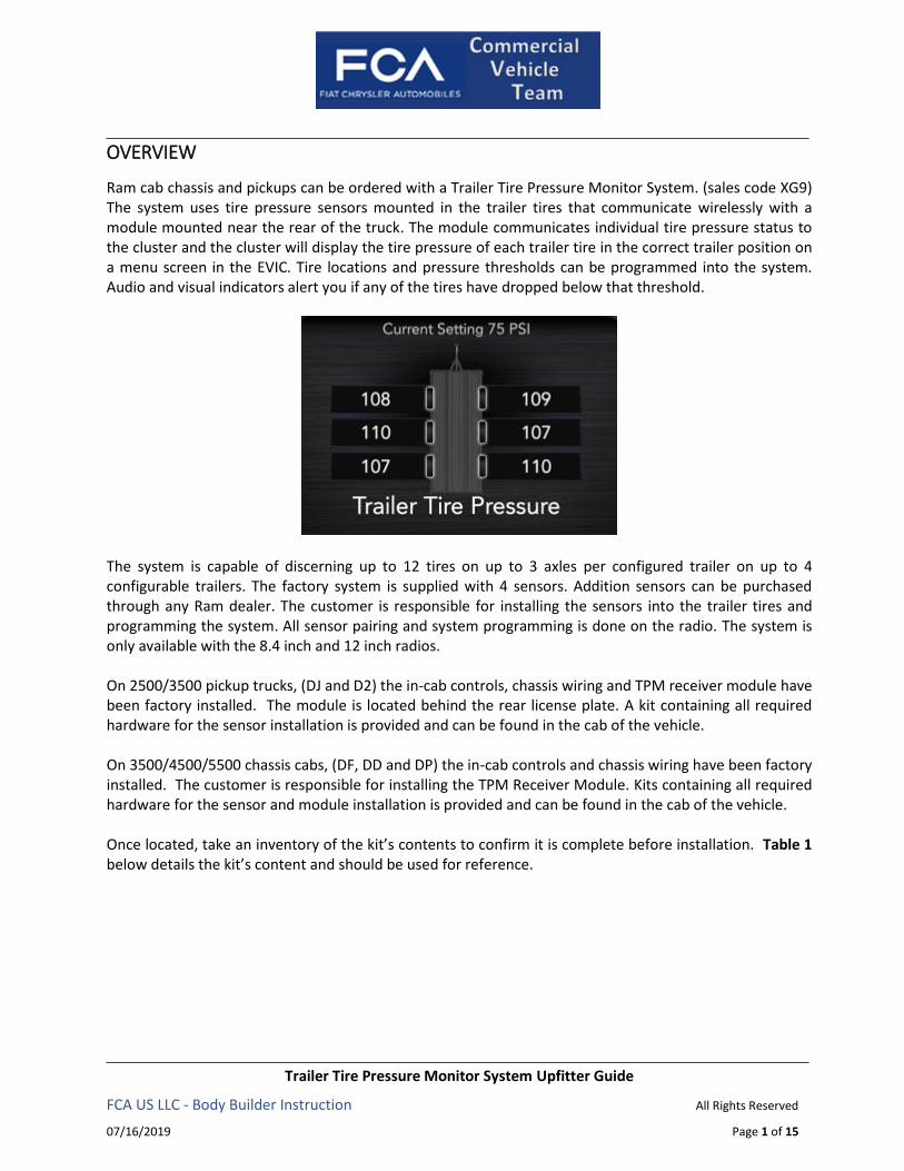
Ram cab chassis and pickups can be ordered with a Trailer Tire Pressure Monitor System. (sales code XG9) The system uses tire pressure sensors mounted in the trailer tires that communicate wirelessly with a module mounted near the rear of the truck. The module communicates individual tire pressure status to the cluster and the cluster will display the tire pressure of each trailer tire in the correct trailer position on a menu screen in the EVIC. Tire locations and pressure thresholds can be programmed into the system. Audio and visual indicators alert you if any of the tires have dropped below that threshold.
The system is capable of discerning up to 12 tires on up to 3 axles per configured trailer on up to 4 configurable trailers. The factory system is supplied with 4 sensors. Addition sensors can be purchased through any Ram dealer. The customer is responsible for installing the sensors into the trailer tires and programming the system. All sensor pairing and system programming is done on the radio. The system is only available with the 8.4 inch and 12 inch radios. On 2500/3500 pickup trucks, (DJ and D2) the in-cab controls, chassis wiring and TPM receiver module have been factory installed. The module is located behind the rear license plate. A kit containing all required hardware for the sensor installation is provided and can be found in the cab of the vehicle. On 3500/4500/5500 chassis cabs, (DF, DD and DP) the in-cab controls and chassis wiring have been factory installed. The customer is responsible for installing the TPM Receiver Module. Kits containing all required hardware for the sensor and module installation is provided and can be found in the cab of the vehicle. Once located, take an inventory of the kit’s contents to confirm it is complete before installation. Table 1 below details the kit’s content and should be used for reference.

Trailer Tire Pressure Monitor System Upfitter Guide
FCA US LLC - Body Builder Instruction All Rights Reserved
07/16/2019 Page 2 of 15
Table 1: Trailer TPM Kit Contents
Quantity Part Number Description Picture
1 52112451AA
Tire Pressure Sensor Kit. (Kit contains 4 -
68375992AA Sensors, hardware & Instructions)
1 68375990AA TPM Receiver Module
(Chassis Cab Only)
1 68395315AB Jumper Harness
(Chassis Cab Only)
TRAILER TPM SYSTEM
System as Delivered
On 3500/4500/5500 chassis cabs, (DF, DD and DP) the in-cab controls and chassis wiring have been factory installed. The module and sensors have not. In the commercial settings menu in the EVIC there will be an enable for the feature. It will be disabled from the factory to prevent DTCs from being set. It can be enabled once the module is installed. On 2500/3500 pickup trucks, (DJ and D2) the in-cab controls, chassis wiring and TPM receiver module have been factory installed. The system is enabled from the factory. There is no feature enable or disable in the EVIC. Since the trailer tire pressure sensors are not installed from the factory, none of the TPM sensors will be paired with the system
Module Installation On 3500/4500/5500 chassis cabs, (DF, DD and DP) the module is installed by the up fitter. It must be mounted in a secure location at or near the center, rear of the chassis. On the pickup truck, it is mounted behind the license plate. It should be mounted in such a way to minimize interference with metal objects between the module and trailer tire pressure sensors. Following these installation guidelines will maximize the range and performance of the receiver module. The module dimensions are shown in Figure 1. It is recommended to use M6 (1/4 inch) weld studs and nuts or M6 (1/4 inch) screws to attach the module to the up fit structure. The recommended torque to be applied on the module is 4 Nm. (35 in-lb.)

Trailer Tire Pressure Monitor System Upfitter Guide
FCA US LLC - Body Builder Instruction All Rights Reserved
07/16/2019 Page 3 of 15
Figure 1
The 68395315AB jumper harness is 10 feet long. One end of the harness plugs into the module and the
other end plugs into a connector at the rear of the chassis. See Figure 2.
Figure 2: Trailer Tire Pressure Monitor Connector Location
After the module is installed, go to the commercial settings menu in the EVIC and enable the trailer tire
pressure monitor system.

Trailer Tire Pressure Monitor System Upfitter Guide
FCA US LLC - Body Builder Instruction All Rights Reserved
07/16/2019 Page 4 of 15
Sensor Installation
The sensors provided for the Trailer TPM system are only intended to be mounted in trailer tires per the installation instructions provided. They cannot be used in any other tire or function. The sensors are rated to read up to 150 PSI. See Appendix A for installation instructions. Instructions are also included in the 52112451AA sensor kit.
Initial Sensor Pairing In order to use this feature, the provided tire pressure sensors must be installed in the desired trailer tires
and the sensors must be paired to the truck. If the target trailer requires more sensors than the four
provided sensors, additional sensor kits or individual sensors can be purchased at an authorized Ram
dealership.
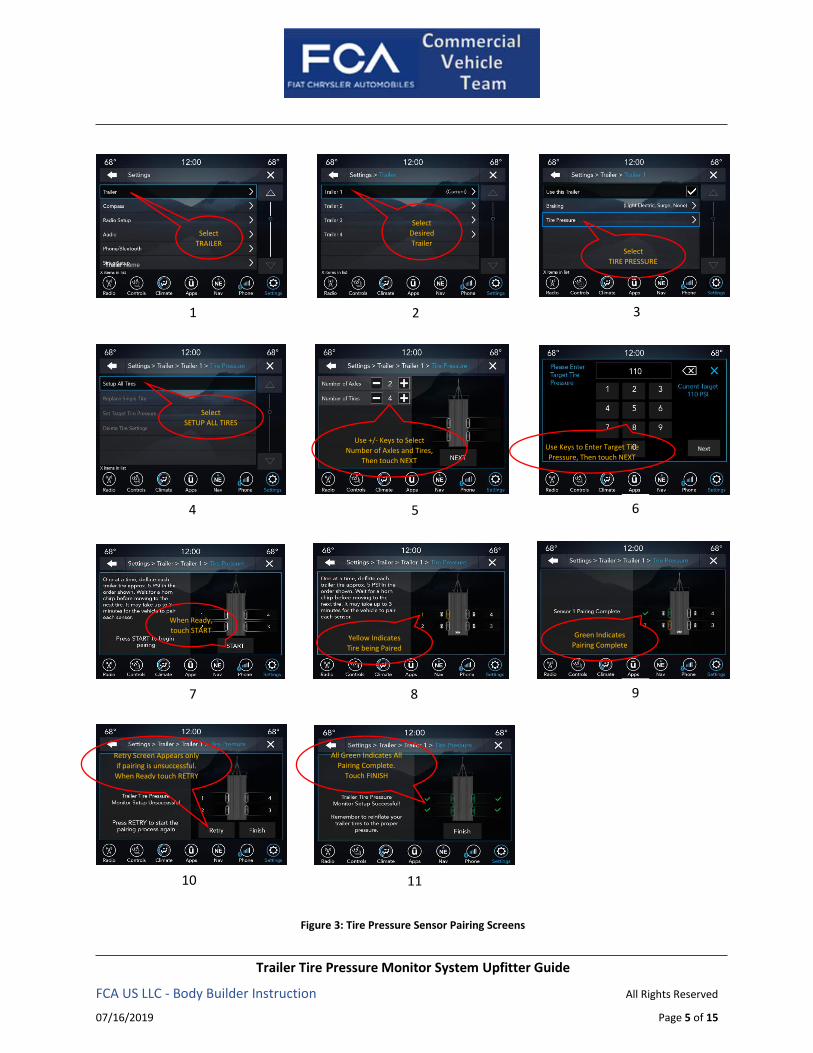
With the sensors installed and the trailer near or connected to your Ram truck, initiate the pairing process
by entering the SETTINGS menu then selecting TRAILER on the radio and following the screens outlined in
Figure 3 to set up trailer tire configuration, set the pressure threshold and pair the sensors. Please note that
although the screens may appear a bit different, the logic flow is the same for 8.4 inch and 12 inch displays.
The 8.4 inch display is shown. Setup and pairing should be done with the ignition in the RUN position and
the vehicle in PARK.
Tire sensors must be paired in order indicate on the radio screen. Starting with Tire 1, deflate tire by 5 PSI
(34 kPa) and wait for a horn chirp, indicating that the sensor has paired. It may take up to 3 minutes for the
chirp to occur. Repeat process on each tire, in order, until complete. Do not exit the pairing screen until
process is complete. If pairing was unsuccessful, a double horn chirp will sound, and a prompt on the
touchscreen will allow you to retry the procedure; “Retry” will only appear when setup fails. Each tire must
be successfully paired during a single pairing process to receive the success screen.
Trailer Tire Pressure Monitor System Upfitter Guide
FCA US LLC - Body Builder Instruction All Rights Reserved
07/16/2019 Page 5 of 15
Figure 3: Tire Pressure Sensor Pairing Screens
Trailer Name
Next
1 2 3
4 5 6
7 8 9
Select
TRAILER
Select
Desired
Trailer Select
TIRE PRESSURE
Select
SETUP ALL TIRES
Use +/- Keys to Select
Number of Axles and Tires,
Then touch NEXT
Use Keys to Enter Target Tire
Pressure, Then touch NEXT
When Ready,
touch START
11
Yellow Indicates
Tire being Paired
Green Indicates
Pairing Complete
All Green Indicates All
Pairing Complete.
Touch FINISH
10
Retry Screen Appears only
if pairing is unsuccessful.
When Ready touch RETRY
Trailer Tire Pressure Monitor System Upfitter Guide
FCA US LLC - Body Builder Instruction All Rights Reserved
07/16/2019 Page 6 of 15
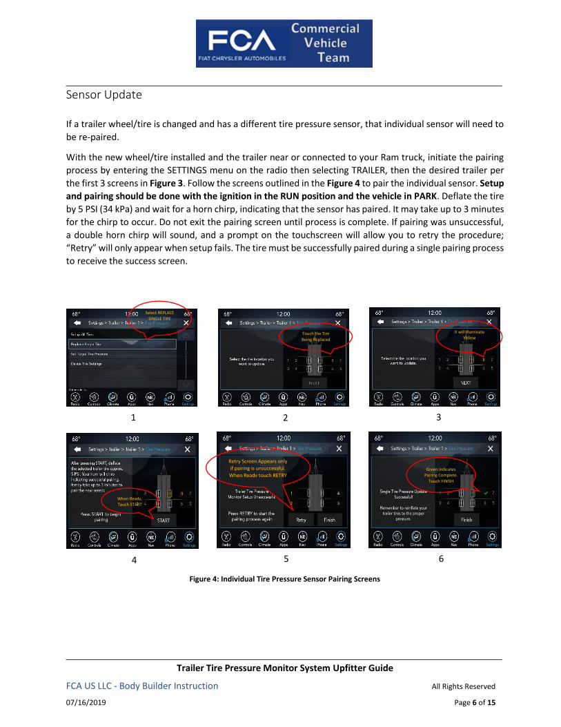
Sensor Update If a trailer wheel/tire is changed and has a different tire pressure sensor, that individual sensor will need to
be re-paired.
With the new wheel/tire installed and the trailer near or connected to your Ram truck, initiate the pairing
process by entering the SETTINGS menu on the radio then selecting TRAILER, then the desired trailer per
the first 3 screens in Figure 3. Follow the screens outlined in the Figure 4 to pair the individual sensor. Setup
and pairing should be done with the ignition in the RUN position and the vehicle in PARK. Deflate the tire
by 5 PSI (34 kPa) and wait for a horn chirp, indicating that the sensor has paired. It may take up to 3 minutes
for the chirp to occur. Do not exit the pairing screen until process is complete. If pairing was unsuccessful,
a double horn chirp will sound, and a prompt on the touchscreen will allow you to retry the procedure;
“Retry” will only appear when setup fails. The tire must be successfully paired during a single pairing process
to receive the success screen.
Figure 4: Individual Tire Pressure Sensor Pairing Screens
1 2 3
4 5
Select REPLACE
SINGLE TIRE
Touch the Tire
Being Replaced
It will Illuminate
Yellow
When Ready,
Touch START
Green Indicates
Pairing Complete.
Touch FINISH
6
Retry Screen Appears only
if pairing is unsuccessful.
When Ready touch RETRY
Trailer Tire Pressure Monitor System Upfitter Guide
FCA US LLC - Body Builder Instruction All Rights Reserved
07/16/2019 Page 7 of 15
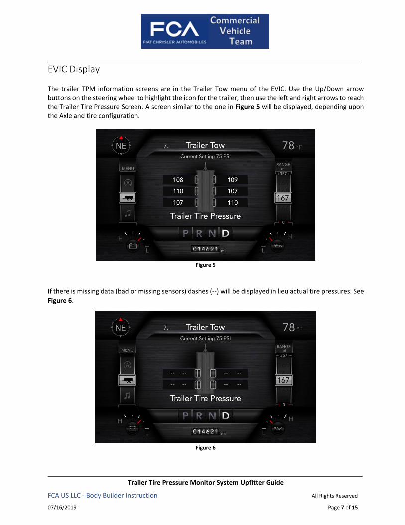
EVIC Display The trailer TPM information screens are in the Trailer Tow menu of the EVIC. Use the Up/Down arrow buttons on the steering wheel to highlight the icon for the trailer, then use the left and right arrows to reach the Trailer Tire Pressure Screen. A screen similar to the one in Figure 5 will be displayed, depending upon the Axle and tire configuration.
Figure 5
If there is missing data (bad or missing sensors) dashes (--) will be displayed in lieu actual tire pressures. See
Figure 6.
Figure 6
Trailer Tire Pressure Monitor System Upfitter Guide
FCA US LLC - Body Builder Instruction All Rights Reserved
07/16/2019 Page 8 of 15
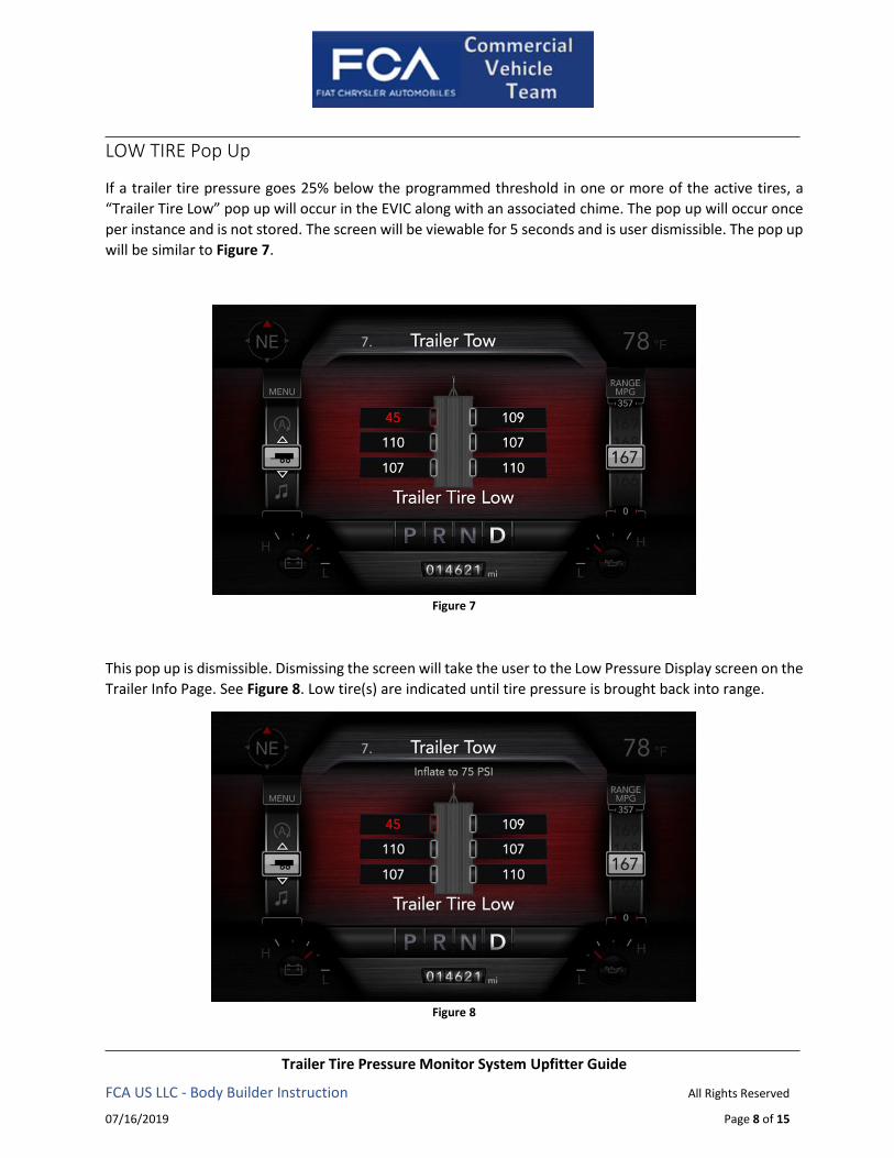
LOW TIRE Pop Up
If a trailer tire pressure goes 25% below the programmed threshold in one or more of the active tires, a
“Trailer Tire Low” pop up will occur in the EVIC along with an associated chime. The pop up will occur once
per instance and is not stored. The screen will be viewable for 5 seconds and is user dismissible. The pop up
will be similar to Figure 7.
Figure 7
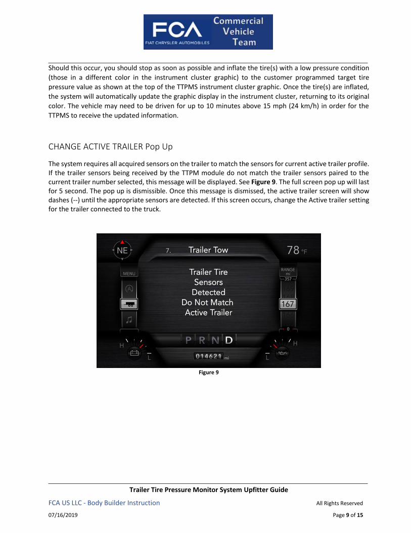
This pop up is dismissible. Dismissing the screen will take the user to the Low Pressure Display screen on the
Trailer Info Page. See Figure 8. Low tire(s) are indicated until tire pressure is brought back into range.
Figure 8
Trailer Tire Pressure Monitor System Upfitter Guide
FCA US LLC - Body Builder Instruction All Rights Reserved
07/16/2019 Page 9 of 15
Should this occur, you should stop as soon as possible and inflate the tire(s) with a low pressure condition
(those in a different color in the instrument cluster graphic) to the customer programmed target tire
pressure value as shown at the top of the TTPMS instrument cluster graphic. Once the tire(s) are inflated,
the system will automatically update the graphic display in the instrument cluster, returning to its original
color. The vehicle may need to be driven for up to 10 minutes above 15 mph (24 km/h) in order for the
TTPMS to receive the updated information.
CHANGE ACTIVE TRAILER Pop Up
The system requires all acquired sensors on the trailer to match the sensors for current active trailer profile. If the trailer sensors being received by the TTPM module do not match the trailer sensors paired to the current trailer number selected, this message will be displayed. See Figure 9. The full screen pop up will last for 5 second. The pop up is dismissible. Once this message is dismissed, the active trailer screen will show dashes (--) until the appropriate sensors are detected. If this screen occurs, change the Active trailer setting for the trailer connected to the truck.
Figure 9
Trailer Tire Pressure Monitor System Upfitter Guide
FCA US LLC - Body Builder Instruction All Rights Reserved
07/16/2019 Page 10 of 15
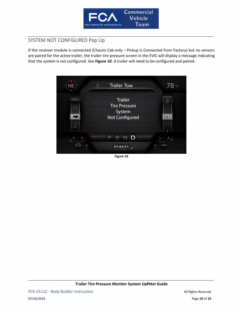
SYSTEM NOT CONFIGURED Pop Up
If the receiver module is connected (Chassis Cab only – Pickup is Connected from Factory) but no sensors
are paired for the active trailer, the trailer tire pressure screen in the EVIC will display a message indicating
that the system is not configured. See Figure 10. A trailer will need to be configured and paired.
Figure 10
Trailer Tire Pressure Monitor System Upfitter Guide
FCA US LLC - Body Builder Instruction All Rights Reserved
07/16/2019 Page 11 of 15
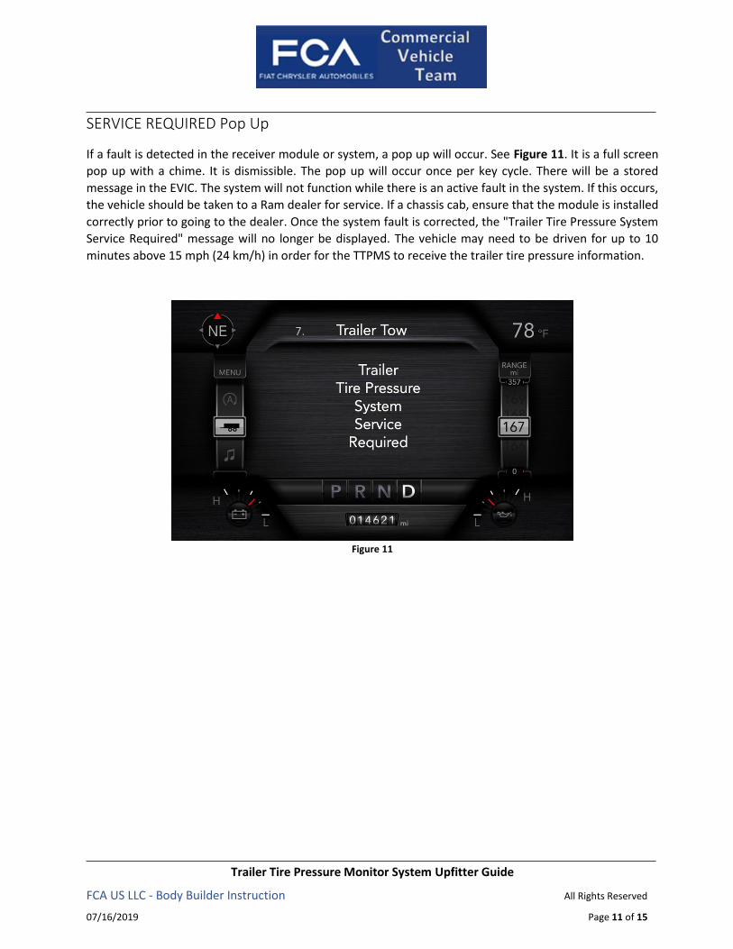
SERVICE REQUIRED Pop Up
If a fault is detected in the receiver module or system, a pop up will occur. See Figure 11. It is a full screen
pop up with a chime. It is dismissible. The pop up will occur once per key cycle. There will be a stored
message in the EVIC. The system will not function while there is an active fault in the system. If this occurs,
the vehicle should be taken to a Ram dealer for service. If a chassis cab, ensure that the module is installed
correctly prior to going to the dealer. Once the system fault is corrected, the "Trailer Tire Pressure System
Service Required" message will no longer be displayed. The vehicle may need to be driven for up to 10
minutes above 15 mph (24 km/h) in order for the TTPMS to receive the trailer tire pressure information.
Figure 11

Trailer Tire Pressure Monitor System Upfitter Guide
FCA US LLC - Body Builder Instruction All Rights Reserved
07/16/2019 Page 12 of 15
APPENDIX A
TPM SENSOR INSTALLATION
Installation Checklist
Carefully read and follow the installation instructions.
Inspect sensor for damage and/or visible defects. Do not use the sensor if it is damaged.
If sensor is damaged, you must use a new sensor and contact the OEM customer service.
For optimal function, the sensor may only be installed with original valves, accessories and
installation tools provided by the OEM.
Ensure sensors are only fitted to wheel rims meeting the requirements detailed in the rim
fitment guidelines section.
Ensure the correct nut torque is used for the relevant sensor kit. See front page for details.
Recommended Rim Fitment Guidelines
BEFORE INSTALLING THE TPM SENSOR, CHECK THE RIMS FOR ACCURACY OF FIT, TO ENSURE
COMPATABILITY FOR INSTALLATION:
A. The valve must not protrude beyond the outside edge of the rim.
B. The sensor housing must be in contact with the rim bed when the union nut is tightened.
C. The sensor housing must not protrude above the rim flange.
D. Wheel rim thickness at valve hole must be less than 6.0mm. NOTE: Grommet tool can also
be used to revert 5⁄8 inch kit back to 1⁄2 inch kit on TPMS.
Installation Warnings
For optimal function, installation should be performed by a trained technician only.
Maintenance and repair work should be performed by a trained technician only, and
according to the guidelines of the vehicle manufacturer.
Do not fit a damaged sensor to a wheel rim.
Do not fit the tire to the rim unless confident that the valve has been fitted correctly.
Do not re-use an old seal, or valve core if it has been removed from the valve stem. Always
ensure these components are replaced with new original equipment parts.
Do not re-use a nut, seat, or valve stem if they are damaged. Always ensure these
components are replaced with new original equipment parts.
Do not fit a sensor to unapproved wheel rims. All rims should be in accordance with TRA
standards.
If these installation instructions are not followed and this leads to a defect you may be
excluded from any warranty claim.
Trailer Tire Pressure Monitor System Upfitter Guide
FCA US LLC - Body Builder Instruction All Rights Reserved
07/16/2019 Page 13 of 15
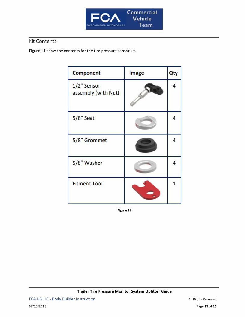
Kit Contents
Figure 11 show the contents for the tire pressure sensor kit.
Figure 11
Trailer Tire Pressure Monitor System Upfitter Guide
FCA US LLC - Body Builder Instruction All Rights Reserved
07/16/2019 Page 14 of 15
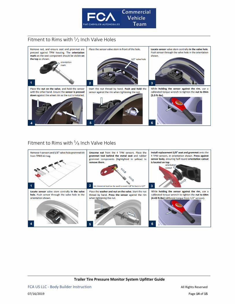
Fitment to Rims with 1⁄2 Inch Valve Holes
Fitment to Rims with 5⁄8 Inch Valve Holes

Trailer Tire Pressure Monitor System Upfitter Guide
FCA US LLC - Body Builder Instruction All Rights Reserved
07/16/2019 Page 15 of 15
Dismounting TPM Sensors
Dismounting Notes
For optimal function, dismounting of the tire and TPM sensor should be performed by a
trained technician only.
Ensure bead breaker and tire lever do not contact the sensor body, during tire removal. This
may cause damage to the TPM sensor. Do not re-fit a damaged sensor to a wheel rim.
Do not re-use an old seal, or valve core if it has been removed from the valve stem. Always
ensure these components are replaced with new original equipment parts.
Dismounting Sensors With 1⁄2 and 5⁄8 Inch Valve Holes