Embed Size (px)
DESCRIPTION
documental projeto
Citation preview

1
Beach Wheelchair Project
June 14, 2013
for Bridge II Sports
Team SandCrawler
Rory Aronson - [email protected]
Joshua Marcum - [email protected]
Sam Coyne - [email protected]
Alex Hayes - [email protected]
Alexa Colburn - [email protected]
Max Hessel - [email protected]
Benedikt Strauss - [email protected]
Marvin Rimmele - [email protected]
Marco Pietsch - [email protected]
College of Engineering
California Polytechnic State University, San Luis Obispo
Munich University of Applied Sciences
2013
2
Statement of Disclaimer Since this project is a result of a class assignment, it has been graded and accepted as
fulfillment of the course requirements. Acceptance does not imply technical accuracy or
reliability. Any use of information in this report is done at the risk of the user. These
risks may include catastrophic failure of the device or infringement of patent or copyright
laws. California Polytechnic State University at San Luis Obispo and its staff cannot be
held liable for any use or misuse of the project.
3
Table of Contents
Statement of Disclaimer
Table of Contents
Table of Figures
Table of Tables
1 - Executive Summary
2 - Introduction
Design Challenge
Background Research
Manual Beach Wheelchair Notes
Electric Beach Wheelchair Notes
Objectives
Customer Requirements
Optional Features
Design Development
Management Plan
Timetable
Gantt Chart
3 - Conceptual Models
Prototyping Lab
3 Wheeled Design
Using Bike Wheels
Using Hand Truck Wheels
Scissor Lift
Sliding Rear Assembly
Internal Gear Hub
Lever Drive
4 - Subsystem Pugh Matrices
Collapsing and Disassembling
Drive Systems
Number and Size of Wheels
Seat Adjustability
Seat Raising Mechanism
Gear Shifting
Tire Selection
Floating
Water Propulsion
5 - Initial Whole Concepts
Avila Wheelchair Designs
Joshua Marcum’s Initial Whole Concept
Sam Coyne’s Initial Whole Concept
Benedikt Strauss’s Initial Whole Concept
4
Alex Hayes’s Initial Whole Concept
Rory Aronson’s Initial Whole Concept
Marco Pietsch’s Initial Whole Concept
Marvin Rimmele’s Initial Whole Concept
Max Hessel’s Initial Whole Concept
Initial Whole Concept Matrix
6 - Iterated Whole Concepts
Rory Aronson’s Iterated Whole Concept
Marco Pietsch’s Iterated Whole Concept
Final Selection Process
7 - The Final Concept
Satisfying User Requirements
Safety Considerations
Gas Piston
Frame
Cranks
Belts
Hand Brake
Headrest and Footrests
Balloon Tires
8 - The Final Design
Frame
Construction
Wheels
Seat
Construction
Lower frame
Upper frame
Backrest Adjusting Mechanism
Torsion spring system
Linkages & bushing
Textile meshing
Safety
Calculations
Bolt Calculations
Linkages bushings calculation
Backrest adjusting mechanism - piston calculation
Piston
Hand Crank
Components
Construction
Rear Pulley
Construction
Gear Ratio Calculations
5
Brake
Construction
Maintenance
Cost Estimation
Testing Plan
Weight Capacity
Floatability
Speed and Ease of Maneuverability
Size
Disassembly
Piston Stability
Feedback from Potential Users
9 - Manufacturing
Overview
Main Frame Construction
Cutting Materials
Jigging
Finishing
Mini-frame Construction
Cutting Materials
Jigging
Finish Work
Push Handle Construction
Rear Drive Hub Construction
Cutting Materials
Machining Round 1
Welding
Machining Round 2
Tensioner Construction
Cutting Materials
Machining
Welding
Finishing
Pin Disk Construction
Crank Construction
Axle Construction
Rear Wheel Modification
Final Assembly
Seat Manufacturing
10 - Testing
Crank Realignment
Arm Maneuverability and Spacing
Component Size, Weight and Transportability
Ease of Assembly
6
Hand Force Requirements and Ramp Test
Drivability in Different Conditions
Floatation Stability
Safety
Braking
Maintenance
Engineering Specifications
Client Testing
11 - Implemented and Proposed Design Changes
Frame
Wheels
Belt Guard
Crank Assembly
Footrest Assembly
Drive System
Seat
Brake
Steerability
12 - Closing Remarks
13 - Appendices
Appendix 1: Existing Beach Wheelchair Designs
Appendix 2: Engineering Specifications List
Appendix 3: Gantt Chart
Appendix 4: Bill of Materials
Appendix 5: Detailed Drawings
Main Frame
Crank Assembly
Rear Hub Assembly
Front Wheel Assembly
Main Frame
Front Wheel Frames
Tensioner*
Pin Disk
Crank Arm
Drive Hub
Axle
Push Handles
Rear Drive Rod
Appendix 6: Supporting Analysis
Forces During Wheelchair and Hand cycle Use
Wheelchair Force Testing
Supporting Calculations for Load Analysis on Lower Member of Frame
Seat Module Calculations
Supporting Calculations for Force Loading Cases on Pin
7
Supporting Calculations for Forces on Crank arm
Supporting Calculations for Force on Crankshaft
Appendix 7: Team Contract
Team Sandspitter Contract
Member Roles and Responsibilities
Commitment and Accountability
Communication Pathways
Conflict Resolution
Project Room Civility
Appendix 8: Anodization Forms
Appendix 9: Instruction Manual
Parts List
1 - Seatbelt
Wheelchair Assembly
Seat Raising
Seat Lowering
Water Operations
Land Movement
8
Table of Figures Figure Number
Title Page
1.1 The Cal Poly Wheelchair 15
1.2 The Munich Wheelchair 15
2.1 The Natural Access Landeez™ manual beach wheelchair in Avila Beach
17
2.2 Electric beach wheelchair in Avila Beach 18
2.3 Method of approach in order of timeline, with iteration illustrated as backward lines
20
2.4 Project Gantt chart showing dependencies 22
3.1 Lego™ model 23
3.2 Floating Model 23
3.3 Wheel adjusting model 23
3.4 Tank tread model 23
3.5 Shock absorbing model 24
3.6 Hand crank model 24
3.7 The 3 wheeled conceptual model proved to be unstable 24
3.8 The 3 wheeled design with mountain bike tires proved to dig into the sand
25
3.9 Go-kart tires sinking into the sand 26
3.10 Modified go-kart tires to have an increased and flatter contact surface 26
3.11 Scissor lift conceptual model made of a wooden camping chair 27
3.12 Sliding rear assembly concept in the raised position 27
3.13 Sliding rear assembly concept in the lowered position 27
3.14 Internal gear hub conceptual model using bicycle parts 28
3.15 Internal gear hub conceptual model close up 28
3.16 Lever drive conceptual model 29
9
3.17 Close up on lever drive conceptual model 29
5.1 Joshua’s initial whole concept 43
5.2 Sam’s initial whole concept 44
5.3 Bene’s initial whole concept 45
5.4 Bene’s initial whole concept 45
5.5 Bene’s initial whole concept 45
5.6 Alex’s initial whole concept 46
5.7 Exploded view of Alex’s concept 47
5.8 Side profile of concept showing the raising and lowering aspects 47
5.9 Rory’s initial whole concept 49
5.10 Marco’s individual whole concept 50
5.11 Marvin’s initial whole concept 50
5.12 Max’s initial whole concept 51
6.1 Rory’s iterated whole concept 55
6.2 Marco’s iterated whole concept 56
7.1 Final concept design sketch 58
7.2 CAD render of the final concept design in the driving position 58
7.3 CAD render of the final concept design in the transfer position 59
7.4 CAD render of the final concept design in the floating and sand exit position
59
7.5 Gas piston sketches and rubber shielding 61
7.6 Piston lever system 62
7.7 Calculation of piston force based on geometry and user weight (Fy) 63
7.8 Detailed drawing of the frame. Member location and sizing subject to change
63
7.9 Close up sketch of the handle, ratchet, crank, and pulley assembly 64
7.10 Sketch of the toothed belt and drive gears 65
7.11 Hand brake mechanism showing the locked “parking brake” mode 65
10
7.12 Close up of the hand brake mechanism 66
7.13 49cm diameter balloon tire from Wheeleez.com 66
8.0 The SandCrawler 68
8.1 Final frame design. Made of square and cylindrical aluminum tubing 70
8.2 Actual footrest being bought 71
8.3 Close up conceptual CAD of footrests 71
8.4 Rear wheel with modifications to hub 72
8.5 Front wheel assembly 73
8.6 Lower frame cross section 74
8.7 Lower frame and the links for the upper frame 75
8.8 Backrest Adjustment Mechanism 76
8.9 Torsion Spring 77
8.10 Linkages & bushing in exploded view 78
8.11 Textile meshing wrapped around the circular tubes 79
8.12 Piston Assembly along with hydraulic line and push button 81
8.13 Exploded view of the hand crank 82
8.14 Free Body Diagram of shaft with Adjustable Lengths 83
8.15 Force and Moment Relations 83
8.16 Diagram illustrating the shear and bending forces on the pin 84
8.17 Bending and shear relations used 84
8.18 Relations used to determine bearing stress load on pin disk 85
8.19 Exploded view of the rear pulley assembly 87
8.20 Force testing at Avila Beach 88
8.21 Brake assembly 89
9.1 Cutting square tubing with the horizontal band saw 93
9.2 Cutting square tubing with the horizontal band saw 93
9.3 Mainframe halve jig 94
11
9.4 Second mainframe jig 94
9.5 Torsion spring resting on Frankenstein nubs for positioning and cutting length
94
9.6 Drilling the first holes in the frame using the mill 95
9.7 Miniframe Jig 1 96
9.8 Miniframe Jig 2 96
9.9 Caster mounting plate offset block 97
9.10 Prepared for welding push handle stock 98
9.11 Rear Drive Hub holes being machined with the rotary table 99
9.12 Rear Drive Hubs and a mill boring bar 99
9.13 Milling the circular grooves 100
9.14 Contact between the axle and plate 100
9.15 Final design of the brake/tensioner system 101
9.16 Pin Disk under construction with the drill press 101
9.17 Gates sprocket being mounted to pin disk. 101
9.18 Crank manufacturing in progress 102
9.19 Rear hub disassembled and ready to be drilled 103
9.20 The ‘merican way of squaring the seat 103
9.21 Perfect weld root 104
9.22 Tempering oven 105
9.23 Tungsten inert gas welding 105
10.1 The disassembled wheelchair in the back of a Subaru hatchback 107
10.2 Navigating the wheelchair ramp corner at Avila Beach 108
10.3 Sam operating the wheelchair on a 1:10 slope ramp 109
10.4 Operating the wheelchair on hard packed and wet sand 110
10.5 Operating the wheelchair in shallow water conditions 110
10.6 Operation in deep water conditions 111
12
10.7 Brake test at Avila 112
10.8 Rinsing off the wheelchair components with the beach shower 113
10.9 Robert approaching the sand at Avila 117
10.10 Robert in shallow water, enjoying himself 117
10.11 Robert and Cindy having fun on the beach. 118
10.12 Josh helping out Robert avoid some holes in the soft sand 118
10.13 Robert heading down the standard wheelchair ramp 119
10.14 Robert engaging the thumb screw on the cranks 119
11.1 Application of shaft collars on the crank assemblies 121
11.2 Spacer block on the mini frames to provide adequate clearance for the casters
122
11.3 Modified footrest posts 122
11.4 Gates belt drive misalignment 123
11.5 Application of shaft collars on the rear axle tube 123
11.6 Plastic sheet replacing the seat mesh material 124
11.7 Handles to fold the backrest down are difficult to use 125
11.8 Gate locking mechanism used as a parking brake 126
13
Table of Tables
Table Number
Description Page(s)
4.1 Collapsing and Disassembling Pugh Matrix for Folding Mechanism 31
4.2 Drive systems decision matrix for Belt Lever and Hand Crank Drive 32
4.3 Number and Size of Wheels Decision Matrix for 2 Big Wheels and 2
Small Front
33
4.4 Seat adjustability decision matrix final scores. 35
4.5 Seat raising mechanism Pugh matrix final scores 36
4.6 Drivetrain parameters and engineering targets 36
4.7 Drivetrain decision matrix results 37
4.8 Gear shifting subsystem matrix and final results. 37
4.9 Tire selection Pugh matrix results 38-39
4.1 Floating subsystem matrix and final results. 40
4.11 Water propulsion subsystem matrix and final results 41
5.1 Initial whole concept matrix criteria and weighting 52-53
5.2 Results of the matrix 54
7.1 Costs of balloon wheels from Wheeleez.com 67
8.1 Cost estimation 90
9.1 Estimated number of man hours for the manufacturing and assembly
of components
92
10.1 Weights of each component 108
10.2 Scale 1-10, higher scores mean easier operation 110
10.3 Engineering specifications results 113-116

14
15
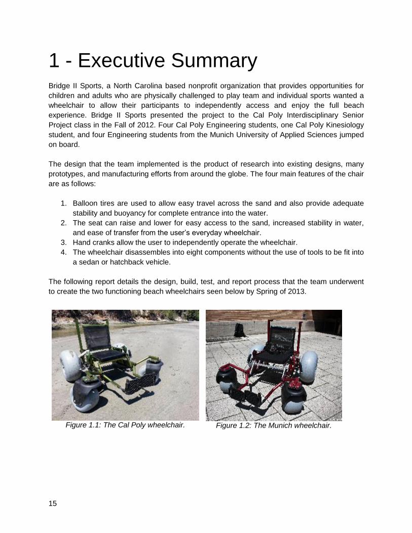
1 - Executive Summary
Bridge II Sports, a North Carolina based nonprofit organization that provides opportunities for
children and adults who are physically challenged to play team and individual sports wanted a
wheelchair to allow their participants to independently access and enjoy the full beach
experience. Bridge II Sports presented the project to the Cal Poly Interdisciplinary Senior
Project class in the Fall of 2012. Four Cal Poly Engineering students, one Cal Poly Kinesiology
student, and four Engineering students from the Munich University of Applied Sciences jumped
on board.
The design that the team implemented is the product of research into existing designs, many
prototypes, and manufacturing efforts from around the globe. The four main features of the chair
are as follows:
1. Balloon tires are used to allow easy travel across the sand and also provide adequate
stability and buoyancy for complete entrance into the water.
2. The seat can raise and lower for easy access to the sand, increased stability in water,
and ease of transfer from the user’s everyday wheelchair.
3. Hand cranks allow the user to independently operate the wheelchair.
4. The wheelchair disassembles into eight components without the use of tools to be fit into
a sedan or hatchback vehicle.
The following report details the design, build, test, and report process that the team underwent
to create the two functioning beach wheelchairs seen below by Spring of 2013.
Figure 1.1: The Cal Poly wheelchair.
Figure 1.2: The Munich wheelchair.
16
2 - Introduction
Design Challenge
Numerous beach wheelchairs exist today that provide people with disabilities the ability to
access the beach and enjoy oceans and lakes. This project’s goal is to design and build a new
beach wheelchair or device that will allow people with physical disabilities to move across a
sandy beach and go in the water with more ease and independence than before.
The client, Bridge II Sports of North Carolina, is an organization that enhances the lives of
people with physical disabilities through sport and physical activity. A group of four Cal Poly
Engineering students, a Cal Poly Kinesiology student, and four Munich University of Applied
Sciences Engineering students are designing this device for Bridge II Sports.
Currently there are a number of beach wheelchairs that exist but none that satisfy the needs of
the customer. For example, some wheelchairs do not allow the user to move independently,
while others are electric and do not provide the physical exercise desired by the customer.
Many wheelchairs do not allow the user to float in the water and very few beach wheelchairs are
collapsible enough to allow the user to independently put the wheelchair into their car.
The device’s design will take into consideration the user requirements set forth by the client as
well as features the design team has learned through research and testing of existing designs.
These requirements have been converted into an engineering specification list and are what will
be used to gauge the project’s success upon delivery to the sponsor. The main requirements
as presented by the customer are:
● Allow the user to experience the full beach experience
○ Allow the user to enter the water
○ Allow the user to reach the sand
○ Allow the user to move easily around the beach
● Provide exercise for the user
● Be transportable in the user’s car and require no assistance in loading
Background Research
The first stage of background research completed was finding and analyzing existing beach
wheelchair designs. We were able to contact John Lee and test out a manual and an electric
beach wheelchair in Avila Beach, California. Below are some important notes regarding each.
17
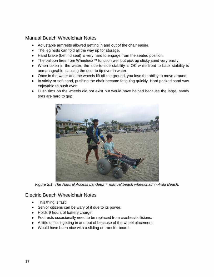
Manual Beach Wheelchair Notes
● Adjustable armrests allowed getting in and out of the chair easier.
● The leg rests can fold all the way up for storage.
● Hand brake (behind seat) is very hard to engage from the seated position.
● The balloon tires from Wheeleez™ function well but pick up sticky sand very easily.
● When taken in the water, the side-to-side stability is OK while front to back stability is
unmanageable, causing the user to tip over in water.
● Once in the water and the wheels lift off the ground, you lose the ability to move around.
● In sticky or soft sand, pushing the chair became fatiguing quickly. Hard packed sand was
enjoyable to push over.
● Push rims on the wheels did not exist but would have helped because the large, sandy
tires are hard to grip.
Figure 2.1: The Natural Access Landeez™ manual beach wheelchair in Avila Beach.
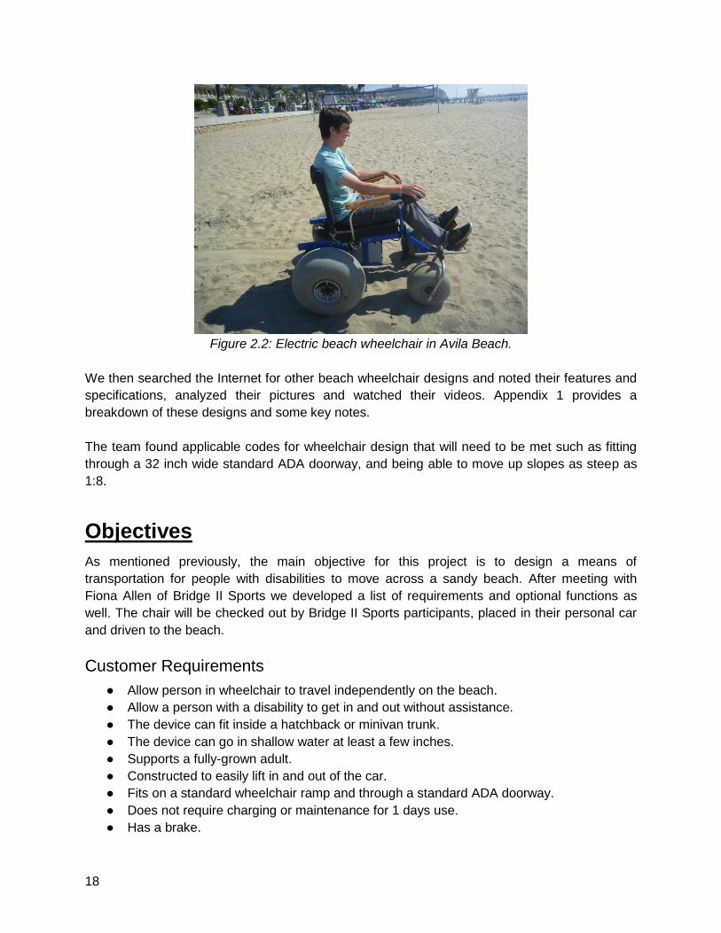
Electric Beach Wheelchair Notes
● This thing is fast!
● Senior citizens can be wary of it due to its power.
● Holds 9 hours of battery charge.
● Footrests occasionally need to be replaced from crashes/collisions.
● A little difficult getting in and out of because of the wheel placement.
● Would have been nice with a sliding or transfer board.
18
Figure 2.2: Electric beach wheelchair in Avila Beach.
We then searched the Internet for other beach wheelchair designs and noted their features and
specifications, analyzed their pictures and watched their videos. Appendix 1 provides a
breakdown of these designs and some key notes.
The team found applicable codes for wheelchair design that will need to be met such as fitting
through a 32 inch wide standard ADA doorway, and being able to move up slopes as steep as
1:8.
Objectives
As mentioned previously, the main objective for this project is to design a means of
transportation for people with disabilities to move across a sandy beach. After meeting with
Fiona Allen of Bridge II Sports we developed a list of requirements and optional functions as
well. The chair will be checked out by Bridge II Sports participants, placed in their personal car
and driven to the beach.
Customer Requirements
● Allow person in wheelchair to travel independently on the beach.
● Allow a person with a disability to get in and out without assistance.
● The device can fit inside a hatchback or minivan trunk.
● The device can go in shallow water at least a few inches.
● Supports a fully-grown adult.
● Constructed to easily lift in and out of the car.
● Fits on a standard wheelchair ramp and through a standard ADA doorway.
● Does not require charging or maintenance for 1 days use.
● Has a brake.
19
● Is adaptable for a wide variety of physical disabilities.
● Has leg and arm rests.
Optional Features
● Can fully float in the water.
● Accommodates accessories such as umbrellas or drink holders.
● Have power assistance or gear reductions.
● Have appropriate straps.
Most of the requirements that were generated for this project came from just a couple specific
ideas that the customer wanted and the rest of the requirements fell under them. The specific
needs that the customer asked for was that it had to give the experience of going to the beach
and had to let the user operate the device independently. Because these needs made a lot of
room for creativity, a lot of the requirements were made based off research. The requirements
that we found from our research was that it needed to have brakes, have adjustable leg and
armrests, be able to support an adult, and require little to no maintenance. Some of the
requirements that fall under letting the user have the ‘beach experience’ are in the optional
section with being able to float and ease of maneuverability. Because being an independent
person is so important to people with disabilities, the majority of the requirements fell under this
category. Requirements such as fitting into a hatchback or minivan and being lightweight
enough for someone with limited lifting abilities to move the device are a part of this category. A
few more requirements may be added or taken away from the design based on the early
communication with the clients. A list of all the current requirements that we plan on using is in
Appendix 2.
Design Development
Our team consists of 4 Cal Poly engineering students, a kinesiology student, and 4 Mechanical
engineering students from Munich, Germany. All of us are working together to create a finished
product. The beginning stages will start with identifying the problem. Researching and testing
existing products similar to what we want to design will also play a part in figuring out what
designs work, what do not, and what needs improving. The clients are contacted to figure out
user requirements. Once we have all the wants and needs of the user, a collaborative effort
between everyone in the team will make engineering specifications. Once we have some
specifications to work off of, a lot of brainstorming, sketches, and ideas for designs of the
wheelchair will be made. Different types of models will be made by all the team members and in
a few weeks the number of models will be narrowed down to the most ideal model. During this
time, research will be split up for different parts of the possible product so that it satisfies our
specifications.
By December 1, we will have our final conceptual design. While the Cal Poly division is off for
winter break, the Munich division will work on analysis and CAD models. Once the Cal Poly
division comes back from break, we take over where the Germans left off while they start on
20
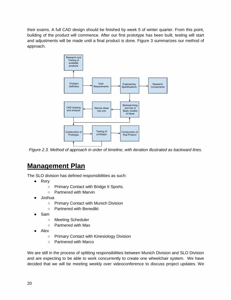
their exams. A full CAD design should be finished by week 5 of winter quarter. From this point,
building of the product will commence. After our first prototype has been built, testing will start
and adjustments will be made until a final product is done. Figure 3 summarizes our method of
approach.
Figure 2.3. Method of approach in order of timeline, with iteration illustrated as backward lines.
Management Plan
The SLO division has defined responsibilities as such:
● Rory
○ Primary Contact with Bridge II Sports.
○ Partnered with Marvin
● Joshua
○ Primary Contact with Munich Division
○ Partnered with Benedikt
● Sam
○ Meeting Scheduler
○ Partnered with Max
● Alex
○ Primary Contact with Kinesiology Division
○ Partnered with Marco
We are still in the process of splitting responsibilities between Munich Division and SLO Division
and are expecting to be able to work concurrently to create one wheelchair system. We have
decided that we will be meeting weekly over videoconference to discuss project updates. We
21
have also split into four sub teams consisting of 1 Cal Poly student and 1 Munich student so as
to streamline communication and increase collaboration.
The SLO Division will be meeting at a minimum of once per week on Thursday afternoons to
continue project progress. In addition, other meetings will be scheduled by the group as
necessary. Specific protocol has been created for group members who do not attend meetings
or participate actively in the project as seen in the Team Contract (Appendix 7). SLO Division,
through Rory will be contacting Bridge II Sports to provide updates and ask questions as often
as necessary, most likely once per two weeks.
SLO Division is estimating that we will each be spending roughly 7-10 hours per week for a total
of around 1000 hours spent on this project. In addition we expect that the Munich division will
be committing a similar amount of time for a total of 2000 man-hours for the whole project.
Timetable
● Requirements Document - 10/25/2012
● Conceptual Model - 10/30/2012
● Conceptual Design Report - 11/27/2012
● Project Schedule - 11/12/2012
● Detailed Design Document - 2/7/2012
● Delivery Date - 6/7/2013
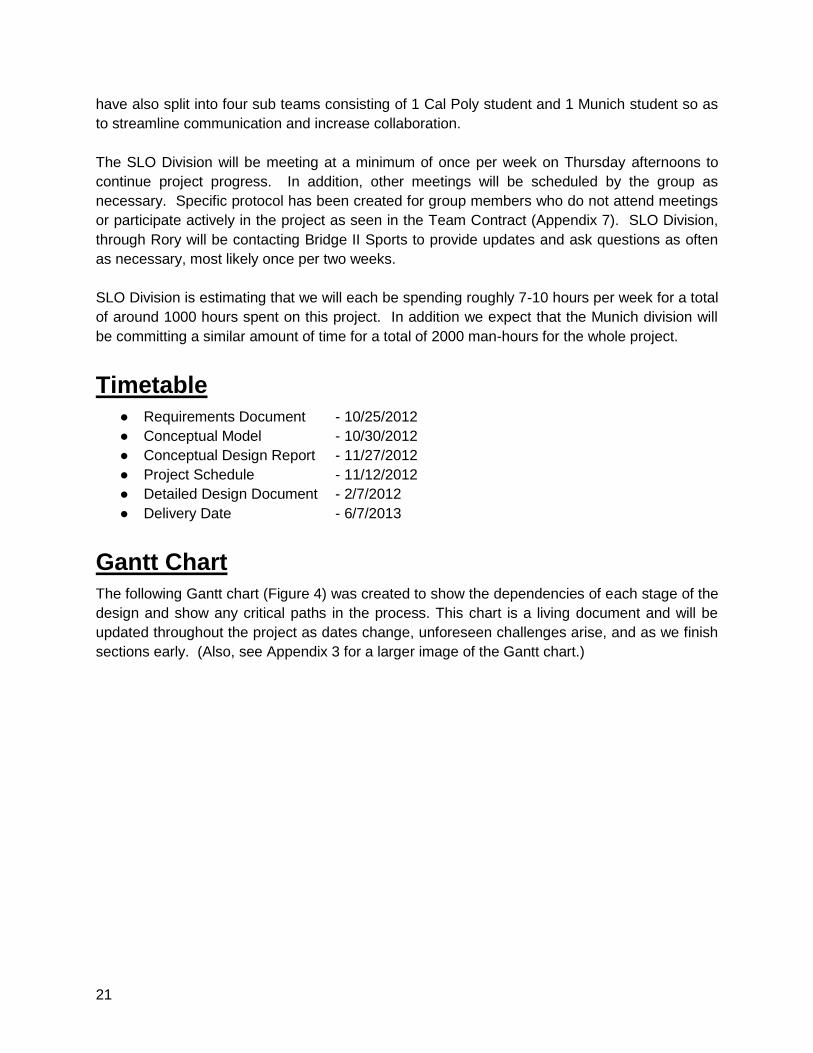
Gantt Chart
The following Gantt chart (Figure 4) was created to show the dependencies of each stage of the
design and show any critical paths in the process. This chart is a living document and will be
updated throughout the project as dates change, unforeseen challenges arise, and as we finish
sections early. (Also, see Appendix 3 for a larger image of the Gantt chart.)
22
Figure 2.4: Project Gantt chart showing dependencies.
23
3 - Conceptual Models
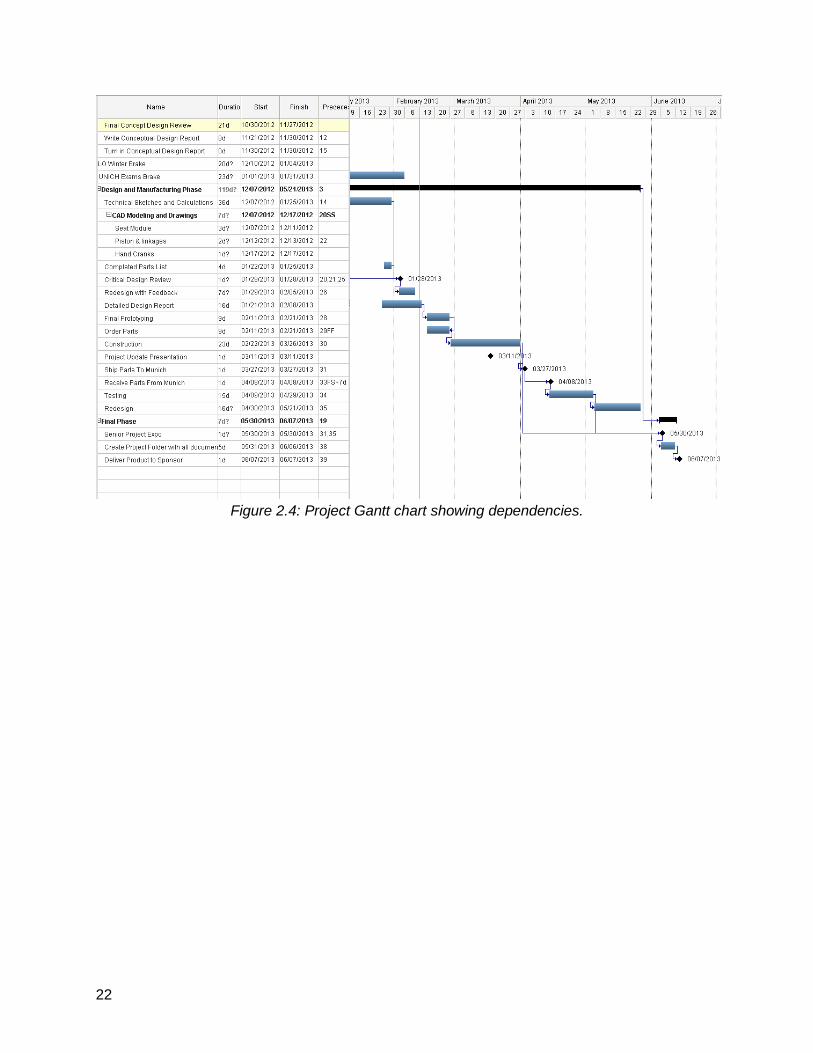
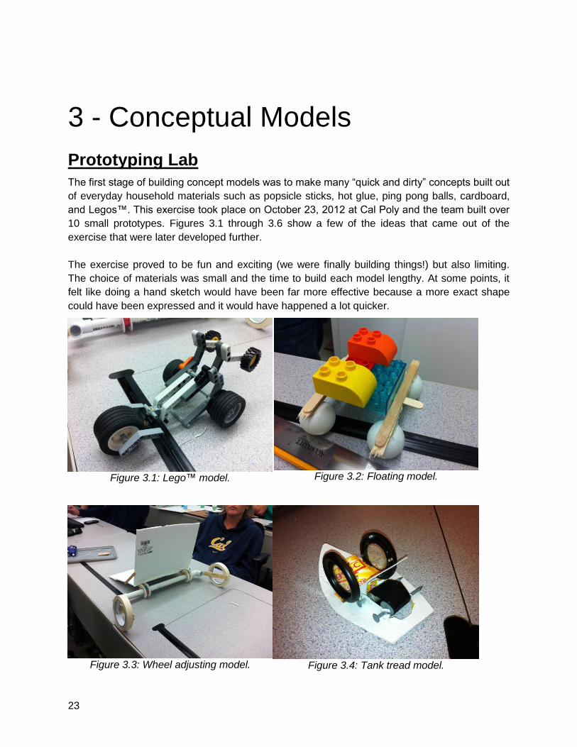
Prototyping Lab
The first stage of building concept models was to make many “quick and dirty” concepts built out
of everyday household materials such as popsicle sticks, hot glue, ping pong balls, cardboard,
and Legos™. This exercise took place on October 23, 2012 at Cal Poly and the team built over
10 small prototypes. Figures 3.1 through 3.6 show a few of the ideas that came out of the
exercise that were later developed further.
The exercise proved to be fun and exciting (we were finally building things!) but also limiting.
The choice of materials was small and the time to build each model lengthy. At some points, it
felt like doing a hand sketch would have been far more effective because a more exact shape
could have been expressed and it would have happened a lot quicker.
Figure 3.1: Lego™ model.
Figure 3.2: Floating model.
Figure 3.3: Wheel adjusting model.
Figure 3.4: Tank tread model.
24
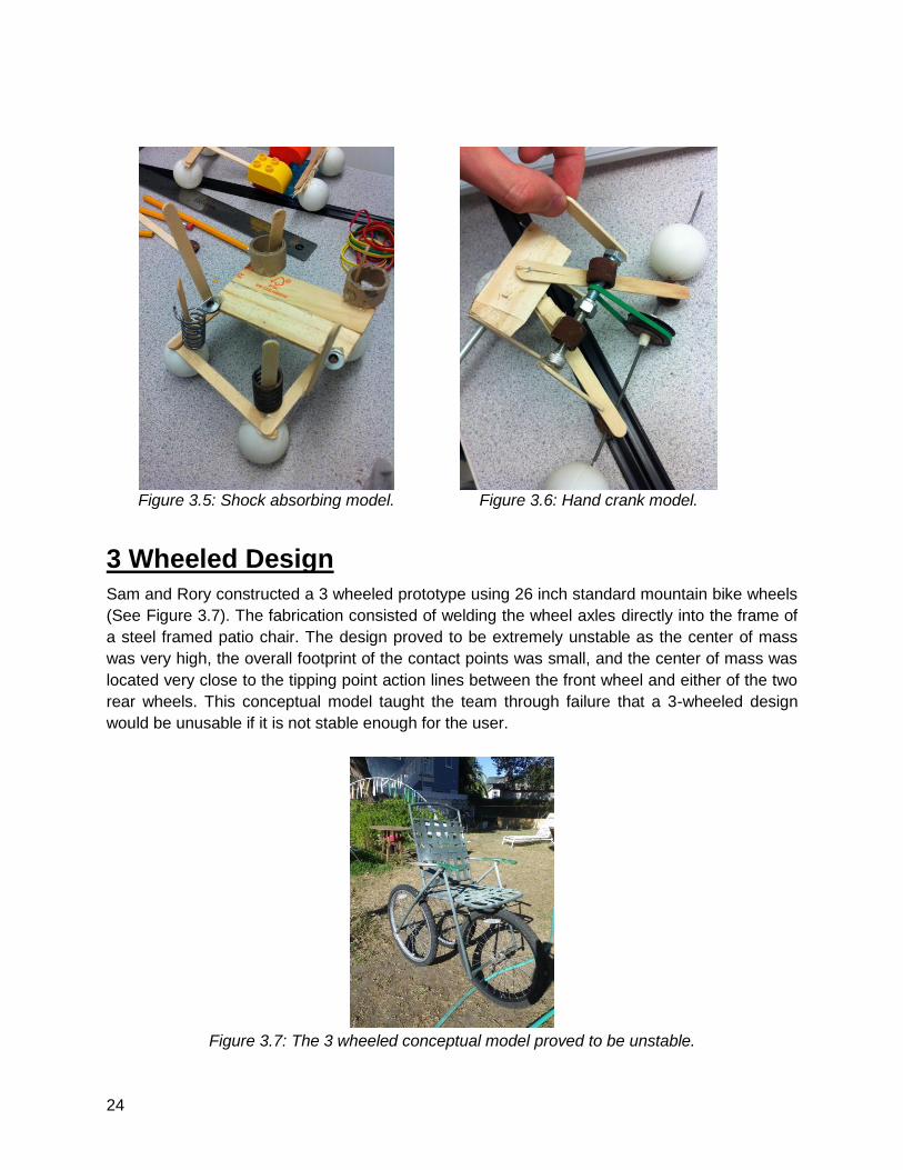
Figure 3.5: Shock absorbing model.
Figure 3.6: Hand crank model.
3 Wheeled Design
Sam and Rory constructed a 3 wheeled prototype using 26 inch standard mountain bike wheels
(See Figure 3.7). The fabrication consisted of welding the wheel axles directly into the frame of
a steel framed patio chair. The design proved to be extremely unstable as the center of mass
was very high, the overall footprint of the contact points was small, and the center of mass was
located very close to the tipping point action lines between the front wheel and either of the two
rear wheels. This conceptual model taught the team through failure that a 3-wheeled design
would be unusable if it is not stable enough for the user.
Figure 3.7: The 3 wheeled conceptual model proved to be unstable.
25
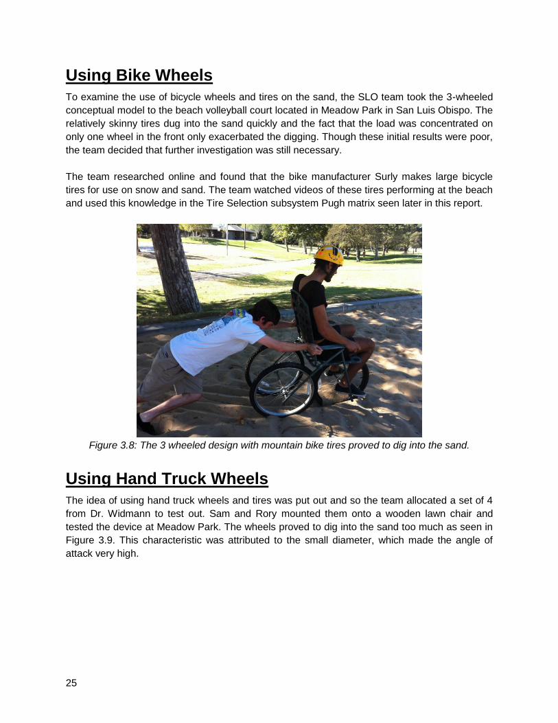
Using Bike Wheels
To examine the use of bicycle wheels and tires on the sand, the SLO team took the 3-wheeled
conceptual model to the beach volleyball court located in Meadow Park in San Luis Obispo. The
relatively skinny tires dug into the sand quickly and the fact that the load was concentrated on
only one wheel in the front only exacerbated the digging. Though these initial results were poor,
the team decided that further investigation was still necessary.
The team researched online and found that the bike manufacturer Surly makes large bicycle
tires for use on snow and sand. The team watched videos of these tires performing at the beach
and used this knowledge in the Tire Selection subsystem Pugh matrix seen later in this report.
Figure 3.8: The 3 wheeled design with mountain bike tires proved to dig into the sand.
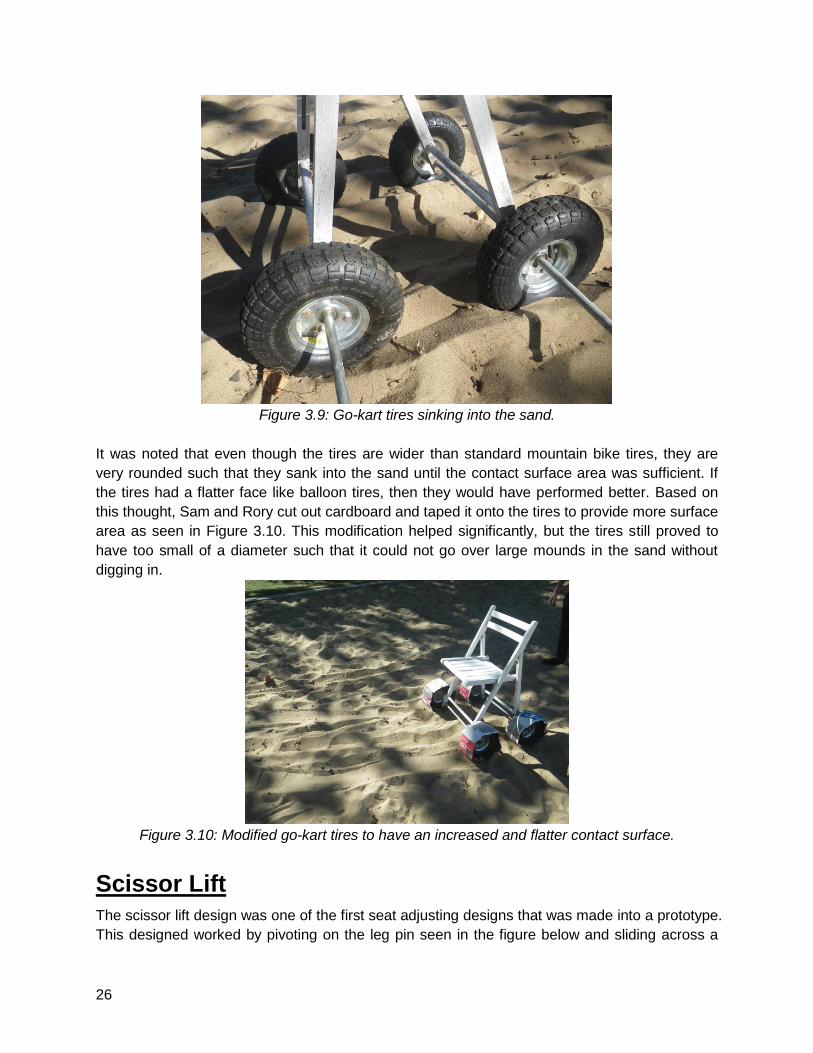
Using Hand Truck Wheels
The idea of using hand truck wheels and tires was put out and so the team allocated a set of 4
from Dr. Widmann to test out. Sam and Rory mounted them onto a wooden lawn chair and
tested the device at Meadow Park. The wheels proved to dig into the sand too much as seen in
Figure 3.9. This characteristic was attributed to the small diameter, which made the angle of
attack very high.
26
Figure 3.9: Go-kart tires sinking into the sand.
It was noted that even though the tires are wider than standard mountain bike tires, they are
very rounded such that they sank into the sand until the contact surface area was sufficient. If
the tires had a flatter face like balloon tires, then they would have performed better. Based on
this thought, Sam and Rory cut out cardboard and taped it onto the tires to provide more surface
area as seen in Figure 3.10. This modification helped significantly, but the tires still proved to
have too small of a diameter such that it could not go over large mounds in the sand without
digging in.
Figure 3.10: Modified go-kart tires to have an increased and flatter contact surface.
Scissor Lift
The scissor lift design was one of the first seat adjusting designs that was made into a prototype.
This designed worked by pivoting on the leg pin seen in the figure below and sliding across a
27
rod that is protruding out the front of the chair. Probably the biggest learning experience from
this design was that we found out that we needed a more complicated design in order for the
seat to lift back to the upright position.
Figure 3.11: Scissor lift conceptual model made of a wooden camping chair.
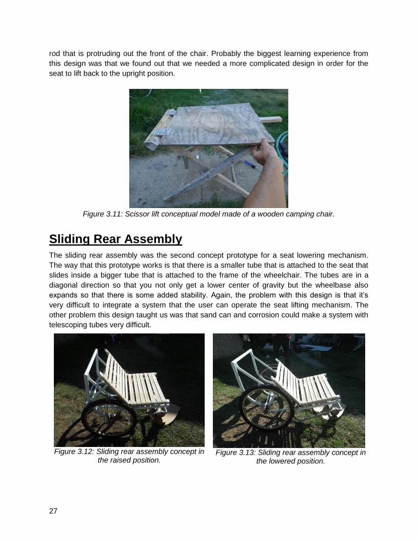
Sliding Rear Assembly
The sliding rear assembly was the second concept prototype for a seat lowering mechanism.
The way that this prototype works is that there is a smaller tube that is attached to the seat that
slides inside a bigger tube that is attached to the frame of the wheelchair. The tubes are in a
diagonal direction so that you not only get a lower center of gravity but the wheelbase also
expands so that there is some added stability. Again, the problem with this design is that it’s
very difficult to integrate a system that the user can operate the seat lifting mechanism. The
other problem this design taught us was that sand can and corrosion could make a system with
telescoping tubes very difficult.
Figure 3.12: Sliding rear assembly concept in
the raised position.
Figure 3.13: Sliding rear assembly concept in
the lowered position.
28
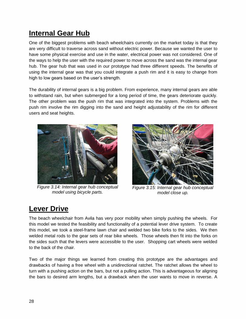
Internal Gear Hub
One of the biggest problems with beach wheelchairs currently on the market today is that they
are very difficult to traverse across sand without electric power. Because we wanted the user to
have some physical exercise and use in the water, electrical power was not considered. One of
the ways to help the user with the required power to move across the sand was the internal gear
hub. The gear hub that was used in our prototype had three different speeds. The benefits of
using the internal gear was that you could integrate a push rim and it is easy to change from
high to low gears based on the user’s strength.
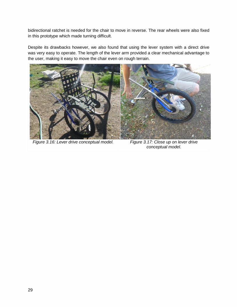
The durability of internal gears is a big problem. From experience, many internal gears are able
to withstand rain, but when submerged for a long period of time, the gears deteriorate quickly.
The other problem was the push rim that was integrated into the system. Problems with the
push rim involve the rim digging into the sand and height adjustability of the rim for different
users and seat heights.
Figure 3.14: Internal gear hub conceptual
model using bicycle parts.
Figure 3.15: Internal gear hub conceptual
model close up.
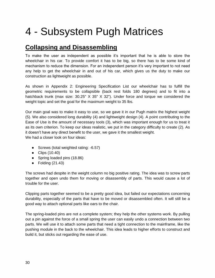
Lever Drive
The beach wheelchair from Avila has very poor mobility when simply pushing the wheels. For
this model we tested the feasibility and functionality of a potential lever drive system. To create
this model, we took a steel-frame lawn chair and welded two bike forks to the sides. We then
welded metal rods to the gear sets of rear bike wheels. Those wheels then fit into the forks on
the sides such that the levers were accessible to the user. Shopping cart wheels were welded
to the back of the chair.
Two of the major things we learned from creating this prototype are the advantages and
drawbacks of having a free wheel with a unidirectional ratchet. The ratchet allows the wheel to
turn with a pushing action on the bars, but not a pulling action. This is advantageous for aligning
the bars to desired arm lengths, but a drawback when the user wants to move in reverse. A
29
bidirectional ratchet is needed for the chair to move in reverse. The rear wheels were also fixed
in this prototype which made turning difficult.
Despite its drawbacks however, we also found that using the lever system with a direct drive
was very easy to operate. The length of the lever arm provided a clear mechanical advantage to
the user, making it easy to move the chair even on rough terrain.
Figure 3.16: Lever drive conceptual model.
Figure 3.17: Close up on lever drive
conceptual model.
30
4 - Subsystem Pugh Matrices
Collapsing and Disassembling
To make the user as independent as possible it’s important that he is able to store the
wheelchair in his car. To provide comfort it has to be big, so there has to be some kind of
mechanism to reduce the dimension. For an independent person it’s very important to not need
any help to get the wheelchair in and out of his car, which gives us the duty to make our
construction as lightweight as possible.
As shown in Appendix 2: Engineering Specification List our wheelchair has to fulfill the
geometric requirements to be collapsible (back rest folds 180 degrees) and to fit into a
hatchback trunk (max size: 30.25" X 35" X 32"). Under force and torque we considered the
weight topic and set the goal for the maximum weight to 35 lbs.
Our main goal was to make it easy to use, so we gave it in our Pugh matrix the highest weight
(5). We also considered long durability (4) and lightweight design (4). A point contributing to the
Ease of Use is the amount of necessary tools (3), which was important enough for us to treat it
as its own criterion. To keep our ideas realistic, we put in the category difficulty to create (2). As
it doesn’t have any direct benefit to the user, we gave it the smallest weight.
We had a closer look on four ideas:
● Screws (total weighted rating: -6.57)
● Clips (10.40)
● Spring loaded pins (18.86)
● Folding (21.43)
The screws had despite in the weight column no big positive rating. The idea was to screw parts
together and open undo them for moving or disassembly of parts. This would cause a lot of
trouble for the user.
Clipping parts together seemed to be a pretty good idea, but failed our expectations concerning
durability, especially of the parts that have to be moved or disassembled often. It will still be a
good way to attach optional parts like oars to the chair.
The spring-loaded pins are not a complete system; they help the other systems work. By pulling
out a pin against the force of a small spring the user can easily undo a connection between two
parts. We will use it to attach some parts that need a tight connection to the mainframe, like the
pushing module in the back to the wheelchair. This idea leads to higher efforts to construct and
build it, but sticks out regarding the ease of use.

31
Our favorite idea is the folding system; the exact rating is shown in Table 4.1. As easily seen it
performed excellent in the ease of use section. As it has no real weak points, it became our
clear favorite. It’s an easy technology which offers the user the highest possible comfort.
Wherever we want a part to be moved and not completely disassembled, which use a folding
system. When we want a part to be taken away from the frame out of weight reasons we will
use spring loaded pins. Those two concepts provide clearly the highest satisfaction for our users
and will fulfill our targets.
Table 4.1: Collapsing and Disassembling Pugh Matrix for Folding Mechanism.
Criteria Weight (1-5) Rory Alex Sam Joshua Marco Marvin Max Benedikt
Difficulty To Create 2 1 1 1 1 0 1 0 0
Ease of Use 5 2 2 2 2 2 2 1 1
Durability 4 1 0 0 1 1 0 0 0
Weight 4 2 1 2 1 1 1 1 1
Amount of necessary tools
3 2 0 2 1 0 0 1 1
Total - 30 16 26 23 18 16 12 9
AVG Total 21.43
Drive Systems
As can be seen in the green column, the ratcheting lever design has the most positive attributes
and least negative attributes compared to all the other columns. However, the Toothed Belt
Drive system excels in some important areas that the Ratcheting Lever design does not, namely
the water and sand endurance criterion. If the ratcheting system were made out of metal, the
sand would increase wear on the parts, and seawater could corrode it. Small intricate parts that
could be hard to replace would wear the fastest. Whereas the Toothed Belt drive could be used
in the water and sand without corroding or having major wear damage.
If the pulleys that will receive the belt are made of plastic also, then the parts will easily function
in sand and water with little issue. The plastic chain can be considered for the same reasons as
the belt, however it would be a little more complicated to assemble, and more expensive to build.
The major advantage to the ratcheting lever over the toothed belt is the ease of assembly.
The belt might be difficult to put on to the pulley under tension, whereas the ratcheting gears will
be attached to the wheel directly and the only other part to assemble would be the pawl, which
fits on a pin. Furthermore there may be a need for some lubricants for the pulley bearings,
whereas the ratchet pawl needs only to be strong enough to withstand constant cyclic loading
without much wear.
32
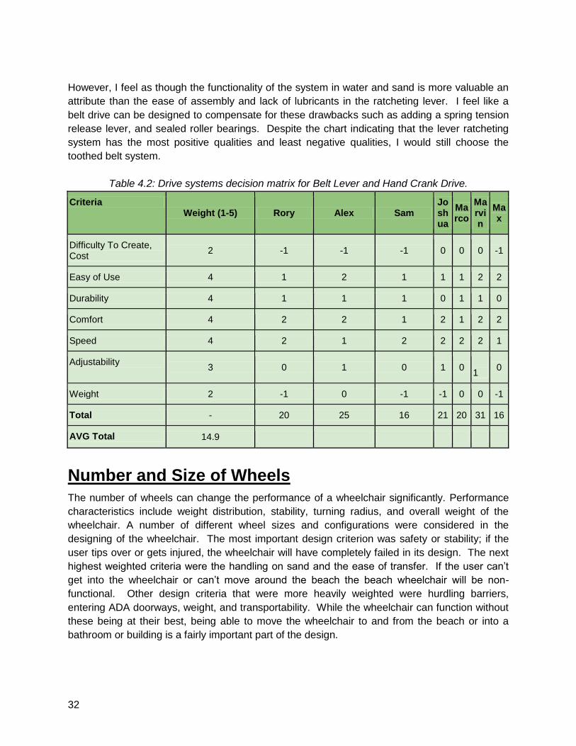
However, I feel as though the functionality of the system in water and sand is more valuable an
attribute than the ease of assembly and lack of lubricants in the ratcheting lever. I feel like a
belt drive can be designed to compensate for these drawbacks such as adding a spring tension
release lever, and sealed roller bearings. Despite the chart indicating that the lever ratcheting
system has the most positive qualities and least negative qualities, I would still choose the
toothed belt system.
Table 4.2: Drive systems decision matrix for Belt Lever and Hand Crank Drive.
Criteria Weight (1-5) Rory Alex Sam
Joshua
Marco
Marvin
Max
Difficulty To Create, Cost
2 -1 -1 -1 0 0 0 -1
Easy of Use 4 1 2 1 1 1 2 2
Durability 4 1 1 1 0 1 1 0
Comfort 4 2 2 1 2 1 2 2
Speed 4 2 1 2 2 2 2 1
Adjustability 3 0 1 0 1 0
1
0
Weight 2 -1 0 -1 -1 0 0 -1
Total - 20 25 16 21 20 31 16
AVG Total 14.9
Number and Size of Wheels
The number of wheels can change the performance of a wheelchair significantly. Performance
characteristics include weight distribution, stability, turning radius, and overall weight of the
wheelchair. A number of different wheel sizes and configurations were considered in the
designing of the wheelchair. The most important design criterion was safety or stability; if the
user tips over or gets injured, the wheelchair will have completely failed in its design. The next
highest weighted criteria were the handling on sand and the ease of transfer. If the user can’t
get into the wheelchair or can’t move around the beach the beach wheelchair will be non-
functional. Other design criteria that were more heavily weighted were hurdling barriers,
entering ADA doorways, weight, and transportability. While the wheelchair can function without
these being at their best, being able to move the wheelchair to and from the beach or into a
bathroom or building is a fairly important part of the design.
33
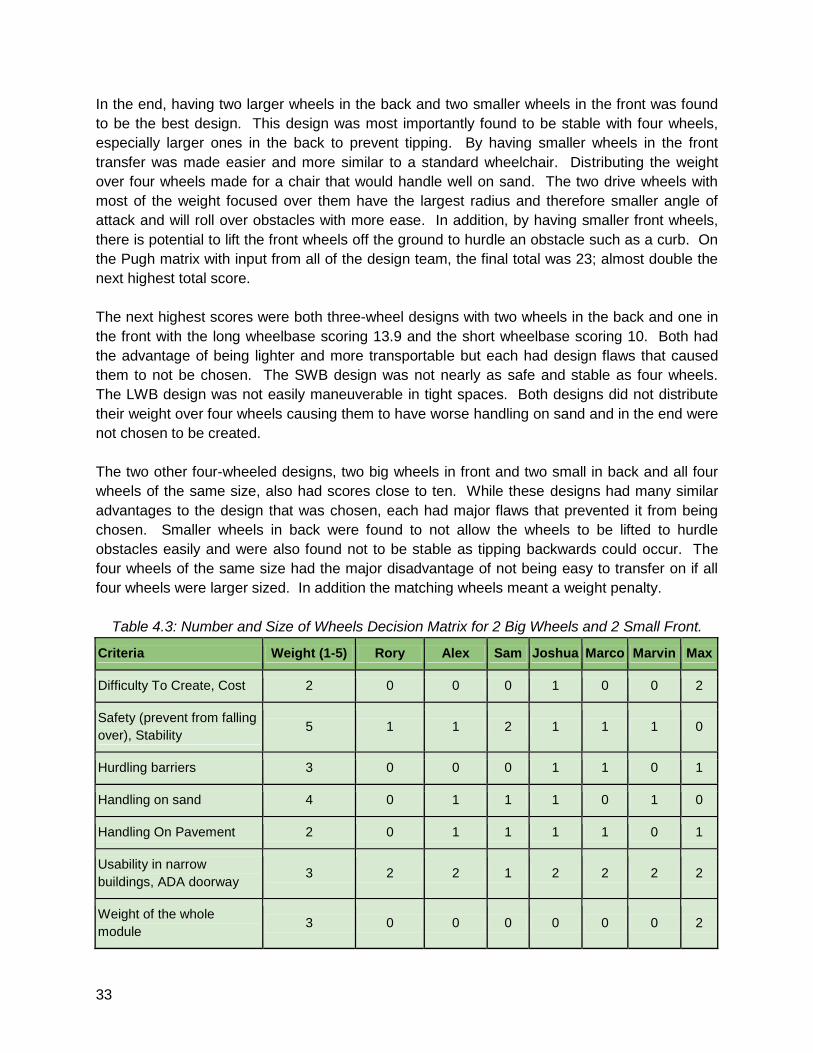
In the end, having two larger wheels in the back and two smaller wheels in the front was found
to be the best design. This design was most importantly found to be stable with four wheels,
especially larger ones in the back to prevent tipping. By having smaller wheels in the front
transfer was made easier and more similar to a standard wheelchair. Distributing the weight
over four wheels made for a chair that would handle well on sand. The two drive wheels with
most of the weight focused over them have the largest radius and therefore smaller angle of
attack and will roll over obstacles with more ease. In addition, by having smaller front wheels,
there is potential to lift the front wheels off the ground to hurdle an obstacle such as a curb. On
the Pugh matrix with input from all of the design team, the final total was 23; almost double the
next highest total score.
The next highest scores were both three-wheel designs with two wheels in the back and one in
the front with the long wheelbase scoring 13.9 and the short wheelbase scoring 10. Both had
the advantage of being lighter and more transportable but each had design flaws that caused
them to not be chosen. The SWB design was not nearly as safe and stable as four wheels.
The LWB design was not easily maneuverable in tight spaces. Both designs did not distribute
their weight over four wheels causing them to have worse handling on sand and in the end were
not chosen to be created.
The two other four-wheeled designs, two big wheels in front and two small in back and all four
wheels of the same size, also had scores close to ten. While these designs had many similar
advantages to the design that was chosen, each had major flaws that prevented it from being
chosen. Smaller wheels in back were found to not allow the wheels to be lifted to hurdle
obstacles easily and were also found not to be stable as tipping backwards could occur. The
four wheels of the same size had the major disadvantage of not being easy to transfer on if all
four wheels were larger sized. In addition the matching wheels meant a weight penalty.
Table 4.3: Number and Size of Wheels Decision Matrix for 2 Big Wheels and 2 Small Front.
Criteria Weight (1-5) Rory Alex Sam Joshua Marco Marvin Max
Difficulty To Create, Cost 2 0 0 0 1 0 0 2
Safety (prevent from falling
over), Stability 5 1 1 2 1 1 1 0
Hurdling barriers 3 0 0 0 1 1 0 1
Handling on sand 4 0 1 1 1 0 1 0
Handling On Pavement 2 0 1 1 1 1 0 1
Usability in narrow
buildings, ADA doorway 3 2 2 1 2 2 2 2
Weight of the whole
module 3 0 0 0 0 0 0 2
34
Ease of transfer 4 2 1 1 1 1 1 1
Transportability 3 0 0 0 1 1 0 1
Sexiness/Style 1 -1 0 1 0 0 0 -1
Total - 18 21 24 29 23 19 27
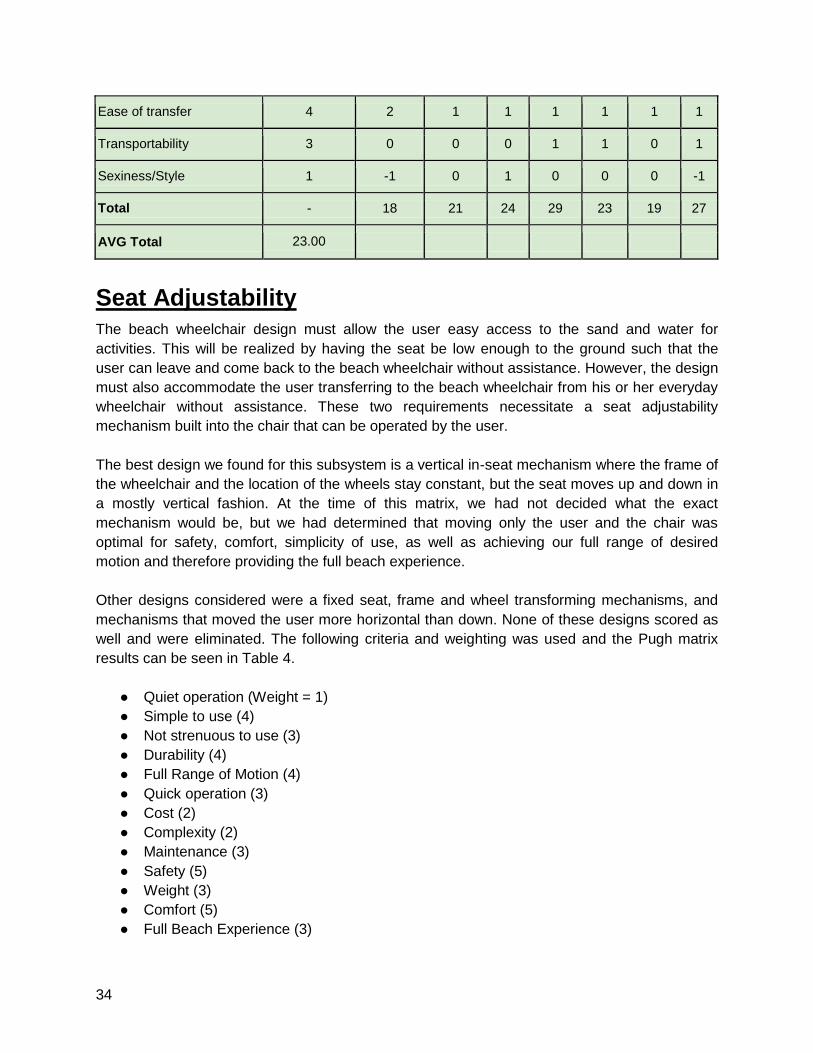
AVG Total 23.00
Seat Adjustability
The beach wheelchair design must allow the user easy access to the sand and water for
activities. This will be realized by having the seat be low enough to the ground such that the
user can leave and come back to the beach wheelchair without assistance. However, the design
must also accommodate the user transferring to the beach wheelchair from his or her everyday
wheelchair without assistance. These two requirements necessitate a seat adjustability
mechanism built into the chair that can be operated by the user.
The best design we found for this subsystem is a vertical in-seat mechanism where the frame of
the wheelchair and the location of the wheels stay constant, but the seat moves up and down in
a mostly vertical fashion. At the time of this matrix, we had not decided what the exact
mechanism would be, but we had determined that moving only the user and the chair was
optimal for safety, comfort, simplicity of use, as well as achieving our full range of desired
motion and therefore providing the full beach experience.
Other designs considered were a fixed seat, frame and wheel transforming mechanisms, and
mechanisms that moved the user more horizontal than down. None of these designs scored as
well and were eliminated. The following criteria and weighting was used and the Pugh matrix
results can be seen in Table 4.
● Quiet operation (Weight = 1)
● Simple to use (4)
● Not strenuous to use (3)
● Durability (4)
● Full Range of Motion (4)
● Quick operation (3)
● Cost (2)
● Complexity (2)
● Maintenance (3)
● Safety (5)
● Weight (3)
● Comfort (5)
● Full Beach Experience (3)
35
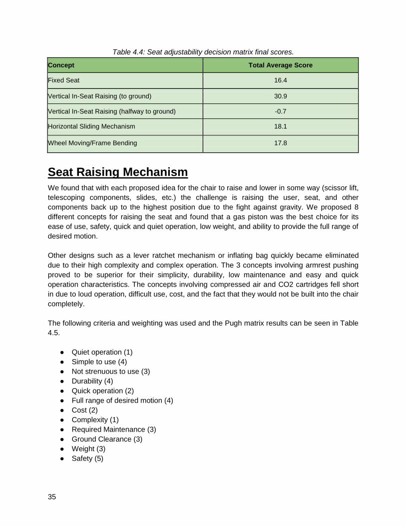
Table 4.4: Seat adjustability decision matrix final scores.
Concept Total Average Score
Fixed Seat 16.4
Vertical In-Seat Raising (to ground) 30.9
Vertical In-Seat Raising (halfway to ground) -0.7
Horizontal Sliding Mechanism 18.1
Wheel Moving/Frame Bending 17.8
Seat Raising Mechanism
We found that with each proposed idea for the chair to raise and lower in some way (scissor lift,
telescoping components, slides, etc.) the challenge is raising the user, seat, and other
components back up to the highest position due to the fight against gravity. We proposed 8
different concepts for raising the seat and found that a gas piston was the best choice for its
ease of use, safety, quick and quiet operation, low weight, and ability to provide the full range of
desired motion.
Other designs such as a lever ratchet mechanism or inflating bag quickly became eliminated
due to their high complexity and complex operation. The 3 concepts involving armrest pushing
proved to be superior for their simplicity, durability, low maintenance and easy and quick
operation characteristics. The concepts involving compressed air and CO2 cartridges fell short
in due to loud operation, difficult use, cost, and the fact that they would not be built into the chair
completely.
The following criteria and weighting was used and the Pugh matrix results can be seen in Table
4.5.
● Quiet operation (1)
● Simple to use (4)
● Not strenuous to use (3)
● Durability (4)
● Quick operation (2)
● Full range of desired motion (4)
● Cost (2)
● Complexity (1)
● Required Maintenance (3)
● Ground Clearance (3)
● Weight (3)
● Safety (5)
36
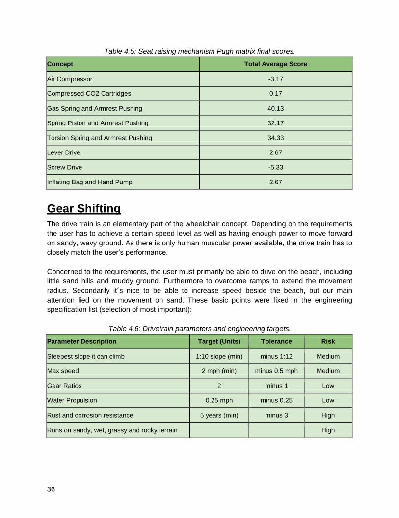
Table 4.5: Seat raising mechanism Pugh matrix final scores.
Concept Total Average Score
Air Compressor -3.17
Compressed CO2 Cartridges 0.17
Gas Spring and Armrest Pushing 40.13
Spring Piston and Armrest Pushing 32.17
Torsion Spring and Armrest Pushing 34.33
Lever Drive 2.67
Screw Drive -5.33
Inflating Bag and Hand Pump 2.67
Gear Shifting
The drive train is an elementary part of the wheelchair concept. Depending on the requirements
the user has to achieve a certain speed level as well as having enough power to move forward
on sandy, wavy ground. As there is only human muscular power available, the drive train has to
closely match the user’s performance.
Concerned to the requirements, the user must primarily be able to drive on the beach, including
little sand hills and muddy ground. Furthermore to overcome ramps to extend the movement
radius. Secondarily it´s nice to be able to increase speed beside the beach, but our main
attention lied on the movement on sand. These basic points were fixed in the engineering
specification list (selection of most important):
Table 4.6: Drivetrain parameters and engineering targets.
Parameter Description Target (Units) Tolerance Risk
Steepest slope it can climb 1:10 slope (min) minus 1:12 Medium
Max speed 2 mph (min) minus 0.5 mph Medium
Gear Ratios 2 minus 1 Low
Water Propulsion 0.25 mph minus 0.25 Low
Rust and corrosion resistance 5 years (min) minus 3 High
Runs on sandy, wet, grassy and rocky terrain High
37
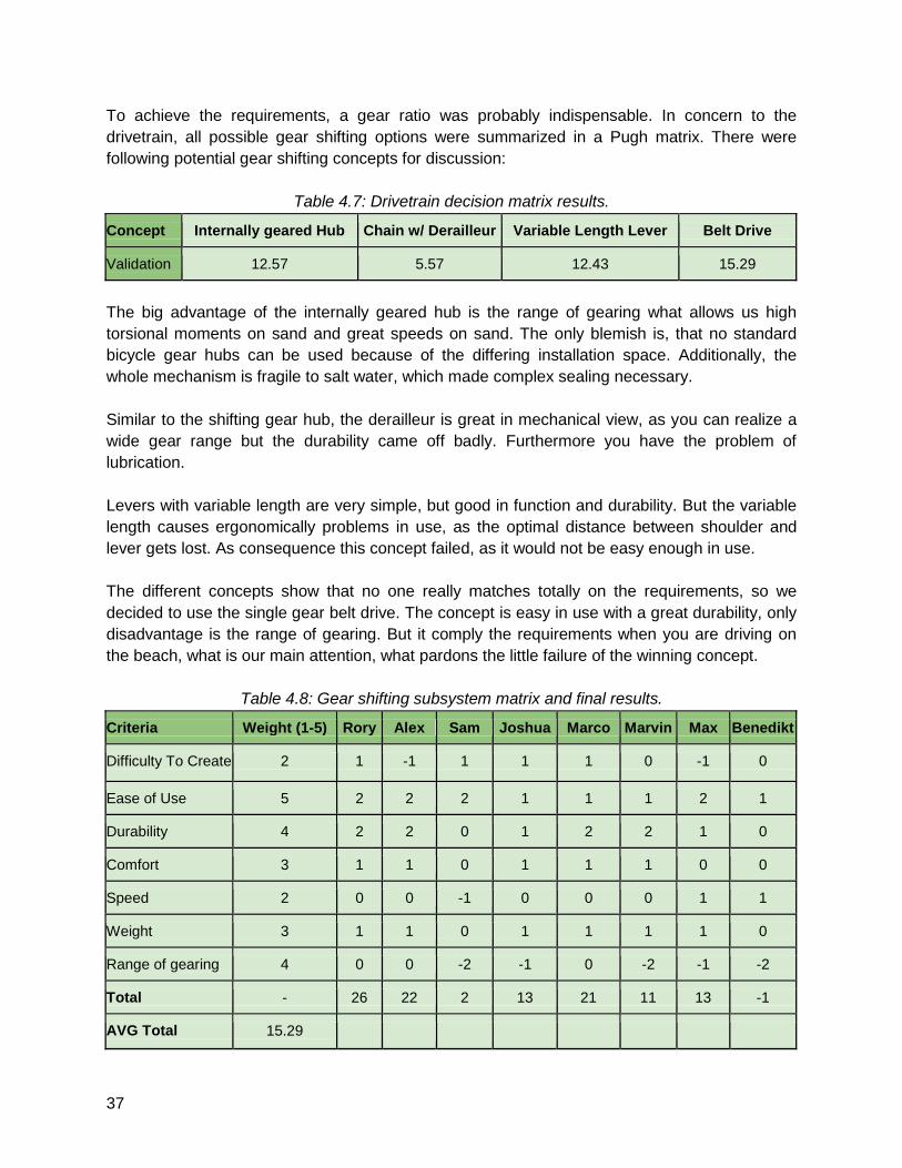
To achieve the requirements, a gear ratio was probably indispensable. In concern to the
drivetrain, all possible gear shifting options were summarized in a Pugh matrix. There were
following potential gear shifting concepts for discussion:
Table 4.7: Drivetrain decision matrix results.
Concept Internally geared Hub Chain w/ Derailleur Variable Length Lever Belt Drive
Validation 12.57 5.57 12.43 15.29
The big advantage of the internally geared hub is the range of gearing what allows us high
torsional moments on sand and great speeds on sand. The only blemish is, that no standard
bicycle gear hubs can be used because of the differing installation space. Additionally, the
whole mechanism is fragile to salt water, which made complex sealing necessary.
Similar to the shifting gear hub, the derailleur is great in mechanical view, as you can realize a
wide gear range but the durability came off badly. Furthermore you have the problem of
lubrication.
Levers with variable length are very simple, but good in function and durability. But the variable
length causes ergonomically problems in use, as the optimal distance between shoulder and
lever gets lost. As consequence this concept failed, as it would not be easy enough in use.
The different concepts show that no one really matches totally on the requirements, so we
decided to use the single gear belt drive. The concept is easy in use with a great durability, only
disadvantage is the range of gearing. But it comply the requirements when you are driving on
the beach, what is our main attention, what pardons the little failure of the winning concept.
Table 4.8: Gear shifting subsystem matrix and final results.
Criteria Weight (1-5) Rory Alex Sam Joshua Marco Marvin Max Benedikt
Difficulty To Create 2 1 -1 1 1 1 0 -1 0
Ease of Use 5 2 2 2 1 1 1 2 1
Durability 4 2 2 0 1 2 2 1 0
Comfort 3 1 1 0 1 1 1 0 0
Speed 2 0 0 -1 0 0 0 1 1
Weight 3 1 1 0 1 1 1 1 0
Range of gearing 4 0 0 -2 -1 0 -2 -1 -2
Total - 26 22 2 13 21 11 13 -1
AVG Total 15.29
38
Tire Selection
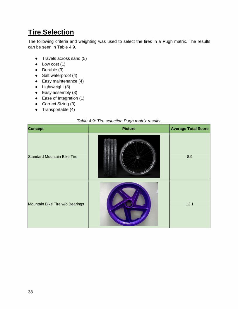
The following criteria and weighting was used to select the tires in a Pugh matrix. The results
can be seen in Table 4.9.
● Travels across sand (5)
● Low cost (1)
● Durable (3)
● Salt waterproof (4)
● Easy maintenance (4)
● Lightweight (3)
● Easy assembly (3)
● Ease of Integration (1)
● Correct Sizing (3)
● Transportable (4)
Table 4.9: Tire selection Pugh matrix results.
Concept Picture Average Total Score
Standard Mountain Bike Tire
8.9
Mountain Bike Tire w/o Bearings
12.1
39
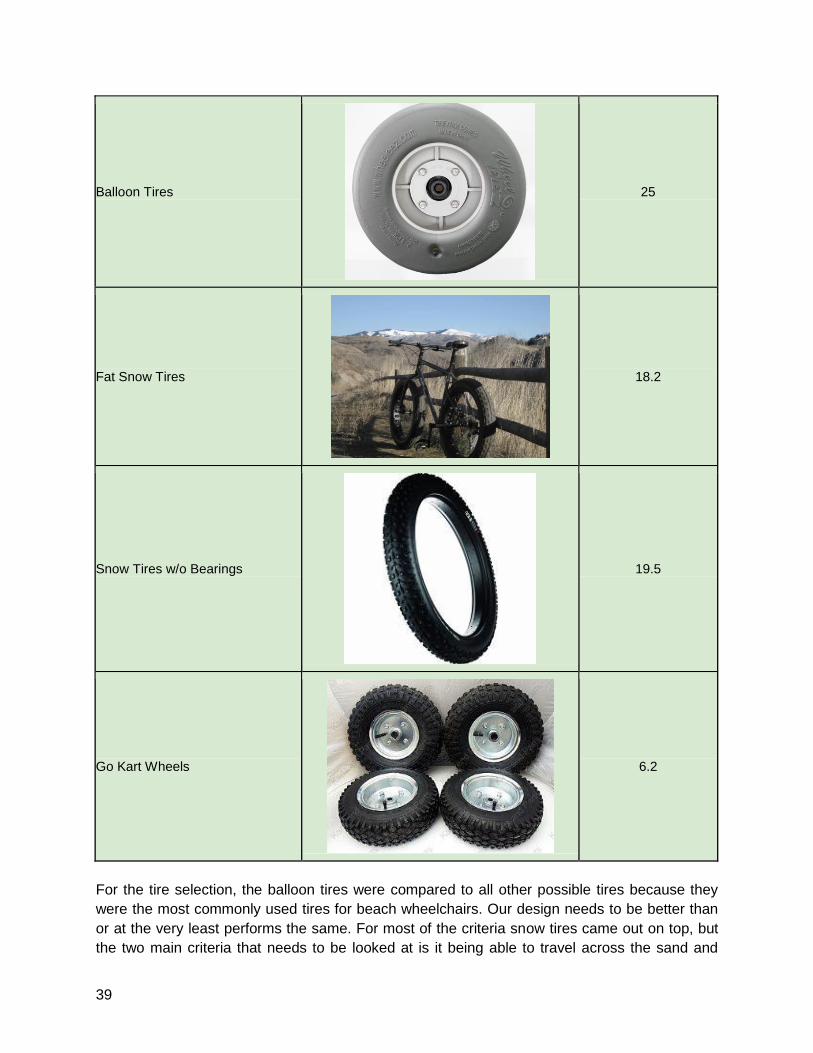
Balloon Tires
25
Fat Snow Tires
18.2
Snow Tires w/o Bearings
19.5
Go Kart Wheels
6.2
For the tire selection, the balloon tires were compared to all other possible tires because they
were the most commonly used tires for beach wheelchairs. Our design needs to be better than
or at the very least performs the same. For most of the criteria snow tires came out on top, but
the two main criteria that needs to be looked at is it being able to travel across the sand and
40
being water proof because they fall under specific requirements stated by the user. The other
criteria are mostly bonuses. I figured that the balloon tires would end up being the best choice
because all other choices were worse in at least one of the two main criteria. The wide snow
tires are very speculative and could still be an option because they have not been tested and
nobody in our group has experience using them. When developing our final design, we figure
that because of the weight and unlikeliness of the snow tires to travel across the sand any better
than the balloon tires, the balloon tires would ultimately be the best choice. The choice also
became more obvious when we found out later that cuts in the balloon tire can be fixed with a
soldering iron and that the vehicle needed to float (balloon tires being the only floatable tires).
Floating
To make the wheelchair float and stable in the water we looked at different options. The ideas
we had were all pretty good but we couldn't really test them, so the rating is very subjective. Our
first thought was to put some air bags to the wheelchair that might have worked out for the
floating aspect but we might still get troubles in getting it stable enough. Putting some floatable
material under the armrests was the next idea, it wasn't rating high enough. We had two ideas
with a very high rating, both pretty close. Buoys on folding rods would provide enough floating
force and also stability as the folding rods would function as a huge lever to get it stable and
maybe even controllable. The idea to use only the already existing balloon tires were the
second best rated. As both concepts were pretty close we decided to give the balloon tires a
shot and test it out. If the balloon tires don't work out we still could easily add the buoys on
folding rods. So the winner of this subsystem are the Balloon Tires, rated as shown in Table
4.10 below, with Buoys on folding rods as alternative.
Table 4.10: Floating subsystem matrix and final results.
Criteria Weight (1-5) Rory Alex Sam Joshua Marco Marvin Max Benedikt
Durability 4 2 2 2 2 2 2 2 2
Weight 2 1 1 1 1 1 1 1 1
Transportability 4 2 2 1 2 2 2 1 1
Floating Force 3 0 0 2 1 0 -1 0 -1
Stability 5 -1 -1 -1 -2 -2 0 -2 -2
Total - 13 13 15 11 8 15 4 1
AVG Total 8
Water Propulsion
If we can get the user with the wheelchair into the water they need to have some option for
movement and control in it. Ideas for that were to give the user oars, maybe attached
41
somewhere in the back behind the backrest. That would have been the easiest option. Another
opportunity was to fit a propeller to the wheelchair, which would have been extra weight. We
could also use some kind of paddle wheels, they are excellent in the water and on the sand but
will make problems with getting on the street and might even get destroyed there because of the
hard surface. The last idea was to create a paddle attachment to the lever drive system, which
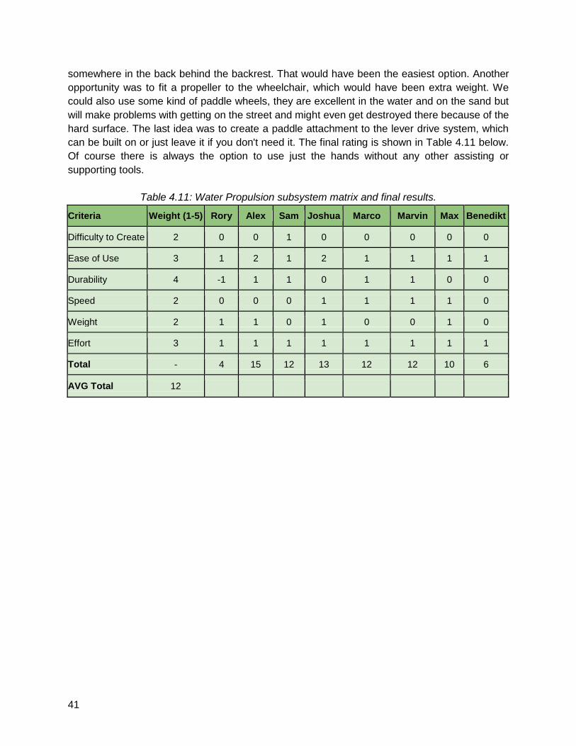
can be built on or just leave it if you don't need it. The final rating is shown in Table 4.11 below.
Of course there is always the option to use just the hands without any other assisting or
supporting tools.
Table 4.11: Water Propulsion subsystem matrix and final results.
Criteria Weight (1-5) Rory Alex Sam Joshua Marco Marvin Max Benedikt
Difficulty to Create 2 0 0 1 0 0 0 0 0
Ease of Use 3 1 2 1 2 1 1 1 1
Durability 4 -1 1 1 0 1 1 0 0
Speed 2 0 0 0 1 1 1 1 0
Weight 2 1 1 0 1 0 0 1 0
Effort 3 1 1 1 1 1 1 1 1
Total - 4 15 12 13 12 12 10 6
AVG Total 12
42
5 - Initial Whole Concepts
Avila Wheelchair Designs
Two chairs were tested at Avila Beach as described earlier. Both of these chairs are listed in
this section as we used them as a datum and as inspiration for our initial whole concepts.
The first of these chairs was the Natural Access Landeez™ seen in Figure 1.1. This chair was
simple and featured very little adjustability. It provided no way for the user to power themselves
requiring significant effort from an assistant to push the user. In addition, when entering the
water the chair was incredibly unstable and had no means of propulsion.
The second chair was an electric chair seen in Figure 1.2. This chair was fast and easy to use
moving around on the sand. Unfortunately, this chair was not able to enter the water requiring
the user to miss a large part of the beach experience. In addition, this chair provided no
exercise for the person using it.
Neither of the chairs at Avila provided an easy way for the user to access the sand. An assistant
would be required to lift the user from the chair to the sand and vice versa. Though both chairs
functioned well, they do not satisfy our customer requirement of providing the full beach
experience. Regardless, these designs were scored in our initial whole concept matrix.
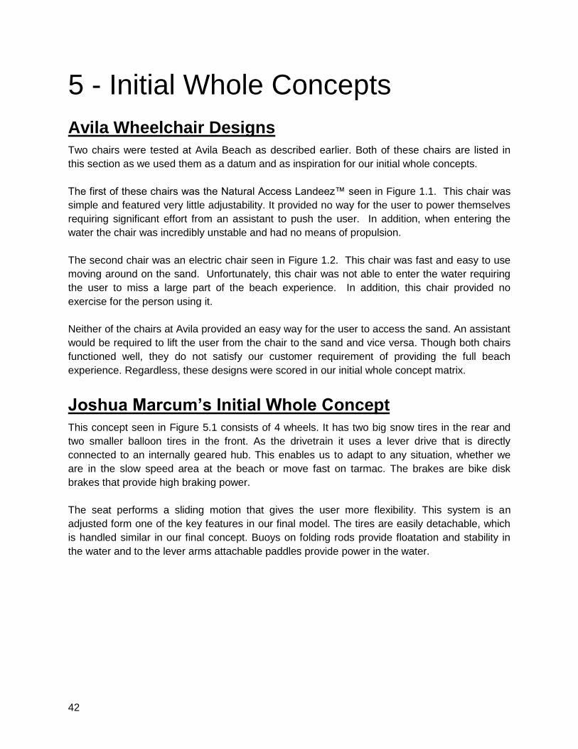
Joshua Marcum’s Initial Whole Concept
This concept seen in Figure 5.1 consists of 4 wheels. It has two big snow tires in the rear and
two smaller balloon tires in the front. As the drivetrain it uses a lever drive that is directly
connected to an internally geared hub. This enables us to adapt to any situation, whether we
are in the slow speed area at the beach or move fast on tarmac. The brakes are bike disk
brakes that provide high braking power.
The seat performs a sliding motion that gives the user more flexibility. This system is an
adjusted form one of the key features in our final model. The tires are easily detachable, which
is handled similar in our final concept. Buoys on folding rods provide floatation and stability in
the water and to the lever arms attachable paddles provide power in the water.
43
Figure 5.1: Joshua’s initial whole concept.
Sam Coyne’s Initial Whole Concept
For this design, the main subsystems that were used included the following:
● 4 Balloon Tires
● Ratcheting Drive System
● Bike Hand Brakes
● Spring Loaded/Mechanical Device for Seat Lowering
● Adjustable Seat Backing and Arm Rests
● Cup holders and Pouch on Back of Seat
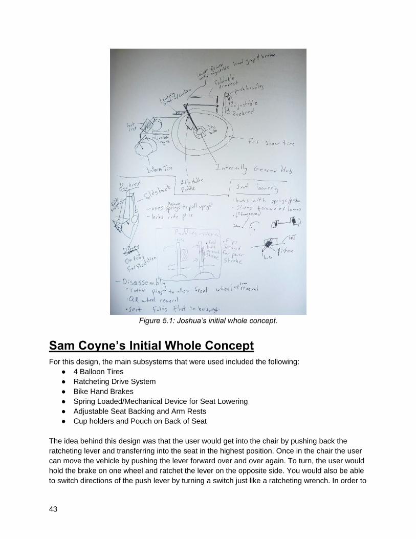
The idea behind this design was that the user would get into the chair by pushing back the
ratcheting lever and transferring into the seat in the highest position. Once in the chair the user
can move the vehicle by pushing the lever forward over and over again. To turn, the user would
hold the brake on one wheel and ratchet the lever on the opposite side. You would also be able
to switch directions of the push lever by turning a switch just like a ratcheting wrench. In order to
44
be close to the sand and have a lower center of gravity when floating the seat would be lowered
by pushing a notch out of a groove and having the user’s weight on a spring lower the seat. To
let the seat come up, the user would push up on the armrests and let the spring push up the
seat till it pops in place.
Figure 5.2: Sam’s initial whole concept.
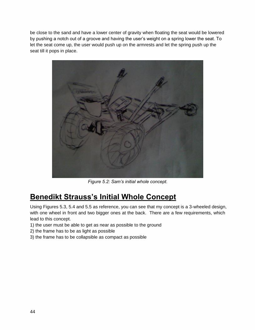
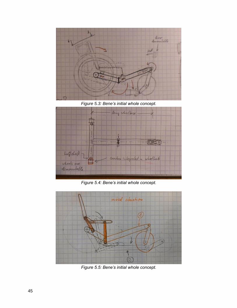
Benedikt Strauss’s Initial Whole Concept
Using Figures 5.3, 5.4 and 5.5 as reference, you can see that my concept is a 3-wheeled design,
with one wheel in front and two bigger ones at the back. There are a few requirements, which
lead to this concept.
1) the user must be able to get as near as possible to the ground
2) the frame has to be as light as possible
3) the frame has to be collapsible as compact as possible
45
Figure 5.3: Bene’s initial whole concept.
Figure 5.4: Bene’s initial whole concept.
Figure 5.5: Bene’s initial whole concept.
46
As you can see on the picture above, the front wheel is able to turn around, what makes the
frame come down close to the ground. To do this you take the lever on the front wheel and pull.
This action causes the seat to slide down allowing the driver to reach the ground. To get up
again, the user pushes the lever on the front wheel forwards, which consequently moves the
seat backwards, which makes the whole assembly move back to its original position. The
collapsing is supported by the spring, linked to the front wheel. The frame has the minimum
components, making it the lightest design. To get the assembly in the trunk, the frame collapses,
like it can be seen in the picture above. Some clamps are freed, then the front part can be
turned around under the seat, additionally the seat can be collapsed, which makes the whole
compact for transport.
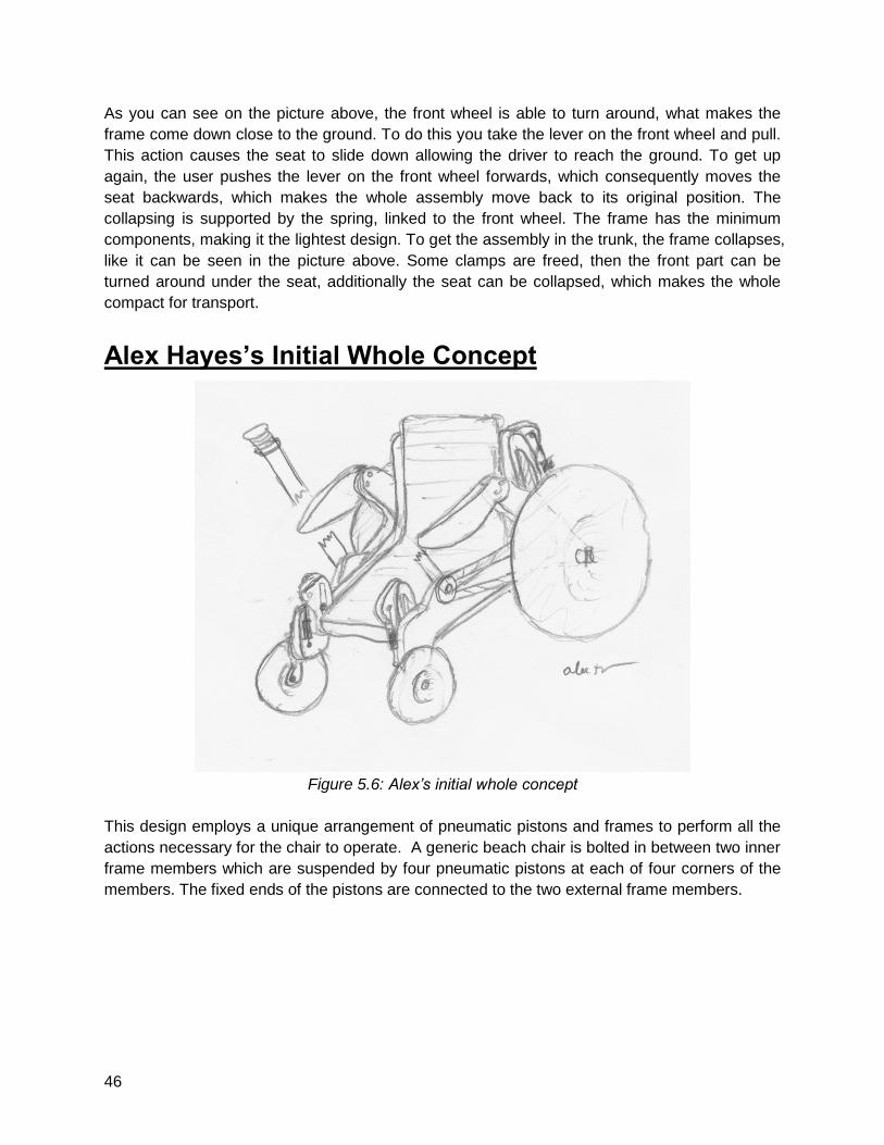
Alex Hayes’s Initial Whole Concept
Figure 5.6: Alex’s initial whole concept
This design employs a unique arrangement of pneumatic pistons and frames to perform all the
actions necessary for the chair to operate. A generic beach chair is bolted in between two inner
frame members which are suspended by four pneumatic pistons at each of four corners of the
members. The fixed ends of the pistons are connected to the two external frame members.

47
Figure 5.7: Exploded view of Alex’s concept
To help eliminate lateral forces on the pneumatic pistons, two pins protrude out of the side of
each external frame member. Those pins mate with the corresponding slots on the inner frame
members. This pin and slot design provides a fixed linear motion of the inner members with
respect to the external frame, as well as a support that will sustain all lateral forces that would
otherwise be sustained by the pistons.
Figure 5.8: Side profile of concept showing the raising and lowering aspects
48
The external frames attach to the main axle which holds the driving wheels and the smaller
frontal cantered wheels. As such, it is in contact with the ground with allows for the following
feature: the internal frame moves up and down based on the user’s weight on the chair. As the
person sits in the chair, the user can pull a lever which allows the pistons to lower under the
weight of the person, much like a conventional office chair. Similarly, the user can push up on
handles attached to the external frame to reduce their weight on the chair, allowing the pistons
to push the chair and inner members back up. As a result, the user has control over height
adjustment of the chair and can lower the chair all the way to the sand. As an added bonus, the
pneumatic springs act as a miniature suspension system for the chair.
The drive system consists of two ratcheting levers on each side of the external frame which
drive pulleys that accept toothed belts. The user pushes forward on the lever to propel them
forward. A switch will be available to reverse the lever-action to drive the chair backwards as
well. Each lever pulley is connected via toothed belt to a pulley that is directly attached to one
of the rear drive wheels. This allows the user to operate one wheel at a time for turning. The
cantered wheels in front allow for easy turning as well.
The armrests will be able to raise and lower to provide for easier seat transfer via transfer board.
Furthermore, the armrests will be hollow plastic parts that hold air for additional flotation. The
front end of the chair is open to allow the user to get out of the front of the chair while in the
lowered position if desired. The rear wheels are removable and can be replaced with a simple
pin connection. The same applies to the front cantered wheels. The braking mechanism will
consist of disk brakes operated by hydraulic fluid. The levers will each have a handle to pull on
when braking is desired. The seat will be able to recline and will be placed on the inner frames
such that the back of the seat will come in contact with the rear axle and make a 45 degree
angle with the ground when it is completely lowered to the ground.
There are some inherent flaws with design, however. For example, the unique frame designs
require custom fabrication, which could become overly complex and expensive for the scope of
this project. Furthermore, the system is requires several large complete members that may be
difficult to fit into a vehicle easily.
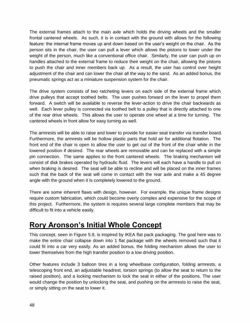
Rory Aronson’s Initial Whole Concept
This concept, seen in Figure 5.9, is inspired by IKEA flat pack packaging. The goal here was to
make the entire chair collapse down into 1 flat package with the wheels removed such that it
could fit into a car very easily. As an added bonus, the folding mechanism allows the user to
lower themselves from the high transfer position to a low driving position.
Other features include 3 balloon tires in a long wheelbase configuration, folding armrests, a
telescoping front end, an adjustable headrest, torsion springs (to allow the seat to return to the
raised position), and a locking mechanism to lock the seat in either of the positions. The user
would change the position by unlocking the seat, and pushing on the armrests to raise the seat,
or simply sitting on the seat to lower it.
49
We learned from this design that a folding backrest will be a necessary feature to fit the device
in the car, and that lowering the user only halfway to the ground is simply inadequate to reach
our requirement of providing the full beach experience.
Figure 5.9: Rory’s initial whole concept.
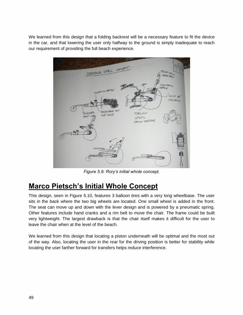
Marco Pietsch’s Initial Whole Concept
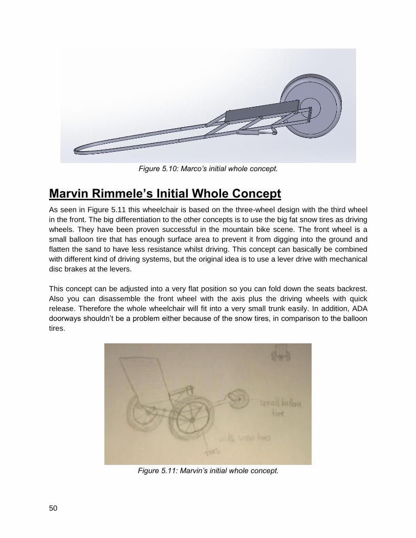
This design, seen in Figure 5.10, features 3 balloon tires with a very long wheelbase. The user
sits in the back where the two big wheels are located. One small wheel is added in the front.
The seat can move up and down with the lever design and is powered by a pneumatic spring.
Other features include hand cranks and a rim belt to move the chair. The frame could be built
very lightweight. The largest drawback is that the chair itself makes it difficult for the user to
leave the chair when at the level of the beach.
We learned from this design that locating a piston underneath will be optimal and the most out
of the way. Also, locating the user in the rear for the driving position is better for stability while
locating the user farther forward for transfers helps reduce interference.
50
Figure 5.10: Marco’s initial whole concept.
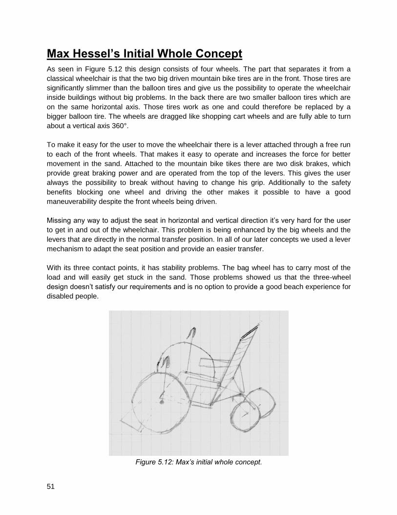
Marvin Rimmele’s Initial Whole Concept
As seen in Figure 5.11 this wheelchair is based on the three-wheel design with the third wheel
in the front. The big differentiation to the other concepts is to use the big fat snow tires as driving
wheels. They have been proven successful in the mountain bike scene. The front wheel is a
small balloon tire that has enough surface area to prevent it from digging into the ground and
flatten the sand to have less resistance whilst driving. This concept can basically be combined
with different kind of driving systems, but the original idea is to use a lever drive with mechanical
disc brakes at the levers.
This concept can be adjusted into a very flat position so you can fold down the seats backrest.
Also you can disassemble the front wheel with the axis plus the driving wheels with quick
release. Therefore the whole wheelchair will fit into a very small trunk easily. In addition, ADA
doorways shouldn’t be a problem either because of the snow tires, in comparison to the balloon
tires.
Figure 5.11: Marvin’s initial whole concept.
51
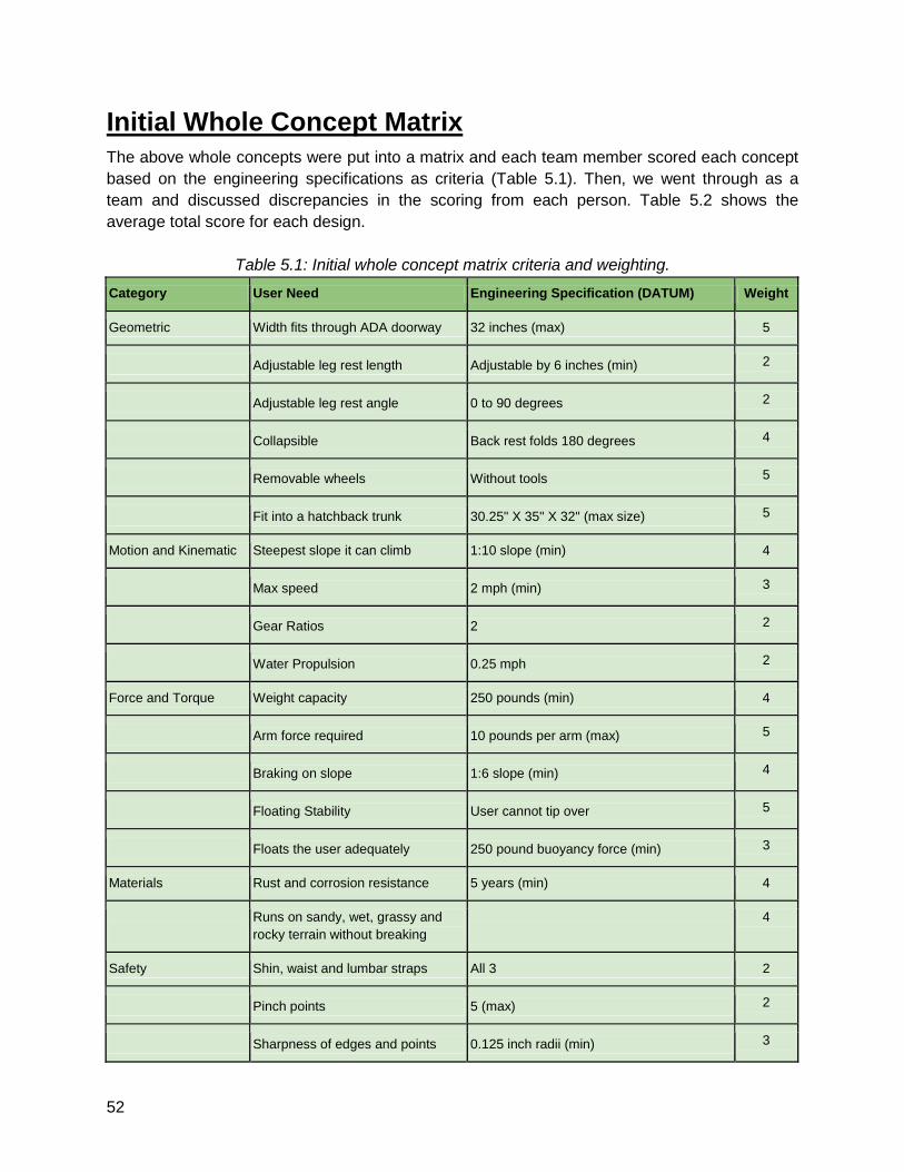
Max Hessel’s Initial Whole Concept
As seen in Figure 5.12 this design consists of four wheels. The part that separates it from a
classical wheelchair is that the two big driven mountain bike tires are in the front. Those tires are
significantly slimmer than the balloon tires and give us the possibility to operate the wheelchair
inside buildings without big problems. In the back there are two smaller balloon tires which are
on the same horizontal axis. Those tires work as one and could therefore be replaced by a
bigger balloon tire. The wheels are dragged like shopping cart wheels and are fully able to turn
about a vertical axis 360°.
To make it easy for the user to move the wheelchair there is a lever attached through a free run
to each of the front wheels. That makes it easy to operate and increases the force for better
movement in the sand. Attached to the mountain bike tikes there are two disk brakes, which
provide great braking power and are operated from the top of the levers. This gives the user
always the possibility to break without having to change his grip. Additionally to the safety
benefits blocking one wheel and driving the other makes it possible to have a good
maneuverability despite the front wheels being driven.
Missing any way to adjust the seat in horizontal and vertical direction it’s very hard for the user
to get in and out of the wheelchair. This problem is being enhanced by the big wheels and the
levers that are directly in the normal transfer position. In all of our later concepts we used a lever
mechanism to adapt the seat position and provide an easier transfer.
With its three contact points, it has stability problems. The bag wheel has to carry most of the
load and will easily get stuck in the sand. Those problems showed us that the three-wheel
design doesn’t satisfy our requirements and is no option to provide a good beach experience for
disabled people.
Figure 5.12: Max’s initial whole concept.
52
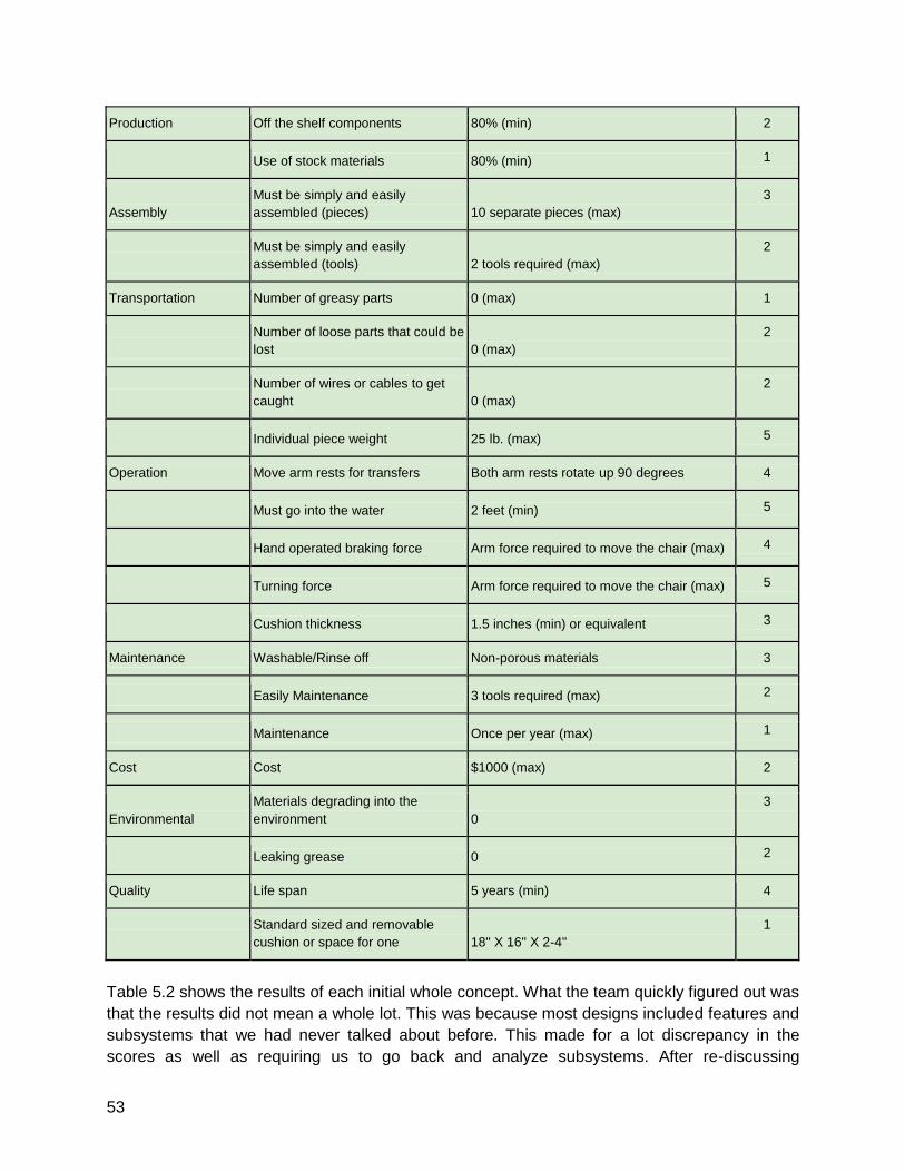
Initial Whole Concept Matrix
The above whole concepts were put into a matrix and each team member scored each concept
based on the engineering specifications as criteria (Table 5.1). Then, we went through as a
team and discussed discrepancies in the scoring from each person. Table 5.2 shows the
average total score for each design.
Table 5.1: Initial whole concept matrix criteria and weighting.
Category User Need Engineering Specification (DATUM) Weight
Geometric Width fits through ADA doorway 32 inches (max) 5
Adjustable leg rest length Adjustable by 6 inches (min) 2
Adjustable leg rest angle 0 to 90 degrees 2
Collapsible Back rest folds 180 degrees 4
Removable wheels Without tools 5
Fit into a hatchback trunk 30.25" X 35" X 32" (max size) 5
Motion and Kinematic Steepest slope it can climb 1:10 slope (min) 4
Max speed 2 mph (min) 3
Gear Ratios 2 2
Water Propulsion 0.25 mph 2
Force and Torque Weight capacity 250 pounds (min) 4
Arm force required 10 pounds per arm (max) 5
Braking on slope 1:6 slope (min) 4
Floating Stability User cannot tip over 5
Floats the user adequately 250 pound buoyancy force (min) 3
Materials Rust and corrosion resistance 5 years (min) 4
Runs on sandy, wet, grassy and
rocky terrain without breaking 4
Safety Shin, waist and lumbar straps All 3 2
Pinch points 5 (max) 2
Sharpness of edges and points 0.125 inch radii (min) 3
53
Production Off the shelf components 80% (min) 2
Use of stock materials 80% (min) 1
Assembly Must be simply and easily
assembled (pieces) 10 separate pieces (max) 3
Must be simply and easily
assembled (tools) 2 tools required (max) 2
Transportation Number of greasy parts 0 (max) 1
Number of loose parts that could be
lost 0 (max) 2
Number of wires or cables to get
caught 0 (max) 2
Individual piece weight 25 lb. (max) 5
Operation Move arm rests for transfers Both arm rests rotate up 90 degrees 4
Must go into the water 2 feet (min) 5
Hand operated braking force Arm force required to move the chair (max) 4
Turning force Arm force required to move the chair (max) 5
Cushion thickness 1.5 inches (min) or equivalent 3
Maintenance Washable/Rinse off Non-porous materials 3
Easily Maintenance 3 tools required (max) 2
Maintenance Once per year (max) 1
Cost Cost $1000 (max) 2
Environmental Materials degrading into the
environment 0 3
Leaking grease 0 2
Quality Life span 5 years (min) 4
Standard sized and removable
cushion or space for one 18" X 16" X 2-4" 1
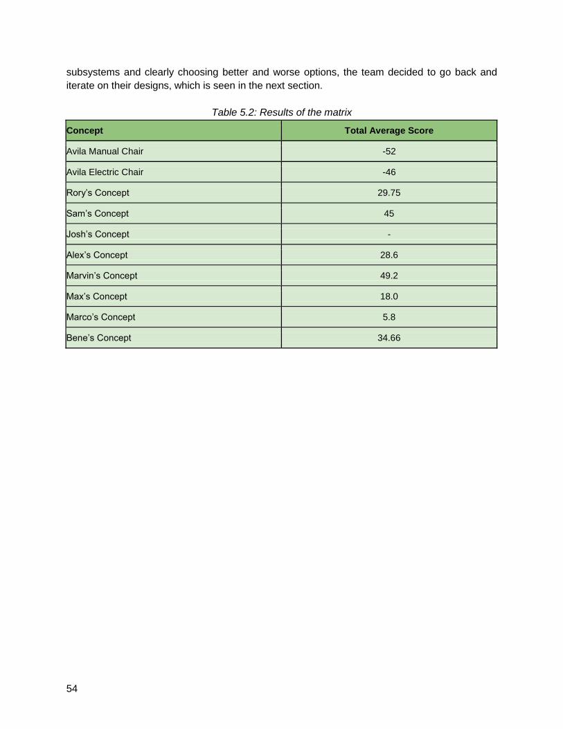
Table 5.2 shows the results of each initial whole concept. What the team quickly figured out was
that the results did not mean a whole lot. This was because most designs included features and
subsystems that we had never talked about before. This made for a lot discrepancy in the
scores as well as requiring us to go back and analyze subsystems. After re-discussing
54
subsystems and clearly choosing better and worse options, the team decided to go back and
iterate on their designs, which is seen in the next section.
Table 5.2: Results of the matrix
Concept Total Average Score
Avila Manual Chair -52
Avila Electric Chair -46
Rory’s Concept 29.75
Sam’s Concept 45
Josh’s Concept -
Alex’s Concept 28.6
Marvin’s Concept 49.2
Max’s Concept 18.0
Marco’s Concept 5.8
Bene’s Concept 34.66
55
6 - Iterated Whole Concepts Based on the matrix results and discussion from the initial whole concepts, the team iterated the
designs and came up with new designs to be further evaluated. Most designs were very similar
and we chose two to be considered for the final concept. These two are detailed below along
with a description of the final selection process.
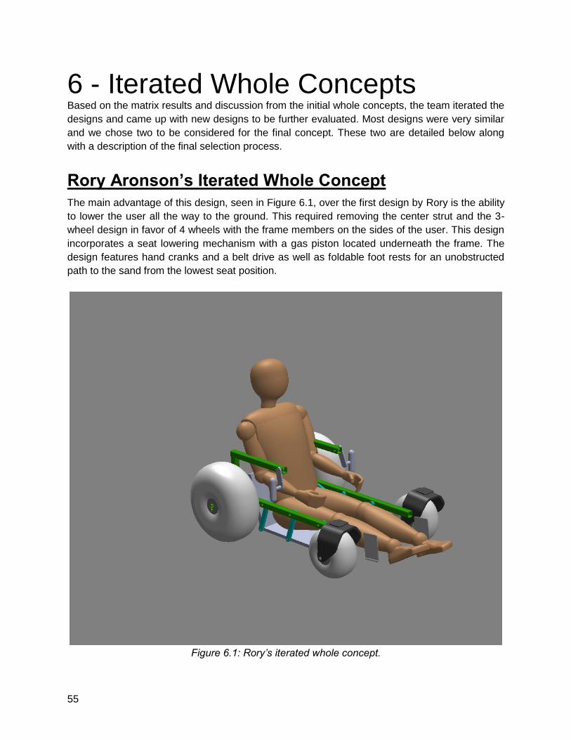
Rory Aronson’s Iterated Whole Concept
The main advantage of this design, seen in Figure 6.1, over the first design by Rory is the ability
to lower the user all the way to the ground. This required removing the center strut and the 3-
wheel design in favor of 4 wheels with the frame members on the sides of the user. This design
incorporates a seat lowering mechanism with a gas piston located underneath the frame. The
design features hand cranks and a belt drive as well as foldable foot rests for an unobstructed
path to the sand from the lowest seat position.
Figure 6.1: Rory’s iterated whole concept.
56
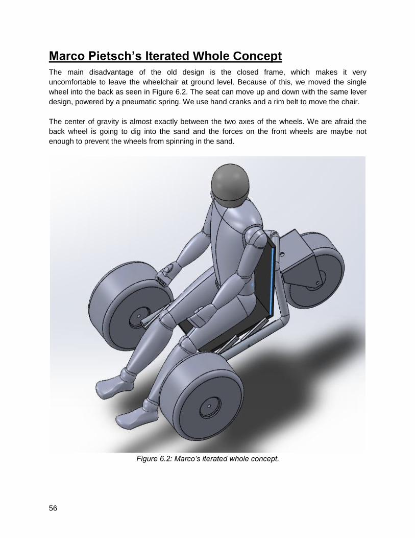
Marco Pietsch’s Iterated Whole Concept
The main disadvantage of the old design is the closed frame, which makes it very
uncomfortable to leave the wheelchair at ground level. Because of this, we moved the single
wheel into the back as seen in Figure 6.2. The seat can move up and down with the same lever
design, powered by a pneumatic spring. We use hand cranks and a rim belt to move the chair.
The center of gravity is almost exactly between the two axes of the wheels. We are afraid the
back wheel is going to dig into the sand and the forces on the front wheels are maybe not
enough to prevent the wheels from spinning in the sand.
Figure 6.2: Marco’s iterated whole concept.
57
Final Selection Process
The team got itself into quite the time crunch and made the final concept decision just 2 days
prior to this report being submitted. We had a videoconference over the weekend and talked
about the advantages and disadvantages of the two designs. The designs were very similar in
many aspects, but the following reasons are what made the team choose Rory’s design.
● Marco’s design would be less stable due to only having 3 wheels.
● Marco’s design places too much of the users’ weight on the steering wheel.
○ This causes this smaller wheel to dig into the ground and makes steering more
difficult.
○ This also causes less weight on the drive wheels and a potential loss of traction.
● Rory’s design places more of the users’ weight on the driving wheels.
○ This allows for greater traction and easier steering.
● Marco’s frame design is not very collapsible, making it more difficult to fit into a car.
58
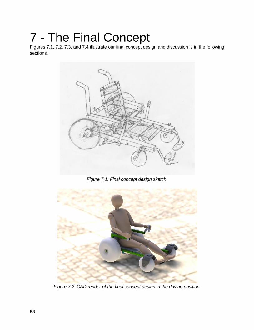
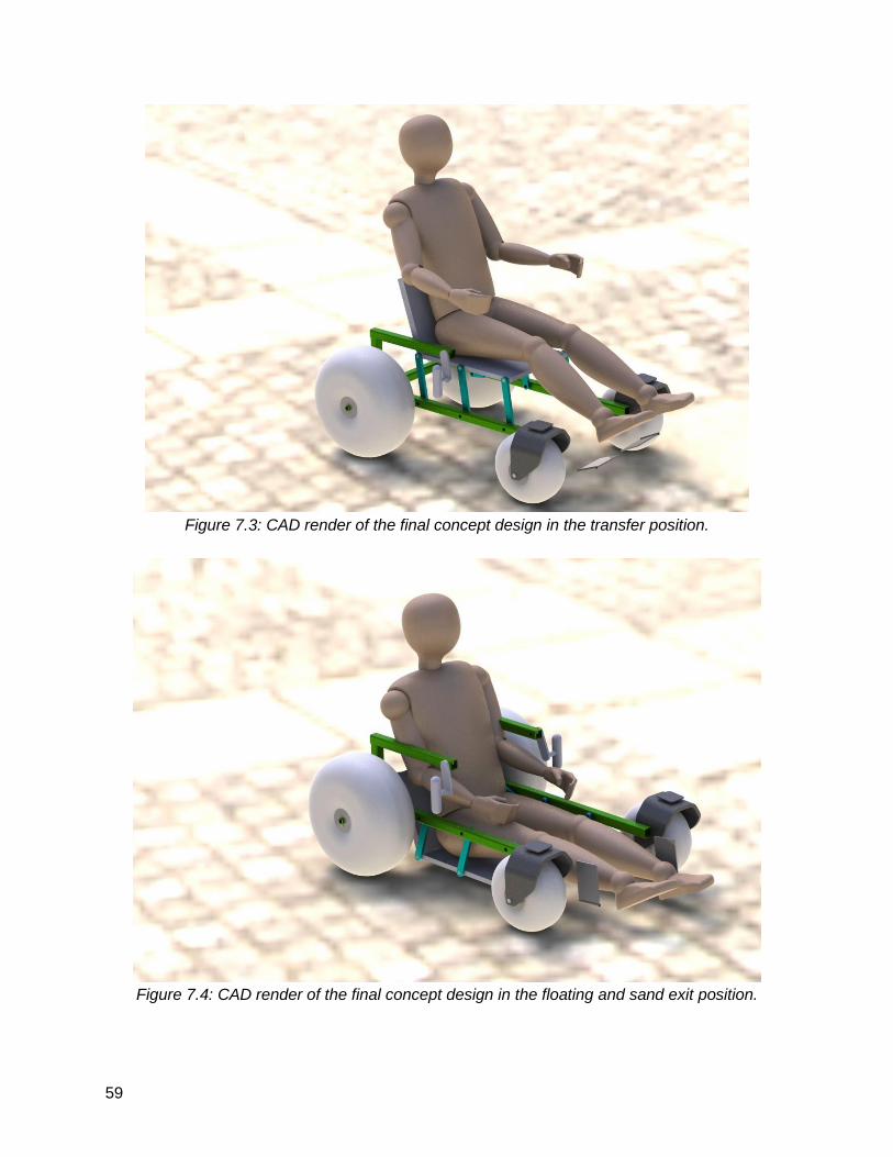
7 - The Final Concept Figures 7.1, 7.2, 7.3, and 7.4 illustrate our final concept design and discussion is in the following
sections.
Figure 7.1: Final concept design sketch.
Figure 7.2: CAD render of the final concept design in the driving position.
59
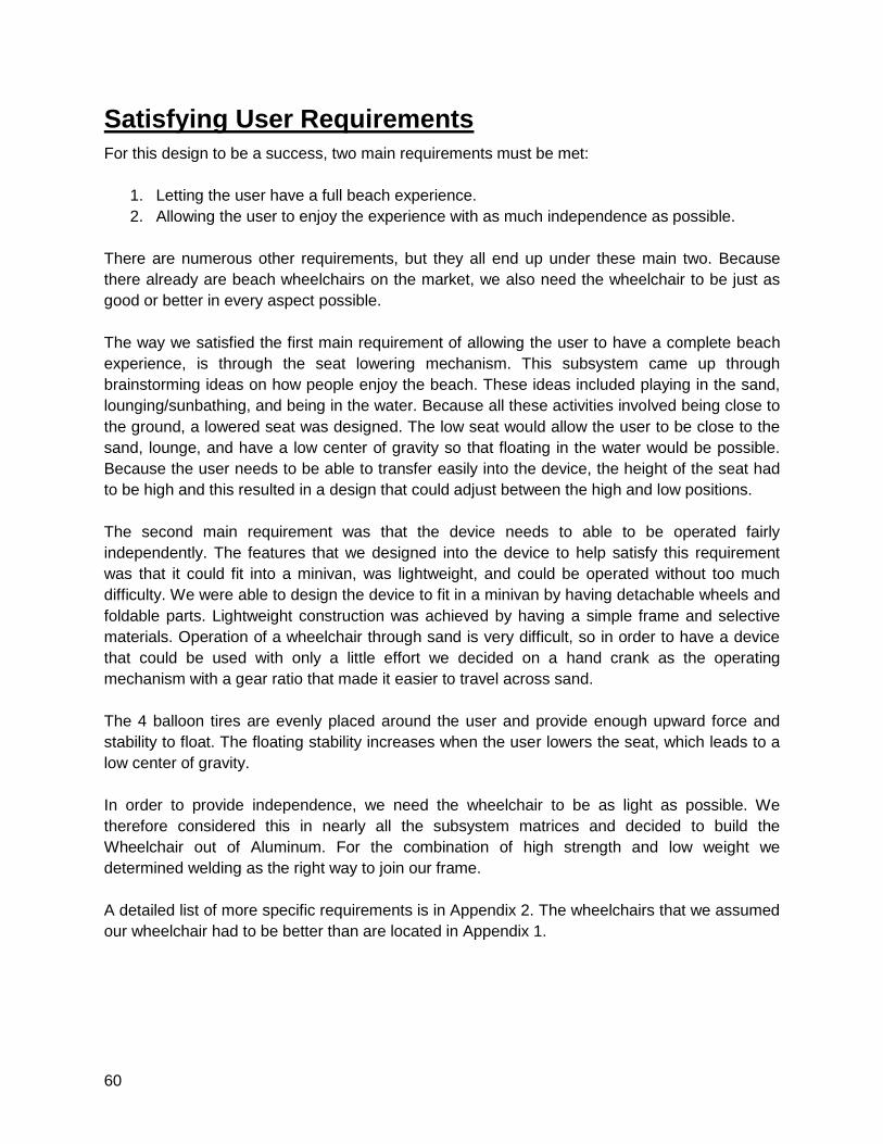
Figure 7.3: CAD render of the final concept design in the transfer position.
Figure 7.4: CAD render of the final concept design in the floating and sand exit position.
60
Satisfying User Requirements
For this design to be a success, two main requirements must be met:
1. Letting the user have a full beach experience.
2. Allowing the user to enjoy the experience with as much independence as possible.
There are numerous other requirements, but they all end up under these main two. Because
there already are beach wheelchairs on the market, we also need the wheelchair to be just as
good or better in every aspect possible.
The way we satisfied the first main requirement of allowing the user to have a complete beach
experience, is through the seat lowering mechanism. This subsystem came up through
brainstorming ideas on how people enjoy the beach. These ideas included playing in the sand,
lounging/sunbathing, and being in the water. Because all these activities involved being close to
the ground, a lowered seat was designed. The low seat would allow the user to be close to the
sand, lounge, and have a low center of gravity so that floating in the water would be possible.
Because the user needs to be able to transfer easily into the device, the height of the seat had
to be high and this resulted in a design that could adjust between the high and low positions.
The second main requirement was that the device needs to able to be operated fairly
independently. The features that we designed into the device to help satisfy this requirement
was that it could fit into a minivan, was lightweight, and could be operated without too much
difficulty. We were able to design the device to fit in a minivan by having detachable wheels and
foldable parts. Lightweight construction was achieved by having a simple frame and selective
materials. Operation of a wheelchair through sand is very difficult, so in order to have a device
that could be used with only a little effort we decided on a hand crank as the operating
mechanism with a gear ratio that made it easier to travel across sand.
The 4 balloon tires are evenly placed around the user and provide enough upward force and
stability to float. The floating stability increases when the user lowers the seat, which leads to a
low center of gravity.
In order to provide independence, we need the wheelchair to be as light as possible. We
therefore considered this in nearly all the subsystem matrices and decided to build the
Wheelchair out of Aluminum. For the combination of high strength and low weight we
determined welding as the right way to join our frame.
A detailed list of more specific requirements is in Appendix 2. The wheelchairs that we assumed
our wheelchair had to be better than are located in Appendix 1.
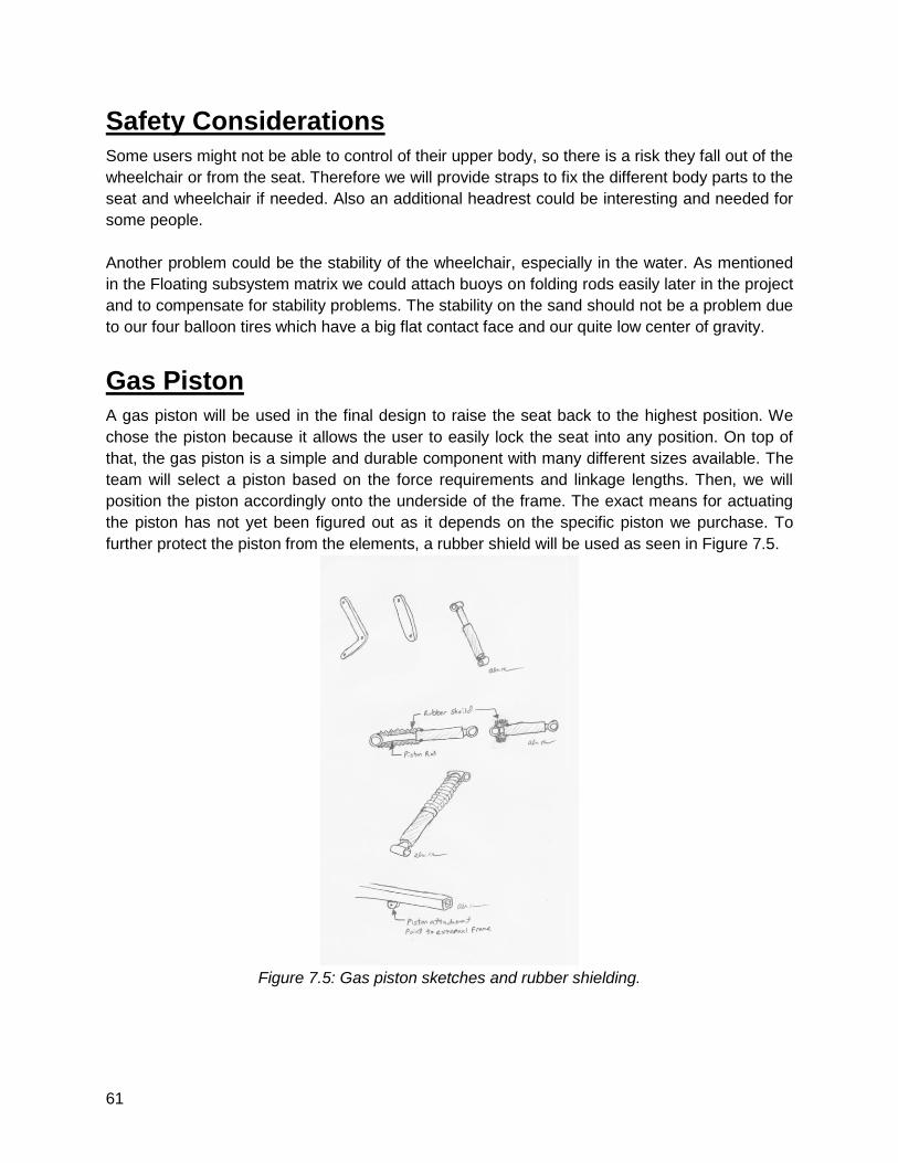
61
Safety Considerations
Some users might not be able to control of their upper body, so there is a risk they fall out of the
wheelchair or from the seat. Therefore we will provide straps to fix the different body parts to the
seat and wheelchair if needed. Also an additional headrest could be interesting and needed for
some people.
Another problem could be the stability of the wheelchair, especially in the water. As mentioned
in the Floating subsystem matrix we could attach buoys on folding rods easily later in the project
and to compensate for stability problems. The stability on the sand should not be a problem due
to our four balloon tires which have a big flat contact face and our quite low center of gravity.
Gas Piston
A gas piston will be used in the final design to raise the seat back to the highest position. We
chose the piston because it allows the user to easily lock the seat into any position. On top of
that, the gas piston is a simple and durable component with many different sizes available. The
team will select a piston based on the force requirements and linkage lengths. Then, we will
position the piston accordingly onto the underside of the frame. The exact means for actuating
the piston has not yet been figured out as it depends on the specific piston we purchase. To
further protect the piston from the elements, a rubber shield will be used as seen in Figure 7.5.
Figure 7.5: Gas piston sketches and rubber shielding.
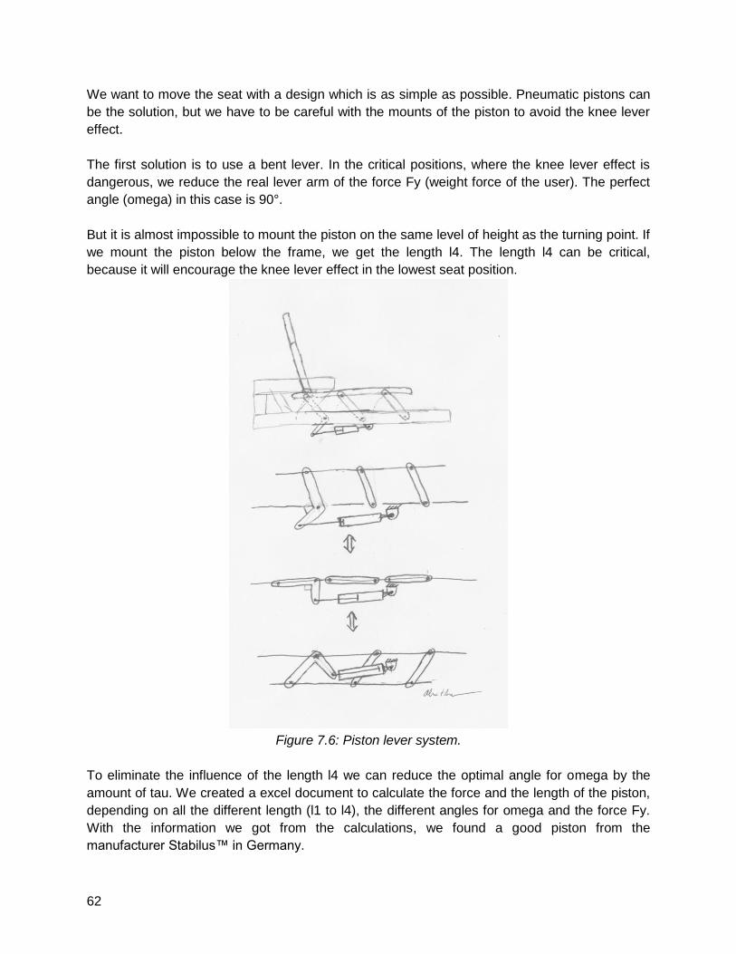
62
We want to move the seat with a design which is as simple as possible. Pneumatic pistons can
be the solution, but we have to be careful with the mounts of the piston to avoid the knee lever
effect.
The first solution is to use a bent lever. In the critical positions, where the knee lever effect is
dangerous, we reduce the real lever arm of the force Fy (weight force of the user). The perfect
angle (omega) in this case is 90°.
But it is almost impossible to mount the piston on the same level of height as the turning point. If
we mount the piston below the frame, we get the length l4. The length l4 can be critical,
because it will encourage the knee lever effect in the lowest seat position.
Figure 7.6: Piston lever system.
To eliminate the influence of the length l4 we can reduce the optimal angle for omega by the
amount of tau. We created a excel document to calculate the force and the length of the piston,
depending on all the different length (l1 to l4), the different angles for omega and the force Fy.
With the information we got from the calculations, we found a good piston from the
manufacturer Stabilus™ in Germany.
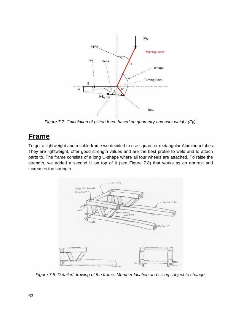
63
Figure 7.7: Calculation of piston force based on geometry and user weight (Fy).
Frame
To get a lightweight and reliable frame we decided to use square or rectangular Aluminum tubes.
They are lightweight, offer good strength values and are the best profile to weld and to attach
parts to. The frame consists of a long U-shape where all four wheels are attached. To raise the
strength, we added a second U on top of it (see Figure 7.8) that works as an armrest and
increases the strength.
Figure 7.8: Detailed drawing of the frame. Member location and sizing subject to change.
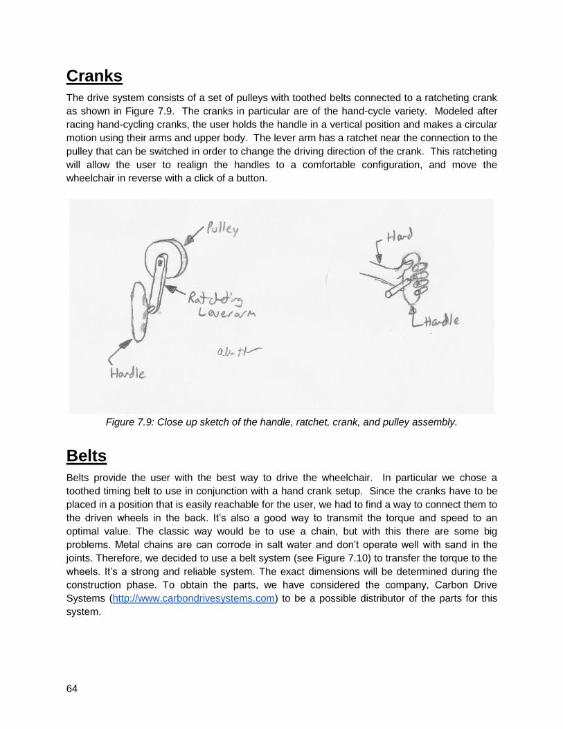
64
Cranks
The drive system consists of a set of pulleys with toothed belts connected to a ratcheting crank
as shown in Figure 7.9. The cranks in particular are of the hand-cycle variety. Modeled after
racing hand-cycling cranks, the user holds the handle in a vertical position and makes a circular
motion using their arms and upper body. The lever arm has a ratchet near the connection to the
pulley that can be switched in order to change the driving direction of the crank. This ratcheting
will allow the user to realign the handles to a comfortable configuration, and move the
wheelchair in reverse with a click of a button.
Figure 7.9: Close up sketch of the handle, ratchet, crank, and pulley assembly.
Belts
Belts provide the user with the best way to drive the wheelchair. In particular we chose a
toothed timing belt to use in conjunction with a hand crank setup. Since the cranks have to be
placed in a position that is easily reachable for the user, we had to find a way to connect them to
the driven wheels in the back. It’s also a good way to transmit the torque and speed to an
optimal value. The classic way would be to use a chain, but with this there are some big
problems. Metal chains are can corrode in salt water and don’t operate well with sand in the
joints. Therefore, we decided to use a belt system (see Figure 7.10) to transfer the torque to the
wheels. It’s a strong and reliable system. The exact dimensions will be determined during the
construction phase. To obtain the parts, we have considered the company, Carbon Drive
Systems (http://www.carbondrivesystems.com) to be a possible distributor of the parts for this
system.
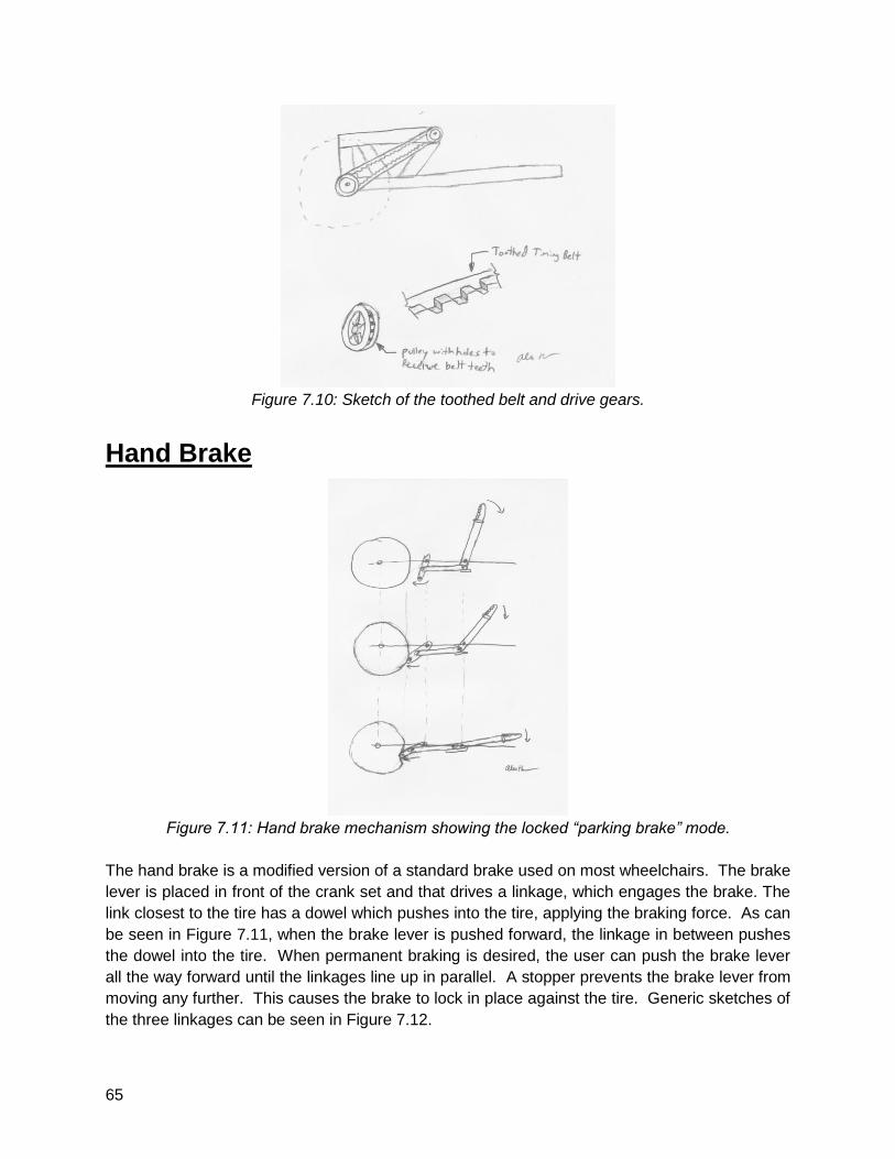
65
Figure 7.10: Sketch of the toothed belt and drive gears.
Hand Brake
Figure 7.11: Hand brake mechanism showing the locked “parking brake” mode.
The hand brake is a modified version of a standard brake used on most wheelchairs. The brake
lever is placed in front of the crank set and that drives a linkage, which engages the brake. The
link closest to the tire has a dowel which pushes into the tire, applying the braking force. As can
be seen in Figure 7.11, when the brake lever is pushed forward, the linkage in between pushes
the dowel into the tire. When permanent braking is desired, the user can push the brake lever
all the way forward until the linkages line up in parallel. A stopper prevents the brake lever from
moving any further. This causes the brake to lock in place against the tire. Generic sketches of
the three linkages can be seen in Figure 7.12.
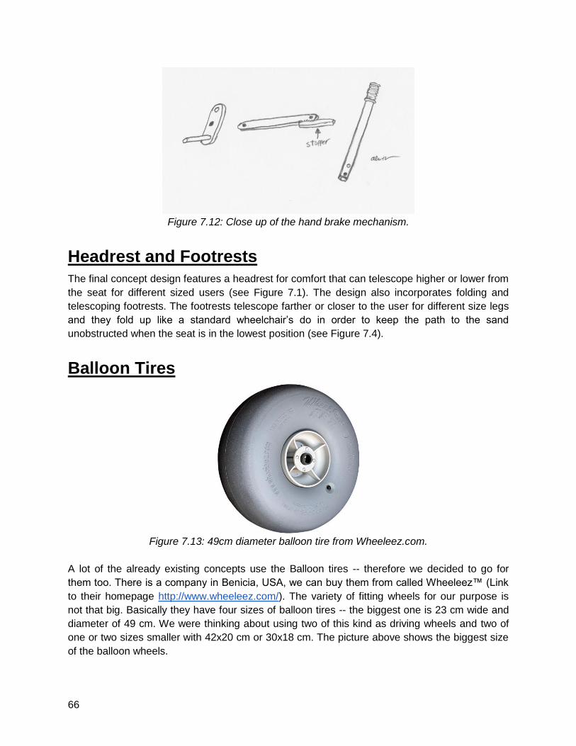
66
Figure 7.12: Close up of the hand brake mechanism.
Headrest and Footrests
The final concept design features a headrest for comfort that can telescope higher or lower from
the seat for different sized users (see Figure 7.1). The design also incorporates folding and
telescoping footrests. The footrests telescope farther or closer to the user for different size legs
and they fold up like a standard wheelchair’s do in order to keep the path to the sand
unobstructed when the seat is in the lowest position (see Figure 7.4).
Balloon Tires
Figure 7.13: 49cm diameter balloon tire from Wheeleez.com.
A lot of the already existing concepts use the Balloon tires -- therefore we decided to go for
them too. There is a company in Benicia, USA, we can buy them from called Wheeleez™ (Link
to their homepage http://www.wheeleez.com/). The variety of fitting wheels for our purpose is
not that big. Basically they have four sizes of balloon tires -- the biggest one is 23 cm wide and
diameter of 49 cm. We were thinking about using two of this kind as driving wheels and two of
one or two sizes smaller with 42x20 cm or 30x18 cm. The picture above shows the biggest size
of the balloon wheels.
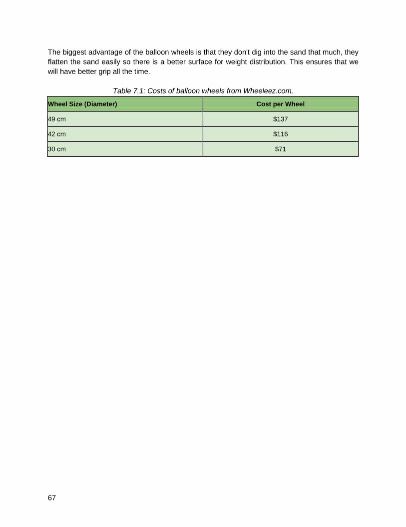
67
The biggest advantage of the balloon wheels is that they don't dig into the sand that much, they
flatten the sand easily so there is a better surface for weight distribution. This ensures that we
will have better grip all the time.
Table 7.1: Costs of balloon wheels from Wheeleez.com.
Wheel Size (Diameter) Cost per Wheel
49 cm $137
42 cm $116
30 cm $71
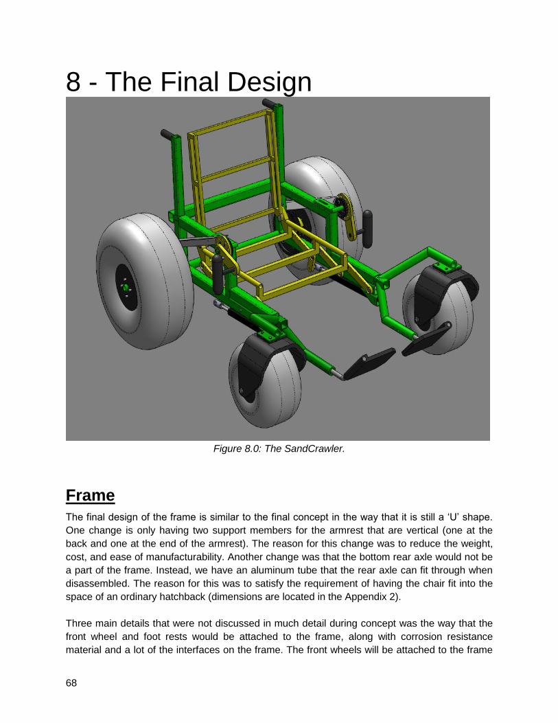
68
8 - The Final Design
Figure 8.0: The SandCrawler.
Frame
The final design of the frame is similar to the final concept in the way that it is still a ‘U’ shape.
One change is only having two support members for the armrest that are vertical (one at the
back and one at the end of the armrest). The reason for this change was to reduce the weight,
cost, and ease of manufacturability. Another change was that the bottom rear axle would not be
a part of the frame. Instead, we have an aluminum tube that the rear axle can fit through when
disassembled. The reason for this was to satisfy the requirement of having the chair fit into the
space of an ordinary hatchback (dimensions are located in the Appendix 2).
Three main details that were not discussed in much detail during concept was the way that the
front wheel and foot rests would be attached to the frame, along with corrosion resistance
material and a lot of the interfaces on the frame. The front wheels will be attached to the frame
69
via a separate assembly that slides into a square telescoping tube that is welded onto the top of
the bottom frame. Once the inner square tubing of the front wheel assembly is in the outer
square tubing, two pins will be inserted into the telescoping assembly so that they are fixed
together. We decided on two pins to reduce the amount of vibration and stress that would occur
with only one. The front wheel assembly will be a ‘Y’ shape with two cylindrical members
coming off the square telescoping tube. One will be for a welded plate so that the front wheel
casters can be screwed onto the assembly. The other cylindrical tubing will be for the footrests.
The cylindrical tubing size will be designed around the telescoping footrest that will be bought.
Figure 8.2 shows the actual footrest that will be purchased. Once the footrest is purchased, the
outer tube will be taken off so that the footrest will fit directly into the designed tubing that is
shown on Figure 8.3 without the holes drilled in for adjustment.
The frame will be submerged a lot in salt-water, so some corrosion resistance will be necessary
for this design to last. First off, drainage holes will be drilled into the back-bottom of the frame so
that no water stays in the frame and it will be easier to rinse off after use. The other preventative
measure for corrosion will be using an aluminum alloy that has some corrosion resistant
properties.
Construction
The main frame is constructed primarily of 38mm square tube aluminum with a wall thickness of
3.125mm with 1 pipe for the rear axle and 2 smaller 20mm square tubes. First, all members will
be mitered and machined and prepped for welding. We will then weld the frame together using a
TIG process, while being careful not to make the Heat Affected Zone too large with excess
currents. Each weld will first be spot welded on all sides as well as held in a jig to ensure
minimal warping.
After welding, the frame will be ground smooth and all burrs, sharp edges, and points removed.
Time and budget permitting, the frame will be powder coated at a local facility or on campus if
possible. The estimated time to manufacture the frame will be 48 hours
Because so many subcomponents are attached to the frame, interfaces are a very important
part of the frame design. The following is a list of the interface names and their description.
● Hand Crank:
Attached to top corner of armrest by welding the crankshaft
● Piston:
Attached to rear linkages and connection point at the front of the frame
● Pulley:
Front pulley attached to hand crank, rear pulleys attached at bottom back corners of frame and
will rotate freely
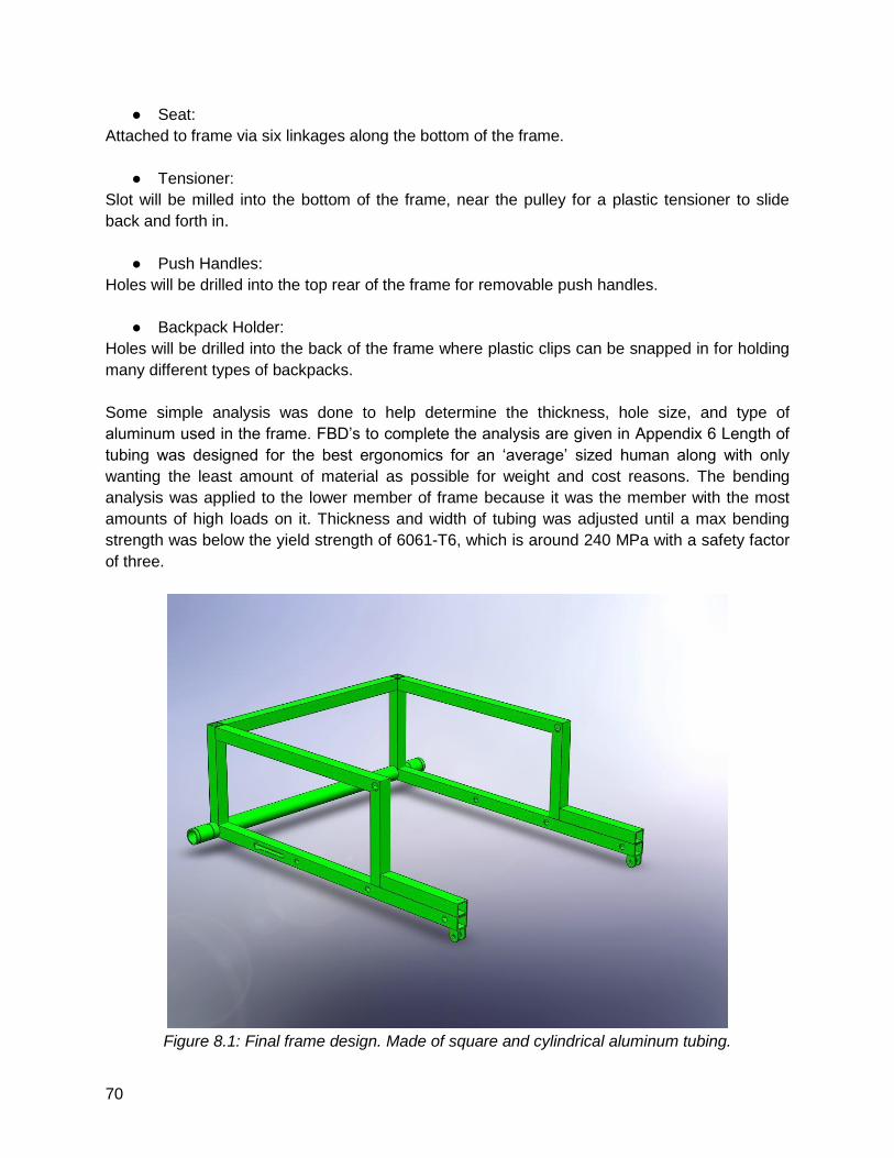
70
● Seat:
Attached to frame via six linkages along the bottom of the frame.
● Tensioner:
Slot will be milled into the bottom of the frame, near the pulley for a plastic tensioner to slide
back and forth in.
● Push Handles:
Holes will be drilled into the top rear of the frame for removable push handles.
● Backpack Holder:
Holes will be drilled into the back of the frame where plastic clips can be snapped in for holding
many different types of backpacks.
Some simple analysis was done to help determine the thickness, hole size, and type of
aluminum used in the frame. FBD’s to complete the analysis are given in Appendix 6 Length of
tubing was designed for the best ergonomics for an ‘average’ sized human along with only
wanting the least amount of material as possible for weight and cost reasons. The bending
analysis was applied to the lower member of frame because it was the member with the most
amounts of high loads on it. Thickness and width of tubing was adjusted until a max bending
strength was below the yield strength of 6061-T6, which is around 240 MPa with a safety factor
of three.
Figure 8.1: Final frame design. Made of square and cylindrical aluminum tubing.
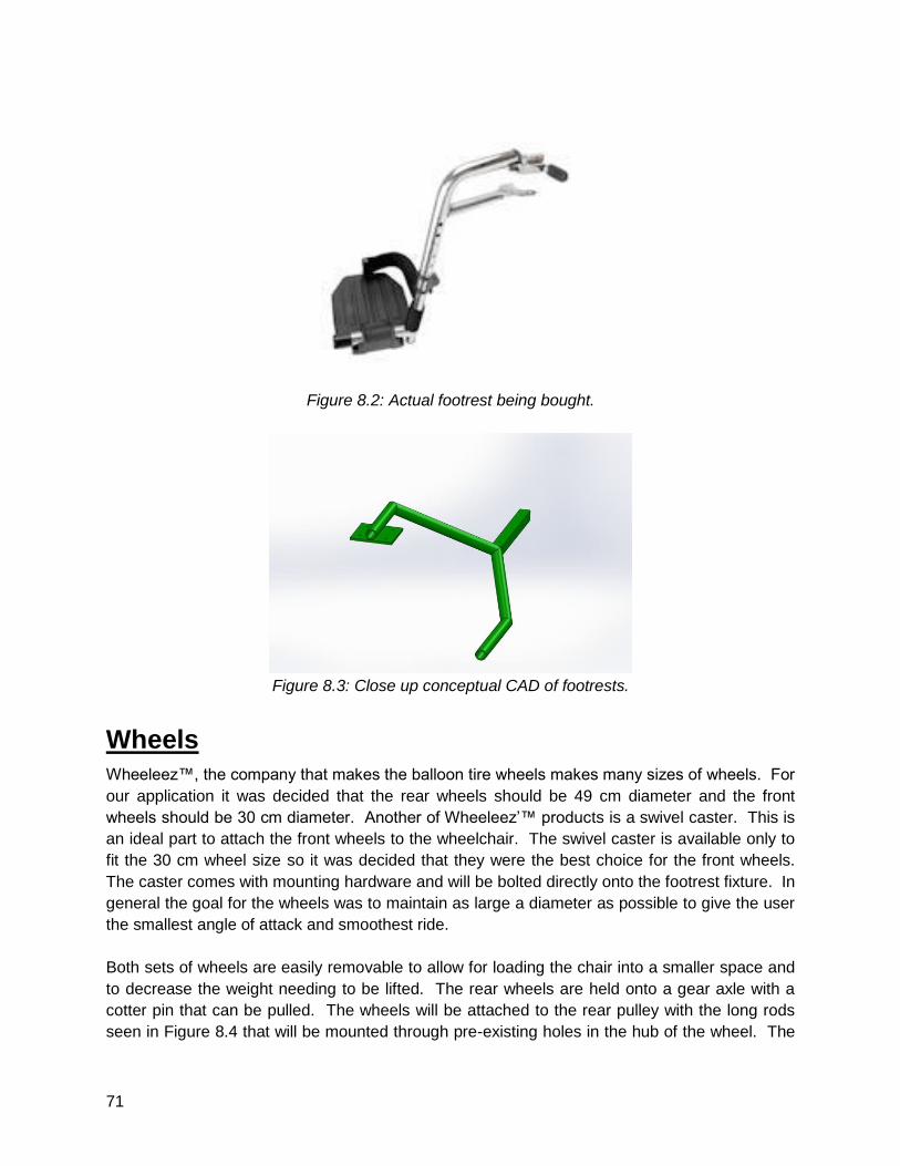
71
Figure 8.2: Actual footrest being bought.
Figure 8.3: Close up conceptual CAD of footrests.
Wheels
Wheeleez™, the company that makes the balloon tire wheels makes many sizes of wheels. For
our application it was decided that the rear wheels should be 49 cm diameter and the front
wheels should be 30 cm diameter. Another of Wheeleez’™ products is a swivel caster. This is
an ideal part to attach the front wheels to the wheelchair. The swivel caster is available only to
fit the 30 cm wheel size so it was decided that they were the best choice for the front wheels.
The caster comes with mounting hardware and will be bolted directly onto the footrest fixture. In
general the goal for the wheels was to maintain as large a diameter as possible to give the user
the smallest angle of attack and smoothest ride.
Both sets of wheels are easily removable to allow for loading the chair into a smaller space and
to decrease the weight needing to be lifted. The rear wheels are held onto a gear axle with a
cotter pin that can be pulled. The wheels will be attached to the rear pulley with the long rods
seen in Figure 8.4 that will be mounted through pre-existing holes in the hub of the wheel. The
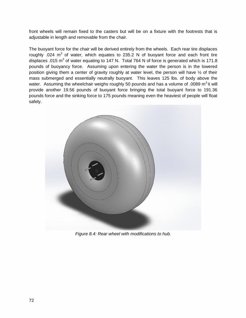
72
front wheels will remain fixed to the casters but will be on a fixture with the footrests that is
adjustable in length and removable from the chair.
The buoyant force for the chair will be derived entirely from the wheels. Each rear tire displaces
roughly .024 m3 of water, which equates to 235.2 N of buoyant force and each front tire
displaces .015 m3 of water equating to 147 N. Total 764 N of force is generated which is 171.8
pounds of buoyancy force. Assuming upon entering the water the person is in the lowered
position giving them a center of gravity roughly at water level, the person will have ½ of their
mass submerged and essentially neutrally buoyant. This leaves 125 lbs. of body above the
water. Assuming the wheelchair weighs roughly 50 pounds and has a volume of .0089 m3 it will
provide another 19.56 pounds of buoyant force bringing the total buoyant force to 191.36
pounds force and the sinking force to 175 pounds meaning even the heaviest of people will float
safely.
Figure 8.4: Rear wheel with modifications to hub.
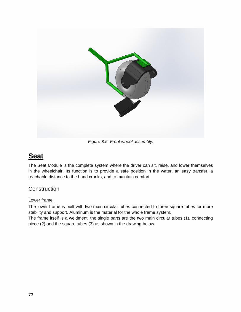
73
Figure 8.5: Front wheel assembly.
Seat
The Seat Module is the complete system where the driver can sit, raise, and lower themselves
in the wheelchair. Its function is to provide a safe position in the water, an easy transfer, a
reachable distance to the hand cranks, and to maintain comfort.
Construction
Lower frame
The lower frame is built with two main circular tubes connected to three square tubes for more
stability and support. Aluminum is the material for the whole frame system.
The frame itself is a weldment, the single parts are the two main circular tubes (1), connecting
piece (2) and the square tubes (3) as shown in the drawing below.
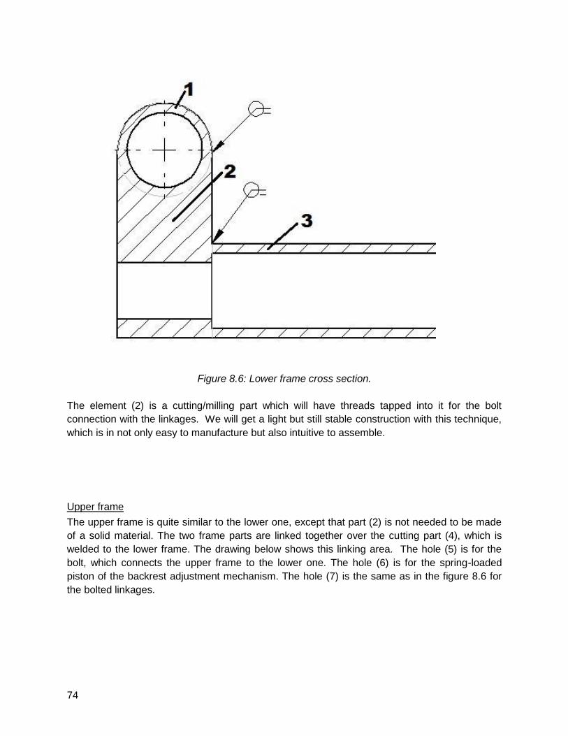
74
Figure 8.6: Lower frame cross section.
The element (2) is a cutting/milling part which will have threads tapped into it for the bolt
connection with the linkages. We will get a light but still stable construction with this technique,
which is in not only easy to manufacture but also intuitive to assemble.
Upper frame
The upper frame is quite similar to the lower one, except that part (2) is not needed to be made
of a solid material. The two frame parts are linked together over the cutting part (4), which is
welded to the lower frame. The drawing below shows this linking area. The hole (5) is for the
bolt, which connects the upper frame to the lower one. The hole (6) is for the spring-loaded
piston of the backrest adjustment mechanism. The hole (7) is the same as in the figure 8.6 for
the bolted linkages.
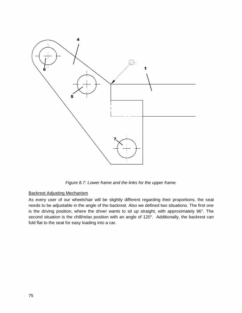
75
Figure 8.7: Lower frame and the links for the upper frame.
Backrest Adjusting Mechanism
As every user of our wheelchair will be slightly different regarding their proportions, the seat
needs to be adjustable in the angle of the backrest. Also we defined two situations. The first one
is the driving position, where the driver wants to sit up straight, with approximately 96°. The
second situation is the chill/relax position with an angle of 120°. Additionally, the backrest can
fold flat to the seat for easy loading into a car.
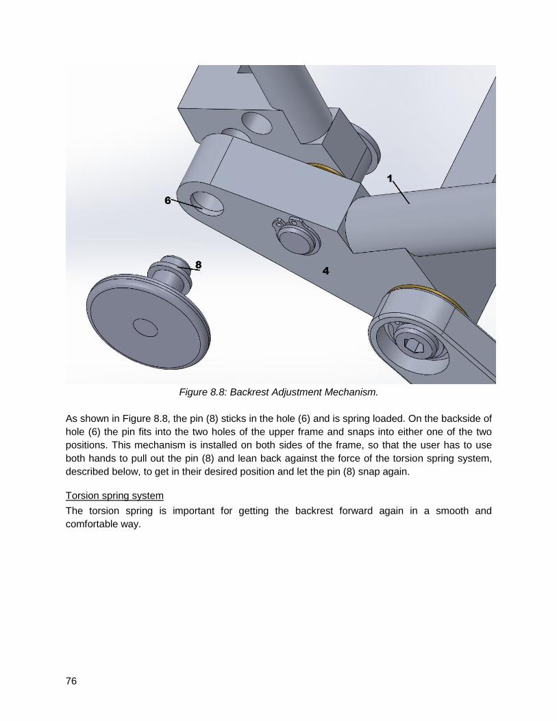
76
Figure 8.8: Backrest Adjustment Mechanism.
As shown in Figure 8.8, the pin (8) sticks in the hole (6) and is spring loaded. On the backside of
hole (6) the pin fits into the two holes of the upper frame and snaps into either one of the two
positions. This mechanism is installed on both sides of the frame, so that the user has to use
both hands to pull out the pin (8) and lean back against the force of the torsion spring system,
described below, to get in their desired position and let the pin (8) snap again.
Torsion spring system
The torsion spring is important for getting the backrest forward again in a smooth and
comfortable way.
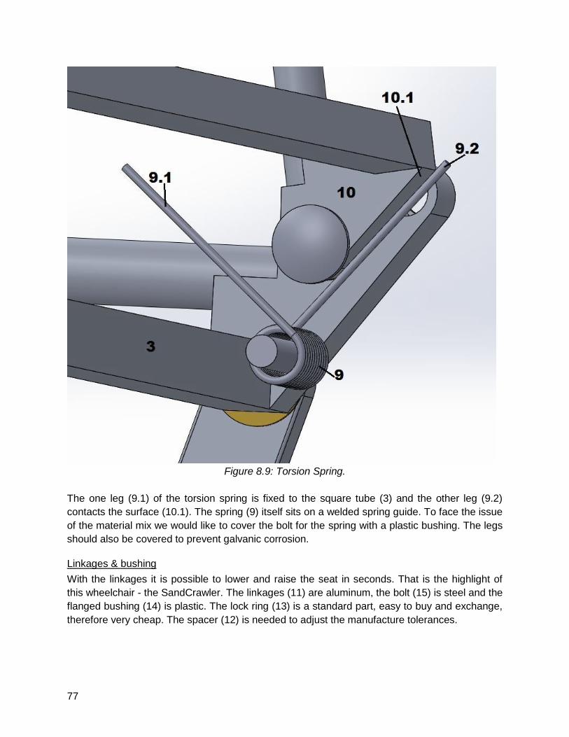
77
Figure 8.9: Torsion Spring.
The one leg (9.1) of the torsion spring is fixed to the square tube (3) and the other leg (9.2)
contacts the surface (10.1). The spring (9) itself sits on a welded spring guide. To face the issue
of the material mix we would like to cover the bolt for the spring with a plastic bushing. The legs
should also be covered to prevent galvanic corrosion.
Linkages & bushing
With the linkages it is possible to lower and raise the seat in seconds. That is the highlight of
this wheelchair - the SandCrawler. The linkages (11) are aluminum, the bolt (15) is steel and the
flanged bushing (14) is plastic. The lock ring (13) is a standard part, easy to buy and exchange,
therefore very cheap. The spacer (12) is needed to adjust the manufacture tolerances.
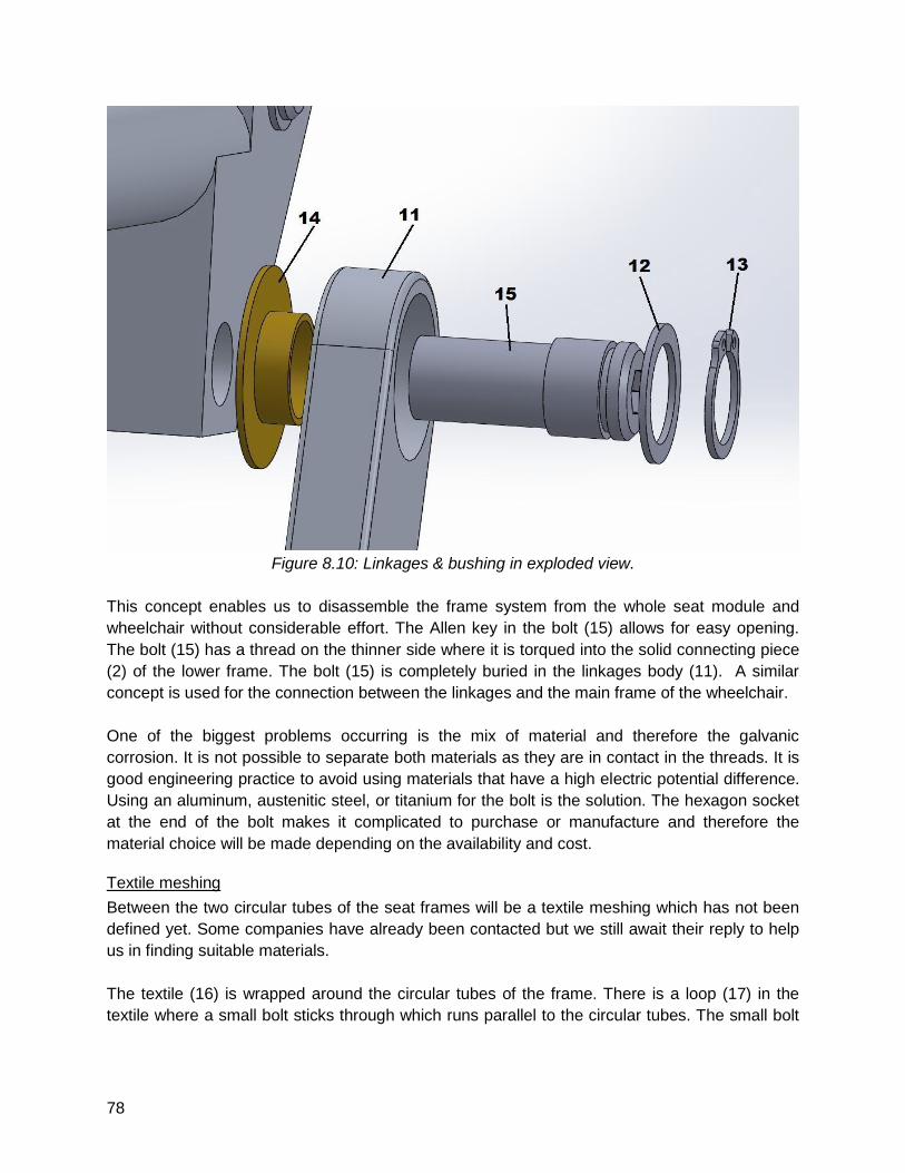
78
Figure 8.10: Linkages & bushing in exploded view.
This concept enables us to disassemble the frame system from the whole seat module and
wheelchair without considerable effort. The Allen key in the bolt (15) allows for easy opening.
The bolt (15) has a thread on the thinner side where it is torqued into the solid connecting piece
(2) of the lower frame. The bolt (15) is completely buried in the linkages body (11). A similar
concept is used for the connection between the linkages and the main frame of the wheelchair.
One of the biggest problems occurring is the mix of material and therefore the galvanic
corrosion. It is not possible to separate both materials as they are in contact in the threads. It is
good engineering practice to avoid using materials that have a high electric potential difference.
Using an aluminum, austenitic steel, or titanium for the bolt is the solution. The hexagon socket
at the end of the bolt makes it complicated to purchase or manufacture and therefore the
material choice will be made depending on the availability and cost.
Textile meshing
Between the two circular tubes of the seat frames will be a textile meshing which has not been
defined yet. Some companies have already been contacted but we still await their reply to help
us in finding suitable materials.
The textile (16) is wrapped around the circular tubes of the frame. There is a loop (17) in the
textile where a small bolt sticks through which runs parallel to the circular tubes. The small bolt
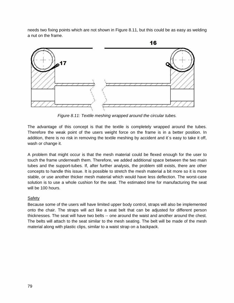
79
needs two fixing points which are not shown in Figure 8.11, but this could be as easy as welding
a nut on the frame.
Figure 8.11: Textile meshing wrapped around the circular tubes.
The advantage of this concept is that the textile is completely wrapped around the tubes.
Therefore the weak point of the users weight force on the frame is in a better position. In
addition, there is no risk in removing the textile meshing by accident and it´s easy to take it off,
wash or change it.
A problem that might occur is that the mesh material could be flexed enough for the user to
touch the frame underneath them. Therefore, we added additional space between the two main
tubes and the support-tubes. If, after further analysis, the problem still exists, there are other
concepts to handle this issue. It is possible to stretch the mesh material a bit more so it is more
stable, or use another thicker mesh material which would have less deflection. The worst-case
solution is to use a whole cushion for the seat. The estimated time for manufacturing the seat
will be 100 hours.
Safety
Because some of the users will have limited upper body control, straps will also be implemented
onto the chair. The straps will act like a seat belt that can be adjusted for different person
thicknesses. The seat will have two belts -- one around the waist and another around the chest.
The belts will attach to the seat similar to the mesh seating. The belt will be made of the mesh
material along with plastic clips, similar to a waist strap on a backpack.
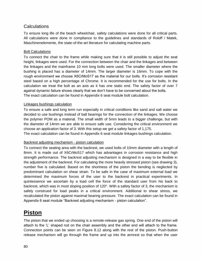
80
Calculations
To ensure long life of the beach wheelchair, safety calculations were done for all critical parts.
All calculations were done in compliance to the guidelines and standards of Roloff / Matek,
Maschinenelemente, the state-of-the-art literature for calculating machine parts.
Bolt Calculations
To connect the chair to the frame while making sure that it is still possible to adjust the seat
height, linkages were used. For the connection between the chair and the linkages and between
the linkages and the mainframe 10 mm long bolts were used. The smaller diameter where the
bushing is placed has a diameter of 14mm. The larger diameter is 16mm. To cope with the
rough environment we choose X6CrMoS17 as the material for our bolts. It’s corrosion resistant
steel based on a high percentage of Chrome. It is recommended for the use for bolts. In the
calculation we treat the bolt as an axis as it has one static end. The safety factor of over 7
against dynamic failure shows clearly that we don’t have to be concerned about the bolts.
The exact calculation can be found in Appendix 6 seat module bolt calculation.
Linkages bushings calculation
To ensure a safe and long term run especially in critical conditions like sand and salt water we
decided to use bushings instead of ball bearings for the connection of the linkages. We choose
the polymer POM as a material. The small width of 5mm leads to a bigger challenge, but with
the diameter of 14mm we are able to ensure safe use. Considering the critical environment we
choose an application factor of 3. With this setup we get a safety factor of 1,175.
The exact calculation can be found in Appendix 6 seat module linkages bushings calculation.
Backrest adjusting mechanism - piston calculation
To connect the seating area with the backrest, we used bolts of 10mm diameter with a length of
8mm. It is made out of X6CrMoS17 which has advantages in corrosion resistance and high
strength performance. The backrest adjusting mechanism is designed in a way to be flexible in
the adjustment of the backrest. For calculating the more heavily stressed piston (see drawing 3),
number five is calculated. Based on the shortness of the piston the bending is neglected by
predominant calculation on shear strain. To be safe in the case of maximum external load we
determined the maximum forces of the user to the backrest in practical experiments. In
quintessence we ascertain by a load cell the force of the standard user from his back to
backrest, which was in most sloping position of 120°. With a safety factor of 3, the mechanism is
safely construed for load peaks in a critical environment. Additional to shear stress, we
recalculated the piston against maximal bearing pressure. The exact calculation can be found in
Appendix 6 seat module “Backrest adjusting mechanism - piston calculation”.
Piston
The piston that we ended up choosing is a remote-release gas spring. One end of the piston will
attach to the ‘L’ shaped rod on the chair assembly and the other end will attach to the frame.
Connection points can be seen on Figure 8.12 along with the rest of the piston. Push-button
release mechanism will go through the frame and up into the armrest so that when the user
81
pushes off the seat, they can also push down on the button to activate the piston. The piston
has a 20 lbf pushing force, which is more than enough for the chair alone. From research that
was done on other pistons, the holding force would be well above the 900N needed for
maximum carrying capacity.
Figure 8.12: Piston Assembly along with hydraulic line and push button.
Hand Crank
Components
The hand crank is a power transfer system that allows the user to move the wheelchair using
their arm strength in a less taxing way than using the conventional wheel rim. As can be seen
in figure 8.13, it consists of a vertical handgrip that is connected to an aluminum crank. The
crank rotates freely on an aluminum shaft that will be welded to external side of the frame’s
armrest. Also connected to this shaft, is a metal disk (the pin disk see figure 8.13), which
attaches directly to the smaller Gates Carbon Drive Pulley. The pulley attaches to the pin disk
via bolts that run through the holes on the sides of the pulley and the corresponding holes on
the pin disk.
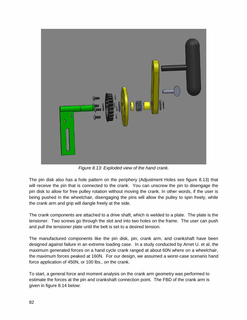
82
Figure 8.13: Exploded view of the hand crank.
The pin disk also has a hole pattern on the periphery (Adjustment Holes see figure 8.13) that
will receive the pin that is connected to the crank. You can unscrew the pin to disengage the
pin disk to allow for free pulley rotation without moving the crank. In other words, if the user is
being pushed in the wheelchair, disengaging the pins will allow the pulley to spin freely, while
the crank arm and grip will dangle freely at the side.
The crank components are attached to a drive shaft, which is welded to a plate. The plate is the
tensioner. Two screws go through the slot and into two holes on the frame. The user can push
and pull the tensioner plate until the belt is set to a desired tension.
The manufactured components like the pin disk, pin, crank arm, and crankshaft have been
designed against failure in an extreme loading case. In a study conducted by Arnet U. et al, the
maximum generated forces on a hand cycle crank ranged at about 60N where on a wheelchair,
the maximum forces peaked at 160N. For our design, we assumed a worst-case scenario hand
force application of 450N, or 100 lbs., on the crank.
To start, a general force and moment analysis on the crank arm geometry was performed to
estimate the forces at the pin and crankshaft connection point. The FBD of the crank arm is
given in figure 8.14 below:
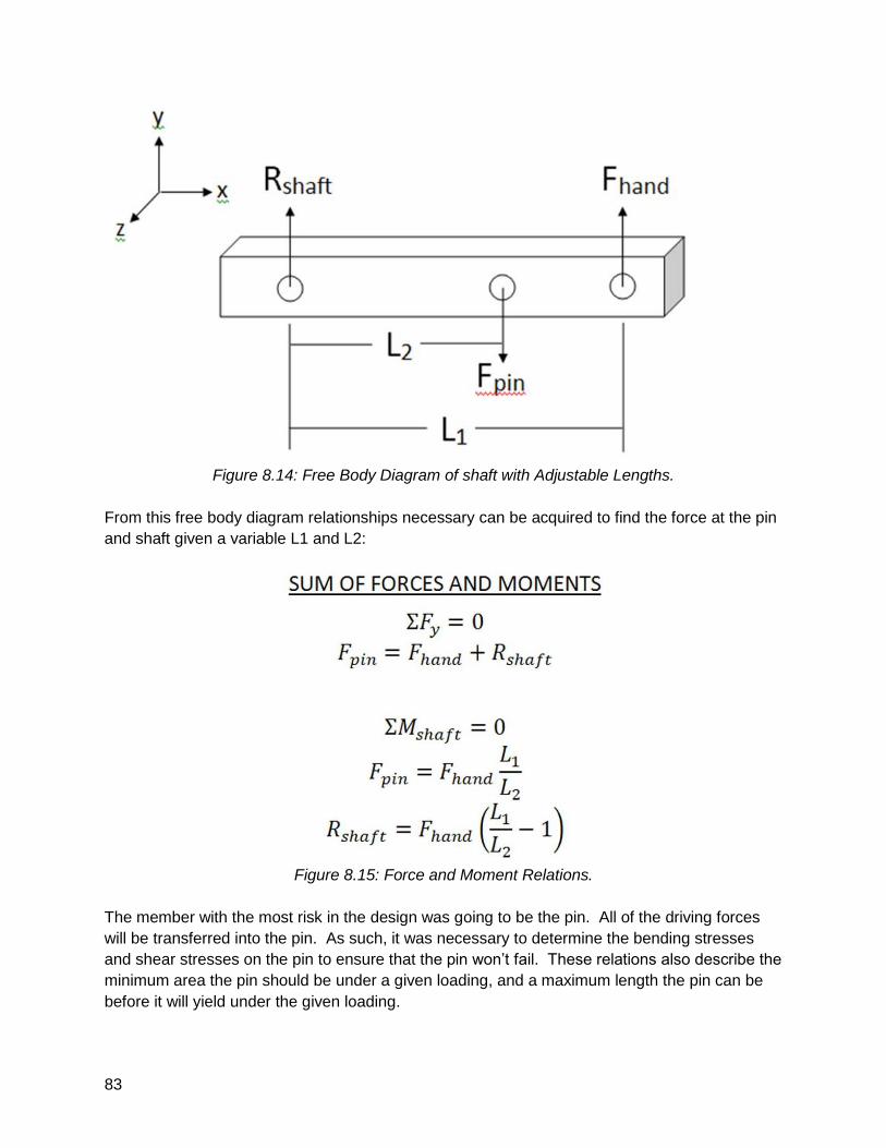
83
Figure 8.14: Free Body Diagram of shaft with Adjustable Lengths.
From this free body diagram relationships necessary can be acquired to find the force at the pin
and shaft given a variable L1 and L2:
Figure 8.15: Force and Moment Relations.
The member with the most risk in the design was going to be the pin. All of the driving forces
will be transferred into the pin. As such, it was necessary to determine the bending stresses
and shear stresses on the pin to ensure that the pin won’t fail. These relations also describe the
minimum area the pin should be under a given loading, and a maximum length the pin can be
before it will yield under the given loading.
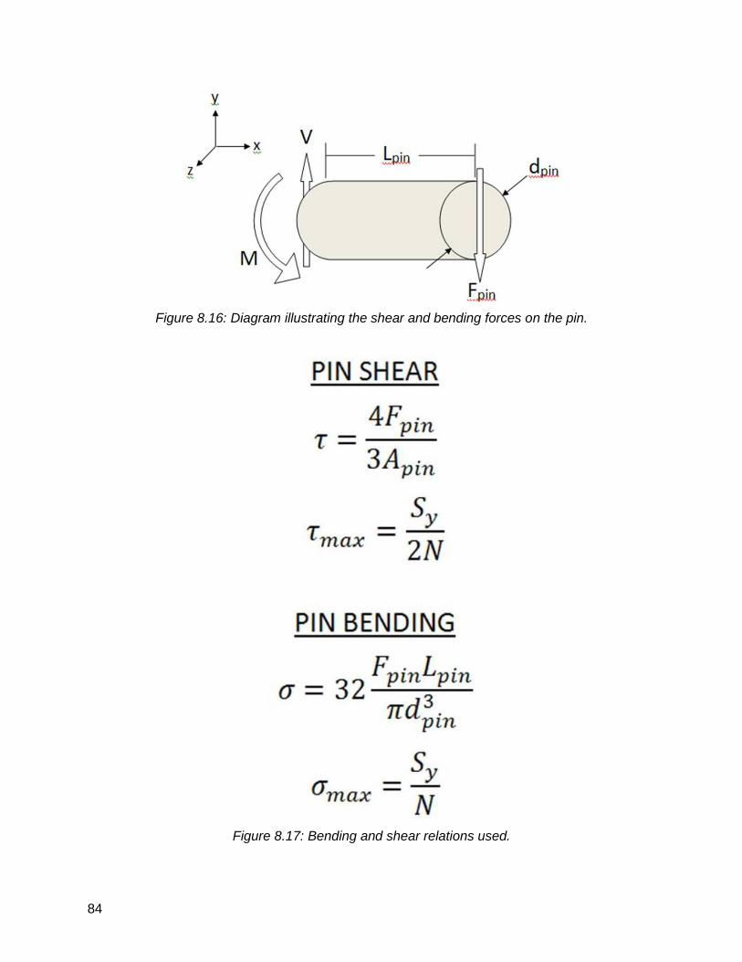
84
Figure 8.16: Diagram illustrating the shear and bending forces on the pin.
Figure 8.17: Bending and shear relations used.
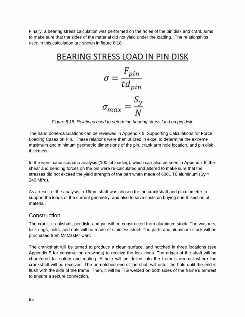
85
Finally, a bearing stress calculation was performed on the holes of the pin disk and crank arms
to make sure that the sides of the material did not yield under the loading. The relationships
used in this calculation are shown in figure 8.18:
Figure 8.18: Relations used to determine bearing stress load on pin disk.
The hand done-calculations can be reviewed in Appendix 6, Supporting Calculations for Force
Loading Cases on Pin. These relations were then utilized in excel to determine the extreme
maximum and minimum geometric dimensions of the pin, crank arm hole location, and pin disk
thickness.
In the worst case scenario analysis (100 lbf loading), which can also be seen in Appendix 6, the
shear and bending forces on the pin were re-calculated and altered to make sure that the
stresses did not exceed the yield strength of the part when made of 6061 T6 aluminum (Sy =
240 MPa).
As a result of the analysis, a 16mm shaft was chosen for the crankshaft and pin diameter to
support the loads of the current geometry, and also to save costs on buying one 6’ section of
material.
Construction
The crank, crankshaft, pin disk, and pin will be constructed from aluminum stock. The washers,
lock rings, bolts, and nuts will be made of stainless steel. The parts and aluminum stock will be
purchased from McMaster Carr.
The crankshaft will be turned to produce a clean surface, and notched in three locations (see
Appendix 5 for construction drawings) to receive the lock rings. The edges of the shaft will be
chamfered for safety and mating. A hole will be drilled into the frame’s armrest where the
crankshaft will be received. The un-notched end of the shaft will enter the hole until the end is
flush with the side of the frame. Then, it will be TIG welded on both sides of the frame’s armrest
to ensure a secure connection.
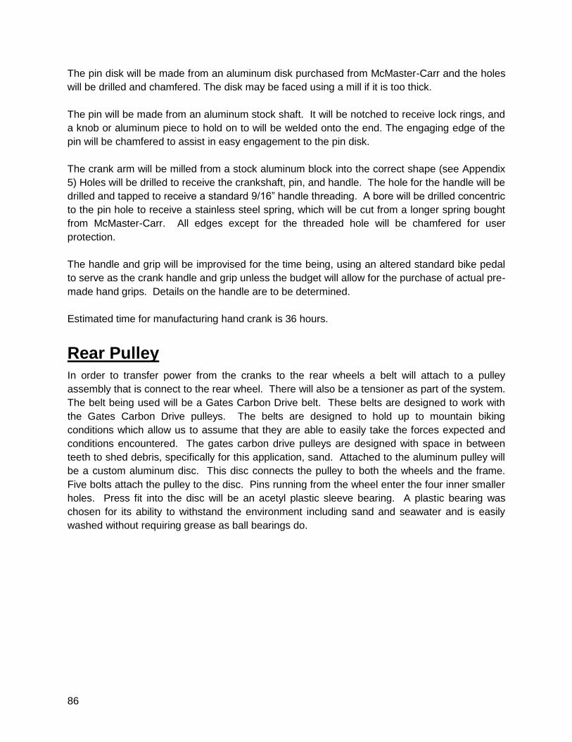
86
The pin disk will be made from an aluminum disk purchased from McMaster-Carr and the holes
will be drilled and chamfered. The disk may be faced using a mill if it is too thick.
The pin will be made from an aluminum stock shaft. It will be notched to receive lock rings, and
a knob or aluminum piece to hold on to will be welded onto the end. The engaging edge of the
pin will be chamfered to assist in easy engagement to the pin disk.
The crank arm will be milled from a stock aluminum block into the correct shape (see Appendix
5) Holes will be drilled to receive the crankshaft, pin, and handle. The hole for the handle will be
drilled and tapped to receive a standard 9/16” handle threading. A bore will be drilled concentric
to the pin hole to receive a stainless steel spring, which will be cut from a longer spring bought
from McMaster-Carr. All edges except for the threaded hole will be chamfered for user
protection.
The handle and grip will be improvised for the time being, using an altered standard bike pedal
to serve as the crank handle and grip unless the budget will allow for the purchase of actual pre-
made hand grips. Details on the handle are to be determined.
Estimated time for manufacturing hand crank is 36 hours.
Rear Pulley
In order to transfer power from the cranks to the rear wheels a belt will attach to a pulley
assembly that is connect to the rear wheel. There will also be a tensioner as part of the system.
The belt being used will be a Gates Carbon Drive belt. These belts are designed to work with
the Gates Carbon Drive pulleys. The belts are designed to hold up to mountain biking
conditions which allow us to assume that they are able to easily take the forces expected and
conditions encountered. The gates carbon drive pulleys are designed with space in between
teeth to shed debris, specifically for this application, sand. Attached to the aluminum pulley will
be a custom aluminum disc. This disc connects the pulley to both the wheels and the frame.
Five bolts attach the pulley to the disc. Pins running from the wheel enter the four inner smaller
holes. Press fit into the disc will be an acetyl plastic sleeve bearing. A plastic bearing was
chosen for its ability to withstand the environment including sand and seawater and is easily
washed without requiring grease as ball bearings do.
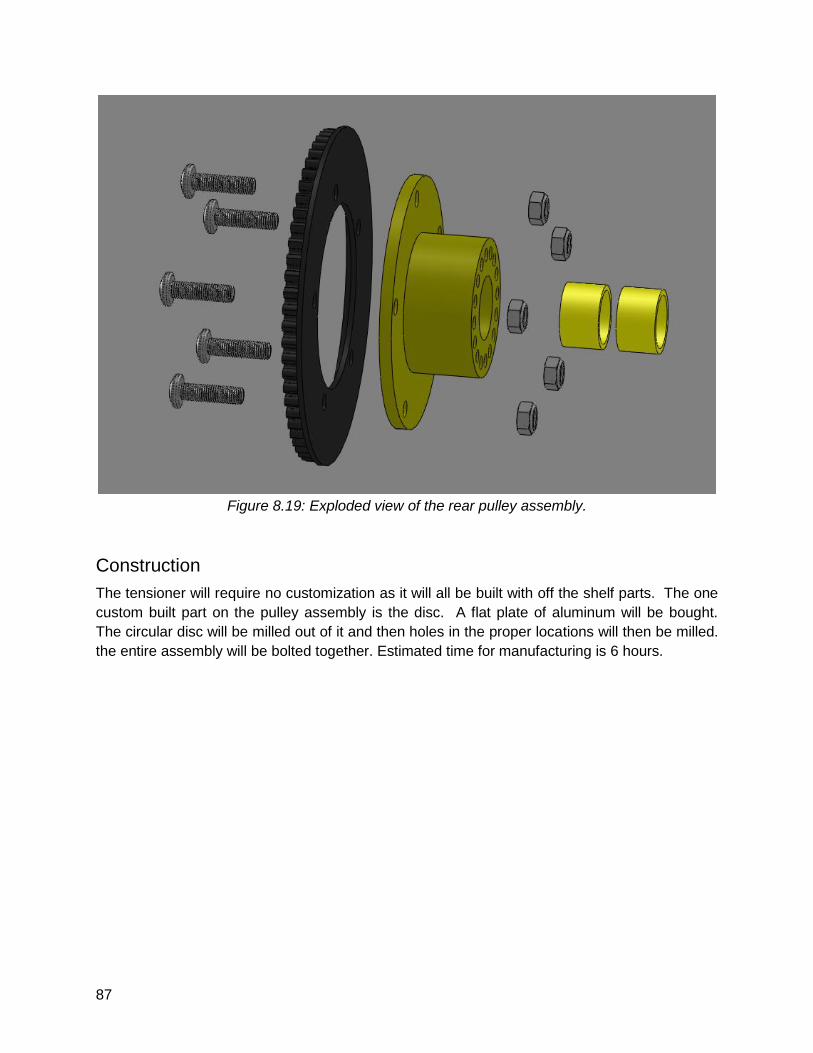
87
Figure 8.19: Exploded view of the rear pulley assembly.
Construction
The tensioner will require no customization as it will all be built with off the shelf parts. The one
custom built part on the pulley assembly is the disc. A flat plate of aluminum will be bought.
The circular disc will be milled out of it and then holes in the proper locations will then be milled.
the entire assembly will be bolted together. Estimated time for manufacturing is 6 hours.
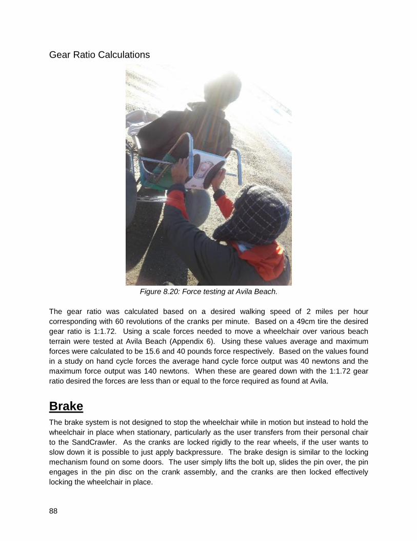
88
Gear Ratio Calculations
Figure 8.20: Force testing at Avila Beach.
The gear ratio was calculated based on a desired walking speed of 2 miles per hour
corresponding with 60 revolutions of the cranks per minute. Based on a 49cm tire the desired
gear ratio is 1:1.72. Using a scale forces needed to move a wheelchair over various beach
terrain were tested at Avila Beach (Appendix 6). Using these values average and maximum
forces were calculated to be 15.6 and 40 pounds force respectively. Based on the values found
in a study on hand cycle forces the average hand cycle force output was 40 newtons and the
maximum force output was 140 newtons. When these are geared down with the 1:1.72 gear
ratio desired the forces are less than or equal to the force required as found at Avila.
Brake
The brake system is not designed to stop the wheelchair while in motion but instead to hold the
wheelchair in place when stationary, particularly as the user transfers from their personal chair
to the SandCrawler. As the cranks are locked rigidly to the rear wheels, if the user wants to
slow down it is possible to just apply backpressure. The brake design is similar to the locking
mechanism found on some doors. The user simply lifts the bolt up, slides the pin over, the pin
engages in the pin disc on the crank assembly, and the cranks are then locked effectively
locking the wheelchair in place.
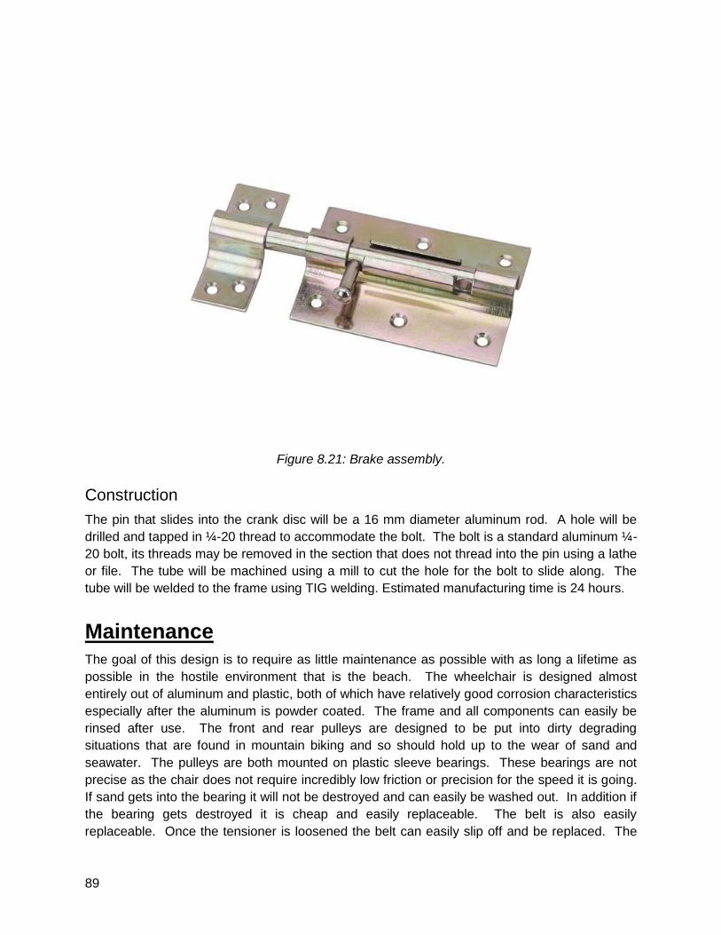
89
Figure 8.21: Brake assembly.
Construction
The pin that slides into the crank disc will be a 16 mm diameter aluminum rod. A hole will be
drilled and tapped in ¼-20 thread to accommodate the bolt. The bolt is a standard aluminum ¼-
20 bolt, its threads may be removed in the section that does not thread into the pin using a lathe
or file. The tube will be machined using a mill to cut the hole for the bolt to slide along. The
tube will be welded to the frame using TIG welding. Estimated manufacturing time is 24 hours.
Maintenance
The goal of this design is to require as little maintenance as possible with as long a lifetime as
possible in the hostile environment that is the beach. The wheelchair is designed almost
entirely out of aluminum and plastic, both of which have relatively good corrosion characteristics
especially after the aluminum is powder coated. The frame and all components can easily be
rinsed after use. The front and rear pulleys are designed to be put into dirty degrading
situations that are found in mountain biking and so should hold up to the wear of sand and
seawater. The pulleys are both mounted on plastic sleeve bearings. These bearings are not
precise as the chair does not require incredibly low friction or precision for the speed it is going.
If sand gets into the bearing it will not be destroyed and can easily be washed out. In addition if
the bearing gets destroyed it is cheap and easily replaceable. The belt is also easily
replaceable. Once the tensioner is loosened the belt can easily slip off and be replaced. The
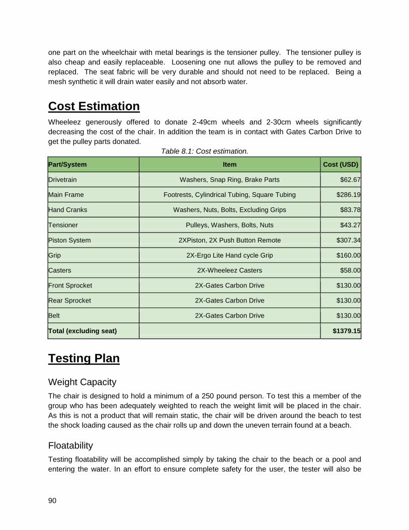
90
one part on the wheelchair with metal bearings is the tensioner pulley. The tensioner pulley is
also cheap and easily replaceable. Loosening one nut allows the pulley to be removed and
replaced. The seat fabric will be very durable and should not need to be replaced. Being a
mesh synthetic it will drain water easily and not absorb water.
Cost Estimation
Wheeleez generously offered to donate 2-49cm wheels and 2-30cm wheels significantly
decreasing the cost of the chair. In addition the team is in contact with Gates Carbon Drive to
get the pulley parts donated.
Table 8.1: Cost estimation.
Part/System Item Cost (USD)
Drivetrain Washers, Snap Ring, Brake Parts $62.67
Main Frame Footrests, Cylindrical Tubing, Square Tubing $286.19
Hand Cranks Washers, Nuts, Bolts, Excluding Grips $83.78
Tensioner Pulleys, Washers, Bolts, Nuts $43.27
Piston System 2XPiston, 2X Push Button Remote $307.34
Grip 2X-Ergo Lite Hand cycle Grip $160.00
Casters 2X-Wheeleez Casters $58.00
Front Sprocket 2X-Gates Carbon Drive $130.00
Rear Sprocket 2X-Gates Carbon Drive $130.00
Belt 2X-Gates Carbon Drive $130.00
Total (excluding seat) $1379.15
Testing Plan
Weight Capacity
The chair is designed to hold a minimum of a 250 pound person. To test this a member of the
group who has been adequately weighted to reach the weight limit will be placed in the chair.
As this is not a product that will remain static, the chair will be driven around the beach to test
the shock loading caused as the chair rolls up and down the uneven terrain found at a beach.
Floatability
Testing floatability will be accomplished simply by taking the chair to the beach or a pool and
entering the water. In an effort to ensure complete safety for the user, the tester will also be
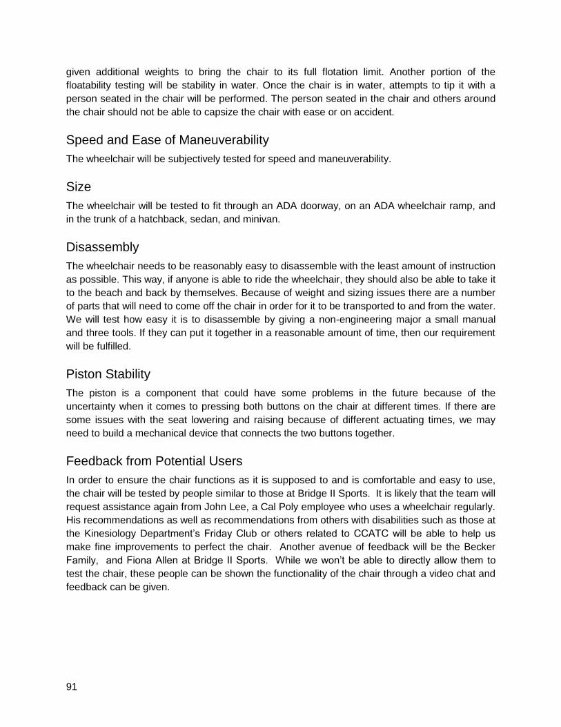
91
given additional weights to bring the chair to its full flotation limit. Another portion of the
floatability testing will be stability in water. Once the chair is in water, attempts to tip it with a
person seated in the chair will be performed. The person seated in the chair and others around
the chair should not be able to capsize the chair with ease or on accident.
Speed and Ease of Maneuverability
The wheelchair will be subjectively tested for speed and maneuverability.
Size
The wheelchair will be tested to fit through an ADA doorway, on an ADA wheelchair ramp, and
in the trunk of a hatchback, sedan, and minivan.
Disassembly
The wheelchair needs to be reasonably easy to disassemble with the least amount of instruction
as possible. This way, if anyone is able to ride the wheelchair, they should also be able to take it
to the beach and back by themselves. Because of weight and sizing issues there are a number
of parts that will need to come off the chair in order for it to be transported to and from the water.
We will test how easy it is to disassemble by giving a non-engineering major a small manual
and three tools. If they can put it together in a reasonable amount of time, then our requirement
will be fulfilled.
Piston Stability
The piston is a component that could have some problems in the future because of the
uncertainty when it comes to pressing both buttons on the chair at different times. If there are
some issues with the seat lowering and raising because of different actuating times, we may
need to build a mechanical device that connects the two buttons together.
Feedback from Potential Users
In order to ensure the chair functions as it is supposed to and is comfortable and easy to use,
the chair will be tested by people similar to those at Bridge II Sports. It is likely that the team will
request assistance again from John Lee, a Cal Poly employee who uses a wheelchair regularly.
His recommendations as well as recommendations from others with disabilities such as those at
the Kinesiology Department’s Friday Club or others related to CCATC will be able to help us
make fine improvements to perfect the chair. Another avenue of feedback will be the Becker
Family, and Fiona Allen at Bridge II Sports. While we won’t be able to directly allow them to
test the chair, these people can be shown the functionality of the chair through a video chat and
feedback can be given.
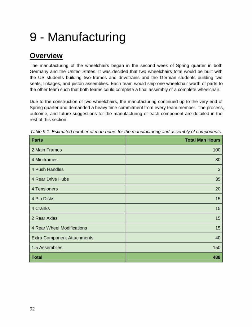
92
9 - Manufacturing
Overview
The manufacturing of the wheelchairs began in the second week of Spring quarter in both
Germany and the United States. It was decided that two wheelchairs total would be built with
the US students building two frames and drivetrains and the German students building two
seats, linkages, and piston assemblies. Each team would ship one wheelchair worth of parts to
the other team such that both teams could complete a final assembly of a complete wheelchair.
Due to the construction of two wheelchairs, the manufacturing continued up to the very end of
Spring quarter and demanded a heavy time commitment from every team member. The process,
outcome, and future suggestions for the manufacturing of each component are detailed in the
rest of this section.
Table 9.1: Estimated number of man-hours for the manufacturing and assembly of components.
Parts Total Man Hours
2 Main Frames 100
4 Miniframes 80
4 Push Handles 3
4 Rear Drive Hubs 35
4 Tensioners 20
4 Pin Disks 15
4 Cranks 15
2 Rear Axles 15
4 Rear Wheel Modifications 15
Extra Component Attachments 40
1.5 Assemblies 150
Total 488
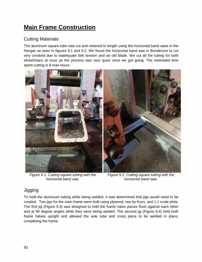
93
Main Frame Construction
Cutting Materials
The aluminum square tube was cut and metered to length using the horizontal band saws in the
Hangar as seen in figures 9.1 and 9.2. We found the horizontal band saw in Bonderson to cut
very crooked due to inadequate belt tension and an old blade. We cut all the tubing for both
wheelchairs at once as the process was very quick once we got going. The estimated time
spent cutting is 8 man-hours.
Figure 9.1: Cutting square tubing with the
horizontal band saw.
Figure 9.2: Cutting square tubing with the
horizontal band saw.
Jigging
To hold the aluminum tubing while being welded, it was determined that jigs would need to be
created. Two jigs for the main frame were built using plywood, two by fours, and 1:1 scale plots.
The first jig (Figure 9.3) was designed to hold the frame halve pieces flush against each other
and at 90 degree angles while they were being welded. The second jig (Figure 9.4) held both
frame halves upright and allowed the axle tube and cross piece to be welded in place,
completing the frame.
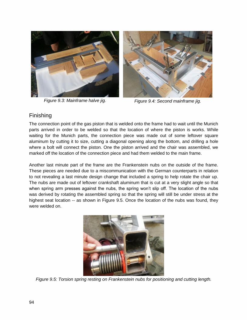
94
Figure 9.3: Mainframe halve jig.
Figure 9.4: Second mainframe jig.
Finishing
The connection point of the gas piston that is welded onto the frame had to wait until the Munich
parts arrived in order to be welded so that the location of where the piston is works. While
waiting for the Munich parts, the connection piece was made out of some leftover square
aluminum by cutting it to size, cutting a diagonal opening along the bottom, and drilling a hole
where a bolt will connect the piston. One the piston arrived and the chair was assembled, we
marked off the location of the connection piece and had them welded to the main frame.
Another last minute part of the frame are the Frankenstein nubs on the outside of the frame.
These pieces are needed due to a miscommunication with the German counterparts in relation
to not revealing a last minute design change that included a spring to help rotate the chair up.
The nubs are made out of leftover crankshaft aluminum that is cut at a very slight angle so that
when spring arm presses against the nubs, the spring won’t slip off. The location of the nubs
was derived by rotating the assembled spring so that the spring will still be under stress at the
highest seat location -- as shown in Figure 9.5. Once the location of the nubs was found, they
were welded on.
Figure 9.5: Torsion spring resting on Frankenstein nubs for positioning and cutting length.
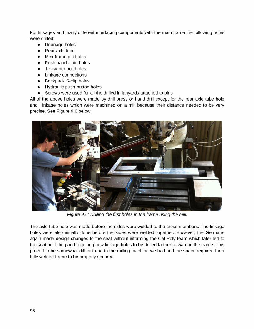
95
For linkages and many different interfacing components with the main frame the following holes
were drilled:
● Drainage holes
● Rear axle tube
● Mini-frame pin holes
● Push handle pin holes
● Tensioner bolt holes
● Linkage connections
● Backpack S-clip holes
● Hydraulic push-button holes
● Screws were used for all the drilled in lanyards attached to pins
All of the above holes were made by drill press or hand drill except for the rear axle tube hole
and linkage holes which were machined on a mill because their distance needed to be very
precise. See Figure 9.6 below.
Figure 9.6: Drilling the first holes in the frame using the mill.
The axle tube hole was made before the sides were welded to the cross members. The linkage
holes were also initially done before the sides were welded together. However, the Germans
again made design changes to the seat without informing the Cal Poly team which later led to
the seat not fitting and requiring new linkage holes to be drilled farther forward in the frame. This
proved to be somewhat difficult due to the milling machine we had and the space required for a
fully welded frame to be properly secured.
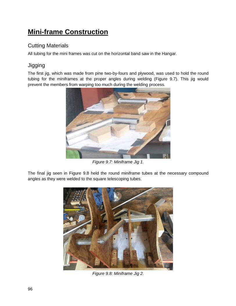
96
Mini-frame Construction
Cutting Materials
All tubing for the mini frames was cut on the horizontal band saw in the Hangar.
Jigging
The first jig, which was made from pine two-by-fours and plywood, was used to hold the round
tubing for the miniframes at the proper angles during welding (Figure 9.7). This jig would
prevent the members from warping too much during the welding process.
Figure 9.7: Miniframe Jig 1.
The final jig seen in Figure 9.8 held the round miniframe tubes at the necessary compound
angles as they were welded to the square telescoping tubes.
Figure 9.8: Miniframe Jig 2.

97
Finish Work
For all the welding, a belt sander was used on the circular tubing. To connect the round tubing
together, the connecting ends of each tube were grinded down at a 45-degree angle so that the
weld could penetrate through the wall of the aluminum since the tubing was too thick. To
connect the square tubing to the round tubing in Jig 2, sanding was done on the round tube so
that it would rest flush against the square tubing.
The last piece of the mini-frame to be welded was the caster plate to the end of the outer round
tube so that the plastic caster that was donated by WeeleezTM could bolt on. For the frame that
was sent to Munich, the aluminum plate was directly welded to the round tube with a little bit of
sanding along the area of the round tubing that the plate was going to be attached. After the
frame was assembled, it was found that the casters interfered with the mini-frame by a
millimeter or two when turning. Because the frame was already anodized, time had run out, and
the wheelchair could still function at this point, we decided to keep this flaw on chair one, but fix
chair two (the chair assembled at Cal Poly). We ended up increasing the distance between the
caster and the mini-frame by taking some rectangular bar stock, cutting it to size with a
horizontal band saw and rounding out one side so that it was flush against the round tubing and
the caster plate. This not only created the distance we wanted but made it easier to weld
everything together. The machining of these spacer blocks is seen in Figure 9.9 below.
Figure 9.9: Caster mounting plate offset block.
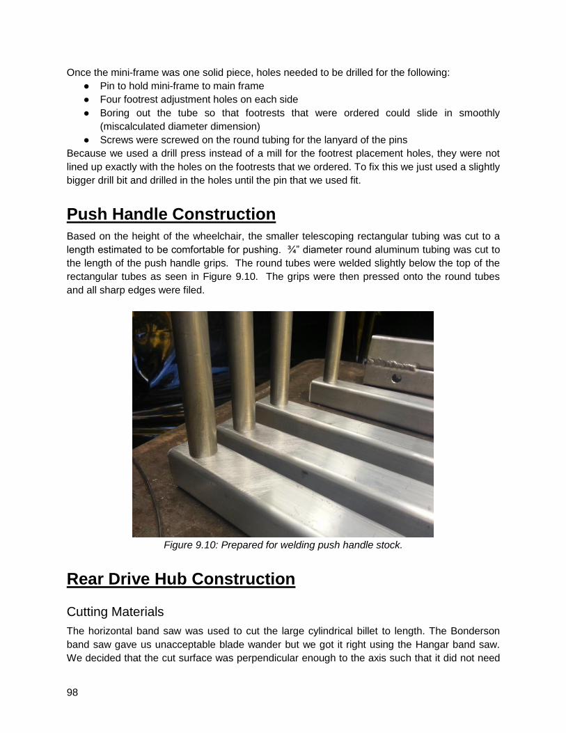
98
Once the mini-frame was one solid piece, holes needed to be drilled for the following:
● Pin to hold mini-frame to main frame
● Four footrest adjustment holes on each side
● Boring out the tube so that footrests that were ordered could slide in smoothly
(miscalculated diameter dimension)
● Screws were screwed on the round tubing for the lanyard of the pins
Because we used a drill press instead of a mill for the footrest placement holes, they were not
lined up exactly with the holes on the footrests that we ordered. To fix this we just used a slightly
bigger drill bit and drilled in the holes until the pin that we used fit.
Push Handle Construction
Based on the height of the wheelchair, the smaller telescoping rectangular tubing was cut to a
length estimated to be comfortable for pushing. ¾” diameter round aluminum tubing was cut to
the length of the push handle grips. The round tubes were welded slightly below the top of the
rectangular tubes as seen in Figure 9.10. The grips were then pressed onto the round tubes
and all sharp edges were filed.
Figure 9.10: Prepared for welding push handle stock.
Rear Drive Hub Construction
Cutting Materials
The horizontal band saw was used to cut the large cylindrical billet to length. The Bonderson
band saw gave us unacceptable blade wander but we got it right using the Hangar band saw.
We decided that the cut surface was perpendicular enough to the axis such that it did not need
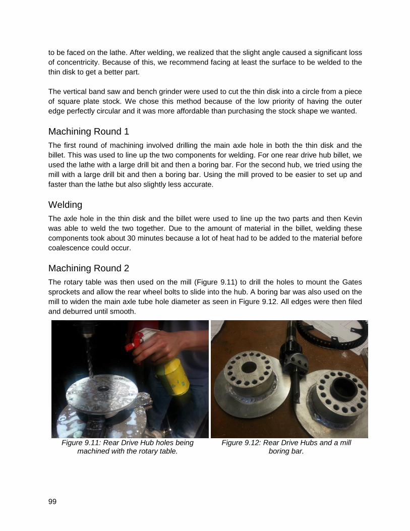
99
to be faced on the lathe. After welding, we realized that the slight angle caused a significant loss
of concentricity. Because of this, we recommend facing at least the surface to be welded to the
thin disk to get a better part.
The vertical band saw and bench grinder were used to cut the thin disk into a circle from a piece
of square plate stock. We chose this method because of the low priority of having the outer
edge perfectly circular and it was more affordable than purchasing the stock shape we wanted.
Machining Round 1
The first round of machining involved drilling the main axle hole in both the thin disk and the
billet. This was used to line up the two components for welding. For one rear drive hub billet, we
used the lathe with a large drill bit and then a boring bar. For the second hub, we tried using the
mill with a large drill bit and then a boring bar. Using the mill proved to be easier to set up and
faster than the lathe but also slightly less accurate.
Welding
The axle hole in the thin disk and the billet were used to line up the two parts and then Kevin
was able to weld the two together. Due to the amount of material in the billet, welding these
components took about 30 minutes because a lot of heat had to be added to the material before
coalescence could occur.
Machining Round 2
The rotary table was then used on the mill (Figure 9.11) to drill the holes to mount the Gates
sprockets and allow the rear wheel bolts to slide into the hub. A boring bar was also used on the
mill to widen the main axle tube hole diameter as seen in Figure 9.12. All edges were then filed
and deburred until smooth.
Figure 9.11: Rear Drive Hub holes being
machined with the rotary table.
Figure 9.12: Rear Drive Hubs and a mill
boring bar.
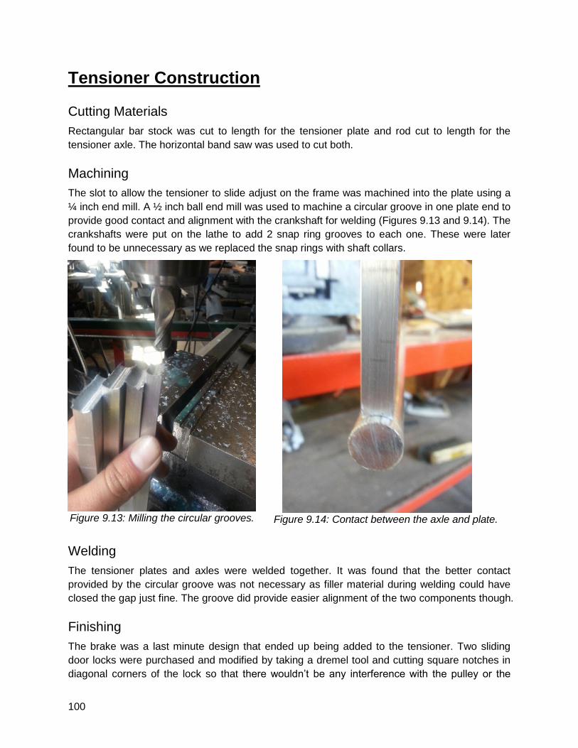
100
Tensioner Construction
Cutting Materials
Rectangular bar stock was cut to length for the tensioner plate and rod cut to length for the
tensioner axle. The horizontal band saw was used to cut both.
Machining
The slot to allow the tensioner to slide adjust on the frame was machined into the plate using a
¼ inch end mill. A ½ inch ball end mill was used to machine a circular groove in one plate end to
provide good contact and alignment with the crankshaft for welding (Figures 9.13 and 9.14). The
crankshafts were put on the lathe to add 2 snap ring grooves to each one. These were later
found to be unnecessary as we replaced the snap rings with shaft collars.
Figure 9.13: Milling the circular grooves.
Figure 9.14: Contact between the axle and plate.
Welding
The tensioner plates and axles were welded together. It was found that the better contact
provided by the circular groove was not necessary as filler material during welding could have
closed the gap just fine. The groove did provide easier alignment of the two components though.
Finishing
The brake was a last minute design that ended up being added to the tensioner. Two sliding
door locks were purchased and modified by taking a dremel tool and cutting square notches in
diagonal corners of the lock so that there wouldn’t be any interference with the pulley or the
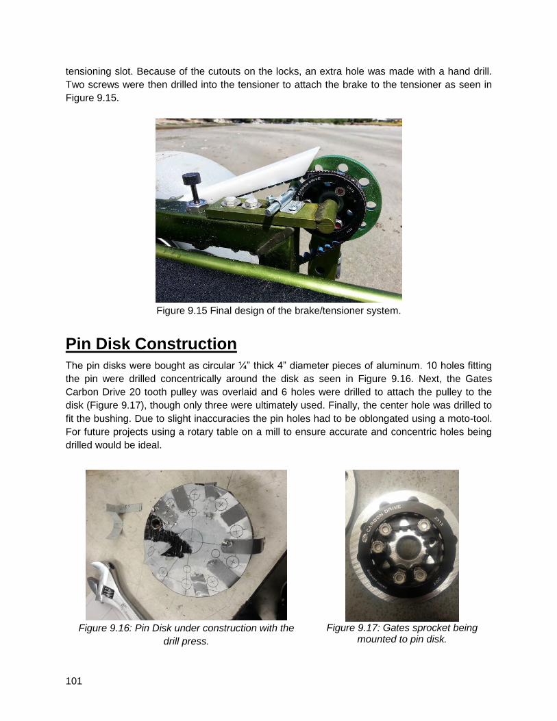
101
tensioning slot. Because of the cutouts on the locks, an extra hole was made with a hand drill.
Two screws were then drilled into the tensioner to attach the brake to the tensioner as seen in
Figure 9.15.
Figure 9.15 Final design of the brake/tensioner system.
Pin Disk Construction
The pin disks were bought as circular ¼” thick 4” diameter pieces of aluminum. 10 holes fitting
the pin were drilled concentrically around the disk as seen in Figure 9.16. Next, the Gates
Carbon Drive 20 tooth pulley was overlaid and 6 holes were drilled to attach the pulley to the
disk (Figure 9.17), though only three were ultimately used. Finally, the center hole was drilled to
fit the bushing. Due to slight inaccuracies the pin holes had to be oblongated using a moto-tool.
For future projects using a rotary table on a mill to ensure accurate and concentric holes being
drilled would be ideal.
Figure 9.16: Pin Disk under construction with the
drill press.
Figure 9.17: Gates sprocket being
mounted to pin disk.
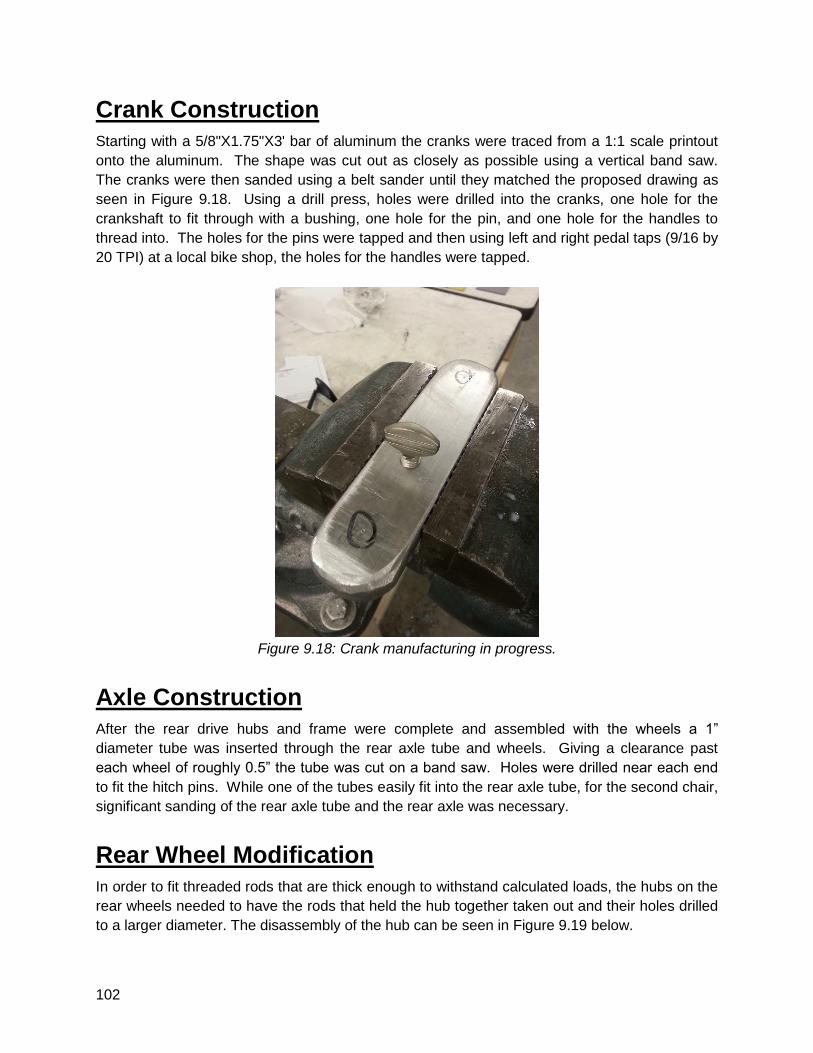
102
Crank Construction
Starting with a 5/8"X1.75"X3' bar of aluminum the cranks were traced from a 1:1 scale printout
onto the aluminum. The shape was cut out as closely as possible using a vertical band saw.
The cranks were then sanded using a belt sander until they matched the proposed drawing as
seen in Figure 9.18. Using a drill press, holes were drilled into the cranks, one hole for the
crankshaft to fit through with a bushing, one hole for the pin, and one hole for the handles to
thread into. The holes for the pins were tapped and then using left and right pedal taps (9/16 by
20 TPI) at a local bike shop, the holes for the handles were tapped.
Figure 9.18: Crank manufacturing in progress.
Axle Construction
After the rear drive hubs and frame were complete and assembled with the wheels a 1”
diameter tube was inserted through the rear axle tube and wheels. Giving a clearance past
each wheel of roughly 0.5” the tube was cut on a band saw. Holes were drilled near each end
to fit the hitch pins. While one of the tubes easily fit into the rear axle tube, for the second chair,
significant sanding of the rear axle tube and the rear axle was necessary.
Rear Wheel Modification
In order to fit threaded rods that are thick enough to withstand calculated loads, the hubs on the
rear wheels needed to have the rods that held the hub together taken out and their holes drilled
to a larger diameter. The disassembly of the hub can be seen in Figure 9.19 below.
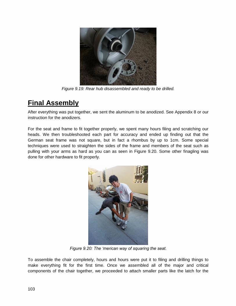
103
Figure 9.19: Rear hub disassembled and ready to be drilled.
Final Assembly
After everything was put together, we sent the aluminum to be anodized. See Appendix 8 or our
instruction for the anodizers.
For the seat and frame to fit together properly, we spent many hours filing and scratching our
heads. We then troubleshooted each part for accuracy and ended up finding out that the
German seat frame was not square, but in fact a rhombus by up to 1cm. Some special
techniques were used to straighten the sides of the frame and members of the seat such as
pulling with your arms as hard as you can as seen in Figure 9.20. Some other finagling was
done for other hardware to fit properly.
Figure 9.20: The ‘merican way of squaring the seat.
To assemble the chair completely, hours and hours were put it to filing and drilling things to
make everything fit for the first time. Once we assembled all of the major and critical
components of the chair together, we proceeded to attach smaller parts like the latch for the
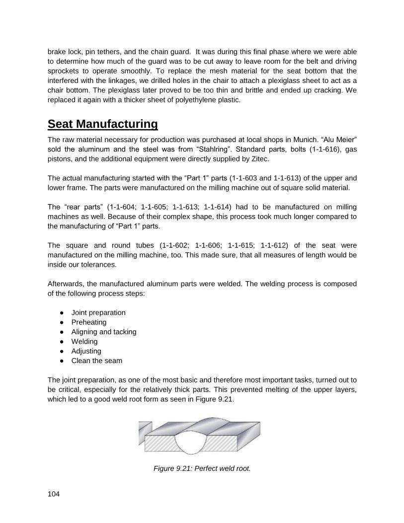
104
brake lock, pin tethers, and the chain guard. It was during this final phase where we were able
to determine how much of the guard was to be cut away to leave room for the belt and driving
sprockets to operate smoothly. To replace the mesh material for the seat bottom that the
interfered with the linkages, we drilled holes in the chair to attach a plexiglass sheet to act as a
chair bottom. The plexiglass later proved to be too thin and brittle and ended up cracking. We
replaced it again with a thicker sheet of polyethylene plastic.
Seat Manufacturing
The raw material necessary for production was purchased at local shops in Munich. “Alu Meier”
sold the aluminum and the steel was from “Stahlring”. Standard parts, bolts (1-1-616), gas
pistons, and the additional equipment were directly supplied by Zitec.
The actual manufacturing started with the “Part 1” parts (1-1-603 and 1-1-613) of the upper and
lower frame. The parts were manufactured on the milling machine out of square solid material.
The “rear parts” (1-1-604; 1-1-605; 1-1-613; 1-1-614) had to be manufactured on milling
machines as well. Because of their complex shape, this process took much longer compared to
the manufacturing of “Part 1” parts.
The square and round tubes (1-1-602; 1-1-606; 1-1-615; 1-1-612) of the seat were
manufactured on the milling machine, too. This made sure, that all measures of length would be
inside our tolerances.
Afterwards, the manufactured aluminum parts were welded. The welding process is composed
of the following process steps:
● Joint preparation
● Preheating
● Aligning and tacking
● Welding
● Adjusting
● Clean the seam
The joint preparation, as one of the most basic and therefore most important tasks, turned out to
be critical, especially for the relatively thick parts. This prevented melting of the upper layers,
which led to a good weld root form as seen in Figure 9.21.
Figure 9.21: Perfect weld root.
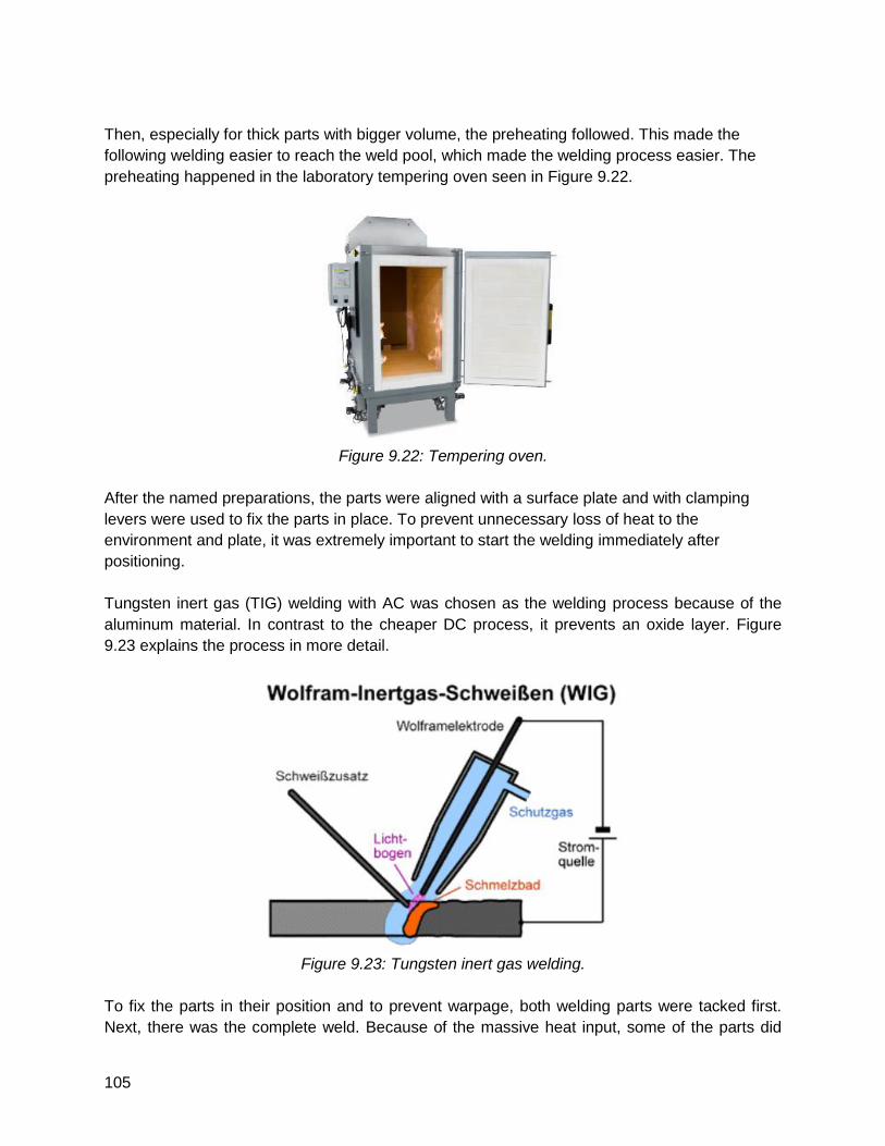
105
Then, especially for thick parts with bigger volume, the preheating followed. This made the
following welding easier to reach the weld pool, which made the welding process easier. The
preheating happened in the laboratory tempering oven seen in Figure 9.22.
Figure 9.22: Tempering oven.
After the named preparations, the parts were aligned with a surface plate and with clamping
levers were used to fix the parts in place. To prevent unnecessary loss of heat to the
environment and plate, it was extremely important to start the welding immediately after
positioning.
Tungsten inert gas (TIG) welding with AC was chosen as the welding process because of the
aluminum material. In contrast to the cheaper DC process, it prevents an oxide layer. Figure
9.23 explains the process in more detail.
Figure 9.23: Tungsten inert gas welding.
To fix the parts in their position and to prevent warpage, both welding parts were tacked first.
Next, there was the complete weld. Because of the massive heat input, some of the parts did
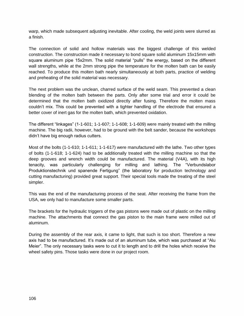
106
warp, which made subsequent adjusting inevitable. After cooling, the weld joints were slurred as
a finish.
The connection of solid and hollow materials was the biggest challenge of this welded
construction. The construction made it necessary to bond square solid aluminum 15x15mm with
square aluminum pipe 15x2mm. The solid material “pulls” the energy, based on the different
wall strengths, while at the 2mm strong pipe the temperature for the molten bath can be easily
reached. To produce this molten bath nearly simultaneously at both parts, practice of welding
and preheating of the solid material was necessary.
The next problem was the unclean, charred surface of the weld seam. This prevented a clean
blending of the molten bath between the parts. Only after some trial and error it could be
determined that the molten bath oxidized directly after fusing. Therefore the molten mass
couldn’t mix. This could be prevented with a tighter handling of the electrode that ensured a
better cover of inert gas for the molten bath, which prevented oxidation.
The different “linkages” (1-1-601; 1-1-607; 1-1-608; 1-1-609) were mainly treated with the milling
machine. The big radii, however, had to be ground with the belt sander, because the workshops
didn’t have big enough radius cutters.
Most of the bolts (1-1-610; 1-1-611; 1-1-617) were manufactured with the lathe. Two other types
of bolts (1-1-618; 1-1-624) had to be additionally treated with the milling machine so that the
deep grooves and wrench width could be manufactured. The material (V4A), with its high
tenacity, was particularly challenging for milling and lathing. The “Verbundslabor
Produktionstechnik und spanende Fertigung” (the laboratory for production technology and
cutting manufacturing) provided great support. Their special tools made the treating of the steel
simpler.
This was the end of the manufacturing process of the seat. After receiving the frame from the
USA, we only had to manufacture some smaller parts.
The brackets for the hydraulic triggers of the gas pistons were made out of plastic on the milling
machine. The attachments that connect the gas piston to the main frame were milled out of
aluminum.
During the assembly of the rear axis, it came to light, that such is too short. Therefore a new
axis had to be manufactured. It’s made out of an aluminum tube, which was purchased at “Alu
Meier”. The only necessary tasks were to cut it to length and to drill the holes which receive the
wheel safety pins. Those tasks were done in our project room.
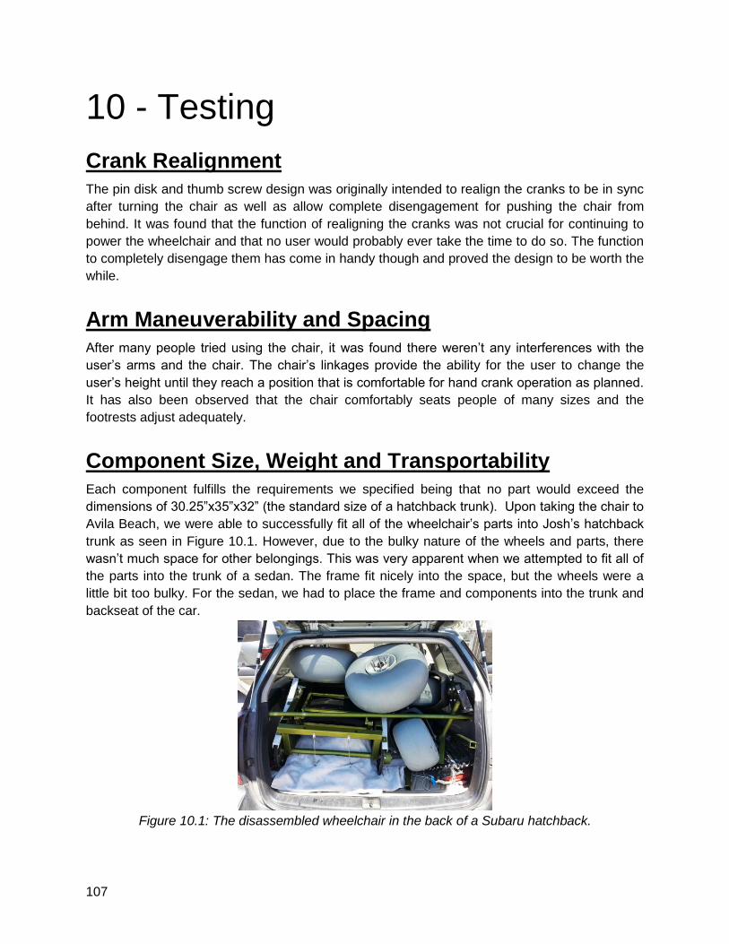
107
10 - Testing
Crank Realignment
The pin disk and thumb screw design was originally intended to realign the cranks to be in sync
after turning the chair as well as allow complete disengagement for pushing the chair from
behind. It was found that the function of realigning the cranks was not crucial for continuing to
power the wheelchair and that no user would probably ever take the time to do so. The function
to completely disengage them has come in handy though and proved the design to be worth the
while.
Arm Maneuverability and Spacing
After many people tried using the chair, it was found there weren’t any interferences with the
user’s arms and the chair. The chair’s linkages provide the ability for the user to change the
user’s height until they reach a position that is comfortable for hand crank operation as planned.
It has also been observed that the chair comfortably seats people of many sizes and the
footrests adjust adequately.
Component Size, Weight and Transportability
Each component fulfills the requirements we specified being that no part would exceed the
dimensions of 30.25”x35”x32” (the standard size of a hatchback trunk). Upon taking the chair to
Avila Beach, we were able to successfully fit all of the wheelchair’s parts into Josh’s hatchback
trunk as seen in Figure 10.1. However, due to the bulky nature of the wheels and parts, there
wasn’t much space for other belongings. This was very apparent when we attempted to fit all of
the parts into the trunk of a sedan. The frame fit nicely into the space, but the wheels were a
little bit too bulky. For the sedan, we had to place the frame and components into the trunk and
backseat of the car.
Figure 10.1: The disassembled wheelchair in the back of a Subaru hatchback.
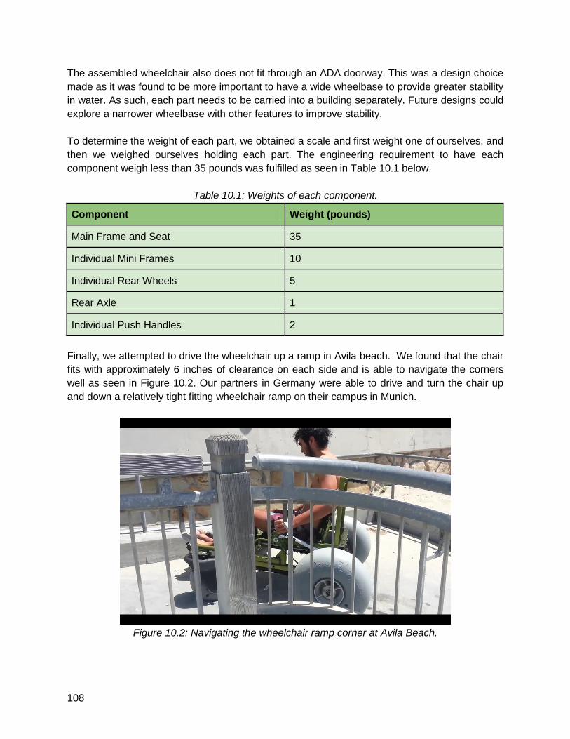
108
The assembled wheelchair also does not fit through an ADA doorway. This was a design choice
made as it was found to be more important to have a wide wheelbase to provide greater stability
in water. As such, each part needs to be carried into a building separately. Future designs could
explore a narrower wheelbase with other features to improve stability.
To determine the weight of each part, we obtained a scale and first weight one of ourselves, and
then we weighed ourselves holding each part. The engineering requirement to have each
component weigh less than 35 pounds was fulfilled as seen in Table 10.1 below.
Table 10.1: Weights of each component.
Component Weight (pounds)
Main Frame and Seat 35
Individual Mini Frames 10
Individual Rear Wheels 5
Rear Axle 1
Individual Push Handles 2
Finally, we attempted to drive the wheelchair up a ramp in Avila beach. We found that the chair
fits with approximately 6 inches of clearance on each side and is able to navigate the corners
well as seen in Figure 10.2. Our partners in Germany were able to drive and turn the chair up
and down a relatively tight fitting wheelchair ramp on their campus in Munich.
Figure 10.2: Navigating the wheelchair ramp corner at Avila Beach.
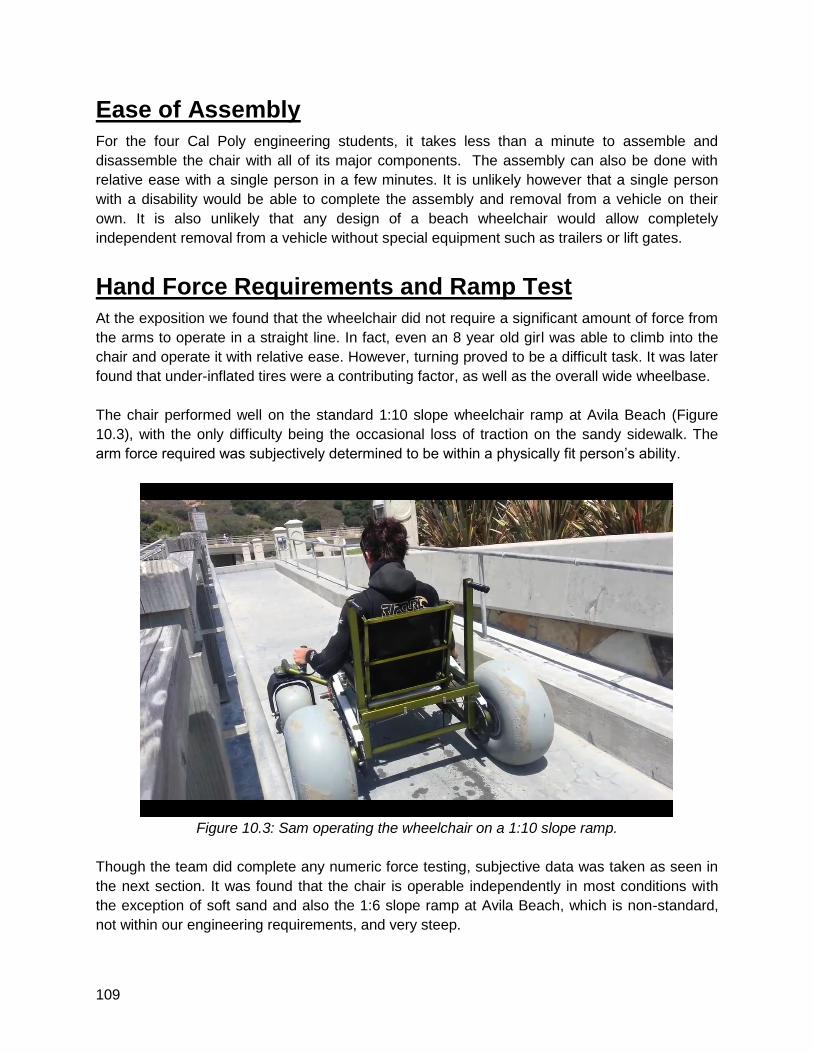
109
Ease of Assembly
For the four Cal Poly engineering students, it takes less than a minute to assemble and
disassemble the chair with all of its major components. The assembly can also be done with
relative ease with a single person in a few minutes. It is unlikely however that a single person
with a disability would be able to complete the assembly and removal from a vehicle on their
own. It is also unlikely that any design of a beach wheelchair would allow completely
independent removal from a vehicle without special equipment such as trailers or lift gates.
Hand Force Requirements and Ramp Test
At the exposition we found that the wheelchair did not require a significant amount of force from
the arms to operate in a straight line. In fact, even an 8 year old girl was able to climb into the
chair and operate it with relative ease. However, turning proved to be a difficult task. It was later
found that under-inflated tires were a contributing factor, as well as the overall wide wheelbase.
The chair performed well on the standard 1:10 slope wheelchair ramp at Avila Beach (Figure
10.3), with the only difficulty being the occasional loss of traction on the sandy sidewalk. The
arm force required was subjectively determined to be within a physically fit person’s ability.
Figure 10.3: Sam operating the wheelchair on a 1:10 slope ramp.
Though the team did complete any numeric force testing, subjective data was taken as seen in
the next section. It was found that the chair is operable independently in most conditions with
the exception of soft sand and also the 1:6 slope ramp at Avila Beach, which is non-standard,
not within our engineering requirements, and very steep.
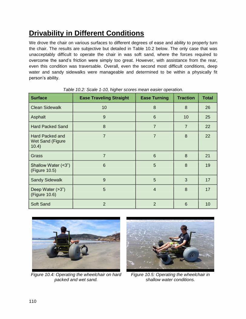
110
Drivability in Different Conditions
We drove the chair on various surfaces to different degrees of ease and ability to properly turn
the chair. The results are subjective but detailed in Table 10.2 below. The only case that was
unacceptably difficult to operate the chair in was soft sand, where the forces required to
overcome the sand’s friction were simply too great. However, with assistance from the rear,
even this condition was traversable. Overall, even the second most difficult conditions, deep
water and sandy sidewalks were manageable and determined to be within a physically fit
person’s ability.
Table 10.2: Scale 1-10, higher scores mean easier operation.
Surface Ease Traveling Straight Ease Turning Traction Total
Clean Sidewalk 10 8 8 26
Asphalt 9 6 10 25
Hard Packed Sand 8 7 7 22
Hard Packed and Wet Sand (Figure 10.4)
7 7 8 22
Grass 7 6 8 21
Shallow Water (<3”) (Figure 10.5)
6 5 8 19
Sandy Sidewalk 9 5 3 17
Deep Water (>3”) (Figure 10.6)
5 4 8 17
Soft Sand 2 2 6 10
Figure 10.4: Operating the wheelchair on hard
packed and wet sand.
Figure 10.5: Operating the wheelchair in
shallow water conditions.
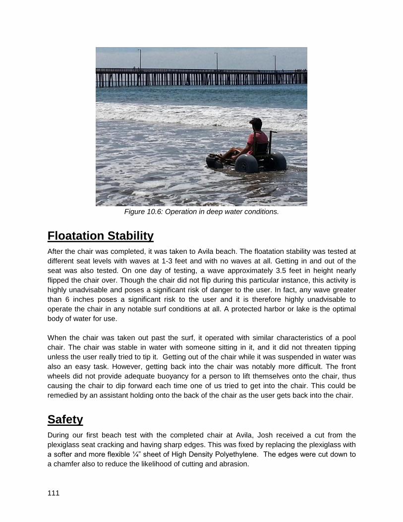
111
Figure 10.6: Operation in deep water conditions.
Floatation Stability
After the chair was completed, it was taken to Avila beach. The floatation stability was tested at
different seat levels with waves at 1-3 feet and with no waves at all. Getting in and out of the
seat was also tested. On one day of testing, a wave approximately 3.5 feet in height nearly
flipped the chair over. Though the chair did not flip during this particular instance, this activity is
highly unadvisable and poses a significant risk of danger to the user. In fact, any wave greater
than 6 inches poses a significant risk to the user and it is therefore highly unadvisable to
operate the chair in any notable surf conditions at all. A protected harbor or lake is the optimal
body of water for use.
When the chair was taken out past the surf, it operated with similar characteristics of a pool
chair. The chair was stable in water with someone sitting in it, and it did not threaten tipping
unless the user really tried to tip it. Getting out of the chair while it was suspended in water was
also an easy task. However, getting back into the chair was notably more difficult. The front
wheels did not provide adequate buoyancy for a person to lift themselves onto the chair, thus
causing the chair to dip forward each time one of us tried to get into the chair. This could be
remedied by an assistant holding onto the back of the chair as the user gets back into the chair.
Safety
During our first beach test with the completed chair at Avila, Josh received a cut from the
plexiglass seat cracking and having sharp edges. This was fixed by replacing the plexiglass with
a softer and more flexible ¼” sheet of High Density Polyethylene. The edges were cut down to
a chamfer also to reduce the likelihood of cutting and abrasion.
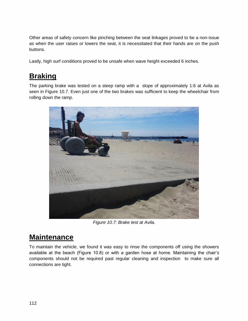
112
Other areas of safety concern like pinching between the seat linkages proved to be a non-issue
as when the user raises or lowers the seat, it is necessitated that their hands are on the push
buttons.
Lastly, high surf conditions proved to be unsafe when wave height exceeded 6 inches.
Braking
The parking brake was tested on a steep ramp with a slope of approximately 1:6 at Avila as
seen in Figure 10.7. Even just one of the two brakes was sufficient to keep the wheelchair from
rolling down the ramp.
Figure 10.7: Brake test at Avila.
Maintenance
To maintain the vehicle, we found it was easy to rinse the components off using the showers
available at the beach (Figure 10.8) or with a garden hose at home. Maintaining the chair’s
components should not be required past regular cleaning and inspection to make sure all
connections are tight.
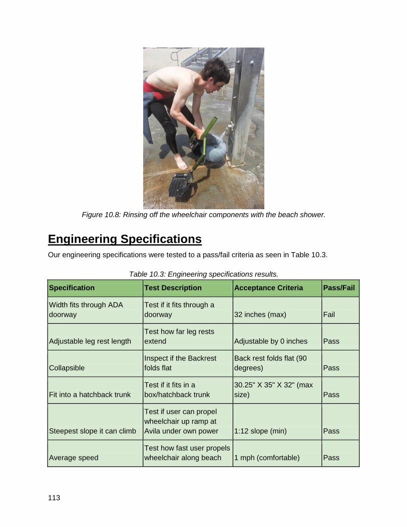
113
Figure 10.8: Rinsing off the wheelchair components with the beach shower.
Engineering Specifications
Our engineering specifications were tested to a pass/fail criteria as seen in Table 10.3.
Table 10.3: Engineering specifications results.
Specification Test Description Acceptance Criteria Pass/Fail
Width fits through ADA
doorway
Test if it fits through a
doorway 32 inches (max) Fail
Adjustable leg rest length
Test how far leg rests
extend Adjustable by 0 inches Pass
Collapsible
Inspect if the Backrest
folds flat
Back rest folds flat (90
degrees) Pass
Fit into a hatchback trunk
Test if it fits in a
box/hatchback trunk
30.25" X 35" X 32" (max
size) Pass
Steepest slope it can climb
Test if user can propel
wheelchair up ramp at
Avila under own power 1:12 slope (min) Pass
Average speed
Test how fast user propels
wheelchair along beach 1 mph (comfortable) Pass
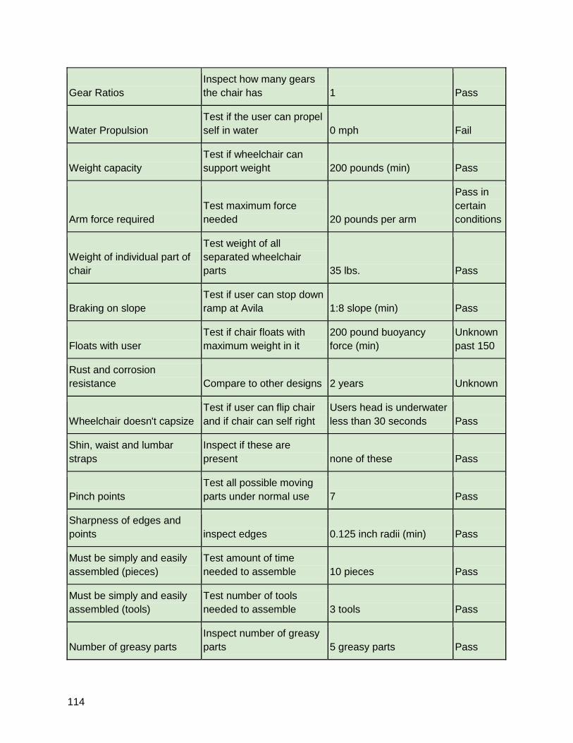
114
Gear Ratios
Inspect how many gears
the chair has 1 Pass
Water Propulsion
Test if the user can propel
self in water 0 mph Fail
Weight capacity
Test if wheelchair can
support weight 200 pounds (min) Pass
Arm force required
Test maximum force
needed 20 pounds per arm
Pass in
certain
conditions
Weight of individual part of
chair
Test weight of all
separated wheelchair
parts 35 lbs. Pass
Braking on slope
Test if user can stop down
ramp at Avila 1:8 slope (min) Pass
Floats with user
Test if chair floats with
maximum weight in it
200 pound buoyancy
force (min)
Unknown
past 150
Rust and corrosion
resistance Compare to other designs 2 years Unknown
Wheelchair doesn't capsize
Test if user can flip chair
and if chair can self right
Users head is underwater
less than 30 seconds Pass
Shin, waist and lumbar
straps
Inspect if these are
present none of these Pass
Pinch points
Test all possible moving
parts under normal use 7 Pass
Sharpness of edges and
points inspect edges 0.125 inch radii (min) Pass
Must be simply and easily
assembled (pieces)
Test amount of time
needed to assemble 10 pieces Pass
Must be simply and easily
assembled (tools)
Test number of tools
needed to assemble 3 tools Pass
Number of greasy parts
Inspect number of greasy
parts 5 greasy parts Pass
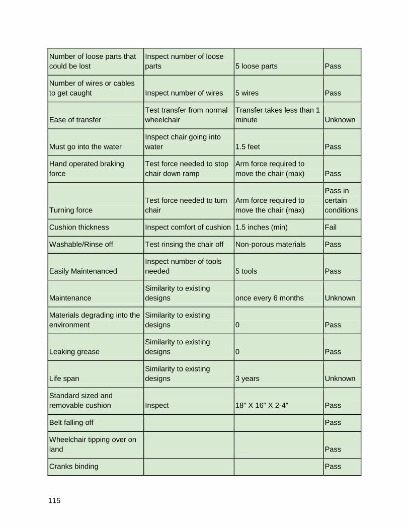
115
Number of loose parts that
could be lost
Inspect number of loose
parts 5 loose parts Pass
Number of wires or cables
to get caught Inspect number of wires 5 wires Pass
Ease of transfer
Test transfer from normal
wheelchair
Transfer takes less than 1
minute Unknown
Must go into the water
Inspect chair going into
water 1.5 feet Pass
Hand operated braking
force
Test force needed to stop
chair down ramp
Arm force required to
move the chair (max) Pass
Turning force
Test force needed to turn
chair
Arm force required to
move the chair (max)
Pass in
certain
conditions
Cushion thickness Inspect comfort of cushion 1.5 inches (min) Fail
Washable/Rinse off Test rinsing the chair off Non-porous materials Pass
Easily Maintenanced
Inspect number of tools
needed 5 tools Pass
Maintenance
Similarity to existing
designs once every 6 months Unknown
Materials degrading into the
environment
Similarity to existing
designs 0 Pass
Leaking grease
Similarity to existing
designs 0 Pass
Life span
Similarity to existing
designs 3 years Unknown
Standard sized and
removable cushion Inspect 18" X 16" X 2-4" Pass
Belt falling off Pass
Wheelchair tipping over on
land Pass
Cranks binding Pass
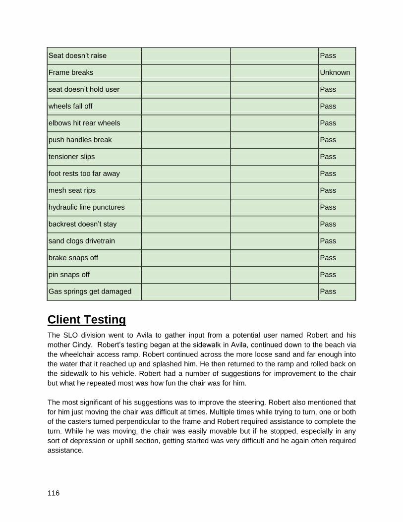
116
Seat doesn’t raise Pass
Frame breaks Unknown
seat doesn’t hold user Pass
wheels fall off Pass
elbows hit rear wheels Pass
push handles break Pass
tensioner slips Pass
foot rests too far away Pass
mesh seat rips Pass
hydraulic line punctures Pass
backrest doesn’t stay Pass
sand clogs drivetrain Pass
brake snaps off Pass
pin snaps off Pass
Gas springs get damaged Pass
Client Testing
The SLO division went to Avila to gather input from a potential user named Robert and his
mother Cindy. Robert’s testing began at the sidewalk in Avila, continued down to the beach via
the wheelchair access ramp. Robert continued across the more loose sand and far enough into
the water that it reached up and splashed him. He then returned to the ramp and rolled back on
the sidewalk to his vehicle. Robert had a number of suggestions for improvement to the chair
but what he repeated most was how fun the chair was for him.
The most significant of his suggestions was to improve the steering. Robert also mentioned that
for him just moving the chair was difficult at times. Multiple times while trying to turn, one or both
of the casters turned perpendicular to the frame and Robert required assistance to complete the
turn. While he was moving, the chair was easily movable but if he stopped, especially in any
sort of depression or uphill section, getting started was very difficult and he again often required
assistance.
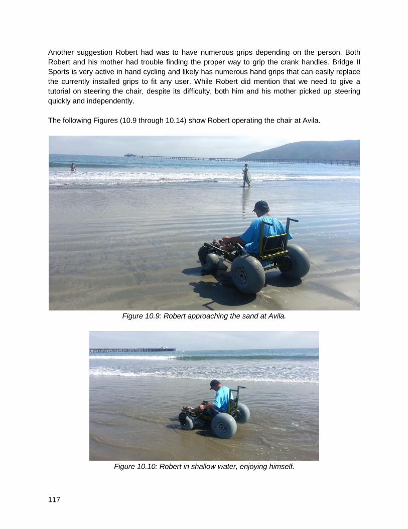
117
Another suggestion Robert had was to have numerous grips depending on the person. Both
Robert and his mother had trouble finding the proper way to grip the crank handles. Bridge II
Sports is very active in hand cycling and likely has numerous hand grips that can easily replace
the currently installed grips to fit any user. While Robert did mention that we need to give a
tutorial on steering the chair, despite its difficulty, both him and his mother picked up steering
quickly and independently.
The following Figures (10.9 through 10.14) show Robert operating the chair at Avila.
Figure 10.9: Robert approaching the sand at Avila.
Figure 10.10: Robert in shallow water, enjoying himself.
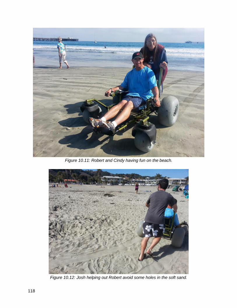
118
Figure 10.11: Robert and Cindy having fun on the beach.
Figure 10.12: Josh helping out Robert avoid some holes in the soft sand.
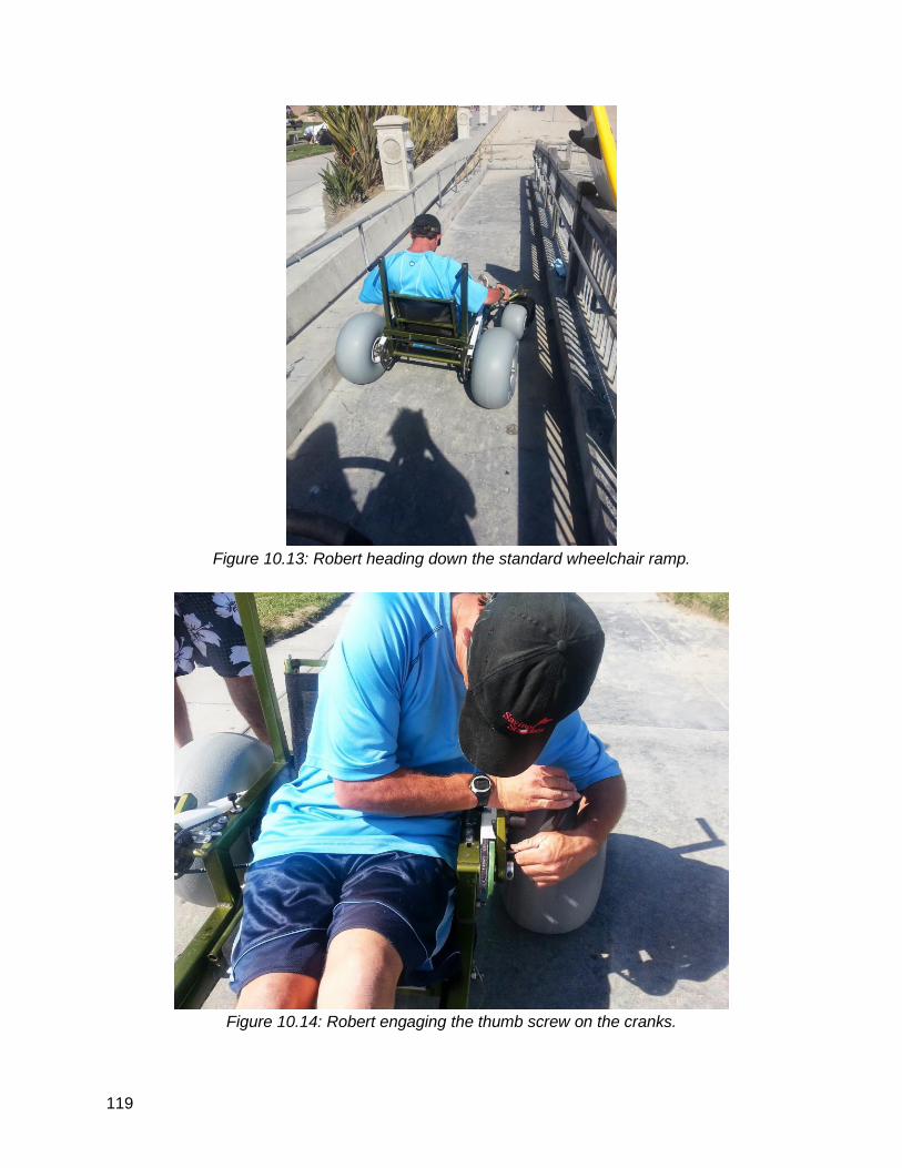
119
Figure 10.13: Robert heading down the standard wheelchair ramp.
Figure 10.14: Robert engaging the thumb screw on the cranks.
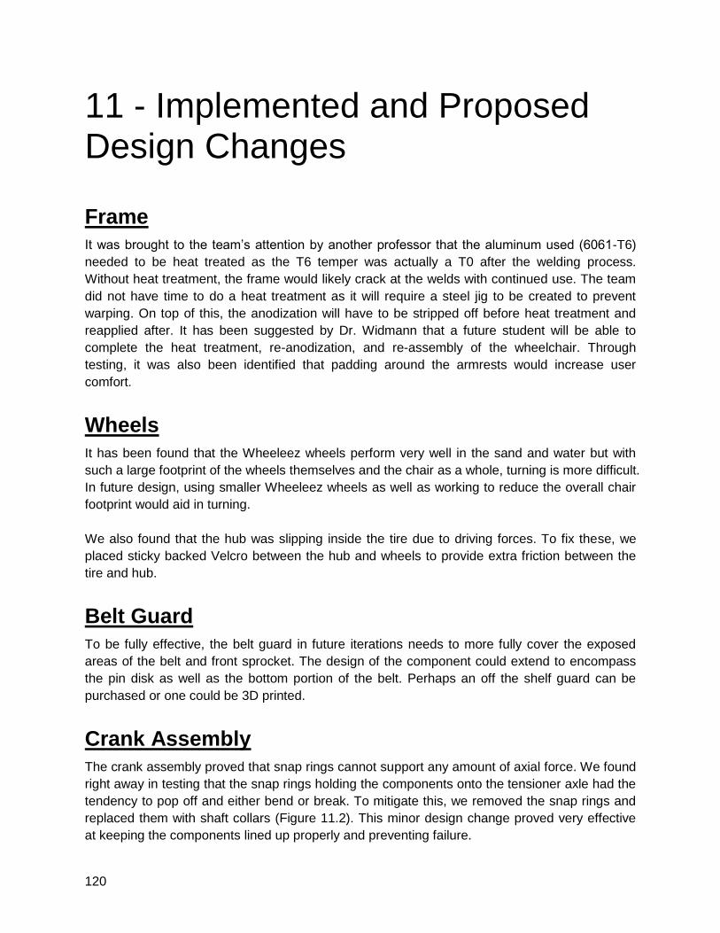
120
11 - Implemented and Proposed Design Changes
Frame
It was brought to the team’s attention by another professor that the aluminum used (6061-T6)
needed to be heat treated as the T6 temper was actually a T0 after the welding process.
Without heat treatment, the frame would likely crack at the welds with continued use. The team
did not have time to do a heat treatment as it will require a steel jig to be created to prevent
warping. On top of this, the anodization will have to be stripped off before heat treatment and
reapplied after. It has been suggested by Dr. Widmann that a future student will be able to
complete the heat treatment, re-anodization, and re-assembly of the wheelchair. Through
testing, it was also been identified that padding around the armrests would increase user
comfort.
Wheels
It has been found that the Wheeleez wheels perform very well in the sand and water but with
such a large footprint of the wheels themselves and the chair as a whole, turning is more difficult.
In future design, using smaller Wheeleez wheels as well as working to reduce the overall chair
footprint would aid in turning.
We also found that the hub was slipping inside the tire due to driving forces. To fix these, we
placed sticky backed Velcro between the hub and wheels to provide extra friction between the
tire and hub.
Belt Guard
To be fully effective, the belt guard in future iterations needs to more fully cover the exposed
areas of the belt and front sprocket. The design of the component could extend to encompass
the pin disk as well as the bottom portion of the belt. Perhaps an off the shelf guard can be
purchased or one could be 3D printed.
Crank Assembly
The crank assembly proved that snap rings cannot support any amount of axial force. We found
right away in testing that the snap rings holding the components onto the tensioner axle had the
tendency to pop off and either bend or break. To mitigate this, we removed the snap rings and
replaced them with shaft collars (Figure 11.2). This minor design change proved very effective
at keeping the components lined up properly and preventing failure.
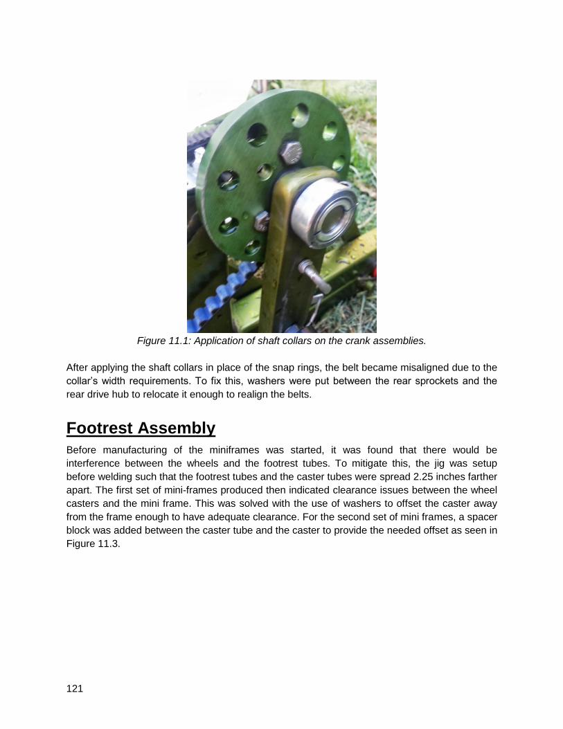
121
Figure 11.1: Application of shaft collars on the crank assemblies.
After applying the shaft collars in place of the snap rings, the belt became misaligned due to the
collar’s width requirements. To fix this, washers were put between the rear sprockets and the
rear drive hub to relocate it enough to realign the belts.
Footrest Assembly
Before manufacturing of the miniframes was started, it was found that there would be
interference between the wheels and the footrest tubes. To mitigate this, the jig was setup
before welding such that the footrest tubes and the caster tubes were spread 2.25 inches farther
apart. The first set of mini-frames produced then indicated clearance issues between the wheel
casters and the mini frame. This was solved with the use of washers to offset the caster away
from the frame enough to have adequate clearance. For the second set of mini frames, a spacer
block was added between the caster tube and the caster to provide the needed offset as seen in
Figure 11.3.
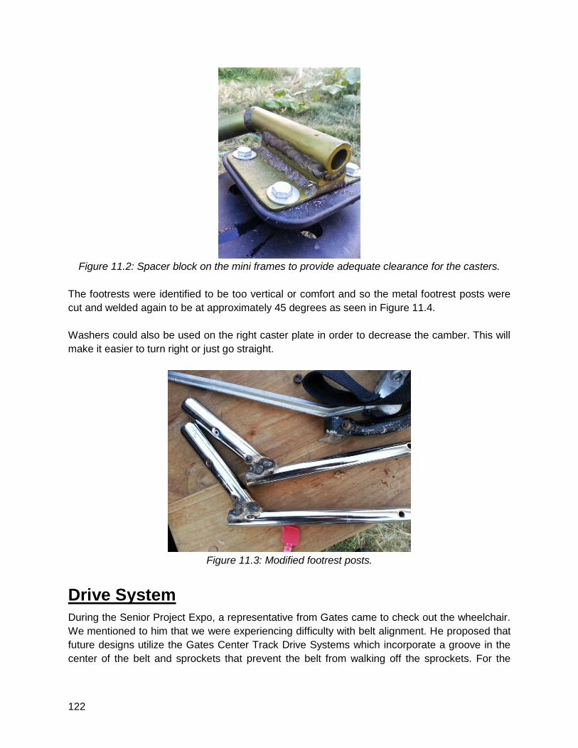
122
Figure 11.2: Spacer block on the mini frames to provide adequate clearance for the casters.
The footrests were identified to be too vertical or comfort and so the metal footrest posts were
cut and welded again to be at approximately 45 degrees as seen in Figure 11.4.
Washers could also be used on the right caster plate in order to decrease the camber. This will
make it easier to turn right or just go straight.
Figure 11.3: Modified footrest posts.
Drive System
During the Senior Project Expo, a representative from Gates came to check out the wheelchair.
We mentioned to him that we were experiencing difficulty with belt alignment. He proposed that
future designs utilize the Gates Center Track Drive Systems which incorporate a groove in the
center of the belt and sprockets that prevent the belt from walking off the sprockets. For the
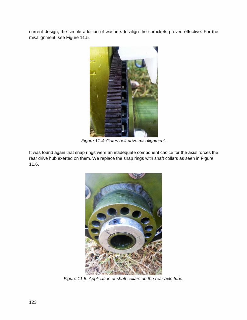
123
current design, the simple addition of washers to align the sprockets proved effective. For the
misalignment, see Figure 11.5.
Figure 11.4: Gates belt drive misalignment.
It was found again that snap rings were an inadequate component choice for the axial forces the
rear drive hub exerted on them. We replace the snap rings with shaft collars as seen in Figure
11.6.
Figure 11.5: Application of shaft collars on the rear axle tube.
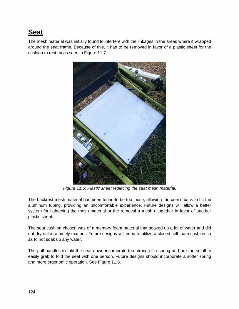
124
Seat
The mesh material was initially found to interfere with the linkages in the areas where it wrapped
around the seat frame. Because of this, it had to be removed in favor of a plastic sheet for the
cushion to rest on as seen in Figure 11.7.
Figure 11.6: Plastic sheet replacing the seat mesh material.
The backrest mesh material has been found to be too loose, allowing the user’s back to hit the
aluminum tubing, providing an uncomfortable experience. Future designs will allow a better
system for tightening the mesh material or the removal a mesh altogether in favor of another
plastic sheet.
The seat cushion chosen was of a memory foam material that soaked up a lot of water and did
not dry out in a timely manner. Future designs will need to utilize a closed cell foam cushion so
as to not soak up any water.
The pull handles to fold the seat down incorporate too strong of a spring and are too small to
easily grab to fold the seat with one person. Future designs should incorporate a softer spring
and more ergonomic operation. See Figure 11.8.
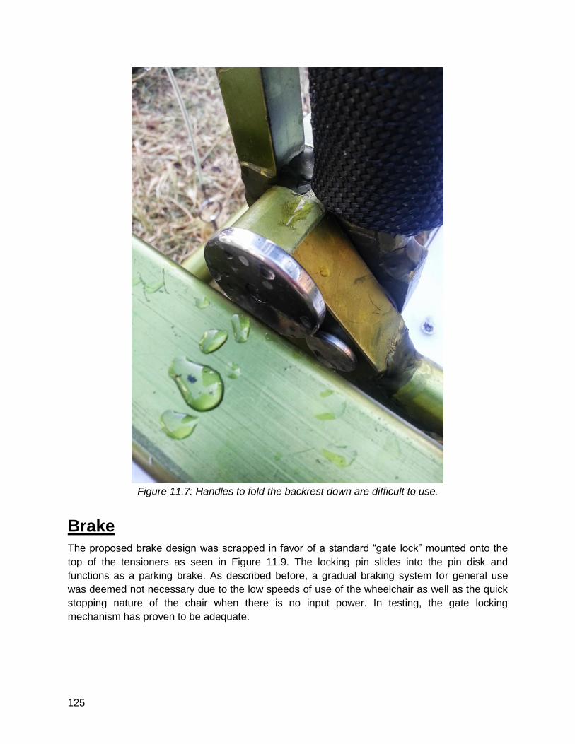
125
Figure 11.7: Handles to fold the backrest down are difficult to use.
Brake
The proposed brake design was scrapped in favor of a standard “gate lock” mounted onto the
top of the tensioners as seen in Figure 11.9. The locking pin slides into the pin disk and
functions as a parking brake. As described before, a gradual braking system for general use
was deemed not necessary due to the low speeds of use of the wheelchair as well as the quick
stopping nature of the chair when there is no input power. In testing, the gate locking
mechanism has proven to be adequate.
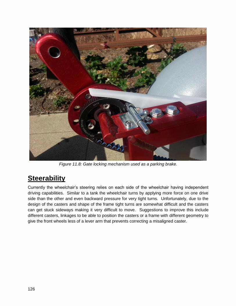
126
Figure 11.8: Gate locking mechanism used as a parking brake.
Steerability
Currently the wheelchair’s steering relies on each side of the wheelchair having independent
driving capabilities. Similar to a tank the wheelchair turns by applying more force on one drive
side than the other and even backward pressure for very tight turns. Unfortunately, due to the
design of the casters and shape of the frame tight turns are somewhat difficult and the casters
can get stuck sideways making it very difficult to move. Suggestions to improve this include
different casters, linkages to be able to position the casters or a frame with different geometry to
give the front wheels less of a lever arm that prevents correcting a misaligned caster.
127
12 - Closing Remarks
The engineering process of design, build, test, and report that we have gone through over the
last 9 months has been an exciting, creative, difficult, interesting, frustrating, fun, rewarding, and
educational experience. The international and interdisciplinary aspects of our team combined
with the technical rigor and manufacturing feat of building two complete wheelchairs pushed our
team to excel beyond the expectations of many, including ourselves. There were times of doubt,
worry, and plain unhappiness, but we pushed through them, believing we would find success.
And success we found.
From the standing ovation we received from the Industrial Advisory Board, to the first time we
launched the chair in the ocean at Avila Beach, to the time we frantically redesigned component
assemblies at the hardware store just an hour before the exposition, to when we first
successfully linked the Munich seat with our frame, each and every milestone has kept our
heads held high, propelling us to keep moving forward.
We have come a long way from our early prototypes and concept models to the final product we
have now. Looking back, we laugh at some of the ideas we had and continue to question many
of the elements of the current design. But what we recognize is that at the time, each decision
felt right and was valid with the information at hand. Each idea, each iteration, each “a-ha!” and
“uh-oh...” moment we have had was a necessary step to get where we are today. And perhaps
this is the biggest lesson we have learned: that design is not a one step process, but an iterative
and collaborative process that takes a lot of time, effort, and persistence. Though we had all
experienced this lesson to some degree in our other courses, senior project has been the
cementing factor to instill this knowledge in all of us.
It’s hard to believe after the 9 months working on this project that it’s finally coming to a close.
Though the chair is not perfect by any stretch, we feel satisfied in where we are leaving it; we
have never felt more successful than now. Thank you Bridge II Sports for the project inspiration
and guidance. Thank you to our sponsors: Gates, Wheeleez, Zitec, Elite Metal Finishing, and
Bike On. Thank you Kevin for the welding. And thank you Dr. Widmann and Dr. Maurer for your
support, humor, patience, and advice. It’s been fun.
- Team SandCrawler: Rory, Josh, Sam, Alex, Alexa,
Max, Bene, Marvin, and Marco
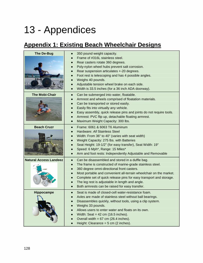
128
13 - Appendices
Appendix 1: Existing Beach Wheelchair Designs
The De-Bug
● 350 pound weight capacity.
● Frame of #316L stainless steel.
● Rear casters rotate 360 degrees.
● Poly-nylon wheel hubs prevent salt corrosion.
● Rear suspension articulates +-20 degrees.
● Foot rest is telescoping and has 4 possible angles.
● Weighs 40 pounds.
● Adjustable tension wheel brake on each side.
● Width is 33.5 inches (for a 36 inch ADA doorway).
The Mobi-Chair
● Can be submerged into water, floatable.
● Armrest and wheels comprised of floatation materials.
● Can be transported or stored easily.
● Easily fits into virtually any vehicle.
● Easy assembly, quick release pins and joints do not require tools.
● Armrest: PVC flip up, detachable floating armrest.
● Maximum Weight Capacity: 300 lbs.
Beach Cruzr
● Frame: 6061 & 6063 T6 Aluminum
● Hardware: All Stainless Steel
● Width: From 36" to 40" (varies with seat width)
● Weight Capacity: 275 lbs. with Batteries
● Seat Height: 19-1/2" (for easy transfer), Seat Width: 19"
● Speed: 6 Mph*, Range: 15 Miles*
● Arm and foot rests: Independently Adjustable and Removable
Natural Access Landeez
● Can be disassembled and stored in a duffle bag.
● The frame is constructed of marine-grade stainless steel.
● 360 degree omni-directional front casters.
● Most portable and convenient all-terrain wheelchair on the market.
● Complete set of quick release pins for easy transport and storage.
● The leg rest is adjustable in length and angle.
● Both armrests can be raised for easy transfer.
Hippocampe
● Seat is made of closed-cell water-resistance foam.
● Axles are made of stainless steel without ball bearings.
● Disassembles quickly, without tools, using a clip system.
● Weighs 33 pounds.
● Allows users to enter water and floats on its own.
● Width: Seat = 42 cm (16.5 inches).
● Overall width = 67 cm (26.4 inches).
● Height: Clearance = 5 cm (2 inches).
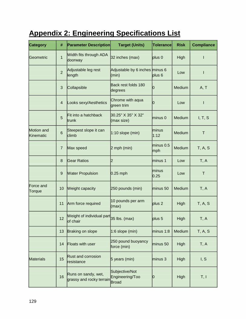
129
Appendix 2: Engineering Specifications List
Category # Parameter Description Target (Units) Tolerance Risk Compliance
Geometric 1 Width fits through ADA
doorway 32 inches (max) plus 0 High I
2 Adjustable leg rest
length
Adjustable by 6 inches
(min)
minus 6
plus 6 Low I
3 Collapsible Back rest folds 180
degrees 0 Medium A, T
4 Looks sexy/Aesthetics Chrome with aqua
green trim 0 Low I
5 Fit into a hatchback
trunk
30.25" X 35" X 32"
(max size) minus 0 Medium I, T, S
Motion and
Kinematic 6
Steepest slope it can
climb 1:10 slope (min)
minus
1:12 Medium T
7 Max speed 2 mph (min) minus 0.5
mph Medium T, A, S
8 Gear Ratios 2 minus 1 Low T, A
9 Water Propulsion 0.25 mph minus
0.25 Low T
Force and
Torque 10 Weight capacity 250 pounds (min) minus 50 Medium T, A
11 Arm force required 10 pounds per arm
(max) plus 2 High T, A, S
12 Weight of individual part
of chair 35 lbs. (max) plus 5 High T, A
13 Braking on slope 1:6 slope (min) minus 1:8 Medium T, A, S
14 Floats with user 250 pound buoyancy
force (min) minus 50 High T, A
Materials 15 Rust and corrosion
resistance 5 years (min) minus 3 High I, S
16 Runs on sandy, wet,
grassy and rocky terrain
Subjective/Not
Engineering/Too
Broad
0 High T, I
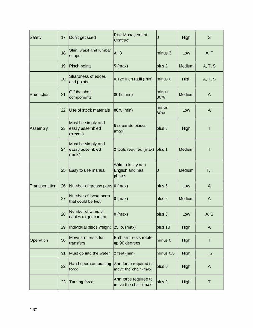
130
Safety 17 Don’t get sued Risk Management
Contract 0 High S
18 Shin, waist and lumbar
straps All 3 minus 3 Low A, T
19 Pinch points 5 (max) plus 2 Medium A, T, S
20 Sharpness of edges
and points 0.125 inch radii (min) minus 0 High A, T, S
Production 21 Off the shelf
components 80% (min)
minus
30% Medium A
22 Use of stock materials 80% (min) minus
30% Low A
Assembly 23
Must be simply and
easily assembled
(pieces)
5 separate pieces
(max) plus 5 High T
24
Must be simply and
easily assembled
(tools)
2 tools required (max) plus 1 Medium T
25 Easy to use manual
Written in layman
English and has
photos
0 Medium T, I
Transportation 26 Number of greasy parts 0 (max) plus 5 Low A
27 Number of loose parts
that could be lost 0 (max) plus 5 Medium A
28 Number of wires or
cables to get caught 0 (max) plus 3 Low A, S
29 Individual piece weight 25 lb. (max) plus 10 High A
Operation 30 Move arm rests for
transfers
Both arm rests rotate
up 90 degrees minus 0 High T
31 Must go into the water 2 feet (min) minus 0.5 High I, S
32 Hand operated braking
force
Arm force required to
move the chair (max) plus 0 High A
33 Turning force Arm force required to
move the chair (max) plus 0 High T
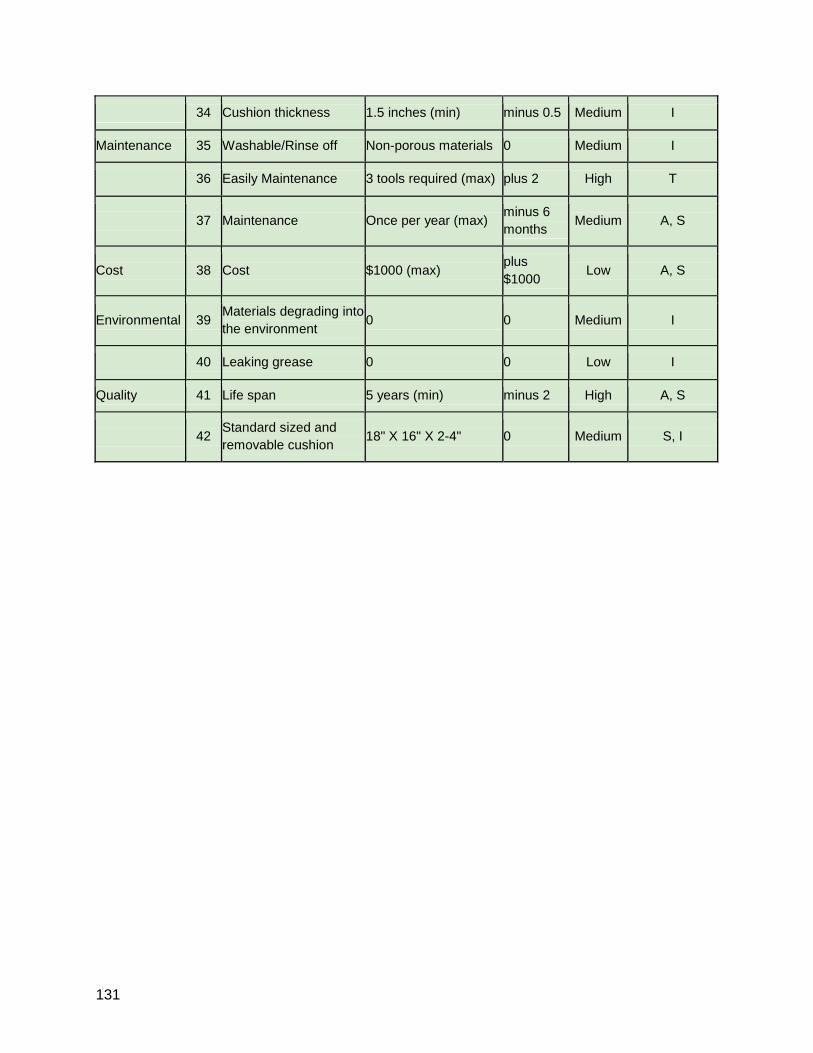
131
34 Cushion thickness 1.5 inches (min) minus 0.5 Medium I
Maintenance 35 Washable/Rinse off Non-porous materials 0 Medium I
36 Easily Maintenance 3 tools required (max) plus 2 High T
37 Maintenance Once per year (max) minus 6
months Medium A, S
Cost 38 Cost $1000 (max) plus
$1000 Low A, S
Environmental 39 Materials degrading into
the environment 0 0 Medium I
40 Leaking grease 0 0 Low I
Quality 41 Life span 5 years (min) minus 2 High A, S
42 Standard sized and
removable cushion 18" X 16" X 2-4" 0 Medium S, I
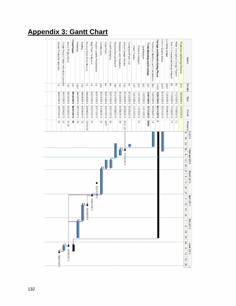
132
Appendix 3: Gantt Chart
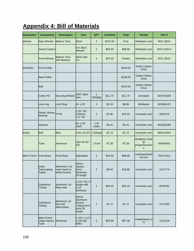
133
Appendix 4: Bill of Materials
Subsystem Component Description Size QTY Cost/Unit Total Vender Part #
Wheels Rear Wheels Balloon Tires 49cm 2 $137.00 Free Wheeleez.com WZ1-49UC
Swivel Casters For 30cm Wheels 2 $29.00 $58.00 Wheeleez.com WZ1-CAS-S
Front Wheels Balloon Tires with Bearing
30cm with 1in 2 $76.00 Freeee Wheeleez.com WZ1-30UC
Drivetrain Front Pulley $130.00 Gates Carbon Drive
Rear Pulley $130.00 Gates Carbon Drive
Belt $130.00 Gates Carbon Drive
Cotter Pin Securing Wheels 3/32" diam wire
1 (25/pkg) $11.75 $11.75 mcmaster 92375A348
Lock ring Lock Ring for 1.25" 4 $2.24 $8.96 McMaster 91590A137
Plastic Sleeve Bearing PTFE
1.25" OD, t=20mm, 1.5" OD
2 $7.96 $15.92 mcmaster.com 2610T43
washers for 1.25" shaft
1 (9 units) $4.41 $4.41 mcmaster.com 90126A039
Brake Bolt Blue 1/2in 1/4-20 1 (5/bag) $7.14 $7.14 mcmaster.com 98511A643
Tube Aluminum .652 ID 3/4" OD 1 Foot $7.39 $7.39
McMaster (look @
polyperformance
9056K693
Main Frame Foot Rests Foot Rests Adjustable 2 $34.00 $68.00 southwestmedical.com RP17x012
Outer Telescoping Tubes
Aluminum, For main frame to wheel frames
25mm square, 2mm thickness, 2ft length
2 $9.94 $19.88 mcmaster.com 1471T74
Cylindrical Tubing
Aluminum, for Rear Axle
1-1/4" OD, 4' length with 0.12" thickness
1 $54.25 $54.25 mcmaster.com 9578T52
Cylindrical Tubing
Aluminum, for foot rest telescoping
20mm Aluminum Round Tubing 2mm thick 2ft length
1 $7.11 $7.11 mcmaster.com 1471T83
Main Frame Large Square Tube
Aluminum 1-1/2 x 1-1/2 x 1/8 wall 6063
2 $43.68 $87.36 metalsdepot.com T311218
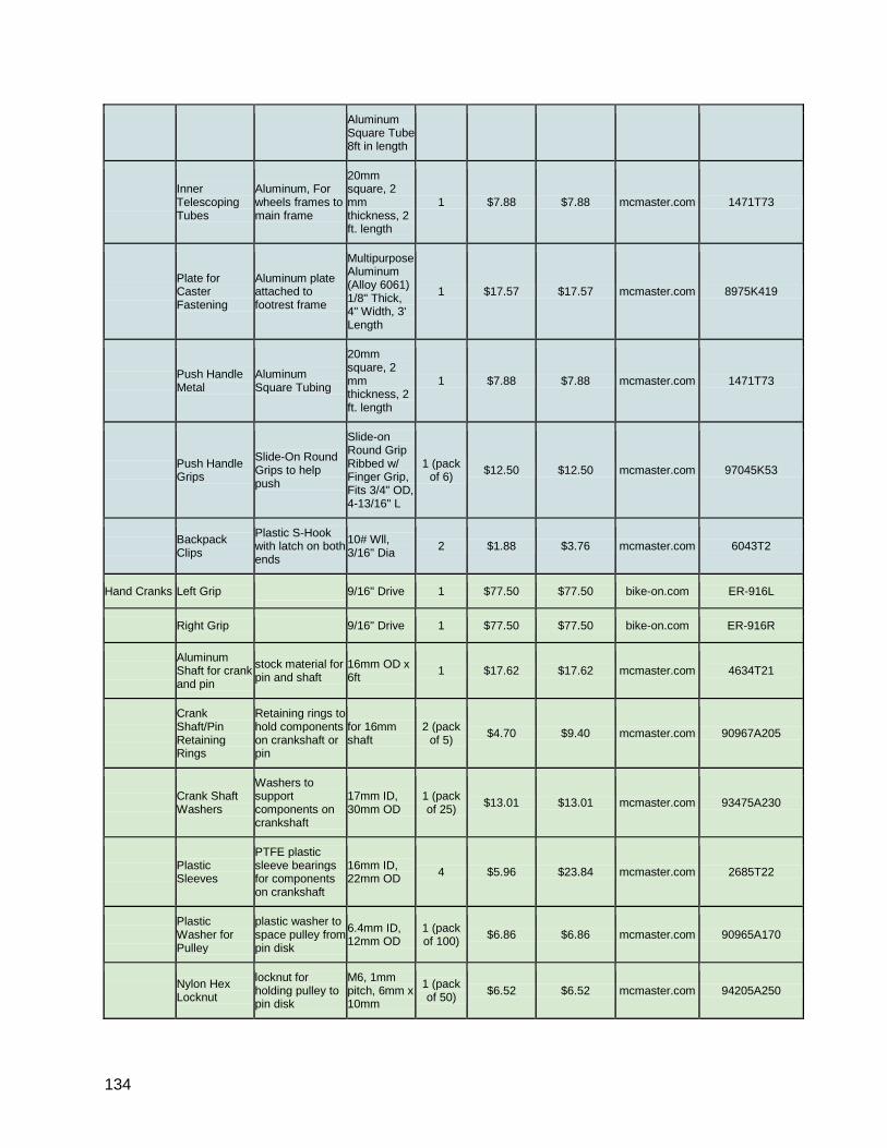
134
Aluminum Square Tube 8ft in length
Inner Telescoping Tubes
Aluminum, For wheels frames to main frame
20mm square, 2 mm thickness, 2 ft. length
1 $7.88 $7.88 mcmaster.com 1471T73
Plate for Caster Fastening
Aluminum plate attached to footrest frame
Multipurpose Aluminum (Alloy 6061) 1/8" Thick, 4" Width, 3' Length
1 $17.57 $17.57 mcmaster.com 8975K419
Push Handle Metal
Aluminum Square Tubing
20mm square, 2 mm thickness, 2 ft. length
1 $7.88 $7.88 mcmaster.com 1471T73
Push Handle Grips
Slide-On Round Grips to help push
Slide-on Round Grip Ribbed w/ Finger Grip, Fits 3/4" OD, 4-13/16" L
1 (pack of 6) $12.50 $12.50 mcmaster.com 97045K53
Backpack Clips
Plastic S-Hook with latch on both ends
10# Wll, 3/16" Dia 2 $1.88 $3.76 mcmaster.com 6043T2
Hand Cranks Left Grip 9/16" Drive 1 $77.50 $77.50 bike-on.com ER-916L
Right Grip 9/16" Drive 1 $77.50 $77.50 bike-on.com ER-916R
Aluminum Shaft for crank and pin
stock material for pin and shaft
16mm OD x 6ft 1 $17.62 $17.62 mcmaster.com 4634T21
Crank Shaft/Pin Retaining Rings
Retaining rings to hold components on crankshaft or pin
for 16mm shaft
2 (pack of 5) $4.70 $9.40 mcmaster.com 90967A205
Crank Shaft Washers
Washers to support components on crankshaft
17mm ID, 30mm OD
1 (pack of 25) $13.01 $13.01 mcmaster.com 93475A230
Plastic Sleeves
PTFE plastic sleeve bearings for components on crankshaft
16mm ID, 22mm OD 4 $5.96 $23.84 mcmaster.com 2685T22
Plastic Washer for Pulley
plastic washer to space pulley from pin disk
6.4mm ID, 12mm OD
1 (pack of 100) $6.86 $6.86 mcmaster.com 90965A170
Nylon Hex Locknut
locknut for holding pulley to pin disk
M6, 1mm pitch, 6mm x 10mm
1 (pack of 50) $6.52 $6.52 mcmaster.com 94205A250
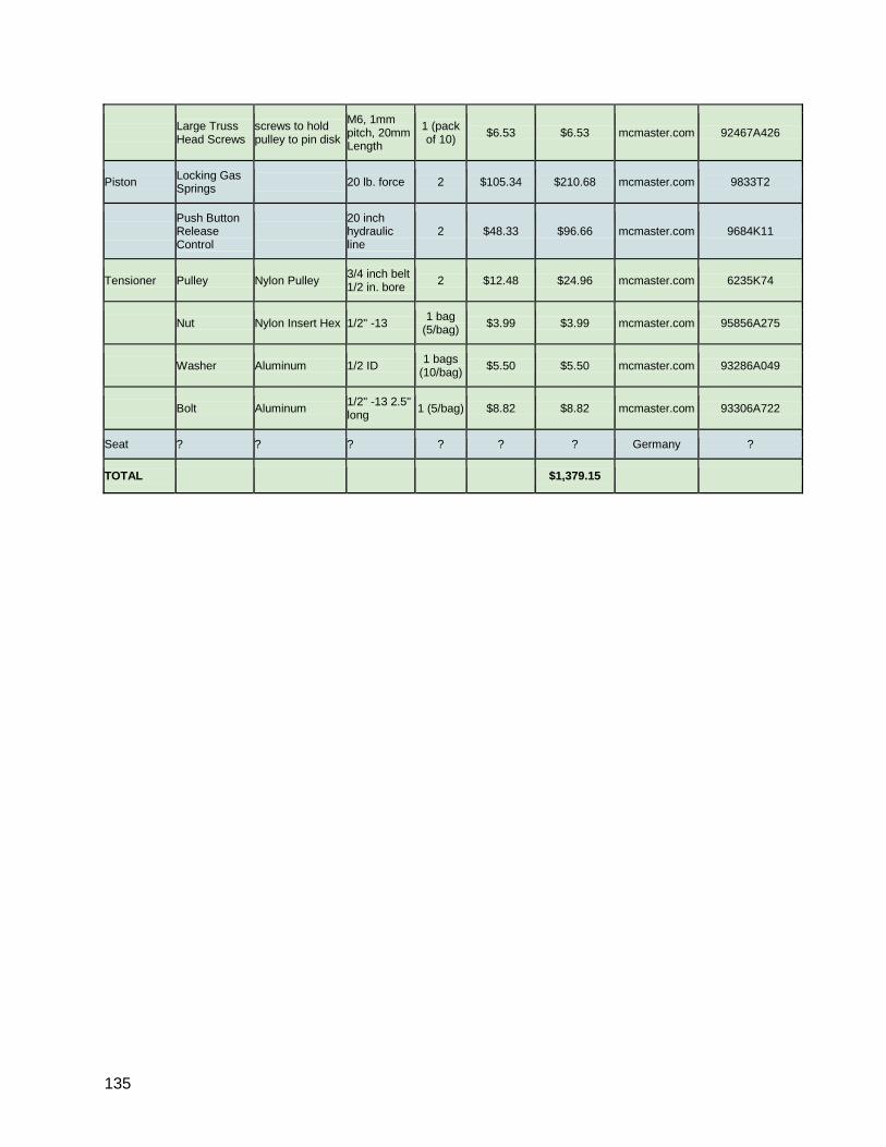
135
Large Truss Head Screws
screws to hold pulley to pin disk
M6, 1mm pitch, 20mm Length
1 (pack of 10) $6.53 $6.53 mcmaster.com 92467A426
Piston Locking Gas Springs 20 lb. force 2 $105.34 $210.68 mcmaster.com 9833T2
Push Button Release Control
20 inch hydraulic line
2 $48.33 $96.66 mcmaster.com 9684K11
Tensioner Pulley Nylon Pulley 3/4 inch belt 1/2 in. bore 2 $12.48 $24.96 mcmaster.com 6235K74
Nut Nylon Insert Hex 1/2" -13 1 bag (5/bag) $3.99 $3.99 mcmaster.com 95856A275
Washer Aluminum 1/2 ID 1 bags (10/bag) $5.50 $5.50 mcmaster.com 93286A049
Bolt Aluminum 1/2" -13 2.5" long 1 (5/bag) $8.82 $8.82 mcmaster.com 93306A722
Seat ? ? ? ? ? ? Germany ?
TOTAL $1,379.15
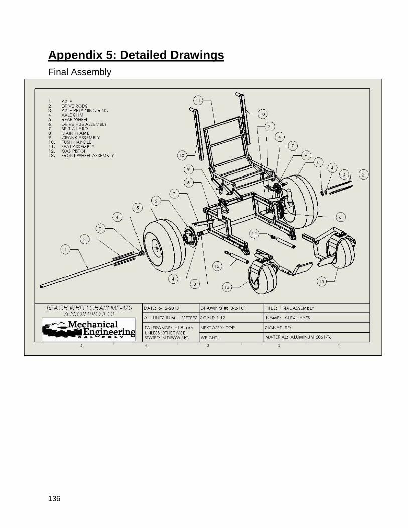
136
Appendix 5: Detailed Drawings
Final Assembly

137
Main Frame
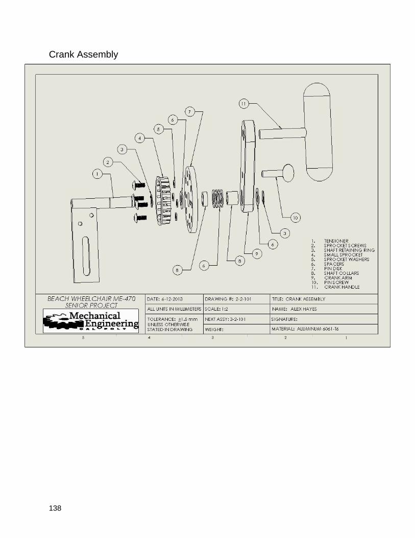
138
Crank Assembly
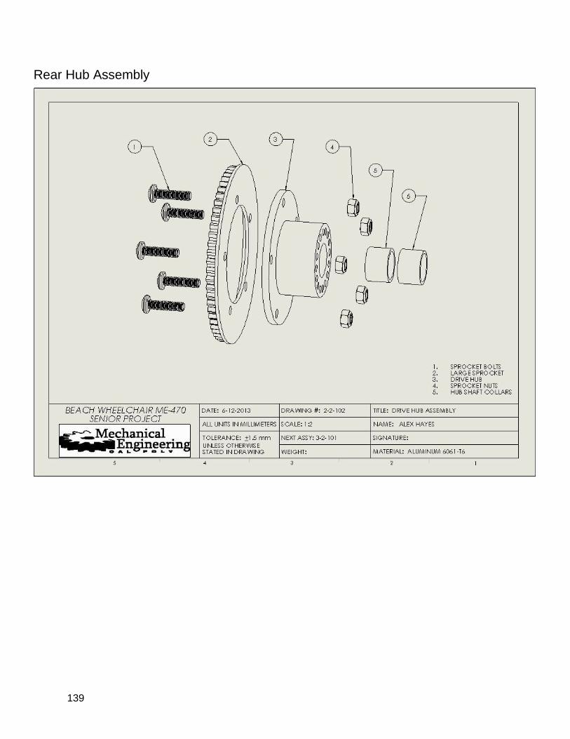
139
Rear Hub Assembly
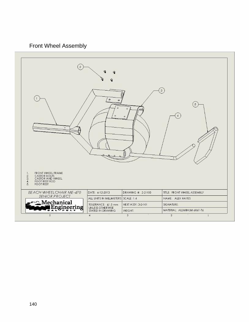
140
Front Wheel Assembly
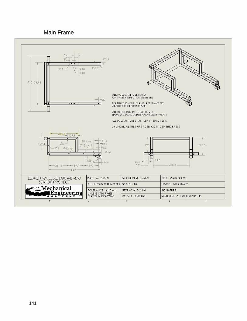
141
Main Frame
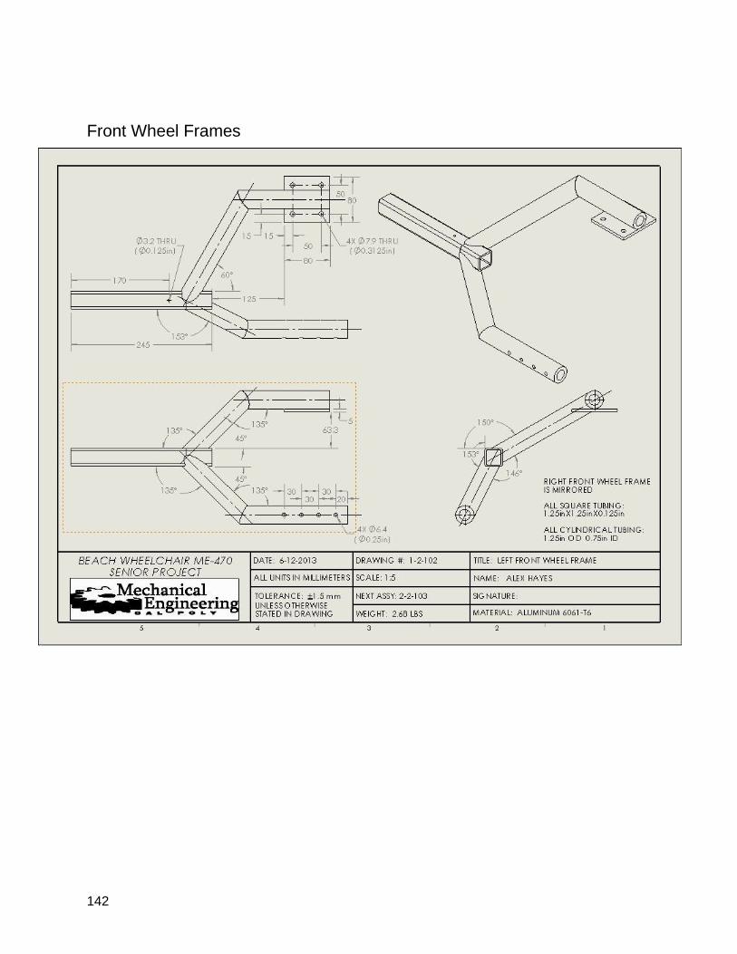
142
Front Wheel Frames
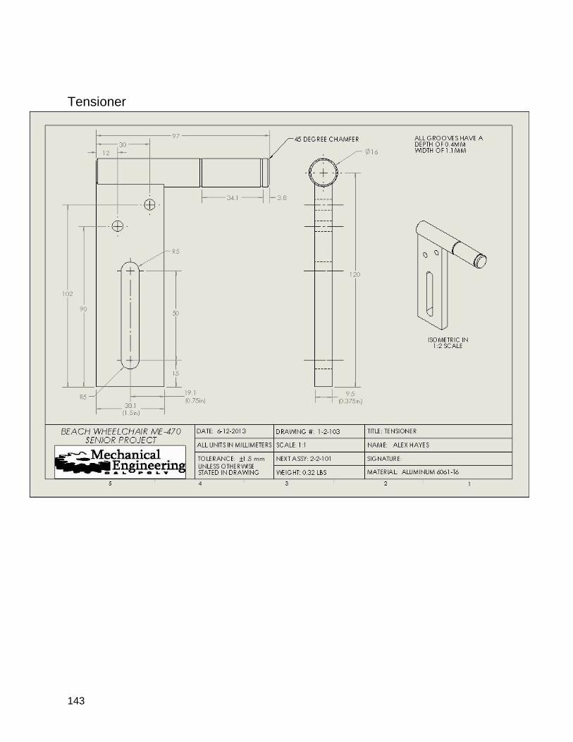
143
Tensioner

144
Pin Disk
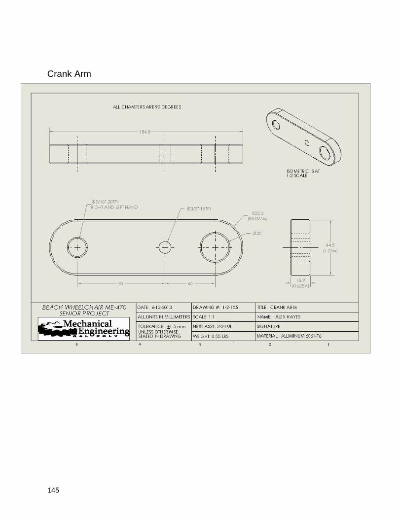
145
Crank Arm
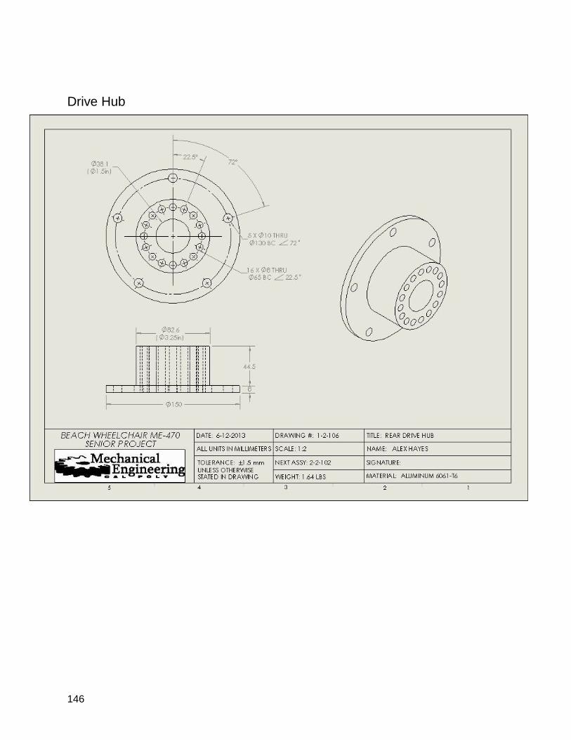
146
Drive Hub
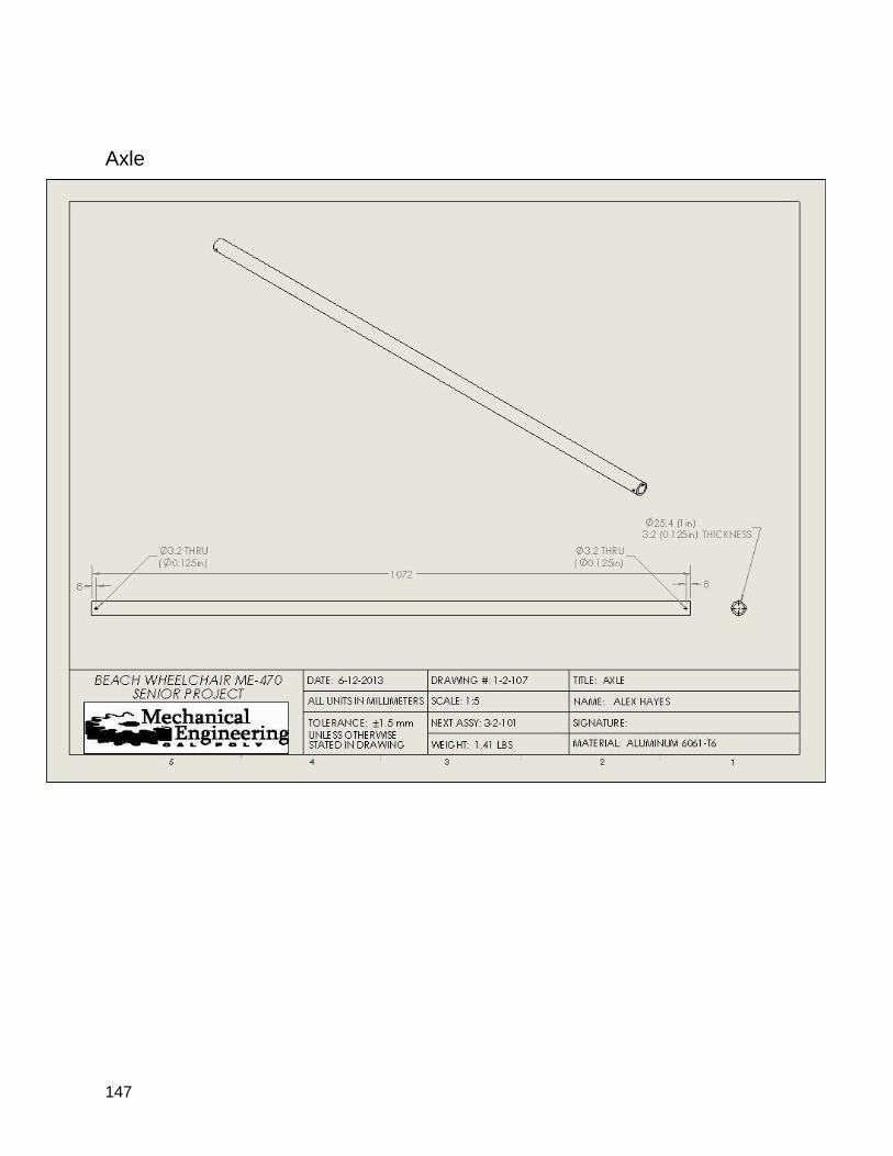
147
Axle
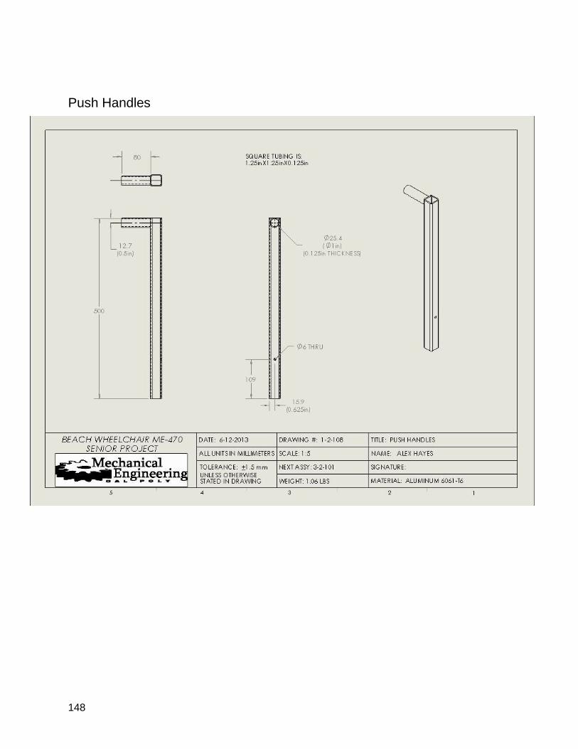
148
Push Handles
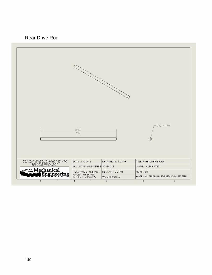
149
Rear Drive Rod
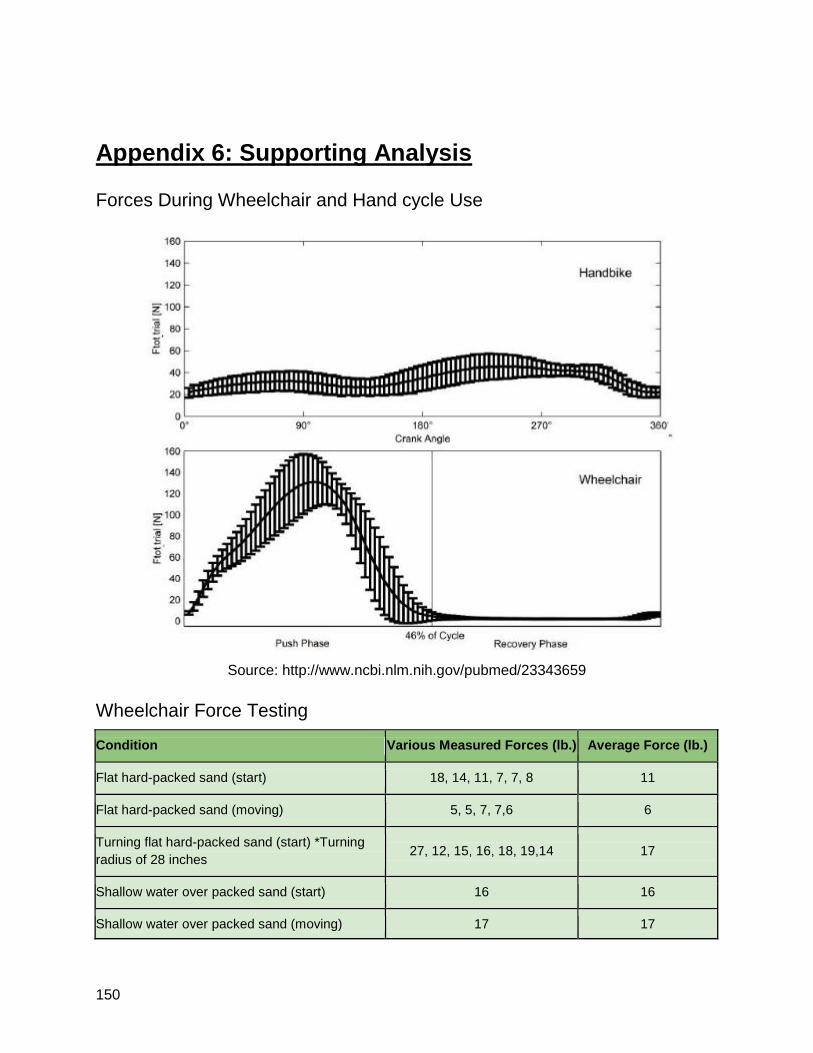
150
Appendix 6: Supporting Analysis
Forces During Wheelchair and Hand cycle Use
Source: http://www.ncbi.nlm.nih.gov/pubmed/23343659
Wheelchair Force Testing
Condition Various Measured Forces (lb.) Average Force (lb.)
Flat hard-packed sand (start) 18, 14, 11, 7, 7, 8 11
Flat hard-packed sand (moving) 5, 5, 7, 7,6 6
Turning flat hard-packed sand (start) *Turning
radius of 28 inches 27, 12, 15, 16, 18, 19,14 17
Shallow water over packed sand (start) 16 16
Shallow water over packed sand (moving) 17 17
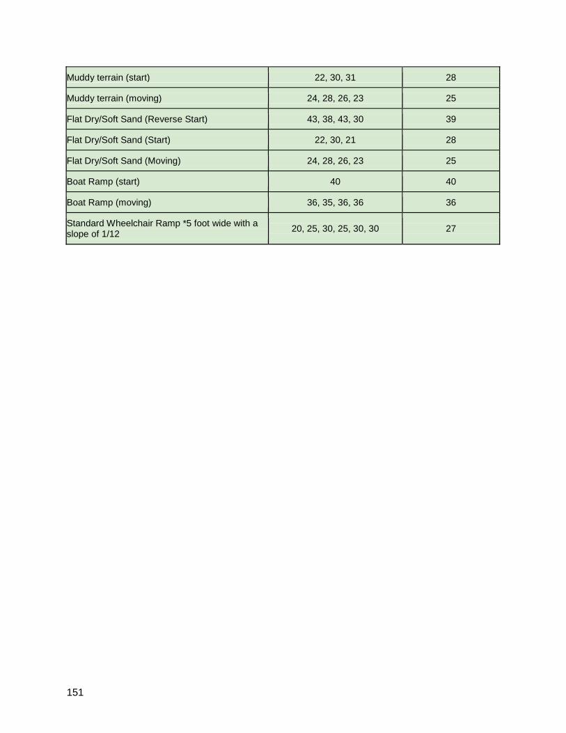
151
Muddy terrain (start) 22, 30, 31 28
Muddy terrain (moving) 24, 28, 26, 23 25
Flat Dry/Soft Sand (Reverse Start) 43, 38, 43, 30 39
Flat Dry/Soft Sand (Start) 22, 30, 21 28
Flat Dry/Soft Sand (Moving) 24, 28, 26, 23 25
Boat Ramp (start) 40 40
Boat Ramp (moving) 36, 35, 36, 36 36
Standard Wheelchair Ramp *5 foot wide with a slope of 1/12
20, 25, 30, 25, 30, 30 27
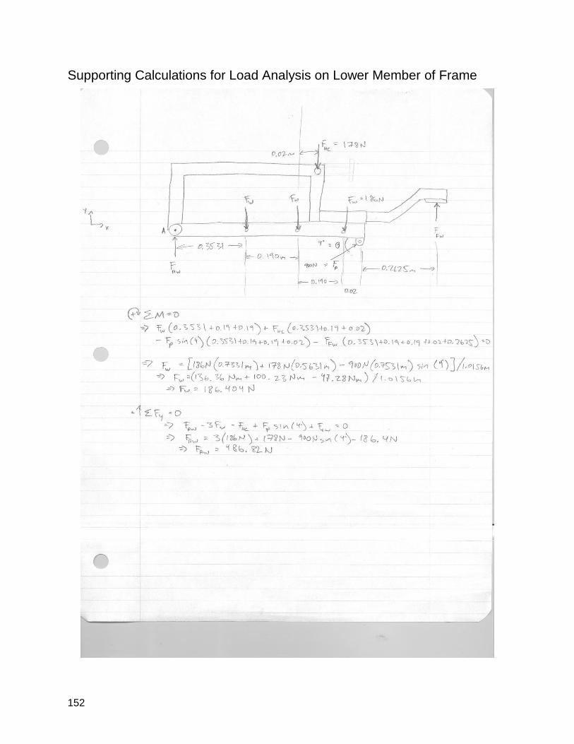
152
Supporting Calculations for Load Analysis on Lower Member of Frame
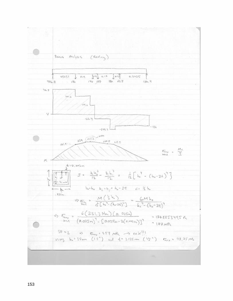
153
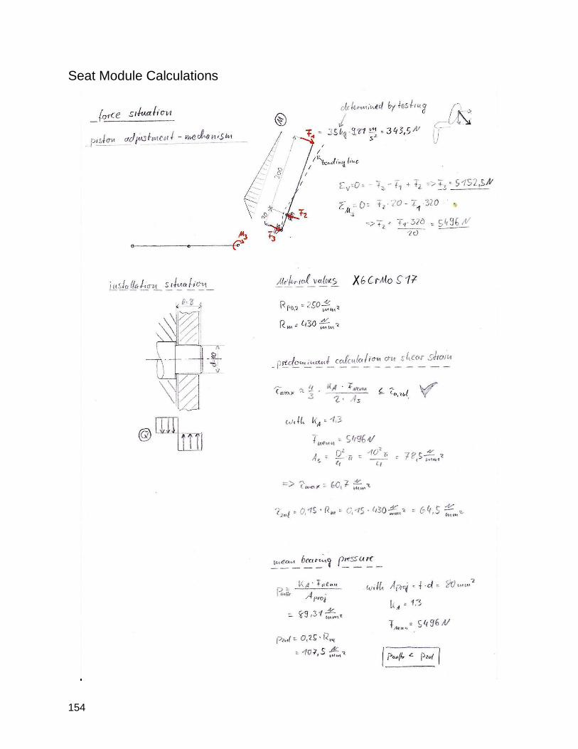
154
Seat Module Calculations
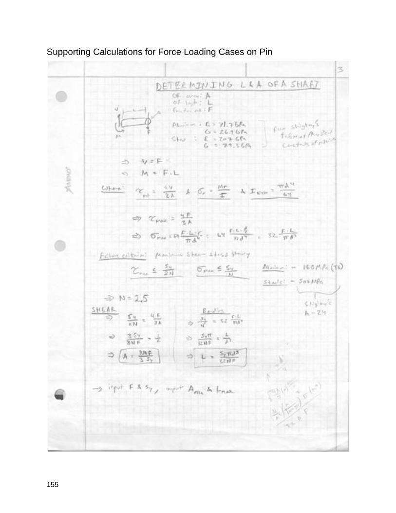
155
Supporting Calculations for Force Loading Cases on Pin
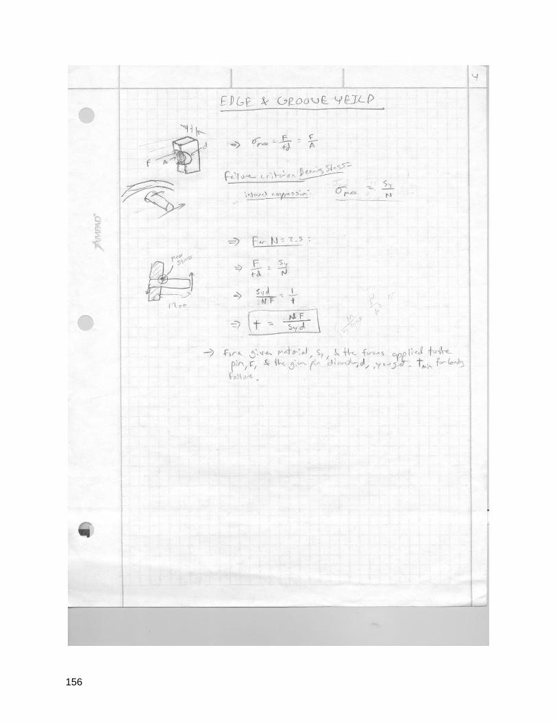
156
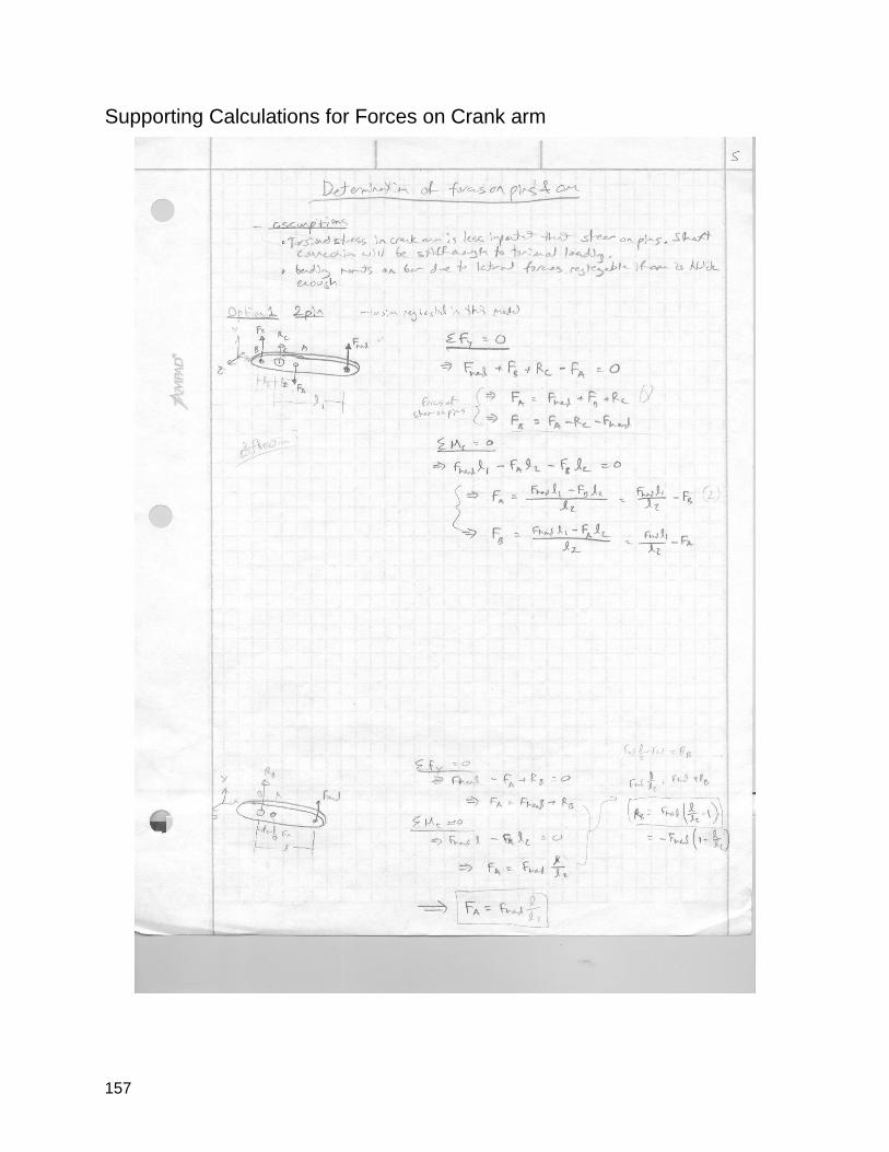
157
Supporting Calculations for Forces on Crank arm
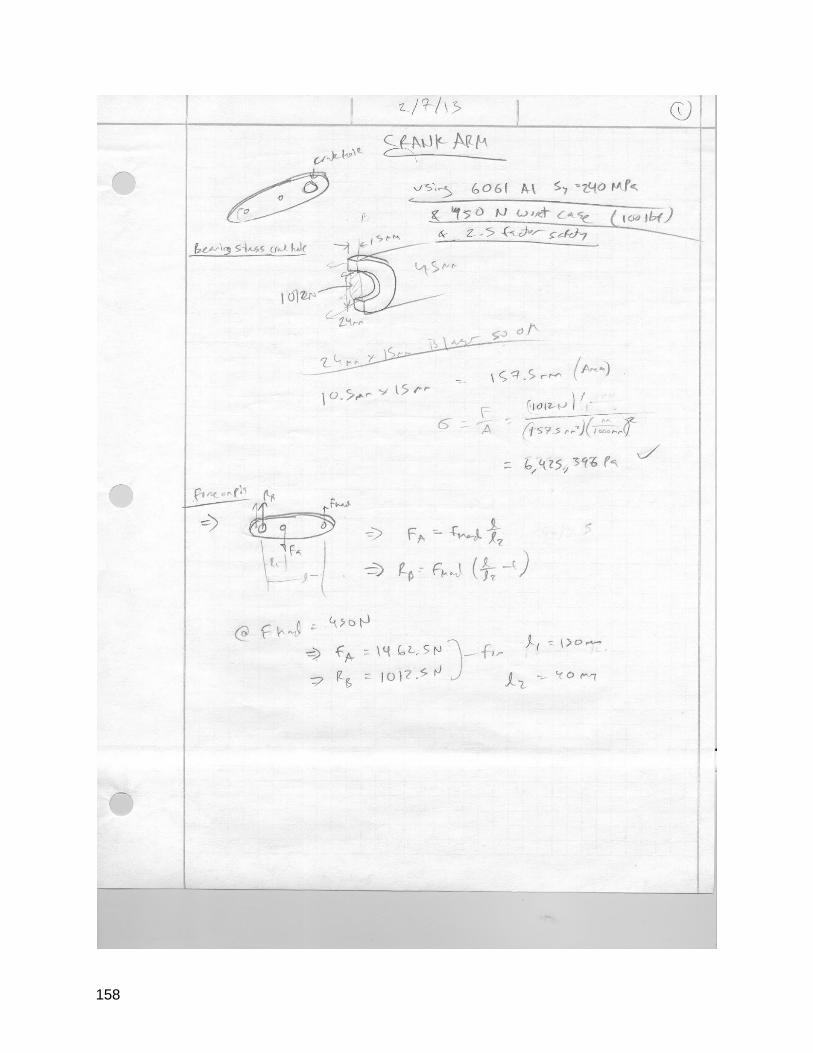
158
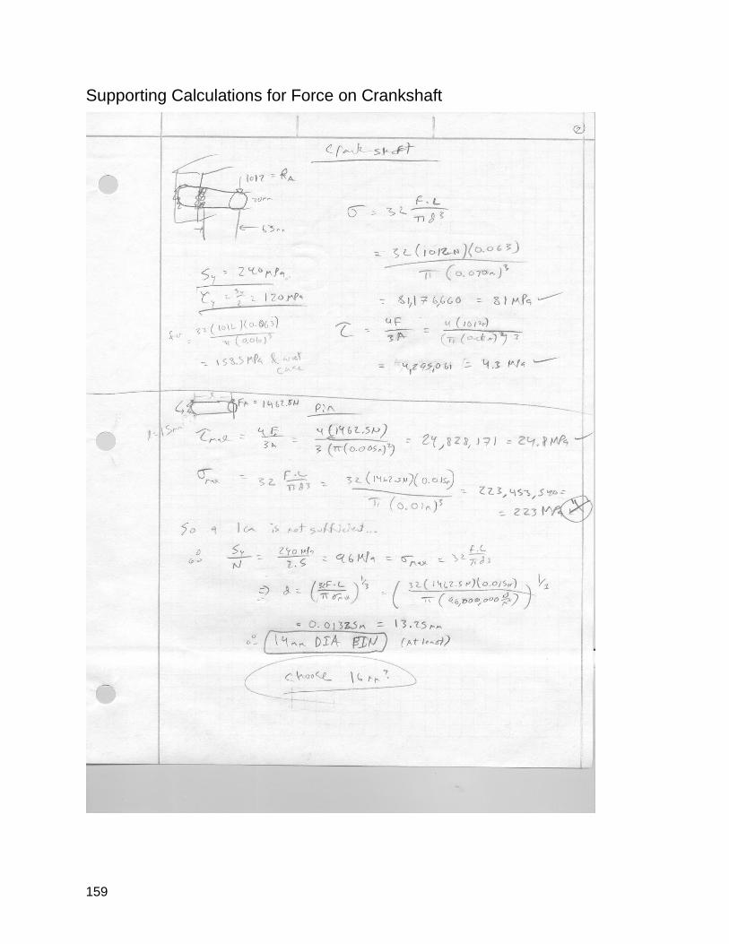
159
Supporting Calculations for Force on Crankshaft
160
Appendix 7: Team Contract
10/11/12
Team Sandspitter Contract Member Roles and Responsibilities
● Rory
○ Primary Contact with Bridge II Sports.
● Joshua
○ Primary Contact with Munich Division
● Sam
○ Meeting Scheduler
● Alex
○ Primary Contact with Kinesiology Division
Commitment and Accountability ● Team SLO meetings will be held every Thursday starting at 3:15 pm in 192-329. Each
meeting will start with a status report with Dr. Widmann and then will proceed as normal.
● For Fall quarter, weekly meetings with Team Munich will be held from 10-11 AM every
Wednesday via video conference.
● Additional meetings will be scheduled as necessary based on availability.
● Unless prearranged, should a group member miss a meeting, the group member will
have to sign a copy of the weekly status report to show that they understand what they
missed and prepare a creative apology to the group.
● Should a group member miss more than one meeting a quarter, they will provide the
team with an in person response as to why more than one meeting was missed and
what actions they will take to ensure no further meetings are missed.
Communication Pathways ● Contact will take place through the channels listed on the Team Info spreadsheet.
● Most communication that is not in person will be through text, calls, and emails.
○ Texts and calls will be responded to within a few hours.
○ Email will have a turnaround time of 1 day.
● Communication with Team Munich will take place through email or video conferences.
● Kinesiology students will be kept up to date via email and occasional group meetings.
● All project information will be kept for everyone to access in the Google Drive folder.
Conflict Resolution
161
● At the beginning of every meeting, the team will discuss the performance of each
member. If one is not pulling their weight or being a poor team member in any other way,
this will be the time to bring it up.
● Every team member is expected to take advice and constructive criticism without any
hard feelings.
● Every team member is expected to make a conscious effort to correct any shortcomings
that have been brought up.
● If a team member does not make an effort to correct shortcomings, then the subject will
be brought up during the Thursday meeting with Dr. Widmann.
Project Room Civility ● Terms of ethical behavior
○ Use the golden rule.
○ Use language that respects people that are disabled.
○ Inside voices should be used -- no yelling at people.
● Food/Drink
○ Respect the rules of the room being used
○ Each person is responsible for items brought to meetings
● Cleanup
○ Each team member cleans up after themselves.
○ If a mess still exists after, every team member is expected to step up and help
get the cleanup job done.
● Security
○ The team Google Drive folder and all other documents and emails shall only be
shared with team members and necessary team contacts.
○ Project purchases shall be documented online and all receipts saved in a secure
location.
____________________________________________________________ Alex Hayes
____________________________________________________________ Rory Aronson
____________________________________________________________ Sam Coyne
____________________________________________________________ Joshua Marcum
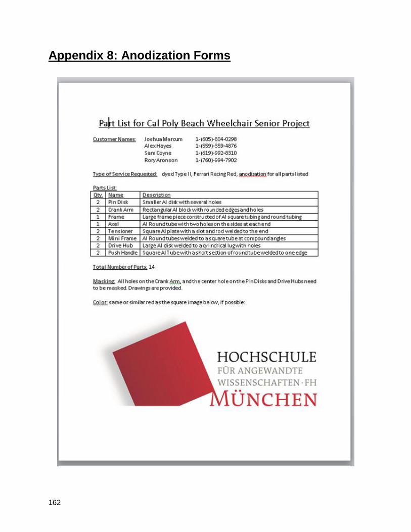
162
Appendix 8: Anodization Forms

163
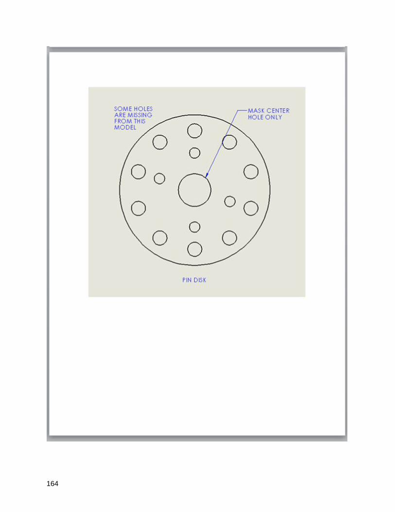
164
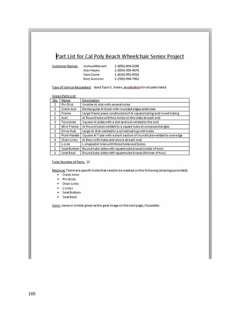
165
166
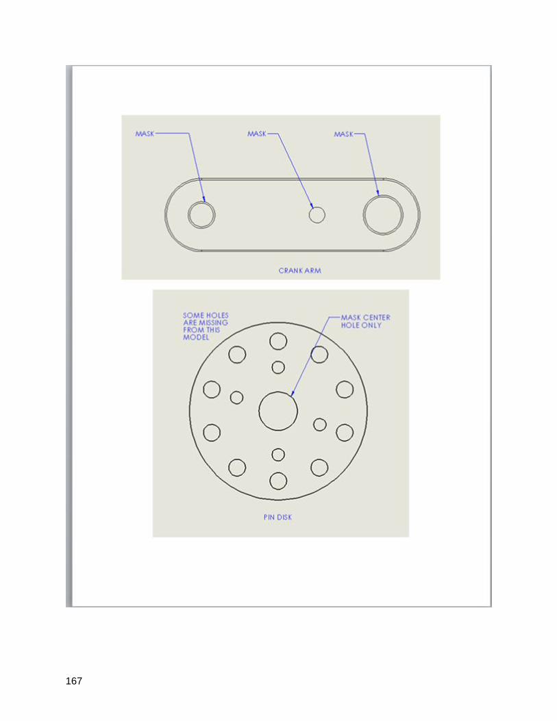
167
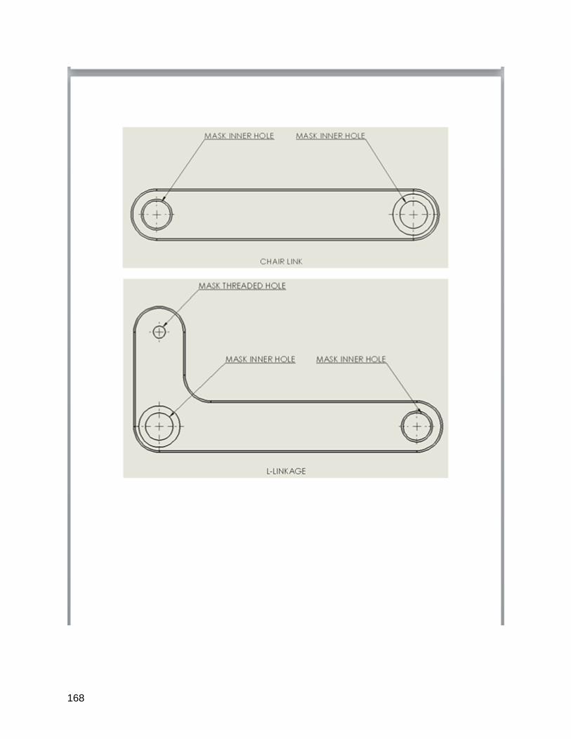
168
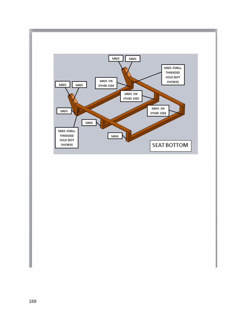
169
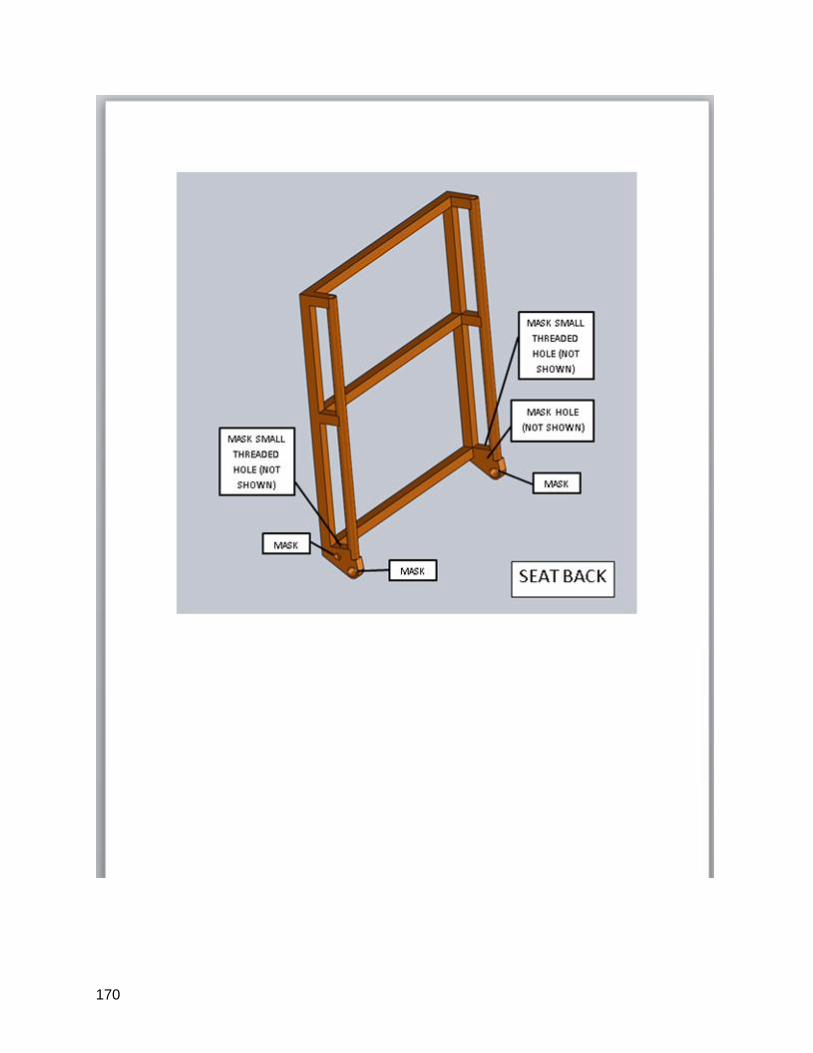
170
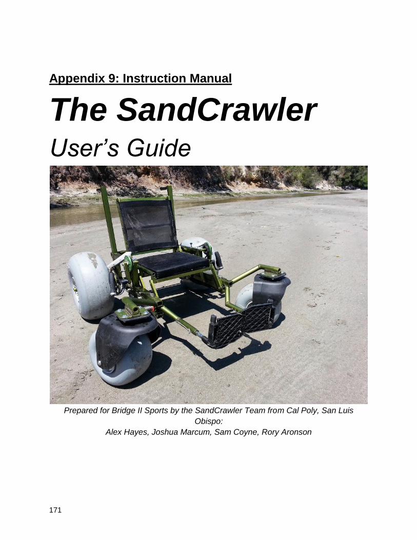
171
Appendix 9: Instruction Manual
The SandCrawler
User’s Guide
Prepared for Bridge II Sports by the SandCrawler Team from Cal Poly, San Luis
Obispo:
Alex Hayes, Joshua Marcum, Sam Coyne, Rory Aronson
172
The Fine Print
Congratulations on choosing the finest beach wheelchair known to humankind! We
hope you enjoy your beach experience. Before you use the wheelchair, here are some
things we insist you understand.
1. This wheelchair is a prototype. There are inherent
risks in a premarket product like this that you must
accept if you are to use it.
2. There are pinch points in numerous spots especially
between the chair and frame and under the belt.
Exercise caution.
3. If you will be entering the water, a guardian must be
present and a lifejacket must be worn.
4. Lower the seat and remove the seatbelt before
entering the water.
5. You must have fun while using this wheelchair.
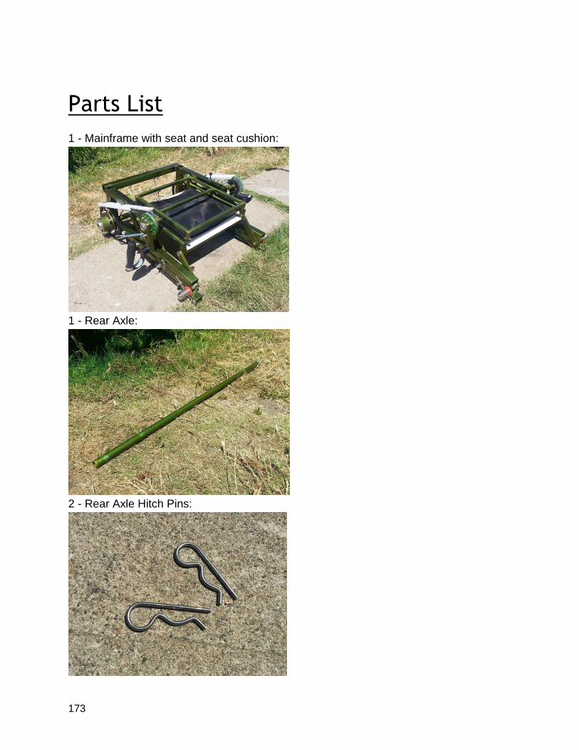
173
Parts List
1 - Mainframe with seat and seat cushion:
1 - Rear Axle:
2 - Rear Axle Hitch Pins:
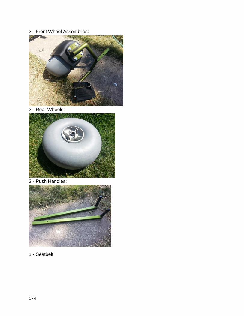
174
2 - Front Wheel Assemblies:
2 - Rear Wheels:
2 - Push Handles:
1 - Seatbelt
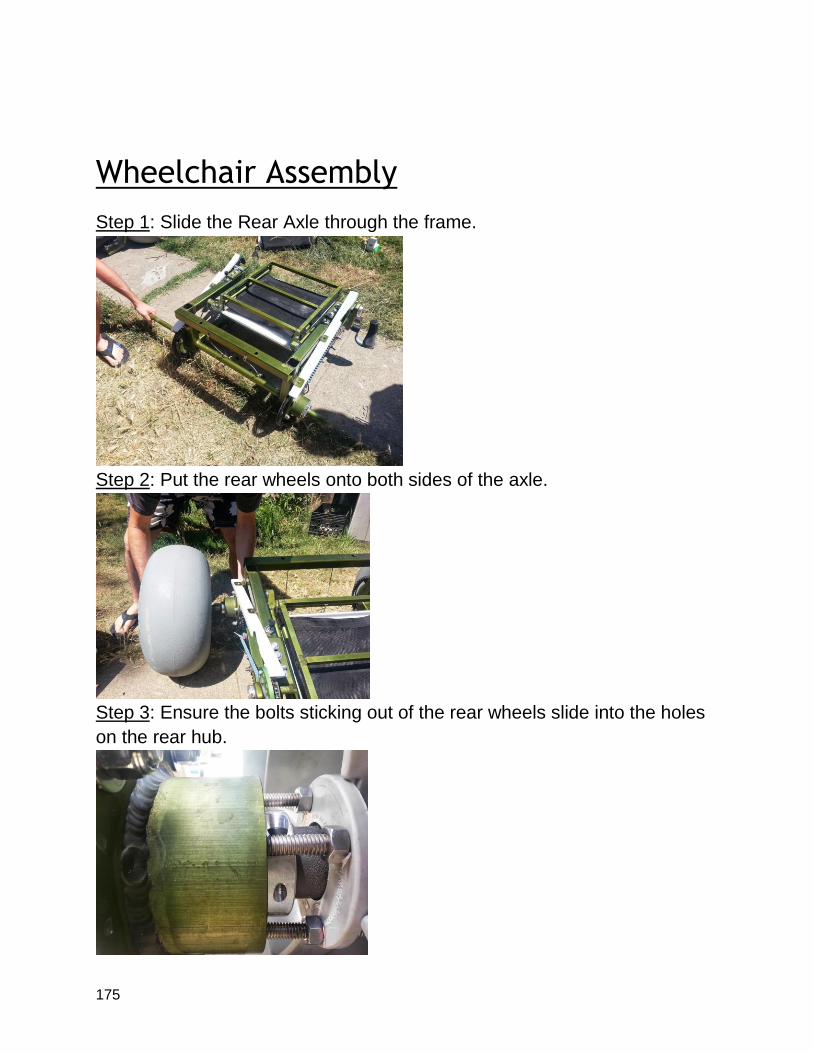
175
Wheelchair Assembly
Step 1: Slide the Rear Axle through the frame.
Step 2: Put the rear wheels onto both sides of the axle.
Step 3: Ensure the bolts sticking out of the rear wheels slide into the holes
on the rear hub.
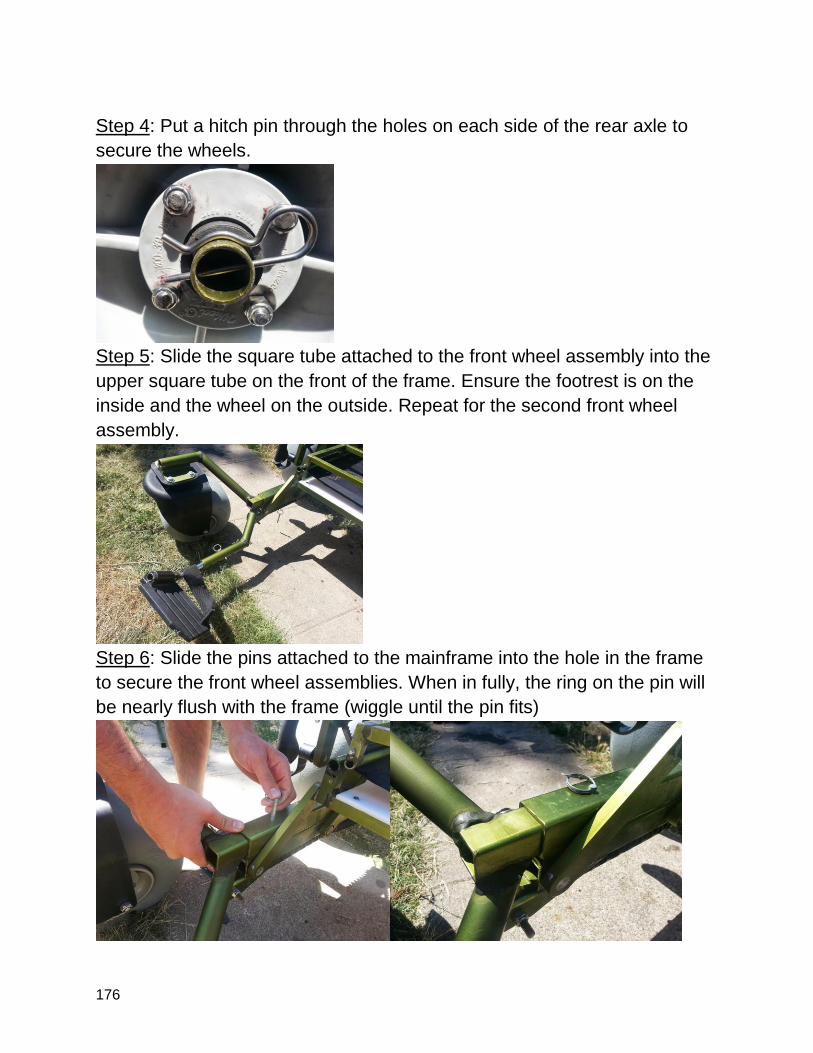
176
Step 4: Put a hitch pin through the holes on each side of the rear axle to
secure the wheels.
Step 5: Slide the square tube attached to the front wheel assembly into the
upper square tube on the front of the frame. Ensure the footrest is on the
inside and the wheel on the outside. Repeat for the second front wheel
assembly.
Step 6: Slide the pins attached to the mainframe into the hole in the frame
to secure the front wheel assemblies. When in fully, the ring on the pin will
be nearly flush with the frame (wiggle until the pin fits)
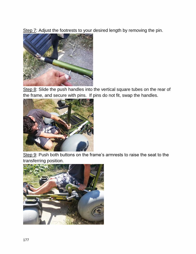
177
Step 7: Adjust the footrests to your desired length by removing the pin.
Step 8: Slide the push handles into the vertical square tubes on the rear of
the frame, and secure with pins. If pins do not fit, swap the handles.
Step 9: Push both buttons on the frame’s armrests to raise the seat to the
transferring position.
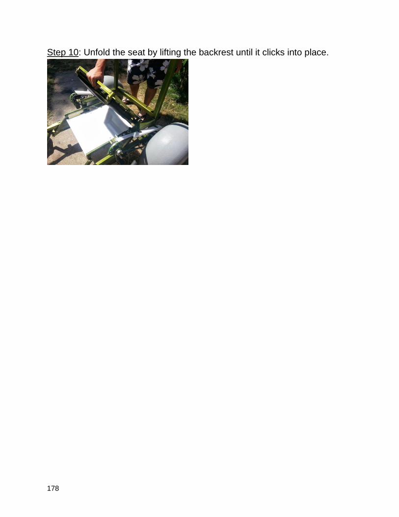
178
Step 10: Unfold the seat by lifting the backrest until it clicks into place.
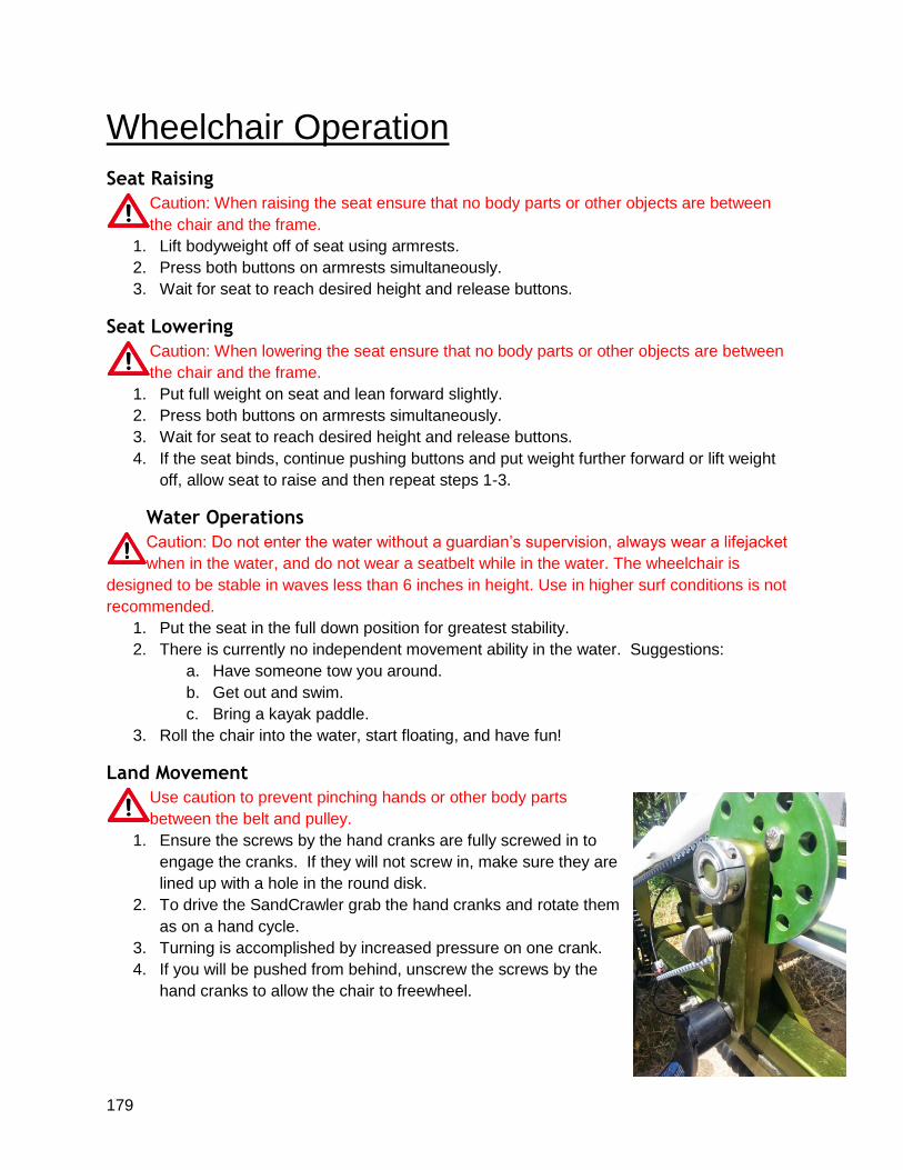
179
Wheelchair Operation
Seat Raising Caution: When raising the seat ensure that no body parts or other objects are between
the chair and the frame.
1. Lift bodyweight off of seat using armrests.
2. Press both buttons on armrests simultaneously.
3. Wait for seat to reach desired height and release buttons.
Seat Lowering Caution: When lowering the seat ensure that no body parts or other objects are between
the chair and the frame.
1. Put full weight on seat and lean forward slightly.
2. Press both buttons on armrests simultaneously.
3. Wait for seat to reach desired height and release buttons.
4. If the seat binds, continue pushing buttons and put weight further forward or lift weight
off, allow seat to raise and then repeat steps 1-3.
Water Operations Caution: Do not enter the water without a guardian’s supervision, always wear a lifejacket
when in the water, and do not wear a seatbelt while in the water. The wheelchair is
designed to be stable in waves less than 6 inches in height. Use in higher surf conditions is not
recommended.
1. Put the seat in the full down position for greatest stability.
2. There is currently no independent movement ability in the water. Suggestions:
a. Have someone tow you around.
b. Get out and swim.
c. Bring a kayak paddle.
3. Roll the chair into the water, start floating, and have fun!
Land Movement Use caution to prevent pinching hands or other body parts
between the belt and pulley.
1. Ensure the screws by the hand cranks are fully screwed in to
engage the cranks. If they will not screw in, make sure they are
lined up with a hole in the round disk.
2. To drive the SandCrawler grab the hand cranks and rotate them
as on a hand cycle.
3. Turning is accomplished by increased pressure on one crank.
4. If you will be pushed from behind, unscrew the screws by the
hand cranks to allow the chair to freewheel.
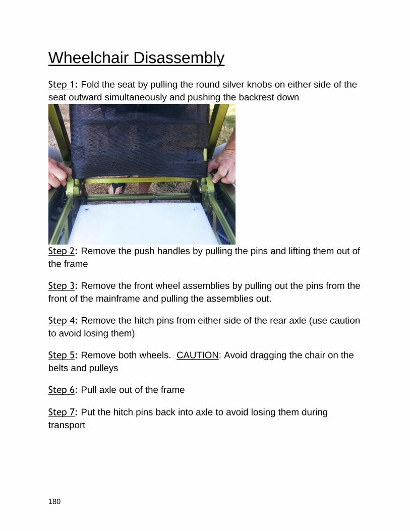
180
Wheelchair Disassembly
Step 1: Fold the seat by pulling the round silver knobs on either side of the
seat outward simultaneously and pushing the backrest down
Step 2: Remove the push handles by pulling the pins and lifting them out of
the frame
Step 3: Remove the front wheel assemblies by pulling out the pins from the
front of the mainframe and pulling the assemblies out.
Step 4: Remove the hitch pins from either side of the rear axle (use caution
to avoid losing them)
Step 5: Remove both wheels. CAUTION: Avoid dragging the chair on the
belts and pulleys
Step 6: Pull axle out of the frame
Step 7: Put the hitch pins back into axle to avoid losing them during
transport