Embed Size (px)
Citation preview

Beacon II Smart ControllerInstallation & OperationManual
Part No. 25000601
Replaces H-IM-80D (02/04)
Features ..................................................................... 2-3Installation ................................................................ 4Wiring ........................................................................ 5Power Supply ............................................................ 6Initialization of Beacon II Smart Controller ............ 7Button Functions ...................................................... 7Programming Beacon II Smart Controller .............. 8Monitoring Beacon II Smart Controller................... 9Locking Beacon II Smart Controller ........................ 10Error Codes ................................................................ 10Wiring Errors ............................................................. 11Alarm Codes .............................................................. 11Alarm Buzzer ............................................................. 12Data Logging ............................................................ 12Smart Defrost ............................................................ 13PC & Modem Access .................................................. 14System Defaults ........................................................ 15Wiring Diagrams ....................................................... 16-19
Table of Contents
H-IM-80D July 2011

2
Beacon II Smart Controller Features
© 2011, Heatcraft Refrigeration Products LLC
The Beacon II Smart Controller performs all the standard Beacon II functions with the additional benefit of:
a) Remote mounting for easy access
b) Remote monitoring and programming
c) Controlling a maximum of four completely separate systems
d) Logging data
e) Smart Defrost
f) Access via PC or modem
g) Has buzzer to signal alarms
h) Locking keypad
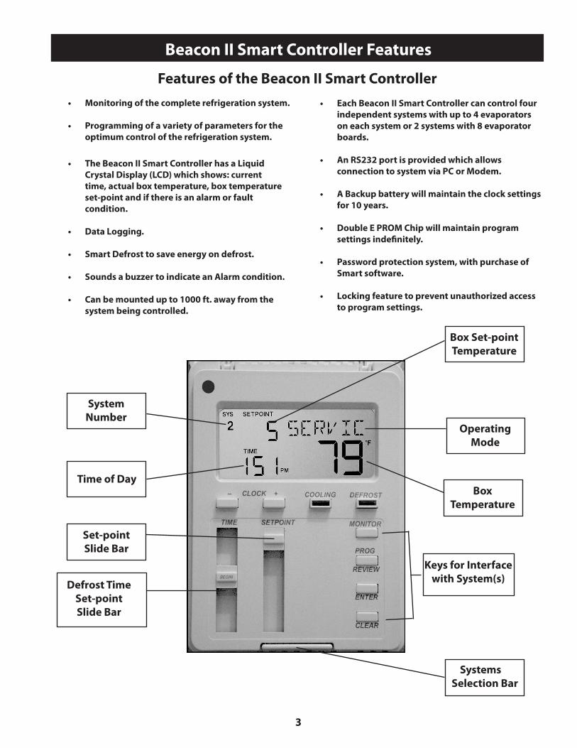
Beacon II Smart Controller allows complete monitoring and programming of the system.The Controller display has the following buttons: COOLING, DEFROST, PROG REVIEW, MONITOR, ENTER, CLEAR, SETPOINT AND TIME.
The normal LCD display will show the programmed box set-point temperature. actual box temperature, the current time of day and the mode (i.e. COOL, DEFROST or OFF). When multiple systems are being controlled, the system number (i.e. SYS 1, SYS 2, SYS 3, SYS 4) will also be displayed on the LCD.
Operational LimitsVoltage Range 18 VAC to 30 VACSurrounding Ambient Temp. Range 40°F to 100°FRelative Humidity 60% to MaximumControlling Box Temperature Range -30°F to 70°FBox Temperature Differential 2°F
Do not mount the Smart Controller where it will experience heavy vibration, such as near a Walk-in Box door.
3
Box Set-pointTemperature
OperatingMode
BoxTemperature
Systems Selection Bar
SystemNumber
Time of Day
Set-pointSlide Bar
Beacon II Smart Controller Features
• Monitoring of the complete refrigeration system.
• Programming of a variety of parameters for the optimum control of the refrigeration system.
• The Beacon II Smart Controller has a Liquid Crystal Display (LCD) which shows: current time, actual box temperature, box temperature set-point and if there is an alarm or fault condition.
• Data Logging.
• Smart Defrost to save energy on defrost.
• Sounds a buzzer to indicate an Alarm condition.
• Can be mounted up to 1000 ft. away from the system being controlled.
Features of the Beacon II Smart Controller
• Each Beacon II Smart Controller can control four independent systems with up to 4 evaporators on each system or 2 systems with 8 evaporator boards. • An RS232 port is provided which allows connection to system via PC or Modem.
• A Backup battery will maintain the clock settings for 10 years.
• Double E PROM Chip will maintain program settings indefinitely.
• Password protection system, with purchase of Smart software. • Locking feature to prevent unauthorized access to program settings.
Defrost TimeSet-pointSlide Bar
Keys for Interface with System(s)

4
TerminalStrip
RS232Connector
Installation
Alarm Contact
Ground Terminal
INSTALLATION
The Beacon II Smart Controller should be installed in a location where the large Liquid Crystal Display (LCD) can be viewed easily, yet is secure and vibration free. Because of the LCD screen, the Beacon II Smart Controller should not be mounted where it will experience temperatures below 40°F or above 100°F.
A terminal strip for wiring connections is located on the base of the Beacon II Smart Controller. To access this terminal strip, pull both halves of the Beacon II Smart Controller housing apart, while holding top near LCD display. Mounting holes are located in the plastic base.
Beacon II Smart Controller Base

5
Wiring
M = Master Evaporator S = Slave Evaporator CU = Condensing unit
SYSTEM 1 SYSTEM 2 SYSTEM 3
SYSTEM 4
WIRING All 24 volt wiring must be run separate from the line voltage wiring.
All low voltage wiring must be 18 gauge minimum and must be run separate from high voltage wiring. The maximum distance from the Beacon II Smart Controller to the master evaporator is 1000 ft.
The terminal strip in the Beacon II Smart Controller is labeled similarly to that of the Beacon II boards. Connect the corresponding terminals to those on the Beacon II board.
For single Refrigeration system:
Connect MULTI OUT 1 from the Beacon II Smart Controller to the MULTI IN on the Beacon II board on the Evaporator. Then connect MULTI IN 1 from the Beacon II Smart Controller to the MULTI OUT on the Beacon board on the evaporator. See typical wiring diagram at the back of these instructions.
On systems with multiple evaporators, the Beacon II Smart Controller must be wired to the master evaporator first. DO NOT disconnect the room sensor from any of the evaporators.
SINGLE SYSTEM CONNECTION
M = Master Evaporator S = Slave Evaporator CU = Condensing unit
For MULTIPLE independent refrigeration systems:
For the first system, connect MULTI OUT 1 from the Beacon II Smart Controller to the MULTI IN on the Beacon II board on the evaporator in this first system. Then connect MULTI IN 1 from the Beacon II Smart Controller to the MULTI OUT on the Beacon II board on the evaporator on this first system. DO NOT disconnect the room sensor from any of the evaporators. See typical wiring diagram at the back of these instructions.
For the second system, connect MULTI OUT 2 from the Beacon II Smart Controller to the MULTI IN on the Beacon II board on the evaporator in this second system. Then connect MULTI IN 2 from the Beacon II Smart Controller to the MULTI OUT on the Beacon II board on the evaporator on this second system. See typical wiring diagram at the back of these instructions.
On systems with multiple evaporators the Beacon II Smart Controller must be wired to the master evaporator first. DO NOT disconnect the Room sensor from any of the evaporators.
DO NOT CONNECT 24V & C BETWEEN EVAPORATORS.
The Beacon II Smart Controller and the evaporators are then connected in a daisy–chain fashion. (See the wiring diagrams in the back of this manual)
A minimum 18 gauge wire should be used. All low voltage wiring must be run separate from high voltage wiring.
MULTIPLE SYSTEM CONNECTION
6
Power Supply
POWER SUPPLY
The Beacon II Smart Controller 24 V power should come from one of two sources:
1. When the RS-232 port on the Smart Controller is NOT used: • Power typically comes from one evaporator in the Beacon II system. 24V and COM connections should be wired to the Beacon II board. • The evaporator power supply should floating (not grounded). The Beacon II evaporator board is grounded through its mounting screws. • The grounding terminal on the Smart Smart Controller should be connected to a good ground - typically in the evaporator electrical panel.
2. When the RS-232 port on the Smart Controller IS connected to a device:
• A dedicated 24V power supply must be used, separate from the Beacon II board(s) power supply. 24V and COM connections should be wired to this power supply. Typical power supply would be a 24VAC universal Plug-in Power Source with a minimum current rating of 300mA. • The power supply should be floating (not grounded). • The grounding terminal on the Smart Controller should be connected to a good ground - typically in the evaporator electrical panel.
If the Smart Controller LCD displays all “88888,” this indicates that the power supply is below 18VAC. When this occurs, the connected Beacon II components will power down and shut off. When the power supply is corrected to 24VAC, the system will restart after a 4 minute hold-off period and resume normal operation. The Smart Controller display will then be normal.
If a power interruption occurs to the Smart Controller, the LCD screen will go blank. Theconnected Beacon II systems will continue to operate and maintain box temperature provided their power supply is not interrupted.
7
Initialization of Beacon II Smart Controller
INITIALIZATION of BEACON II SMART CONTROLLER
When power is first applied to the Beacon II Smart Controller, it checks the configuration of the system to which it is connected and stores this in its memory. Beacon II Smart Controller checks how many condensing units there are and how many evaporators are connected to each condensing unit. The order in which the units are wired from the multi-out of the Beacon II Smart Controller determines the unit ID (UNI-4) assigned by the Beacon II Smart Controller. This is called initialization. Whenever a system is added, removed or modified (changing the number of evaporators on a condensing unit), while connected to the Beacon II Smart Controller, it must be re-initialized.
Place all systems in the service mode before initializing the Beacon II Smart Controller. Make sure all wiring changes to the system and the Beacon II Smart Controller are complete and accurate before initializing the Beacon II Smart Controller. Each SLAVE Evaporator must also be programmed as a SLAVE BEFORE the system is initialized. The “SLA” setpoint must be set from the board programming. It cannot be done from the Beacon II Smart Controller.
To initialize the Beacon II Smart Controller
• Press and Hold both the ENTER and CLEAR buttons until the LCD displays “EEROM?” • Release the ENTER and CLEAR buttons quickly, then press the ENTER button • The LCD will display “WAIT” • If unsuccessful “no chg” will be displayed
It may take up to 2 minutes to complete the initialization of the system after which the normal LCD screen will appear.
BUTTON FUNCTIONS
• SYSTEM SELECTION BAR: If two or more systems are being controlled from the Beacon II Smart Controller, this bar allows switching between systems. The display will show the SYS number and all parameters related to that system. The cover plate of Beacon II Smart Controller, when pushed will also change the display between systems.
• CLOCK (+ -) This is used to set the time of day on the display. • Depress the “+” button to move the clock forward • Depress the “-” button to move the clock backward • When in PROG Mode, these are used to step through values for setting superheat etc. for each evaporator of the system(s) attached to the Beacon II Smart Controller and for different defrost start time periods.
• COOLING: Depressing this button will start the system in the cooling cycle immediately (The 4 minutes “Hold Off” is bypassed). This button will illuminate to indicate that the Cooling function is “ON”. System operation will be as described under REFRIGERATION MODE in the Beacon II installation manual.
Pressing the COOLING button while the system is cooling, and the button illuminated, will pumpdown the system and turn it off.
• DEFROST: Depressing this button will force the system into defrost immediately (The “Hold Off/Hold On” times are bypassed). This button will illuminate to indicate that the Defrost function is “ON”. When in Defrost, pressing this button a second time will end defrost.
• MONITOR: Depressing the MONITOR button will display the setpoints shown on page 9.
If one Beacon II Smart Controller is controlling two or more independent systems, you must press the SELECTION BAR to display information on the system you want to monitor. If multiple evaporators are connected to the system displayed, you must press the “+” or “–” buttons to display information on the evaporator you want to monitor.
• PROG REVIEW: This button allows stepping through each of the setpoints for initial setup and to make changes.
If one Beacon II Smart Controller is controlling two or more independent systems, you must press the SELECTION BAR to display information on the system you want to make program changes. If multiple evaporators are connected to the system displayed, you must press the “+” or “–” buttons to display information on the evaporator you want to monitor.
• CLEAR: Used to clear incorrect entries while programming or to return to the System display when monitoring.
• TIME: Slide-bar is used to set the thermostat clock for Defrost times.
• SETPOINT: Slide-bar is used to change settings while programming.
• ENTER: To enter new settings into the program. NOTE: Settings are recorded in memory even if power fails.
8
Programming Beacon II Smart Controller
PROGRAMMING BEACON II SMART CONTROLLER
To make a change, press the PROG REVIEW button until the setpoint item that needs to be changed is displayed. The SETPOINT Slide-bar is then used to change to the desired new setting. When the new desired setting is displayed, press the “ENTER” button. The new setting is now programmed into the Beacon II Smart Controller memory.
Press the PROG REVIEW button and follow the steps below (to back up one step during programming, while pressing the “MONITOR” button, press the “PROG REVIEW” button):
• DEFTYP – ELE or AIR: Select for Electric Defrost or Air Defrost then press “ENTER”. This selection will automatically set the defaults for Air and Electric Defrost. Important: This will set the refrigerant type to R22 for Air and R404A for Electric. You must change to the refrigerant you are using in your application if these are incorrect.
• REFTYP – 22, 404, 507. Use “SETPOINT” slide-bar to display desired value, then press “ENTER.”
• BOXTMP – Box Temp: -30° F to 70° F. Use “SETPOINT” slide-bar to get desired temperature, then press “ENTER.”
• SUPRHT – Superheat: 4 to 20 ° F. Use “SETPOINT” slide-bar to select desired superheat temperature, then press “ENTER.” If multiple evaporators are connected, use the “+” button to set other evaporators on this system.
• SMT DFT : Smart Defrost: On/Off. Use “SETPOINT” slide-bar to turn it ON or OFF, then press “ENTER” - (for version 1.2. When Smart Defrost is turned on, 8 defrost periods per day will automatically be programmed. These will be at 12:00 am, 3:00 am, 6:00 am, 9:00 am, 12:00 pm, 3:00 pm, 6:00 pm, and 9:00 pm. Also, the defrost fail safe time will be set to 60 minutes, and the defrost termination temperature will be set to 55°F. The user can change these as needed for the application).
• DEF ST - Defrost Start time: Up to 12 settings per day (For dF 1, use the “TIME” slide-bar to select first defrost time, then press “ENTER”. Use + button to scroll to next defrost period, dF 2, use “TIME” slide-bar to select second defrost time and press “ENTER”. Repeat steps for each required defrost period). If defrost times are not programmed the system will use the defaults: Electric Defrost - four per day at 4:00 AM, 10:00 PM, 4:00 PM, 10:00 AM. Air Defrost - two per day at 9:00 AM, 9:00 PM.
• DEFSAF – Defrost Fail Safe Time: 10 to 200 minutes. When this time has elapsed, the defrost cycle will end, even if the programmed Defrost Termination temperature was not achieved. Use “SETPOINT” slide-bar to select desired time, then press “ENTER”.
• DEFTMP – Defrost Termination Temperature: 40 to 100° F. Use “SETPOINT” slide-bar to select desired temperature, then press “ENTER”. If multiple evaporators are connected, use the “+” button to set other evaporators xon this system.
• ALR HI – Alarm High Temperature. -40 to 90° F. Use “SETPOINT” slide-bar to select desired temperature, then press “ENTER”.
• ALR LO – Alarm Low Temperature -40 to 90° F. Use “SETPOINT” slide-bar to select desired temperature, then press “ENTER”.
• ALRMIN – Alarm Time, in minutes. Condition must exceed before alarm is indicated: 2 to 120 minutes. Use “SETPOINT” slide-bar to select desired time, then press “ENTER”.
• ° F / ° C – ° F or ° C. Use “SETPOINT” slide-bar to select then press “ENTER”.
• 12/24H – Clock: 12H is for standard time. 24H is for international time. Use “SETPOINT” slide-bar to select, then press “ENTER”.
• TEST : OFF or ON: Puts all evaporators in TEST mode. Use with Caution. This will cycle each output at 10 second intervals. Use “SETPOINT” slide-bar to select, then press “ENTER”. Return to “OFF” and then press “ENTER” to end the test.
• SERVIC – ON or OFF: When placed in the ON mode this will pump the system down and shut it off. The system will not restart until SERVIC is placed back in the OFF mode.
When multiple evaporators are connected as master/ slave, depressing the + or - button will display information specific to each evaporator. Units in a master/slave connection are numbered 1 through 4. The first evaporator connected to the BEACON II SMART CONTROLLER MULTI-OUT Terminals is Evaporator # 1.

9
Monitoring With Beacon II Smart Controller
MONITORING with BEACON II SMART CONTROLLER
The monitoring function can be used to monitor live system data. The information displayed, such as super-heat, is the actual superheat of the system as it is changing.
Press the MONITOR button and follow the steps below (to back up one step during monitoring, while pressing the “PROG REVIEW” button, press the “MONITOR” button):
• SUPRHT – Superheat (use + button to check super- heat of other evaporators, if Master/slave)
• EXVSET - Expansion valve step setting (Stepper Motor setting 0 to 255 steps: use + button to check other evaporators if Master/slave)
• SUCTMP – Evaporator Suction temperature (Measured by the Suction Sensor)
• SSVTMP – Saturated Suction temperature at the Evaporator (Determined by Suction Transducer)
• SUCPRE – Evaporator Suction Pressure (Measured by Suction Transducer)
• OD TMP – Actual outdoor ambient temperature (Measured at the Condensing Unit)
• DEFTMP – Evaporator coil temperature (Used to terminate defrost)
• DEFTIM - Defrost Time: Length of last defrost
• CMPCYC - Comp Cycles: No of Compressor Cycles since 12:00 midnight
• CMPRUN - Comp run time (Measured since 12:00 midnight)
• SPRTMP – Spare sensor temperature input
• VERSON – Software Version: For each controller (use “+” button to check other evaporators, if Master/ slave)
• VERSON - Software Version: for Beacon II Smart Controller
When multiple evaporators are connected as master/slave depressing the + or - button will display information specific to each evaporator. Units in a master/slave connection are numbered 1 through 4.The first evaporator connected to the BEACON II SMART CONTROLLER MULTI-OUT Terminals is Evaporator # 1 and must be a “master” board.
MODBUS OFF By default MODBUS OFF should show on the Smart controller. The new Smart controller has two ports: RS232 and RS485. MODBUS communication is via RS485, and Smart II software for PC is via RS232. The hardware interface is available for the MODBUS commu-nication, but the current software version does not have MODBUS protocol.

10
Locking Beacon II Smart Controller & Error Codes
LOCKING BEACON II SMART CONTROLLER
BEACON II SMART CONTROLLER is lockable to prevent programmed settings changes by unauthorized personnel. When the Controller is Locked, all the Buttons, except for the Monitor and Prog Review Buttons, are disabled.
To LOCK the settings, do the following:• Press “PROG REVIEW” button.• Press and hold “MONITOR” button• While holding “MONITOR” button,
press “ENTER” button.• The LCD will display LOCK
This will prevent unauthorized persons from changing any settings for system displayed.To UNLOCK the Controller, repeat these steps. LCD will display “UNLOCK.” Note: Each system must be locked or unlocked separately.
ERROR CODES
• *BXSEN - Room temperature sensor shorted, open or not installed
• *DFSEN - Defrost temperature sensor shorted, open or not installed
• *STSEN - Suction Temperature sensor shorted, open or not installed
• *SPSEN - Suction pressure transducer shorted, open or not installed
• *ODSEN - Outdoor temperature sensor shorted
• *SUPLO - Superheat too low
• *SHTDN - Compressor shutdown (High or low refrigerant pressure or low oil pressure)
The error code will flash alternately with the normal display information. When the error condition is corrected, the error code will no longer be displayed and only the normal information will be displayed.
*All errors for all units connected to the Beacon II Smart Controller will be displayed with an appropriate indicator for the unit experiencing the error. The individual boards will also display the errors.

11
Wiring Error & Alarm Codes
WIRING ERROR
If the Beacon II Smart Controller LCD displays “+COMM+,” this indicates that there is an error in the communication wiring or that the wiring is broken or disconnected. Occurrence of this error on the connected unit will indicate which wires are faulty.
The communication wiring is the MULTI IN and MULTI OUT connections. Check to make sure the OUT is connected to IN. Never connect OUT to OUT or IN to IN.
ALARM CODES
• *BOXHI : Box temperature too high
• *BOXLO : Box temperature too low
• *STRUP :System Start-up failure (Compressor pumps down and tries to restart after
4 minutes.)
• *INFLT : Input fault (Box Temp., Suction Temp., Pressure Transducer open or not installed)
• Power failure
When an ALARM condition occurs, the Beacon II Smart Controller will display “CALL FOR SERVICE”, the ALARM code, the SYSTEM Number and will sound an internal buzzer along with the closure of alarm contacts on controller.
The alarm code will flash alternately with the normal display information. When the alarm condition is corrected, the alarm code will no longer be displayed and only the normal information will be displayed.
The system will pumpdown and cycle off and willnot restart until the fault is cleared for the following conditions: • Suction sensor shorted, open or not installed • Room temperature sensor shorted, open or not installed on master • Pressure Transducer open or not installed
The system will pumpdown, cycle off and try to restart for three consecutive times. Each try will be after the 4 minutes “Hold Off” period, for the following fault conditions. • Oil pressure • High pressure or low pressure cutout (or any other compressor safeties)
After the fourth try, the alarm contacts will be closed and an alarm message displayed on the LCD screen. To clear this condition, the system should be cycled through the “Service” mode after correction is complete. On Multiple systems the alarm contacts on each of the Master Evaporators will also announce alarms for that system. Alarms on slave evaporators will only occur for input fault and power failure.
12
Alarm Buzzer & Data Logging
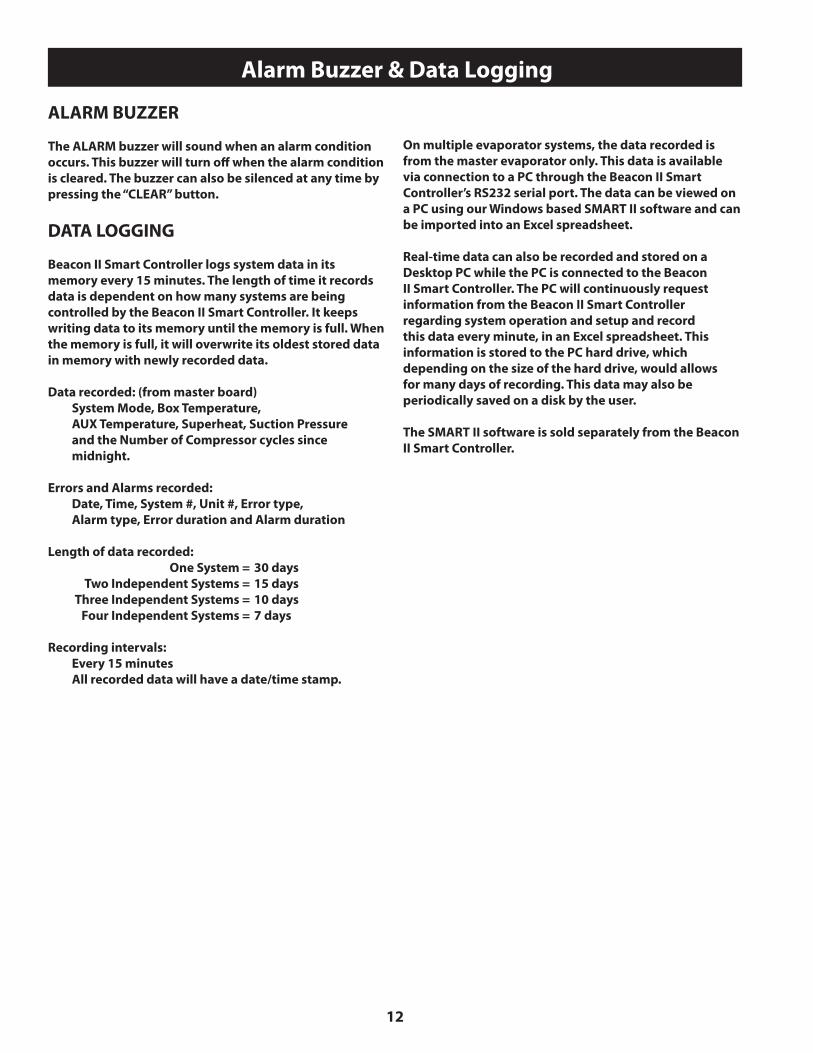
ALARM BUZZER
The ALARM buzzer will sound when an alarm condition occurs. This buzzer will turn off when the alarm condition is cleared. The buzzer can also be silenced at any time by pressing the “CLEAR” button.
DATA LOGGING
Beacon II Smart Controller logs system data in its memory every 15 minutes. The length of time it records data is dependent on how many systems are being controlled by the Beacon II Smart Controller. It keeps writing data to its memory until the memory is full. When the memory is full, it will overwrite its oldest stored data in memory with newly recorded data.
Data recorded: (from master board) System Mode, Box Temperature, AUX Temperature, Superheat, Suction Pressure and the Number of Compressor cycles since midnight.
Errors and Alarms recorded: Date, Time, System #, Unit #, Error type, Alarm type, Error duration and Alarm duration
Length of data recorded: One System = 30 days Two Independent Systems = 15 days Three Independent Systems = 10 days Four Independent Systems = 7 days
Recording intervals: Every 15 minutes All recorded data will have a date/time stamp.
On multiple evaporator systems, the data recorded is from the master evaporator only. This data is available via connection to a PC through the Beacon II Smart Controller’s RS232 serial port. The data can be viewed on a PC using our Windows based SMART II software and can be imported into an Excel spreadsheet.
Real-time data can also be recorded and stored on a Desktop PC while the PC is connected to the Beacon II Smart Controller. The PC will continuously request information from the Beacon II Smart Controller regarding system operation and setup and record this data every minute, in an Excel spreadsheet. This information is stored to the PC hard drive, which depending on the size of the hard drive, would allows for many days of recording. This data may also be periodically saved on a disk by the user.
The SMART II software is sold separately from the Beacon II Smart Controller.
13
Smart Defrost
SMART DEFROST
The Beacon II Smart Controller continuously monitors the system performance to determine the need for defrost. It uses a variety of data such as the outdoor ambient and box temperature in it’s decision making process.
Activating Smart Defrost: After your system has been running for a week or two with normal defrost operation and the system has operated normally with no problems, you may consider activating Smart Defrost.
You must program multiple defrost times into the Beacon II Smart Controller to provide flexibility for the system to defrost the coil properly. Smart Defrost will only allow the system to defrost at a programmed defrost time. The system will not defrost in between programmed defrost times. Hence, we recommend that a minimum of 8 defrost periods be programmed when Smart Defrost is turned on. The system will have the potential to defrost eight times per day to keep the coil clear and to allow the system to operate at optimum condition.
To activate Smart Defrost, press the “PROG REVIEW” button until “SMT DFT” is displayed. (Also, it is recommended that the defrost fail-safe time be increased to 60 minutes).
Move the “SETPOINT” slide-bar to “ON” then press “ENTER”. Press “CLEAR” to return to the main screen.
When Smart Defrost is turned on, 8 defrost periods per day will automatically be programmed. These will be at 12:00 am, 3:00 am, 6:00 am, 9:00 am, 12:00 pm, 3:00 pm, 6:00 pm, and 9:00 pm. Also, the defrost fail safe time will be set to 60 minutes, and the defrost termination temperature will be set to 55°F. The user can change these as needed for the application.
Deactivating Smart Defrost: To turn Smart Defrost off, move the “SETPOINT” slide bar to “OFF” then press “ENTER”. Press “CLEAR” to return to the main screen.

14
PC And Modem Access
™
Communications HubFor the connection of multiple Beacon II Smart Controllers to a single communication device (PC or modem).
Maximum configuration: • 4 Beacon II Smart Controllers™ connected to one Communications Hub (4 systems per Beacon II Smart Controller™ equals 16 systems with maximum of 64 evaporators)
PC & MODEM ACCESS
For access to the system from a PC directly or via a modem, the SMART II Software must be purchased and installed on your PC. See Beacon II Smart Control software instructions for recommended hardware requirements
Note: Special
• 16 Beacon II Smart Controllers™ connected to five Communications Hubs (4 systems per [Bea con II] Smart Controller™ equals 64 systems with maximum of 256 evaporators; Communications Hubs can only be cascaded once)
Note: Not compatible with Vantage™ Console
Parts ListPart Description HRP Part Number
*Beacon II Smart Controller 89704301Smart Controller Software Package** 89704101Beacon II Communications Hun 89708001
15
System Defaults
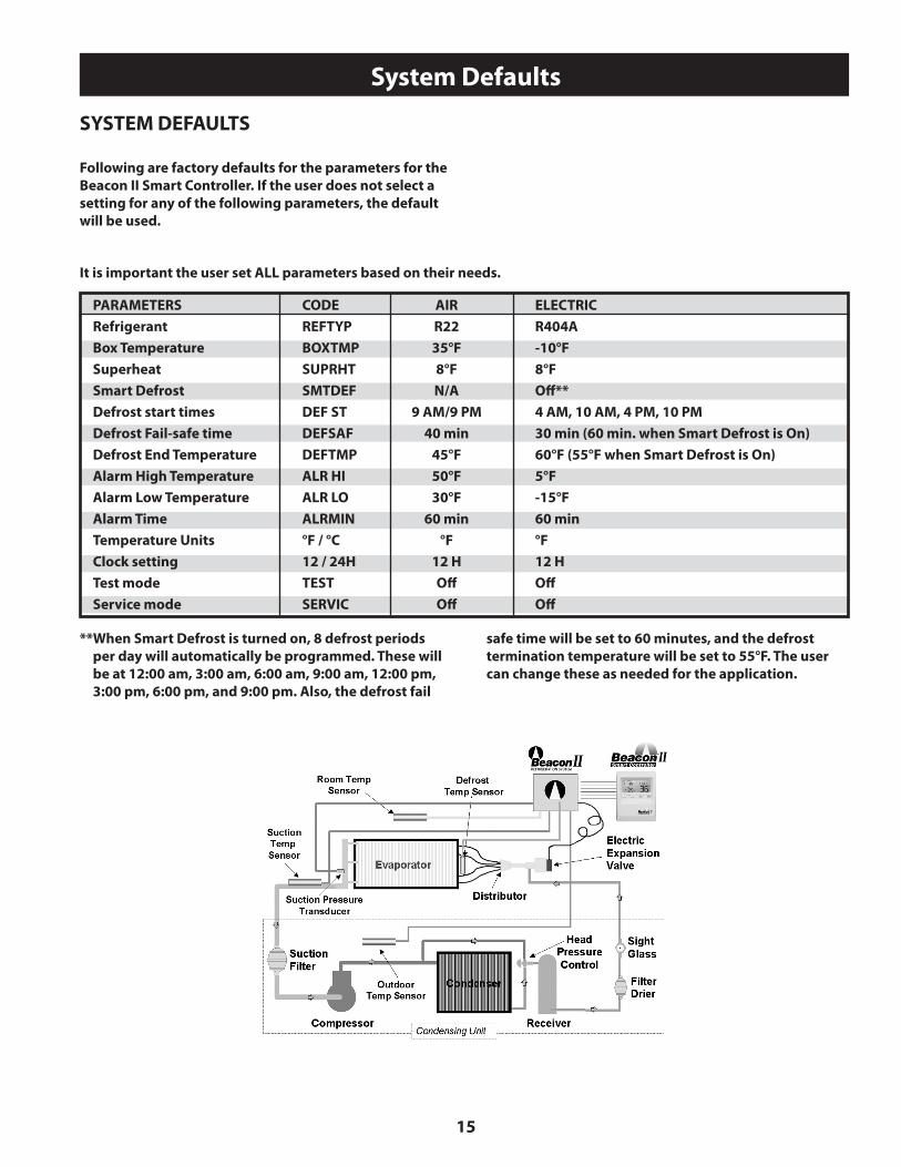
SYSTEM DEFAULTS
Following are factory defaults for the parameters for the Beacon II Smart Controller. If the user does not select a setting for any of the following parameters, the default will be used.
It is important the user set ALL parameters based on their needs.
PARAMETERS CODE AIR ELECTRIC Refrigerant REFTYP R22 R404A Box Temperature BOXTMP 35°F -10°F Superheat SUPRHT 8°F 8°F Smart Defrost SMTDEF N/A Off** Defrost start times DEF ST 9 AM/9 PM 4 AM, 10 AM, 4 PM, 10 PM Defrost Fail-safe time DEFSAF 40 min 30 min (60 min. when Smart Defrost is On) Defrost End Temperature DEFTMP 45°F 60°F (55°F when Smart Defrost is On) Alarm High Temperature ALR HI 50°F 5°F Alarm Low Temperature ALR LO 30°F -15°F Alarm Time ALRMIN 60 min 60 min Temperature Units °F / °C °F °F Clock setting 12 / 24H 12 H 12 H Test mode TEST Off Off Service mode SERVIC Off Off
**When Smart Defrost is turned on, 8 defrost periods per day will automatically be programmed. These will be at 12:00 am, 3:00 am, 6:00 am, 9:00 am, 12:00 pm, 3:00 pm, 6:00 pm, and 9:00 pm. Also, the defrost fail
safe time will be set to 60 minutes, and the defrost termination temperature will be set to 55°F. The user can change these as needed for the application.
16
Wiring Diagrams
HEATCRAFT PART NO. 29661601
COMP
SERVICE
COM
OUTDOORTEMP
MULTI OUT
MULTI IN
24V
C
SER
COMP
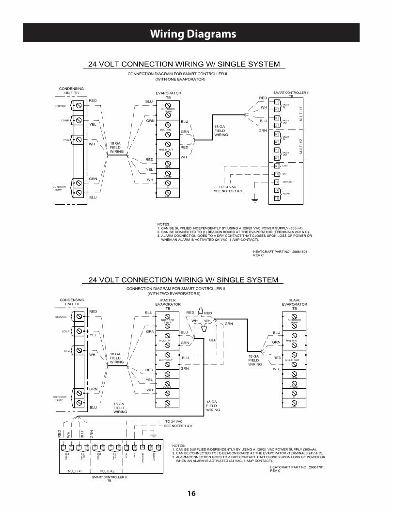
CONNECTION DIAGRAM FOR SMART CONTROLLER II
CONDENSINGUNIT TB EVAPORATOR
TB
24 VOLT CONNECTION WIRING W/ SINGLE SYSTEM
REV C
BLU
GRN
YEL
WH
18 GAFIELDWIRING
RED
BLU
GRN
WH
YEL
RED
(WITH ONE EVAPORATOR)
BLU
GRN
WH
RED
3
4
5
6
7
8
9
10
MULTIIN
MULTIOUT
COM
24V
ALARM
SMART CONTROLLER IITB
1
2
MULTIIN
MULTIOUT
11
12
MU
LTI #
1M
ULT
I #2
18 GAFIELDWIRING
RED
WH
GRN
BLU
NOTES:1. CAN BE SUPPLIED INDEPENDENTLY BY USING A 120/24 VAC POWER SUPPLY (300mA).2. CAN BE CONNECTED TO (1) BEACON BOARD AT THE EVAPORATOR (TERMINALS 24V & C).3. ALARM CONNECTION GOES TO A DRY CONTACT THAT CLOSES UPON LOSS OF POWER OR
WHEN AN ALARM IS ACTIVATED (24 VAC, 1 AMP CONTACT).
TO 24 VACSEE NOTES 1 & 2
13
GROUND
OUTDOORTEMP
HEATCRAFT PART NO. 29661701
COMP
SERVICE
COM
OUTDOORTEMP
MULTI OUT
MULTI IN
24V
C
SER
COMP
CONNECTION DIAGRAM FOR SMART CONTROLLER II
CONDENSINGUNIT TB
MASTEREVAPORATOR
TB
24 VOLT CONNECTION WIRING W/ SINGLE SYSTEM
REV C
BLU
GRN
YEL
WH
18 GAFIELDWIRING
RED
BLU
GRN
WH
YEL
RED
(WITH TWO EVAPORATORS)
BLU
GRN
18 GAFIELDWIRING
BLU
NOTES:1. CAN BE SUPPLIED INDEPENDENTLY BY USING A 120/24 VAC POWER SUPPLY (300mA).2. CAN BE CONNECTED TO (1) BEACON BOARD AT THE EVAPORATOR (TERMINALS 24V & C).3. ALARM CONNECTION GOES TO A DRY CONTACT THAT CLOSES UPON LOSS OF POWER OR
WHEN AN ALARM IS ACTIVATED (24 VAC, 1 AMP CONTACT).
TO 24 VACSEE NOTES 1 & 2
3 4 5 6 7 8 9 10
MU
LTI
IN
MU
LTI
OU
T
CO
M
24V
ALA
RM
1 2
MU
LTI
IN
MU
LTI
OU
T
11 12
MULTI #1 MULTI #2
RE
D
WH
GR
N
BLU
SMART CONTROLLER IITB
MULTI OUT
MULTI IN
24V
COMP
SLAVEEVAPORATOR
TB
WH
RED
GRN
BLU
GRN
RED
WH
RED
WH
18 GAFIELDWIRING
18 GAFIELDWIRING
GRN
BLU
13
GR
OU
ND
OUTDOORTEMP
C
SER
OUTDOORTEMP
17
Wiring Diagrams
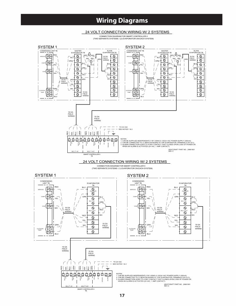
HEATCRAFT PART NO. 29661801REV C
NOTES:1. CAN BE SUPPLIED INDEPENDENTLY BY USING A 120/24 VAC POWER SUPPLY (300mA).2. CAN BE CONNECTED TO (1) BEACON BOARD AT THE EVAPORATOR (TERMINALS 24V & C).3. ALARM CONNECTION GOES TO A DRY CONTACT THAT CLOSES UPON LOSS OF POWER OR
WHEN AN ALARM IS ACTIVATED (24 VAC, 1 AMP CONTACT).
3 4 5 6 7 8 9 10
MU
LTI
IN
MU
LTI
OU
T
CO
M
24V
1 2
MU
LTI
IN
MU
LTI
OU
T
MULTI #1 MULTI #2
RE
D
WH
GR
N
BLU
SMART CONTROLLER IITB
18 GAFIELDWIRING
CONNECTION DIAGRAM FOR SMART CONTROLLER II
24 VOLT CONNECTION WIRING W/ 2 SYSTEMS
(TWO SEPARATE SYSTEMS / (2) EVAPORATOR ON EACH SYSTEM)
18 GAFIELDWIRING
RE
D
WH
GR
N
BLU
SYSTEM 2SYSTEM 1
COMP
SERVICE
COM
OUTDOOR
TEMP
CONDENSING UNIT TB MASTEREVAPORATOR TB
BLU
GRN
YEL
WH
18 GAFIELDWIRING
RED
BLU
GRN
WH
YEL
RED
BLU
GRN
18 GAFIELDWIRING
BLU
MULTI OUT
MULTI IN
24V
COMP
SLAVEEVAPORATOR TB
WH
RED
GRN
BLU
GRN
RED
WH
RED
WH
18 GAFIELDWIRING
MULTI OUT
MULTI IN
24V
C
COMP
SER
BLU
GRN
COMP
SERVICE
COM
OUTDOOR
TEMP
CONDENSING UNIT TB MASTEREVAPORATOR TB
BLU
GRN
YEL
WH
18 GAFIELDWIRING
RED
BLU
GRN
WH
YEL
RED
BLU
GRN
18 GAFIELDWIRING
BLU
MULTI OUT
MULTI IN
24V
COMP
SLAVEEVAPORATOR TB
WH
RED
GRN
BLU
GRN
RED
WH
RED
WH
18 GAFIELDWIRING
MULTI OUT
MULTI IN
24V
COMP
BLU
GRN
ALA
RM
11 12 13
GR
OU
ND
TO 24 VACSEE NOTES 1 & 2
OUTDOORTEMP
C
SER
OUTDOORTEMP
C
SER
OUTDOORTEMP
C
SER
OUTDOORTEMP
HEATCRAFT PART NO. 29661901
COMP
SERVICE
COM
OUTDOORTEMP
MULTI OUT
MULTI IN
24V
C
SER
COMP
CONDENSINGUNIT TB EVAPORATOR
TB
REV C
BLU
GRN
YEL
WH
18 GAFIELDWIRING
RED
BLU
GRN
WH
YEL
RED
NOTES:1. CAN BE SUPPLIED INDEPENDENTLY BY USING A 120/24 VAC POWER SUPPLY (300mA).2. CAN BE CONNECTED TO (1) BEACON BOARD AT THE EVAPORATOR (TERMINALS 24V & C).3. ALARM CONNECTION GOES TO A DRY CONTACT THAT CLOSES UPON LOSS OF POWER OR
WHEN AN ALARM IS ACTIVATED (24 VAC, 1 AMP CONTACT).
3 4 5 6 7 8 9 10
MU
LTI
IN
MU
LTI
OU
T
CO
M
24V
1 2
MU
LTI
IN
MU
LTI
OU
T
MULTI #1 MULTI #2
RE
D
WH
GR
N
BLU
SMART CONTROLLER IITB
BLU
GRN
RED
WH
18 GAFIELDWIRING
18 GAFIELDWIRING
CONNECTION DIAGRAM FOR SMART CONTROLLER II
24 VOLT CONNECTION WIRING W/ 2 SYSTEMS
(TWO SEPARATE SYSTEMS / (1) EVAPORATOR ON EACH SYSTEM)
COMP
SERVICE
COM
OUTDOORTEMP
MULTI OUT
MULTI IN
24V
COMP
CONDENSINGUNIT TB EVAPORATOR
TBBLU
GRN
YEL
WH
18 GAFIELDWIRING
RED
BLU
GRN
WH
YEL
RED
18 GAFIELDWIRING
18 GAFIELDWIRING
SYSTEM 1
BLU
GRN
RED
WH
RE
D
WH
GR
N
BLU
SYSTEM 2
ALA
RM
11 12 13
GR
OU
ND
TO 24 VACSEE NOTES 1 & 2
OUTDOORTEMP
C
SER
OUTDOORTEMP

18
Wiring Diagrams
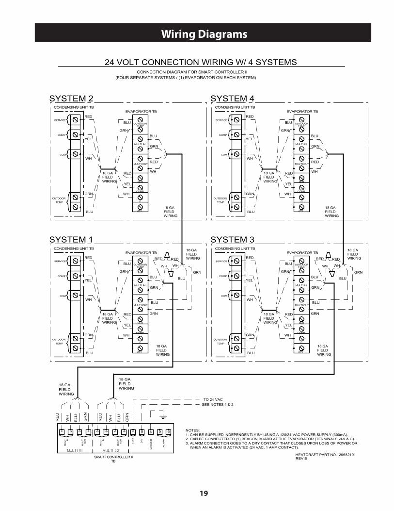
HEATCRAFT PART NO. 29664201REV C
NOTES:1. CAN BE SUPPLIED INDEPENDENTLY BY USING A 120/24 VAC POWER SUPPLY (300mA).2. CAN BE CONNECTED TO (1) BEACON BOARD AT THE EVAPORATOR (TERMINALS 24V & C).3. ALARM CONNECTION GOES TO A DRY CONTACT THAT CLOSES UPON LOSS OF POWER OR
WHEN AN ALARM IS ACTIVATED (24 VAC, 1 AMP CONTACT).
3 4 5 6 7 8 9 10
MU
LTI
IN
MU
LTI
OU
T
CO
M
24V
1 2
MU
LTI
IN
MU
LTI
OU
T
MULTI #1 MULTI #2
RE
D
WH
GR
N
BLU
SMART CONTROLLER IITB
18 GAFIELDWIRING
CONNECTION DIAGRAM FOR SMART CONTROLLER II
24 VOLT CONNECTION WIRING W/ 4 SYSTEMS
(FOUR SEPARATE SYSTEMS / (2) EVAPORATOR ON EACH SYSTEM)
18 GAFIELDWIRING
RE
D
WH
GR
N
BLU
SYSTEM 2
COMP
SERVICE
COM
OUTDOOR
TEMP
CONDENSING UNIT TB MASTEREVAPORATOR TB
BLU
GRN
YEL
WH
18 GAFIELDWIRING
RED
BLU
GRN
WH
YEL
RED
BLU
GRN
18 GAFIELDWIRING
BLU
MULTI OUT
MULTI IN
24V
COMP
SLAVEEVAPORATOR TB
WH
REDGRN
BLU
GRN
18 GAFIELDWIRING
MULTI OUT
MULTI IN
24V
COMP
SYSTEM 1
COMP
SERVICE
COM
OUTDOOR
TEMP
CONDENSING UNIT TB MASTEREVAPORATOR TB
BLU
GRN
YEL
WH
18 GAFIELDWIRING
RED
BLU
GRN
WH
YEL
RED
BLU
GRN18 GAFIELDWIRING
BLU
MULTI OUT
MULTI IN
24V
COMP
SLAVEEVAPORATOR TB
GRN
BLU
GRN
RED
WH
RED
WH
18 GAFIELDWIRING
MULTI OUT
MULTI IN
24V
COMP
BLU
GRN
SYSTEM 4
SYSTEM 3
COMP
SERVICE
COM
OUTDOOR
TEMP
CONDENSING UNIT TB MASTEREVAPORATOR TB
BLU
GRN
YEL
WH
18 GAFIELDWIRING
RED
BLU
GRN
WH
YEL
RED
BLU
GRN
18 GAFIELDWIRING
BLU
MULTI OUT
MULTI IN
24V
COMP
SLAVEEVAPORATOR TB
WH
REDGRN
BLU
GRN
18 GAFIELDWIRING
MULTI OUT
MULTI IN
24V
COMP
COMP
SERVICE
COM
OUTDOOR
TEMP
CONDENSING UNIT TB MASTEREVAPORATOR TB
BLU
GRN
YEL
WH
18 GAFIELDWIRING
RED
BLU
GRN
WH
YEL
RED
BLU
GRN18 GAFIELDWIRING
BLU
MULTI OUT
MULTI IN
24V
COMP
SLAVEEVAPORATOR TB
GRN
BLU
GRN
RED
WH
RED
WH
18 GAFIELDWIRING
MULTI OUT
MULTI IN
24V
COMP
BLU
GRN
TO 24 VACSEE NOTES 1 & 2
ALA
RM
11 12 13
GR
OU
ND
C
SER
OUTDOORTEMP
OUTDOORTEMP
C
SER
C
SER
OUTDOORTEMP
OUTDOORTEMP
C
SER
C
SER
OUTDOORTEMP
OUTDOORTEMP
C
SER
C
SER
OUTDOORTEMP
OUTDOORTEMP
C
SER
19
Wiring Diagrams
HEATCRAFT PART NO. 29682101
NOTES:1. CAN BE SUPPLIED INDEPENDENTLY BY USING A 120/24 VAC POWER SUPPLY (300mA).2. CAN BE CONNECTED TO (1) BEACON BOARD AT THE EVAPORATOR (TERMINALS 24V & C).3. ALARM CONNECTION GOES TO A DRY CONTACT THAT CLOSES UPON LOSS OF POWER OR
WHEN AN ALARM IS ACTIVATED (24 VAC, 1 AMP CONTACT).
3 4 5 6 7 8 9 10
MU
LTI
IN
MU
LTI
OU
T
CO
M
24V
1 2
MU
LTI
IN
MU
LTI
OU
T
MULTI #1 MULTI #2
RE
D
WH
GR
N
BLU
SMART CONTROLLER IITB
18 GAFIELDWIRING
CONNECTION DIAGRAM FOR SMART CONTROLLER II
24 VOLT CONNECTION WIRING W/ 4 SYSTEMS
(FOUR SEPARATE SYSTEMS / (1) EVAPORATOR ON EACH SYSTEM)
18 GAFIELDWIRING
RE
D
WH
GR
N
BLU
SYSTEM 2
COMP
SERVICE
COM
OUTDOOR
TEMP
CONDENSING UNIT TBEVAPORATOR TB
BLU
GRN
YEL
WH
18 GAFIELDWIRING
RED
BLU
GRN
WH
YEL
RED
18 GAFIELDWIRING
WH
RED
BLU
GRN
MULTI OUT
MULTI IN
24V
C
COMP
SER
SYSTEM 1
COMP
SERVICE
COM
OUTDOOR
TEMP
CONDENSING UNIT TB
BLU
GRN
YEL
WH
18 GAFIELDWIRING
RED
BLU
GRN
WH
YEL
RED
BLU
GRN
18 GAFIELDWIRING
BLU
GRN
RED
WH
RED
WH
18 GAFIELDWIRING
MULTI OUT
MULTI IN
24V
COMP
EVAPORATOR TB
BLU
GRN
SYSTEM 4
COMP
SERVICE
COM
OUTDOOR
TEMP
CONDENSING UNIT TBEVAPORATOR TB
BLU
GRN
YEL
WH
18 GAFIELDWIRING
RED
BLU
GRN
WH
YEL
RED
18 GAFIELDWIRING
WH
RED
BLU
GRN
MULTI OUT
MULTI IN
24V
COMP
SYSTEM 3
COMP
SERVICE
COM
OUTDOOR
TEMP
CONDENSING UNIT TB
BLU
GRN
YEL
WH
18 GAFIELDWIRING
RED
BLU
GRN
WH
YEL
RED
BLU
GRN
18 GAFIELDWIRING
BLU
GRN
RED
WH
RED
WH
18 GAFIELDWIRING
MULTI OUT
MULTI IN
24V
COMP
EVAPORATOR TB
BLU
GRN
ALA
RM
11 12 13
GR
OU
ND
REV B
TO 24 VACSEE NOTES 1 & 2
OUTDOORTEMP
OUTDOORTEMP
OUTDOORTEMP
OUTDOORTEMP
C
SER
C
SER
C
SER
20
Heatcraft Refrigeration Products, LLC2175 West Park Place Blvd • Stone Mountain, GA 30087(800) 321-1881 www.heatcraftrpd.com
Since product improvement is a continuing effort, we reserve the right to makechanges in specifications without notice.