Embed Size (px)
Citation preview
BEARING CAPACITY IMPROVEMENT using
geosynthetics
Lecture 28
Prof. G L Sivakumar BabuDepartment of Civil EngineeringIndian Institute of ScienceBangalore 560012Email: [email protected]
• Introduction• Modes of failure• Forces in reinforcement • Tension failure and pull out • Design steps• Examples
Introduction
Reinforced soil technique has been used very effectively isin the improvement of bearing capacity of foundation soils.Studies by several investigators (e.g. Binquet and Lee,1975a, 1975b; Guido et. al. 1986) clearly indicated theadvantages and possibilities of improvement in bearingcapacity and stiffness in terms of the load-settlementbehaviour by reinforcing foundation soil in the case ofsands.
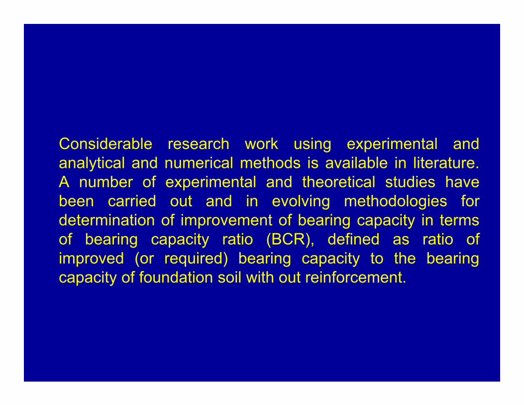
Considerable research work using experimental andanalytical and numerical methods is available in literature.A number of experimental and theoretical studies havebeen carried out and in evolving methodologies fordetermination of improvement of bearing capacity in termsof bearing capacity ratio (BCR), defined as ratio ofimproved (or required) bearing capacity to the bearingcapacity of foundation soil with out reinforcement.
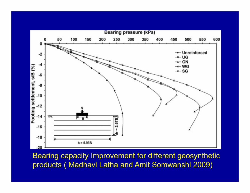
Bearing capacity Improvement for different geosynthetic products ( Madhavi Latha and Amit Somwanshi 2009)
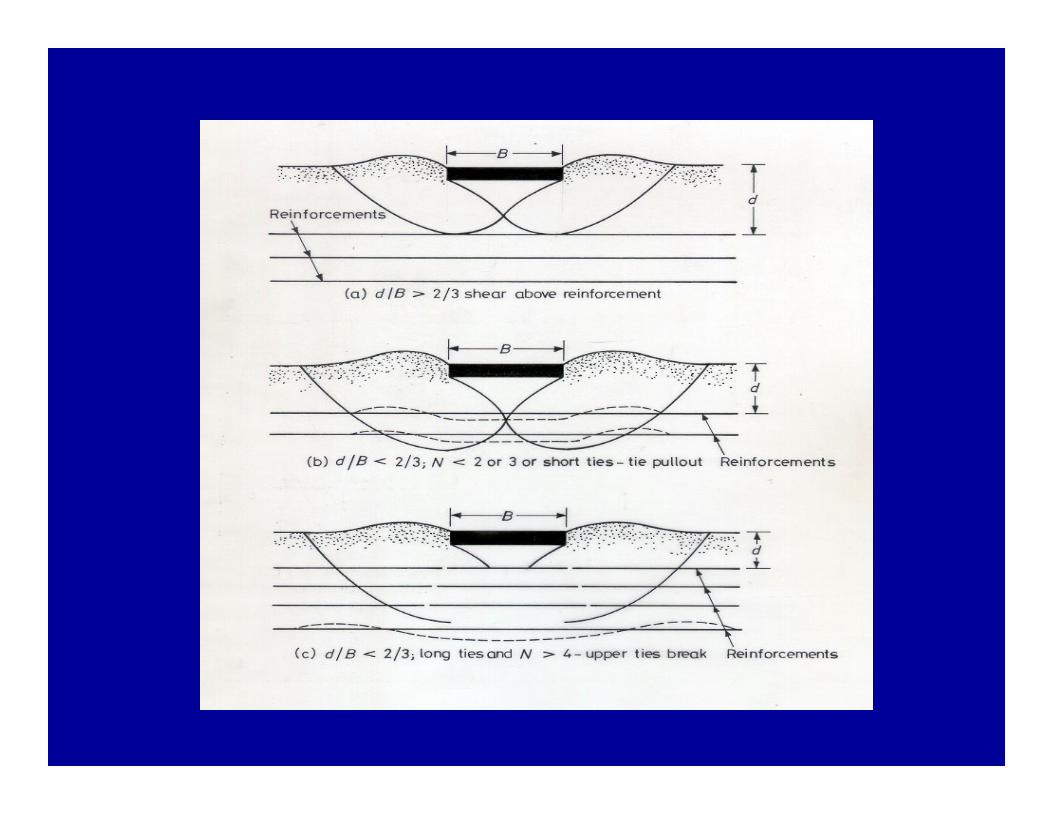
Binquet and Lee (1975) proposed a method to evaluatethe improvement in bearing capacity. When some formof reinforcement is used in the foundation soil, it isnecessary to identify the modes of failure due to thepresence of reinforcement so that the effectiveness ofthe reinforced foundation is examined. To develop adesign procedure, Binquet and Lee idealized that thefollowing mechanisms of failure are likely to occur in areinforced soil foundation.
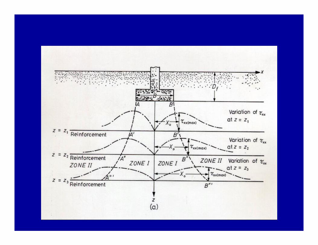
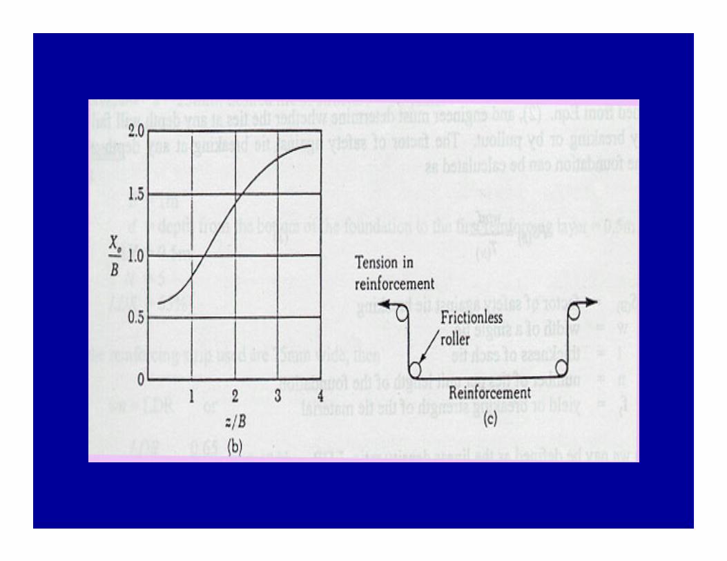
The points A’, A”, A’”, …. , and B’, B”, B’”,….., which define the limiting lines between zones I and II, can be obtained by considering the shear stress distribution, xz’ in the soil caused by the foundation load. The term xz refers to the shear stress developed at a depth z below the foundation at a distance x measured from the centerline of the foundation.For N reinforcing layers, the ratio of the load per unit area on the foundation supported by reinforced earth, qR, to the load per unit on the foundation supported by unreinforced earth, q0, is constant irrespective of the settlement level, s
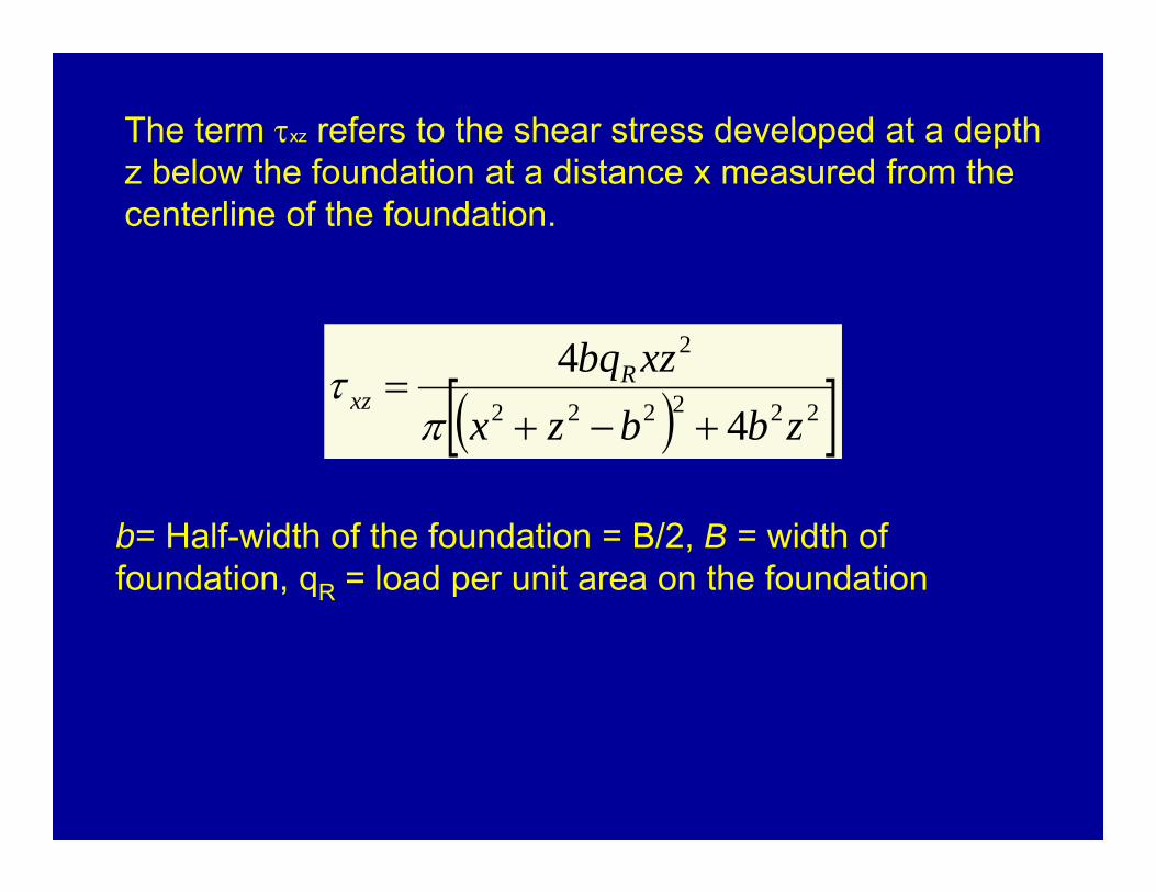
The term xz refers to the shear stress developed at a depth z below the foundation at a distance x measured from the centerline of the foundation.
222222
2
44
zbbzxxzbqR
xz
b= Half-width of the foundation = B/2, B = width of foundation, qR = load per unit area on the foundation
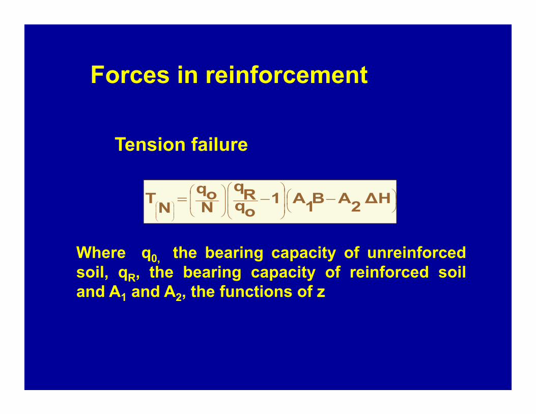
Forces in reinforcement
∆H2AB1A1oqRq
Noq
NT
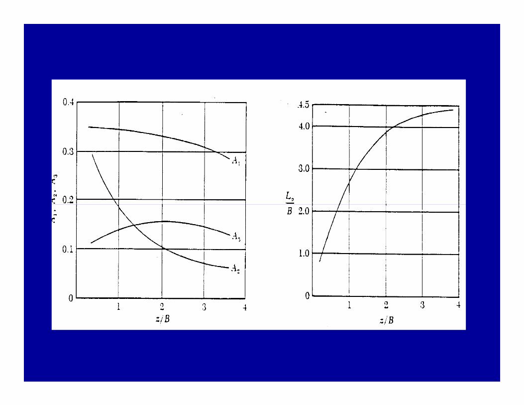
Tension failure
Where q0, the bearing capacity of unreinforcedsoil, qR, the bearing capacity of reinforced soiland A1 and A2, the functions of z
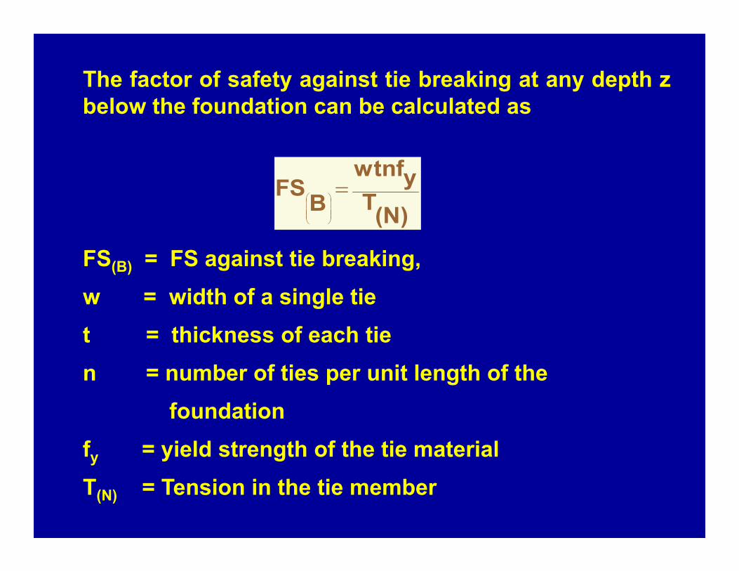
The factor of safety against tie breaking at any depth zbelow the foundation can be calculated as
FS(B) = FS against tie breaking,w = width of a single tiet = thickness of each tien = number of ties per unit length of the
foundationfy = yield strength of the tie materialT(N) = Tension in the tie member
(N)Tywtnf
BFS
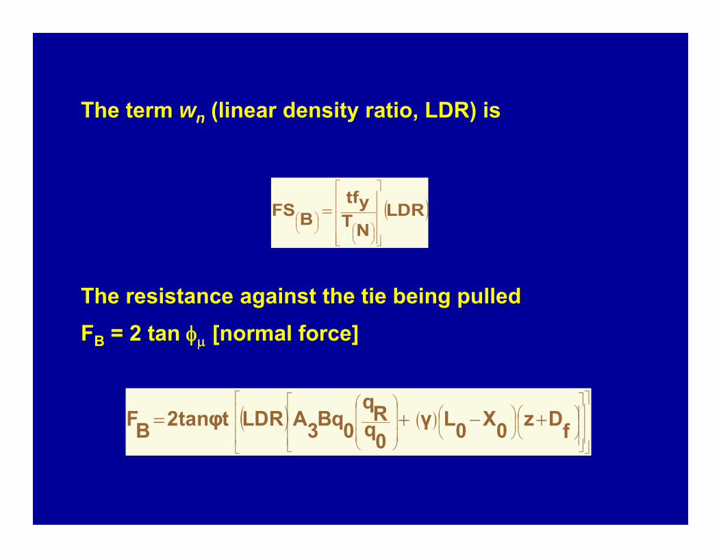
The term wn (linear density ratio, LDR) is
The resistance against the tie being pulledFB = 2 tan [normal force]
LDRNTytf
BFS
fDz0X0Lγ
0qRq
0Bq3ALDR2tanφtBF
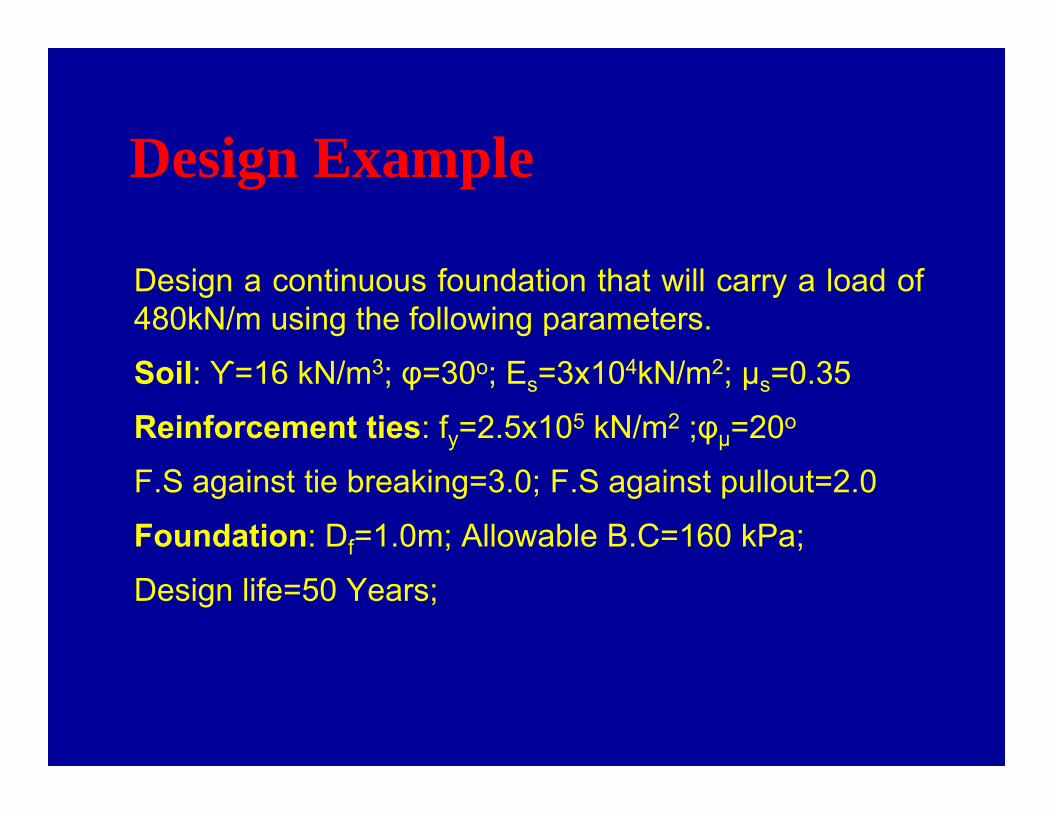
Design Example
Design a continuous foundation that will carry a load of480kN/m using the following parameters.
Soil: ϒ=16 kN/m3; φ=30o; Es=3x10⁴kN/m2; µs=0.35
Reinforcement ties: fy=2.5x10⁵ kN/m2 ;φµ=20o
F.S against tie breaking=3.0; F.S against pullout=2.0
Foundation: Df=1.0m; Allowable B.C=160 kPa;
Design life=50 Years;
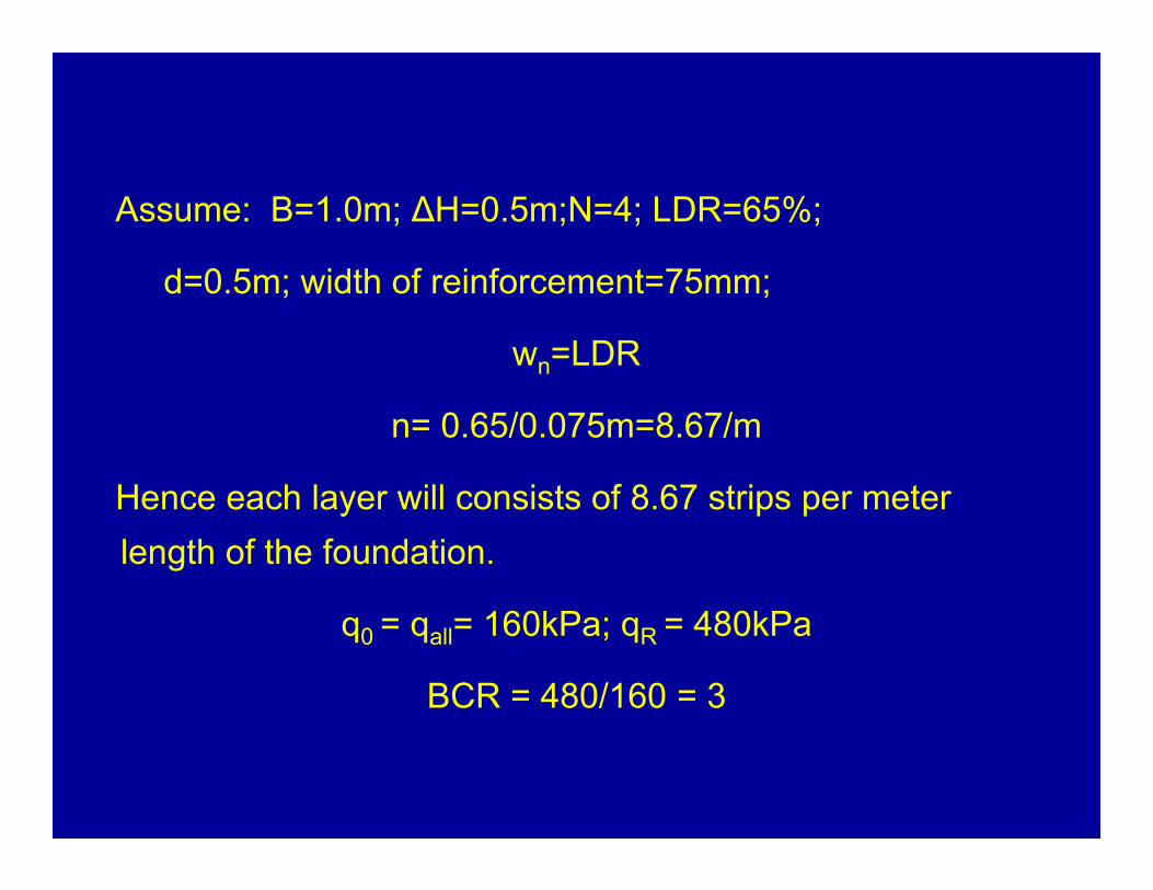
Assume: B=1.0m; ∆H=0.5m;N=4; LDR=65%;
d=0.5m; width of reinforcement=75mm;
wn=LDR
n= 0.65/0.075m=8.67/m
Hence each layer will consists of 8.67 strips per meter length of the foundation.
q0 = qall= 160kPa; qR = 480kPa
BCR = 480/160 = 3
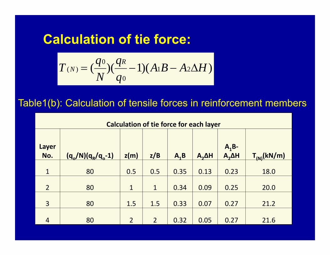
Calculation of tie force:
))(1)(( 210
0)( HABA
NqT R
N
Calculation of tie force for each layer
Layer No. (qo/N)(qR/qo‐1) z(m) z/B A1B A2∆H
A1B‐A2∆H T(N)(kN/m)
1 80 0.5 0.5 0.35 0.13 0.23 18.0
2 80 1 1 0.34 0.09 0.25 20.0
3 80 1.5 1.5 0.33 0.07 0.27 21.2
4 80 2 2 0.32 0.05 0.27 21.6
Table1(b): Calculation of tensile forces in reinforcement members
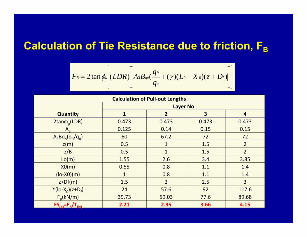
Calculation of Tie Resistance due to friction, FB
))()((()(tan2 003 f
o
RqoB DzXL
qqBALDRF
Calculation of Pull‐out Lengths
QuantityLayer No
1 2 3 42tanɸµ(LDR) 0.473 0.473 0.473 0.473
A3 0.125 0.14 0.15 0.15A3Bqo(qR/q0) 60 67.2 72 72
z(m) 0.5 1 1.5 2z/B 0.5 1 1.5 2
Lo(m) 1.55 2.6 3.4 3.85X0(m) 0.55 0.8 1.1 1.4
(lo‐X0)(m) 1 0.8 1.1 1.4z+Df(m) 1.5 2 2.5 3
ϒ(lo‐X0)(z+Df) 24 57.6 92 117.6FB(kN/m) 39.73 59.03 77.6 89.68
FS(p)=FB/T(N) 2.21 2.95 3.66 4.15
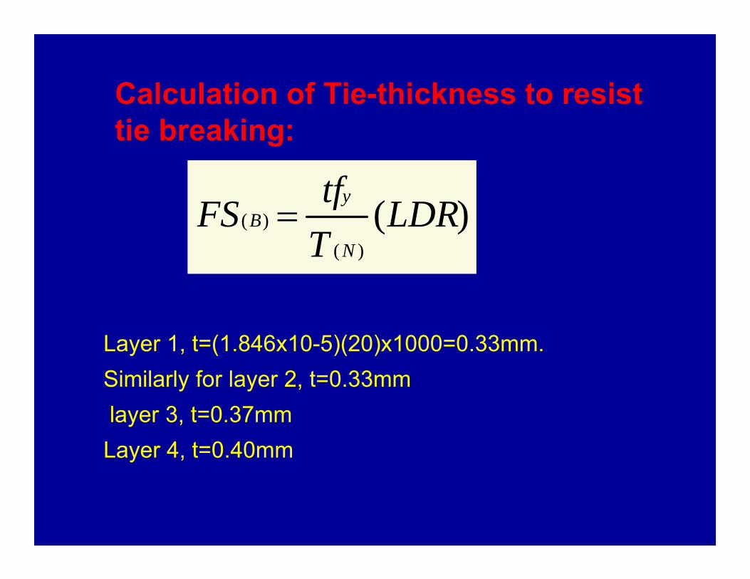
Calculation of Tie-thickness to resist tie breaking:
Layer 1, t=(1.846x10⁻⁵)(20)x1000=0.33mm.Similarly for layer 2, t=0.33mmlayer 3, t=0.37mmLayer 4, t=0.40mm
)()(
)( LDRTtfFS
N
yB
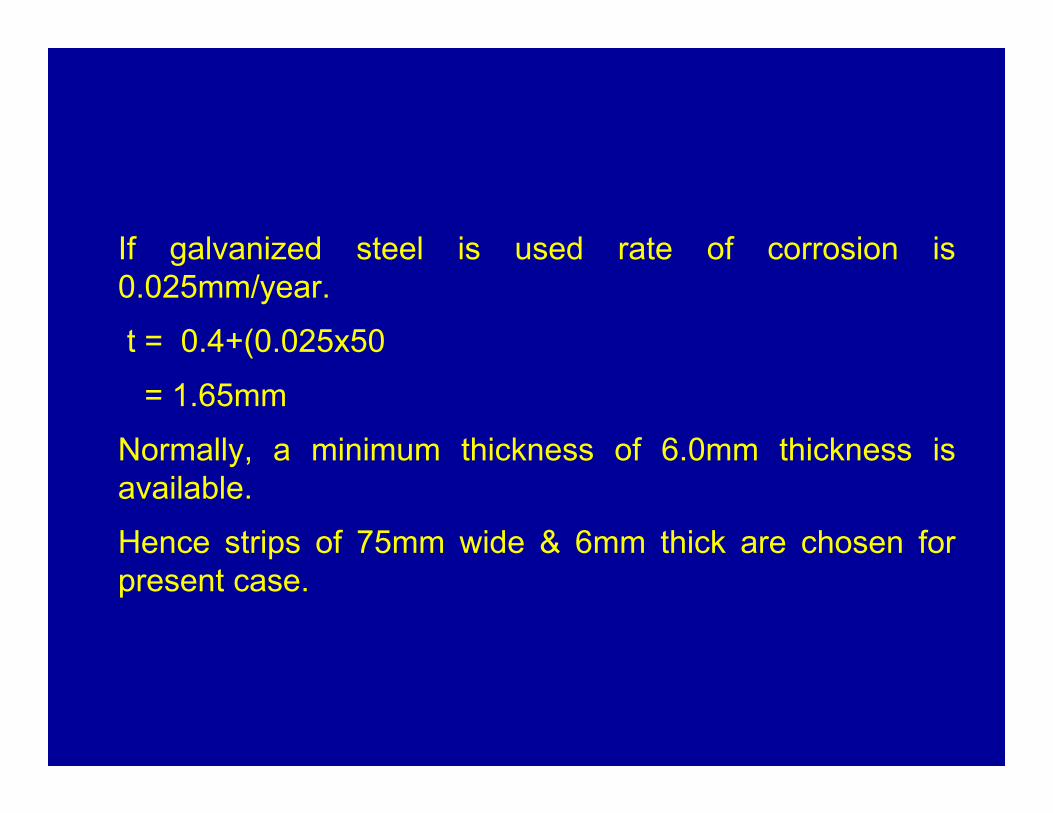
If galvanized steel is used rate of corrosion is0.025mm/year.
t = 0.4+(0.025x50
= 1.65mm
Normally, a minimum thickness of 6.0mm thickness isavailable.
Hence strips of 75mm wide & 6mm thick are chosen forpresent case.
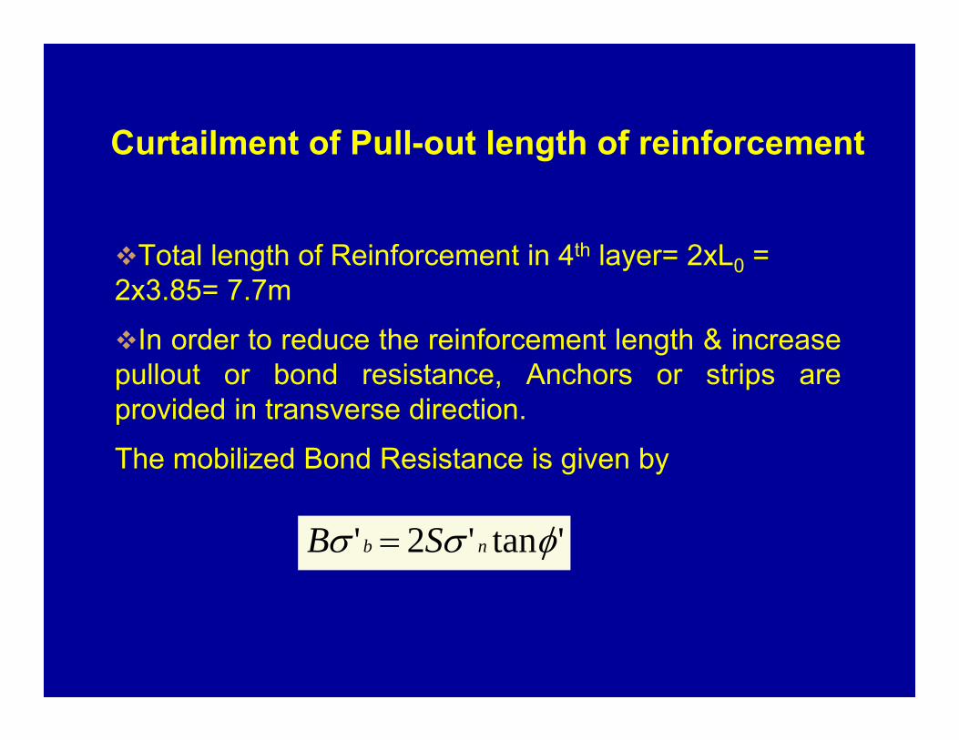
Curtailment of Pull-out length of reinforcement
Total length of Reinforcement in 4th layer= 2xL0 = 2x3.85= 7.7m
In order to reduce the reinforcement length & increasepullout or bond resistance, Anchors or strips areprovided in transverse direction.
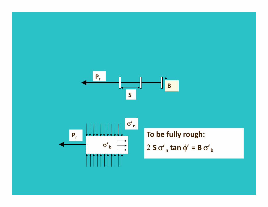
The mobilized Bond Resistance is given by
'tan'2' nb SB
SB
Pr
Pr
n
b
To be fully rough:
S n tan = B b
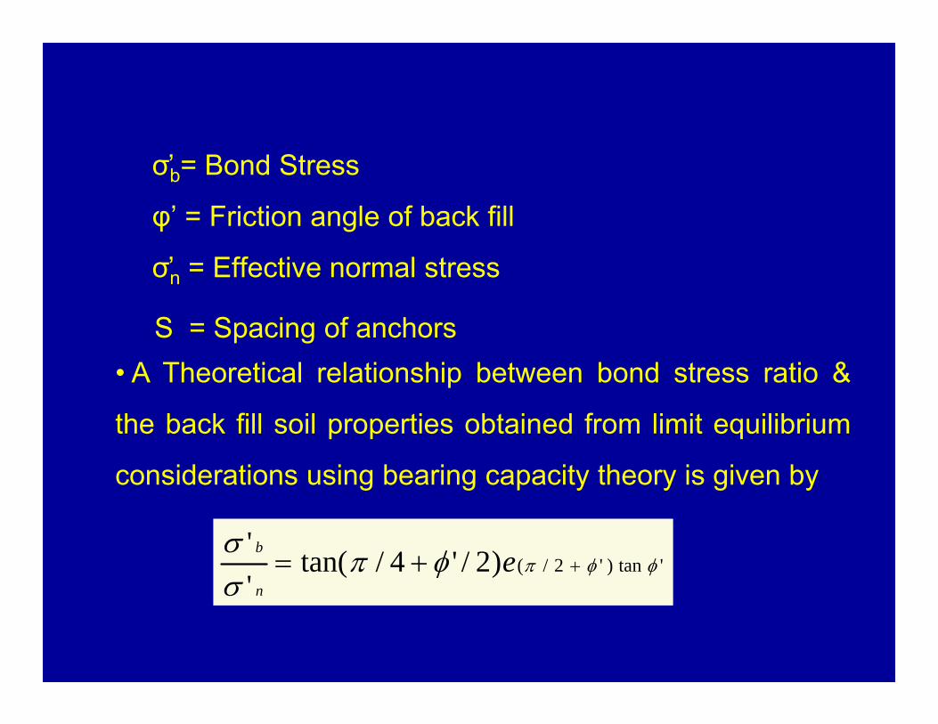
σ̕b= Bond Stress
φ’ = Friction angle of back fill
σ̕n = Effective normal stress
S = Spacing of anchors• A Theoretical relationship between bond stress ratio &
the back fill soil properties obtained from limit equilibrium
considerations using bearing capacity theory is given by
'tan)'2/()2/'4/tan(''
en
b
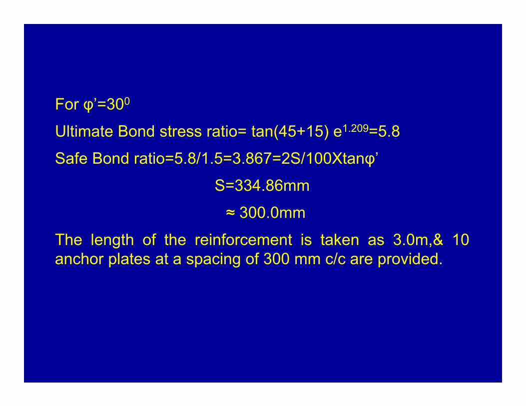
For φ’=300
Ultimate Bond stress ratio= tan(45+15) e1.209=5.8
Safe Bond ratio=5.8/1.5=3.867=2S/100Xtanφ’
S=334.86mm
≈ 300.0mm
The length of the reinforcement is taken as 3.0m,& 10anchor plates at a spacing of 300 mm c/c are provided.

Calculation of Bond resistance of Anchor plates
Calculation of Bond Resistance of Anchor Plates
(z+Df)(m) Effective normal Stress(kPa)
Bond resistance per Anchor(kPa)
Tensile force per meter length(kN/m)
Factor of safety against pullout
1.5 24 92.8 18 5.16
2 32 123.7 20 6.19
2.5 40 154.7 22 7.03
3 48 185.6 22.4 8.29
Calculation of bond resistance of anchor plates
Factor of safety against pull out is is >2.0; Hence O.K.
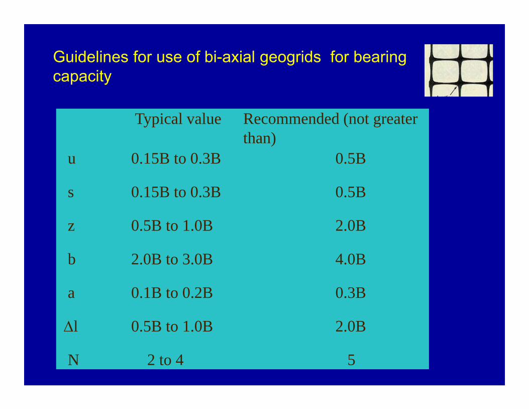
Typical value Recommended (not greater than)
u 0.15B to 0.3B 0.5B
s 0.15B to 0.3B 0.5B
z 0.5B to 1.0B 2.0B
b 2.0B to 3.0B 4.0B
a 0.1B to 0.2B 0.3B
l 0.5B to 1.0B 2.0B
N 2 to 4 5
Guidelines for use of bi-axial geogrids for bearing capacity
Improvement of bearing capacity of soft soils
Use of sand and aggregates, Use of geotextiles, geogrids and geocells
The improvement is attributed to three effects a) shear layer effect b) confinement effect due to the interaction between sand and reinforcement in the sand layer and c) additional surcharge effects.
The ultimate bearing capacity of a footing resting on soft soil qu = CuNc
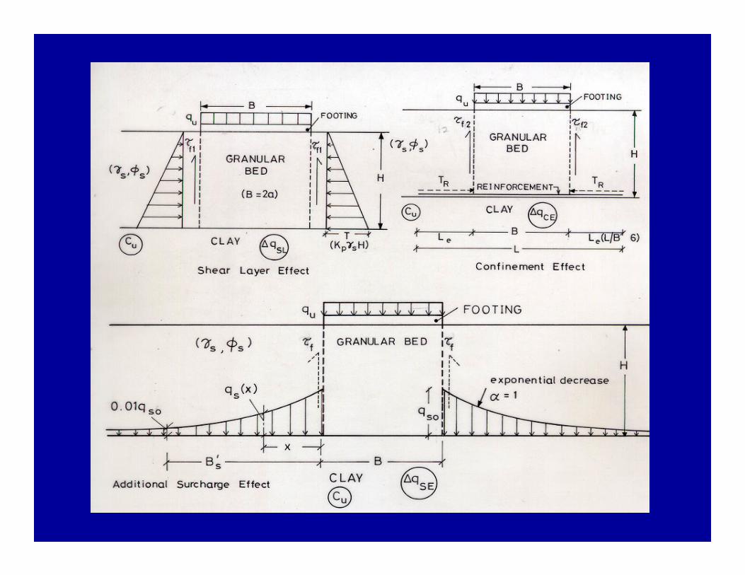
When a granular bed of thickness (H) of bulk density (s) and friction angle (s) with reinforcement is provided over soft soil, the bearing capacity of the footing resting on this foundation medium is increased. Frictional forces developed between the soil and the reinforcement induce tensile strains in the reinforcement. The tensile strains developed provide the confining effect. This will induce additional shearing resistance along the vertical plane at the edge and exponentially decrease with distance away from the edge of the footing. The three effects contribute to increase in bearing capacity, given as
qu + qR = Cu Nc + qSL + qCE + qSE

Tf1 =
tans (4.14)
An example illustrating the application of the aboveformulation is given below.Design a continuous foundation (B = 1m) that will carry aload of 480 kN/m that needs to be constructed on a softsoil and the undrained strength (Cu) of the soil is 10 kPa.
SolutionThe ultimate bearing capacity of the soft soil
(qu)= CuNc = 10 x 5.14 = 51.4 kPa
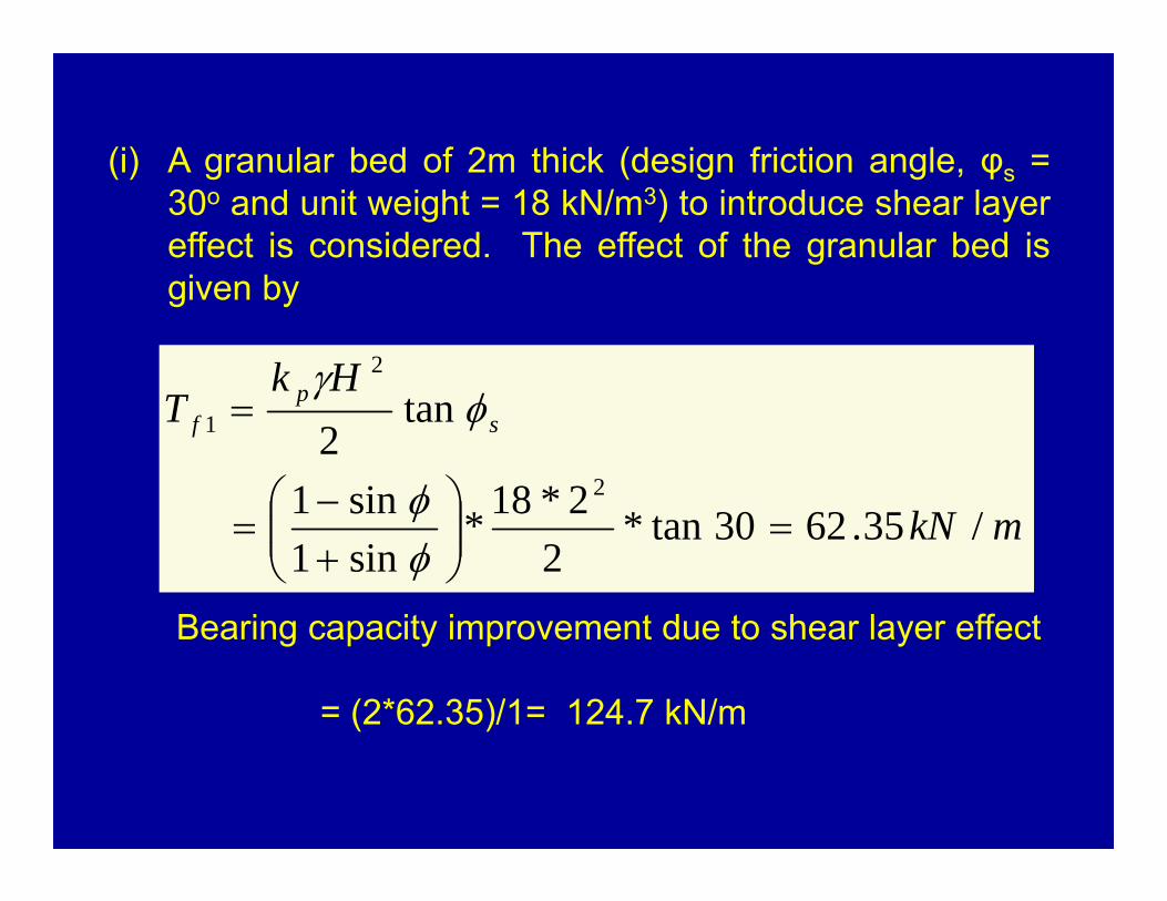
(i) A granular bed of 2m thick (design friction angle, φs =30o and unit weight = 18 kN/m3) to introduce shear layereffect is considered. The effect of the granular bed isgiven by
Bearing capacity improvement due to shear layer effect
= (2*62.35)/1= 124.7 kN/m
mkN
HkT s
pf
/35.6230tan*2
2*18*sin1sin1
tan2
2
2
1
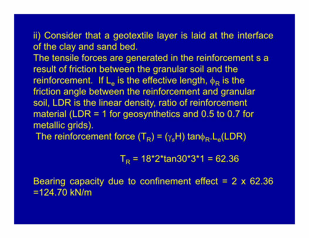
ii) Consider that a geotextile layer is laid at the interfaceof the clay and sand bed.The tensile forces are generated in the reinforcement s a result of friction between the granular soil and the reinforcement. If Le is the effective length, R is the friction angle between the reinforcement and granular soil, LDR is the linear density, ratio of reinforcement material (LDR = 1 for geosynthetics and 0.5 to 0.7 for metallic grids).The reinforcement force (TR) = (sH) tanR.Le(LDR)
TR = 18*2*tan30*3*1 = 62.36
Bearing capacity due to confinement effect = 2 x 62.36=124.70 kN/m
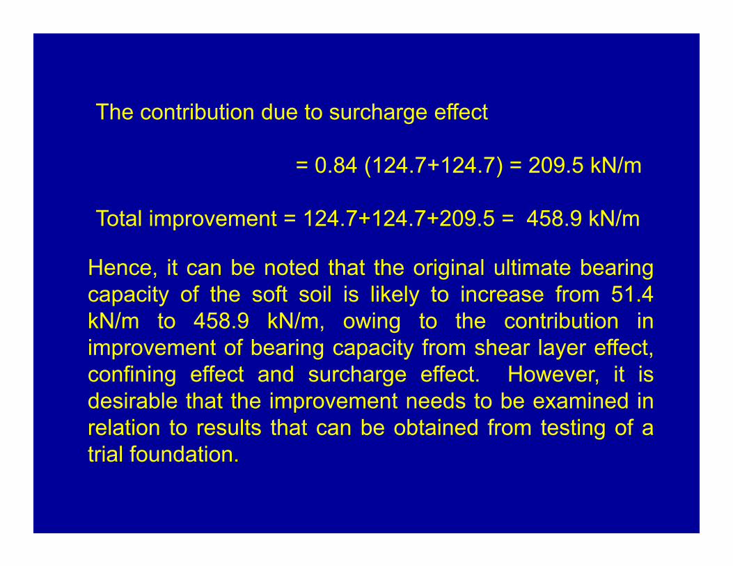
Hence, it can be noted that the original ultimate bearingcapacity of the soft soil is likely to increase from 51.4kN/m to 458.9 kN/m, owing to the contribution inimprovement of bearing capacity from shear layer effect,confining effect and surcharge effect. However, it isdesirable that the improvement needs to be examined inrelation to results that can be obtained from testing of atrial foundation.
The contribution due to surcharge effect
= 0.84 (124.7+124.7) = 209.5 kN/m
Total improvement = 124.7+124.7+209.5 = 458.9 kN/m