Embed Size (px)
Citation preview
Bearing investigation
Extract from the Railway technical handbook, volume 1, chapter 6, page 122 to 135
Bearing 6 investigation
Considerations . . . . . . . . . . . . . . 123
Trouble in operation . . . . . . . . . . 125
Bearing damage . . . . . . . . . . . . . 126
Damage and failure matrix . . . . . 135
122
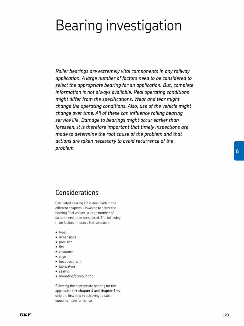
Bearing investigation
Roller bearings are extremely vital components in any railway application. A large number of factors need to be considered to select the appropriate bearing for an application. But, complete information is not always available. Real operating conditions might differ from the specifications. Wear and tear might change the operating conditions. Also, use of the vehicle might change over time. All of these can influence rolling bearing service life. Damage to bearings might occur earlier than foreseen. It is therefore important that timely inspections are made to determine the root cause of the problem and that actions are taken necessary to avoid recurrence of the problem.
ConsiderationsCalculated bearing life is dealt with in the different chapters . However, to select the bearing final variant, a large number of factors need to be considered . The following main factors influence this selection:
type• dimensions• precision• fits• clearance• cage• heat treatment• lubrication• sealing• mounting/dismounting•
Selecting the appropriate bearing for the application († chapter 4 and chapter 5) is only the first step in achieving reliable equipment performance .
123
6
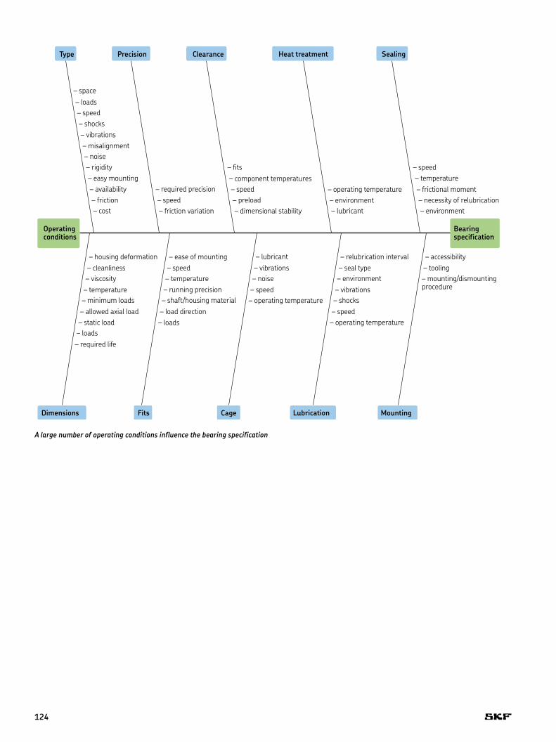
A large number of operating conditions influence the bearing specification
Type
Operatingconditions
– mounting/dismounting procedure
MountingLubricationCageFitsDimensions
– tooling– accessibility
– operating temperature– speed– shocks– vibrations– environment– seal type– relubrication interval
– operating temperature– speed– noise– vibrations– lubricant
– loads– load direction– shaft/housing material– running precision– temperature– speed– ease of mounting
– required life– loads– static load– allowed axial load– minimum loads– temperature– viscosity– cleanliness– housing deformation
Bearingspecification
– environment– necessity of relubrication– frictional moment– temperature– speed
– lubricant– environment– operating temperature
– dimensional stability– preload– speed– component temperatures– fits
– friction variation– speed– required precision
– cost– friction– availability– easy mounting– rigidity– noise– misalignment– vibrations– shocks– speed– loads– space
SealingHeat treatmentClearancePrecision
124
Trouble in operationIf all the assumptions in the table are met, a bearing would reach its calculated life .
Unfortunately, this is quite hypothetical . There is often something that occurs that prevents “ideal” operating conditions . Bearings might get damaged and their life impaired .
Even the smallest event can have severe consequences – an example:
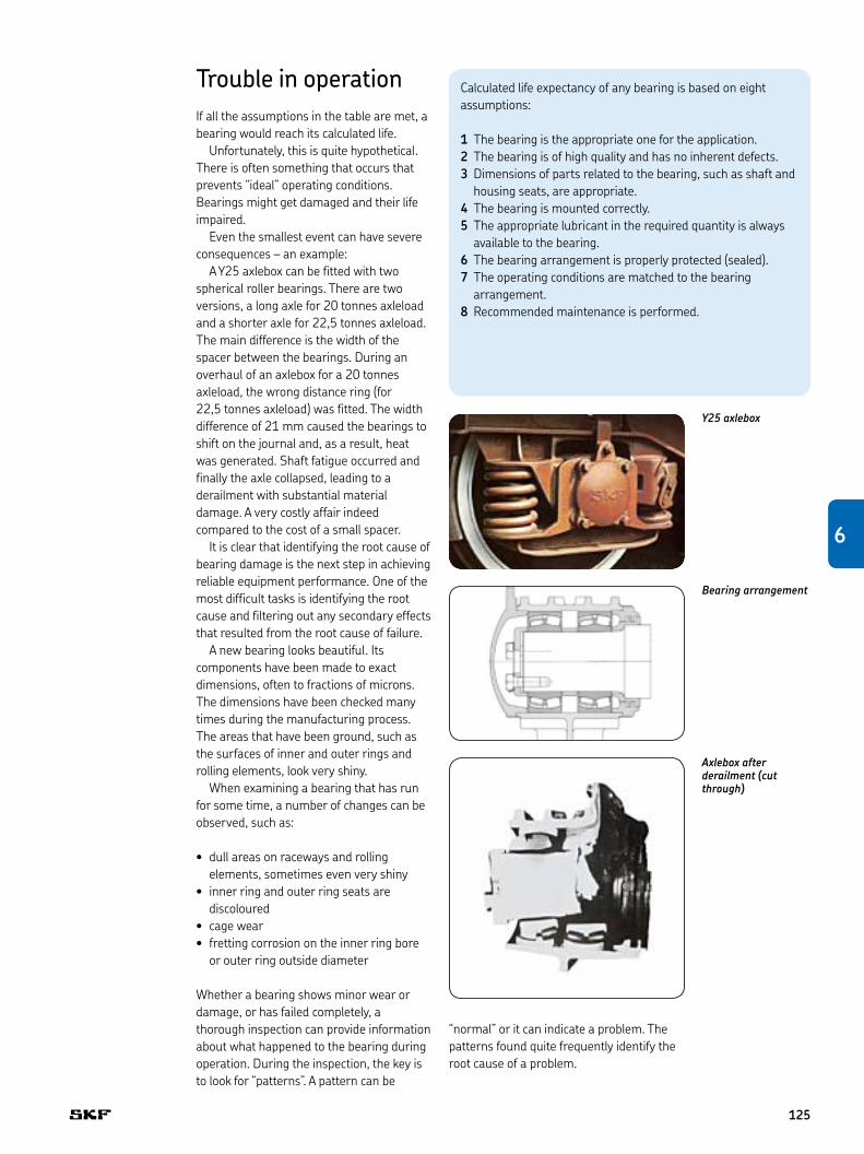
A Y25 axlebox can be fitted with two spherical roller bearings . There are two versions, a long axle for 20 tonnes axleload and a shorter axle for 22,5 tonnes axleload . The main difference is the width of the spacer between the bearings . During an overhaul of an axlebox for a 20 tonnes axleload, the wrong distance ring (for 22,5 tonnes axleload) was fitted . The width difference of 21 mm caused the bearings to shift on the journal and, as a result, heat was generated . Shaft fatigue occurred and finally the axle collapsed, leading to a derailment with substantial material damage . A very costly affair indeed compared to the cost of a small spacer .
It is clear that identifying the root cause of bearing damage is the next step in achieving reliable equipment performance . One of the most difficult tasks is identifying the root cause and filtering out any secondary effects that resulted from the root cause of failure .
A new bearing looks beautiful . Its components have been made to exact dimensions, often to fractions of microns . The dimensions have been checked many times during the manufacturing process . The areas that have been ground, such as the surfaces of inner and outer rings and rolling elements, look very shiny .
When examining a bearing that has run for some time, a number of changes can be observed, such as:
dull areas on raceways and rolling • elements, sometimes even very shinyinner ring and outer ring seats are • discolouredcage wear• fretting corrosion on the inner ring bore • or outer ring outside diameter
Whether a bearing shows minor wear or damage, or has failed completely, a thorough inspection can provide information about what happened to the bearing during operation . During the inspection, the key is to look for “patterns” . A pattern can be
Y25 axlebox
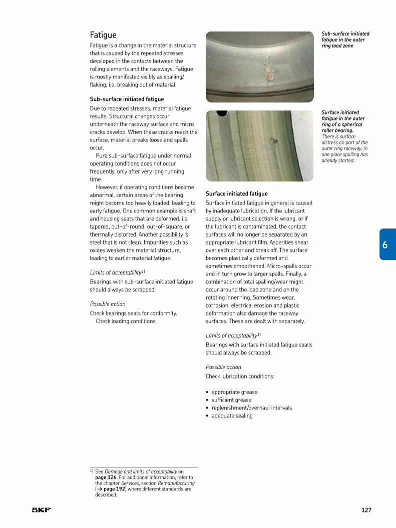
Axlebox after derailment (cut through)
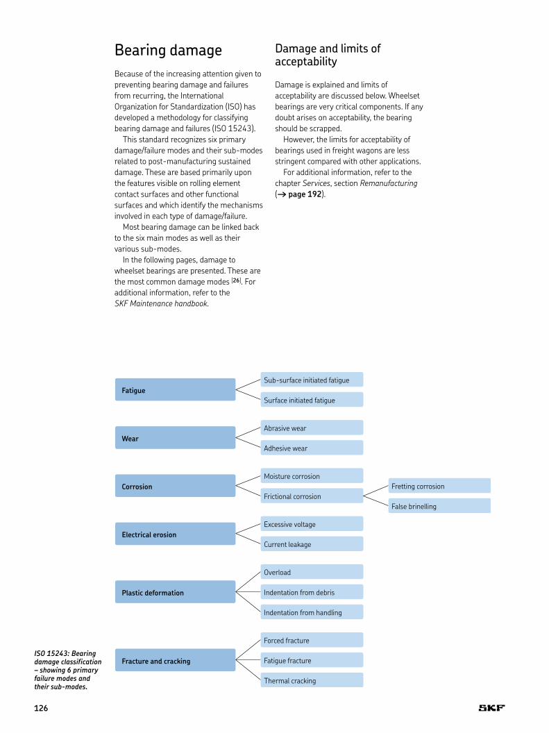
Bearing arrangement
“normal” or it can indicate a problem . The patterns found quite frequently identify the root cause of a problem .
Calculated life expectancy of any bearing is based on eight assumptions:
The bearing is the appropriate one for the application .1 The bearing is of high quality and has no inherent defects .2 Dimensions of parts related to the bearing, such as shaft and 3 housing seats, are appropriate .The bearing is mounted correctly .4 The appropriate lubricant in the required quantity is always 5 available to the bearing .The bearing arrangement is properly protected (sealed) .6 The operating conditions are matched to the bearing 7 arrangement .Recommended maintenance is performed .8
6
125
Bearing damageBecause of the increasing attention given to preventing bearing damage and failures from recurring, the International Organization for Standardization (ISO) has developed a methodology for classifying bearing damage and failures (ISO 15243) .
This standard recognizes six primary damage/failure modes and their sub-modes related to post-manufacturing sustained damage . These are based primarily upon the features visible on rolling element contact surfaces and other functional surfaces and which identify the mechanisms involved in each type of damage/failure .
Most bearing damage can be linked back to the six main modes as well as their various sub-modes .
In the following pages, damage to wheelset bearings are presented . These are the most common damage modes [26] . For additional information, refer to the SKF Maintenance handbook .
ISO 15243: Bearing damage classification – showing 6 primary failure modes and their sub-modes.
Damage and limits of acceptability
Damage is explained and limits of acceptability are discussed below . Wheelset bearings are very critical components . If any doubt arises on acceptability, the bearing should be scrapped .
However, the limits for acceptability of bearings used in freight wagons are less stringent compared with other applications .
For additional information, refer to the chapter Services, section Remanufacturing († page 192) .
Fracture and cracking
False brinelling
Fretting corrosion
Thermal cracking
Fatigue fracture
Forced fracture
Indentation from handling
Indentation from debris
Overload
Current leakage
Excessive voltage
Frictional corrosion
Moisture corrosion
Adhesive wear
Abrasive wear
Surface initiated fatigue
Sub-surface initiated fatigue
Plastic deformation
Electrical erosion
Corrosion
Wear
Fatigue
126
FatigueFatigue is a change in the material structure that is caused by the repeated stresses developed in the contacts between the rolling elements and the raceways . Fatigue is mostly manifested visibly as spalling/flaking, i .e . breaking out of material .
Sub-surface initiated fatigueDue to repeated stresses, material fatigue results . Structural changes occur underneath the raceway surface and micro cracks develop . When these cracks reach the surface, material breaks loose and spalls occur .
Pure sub-surface fatigue under normal operating conditions does not occur frequently, only after very long running time .
However, if operating conditions become abnormal, certain areas of the bearing might become too heavily loaded, leading to early fatigue . One common example is shaft and housing seats that are deformed, i .e . tapered, out-of-round, out-of-square, or thermally distorted . Another possibility is steel that is not clean . Impurities such as oxides weaken the material structure, leading to earlier material fatigue .
Limits of acceptability1)
Bearings with sub-surface initiated fatigue should always be scrapped .
Possible actionCheck bearings seats for conformity .
Check loading conditions .
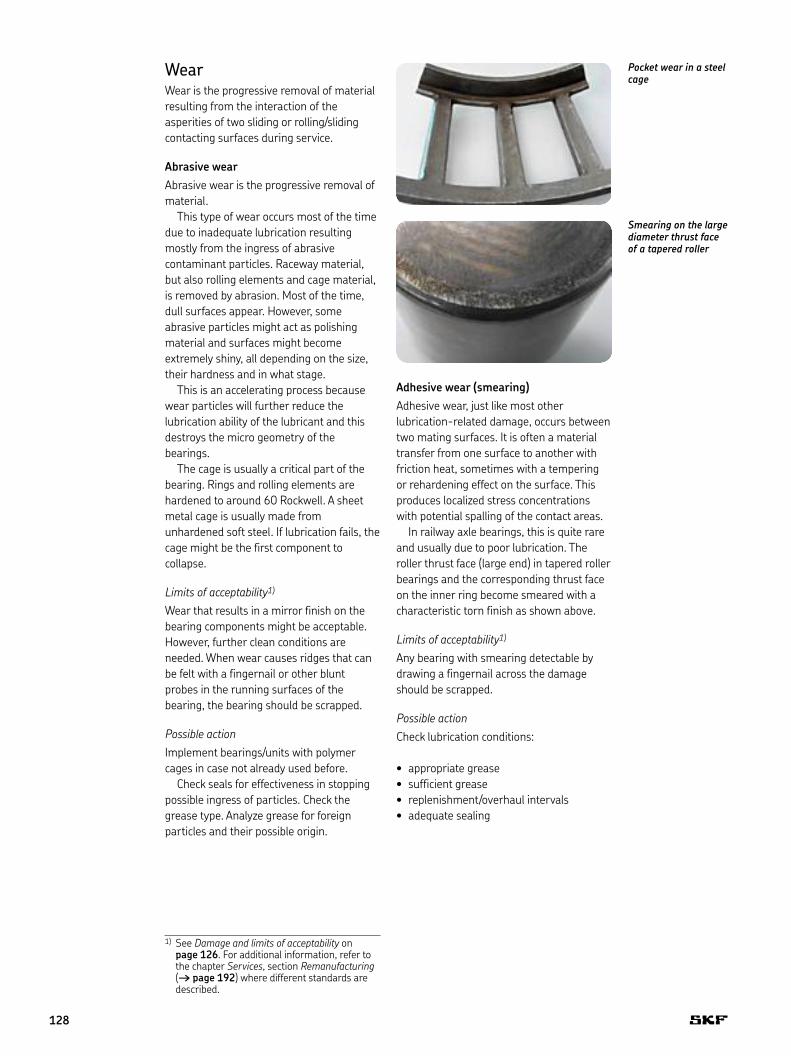
Sub-surface initiated fatigue in the outer ring load zone
Surface initiated fatigue in the outer ring of a spherical roller bearing.There is surface distress on part of the outer ring raceway. In one place spalling has already started.
Surface initiated fatigueSurface initiated fatigue in general is caused by inadequate lubrication . If the lubricant supply or lubricant selection is wrong, or if the lubricant is contaminated, the contact surfaces will no longer be separated by an appropriate lubricant film . Asperities shear over each other and break off . The surface becomes plastically deformed and sometimes smoothened . Micro-spalls occur and in turn grow to larger spalls . Finally, a combination of total spalling/wear might occur around the load zone and on the rotating inner ring . Sometimes wear, corrosion, electrical erosion and plastic deformation also damage the raceway surfaces . These are dealt with separately .
Limits of acceptability1)
Bearings with surface initiated fatigue spalls should always be scrapped .
Possible actionCheck lubrication conditions:
appropriate grease• sufficient grease• replenishment/overhaul intervals• adequate sealing•
1) See Damage and limits of acceptability on page 126 . For additional information, refer to the chapter Services, section Remanufacturing († page 192) where different standards are described .
6
127
WearWear is the progressive removal of material resulting from the interaction of the asperities of two sliding or rolling/sliding contacting surfaces during service .
Abrasive wearAbrasive wear is the progressive removal of material .
This type of wear occurs most of the time due to inadequate lubrication resulting mostly from the ingress of abrasive contaminant particles . Raceway material, but also rolling elements and cage material, is removed by abrasion . Most of the time, dull surfaces appear . However, some abrasive particles might act as polishing material and surfaces might become extremely shiny, all depending on the size, their hardness and in what stage .
This is an accelerating process because wear particles will further reduce the lubrication ability of the lubricant and this destroys the micro geometry of the bearings .
The cage is usually a critical part of the bearing . Rings and rolling elements are hardened to around 60 Rockwell . A sheet metal cage is usually made from unhardened soft steel . If lubrication fails, the cage might be the first component to collapse .
Limits of acceptability1)
Wear that results in a mirror finish on the bearing components might be acceptable . However, further clean conditions are needed . When wear causes ridges that can be felt with a fingernail or other blunt probes in the running surfaces of the bearing, the bearing should be scrapped .
Possible actionImplement bearings/units with polymer cages in case not already used before .
Check seals for effectiveness in stopping possible ingress of particles . Check the grease type . Analyze grease for foreign particles and their possible origin .
Pocket wear in a steel cage
Adhesive wear (smearing)Adhesive wear, just like most other lubrication-related damage, occurs between two mating surfaces . It is often a material transfer from one surface to another with friction heat, sometimes with a tempering or rehardening effect on the surface . This produces localized stress concentrations with potential spalling of the contact areas .
In railway axle bearings, this is quite rare and usually due to poor lubrication . The roller thrust face (large end) in tapered roller bearings and the corresponding thrust face on the inner ring become smeared with a characteristic torn finish as shown above .
Limits of acceptability1)
Any bearing with smearing detectable by drawing a fingernail across the damage should be scrapped .
Possible actionCheck lubrication conditions:
appropriate grease• sufficient grease• replenishment/overhaul intervals• adequate sealing•
Smearing on the large diameter thrust face of a tapered roller
1) See Damage and limits of acceptability on page 126 . For additional information, refer to the chapter Services, section Remanufacturing († page 192) where different standards are described .
128
Corrosion
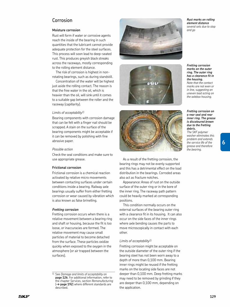
Moisture corrosionRust will form if water or corrosive agents reach the inside of the bearing in such quantities that the lubricant cannot provide adequate protection for the steel surfaces . This process will soon lead to deep-seated rust . This produces greyish black streaks across the raceways, mostly corresponding to the rolling element distance .
The risk of corrosion is highest in non-rotating bearings, such as during standstill .
Concentration of the water will be highest just aside the rolling contact . The reason is that the free water in the oil, which is heavier than the oil, will sink until it comes to a suitable gap between the roller and the raceway (capillarity) .
Limits of acceptability1)
Bearing components with corrosion damage that can be felt with a finger nail should be scrapped . A stain on the surface of the bearing components might be acceptable if it can be removed by polishing with fine abrasive paper .
Possible actionCheck the seal conditions and make sure to use appropriate grease .
Frictional corrosion Frictional corrosion is a chemical reaction activated by relative micro movements between contacting surfaces under certain conditions inside a bearing . Railway axle bearings usually suffer from either fretting corrosion or wear caused by vibration which is also known as false brinelling .
Fretting corrosionFretting corrosion occurs when there is a relative movement between a bearing ring and shaft or housing, because the fit is too loose, or inaccuracies are formed . The relative movement may cause small particles of material to become detached from the surface . These particles oxidize quickly when exposed to the oxygen in the atmosphere (or air trapped between the surfaces) .
Rust marks on rolling element distanceseveral sets due to stop and go
As a result of the fretting corrosion, the bearing rings may not be evenly supported and this has a detrimental effect on the load distribution in the bearings . Corroded areas also act as fracture notches .
Appearance: Areas of rust on the outside surface of the outer ring or in the bore of the inner ring . The raceway path pattern could be heavily marked at corresponding positions .
This condition normally occurs on the external surfaces of the bearing outer ring with a clearance fit in its housing . It can also occur on the side faces of the inner rings where axle bending causes the parts to move microscopically in contact with each other .
Limits of acceptability1)
Fretting corrosion might be acceptable on the outside diameter of the outer ring if the bearing steel has not been worn away to a depth of more than 0,100 mm . Bearing inner rings might be reused if the fretting marks on the locating side faces are not deeper than 0,100 mm . Deep fretting marks may need to be removed by grinding if they are deeper than 0,100 mm, depending on the application .
Fretting corrosion on a rear seal and rear inner ring. The grease is discoloured brown due to the fretting debris.The SKF polymer washer eliminates this problem and extends the service life of the grease and therefore the bearing.
Fretting corrosion marks on the outer ring. The outer ring has a clearance fit in the housing.Note that the contact marks are not even or in line, suggesting an uneven load acting on the axlebox housing.
1) See Damage and limits of acceptability on page 126 . For additional information, refer to the chapter Services, section Remanufacturing († page 192) where different standards are described .
6
129
Possible actionUse special anti-fretting paste on the surfaces .
Implement bearing units with a polyamide spacer between the backing ring and the inner ring side face in case not already used before († page 80) .
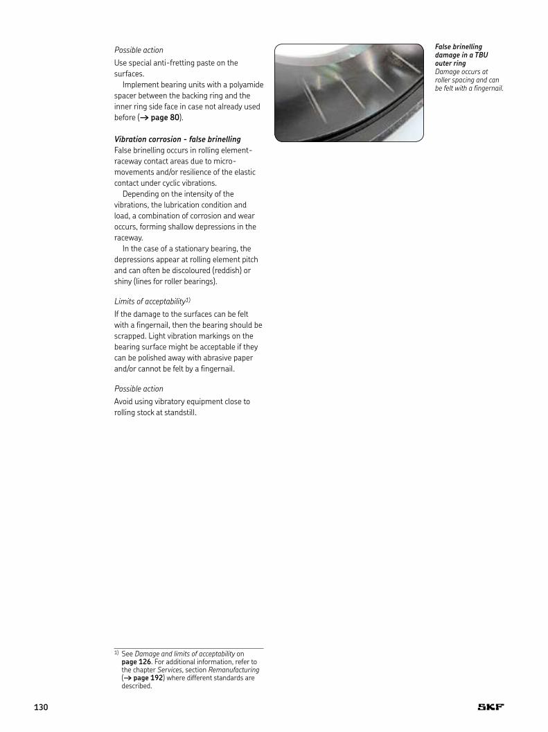
Vibration corrosion - false brinellingFalse brinelling occurs in rolling element-raceway contact areas due to micro-movements and/or resilience of the elastic contact under cyclic vibrations .
Depending on the intensity of the vibrations, the lubrication condition and load, a combination of corrosion and wear occurs, forming shallow depressions in the raceway .
In the case of a stationary bearing, the depressions appear at rolling element pitch and can often be discoloured (reddish) or shiny (lines for roller bearings) .
Limits of acceptability1)
If the damage to the surfaces can be felt with a fingernail, then the bearing should be scrapped . Light vibration markings on the bearing surface might be acceptable if they can be polished away with abrasive paper and/or cannot be felt by a fingernail .
Possible actionAvoid using vibratory equipment close to rolling stock at standstill .
False brinelling damage in a TBU outer ringDamage occurs at roller spacing and can be felt with a fingernail.
1) See Damage and limits of acceptability on page 126 . For additional information, refer to the chapter Services, section Remanufacturing († page 192) where different standards are described .
130
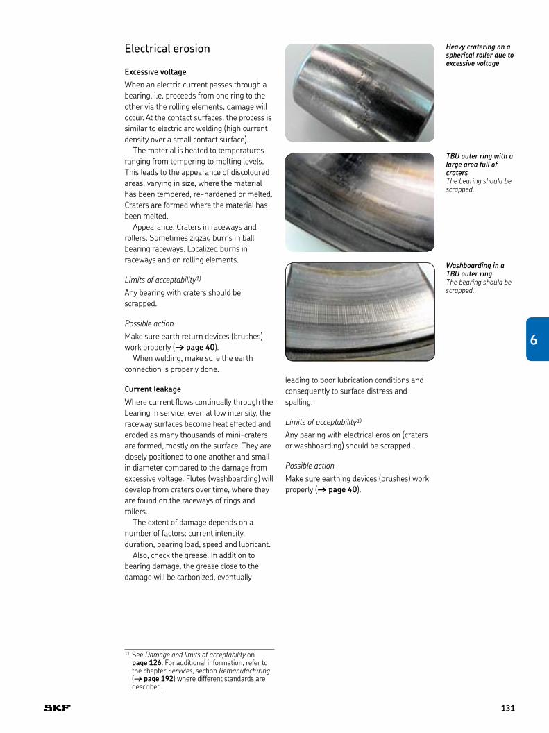
Heavy cratering on a spherical roller due to excessive voltage
Electrical erosion
Excessive voltageWhen an electric current passes through a bearing, i .e . proceeds from one ring to the other via the rolling elements, damage will occur . At the contact surfaces, the process is similar to electric arc welding (high current density over a small contact surface) .
The material is heated to temperatures ranging from tempering to melting levels . This leads to the appearance of discoloured areas, varying in size, where the material has been tempered, re-hardened or melted . Craters are formed where the material has been melted .
Appearance: Craters in raceways and rollers . Sometimes zigzag burns in ball bearing raceways . Localized burns in raceways and on rolling elements .
Limits of acceptability1)
Any bearing with craters should be scrapped .
Possible actionMake sure earth return devices (brushes) work properly († page 40) .
When welding, make sure the earth connection is properly done .
Current leakageWhere current flows continually through the bearing in service, even at low intensity, the raceway surfaces become heat effected and eroded as many thousands of mini-craters are formed, mostly on the surface . They are closely positioned to one another and small in diameter compared to the damage from excessive voltage . Flutes (washboarding) will develop from craters over time, where they are found on the raceways of rings and rollers .
The extent of damage depends on a number of factors: current intensity, duration, bearing load, speed and lubricant .
Also, check the grease . In addition to bearing damage, the grease close to the damage will be carbonized, eventually
TBU outer ring with a large area full of cratersThe bearing should be scrapped.
Washboarding in a TBU outer ringThe bearing should be scrapped.
leading to poor lubrication conditions and consequently to surface distress and spalling .
Limits of acceptability1)
Any bearing with electrical erosion (craters or washboarding) should be scrapped .
Possible actionMake sure earthing devices (brushes) work properly († page 40) .
1) See Damage and limits of acceptability on page 126 . For additional information, refer to the chapter Services, section Remanufacturing († page 192) where different standards are described .
6
131
Plastic deformation
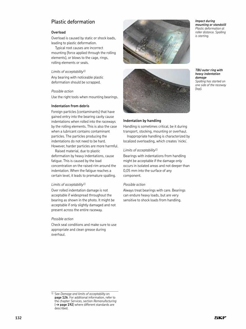
OverloadOverload is caused by static or shock loads, leading to plastic deformation .
Typical root causes are incorrect mounting (force applied through the rolling elements), or blows to the cage, rings, rolling elements or seals .
Limits of acceptability1)
Any bearing with noticeable plastic deformation should be scrapped .
Possible actionUse the right tools when mounting bearings .
Indentation from debrisForeign particles (contaminants) that have gained entry into the bearing cavity cause indentations when rolled into the raceways by the rolling elements . This is also the case when a lubricant contains contaminant particles . The particles producing the indentations do not need to be hard . However, harder particles are more harmful .
Raised material, due to plastic deformation by heavy indentations, cause fatigue . This is caused by the load concentration on the raised rim around the indentation . When the fatigue reaches a certain level, it leads to premature spalling .
Limits of acceptability1)
Over rolled indentation damage is not acceptable if widespread throughout the bearing as shown in the photo . It might be acceptable if only slightly damaged and not present across the entire raceway .
Possible actionCheck seal conditions and make sure to use appropriate and clean grease during overhaul .
Impact during mounting or standstillPlastic deformation at roller distance. Spalling is starting.
TBU outer ring with heavy indentation damageSpalling has started on one side of the raceway (top).
Indentation by handlingHandling is sometimes critical, be it during transport, stocking, mounting or overhaul .
Inappropriate handling is characterized by localized overloading, which creates ‘nicks’ .
Limits of acceptability1)
Bearings with indentations from handling might be acceptable if the damage only occurs in isolated areas and not deeper than 0,05 mm into the surface of any component .
Possible actionAlways treat bearings with care . Bearings can endure heavy loads, but are very sensitive to shock loads from handling .
1) See Damage and limits of acceptability on page 126 . For additional information, refer to the chapter Services, section Remanufacturing († page 192) where different standards are described .
132
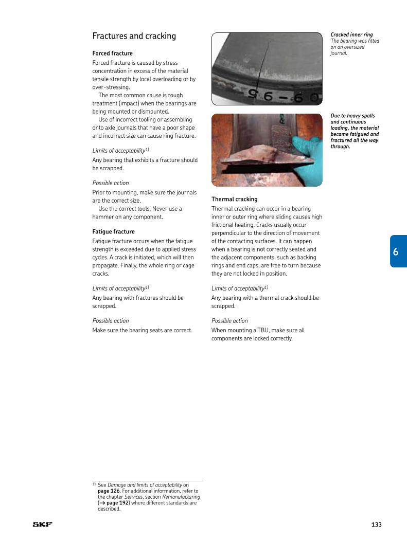
Cracked inner ringThe bearing was fitted on an oversized journal.
Fractures and cracking
Forced fractureForced fracture is caused by stress concentration in excess of the material tensile strength by local overloading or by over-stressing .
The most common cause is rough treatment (impact) when the bearings are being mounted or dismounted .
Use of incorrect tooling or assembling onto axle journals that have a poor shape and incorrect size can cause ring fracture .
Limits of acceptability1)
Any bearing that exhibits a fracture should be scrapped .
Possible actionPrior to mounting, make sure the journals are the correct size .
Use the correct tools . Never use a hammer on any component .
Fatigue fractureFatigue fracture occurs when the fatigue strength is exceeded due to applied stress cycles . A crack is initiated, which will then propagate . Finally, the whole ring or cage cracks .
Limits of acceptability1)
Any bearing with fractures should be scrapped .
Possible actionMake sure the bearing seats are correct .
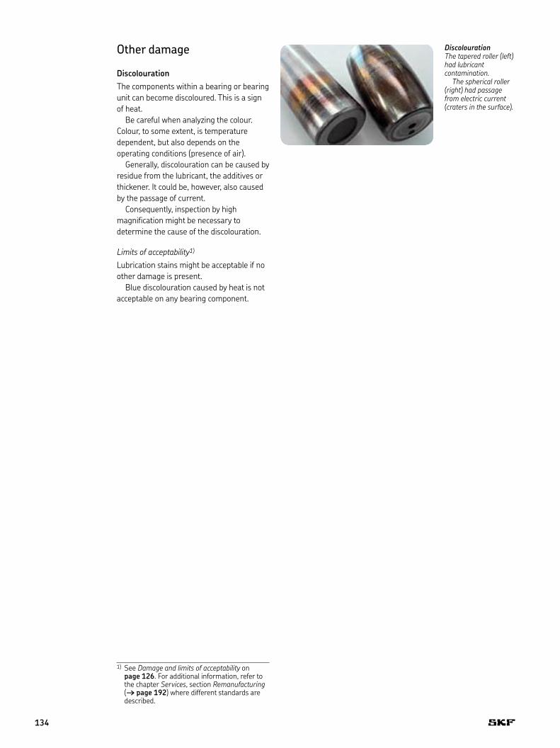
Due to heavy spalls and continuous loading, the material became fatigued and fractured all the way through.
Thermal crackingThermal cracking can occur in a bearing inner or outer ring where sliding causes high frictional heating . Cracks usually occur perpendicular to the direction of movement of the contacting surfaces . It can happen when a bearing is not correctly seated and the adjacent components, such as backing rings and end caps, are free to turn because they are not locked in position .
Limits of acceptability1)
Any bearing with a thermal crack should be scrapped .
Possible actionWhen mounting a TBU, make sure all components are locked correctly .
1) See Damage and limits of acceptability on page 126 . For additional information, refer to the chapter Services, section Remanufacturing († page 192) where different standards are described .
6
133
Other damage
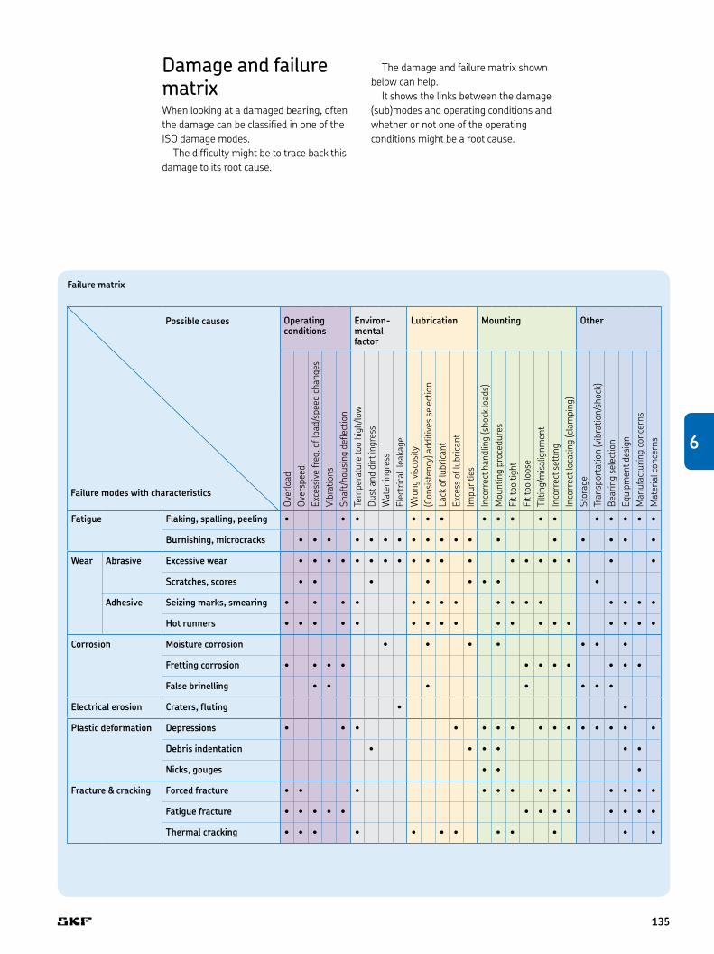
DiscolourationThe components within a bearing or bearing unit can become discoloured . This is a sign of heat .
Be careful when analyzing the colour . Colour, to some extent, is temperature dependent, but also depends on the operating conditions (presence of air) .
Generally, discolouration can be caused by residue from the lubricant, the additives or thickener . It could be, however, also caused by the passage of current .
Consequently, inspection by high magnification might be necessary to determine the cause of the discolouration .
Limits of acceptability1)
Lubrication stains might be acceptable if no other damage is present .
Blue discolouration caused by heat is not acceptable on any bearing component .
DiscolourationThe tapered roller (left) had lubricant contamination.
The spherical roller (right) had passage from electric current (craters in the surface).
1) See Damage and limits of acceptability on page 126 . For additional information, refer to the chapter Services, section Remanufacturing († page 192) where different standards are described .
134
Damage and failure matrixWhen looking at a damaged bearing, often the damage can be classified in one of the ISO damage modes .
The difficulty might be to trace back this damage to its root cause .
Operating conditions
Environ-mental factor
Lubrication Mounting Other
Over
load
Over
spee
dEx
cess
ive
freq
. of l
oad/
spee
d ch
ange
sVi
brat
ions
Shaf
t/ho
usin
g de
flect
ion
Tem
pera
ture
too
high
/low
Dus
t and
dirt
ingr
ess
Wat
er in
gres
sEl
ectr
ical
leak
age
Wro
ng v
isco
sity
(Con
sist
ency
) add
itive
s se
lect
ion
Lack
of l
ubric
ant
Exce
ss o
f lub
rican
tIm
purit
ies
Inco
rrec
t han
dlin
g (s
hock
load
s)M
ount
ing
proc
edur
esFi
t too
tigh
tFi
t too
loos
eTi
lting
/mis
alig
nmen
tIn
corr
ect s
ettin
gIn
corr
ect l
ocat
ing
(cla
mpi
ng)
Stor
age
Tran
spor
tatio
n (v
ibra
tion/
shoc
k)Be
arin
g se
lect
ion
Equi
pmen
t des
ign
Man
ufac
turin
g co
ncer
nsM
ater
ial c
once
rns
Fatigue Flaking, spalling, peeling • • • • • • • • • • • • • • • •
Burnishing, microcracks • • • • • • • • • • • • • • • • • •
Wear Abrasive Excessive wear • • • • • • • • • • • • • • • • • • •
Scratches, scores • • • • • • • •
Adhesive Seizing marks, smearing • • • • • • • • • • • • • • • •
Hot runners • • • • • • • • • • • • • • • • • •
Corrosion Moisture corrosion • • • • • • •
Fretting corrosion • • • • • • • • • • •
False brinelling • • • • • • •
Electrical erosion Craters, fluting • •
Plastic deformation Depressions • • • • • • • • • • • • • • •
Debris indentation • • • • • •
Nicks, gouges • • •
Fracture & cracking Forced fracture • • • • • • • • • • • • •
Fatigue fracture • • • • • • • • • • • • •
Thermal cracking • • • • • • • • • • • •
Possible causes
Failure modes with characteristics
The damage and failure matrix shown below can help .
It shows the links between the damage (sub)modes and operating conditions and whether or not one of the operating conditions might be a root cause .
Failure matrix
6
135
® SKF, AMPEP, @PTITUDE, AXLETRONIC, EASYRAIL, INSOCOAT, MRC, MULTILOG are registered trademarks of the SKF Group .
All other trademarks are the property of their respective owner .
© SKF Group 2012The contents of this publication are the copyright of the publisher and may not be reproduced (even extracts) unless prior written permission is granted . Every care has been taken to ensure the accuracy of the information contained in this publication but no liability can be accepted for any loss or damage whether direct, indirect or consequential arising out of the use of the information contained herein .
PUB 42/P2 12790 EN · 2012
Certain image(s) used under license from Shutterstock .com
Bearings and unitsSeals Lubrication
systems
Mechatronics Services
The Power of Knowledge Engineering
Drawing on five areas of competence and application-specific expertise amassed over more than 100 years, SKF brings innovative solutions to OEMs and production facilities in every major industry world-wide. These five competence areas include bearings and units, seals, lubrication systems, mechatronics (combining mechanics and electronics into intelligent systems), and a wide range of services, from 3-D computer modelling to advanced condition monitoring and reliability and asset management systems. A global presence provides SKF customers uniform quality standards and worldwide product availability.
ReferencesKerry, M., Peterson, L., Cagnasso, R.: [26] An Atlas of railway axle bearing defects including guidelines on how to examine bearings and overhaul practice. SKF (2008).
www.railways.skf.com