Embed Size (px)
Citation preview

Project Name : Sabaa Alboor 432
Site : Sabaa Alboor, Baghdad
Calculation Sheet (Bearing Wall)


PLAN


Solid Slab Design

fc' = 300 ksc. Live Load = 200 kg./m.2
fy = 4,000 ksc. Finishing = 15 kg./m.2
Covering = 2.50 cm.Thickness Asx/m. Asy/m.
(cm.) Lx(m.) Ly(m.) Mux(t.m) Muy(t.m)S0 16.00 5.60 6.65 Two way 1.567 1.236S1 12.00 4.05 5.90 Two way 0.902 0.546S2 12.00 3.25 3.79 Two way 0.435 0.352S3 12.00 1.40 - One way 0.402 -
SerialSize (Max.)
TypeMoment
Wire Mesh(Top&Bott.)
Solid Slab Design List
DB 10 mm. @ 0.20 m.
Remark : Use Bottom As Along Short Span
DB 10 mm. @ 0.20 m.
DB 10 mm. @ 0.20 m.
DB 10 mm. @ 0.20 m.

Wall Panel Design [WP1-WP4]

INPUT DATA:
fcu = 300 kg/cm²
fy = 4000 kg/cm²
Pu 87.084 tons
h 0.125 m.
Lu 3.2 m.
S 2.95 m.
Bearing wide (t) 5.9 m.
wall length (b) 5.9 m.
1‐Check of thicness (h)
h lu/25 or 12 cm.
L/25 = 0.128 m < h ok
2‐ Check of bearing strength of concrete
Area of bearing (A1) = h * t 0.76 m.²
Bearing capacity = (0.67*fc/δc *A1) 1011.97 ton > Pu ok
3‐ Calculate design strengthnof wall
Effective horizontal length of wall
Minimum of
Design of Bearing Wall (Calculation Sheet)
S = 2.95 cm. Governs
t+4h = 6.41 cm.
K = 0.80
0.35*fcuAg ( 1 ‐ ( k lu / ( 32h ) ^2 ) ) 193.28 ton > Pu ok
4‐ Determine Reinforcement
Virtical As = 6.40 cm.²/m
Horizontal As = 3.84 cm.²/m
Maximum spacing for vertical RFT.
25 cm
Maximum spacing for Horizontal RFT.
20 cm
15*d
Use Reiforcement
No. /m Diameter
Vertical Asv 5 Ø 10
Horizontal Ash 7 Ø 10
WP1‐1st
C.D.P (Concrete design program)

INPUT DATA:
fcu = 300 kg/cm²
fy = 4000 kg/cm²
Pu 65.313 tons
h 0.125 m.
Lu 3.2 m.
S 2.95 m.
Bearing wide (t) 5.9 m.
wall length (b) 5.9 m.
1‐Check of thicness (h)
h lu/25 or 12 cm.
L/25 = 0.128 m < h ok
2‐ Check of bearing strength of concrete
Area of bearing (A1) = h * t 0.76 m.²
Bearing capacity = (0.67*fc/δc *A1) 1011.97 ton > Pu ok
3‐ Calculate design strengthnof wall
Effective horizontal length of wall
Minimum of
Design of Bearing Wall (Calculation Sheet)
S = 2.95 cm. Governs
t+4h = 6.41 cm.
K = 0.80
0.35*fcuAg ( 1 ‐ ( k lu / ( 32h ) ^2 ) ) 193.28 ton > Pu ok
4‐ Determine Reinforcement
Virtical As = 6.40 cm.²/m
Horizontal As = 3.84 cm.²/m
Maximum spacing for vertical RFT.
25 cm
Maximum spacing for Horizontal RFT.
20 cm
15*d
Use Reiforcement
No. /m Diameter
Vertical Asv 5 Ø 10
Horizontal Ash 7 Ø 10
WP1‐2nd
C.D.P (Concrete design program)

INPUT DATA:
fcu = 300 kg/cm²
fy = 4000 kg/cm²
Pu 43.542 tons
h 0.125 m.
Lu 3.2 m.
S 2.95 m.
Bearing wide (t) 5.9 m.
wall length (b) 5.9 m.
1‐Check of thicness (h)
h lu/25 or 12 cm.
L/25 = 0.128 m < h ok
2‐ Check of bearing strength of concrete
Area of bearing (A1) = h * t 0.76 m.²
Bearing capacity = (0.67*fc/δc *A1) 1011.97 ton > Pu ok
3‐ Calculate design strengthnof wall
Effective horizontal length of wall
Minimum of
Design of Bearing Wall (Calculation Sheet)
S = 2.95 cm. Governs
t+4h = 6.41 cm.
K = 0.80
0.35*fcuAg ( 1 ‐ ( k lu / ( 32h ) ^2 ) ) 193.28 ton > Pu ok
4‐ Determine Reinforcement
Virtical As = 6.40 cm.²/m
Horizontal As = 3.84 cm.²/m
Maximum spacing for vertical RFT.
25 cm
Maximum spacing for Horizontal RFT.
20 cm
15*d
Use Reiforcement
No. /m Diameter
Vertical Asv 5 Ø 10
Horizontal Ash 7 Ø 10
WP1‐3rd
C.D.P (Concrete design program)

INPUT DATA:
fcu = 300 kg/cm²
fy = 4000 kg/cm²
Pu 21.771 tons
h 0.125 m.
Lu 3.2 m.
S 2.95 m.
Bearing wide (t) 5.9 m.
wall length (b) 5.9 m.
1‐Check of thicness (h)
h lu/25 or 12 cm.
L/25 = 0.128 m < h ok
2‐ Check of bearing strength of concrete
Area of bearing (A1) = h * t 0.76 m.²
Bearing capacity = (0.67*fc/δc *A1) 1011.97 ton > Pu ok
3‐ Calculate design strengthnof wall
Effective horizontal length of wall
Minimum of
Design of Bearing Wall (Calculation Sheet)
S = 2.95 cm. Governs
t+4h = 6.41 cm.
K = 0.80
0.35*fcuAg ( 1 ‐ ( k lu / ( 32h ) ^2 ) ) 193.28 ton > Pu ok
4‐ Determine Reinforcement
Virtical As = 6.40 cm.²/m
Horizontal As = 3.84 cm.²/m
Maximum spacing for vertical RFT.
25 cm
Maximum spacing for Horizontal RFT.
20 cm
15*d
Use Reiforcement
No. /m Diameter
Vertical Asv 5 Ø 10
Horizontal Ash 7 Ø 10
WP1‐4th
C.D.P (Concrete design program)

INPUT DATA:
fcu = 300 kg/cm²
fy = 4000 kg/cm²
Pu 32.256 tons
h 0.10 m.
Lu 3.2 m.
S 2.025 m.
Bearing wide (t) 4.05 m.
wall length (b) 4.05 m.
1‐Check of thicness (h)
h lu/25 or 12 cm.
L/25 = 0.128 m < h ok
2‐ Check of bearing strength of concrete
Area of bearing (A1) = h * t 0.52 m.²
Bearing capacity = (0.67*fc/δc *A1) 694.66 ton > Pu ok
3‐ Calculate design strengthnof wall
Effective horizontal length of wall
Minimum of
Design of Bearing Wall (Calculation Sheet)
S = 2.03 cm. Governs
t+4h = 4.56 cm.
K = 0.80
0.35*fcuAg ( 1 ‐ ( k lu / ( 32h ) ^2 ) ) 132.68 ton > Pu ok
4‐ Determine Reinforcement
Virtical As = 6.40 cm.²/m
Horizontal As = 3.84 cm.²/m
Maximum spacing for vertical RFT.
25 cm
Maximum spacing for Horizontal RFT.
20 cm
15*d
Use Reiforcement
No. /m Diameter
Vertical Asv 5 Ø 10
Horizontal Ash 7 Ø 10
WP2‐1st
C.D.P (Concrete design program)

INPUT DATA:
fcu = 300 kg/cm²
fy = 4000 kg/cm²
Pu 21.504 tons
h 0.10 m.
Lu 3.2 m.
S 2.025 m.
Bearing wide (t) 4.05 m.
wall length (b) 4.05 m.
1‐Check of thicness (h)
h lu/25 or 12 cm.
L/25 = 0.128 m < h ok
2‐ Check of bearing strength of concrete
Area of bearing (A1) = h * t 0.52 m.²
Bearing capacity = (0.67*fc/δc *A1) 694.66 ton > Pu ok
3‐ Calculate design strengthnof wall
Effective horizontal length of wall
Minimum of
Design of Bearing Wall (Calculation Sheet)
S = 2.03 cm. Governs
t+4h = 4.56 cm.
K = 0.80
0.35*fcuAg ( 1 ‐ ( k lu / ( 32h ) ^2 ) ) 132.68 ton > Pu ok
4‐ Determine Reinforcement
Virtical As = 6.40 cm.²/m
Horizontal As = 3.84 cm.²/m
Maximum spacing for vertical RFT.
25 cm
Maximum spacing for Horizontal RFT.
20 cm
15*d
Use Reiforcement
No. /m Diameter
Vertical Asv 5 Ø 10
Horizontal Ash 7 Ø 10
WP2‐2nd
C.D.P (Concrete design program)

INPUT DATA:
fcu = 300 kg/cm²
fy = 4000 kg/cm²
Pu 10.752 tons
h 0.10 m.
Lu 3.2 m.
S 2.025 m.
Bearing wide (t) 4.05 m.
wall length (b) 4.05 m.
1‐Check of thicness (h)
h lu/25 or 12 cm.
L/25 = 0.128 m < h ok
2‐ Check of bearing strength of concrete
Area of bearing (A1) = h * t 0.52 m.²
Bearing capacity = (0.67*fc/δc *A1) 694.66 ton > Pu ok
3‐ Calculate design strengthnof wall
Effective horizontal length of wall
Minimum of
Design of Bearing Wall (Calculation Sheet)
S = 2.03 cm. Governs
t+4h = 4.56 cm.
K = 0.80
0.35*fcuAg ( 1 ‐ ( k lu / ( 32h ) ^2 ) ) 132.68 ton > Pu ok
4‐ Determine Reinforcement
Virtical As = 6.40 cm.²/m
Horizontal As = 3.84 cm.²/m
Maximum spacing for vertical RFT.
25 cm
Maximum spacing for Horizontal RFT.
20 cm
15*d
Use Reiforcement
No. /m Diameter
Vertical Asv 5 Ø 10
Horizontal Ash 7 Ø 10
WP2‐3rd
C.D.P (Concrete design program)

INPUT DATA:
fcu = 300 kg/cm²
fy = 4000 kg/cm²
Pu 13.95 tons
h 0.10 m.
Lu 3.2 m.
S 1.2 m.
Bearing wide (t) 2.4 m.
wall length (b) 2.4 m.
1‐Check of thicness (h)
h lu/25 or 12 cm.
L/25 = 0.128 m < h ok
2‐ Check of bearing strength of concrete
Area of bearing (A1) = h * t 0.29 m.²
Bearing capacity = (0.67*fc/δc *A1) 385.92 ton > Pu ok
3‐ Calculate design strengthnof wall
Effective horizontal length of wall
Minimum of
Design of Bearing Wall (Calculation Sheet)
S = 1.20 cm. Governs
t+4h = 2.88 cm.
K = 0.80
0.35*fcuAg ( 1 ‐ ( k lu / ( 32h ) ^2 ) ) 67.20 ton > Pu ok
4‐ Determine Reinforcement
Virtical As = 6.00 cm.²/m
Horizontal As = 3.60 cm.²/m
Maximum spacing for vertical RFT.
25 cm
Maximum spacing for Horizontal RFT.
20 cm
15*d
Use Reiforcement
No. /m Diameter
Vertical Asv 4 Ø 10
Horizontal Ash 7 Ø 10
WP3‐1st
C.D.P (Concrete design program)

INPUT DATA:
fcu = 300 kg/cm²
fy = 4000 kg/cm²
Pu 9.3 tons
h 0.10 m.
Lu 3.2 m.
S 1.2 m.
Bearing wide (t) 2.4 m.
wall length (b) 2.4 m.
1‐Check of thicness (h)
h lu/25 or 12 cm.
L/25 = 0.128 m < h ok
2‐ Check of bearing strength of concrete
Area of bearing (A1) = h * t 0.29 m.²
Bearing capacity = (0.67*fc/δc *A1) 385.92 ton > Pu ok
3‐ Calculate design strengthnof wall
Effective horizontal length of wall
Minimum of
Design of Bearing Wall (Calculation Sheet)
S = 1.20 cm. Governs
t+4h = 2.88 cm.
K = 0.80
0.35*fcuAg ( 1 ‐ ( k lu / ( 32h ) ^2 ) ) 67.20 ton > Pu ok
4‐ Determine Reinforcement
Virtical As = 6.00 cm.²/m
Horizontal As = 3.60 cm.²/m
Maximum spacing for vertical RFT.
25 cm
Maximum spacing for Horizontal RFT.
20 cm
15*d
Use Reiforcement
No. /m Diameter
Vertical Asv 4 Ø 10
Horizontal Ash 7 Ø 10
WP3‐2nd
C.D.P (Concrete design program)

INPUT DATA:
fcu = 300 kg/cm²
fy = 4000 kg/cm²
Pu 4.65 tons
h 0.10 m.
Lu 3.2 m.
S 1.2 m.
Bearing wide (t) 2.4 m.
wall length (b) 2.4 m.
1‐Check of thicness (h)
h lu/25 or 12 cm.
L/25 = 0.128 m < h ok
2‐ Check of bearing strength of concrete
Area of bearing (A1) = h * t 0.29 m.²
Bearing capacity = (0.67*fc/δc *A1) 385.92 ton > Pu ok
3‐ Calculate design strengthnof wall
Effective horizontal length of wall
Minimum of
Design of Bearing Wall (Calculation Sheet)
S = 1.20 cm. Governs
t+4h = 2.88 cm.
K = 0.80
0.35*fcuAg ( 1 ‐ ( k lu / ( 32h ) ^2 ) ) 67.20 ton > Pu ok
4‐ Determine Reinforcement
Virtical As = 6.00 cm.²/m
Horizontal As = 3.60 cm.²/m
Maximum spacing for vertical RFT.
25 cm
Maximum spacing for Horizontal RFT.
20 cm
15*d
Use Reiforcement
No. /m Diameter
Vertical Asv 4 Ø 10
Horizontal Ash 7 Ø 10
WP3‐3rd
C.D.P (Concrete design program)

INPUT DATA:
fcu = 300 kg/cm²
fy = 4000 kg/cm²
Pu 7.12 tons
h 0.10 m.
Lu 3.2 m.
S 1.225 m.
Bearing wide (t) 2.45 m.
wall length (b) 2.45 m.
1‐Check of thicness (h)
h lu/25 or 12 cm.
L/25 = 0.128 m < h ok
2‐ Check of bearing strength of concrete
Area of bearing (A1) = h * t 0.29 m.²
Bearing capacity = (0.67*fc/δc *A1) 393.96 ton > Pu ok
3‐ Calculate design strengthnof wall
Effective horizontal length of wall
Minimum of
Design of Bearing Wall (Calculation Sheet)
S = 1.23 cm. Governs
t+4h = 2.93 cm.
K = 0.80
0.35*fcuAg ( 1 ‐ ( k lu / ( 32h ) ^2 ) ) 68.60 ton > Pu ok
4‐ Determine Reinforcement
Virtical As = 6.00 cm.²/m
Horizontal As = 3.60 cm.²/m
Maximum spacing for vertical RFT.
25 cm
Maximum spacing for Horizontal RFT.
20 cm
15*d
Use Reiforcement
No. /m Diameter
Vertical Asv 4 Ø 10
Horizontal Ash 7 Ø 10
WP4‐1st
C.D.P (Concrete design program)

INPUT DATA:
fcu = 300 kg/cm²
fy = 4000 kg/cm²
Pu 4.747 tons
h 0.10 m.
Lu 3.2 m.
S 1.225 m.
Bearing wide (t) 2.45 m.
wall length (b) 2.45 m.
1‐Check of thicness (h)
h lu/25 or 12 cm.
L/25 = 0.128 m < h ok
2‐ Check of bearing strength of concrete
Area of bearing (A1) = h * t 0.29 m.²
Bearing capacity = (0.67*fc/δc *A1) 393.96 ton > Pu ok
3‐ Calculate design strengthnof wall
Effective horizontal length of wall
Minimum of
Design of Bearing Wall (Calculation Sheet)
S = 1.23 cm. Governs
t+4h = 2.93 cm.
K = 0.80
0.35*fcuAg ( 1 ‐ ( k lu / ( 32h ) ^2 ) ) 68.60 ton > Pu ok
4‐ Determine Reinforcement
Virtical As = 6.00 cm.²/m
Horizontal As = 3.60 cm.²/m
Maximum spacing for vertical RFT.
25 cm
Maximum spacing for Horizontal RFT.
20 cm
15*d
Use Reiforcement
No. /m Diameter
Vertical Asv 4 Ø 10
Horizontal Ash 7 Ø 10
WP4‐2nd
C.D.P (Concrete design program)

INPUT DATA:
fcu = 300 kg/cm²
fy = 4000 kg/cm²
Pu 2.373 tons
h 0.10 m.
Lu 3.2 m.
S 1.225 m.
Bearing wide (t) 2.45 m.
wall length (b) 2.45 m.
1‐Check of thicness (h)
h lu/25 or 12 cm.
L/25 = 0.128 m < h ok
2‐ Check of bearing strength of concrete
Area of bearing (A1) = h * t 0.29 m.²
Bearing capacity = (0.67*fc/δc *A1) 393.96 ton > Pu ok
3‐ Calculate design strengthnof wall
Effective horizontal length of wall
Minimum of
Design of Bearing Wall (Calculation Sheet)
S = 1.23 cm. Governs
t+4h = 2.93 cm.
K = 0.80
0.35*fcuAg ( 1 ‐ ( k lu / ( 32h ) ^2 ) ) 68.60 ton > Pu ok
4‐ Determine Reinforcement
Virtical As = 6.00 cm.²/m
Horizontal As = 3.60 cm.²/m
Maximum spacing for vertical RFT.
25 cm
Maximum spacing for Horizontal RFT.
20 cm
15*d
Use Reiforcement
No. /m Diameter
Vertical Asv 4 Ø 10
Horizontal Ash 7 Ø 10
WP4‐3rd
C.D.P (Concrete design program)

= 125 mm.
= 300 ksc.
Wall Panel Floor In Hight Steel Grade 60 = 4,000 ksc.
Ref. No. Ref. No. Floor (m.)
Plan
5.90
5.90
5.90
7,380.00
3.20 11,070.00DB 10 mm. @ 0.20 m.
DB 10 mm. @ 0.20 m.
Schedule of Wall Panel
Capacity (kg./m.) Horizontal Reinf.
WP101 1st WP1 3.20 14,760.00DB 10 mm. @ 0.20 m.
DB 10 mm. @ 0.20 m.
DB 10 mm. @ 0.20 m.
DB 10 mm. @ 0.20 m.
WP201 2nd WP1
Length
(m.)
5.90
Building Wall Design Table Thickness
WP1 Concrete Grade
Ult. Vert. Load Vertical Reinf.
Remark : Control Design by Use Max Load and Max Length
WP401 4th WP1 3.20 3,690.00DB 10 mm. @ 0.20 m.
DB 10 mm. @ 0.20 m.
WP301 3rd WP1 3.20
= 100 mm.
= 300 ksc.
Wall Panel Floor In Hight Steel Grade 60 = 4,000 ksc.
Ref. No. Ref. No. Floor (m.)
Plan
Schedule of Wall Panel
Building Wall Design Table Thickness
WP2 Concrete Grade
Ult. Vert. Load Vertical Reinf. Length
(m.)Capacity (kg./m.) Horizontal Reinf.
WP102 1st WP2 3.20 7,965.00DB 10 mm. @ 0.20 m.
4.05DB 10 mm. @ 0.20 m.
4.05DB 10 mm. @ 0.20 m.
WP302 3rd WP2 3.20 2,655.00DB 10 mm. @ 0.20 m.
4.05DB 10 mm. @ 0.20 m.
WP202 2nd WP2 3.20 5,310.00DB 10 mm. @ 0.20 m.
Remark : Control Design by Use Max Load and Max Length

= 100 mm.
= 300 ksc.
Wall Panel Floor In Hight Steel Grade 60 = 4,000 ksc.
Ref. No. Ref. No. Floor (m.)
Plan
Building Wall Design Table Thickness
WP3 Concrete Grade
Schedule of Wall Pannel
Ult. Vert. Load Vertical Reinf. Length
(m.)Capacity (kg./m.) Horizontal Reinf.
WP103 1st WP3 3.20 5,812.50
3.20 1,937.50DB 10 mm. @ 0.25 m.
DB 10 mm. @ 0.25 m.2.40
DB 10 mm. @ 0.25 m.
WP203 2nd WP3 3.20 3,875.00DB 10 mm. @ 0.25 m.
2.40
Remark : Control Design by Use Max Load and Max Length
2.40DB 10 mm. @ 0.25 m.
DB 10 mm. @ 0.25 m.
WP303 3rd WP3

= 100 mm.
= 300 ksc.
Wall Panel Floor In Hight Steel Grade 60 = 4,000 ksc.
Ref. No. Ref. No. Floor (m.)
Plan
Schedule of Wall Panel
Vertical Reinf. Length
(m.)Capacity (kg./m.) Horizontal Reinf.
WP104
Building Wall Design Table Thickness
WP4 Concrete Grade
Ult. Vert. Load
WP304 3rd WP4 3.20
1st WP4 3.20 2,906.25DB 10 mm. @ 0.25 m.
2.45DB 10 mm. @ 0.25 m.
WP204 2nd WP4 3.20 1,937.50DB 10 mm. @ 0.25 m.
2.45DB 10 mm. @ 0.25 m.
Remark : Control Design by Use Max Load and Max Length
968.75DB 10 mm. @ 0.25 m.
2.45DB 10 mm. @ 0.25 m.

Stair Design

INPUT DATA:
fcu= 300 kg/cm²
fy= 4000 kg/cm²
R 0.20 m.
S 0.3 m.
H .17 m.
Cover 0.025 m.
W 1.5 m.
L1 1.5 m.
L2 2.5 m.
L3 0.001 m.
Live load 0.30 t/m²
Dead Load 0.05 t/m²
1‐ Loads
Wu (Landing) = (1.4* OwL + 1.4*DL + 1.6 * LL) * W
Wu (Landing) = 1.718 t/m
Wu (Flight) = (1.4 * OwF /cos + 1.4*DL / cos + 1.6 * LL) * W
Wu (Flight) = 2.550 t/m
Design of stair (Calculation Sheet)
2‐ Flight
R1= 4.866 ton
R2 = 4.087 ton
X_Zero shear 2.092 m.
Mumax 4.645 m.t
3‐ Shear stength
10.7331 kg/cm²
qu = Qu/ b*d 2.3338 kg/cm²
4‐ Reinforcement
As min.= 3.1275 cm²
As = 10.2600 cm²
5‐ Details
As 10.00
ST1
C.D.P (Concrete design program)

Beam Design [BST & HEADER]

Design of Beams (Calculation Sheet) BST
INPUT DATA:
fy= 4000.00 kg/cm²
fcu= 300.00 kg/cm²
Mu(Moment)= 4.86 m.t
Vu(Shear)= 6.48 ton
Tu (Torsion)= 0.00 m.t
b = 12.50 cm
t = 45.00 cm
cover = 2.50 cm
d = 39.90 cm
CALCULATIONS:Flexure Design
1‐ Force Equilibrium
C = T 0.67 fcu b a / γc = fy As /γs
2‐ Moment Equilibrium
Mu = (C or T) ( d ‐ a/2 )
0.67 fcu/γc b (a)²/2 ‐ 0.67 fcu/γc b d (a) + Mu=0
a = 8.09 cm a 8.09 cm
As(Required) =( 0.67 fcu/γc b a) /( fy/γs)
As(Required) = 3.90 cm²
a/d 0.20 Ok > 0.1
CHECK OF ρ max.
µmax. = 0.01293 Table(4‐1)
Asmax=µmax. b d 6.45 cm² ok
CHECK OF ρ min.
As,min2 = 1.3*As_req. 5.07 cm²
As,min1 = 11/fy *(bd) 1.37 cm²
As,min3 = 0.25 or 0.15% (bd) 0.75 cm²
Asmin4= 1.54 cm²
As,min = 1.54 cm²
Area Steel Required
As = 3.90 cm²
εs = 0.003 * (d ‐ c ) / c
εs = 0.00883 Use 4 φ 12
Tension controlledTension‐controlled
1/2
C.D.P (Concrete design program)

qu =Qu / b.d 12.99 kg/cm²
qcu = 10.73 kg/cm²
qumax = 31.30 kg/cm² And less than 40 kg/cm²
qsu = qu ‐ 1/2 qcu 7.63 kg/cm²
Ast / b.s = qsu /(fy /γs)
Ast = 1.01 cm²
S = 22.01 cm
µmin1 = 0.40/fy = Ast/(b.S)
Smax1 = 48.25 cm
Smax2 =0.15 or 0.1 % * µ 53.62 cm
Smax3 = 20 cm 20.00 cm
Shear Design
Smax= 20.00 cm
Use Stirrup 5 φ 8 \m
Branch Number 2
2/2
C.D.P (Concrete design program)

Design of Beams (Calculation Sheet) Header
INPUT DATA:
fy= 4000.00 kg/cm²
fcu= 300.00 kg/cm²
Mu(Moment)= 3.53 m.t
Vu(Shear)= 4.52 ton
Tu (Torsion)= 0.00 m.t
b = 12.50 cm
t = 80.00 cm
cover = 2.40 cm
d = 76.00 cm
CALCULATIONS:Flexure Design
1‐ Force Equilibrium
C = T 0.67 fcu b a / γc = fy As /γs
2‐ Moment Equilibrium
Mu = (C or T) ( d ‐ a/2 )
0.67 fcu/γc b (a)²/2 ‐ 0.67 fcu/γc b d (a) + Mu=0
a = 7.60 cm a 7.60 cm
As(Required) =( 0.67 fcu/γc b a) /( fy/γs)
As(Required) = 3.66 cm²
a/d 0.10 Ok > 0.1
CHECK OF ρ max.
µmax. = 0.01293 Table(4‐1)
Asmax=µmax. b d 12.28 cm² ok
CHECK OF ρ min.
As,min2 = 1.3*As_req. 4.76 cm²
As,min1 = 11/fy *(bd) 2.61 cm²
As,min3 = 0.25 or 0.15% (bd) 1.43 cm²
Asmin4= 2.93 cm²
As,min = 2.93 cm²
Area Steel Required
As = 3.66 cm²
εs = 0.003 * (d ‐ c ) / c
εs = 0.06155 Use 2 φ 16
Tension controlledTension‐controlled
Header1/2
C.D.P (Concrete design program)

qu =Qu / b.d 4.76 kg/cm²
qcu = 10.73 kg/cm²
qumax = 31.30 kg/cm² And less than 40 kg/cm²
qsu = qu ‐ 1/2 qcu ‐0.61 kg/cm²
Ast / b.s = qsu /(fy /γs)
Ast = 1.01 cm²
S = Min. Stirrup cm
µmin1 = 0.40/fy = Ast/(b.S)
Smax1 = 48.25 cm
Smax2 =0.15 or 0.1 % * µ 53.62 cm
Smax3 = 20 cm 20.00 cm
Shear Design
Smax= 20.00 cm
Use Stirrup 5 φ 8 \m
Branch Number 2
Header 2/2
C.D.P (Concrete design program)

Mat Foundation Design

FOUNDATION CALCULATION SHEET
One-Stop Solution for Foundation
TITLE DESCRIPTION
PROJECT/JOB NO. 1-1
PROJECT/JOB NAME Sabaa Alboor 432
CLIENT NAME Sabaa
SITE NAME Sabaa Alboor, Baghdad
DOCUMENT NO.
REFERENCE NO.
STRUCTURE NAME Sabaa Alboor, Baghdad
LOAD COMBINATION GROUP
REV DATE DESCRIPTION PREP'D CHK'D APPR'D APPR'D
Copyright (c) GS E&C. All Rights Reserved

Page 1
Calculation Sheetof
Foundation
Project Na. : Sabaa Alboor 432
Project No. : 1-1
Client : Sabaa
FOUNDATION LISTSGroup Name No. Description No. Description
MAT1 1 F1
1/12/2555
Copyright (c) GS E&C. All Rights Reserved

Page 2
Calculation Sheetof
Foundation
Project Na. : Sabaa Alboor 432
Project No. : 1-1
Client : Sabaa
CONTENTS
1. GENERAL 1.1 CODE & STANDARD
1.2 MATERIALS & UNIT WEIGHT
1.3 SUBSOIL CONDITION & SAFETY FACTORS
1.4 LOAD COMBINATION
2. DRAWING 2.1 LOCATION PLAN & DETAIL SKETCH
3. FOUNDATION DATA 3.1 FOOTING AND SECTION DATA
3.2 PIER DATA
3.3 LOAD CASE
3.4 LOAD COMBINATION
4. CHECK OF STABILITY 4.1 CHECK OF SLIDING
4.2 CHECK OF OVERTURNING MOMENT
4.3 CHECK OF CONTACT PRESSURE
5. DESIGN OF FOOTING 5.1 DESIGN MOMENT AND SHEAR FORCE
5.2 REQUIRED REINFORCEMENT
5.3 ONE WAY SHEAR FORCE
5.4 TWO WAY SHEAR FORCE
1/12/2555
Copyright (c) GS E&C. All Rights Reserved

Page 3
Calculation Sheetof
Foundation
Project Na. : Sabaa Alboor 432
Project No. : 1-1
Client : Sabaa
1. GENERAL 1.1 CODE & STANDARD
Items Description
Design Code American Concrete Institute (ACI 318)
Horizontal Force for Wind UNIFORM BUILDING CODE (UBC-1997)
Horizontal Force for Seismic UNIFORM BUILDING CODE [UBC-1997]
Unit System Input : MKS, Output : IMPERIAL, Calculation Unit : IMPERIAL
1.2 MATERIALS & UNIT WEIGHT
Items Value (Input Unit system / Output Unit System)
Concrete (f'c : compressive strength)
Lean Concrete (Lf'c : compressive strength)
Rs (Soil unit weight)
Rc (Concrete unit weight)
Es (Steel Modulus of Elasticity)
Ec (Concrete Modulus of Elasticity)
- Soil Capacity
Items Value (Input Unit system / Output Unit System)
Soil Name Unit-01
Footing List F1
Qa (Soil Bearing Capacity)
Buoyancy Not Consider
WL (Water Label from the EL = 0) 0 mm 0 ft
FD (Frost Depth from the EL = 0) 0 mm 0 ft
Internal Friction Angle
Passive Soil Pressure Not Consider
Cu (Undrained cohesion)
1.3 SUBSOIL CONDITION & SAFETY FACTORS
Items Description (Input/Output)
Allowable Increase of Soil (Wind) 33.33 %
Allowable Increase of Soil (Seismic) 33.33 %
Allowable Increase of Soil (Test) 20 %
Safety factor against overturning for OVM1(FO1) 1.5
Safety factor against overturning for OVM2(FO2) 1.5
Safety factor against overturning for OVM3(FO3) 1.5
Safety factor against overturning for OVM4(FO4) 1.9
Safety factor against sliding for the SL1(FS1) 1.5
Safety factor against sliding for the SL2(FS2) 1.8
Safety factor against sliding for the SL3(FS3) 1.5
1/12/2555
Copyright (c) GS E&C. All Rights Reserved
Reinforcement (10M ~ 16M , yield strength)
Reinforcement (19M ~ , yield strength)
4267.003 psi
3413.602 psi
56893.370 psi
56893.370 psi
99.886 lb/ft3
149.829 lb/ft3
29015.620 ksi
3724.467 ksi
300.00 kgf/cm2
240.00 kgf/cm2
4000.00 kgf/cm2
4000.00 kgf/cm2
1.600 ton/m3
2.400 ton/m3
2.04 106 kgf/cm2
261856.00 kgf/cm2
Clay , 0 psf
1638.55 psf
0
8 tonf/m2

Page 4
Calculation Sheetof
Foundation
Project Na. : Sabaa Alboor 432
Project No. : 1-1
Client : Sabaa
Safety factor against sliding for the SL4(FS4) 1.5
.35
1.4 LOAD COMBINATION
Index Load Case Name Load Case Description
1 DL DEAD LOAD
2 LL LIVE LOAD
Comb . ID Load Combination for Reinforcement
1 1.4 DL + 1.7 LL
1/12/2555
Copyright (c) GS E&C. All Rights Reserved
Friction factor ()

2. DRAWING REFERENCE DWGSNO. DWG NO. DWG TITLE
N O T E S
* OUTPUT UNIT : mm
Sabaa Alboor 432 PROJECT
FOUNDATION LOCATION PLANSabaa Alboor, Baghdad
SQU
AD
CH
EC
K
PROCESS PIPING VESSELS STRUCT. ELEC. INST.
SCALE
AS SHOWN
JOB NO.
1-1
MICROFILM NO.
F1
1
A01
01
Z X
Y
1/12/2555 Page 5
Copyright (c) GS E&C. All Rights Reserved

OUTPUT UNIT : mm
1/12/2555 Page 6
Copyright (c) GS E&C. All Rights Reserved
REFERENCE DWGSNO. DWG NO. DWG TITLE
N O T E S
* OUTPUT UNIT : mm
Sabaa Alboor 432 PROJECT
FOUNDATION DETAIL FORF1
SQU
AD
CH
EC
K
PROCESS PIPING VESSELS STRUCT. ELEC. INST.
SCALE
AS SHOWN
JOB NO.
1-1
MICROFILM NO.
REV. DATE DESCRIPTION DRWNCHKDAPPD APPD APPD
1
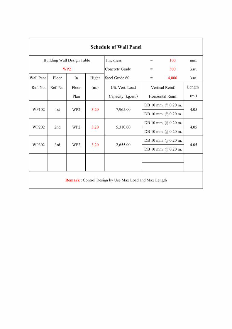
LC FOOTING
LC
FOO
TIN
G
5000x2
2025
x2
10000
4050
FOUNDATION PLAN
1/12/2555 Page 7
Copyright (c) GS E&C. All Rights Reserved

REFERENCE DWGSNO. DWG NO. DWG TITLE
N O T E S
* OUTPUT UNIT : mm
Sabaa Alboor 432 PROJECT
FOUNDATION DETAIL FORF1
SQU
AD
CH
EC
K
PROCESS PIPING VESSELS STRUCT. ELEC. INST.
SCALE
AS SHOWN
JOB NO.
1-1
MICROFILM NO.
REV. DATE DESCRIPTION DRWNCHKDAPPD APPD APPD
LC FOOTING
16M@250
16M
@25
0
3 TY
P.
22M@150
22M
@15
0
TOP BOTTOM
REINFORCEMENT PLAN
1/12/2555 Page 8
Copyright (c) GS E&C. All Rights Reserved
Page 11
Calculation Sheetof
Foundation
Project Na. : Sabaa Alboor 432
Project No. : 1-1
Client : Sabaa
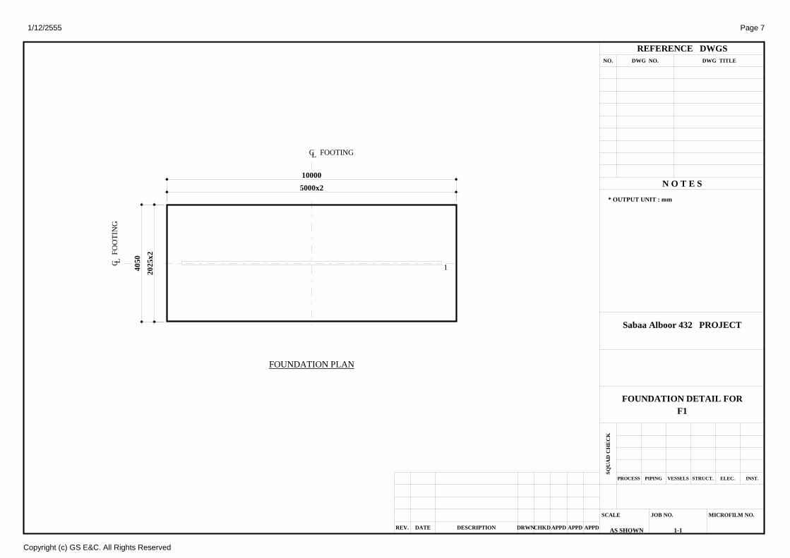
3. FOUNDATION DATA 3.1 FOOTING AND SECTION DATA
30 0
32.81
13.2
9
The Origin coordinate
The Center of gravity (0,0) ft 1.97
10.5
1.64
( ft ) Ft. Name F1
Ft. Type
Area
Ft. Thickness 1.97 ft
Ft. Volume
Ft. Weight 128.576 kips
Soil Height 1.64 ft
Soil Volume
Soil Weight 69.448 kips
Buoyancy Not Consider
Self Weight (except Pr.SW) 198.024 kips
Section Data
( ft ) Ft.Name Direction Ft. Volume Soil Volume Pier Wt
F1 All Direct
Sec.Name Section Area Ft. Weight Soil Weight Total Weight
S1
3.2 PIER DATAOff X , Off Y is offset position from the Center of the footing
If Pier Shape is Circle or Circle wall, Pl is a Diameter. and Pw is a Inner Diameter
Area is pier concrete area
Weight is pier and inner soil weight in case circle wall except Tank1 Type(Circle Ring Footing Shape)
Unit( Length : ft , Weight : kips , Area : ft2 )
Ft.Name Pr.Name Shape Pl Pw Ph Area Weight Off X Off YF1 1 Rectangle 29.528 0.410 10.499 19.048 0.000 0.000
3.3 LOAD CASE
Input the point loads in the global coordinate system direction. Positive directions of moments (shown in the sketch) are based on the right hand rule.
Fx
FyFz
Mx
MyMz
1/12/2555
Copyright (c) GS E&C. All Rights Reserved
MAT
435.939 ft2
858.146 ft3
695.275 ft3
435.939 ft2
858.146 ft3
128.576 kips
695.275 ft3
69.448 kips
19.048 kips
217.072 kips
12.109

Page 12
Calculation Sheetof
Foundation
Project Na. : Sabaa Alboor 432
Project No. : 1-1
Client : Sabaa
Index Load Case Name Load Case Description
1 DL DEAD LOAD
2 LL LIVE LOAD
Unit( kips , kips-ft )
Ft.Name Pr.Name Load Case Fx Fy Fz Mx My
F11
1 0 0 -110.23 0 0
2 0 0 -286.61 0 0
Footing SW 0.000 0.000 -198.024 0.000 0.000
3.4 LOAD COMBINATION
In Pier Top
without Self Weight
In Footing Bottom
with Pier Self Weight,
But without Footing Self Weight,
In Footing Bottom Center
with Pier & Footing Self Weight & Soil Weight,
Case PileType
in centroid of Pile Group
Case NonPileType
in centroid of Footing
3.4.1 Load Combination in Pier Top (Without SW)Unit( kips , kips-ft )
Ft.Name Pr.Name L.Comb.1 1 0.000 0.000 -641.555 0.000 0.000
3.4.2 Load Combination in Footing Bottom (With Pier SW)Unit( kips , kips-ft )
Ft.Name Pr.Name L.Comb.1 1 0.000 0.000 -641.555 0.000 0.000
3.4.3 Load Combination in Footing Bottom Center (With Pier & Footing SW)
Load Combination of Elastic Condition
There is no Load Combination
Load Combination of Ultimate Condition
- C.G. of Load is coordinate from left bottom. Unit : ft Unit( kips , kips-ft )
Ft.Name Sec.Na L.Comb. C.G. of Loads
S1 1 0.000 0.000 -641.555 0.000 0.000 16.4 , 6.6
1/12/2555
Copyright (c) GS E&C. All Rights Reserved
Fx Fy Fz Mx MyF1
Fx Fy Fz Mx MyF1
Fx Fy Fz Mx My
F1

Page 13
Calculation Sheetof
Foundation
Project Na. : Sabaa Alboor 432
Project No. : 1-1
Client : Sabaa
4. CHECK OF STABILITYThere is no Static LoadCombination
1/12/2555
Copyright (c) GS E&C. All Rights Reserved
Page 14
Calculation Sheetof
Foundation
Project Na. : Sabaa Alboor 432
Project No. : 1-1
Client : Sabaa
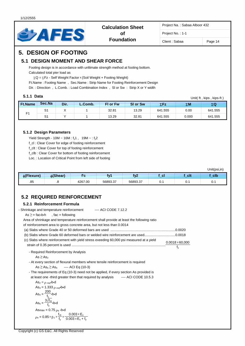
5. DESIGN OF FOOTING 5.1 DESIGN MOMENT AND SHEAR FORCE
Footing design is in accordance with unltimate strength method at footing bottom.
Calculated total pier load as
Q = Fz - Self Weight Factor (Soil Weight + Footing Weight)
Ft.Name : Footing Name , Sec.Name : Strip Name for Footing Reinforcement Design
Dir. : Direction , L.Comb. : Load Combination Index , Sl or Sw : Strip X or Y width
5.1.1 Data Unit( ft , kips , kips-ft )
Ft.Name Sec.Na Dir. L.Comb. Fl or Fw Sl or Sw
F1S1 X 1 32.81 13.29 641.555 0.00 641.555
S1 Y 1 13.29 32.81 641.555 0.000 641.555
5.1.2 Design Parameters
Yield Strength - 10M ~ 16M : fy1 , 19M ~ : fy2
f_cl : Clear Cover for edge of footing reinforcement
f_clt : Clear Cover for top of footing reinforcement
f_clb : Clear Cover for bottom of footing reinforcement
Loc. : Location of Critical Point from left side of footing
Unit(psi,in)
f'c fy1 fy2 f_cl f_clt f_clb
.85 .8 4267.00 56893.37 56893.37 0.1 0.1
5.2 REQUIRED REINFORCEMENT 5.2.1 Reinforcement Formula
- Shrinkage and temperature reinforcement ---- ACI CODE 7.12.2
As = fac b h , fac = following
Area of shrinkage and temperature reinforcement shall provide at least the following ratio
of reinforcement area to gross concrete area, but not less than 0.0014
(a) Slabs where Grade 40 or 50 deformed bars are used .....................................................................0.0020
(b) Slabs where Grade 60 deformed bars or welded wire reinforcement are used.................................0.0018
(c) Slabs where reinforcement with yield stress exeeding 60,000 psi measured at a yield
strain of 0.35 percent is used ....................................................................................................0.0018 60,000
fy- Required Reinforcement by Analysis
As As2
- At every section of flexural members where tensile reinforcement is required
As As5 As4 ---- ACI Eq (10-3)
- The requirements of Eq (10-3) need not be applied, if every section As provided is
at least one -third greater then that required by analysis ---- ACI CODE 10.5.3
As2 = .req b d
As3 = 1.333 .req b d
As4 = 200fy
b d
As5 = 3 fck
fyb d
Asmax = 0.75 b b d
b = 0.85 1 fck
fy
0.003 Es 0.003 Es + fy
1/12/2555
Copyright (c) GS E&C. All Rights Reserved
Fz M Q
0.1
(Flexure) (Shear)

Page 15
Calculation Sheetof
Foundation
Project Na. : Sabaa Alboor 432
Project No. : 1-1
Client : Sabaa
Selected As = Max ( As1 , As2 , Min ( As3 , Max ( As4 , As5 ) ) )
If Selected As < Using As < Asmax , then OK!!
Note : The reinforcement is calculated bases on the maximum moment under the foundation in each direction.
But, the 'ISO' , 'OCT' , 'HEX' , 'COMB' , 'TANK1' foundations are calaulated as face pier
Where,
Rn = Mu
bd2 , = .85 , .req = 0.85 fck
fy ( 1 - 1 - 2Rn
0.85fck )
5.2.2 Check of Footing Reinforcement
Footing Name : F1 GroupType : Mat_Foundation
- X direction (Unit Width)
Sec.Nam L.Comb. Using Bar (in) Width b (ft) d (in)
S11 top 16.404 1.000 23.189 0.380
1 botom 31.168 1.000 23.071 1.196
Sec.Nam L.Comb.
S11 top - -
1 bottom 14.357 0.0003
Sec.Nam L.Comb.
S11 top 0.255 - - 0.978 0.958 6.839
1 bottom 0.255 0.070 0.093 0.973 0.954 6.804
Sec.Nam L.Comb. Result
S11 top 0.380 0.255
1 bottom 1.196 0.255
- Y direction (Unit Width)
Sec.Nam L.Comb. Using Bar (in) Width b (ft) d (in)
S11 top 6.644 1.000 22.323 0.380
1 botom 6.440 1.000 22.205 1.196
Sec.Nam L.Comb.
S11 top - -
1 bottom 238.813 0.0043
Sec.Nam L.Comb.
S11 top 0.255 - - 0.942 0.923 6.584
1 bottom 0.255 1.158 1.544 0.937 0.918 6.549
Sec.Nam L.Comb. Result
S11 top 0.380 0.255
1 bottom 1.196 1.158
1/12/2555
Copyright (c) GS E&C. All Rights Reserved
Loc. (ft) As (in2)
1.22 - 16M @ 9.84
2.03 - 22M @ 5.91
Mu (kips-ft) Rn .Req
-
6.495
As1(in2) As2(in
2) As3(in2) As4(in
2) As5(in2) Asmax(in2)
Select As(in2)Using As(in2)
OK
OK
Loc. (ft) As (in2)
1.22 - 16M @ 9.84
2.03 - 22M @ 5.91
Mu (kips-ft) Rn .Req
-
100.085
As1(in2) As2(in
2) As3(in2) As4(in
2) As5(in2) Asmax(in2)
Select As(in2)Using As(in2)
OK
OK

Page 16
Calculation Sheetof
Foundation
Project Na. : Sabaa Alboor 432
Project No. : 1-1
Client : Sabaa
32.81
13.2
9
Title
Foundation name Section name Direction L/C ID
Analysis Method
Fz My Moment intia
Area Contact Area Critical Point Method
Critical Value
Bending Moment DiagramF1 S1 X 1
Conventional Rigid Method with eqilibrium equation (Method 2)
-641.555 kips 0.000 kips-ft 39103.3600 ft4
435.939 ft2 435.939 ft2 (100 %) Critical Max Point
Mubottom = 1.98 kips-ft/ft , Mutop = 0 kips-ft/ft
[ ft ]
0 31.1
732
.81
[Loading]
[ kips , kips/ft ]
19.55
-21.73
[B.M.D] [ kips-ft ]
-263.1
-197.3
-131.6
-65.8
0
65.8
131.6
197.3
263.1
26.31 26.31
[B/L.M.D] [ kips-ft / ft ]
-19.8
-14.9
-9.9
-5
0
5
9.9
14.9
19.8
1.98
1/12/2555
Copyright (c) GS E&C. All Rights Reserved

Page 17
Calculation Sheetof
Foundation
Project Na. : Sabaa Alboor 432
Project No. : 1-1
Client : Sabaa
32.81
13.2
9
Title
Foundation name Section name Direction L/C ID
Analysis Method
Fz Mx Moment intia
Area Contact Area Critical Point Method
Critical Value
Bending Moment DiagramF1 S1 Y 1
Conventional Rigid Method with eqilibrium equation (Method 2)
-641.555 kips 0.000 kips-ft 6413.9280 ft4
435.939 ft2 435.939 ft2 (100 %) Critical Max Point
Mubottom = 30.506 kips-ft/ft , Mutop = 0 kips-ft/ft
[ ft ]
0 6.44
13.2
9
[Loading]
[ kips , kips/ft ]48.28
-1564.37
[B.M.D] [ kips-ft ]
-1032.7
-774.5
-516.3
-258.2
0
258.2
516.3
774.5
1032.7
492.44
1000.8
492.31
1000.82
[B/L.M.D] [ kips-ft / ft ]
-31.5
-23.6
-15.7
-7.9
0
7.9
15.7
23.6
31.5
15.01
30.5
15
30.51
1/12/2555
Copyright (c) GS E&C. All Rights Reserved

Page 18
Calculation Sheetof
Foundation
Project Na. : Sabaa Alboor 432
Project No. : 1-1
Client : Sabaa
5.3 ONE WAY SHEAR FORCE 5.3.1 One-Way Shear Formula
ACI 318-05 CODE 11.3.1.1
- For members subject to shear and flexure only.
- Vc = .8 2 fck B'w d (eq 11-3)
- Vu <= Vc , then OK!!
5.3.2 Check of One-Way Shear
Footing Name : F1 GroupType : Mat_Foundation PileType : False
393.7
159.
45
Unit : in
- X direction One-Way Shear (Unit Width)
Sec.Nam L.Comb. Result
S1 1 0 23.1 12 28.935 0 OK
- Y direction One-Way Shear (Unit Width)
Sec.Nam L.Comb. Result
S1 1 105.28 22.2 12 27.849 6.647 OK
1/12/2555
Copyright (c) GS E&C. All Rights Reserved
Loc. (in) d (in) Bw (in) Vc (kips) Vu (kips)
Loc. (in) d (in) Bw (in) Vc (kips) Vu (kips)
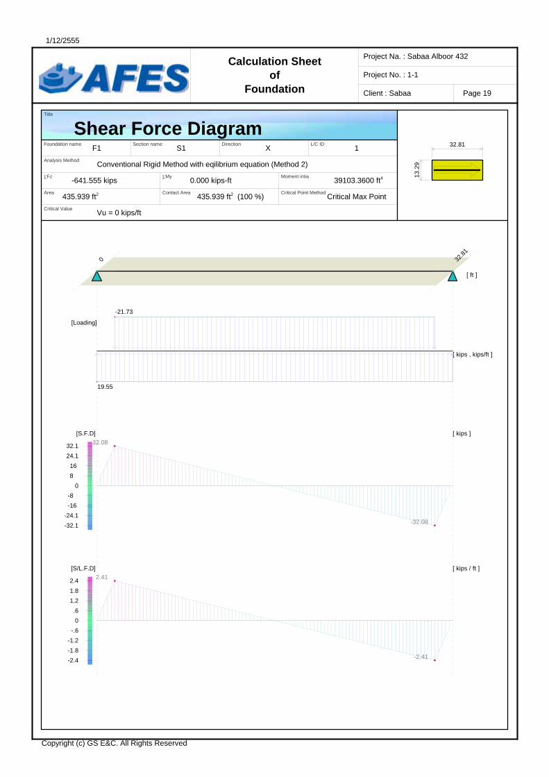
Page 19
Calculation Sheetof
Foundation
Project Na. : Sabaa Alboor 432
Project No. : 1-1
Client : Sabaa
32.81
13.2
9
Title
Foundation name Section name Direction L/C ID
Analysis Method
Fz My Moment intia
Area Contact Area Critical Point Method
Critical Value
Shear Force DiagramF1 S1 X 1
Conventional Rigid Method with eqilibrium equation (Method 2)
-641.555 kips 0.000 kips-ft 39103.3600 ft4
435.939 ft2 435.939 ft2 (100 %) Critical Max Point
Vu = 0 kips/ft
[ ft ]
0 32.8
1
[Loading]
[ kips , kips/ft ]
19.55
-21.73
[S.F.D] [ kips ]
32.1
24.1
16
8
0
-8
-16
-24.1
-32.1
32.08
-32.08
[S/L.F.D] [ kips / ft ]
2.4
1.8
1.2
.6
0
-.6
-1.2
-1.8
-2.4
2.41
-2.41
1/12/2555
Copyright (c) GS E&C. All Rights Reserved

Page 20
Calculation Sheetof
Foundation
Project Na. : Sabaa Alboor 432
Project No. : 1-1
Client : Sabaa
32.81
13.2
9
Title
Foundation name Section name Direction L/C ID
Analysis Method
Fz Mx Moment intia
Area Contact Area Critical Point Method
Critical Value
Shear Force DiagramF1 S1 Y 1
Conventional Rigid Method with eqilibrium equation (Method 2)
-641.555 kips 0.000 kips-ft 6413.9280 ft4
435.939 ft2 435.939 ft2 (100 %) Critical Max Point
Vu = -6.647 kips/ft
[ ft ]
0 8.77
13.2
9
[Loading]
[ kips , kips/ft ]48.28
-1564.37
[S.F.D] [ kips ]
310.9
233.2
155.5
77.7
0
-77.7
-155.5
-233.2
-310.9
218.02
310.84
-310.92
-218.08
[S/L.F.D] [ kips / ft ]
9.5
7.1
4.7
2.4
0
-2.4
-4.7
-7.1
-9.5
6.65
9.47
-9.48
-6.65
1/12/2555
Copyright (c) GS E&C. All Rights Reserved

Page 21
Calculation Sheetof
Foundation
Project Na. : Sabaa Alboor 432
Project No. : 1-1
Client : Sabaa
5.4 TWO WAY SHEAR FORCE 5.4.1 Two-Way Shear Formula
Vu = Fz Shade Ratio
(a) Vc1 = .8 2 (1 + 2/c) fck bo d (eq 11-33) <- Vc1
(b) Vc2 = .8 2 (1 + s d / 2 bo) fck bo d (eq 11-34) <- Vc2
(c) Vc3 = .8 4 fck bo d (eq 11-35) <- Vc3
Vc = Min( Vc1 , Vc2 , Vc3) ACI 318-05 CODE 11.12.2.1
Vu Vc , then OK
where
= ratio of long side to short side of the column, concentrated load or reaction area
s = 40 for interior colimns
= 30 for edge columns
= 20 for corner columns
bo = perimeter of critical section
Shade Ratio = Footing Area - Punching Area
Footing Area
5.4.2 Check of Two-WayShear
32.81
13.2
9
1
Ft.Name F1 Punching Area
Pr.Name 1 Ratio Shade
Shape Rectangle
L.Comb. 1
Pl 354.33 in
Pw 4.92 in
bo / d 810.79 / 23.07 in Vu
72 / 40 Result
1/12/2555
Copyright (c) GS E&C. All Rights Reserved
c / s
Vc1
Vc2
Vc3
Vc
10564.260 in2
.832
2009.332 kips
3067.626 kips
3910.051 kips
2009.332 kips
533.590 kips
OK

w/1
w/3, w/5, w/6
Detail of Wall Panel At :
Detail of Wall Panel At :
Side View & Not Scale
Detail At Position of Window
2-DB 12 mm.
varies
varies
varies
60 cm. 2-DB 12 mm. L = 1 m.
60 cm. 2-DB 12 mm. L = 1 m.
2-DB 16 mm.
0.80
m.
0.80
m.
1-DB 12 mm.
Header
Header
Wire Mesh (See Schedual of Wall Panel & Floor Plan)
Wire Mesh (See Schedual of Wall Panel & Floor Plan)

w/4
w/2
Detail of Wall Panel At :
Side View & Not Scale
Detail At Position of Window
Detail of Wall Panel At :
1-DB 12 mm. L = 2 m. 2-DB 10 mm. L = 30 cm.
1-DB 12 mm. L = 1.80 m.
2-DB 12 mm.
2-DB 16 mm.
DB 10 mm. @ 0.20 m. (L = 80∅)
varie
s 0.
80 m
.
1.80
m.
varies
Wire Mesh (See Schedual of Wall Panel & Flo Plan)
1-DB 12 mm.
Header
Wire Mesh (See Schedual of Wall Panel & Floor Plan)
DB 10 mm. @ 0.20 m. (L = 80∅)
Wire Mesh (See Schedual of Wall Panel & Floor Plan)

D/4
D/1, D2, D3, D5
Detail At Position of Door
Detail of Wall Panel At :
Detail of Wall Panel At :
Side View & Not Scale
F.F.L varies
1-DB 12 mm.
Header
2-DB 16 mm
2-DB 12 mm. L = 1 m.
Wire Mesh (See Schedual of Wall Panel & Floor Plan)
1-DB 12 mm.
Header
2-DB 12 mm.
2-DB 10 mm. L = 1 m.
Wire Mesh (See Schedual of Wall Panel & Floor Plan)
F.F.L varies

Detail At Joint of Wall Panel
Top View & Not Scale
Insid
e Fa
ce O
utsid
e Fa
ce
DB 10 mm. @ 0.20 m. (L = 100 cm.)
Wire Mesh (See Schedual of Wall Panel & Floor Plan)
DB 10 mm. @ 0.20 m. (L = 100 cm.)
Outside Face
Inside Face
Wire Mesh (See Schedual of Wall Panel & Floor Plan)
Insid
e Fa
ce
DB 10 mm. @ 0.20 m. (L = 100 cm.)
Wire Mesh (See Schedual of Wall Panel & Floor Plan)

Side View & Not Scale
Detail At Joint of Slab & Wall Panel
DB 10 mm. @ 0.20 m. (L = 100 cm.)
Wire Mesh (See Schedual of Wall Panel & Floor Plan)
Slab Reinf.(See Solid Slab Design List & Floor Plan)
Solid Slab W
all P
anel
Wal
l Pan
el
Top
Bottom
DB 10 mm. @ 0.20 m. (L = 100 cm.)
Solid Slab
Wal
l Pan
el
Wal
l Pan
el
Top
Bottom
Slab Reinf.(See Solid Slab Design List & Floor Plan)
2-DB 12 mm. L = 80∅ + Size of Opening
2-DB 12 mm. L = 80∅
Wal
l Pan
el
Solid Slab(S0)
Solid Slab(S3)
Slab Reinf.(See Solid Slab Design List & Floor Plan)
Solid Slab

Thickness
(cm.)
S0 16
S1 12
S2 12
S3 12
SerialUse Bottom As
Along Short Span
DB 10 mm. @ 0.20 m.
DB 10 mm. @ 0.20 m.
DB 10 mm. @ 0.20 m.
DB 10 mm. @ 0.20 m.
Use Top As
DB 10 mm. @ 0.20 m.
DB 10 mm. @ 0.20 m.
DB 10 mm. @ 0.20 m.
DB 10 mm. @ 0.20 m.
Tort. Reinr. At Exterior Corner Slab
Detail of Solid Slab & Beam
Side View & Not Scale
Solid Slab Design List
Along Long Span
BST: 12.50 x 45 cm.
oor
Short Span
Wal
l Pan
el
Solid Slab
Bottom As Top As
Bottom As Top As
DB 10 mm. @ 0.20 m. (L = 100 cm.)
Wal
l Pan
el
2-Stir. DB 8 mm. @ 0.20 m.
4-DB 12 mm.
4-DB 12 mm.
Short Span

Detail of Stair & Curtain Wall
Side View & Not Scale
Solid Slab(S0)
CT_WP 12.50 cm.
BST
BST
DB 12 mm. @ 0.10 m.
DB 10 mm. @ 0.15 m.
DB 10 mm. Each Steps
t = 0.17 m.
0.20
m.
0.30 m.
2-DB 12 mm. Anchorage = 40∅
Wire Mesh (CT_WP = WP1)
2-DB 12 mm. Anchorage = 40∅
Wire Mesh (CT_WP = WP1)

Side View & Not Scale
Detail of Raft Foundation
DB 10 mm. @ 0.20 m. (L = 100 cm.)
Wire Mesh (See Schedual of Wall Panel & Floor Plan)
Wall Panel
0.60
m.
Compacted Soil
100 mm. PCC 500 mm. Compacted Sub-Base
DB 16 mm. @ 0.25 m. Mesh (Top & Bott.)
DB 22 mm. @ 0.15 m. Mesh (Top & Bott.)
± 0.00

![Technical Notes 24C - The Contemporary Bearing Wall ... Notes 24C - The Contemporary Bearing Wall - Introduction to Shear Wall Design [Sept./Oct. 1970] (Reissued May 1988) INTRODUCTION](https://img.pdfslide.net/doc/110x75/5ae5c70a7f8b9acc268c74c3/technical-notes-24c-the-contemporary-bearing-wall-notes-24c-the-contemporary.jpg)