Embed Size (px)
Citation preview

022016| The Steel Network, Inc.www.steelnetwork.com | 1-888-474-4876Page | Load Bearing Wall Systems Construc� on Guide1
Load Bearing Wall Systems Construction Guide Introduc� on
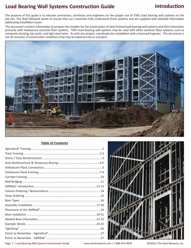
The purpose of this guide is to educate contractors, architects and engineers on the proper use of TSN’s load bearing wall systems on the job site. The Steel Network wants to ensure that our customers fully understand these systems and are supplied with detailed informa� on addressing installa� on issues.
This document contains informa� on to prepare the installer for the construc� on of steel framed load bearing wall systems and their interac� on primarily with Hollowcore concrete � oor systems. TSN’s load bearing wall systems may be used with other common � oor systems, such as composite decking, bar joists, and light steel joists. As with any project, coordinate the installa� on with a licensed Engineer. This document is not all-inclusive of construc� on condi� ons that may be experienced on a project.
Table of Contents
SigmaStud® Framing...........................................................................................2
Track Framing ................................................................................................2-3
Shims / Track Reinforcement ............................................................................3
Hole Reinforcement & Temporary Bracing ....................................................4-5
Hollowcore Plank Connections .........................................................................6
Hollowcore Plank Framing .............................................................................7-9
Corridor Framing .............................................................................................10
Wall Bridging ...................................................................................................11
S� � Wall® Introduction................................................................................12-13
Column Ordering / Nomenclature...................................................................14
Strap Ordering ................................................................................................15
Boot Types ......................................................................................................16
Assembly Installation ................................................................................17-18
Placement of the StiffWall® ............................................................................19
Boot Installation ........................................................................................20-21
Welded Boot Information...........................................................................22-23
Example Details .........................................................................................24-25
TightStrap® ......................................................................................................26
Points to Remember - SigmaStud® ..................................................................27
Points to Remember - S� � Wall® .....................................................................27

The Steel Network, Inc. | 022016 www.steelnetwork.com | 1-888-474-4876 Load Bearing Wall Members Construc� on Guide | Page 2
Load Bearing Wall Systems Construction Guide SigmaStud® Framing
SigmaStud®
SigmaStud® installa� on is similar to that of standard “cee” studs. There are some key details that the contractor needs to be familiar with in order to ensure that these load-bearing studs are installed according to manufacturer recommenda� ons.
Installing SigmaStud to Track
SigmaStud � ts into standard sized SSMA (T) Sec� on Track members. Typically, one screw is used on each side of the stud to a� ach the stud to
the track. As with SSMA stud sec� on framing, low pro� le screws are recommended in order to reduce any bulging or “bump-out” where the
� nishing material covers the screws.
• Each stud is cut to the speci� ed length (each length must be speci� ed at � me of order)
• Standard punchouts begin no less than 10” from the end, with spacing every 24” therea� er
• Punchout spacing can be customized to project-speci� c requests
• Orders can be bundled per � oor or for speci� c customer requests
• TSN manufactures SSMA (T) Sec� on Tracks (all standard depths and thickness)
• Available in 10’ standard lengths
• Custom lengths are available
Nomenclature
SigmaStud® is designated with the same standardized nomenclature set forth by the Steel Stud Manufacturers Associa� on (SSMA):
Track Recommenda� ons
• The top and bo� om track should match the stud thickness
• Minimum track thickness = 54mils
• When welding is required to the top track, it is recommended to use a 14ga (68mil) thickness. Welding may be used as a means of a� aching light gauge components, and should be performed by an AWS cer� � ed welder.

022016| The Steel Network, Inc.www.steelnetwork.com | 1-888-474-4876Page | Load Bearing Wall Systems Construc� on Guide3
Load Bearing Wall Systems Construction Guide
Shims
If shims are used to correct situa� ons where gaps exist between the stud and the track:
• The gap between the track and the plank at load bearing stud loca� ons must not exceed �”.
• If the gap exceeds �”, shim or grout this area with structural non-shrink grout – 4,000 psi minimum.
• Grout should be applied so it covers an area equivalent to twice the width of the stud.
• Coordinate this procedure with the plank manufacturer/ installer or the general contractor.
• Place the order for shims at the same � me as the SigmaStud order.
SigmaTrak®TSN’s SigmaTrak allows studs to seat fully within the track, providing full bearing at the top and bo� om structural tracks. Visit www.steelnetwork.com for more informa� on
Track Splicing/Reinforcement
The top and bo� om wall tracks in contact with the planks need to be con� nuous. The contractor must provide track splicing if the tracks are cut.
• To splice track in a load-bearing wall, an extra piece of stud must be used inside the track to su ciently overlap each side of the joint. 2-3 screws are then installed through the � anges on each side of the joint, on both sides of the track (for a total of 8-12 screws per splice).
• In adjacent walls ending with edge studs, a plate may be screwed or welded across the � anges of the end studs of two adjacent walls. In addi� on to this, the studs must be screwed or welded together per standard column/screw guidelines.
Load bearing studs must be fully seated within the top and bo� om track. Design standards recommend a maximum gap of �” in order to obtain an e� ec� ve bearing condi� on.
Max. �”
SigmaStud® Framing

The Steel Network, Inc. | 022016 www.steelnetwork.com | 1-888-474-4876 Load Bearing Wall Members Construc� on Guide | Page 4
Load Bearing Wall Systems Construction Guide
Temporary Construc� on Bracing
Temporary construc� on bracing is necessary in order to install steel framed load bearing wall systems. Coordinate temporary bracing with the Specialty Engineer and/or the General Contractor. Safe and proper installa� on and “loading” of the walls can only be achieved if the adequate temporary bracing is installed. Failure to do this can result in wall failure and/or the risk of serious injury. Two types of construc� on bracing are required:
• In the plane of the wall (may employ the X-bracing of the shear wall panels and/or by adding diagonal kickers at the two ends of the wall).
• Out of the plane of the wall.
PLAN VIEW SIDE VIEW
Suggested Minimum Construc� on Bracing for Load Bearing Wall 10’ or Less, Out-of-Plane
Reinforcing Non-Standard Holes in SigmaStud®
Each SigmaStud contains punchouts which are 1.5” wide and 4” tall, spaced every 24” o.c. ver� cally. Any larger holes cut into SigmaStud require a review by the engineer, as load capacity is based on the existence of standard punchouts. With the realiza� on that addi� onal holes do manage to appear in studs, TSN provides the following recommenda� ons:
When should temporary construc� on bracing be removed?• A� er at least 2 � oors above the temporarily braced wall are installed, allowing the walls to “seat”.
• A� er all permanent shear wall bracing is installed and � ghtened.
• A� er all of the perpendicular walls are connected.
Temporary bracing should be designed by a design professional.
SigmaStud® Framing
• Reinforce any holes added during the project construc� on.
• Review the detail at right for a possible solu� on recommended by TSN (all modi� ca� ons to SigmaStud must be reviewed by a structural engineer).
• For 33-54mil SigmaStud, use 54mil RFT. For 68mil and higher, use 97mil RFT.
• Contact TSN’s Project Management Team at (888) 474-4876 for more recommenda� ons.
022016| The Steel Network, Inc.www.steelnetwork.com | 1-888-474-4876Page | Load Bearing Wall Systems Construc� on Guide5
Load Bearing Wall Systems Construction Guide
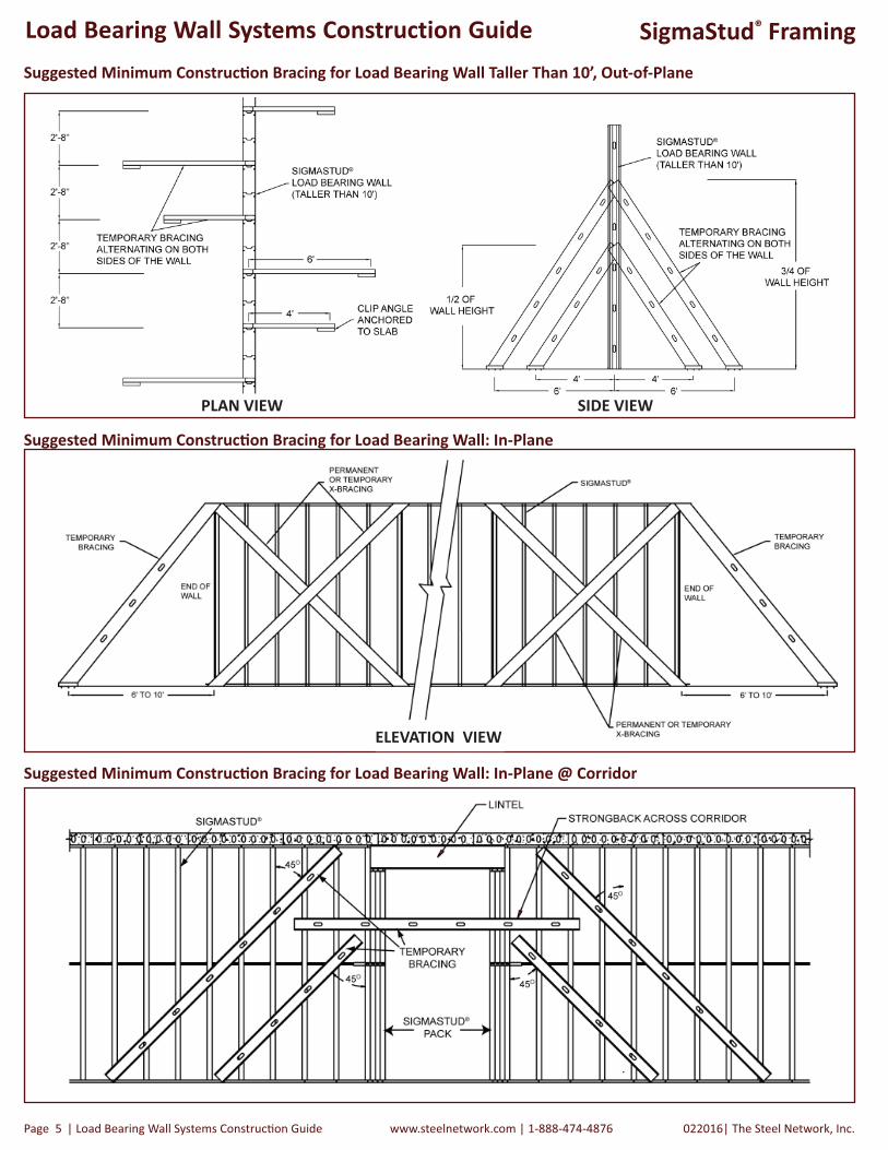
Suggested Minimum Construc� on Bracing for Load Bearing Wall Taller Than 10’, Out-of-Plane
Suggested Minimum Construc� on Bracing for Load Bearing Wall: In-Plane
Suggested Minimum Construc� on Bracing for Load Bearing Wall: In-Plane @ Corridor
ELEVATION VIEW
SigmaStud® Framing
PLAN VIEW SIDE VIEW

The Steel Network, Inc. | 022016 www.steelnetwork.com | 1-888-474-4876 Load Bearing Wall Members Construc� on Guide | Page 6
Load Bearing Wall Systems Construction Guide
Corridor Framing
In applica� ons where the plank spans bays that are parallel to the corridor, plank direc� on can be maintained in the corridor through the use of a load distribu� on lintel. Structural steel is commonly used to act as the lintel to support the opening, resul� ng in increased point loads ac� ng on the columns. Bearing requirements for various types of structural steel vary and must be sa� s� ed.
• Typically, mul� ple studs of the same thickness are used in “stud-packs” to provide bearing points for structural steel lintels.
• Coordinate the use of “stud packs” with the structural engineer.
Hollow Core Plank Connec� ons
If the � oor system consists of hollow core planks:
• Typically a� ach the top track to the � oor above by welding the bo� om of a key plate (Splice Plate) to the track.
• The key is then grouted in between the two planks, connec� ng the � oor system to the rest of the structure.
• Embedded bolts/anchors and power-actuated fasteners can also serve to connect the load bearing walls with various � oorddiaphragms, per the structural engineer’s speci� ca� ons.
• Be sure to clarify speci� c methods of a� achment with the engineer.
Key Plate Detail
SigmaStud® Framing

022016| The Steel Network, Inc.www.steelnetwork.com | 1-888-474-4876Page | Load Bearing Wall Systems Construc� on Guide7
Load Bearing Wall Systems Construction Guide
Uneven Plank
Having a solid, level surface is cri� cal for load bearing metal framing. Typical plank tolerances are up to ± ¼”. This tolerance between planks can cause metal framing to not be level across the planks.
The tolerance from the plank is more cri� cal with load bearing stud systems vs. other structural systems. Each � oor level is built o� of the � oor and studs below, so a building can increase or decrease in height across the same � oor due to the plank tolerance. In other structural systems, the height can be controlled within the system, i.e. within the mortar.
The responsibility of providing the level surface is a gray area. Project success requires that the framing start from each � oor from a level surface. Proper coordina� on between the design team, general contractor, plank erector and light steel framer is required to ensure the building is built level and that each story is of the proper dimension. The scenarios on the following pages refer to the “Plank Direc� on - Interior & Exterior Walls - Plan View” drawing below.
Plank Direc� on - Interior & Exterior Walls, Plan View
SigmaStud® Framingw/ HC Plank

The Steel Network, Inc. | 022016 www.steelnetwork.com | 1-888-474-4876 Load Bearing Wall Members Construc� on Guide | Page 8
Load Bearing Wall Systems Construction Guide
Scenario One is a wall applica� on where two planks meet end to end, each bearing on a single stud. An uneven gap exists between the planks, and one of the planks is slightly lower than the adjacent plank. The grouted area is not only between the planks but also across the top surface of the planks where the next � oor framing will intersect the planks as shown. A typical grout width is 16” for this scenario. Be sure to require a trowled � nish.
Scenario One: Load Bearing Wall - Uneven Planks Parallel To The Wall Frame
Studs and track within load bearing walls must have full bearing (level) to the � oor diaphragm at the bo� om and the top of the wall.
Uneven hollow core plank as a result of various thicknesses therefore requires a� en� on.
Grout across planks where load bearing walls exist & not just between planks at every � oor, to ensure a level framing surface.
SigmaStud® Framingw/ HC Plank
022016| The Steel Network, Inc.www.steelnetwork.com | 1-888-474-4876Page | Load Bearing Wall Systems Construc� on Guide9
Load Bearing Wall Systems Construction Guide
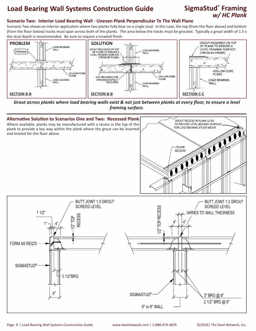
Scenario Two: Interior Load Bearing Wall - Uneven Plank Perpendicular To The Wall PlaneScenario Two shows an interior applica� on where two planks fully bear on a single stud. In this case, the top (from the � oor above) and bo� om
(from the � oor below) tracks must span across both of the planks. The area below the tracks must be grouted. Typically a grout width of 1.5 x
the stud depth is recommended. Be sure to require a trowled � nish.
SOLUTIONPROBLEM
SECTION B-B SECTION B-B
Grout across planks where load bearing walls exist & not just between planks at every � oor, to ensure a level framing surface.
SECTION C-C
Where available, planks may be manufactured with a recess in the top of the plank to provide a key way within the plank where the grout can be inserted and leveled for the � oor above.
Alterna� ve Solu� on to Scenarios One and Two: Recessed Plank
SigmaStud® Framingw/ HC Plank

The Steel Network, Inc. | 022016 www.steelnetwork.com | 1-888-474-4876 Load Bearing Wall Members Construc� on Guide | Page 10
Load Bearing Wall Systems Construction Guide
Panelized Walls
When li� ing wall panels into place, avoid using
the bridging as a li� point. This could bend the
bridging members, rendering them ine� ec� ve.
Here are two sugges� ons that have worked well
in exis� ng installa� ons:• A� ach a temporary stud or other bracing
member (“strong back”) horizontally across the wall panel and use it to li� the
wall sec� ons into place.
• Thread the cables through the stud punchouts at either end to li� the panel.
Strong Back Threaded Cable
SigmaStuds connected together with weld (at le� ) or � at plate
(at right).
Framing Examples
Load Distribu� on Lintel (Structural
steel)
Sigmastud “packs” to support
lintel above
Bridging method
anchored to column
Floor plan indica� ng direc� on of plank and callout example of corridor framing.
Built-up corridor framing with bridging anchorage.
Picture of corridor framing, with SigmaStuds suppor� ng the distribu� on
lintel.

022016| The Steel Network, Inc.www.steelnetwork.com | 1-888-474-4876Page | Load Bearing Wall Systems Construc� on Guide11
Load Bearing Wall Systems Construction Guide Wall Bridging
Load Bearing Wall Bridging Row Anchored to a Jamb or End Column - Track Bracing U� lizing BuckleBridge®
Key Bridging Issues:
• What is the bridging method?
• How many rows of bridging exist on each wall?
• If there is more than one row of bridging per wall – what is the ver� cal distance (spacing) between the bridging rows?
• What is the bridging anchorage method?
• What is the spacing for bridging anchorage?
Load Bearing Wall Bridging Row Anchored to Floor System Through Cross-Bracing U� lizing BridgeBar® 150
with BC600/BC800
BuckleBridge® BridgeBar® with BC600/800 Flat Strap Bridging
Wall Bridging Methods:
• Spaces studs at 16” o.c.
• Typically used in higher-load applica� ons.
• Notches every 4” accommodate stud spacings.
• Fast attachments with TSN’s bridging clips.
• Straps are installed on both sides of the wall.
• Solid blocking as required.
X-Bracing consists of the designed
strap connec� ng the bridging
method with the top or bo� om
runner track.
Field fabricated
track screw
a� ached to
BuckleBridge® &
column.
Load Bearing Wall Bridging Row Anchored to a Jamb or End Column - Flat Strap Bridging
Solid blocking (as
required)
Gusset plate a� ached
with screws in each
� ange and strap
Load Bearing Wall Bridging Anchorage Methods
BackgroundBridging is a cri� cal element of a properly constructed load bearing wall system and is designed to resist horizontal and/or lateral loads developing in the wall system. As axial (ver� cal) load is applied to a wall stud, it will react by buckling and twis� ng about its weak axis. Wall bridging methods resist this tendency to buckle. The loads will accumulate in the wall through the bridging method, and need to be transferred to the structure via a bridging anchorage point. Some anchorage examples are shown below. Consult your structural engineer for the full bridging design. TSN’s Engineering Team is available to make recommenda� ons for speci� c project condi� ons.

The Steel Network, Inc. | 022016 www.steelnetwork.com | 1-888-474-4876 Load Bearing Wall Members Construc� on Guide | Page 12
Load Bearing Wall Systems Construction Guide S� � Wall® Introduc� on
S� � Wall® is a simpli� ed shear wall system consis� ng of two Column/Boot assemblies (one at each end post) and Flat Strap (each side of X-bracing). The S� � Wall is embedded into the load bearing and non-load bearing walls. Perform your stud take o� as normal, then order the Column/Boot Assembly and the Flat Strap as separate items. Each Column is delivered fully assembled with boots a� ached and ready for installa� on to the wall panels per project requirements.
TSN’s S� � Wall allows for an e cient veri� ca� on of load paths through a structure. S� � Wall is usually not designed as a gravity load bearing element. However, its boundary end columns can see compression loads from the � oor weight above. For the purpose of this document it will be assumed that all S� � Wall elements are non-gravity-load-bearing.
* S� � Wall® is embedded between studs and does not replace in� ll studs, as they act independantly of the shear wall.
** The � oor slabs are part of the lateral load resis� ng system, but are not part of TSN’s S� � Wall system.
*** Anchor bolts are not included with Column/Boot Assembly. 1¼” anchor is required for LG and TR boots, & ” is required for ME, SM, PL and LT boots.
S� � Wall® Components
Column/Boot Assembly(1) at each end post
(same height as studs)
SigmaStud® & BuckleBridge®
Load bearing wall studs & bridgingare not a part of the S� � Wall System*
Flat Strap(2) at each side of X-bracing
S� � Wall® SystemEmbedded within load
bearing wall studs
S� � Wall® Column Boot Assembly (C/STW)• End posts for the shear wall - Columns come pre-assembled with
boots & strap track for easy installa� on into the wall
• Wider � ange & addi� onal return lips provide an increased load capacity over standard steel studs
Flat Strap (FS)
• X-braced straps arrive at the jobsite cut to length elimina� ng splicing
• Runs diagonally as a single piece and a� aches to the strap track on each side of the wall
• Made to your speci� ca� ons, always using 50 ksi steel
SigmaStud® (SG)
• Can be used as in� ll studs in loadbearing applica� ons to reduce material & � me required installing � nishes
• S� � Wall is embedded between studs and does not replace load bearing studs
TightStrap® Tension Tool
• Device used to � ghten � at strap in the � eld, removing “waviness” or “bowing” prior to fastening
• Ensures op� mal system perfomance

022016| The Steel Network, Inc.www.steelnetwork.com | 1-888-474-4876Page | Load Bearing Wall Systems Construc� on Guide13
Load Bearing Wall Systems Construction Guide S� � Wall® Components
Columns
The S� � Wall® Columns (C/STW) are the end posts for the shear wall. The unique Columns contain a wider � ange and addi� onal return lips to provide an increased load capacity over regular steel stud sec� ons. The Column web is narrower than a standard (S) sec� on to allow for the placement of the � at straps within the Strap Track, which then � ts into a standard (T) Sec� on track. Because of this, the (S) sec� on can not be used with the S� � Wall
® Boot.
Boots
S� � Wall® Boots are designed to e ciently transfer the loads from the straps and columns through the � oor system down to the founda� on. Through-� oor bolts are not provided with the S� � Wall.
• The S� � Wall Boot is made up of a Strap Track and a Base Plate (“T” shaped structural steel), speci� ed bolts for connec� on to Column, and is designed to � t into a standard size track.
• The Strap Track is a piece of track 12” long with pre-punched screw pilot holes. The purpose of the Strap Track is to a� ach the strap to the Boot assembly.
• The Boots are designed to match the Column width and are designated Light-Large (Refer to S� � Wall Boot Dimensions for more informa� on).
• S� � Wall Boots are pre-installed to the top and bo� om of each Column. The a� achment to the Column is made via the required number of A325 bolts.
• Each Column is shipped with the appropriate Boot a� ached at the top and bo� om.
Example:
600S250-68 Stud Depth is exactly 6”
600C/STW250-68 Column Depth is 5.639”
Flat Strap• Runs diagonally (corner to corner) as a single piece and a� aches to the strap track in an “X” pa� ern
• Flat Strap is to be installed on both sides of the S� � Wall shear wall, and is not to be spliced unless approved by the design engineer.
• Flat Strap is available in a variety of widths and is always manufactured from 50 ksi steel.
• Four (4) pieces of � at strap are used in each S� � Wall.
Small Boot Medium Boot Transition Boot Large BootLight Boot Plus Boot

The Steel Network, Inc. | 022016 www.steelnetwork.com | 1-888-474-4876 Load Bearing Wall Members Construc� on Guide | Page 14
Load Bearing Wall Systems Construction Guide Ordering S� � Wall®
Ordering Informa� on
TSN’s S� � Wall shear wall system consists of two Column assemblies (at each end post) and Flat Strap (2 sides of X-bracing). The S� � Wall � ts into or is embedded into the load bearing and non-load bearing walls (refer to Placement of the S� � Wall® Column and Boot system in a load bearing wall). Do your stud take o� as normal and order the Column/Boot Assembly and the Flat Strap as separate items. This page will take you through the process of ordering the Column/Boot Assembly, and the next page will address the Flat Strap.
Columns
Each S� � Wall Column is delivered to the job site with the Boots pre-installed at the top and bo� om. The added value of the pre-installed boots minimizes tolerance issues during erec� on. Simply specify the clear span of the bearing wall system and TSN will ship the Column/Boot assembly to meet the given wall height
at a tolerance of +0/-�”.
Nomenclature

022016| The Steel Network, Inc.www.steelnetwork.com | 1-888-474-4876Page | Load Bearing Wall Systems Construc� on Guide15
Load Bearing Wall Systems Construction Guide
Flat Strap
Flat Strap is cut to length with square ends, and will need to be cut to � nal length in the � eld. To determine the length of the � at straps, follow these simple steps:
1. Find the width (A) and the height (B) of the S� � Wall.
2. Then, use the following formula to determine the length of the strap: A2 + B2 = C2
3. Next, take the square root of C, round up to the nearest whole number and add 1.
• Strap must be pulled � ght a� er a gravity load above has been applied. TightStrap® tool can be used to � a� en the strap and put minor tension force into it.
• Flat strap cannot be installed, then un-installed by releasing the screws to the strap track, and then re-installed with screws again in the same screw holes. Either a new piece of strapis required, or the exposed edge of the strap needs to be welded to the strap track with an approved weld design.
• It is recommended not to fasten the strap to the in� ll studs between the columns. However, typical or occasional a� achment of sheathing and/or resilient channel to the in� ll studs through the strap is acceptable.
• Straps should not be spliced without an approved design.
• Four (4) pieces of strap are required in each S� � Wall (If there are 10 S� � Wall shear walls, 40 pieces of � at strap will be necessary).
This will result in a length in feet that you can work with. If C equals a whole number, you may want to add 2 to make sure the length is enough.
Example: 8’ wall height with a width of 16’ would look like this:
(8x8) + (16x16) = 320. �320 = 17.88
Then round up to 18’ and add 1’ for a strap length of 19’.
Some points to remember concerning Flat Strap:
Ordering S� � Wall®
Available Sec� ons for S� � Wall®
Subs� tu� ng TSN Flat Strap with 33ksi material will alter the performance and allowable loads of the S� � Wall®, and is not recommended.
• FS400-54, 50ksi 4” Flat Strap 54 Mil (16ga), 50ksi Strap
• FS600-54, 50ksi 6” Flat Strap 54 Mil (16ga), 50ksi Strap
• FS800-54, 50ksi 8” Flat Strap 54 Mil (16ga), 50ksi Strap
• FS800-68, 50ksi 8” Flat Strap 68 Mil (14ga), 50ksi Strap
• FS1000-68, 50ksi 10” Flat Strap 68 Mil (14ga), 50ksi Strap
Nomenclature
l l h f
Use TightStrap® for a quick and proven method to field tighten flat straps.
The Steel Network, Inc. | 022016 www.steelnetwork.com | 1-888-474-4876 Load Bearing Wall Members Construc� on Guide | Page 16
Load Bearing Wall Systems Construction Guide S� � Wall® Boots
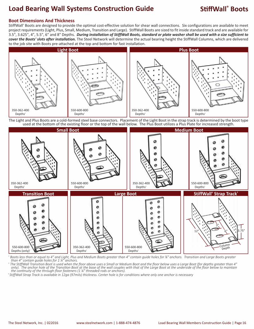
The Light and Plus Boots are a cold-formed steel base connectors. Placement of the Light Boot in the strap track is determined by the boot type used at the bottom of the existing floor or the top of the wall below. The Plus Boot utilizes a Plus Plate for increased strength.
350-362-400
Depths1
350-362-400
Depths1
550-600-800
Depths1
550-600-800
Depths1
Light Boot Plus Boot
Small Boot
StiffWall® Strap Track3
Boot Dimensions And ThicknessStiffWall® Boots are designed to provide the optimal cost-effective solution for shear wall connections. Six configurations are available to meet project requirements (Light, Plus, Small, Medium, Transition and Large). StiffWall Boots are sized to fit inside standard track and are available for 3.5", 3.625", 4", 5.5", 6" and 8" Depths. During installation of StiffWall Boots, standard or plate washer shall be used with a size sufficient to cover the Boots' slots after installation. The Steel Network will determine the actual bearing height the StiffWall Columns, which are delivered to the job site with Boots pre-attached at the top and bottom for fast installation.
12"
Column
Depth
3.75"
Medium Boot
Transition Boot
350-362-400
Depths1
550-600-800
Depths1
350-362-400
Depths1
550-600-800
Depths1
550-600-800
Depths (only)2
Large Boot
350-362-400
Depths1
550-600-800
Depths1
2 ������������ ���������������������������������� ��������������������� ������������������������ ���������������� ���������� ��������� ���� ���������������� !��������"�� ������������� ����#��������������������������������"������������������������� ������������������� �����������$��� ��������������������������"��#��������������� ����%$��� ������� ���&�'���� ������ ����� ���"�� � !�
1 ����������������� ��(�������������������)�*���������������������� ���� ���������"�������������������� �+����"�� �!��� ��������������� ���������� ���� ������������"�������������������� �&�'����"�� �!
6"
3"
3 ��������� ���� �",�����������������&-����./���� ����",����!�0���� ���������� �"������������� �������������"�� ������"���� �

022016| The Steel Network, Inc.www.steelnetwork.com | 1-888-474-4876Page | Load Bearing Wall Systems Construc� on Guide17
Load Bearing Wall Systems Construction Guide S� � Wall® Installa� on
How to install the S� � Wall® Shear Wall
S� � Wall is usually not designed as a gravity load bearing element. However, its boundary end columns can see compression loads from the � oor weight above. This system is designed to sit in between load bearing studs and address all of the lateral loads ac� ng on that building due to wind or earthquakes.
The S� � Wall is designed to stack ver� cally and a� ach through the � oor system to the level above. The Columns for one � oor must line up with the columns on the � oors above and below. This will allow for the bolts from one � oor to be bolted through the � oor system to the boots above and/or below. It is important that these bolts are properly aligned through each � oor for the walls to be able to work together as one unit from top to bo� om. Do not enlarge the anchor holes in the S� � Wall
® Boots.
Pre-punched holes in the Boot
The S� � Wall® Column Assembly � ts inside the Strap Track. A� ach the S� � Wall
Column and the anchor to the founda� on through holes on either side of the
Column.
S� � Wall® Strap Track
Do not enlarge the anchor holes in the Boot.
A� ach the track to the � at strap with required screws through prepunched
holes in the Strap Track. Standard 1 ¼” leg runner track
The Steel Network, Inc. | 022016 www.steelnetwork.com | 1-888-474-4876 Load Bearing Wall Members Construc� on Guide | Page 18
Load Bearing Wall Systems Construction Guide
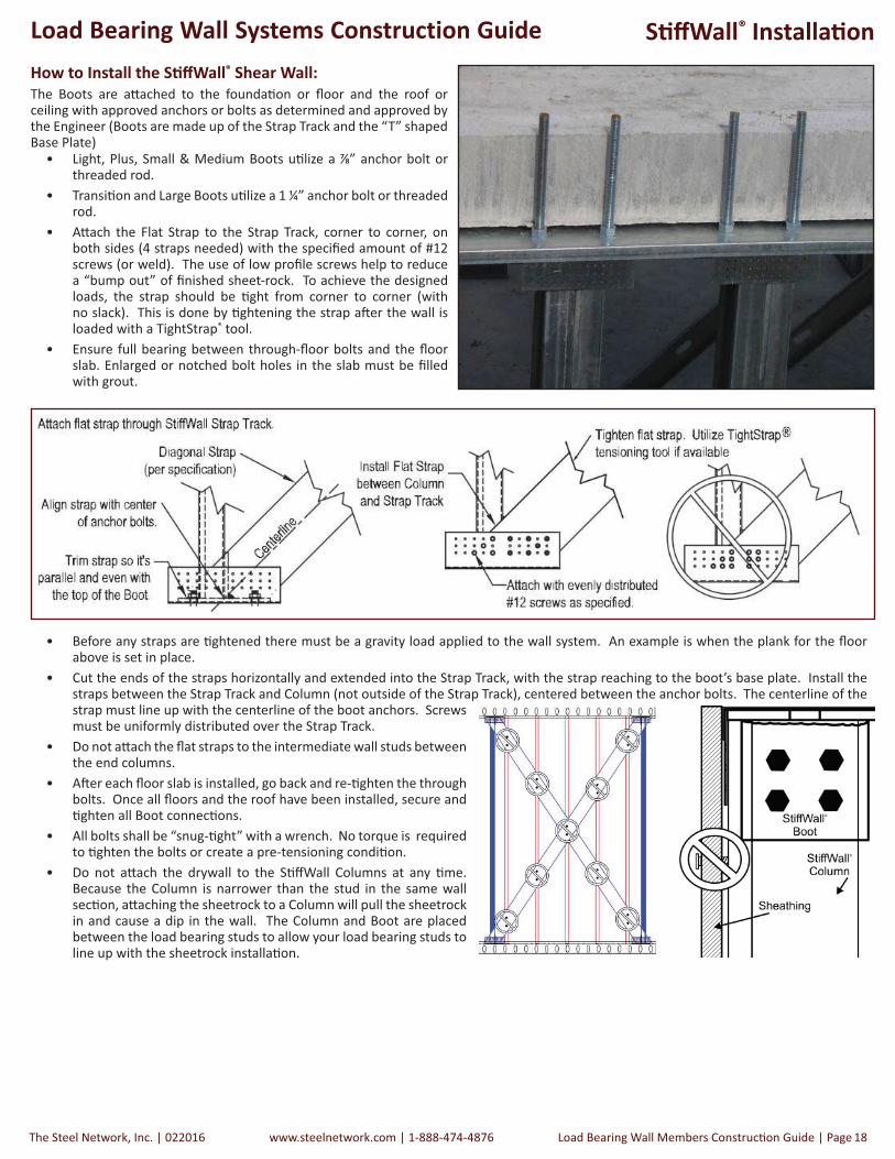
• Before any straps are � ghtened there must be a gravity load applied to the wall system. An example is when the plank for the � oor above is set in place.
• Cut the ends of the straps horizontally and extended into the Strap Track, with the strap reaching to the boot’s base plate. Install the straps between the Strap Track and Column (not outside of the Strap Track), centered between the anchor bolts. The centerline of the strap must line up with the centerline of the boot anchors. Screws must be uniformly distributed over the Strap Track.
• Do not a� ach the � at straps to the intermediate wall studs between the end columns.
• A� er each � oor slab is installed, go back and re-� ghten the through bolts. Once all � oors and the roof have been installed, secure and � ghten all Boot connec� ons.
• All bolts shall be “snug-� ght” with a wrench. No torque is required to � ghten the bolts or create a pre-tensioning condi� on.
• Do not a� ach the drywall to the S� � Wall Columns at any � me. Because the Column is narrower than the stud in the same wall sec� on, a� aching the sheetrock to a Column will pull the sheetrock in and cause a dip in the wall. The Column and Boot are placed between the load bearing studs to allow your load bearing studs to line up with the sheetrock installa� on.
How to Install the S� � Wall® Shear Wall:
The Boots are a� ached to the founda� on or � oor and the roof or ceiling with approved anchors or bolts as determined and approved by the Engineer (Boots are made up of the Strap Track and the “T” shaped Base Plate)
• Light, Plus, Small & Medium Boots u� lize a ” anchor bolt or threaded rod.
• Transi� on and Large Boots u� lize a 1 ¼” anchor bolt or threaded rod.
• A� ach the Flat Strap to the Strap Track, corner to corner, on both sides (4 straps needed) with the speci� ed amount of #12 screws (or weld). The use of low pro� le screws help to reduce a “bump out” of � nished sheet-rock. To achieve the designed loads, the strap should be � ght from corner to corner (with no slack). This is done by � ghtening the strap a� er the wall is loaded with a TightStrap® tool.
• Ensure full bearing between through-� oor bolts and the � oor slab. Enlarged or notched bolt holes in the slab must be � lled with grout.
S� � Wall® Installa� on

022016| The Steel Network, Inc.www.steelnetwork.com | 1-888-474-4876Page | Load Bearing Wall Systems Construc� on Guide19
Load Bearing Wall Systems Construction Guide S� � Wall® Placement
Floor System
SigmaStud®
S� � Wall® Boot
S� � Wall® Column
Placement of the S� � Wall® Column and Boot system in a load bearing wall.
16” 16” 16” 16” 16” 16” 16” 16”
The S� � Wall Columns are designed to sit in between load bearing studs and address all of the lateral loads ac� ng on that building due to wind or earthquakes. The illustra� on below is an example representa� on of the Column placement. Common stud spacing is either 16” or 24” on center.

The Steel Network, Inc. | 022016 www.steelnetwork.com | 1-888-474-4876 Load Bearing Wall Members Construc� on Guide | Page 20
Load Bearing Wall Systems Construction Guide S� � Wall® Column Installa� on
1. Posi� on bo� om track on slab and provide holes in track web for anchor bolts.
2. Nest a S� � Wall Column assembly into the track over the anchors. Install washers and � ghten nuts per manufacturer’s recommenda� ons.
3. Install required in� ll studs un� l the next S� � Wall Column is encountered. Install S� � Wall Column assembly as shown in step 2.
4. Install top track. Track web holes must be provided at boot assembly loca� ons for upper � oor anchors to pass through.
5. Install anchors or through rods into the top base plates. If another � oor is to be added, and through rods are used, they will extend through the � oor and into the lower S� � Wall boot assembly of the next � oor. 6. Install Flat Strap X-Bracing.
The Steel Network, Inc. | 022016 www.steelnetwork.com | 1-888-474-4876 Load Bearing Wall Members Construc� on Guide | Page 22
Load Bearing Wall Systems Construction Guide
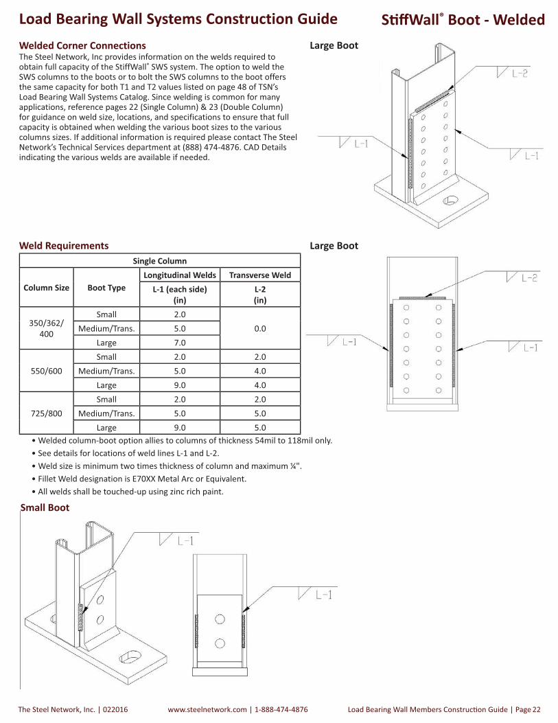
Weld Requirements
• Welded column-boot option allies to columns of thickness 54mil to 118mil only.
• See details for locations of weld lines L-1 and L-2.
• Weld size is minimum two times thickness of column and maximum ¼".
• Fillet Weld designation is E70XX Metal Arc or Equivalent.
• All welds shall be touched-up using zinc rich paint.
Single Column
Column Size Boot Type
Longitudinal Welds Transverse Weld
L-1 (each side)
(in)
L-2
(in)
350/362/
400
Small 2.0
0.0Medium/Trans. 5.0
Large 7.0
550/600
Small 2.0 2.0
Medium/Trans. 5.0 4.0
Large 9.0 4.0
725/800
Small 2.0 2.0
Medium/Trans. 5.0 5.0
Large 9.0 5.0
Welded Corner ConnectionsThe Steel Network, Inc provides information on the welds required to obtain full capacity of the StiffWall® SWS system. The option to weld the SWS columns to the boots or to bolt the SWS columns to the boot offers the same capacity for both T1 and T2 values listed on page 48 of TSN’s Load Bearing Wall Systems Catalog. Since welding is common for many applications, reference pages 22 (Single Column) & 23 (Double Column) for guidance on weld size, locations, and specifications to ensure that full capacity is obtained when welding the various boot sizes to the various columns sizes. If additional information is required please contact The Steel Network’s Technical Services department at (888) 474-4876. CAD Details indicating the various welds are available if needed.
Large Boot
Large Boot
Small Boot
S� � Wall® Boot - Welded

022016| The Steel Network, Inc.www.steelnetwork.com | 1-888-474-4876Page | Load Bearing Wall Systems Construc� on Guide23
Load Bearing Wall Systems Construction Guide
Weld Requirements
• Welded column-boot option allies to columns of thickness 54mil to 118mil only.
• See details for locations of weld lines L-1 and L-2.
• Weld size is minimum two times thickness of column and maximum ¼".
• Fillet Weld designation is E70XX Metal Arc or Equivalent.
• All welds shall be touched-up using zinc rich paint.
Double Column
Column Size Boot TypeTransverse Weld
Top L-2 (in.) Bottom L-3 (each side) (in.) Bottom L-4 (in.) # of Inside ½" Holes
350/362/ 400
Small 2.0
0.0
2.00
Medium/Trans. 2.5 4.0
Large 2.5 4.0 5
550/600
Small 4.00.0
4.00
Medium/Trans. 4.5 5.5
Large 4.5 1.0 6.5 8
725/800
Small 2.00.0
4.00
Medium/Trans. 5.0 7.0
Large 9.0 1.0 7.0 8
Large Boot Large Boot
Large Boot Large Boot Small Boot
Small Boot
S� � Wall® Boot - Welded
The Steel Network, Inc. | 022016 www.steelnetwork.com | 1-888-474-4876 Load Bearing Wall Members Construc� on Guide | Page 24
Load Bearing Wall Systems Construction Guide S� � Wall® Connec� on Details
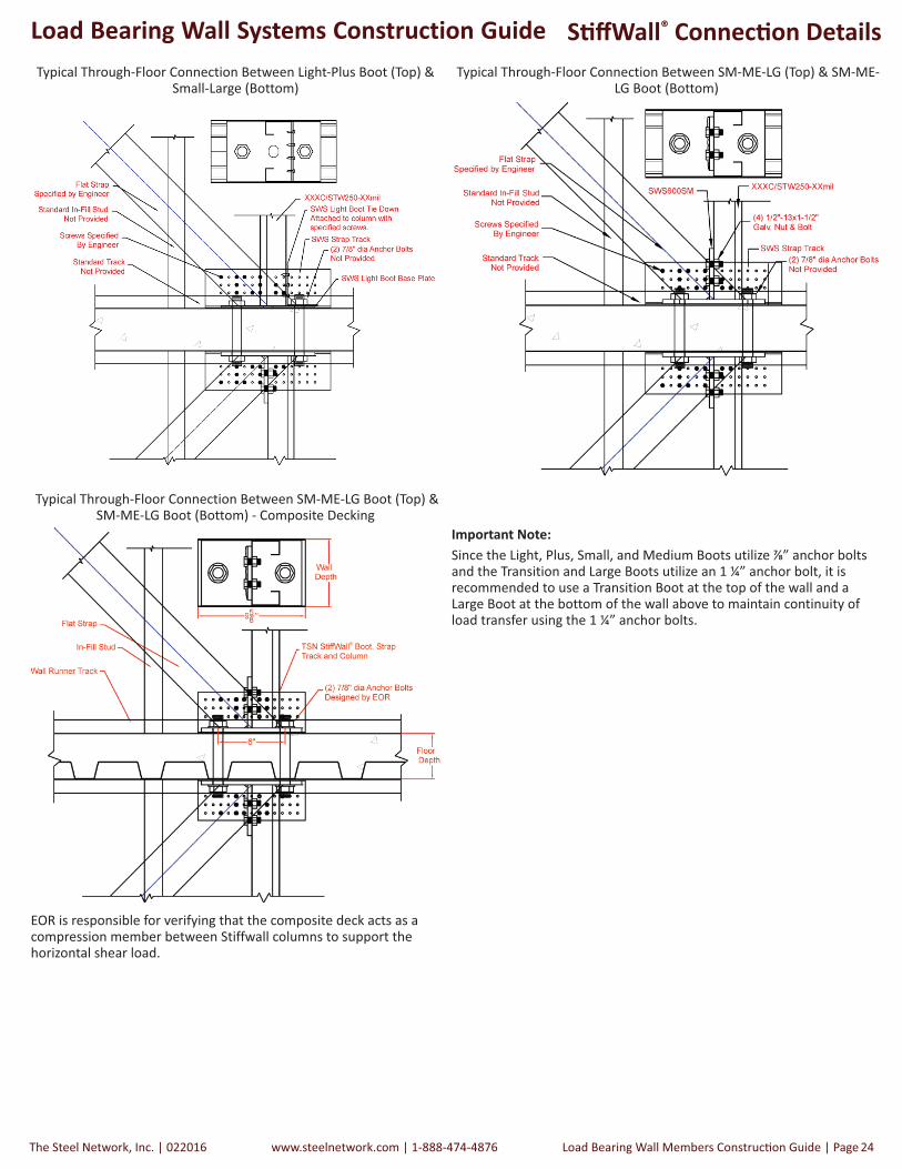
Typical Through-Floor Connection Between Light-Plus Boot (Top) & Small-Large (Bottom)
Typical Through-Floor Connection Between SM-ME-LG (Top) & SM-ME-LG Boot (Bottom)
EOR is responsible for verifying that the composite deck acts as a compression member between Stiffwall columns to support the horizontal shear load.
Important Note:
Since the Light, Plus, Small, and Medium Boots utilize ” anchor bolts and the Transition and Large Boots utilize an 1 ¼” anchor bolt, it is recommended to use a Transition Boot at the top of the wall and a Large Boot at the bottom of the wall above to maintain continuity of load transfer using the 1 ¼” anchor bolts.
Typical Through-Floor Connection Between SM-ME-LG Boot (Top) &SM-ME-LG Boot (Bottom) - Composite Decking

022016| The Steel Network, Inc.www.steelnetwork.com | 1-888-474-4876Page | Load Bearing Wall Systems Construc� on Guide25
Load Bearing Wall Systems Construction Guide S� � Wall® Connec� on Details
Typical Through-Floor Connection Between Boot B-E (Top) And Boot B-E (Bottom) - Double Column Back to Back
Multi-Story Detail - Medium, Transition & Large Boots
I�� ����� N ��:Double column sec� ons should be a� ached
together with a weld, bolts or screws at a
maximum interval of 24” o.c.
If using a Large Boot in a lower � oor, use a Transi� on Boot at the base of the next � oor to maintain con� nuity of 1 ¼” through-� oor
fasteners.
Medium Boot
Large Boot
Large Boot
Transi� on Boot
When S� � Wall terminates into Structural Steel, a� ach the shear wall to the red iron with an approved method. The details below are one example, and must also be approved by the Engineer of
Record.

The Steel Network, Inc. | 022016 www.steelnetwork.com | 1-888-474-4876 Load Bearing Wall Members Construc� on Guide | Page 26
Load Bearing Wall Systems Construction Guide
Product DescriptionThe pre-tensioning of a shear wall flat strap provides a means to ensure the shear wall will perform as designed. It is important that the flat straps are as tight as possible when installed to achieve optimal system performance.
TightStrap® is a unique device used to tension (tighten) flat strap in the field. Use TightStrap to improve structural performance of a shear wall by removing “waviness” or “bowing” prior to fastening.
TightStrap is designed to be used in both StiffWall® and generic flat strap shear walls. TightStrap’s track connector fastens to standard track at the corners of the shear wall to provide a base for the tensioning process. It is preferable to tighten the flat straps after applying some vertical load (own weight) on top of the shear wall panel. View the animated installation procedure at www.steelnetwork.com.
Using TightStrap®
Tightstrap®
Step 1 - Align & trim flat strap at each corner, attach one end with at least 2
screws.
Step 2 - Align Track Connector and attach to track.
Step 4 - Engage Bar Clamp, install at least 2 screws for flat strap attachment, remove TightStrap and install remaining screws for strap attachment.
Patent Pending
How to Install the S� � Wall® Shear Wall:The boots are a� ached to the founda� on or � oor and the roof or ceiling with approved anchors or bolts as determined and approved by the Engineer (Boots are made up of the Strap Track and the “T” shaped Base Plate)
• Light, Small & Medium Boots u� lize a ” anchor bolt or threaded rod. • Transi� on and Large Boots u� lize a 1 ¼” anchor bolt or threaded rod. • A� ach the Flat Strap to the Strap Track, corner to corner, on both sides (4 straps needed) with the speci� ed amount of #12 screws (or weld). The use of low pro� le screws help to reduce a “bump out” of � nished sheetrock. To achieve the designed loads, the strap should be � ght from corner to corner (with no slack). This is done by � ghtening the strap a� er the wall is loaded with a TightStrap® tool.
022016| The Steel Network, Inc.www.steelnetwork.com | 1-888-474-4876Page | Load Bearing Wall Systems Construc� on Guide27
Load Bearing Wall Systems Construction Guide
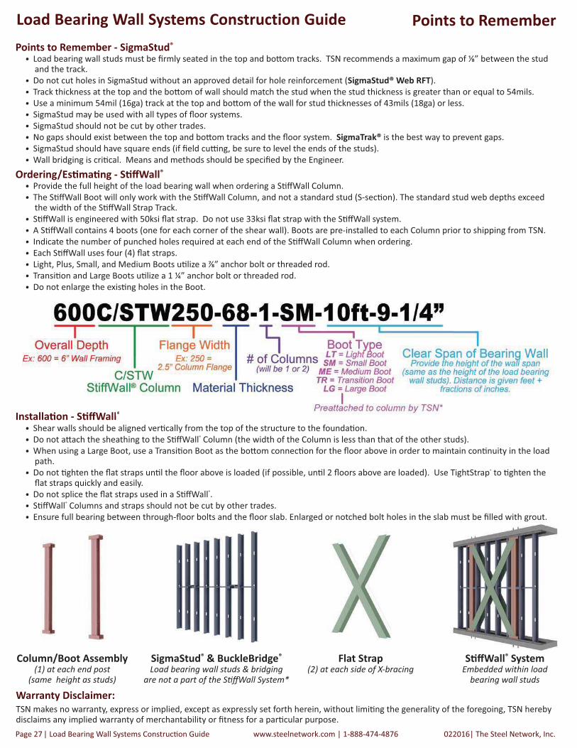
Ordering/Es� ma� ng - S� � Wall®
• Provide the full height of the load bearing wall when ordering a S� � Wall Column.
• The S� � Wall Boot will only work with the S� � Wall Column, and not a standard stud (S-sec� on). The standard stud web depths exceed the width of the S� � Wall Strap Track.
• S� � Wall is engineered with 50ksi � at strap. Do not use 33ksi � at strap with the S� � Wall system.
• A S� � Wall contains 4 boots (one for each corner of the shear wall). Boots are pre-installed to each Column prior to shipping from TSN.
• Indicate the number of punched holes required at each end of the S� � Wall Column when ordering.
• Each S� � Wall uses four (4) � at straps.
• Light, Plus, Small, and Medium Boots u� lize a ” anchor bolt or threaded rod.
• Transi� on and Large Boots u� lize a 1 ¼” anchor bolt or threaded rod.
• Do not enlarge the exis� ng holes in the Boot.
• Load bearing wall studs must be � rmly seated in the top and bo� om tracks. TSN recommends a maximum gap of �” between the stud and the track.
• Do not cut holes in SigmaStud without an approved detail for hole reinforcement (SigmaStud® Web RFT).
• Track thickness at the top and the bo� om of wall should match the stud when the stud thickness is greater than or equal to 54mils.
• Use a minimum 54mil (16ga) track at the top and bo� om of the wall for stud thicknesses of 43mils (18ga) or less.
• SigmaStud may be used with all types of � oor systems.
• SigmaStud should not be cut by other trades.
• No gaps should exist between the top and bo� om tracks and the � oor system. SigmaTrak® is the best way to prevent gaps.
• SigmaStud should have square ends (if � eld cu� ng, be sure to level the ends of the studs).
• Wall bridging is cri� cal. Means and methods should be speci� ed by the Engineer.
Installa� on - S� � Wall®
• Shear walls should be aligned ver� cally from the top of the structure to the founda� on.
• Do not a� ach the sheathing to the S� � Wall® Column (the width of the Column is less than that of the other studs).
• When using a Large Boot, use a Transi� on Boot as the bo� om connec� on for the � oor above in order to maintain con� nuity in the load path.
• Do not � ghten the � at straps un� l the � oor above is loaded (if possible, un� l 2 � oors above are loaded). Use TightStrap® to � ghten the � at straps quickly and easily.
• Do not splice the � at straps used in a S� � Wall®.
• S� � Wall® Columns and straps should not be cut by other trades.
• Ensure full bearing between through-� oor bolts and the � oor slab. Enlarged or notched bolt holes in the slab must be � lled with grout.
Points to Remember - SigmaStud®
Warranty Disclaimer:
TSN makes no warranty, express or implied, except as expressly set forth herein, without limi� ng the generality of the foregoing, TSN hereby disclaims any implied warranty of merchantability or � tness for a par� cular purpose.
Points to Remember
Column/Boot Assembly(1) at each end post
(same height as studs)
SigmaStud® & BuckleBridge®
Load bearing wall studs & bridgingare not a part of the S� � Wall System*
Flat Strap(2) at each side of X-bracing
S� � Wall® SystemEmbedded within load
bearing wall studs
Installa�on S��Wall®

The Steel Network, Inc. | 022016 www.steelnetwork.com | 1-888-474-4876 Load Bearing Wall Members Construc� on Guide | Page 28
Load Bearing Wall Systems Construction Guide Warranty
Products in this catalog are designed and manufactured for the specific purposes shown, and should not be used in other applications unless approved by a qualified design professional. All modifications to products or changes in installation procedures should be made by a qualified design professional. The performance of such modified products or altered installation procedures is the sole responsibility of the design professional or installation contractor. The installation contractor and/or qualified design professional are responsible for installing all products in accordance with relevant specifications and building codes.
Customers modifying products or installation procedures, or designing non-standard products for fabrication by The Steel Network, Inc. ("TSN") shall, regardless of specific instructions to the user, indemnify, defend, and hold TSN harmless for any and all claimed loss or damage occasioned in whole or in part by non-standard or modified products or installation procedures.
Loads published on TSN’s website and current product catalogs are for the described specific applications of properly installed products. Modifications to TSN products, improper loading or installation procedures, or deviations from recommended applications will affect TSN products' load-carrying capacities. TSN products are fabricated from hot-dipped galvanized steel for corrosion protection but will corrode and lose load-carrying capacity if exposed to salt air, corrosive fire-retardant chemicals, fertilizers, or other substances that may adversely affect steel or its galvanized coating. The current editions of TSN’s catalogs and load tables published on this website may reflect changes in the allowable loads and configurations of some of TSN's products. This information supersedes information in earlier catalogs or technical reports. All earlier catalogs or technical reports should be discarded and reference made exclusively to the versions available at http://www.steelnetwork.com/Site/Catalogs. TSN may correct any clerical or typographical errors. All sales are subject to TSN's standard terms and conditions of sale.
BackIt®, BridgeBar®, BridgeClip®, BuckleBridge®, CircleTrak®, DriftClip®, DriftCorner®, DriftTrak®, GripClip®, JAM600™, JAM800™, JamStud®, MasterClip™, MidWall™, NotchTrak®, PrimeWall®, SG600™, SG800™, SigmaStud®, SigmaTrak®, Step-Bushing Technology™, StiffClip®, StiffWall®, TightStrap®, VertiClip® and VertiTrack® are trademarked products, and are patented or patent-pending technologies of TSN. Patent numbers are: #5,467,566; #5,904,023; #5,906,080; #6,612,087; #6,701,689; #6,892,504; #7,104,024; #7,503,150; #7,559,519; #7,596,921; #7,634,889; # 7,788,878; #7,832,162; #7,836,657; # 8,132,383; #8,181,419; #8,205,402; #8,387,321 and #8,683,770. Numerous TSN design configurations are patented and/or patent pending and are protected under US and International patent laws.
TSN warrants its products to be free from defects in material or workmanship at the time of shipment. TSN standard catalog products are warranted for adequacy of design when used in accordance with design limits in this catalog and properly specified and installed. TSN products shall not be substituted with non-TSN products if it is part of a system. Substitution of a TSN product will immediately void any warranty claim made by Purchaser. This warranty excludes uses not in compliance with specific applications and installation procedures set forth in this catalog. Warranty claims must be made by Purchaser in writing within ninety (90) days of receipt of the products.
All warranty obligations of TSN shall be limited, at the sole discretion of TSN, to repair or replace the defective product(s). These remedies shall constitute TSN's sole obligation and sole remedy of purchaser under this warranty. In no event will TSN be responsible for incidental, consequential, indirect, exemplary, incidental, special, consequential, or punitive damages, or other losses or damages however caused, including, but not limited to, installation costs, lost revenue or lost profits. TSN's liability for damages shall in no event exceed the applicable portion of the purchase price for defective product(s).
Product defects that arise from acts of God, accidents, misuse, misapplication, improper installation, storage damage, negligence, or modification to product(s) or its components are specifically excluded from this warranty. Product defects that arise from Purchaser providing incorrect information to TSN, including but not limited to incorrect specifications such as incorrect dimensions, designs and/or loads, are also specifically excluded from this warranty. TSN does not authorize any person or party to assume or create for it any other obligation or liability in connection with Products except as set forth herein.
This Warranty is expressly in lieu of all other warranties, expressed or implied, including any warranties of merchantability or fitness for a particular purpose, all such other warranties being hereby expressly excluded.
Toll Free Nationwide Phone (888) 474-4876
Web Site: www.steelnetwork.comE-mail: [email protected]
Copyright © 2016 The Steel Network Inc. All rights reserved. No part of this publication may be reproduced in whole or in part by any method without the prior written consent
of The Steel Network, Inc.
Product Use
Limited Warranty
Patented Technology
Contact Information
TSN Corporate Headquarters2012 TW Alexander Drive
P.O. Box 13997Durham, NC 27709
Phone: (919) 845-1025Fax: (888) 474-4877
1650 Helm DriveSuite 1000 -1200
Las Vegas, NV 89119Phone: (702) 643-4330
Fax: (702) 643-4331
North Carolina Nevada