Embed Size (px)
Citation preview

10th International Conference on Fracture Mechanics of Concrete and Concrete Structures
FraMCoS-X G. Pijaudier-Cabot, P. Grassl and C. La Borderie (Eds)
Behaviour of Reinforced Concrete Squat Shear Walls with Utility Openings
V. SIVAGURU*AND G. APPA RAO
†
*Indian Institute of Technology Madras, India
e-mail: [email protected]
† Indian Institute of Technology Madras, India
e-mail: [email protected]
Key words: Shear wall, Wall openings, Shear strength, Fiber Reinforced Concrete (FRC).
Abstract: Reinforced concrete (RC) squat walls are often encountered for various inevitable
purposes in many civil engineering structures, which play role on failure due to lateral forces
produced by seismic, wind and explosive loads. This paper discusses on some investigations on RC
squat walls with openings in comparison with controlled walls without openings. Experimental
studies have been carried out on RC shear walls with and without openings. The walls under gravity
loads were tested under lateral loads due to the effect of earthquake motions on buildings. The
lateral strength and load transfer mechanism have been significantly altered with the provision of
utility openings in RC walls. The shear strength and load transfer paths have been evaluated through
nonlinear finite element analysis of RC walls with and without openings for validating the
experimental results. Plain concrete is modelled as multi linear isotropic material using SOLID65
element, which captures plastic deformation, cracking in three orthogonal directions, and crushing.
The reinforcement bars are modelled as discrete bilinear elements using LINK8 element. In order to
control the cracking of concrete in corner regions of openings, fibre reinforced concrete (FRC) was
adopted, in which the steel fibres were smeared. The addition of steel fibres improves the shear
strength by 60%. The confinement and cracking resistance of concrete have been significantly
improved by FRC, exhibiting that is an efficient solution for mitigating the stress concentration
induced cracking in RC walls with openings.
1 INTRODUCTION
Reinforced concrete shear walls are
effective in resisting, and transferring lateral
loads from earthquake and wind loads on
structural system. They efficiently control the
construction cost and damage due to
earthquakes in structural system. During the
past few decades, a considerable improvement
has been noticed in the design and
construction of RC walls. Behaviour of such
shear walls primarily depends up on the ratio
of applied moment-to-applied shear force. This
ratio linearly corresponds to the aspect ratio
(A/R) of the shear wall; which is the ratio of
height-to-length of wall.
Shear walls can exhibit cantilever action as
in slender or high rise walls (with A/R > 2)
and by truss action in squat/short or low rise
walls (with A/R<2). Slender walls
predominantly fail in flexure, while squat
walls fail in shear. Local buckling of web can
be minimized by boundary elements at the
wall ends with minimum web thickness. It has
been observed that boundary elements, aspect
ratio, wall thickness, reinforcement ratio, yield
strength of steel, compressive strength of
concrete, and applied axial stress showed
significant influence on the shear strength of
shear walls and seismic performance in terms
of stiffness degradation, energy dissipation,

V. Sivaguru and G. Appa Rao
crack patterns and modes of failure.
Practically, openings in shear walls are
inevitable in the form of doors, windows or
some other functional requirements, whose
influence is tremendous under seismic loading.
These shear walls with openings are
recommended as per the codes with additional
corner reinforcement around the openings,
whose area is equal to the area of interrupted
bars. Some codes do not have such
recommendations.
2 RESEARCH SIGNIFICANCE
The information on behaviour of RC squat
shear walls with openings is very limited. The
seismic response is significantly affected by
the size of openings and their location in the
wall. Hence, the research on behaviour and
strengthening of walls with openings is an
important issue. Also, investigation for various
measures of strengthening of shear walls with
openings using FRC or other materials is
gaining importance. Hence, such research
efforts are needed at this juncture. This study
presents the numerical analysis of shear walls
with openings using FRC to be used as
strengthening agent around the opening.
3 NUMERICAL STUDY
In the present study the finite element
package ANSYS 15.0 is used for modelling.
The package delivers greater accuracy,
fidelity, higher productivity and more
computational power. The region around the
opening is vulnerable due to stress
concentration and severe cracking. Instead of
providing FRC throughout, it is recommended
only to certain vertical distance around the
opening. The spread of FRC from opening
edge is vertically varied as 0.0 mm, 50 mm,
100 mm, 150 mm, 200 mm and 300 mm.
Figure 1 shows the addition of FRC around
opening up to a depth of 150 mm from
opening edge in the present study. This study
is carried out in ANSYS15.0.
Figure 1: Fibre Reinforced Concrete (FRC) around
opening
It has been recognised that effect of FRC
around opening exhibited only up to a certain
vertical distance from the edge of opening.
Table 1 shows the shear strength of shear wall
with FRC around the opening with varying
vertical distance from edge of opening.
The geometry of the wall is shown in Figure 2.
Figure 2a: Geometry of the Wall
Figure 2b: Reinforcement Details of the Wall

V. Sivaguru and G. Appa Rao
Three types of elements were adopted for
modelling the shear walls. Eight noded
SOLID65 (Concret65) elements for modelling
concrete, two noded LINK 8 elements for
modelling reinforcement and eight noded solid
185 elements for modelling loading steel plate.
FRC was modelled as concrete with smeared
fibre property with different orientation angle.
The reinforcement and steel plate used in the
study are assumed to exhibit elasto-plastic
response with identical properties in tension
and compression. Modelling of concrete
behaviour is a difficult task due to its quasi-
brittle material response and exhibiting
different behaviour in compression and
tension. SOLID65 element was developed
exclusively for concrete. The portions of FRC
in the wall are modelled by smeared concrete
model. The mesh convergence study
performed to find the appropriate mesh size
was found to be 25 mm. A nonlinear structural analysis was
performed to study the nonlinear material
behaviour of RC wall. ANSYS15.0 employs
“Newton-Raphson” method to solve nonlinear
problems. The load was sub-divided into series
of load increments as load steps. A nonlinear
structural analysis was performed to study the
nonlinear material behaviour of the wall.
ANSYS15.0 employs “Newton-Raphson”
method to solve nonlinear problems. The load
was sub-divided into series of load increments
as load steps. The large displacement static
condition considered for analysis and the
tolerance limits are kept in the order of 10-2.
Failure of the model identified where the
solution fails to converge even with very low
load increment.
The load was sub-divided into series of load
increments as load steps. The large
displacement static condition is considered for
analysis and the tolerance limits are kept in the
order of 10-2. Failure of the model is
identified where the solution fails to converge
even with very low load increment.
Figure 3: Rebar Model in ANSYS in RC walls.
Figure 4: Load - Deflection response in RC wall with
varying depth of FRC
Table 1: Strength of wall with varying depth of FRC
No
Opening
Depth of FRC from Opening (mm)
0 50 100 150 200 300
Shear Strength (kN) 353 162 180 216 252 270 283.5
Percentage of strength
compared with wall
without opening
1 32 36 43 50 54 56
0
50
100
150
200
250
300
350
400
0 1 2 3 4 5 6 7
Late
ral
Loa
d (k
N)
Lateral Displacement (mm)
WO (FRC - 0 mm Depth)
WO (FRC - 50 mm Depth)
WO (FRC - 100 mm Depth)
WO (FRC - 150 mm Depth)
WO (FRC - 200 mm Depth)
WO (FRC - 300 mm Depth)
Series8

10th International Conference on Fracture Mechanics of Concrete and Concrete Structures
FraMCoS-X G. Pijaudier-Cabot, P. Grassl and C. La Borderie (Eds)
The load-deflection response of the wall
with varying vertical distance of FRC is
reported in Figure 4. It has been observed that
the addition of FRC around the opening
improves not only the strength but also the
lateral stiffness of the wall up to certain extent.
It was also be noticed that the addition of FRC
beyond 150 mm distance away from the edge
of opening does not show much variation in
strength and lateral stiffness of the wall.
In RC walls without opening, first crack
was observed at the top left corner and slowly
developed as diagonal crack. Simultaneously,
the crack was observed at the bottom of the
wall as well. In the wall with window opening,
the first crack was observed at the top left
corner of the opening and progressed gradually
towards the corner of the wall. Meanwhile,
another crack started at the bottom right corner
of the opening and developed towards the
bottom right corner of the wall.
Figure 5: Crack Pattern of shear wall without opening
(Left) and with opening (Right)
4 EXPERIMENTAL STUDY
4.1 Geometry of specimen
The test series includes three one-third
scaled reinforced concrete squat shear wall
with and without opening. It is presumed that
the tested cantilever wall subjected to constant
vertical load and static cyclic lateral load
exhibits similar behaviour of shear wall under
earthquake loading. The shear wall consists of
three components. The first component is the
top beam through which the vertical and
lateral loads are transferred to the wall. The
second component is the wall web. The third
component is the bottom beam which anchors
to the strong floor for fixity. The three shear
walls designed for the experimental study
includes: shear wall without opening (SW-
1.0), shear wall with concentric window
opening (SW-1.0-CW) and shear wall with
concentric window opening with FRC (SW-
1.0-CW-FRC).
Figure 6: Geometric details of the specimen
V. Sivaguru and G. Appa Rao
Table 2 Geometrical details of RC Shear wall for Experimental Programme
S.
No Specimen ID
L
mm
H
mm
T
mm
Boundary
Elements Opening
ρl
%
ρh
%
ρB
E
%
fy
MPa
fck
MPa
N
kN l
mm
h
mm
a
mm
b
mm
1 SW–1.0 1000 1000 125 300 150 - - 0.4 0.4 1 500 24 200
2 SW-1.0–CW – IS 1000 1000 125 300 150 300 300 0.4 0.4 1 500 26 200
3 SW–1.0–CW- FRC 1000 1000 125 300 150 300 300 0.4 0.4 1 500 24 200
All shear walls have same geometric
dimension. The Top beam has a length of 1600
mm and cross section of 300 mm x 400 mm.
The wall portion has length of 1000 mm,
height of 1000 mm and thickness of 125 mm.
The length and breadth of boundary elements
are 300 mm and 150 mm respectively. The
bottom beam has a length of 2500 mm and
cross section of 500 mm x 600 mm. The
bottom beam and top beam are designed to
possess sufficient stiffness to bear and transfer
forces with negligible deformation. The
reinforcement details which are listed in Table
2 are provided as per the requirements
IS13920:2014. The details of the shear walls
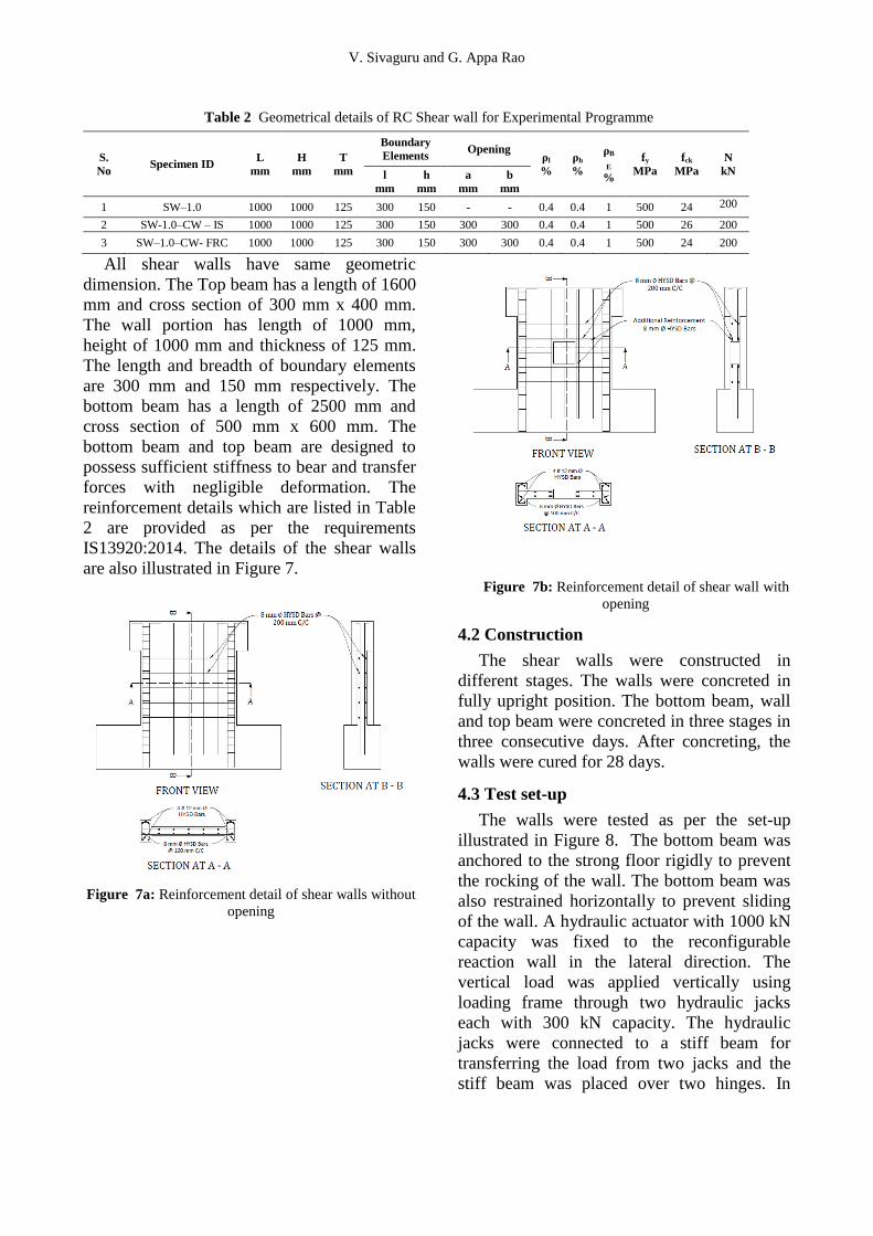
are also illustrated in Figure 7.
Figure 7a: Reinforcement detail of shear walls without
opening
Figure 7b: Reinforcement detail of shear wall with
opening
4.2 Construction
The shear walls were constructed in
different stages. The walls were concreted in
fully upright position. The bottom beam, wall
and top beam were concreted in three stages in
three consecutive days. After concreting, the
walls were cured for 28 days.
4.3 Test set-up
The walls were tested as per the set-up
illustrated in Figure 8. The bottom beam was
anchored to the strong floor rigidly to prevent
the rocking of the wall. The bottom beam was
also restrained horizontally to prevent sliding
of the wall. A hydraulic actuator with 1000 kN
capacity was fixed to the reconfigurable
reaction wall in the lateral direction. The
vertical load was applied vertically using
loading frame through two hydraulic jacks
each with 300 kN capacity. The hydraulic
jacks were connected to a stiff beam for
transferring the load from two jacks and the
stiff beam was placed over two hinges. In

V. Sivaguru and G. Appa Rao
-20
-10
0
10
20
0 10 20 30 40
Late
ral
Drif
t (%
)
Number of Load Cycles
addition to that, a spreader beam was placed
on the top of the wall to make sure that vertical
load was applied uniformly to the wall.
Figure 8: Test Setup
4.4 Loading procedure
The vertical load was kept constant
throughout the testing maintaining the axial
load ratio (ALR) as 10%. Cyclic lateral
loading was accompanied by a displacement
control system as per ASTM E2126-11. As per
ASTM E2126-11, first displacement pattern
comprises of five single cycles at displacements of
1.25, 2.5, 5, 7.5 and 10%, and second displacement
pattern comprises of three fully reversed cycle
starting from 20, 40, 60, 80 ,100, 120% and so on as illustrated in Figure 9, until failure or up to
10% lateral drift (i.e. 10 mm).
Figure 9: Loading Protocol
5 EXPERIMENTAL RESULTS
5.1 Wall without opening (SW–1.0)
The first horizontal cracking was noticed in
the upper half of boundary element during
0.4% drift. In the following loading stages, the
horizontal crack formed at boundary element
inclines towards opposite toe of the web of the
wall. Many short inclined cracks developed in
the web portion of the wall. The crack pattern
in the wall at the peak and failure load is
shown in Figure 10. At the failure load, the
crushing of concrete in both left and right toes
of boundary elements was observed under both
positive and negative cycles. Peak loads of
+541.06 kN and -455.853 kN were observed
with corresponding drift values of +2.34% and
-1.82% respectively.
a. Positive Cycle
b. Negative Cycle
Figure 10: Crack pattern at Peak Load for SW-1.0

V. Sivaguru and G. Appa Rao
Figure 11: Crack pattern at Failure Load in SW-1.0
5.2 Wall with window opening (SW-1.0-
CW-IS)
The first crack was observed at top corner
of the opening and develops diagonally
towards the top corner of the wall during 0.2%
drift cycle. On further loading, cracks from all
the four corners of the opening were formed
and developed towards the nearest corners of
the wall. The crack pattern of the wall at the
peak and failure load is shown in Figure 12
and Figure 13. At the failure load, the weak
plane near opening was sheared off
horizontally. Peak loads of +292.65 kN and -
289.38 kN were observed at drift values of
+2.00% and -2.05% respectively.
Figure 12: Crack pattern at Peak Load in SW-1.0-CW-IS
Figure 13: Crack pattern at Failure Load in SW-1.0-CW-
IS
5.3 Wall with window opening with FRC
(SW-1.0–CW–FRC)
This wall was designed with FRC around
the opening, where the wall is highly prone to
stress concentration. The first cracking was
observed at top corner of opening and
developed diagonally towards the top corner of
the wall at 0.2% drift. Almost same crack
pattern was observed similar to the wall with
window opening without FRC at initial stages.
On loading, the cracks from all the four
corners of the opening were formed and
developed towards the nearest corners of the
wall. The crack pattern of the wall at the peak
and failure load is shown in Figure 14. At the
failure load, the crushing of concrete in both
left and right toes of boundary elements was
observed in both positive and negative cycles
as observed in wall without opening. Peak
loads of +519.75 kN and -428.77 kN were
observed with corresponding drift values of
+2.26% and -2.27% respectively.
Figure 14: Crack pattern at Peak Load in SW-1.0-CW-
FRC

V. Sivaguru and G. Appa Rao
Figure 15: Crack pattern at Failure Load for Wall 3
5.4 Discussion of test results
The Load vs. Drift response in all three
walls are shown in Figures 16. The strength,
displacement and ductility of the specimen
were listed in Table 3. The drift capacity of the
wall with opening was lesser than the wall
without opening. However, it was improved by
the adding FRC around the opening. It is to
note that the shear capacity of the shear wall
has been drastically affected by the presence
of opening. The shear capacity of the wall
without opening has been observed to be 498
kN. The shear capacity of the wall with
opening has been observed to be 291 kN
where 42% of reduction in the strength is
noted. The shear capacity of wall with window
opening with FRC has been observed to be
474 kN. Addition of FRC around the opening
improves the strength by 61%. Moreover, the
failure pattern of the wall changed completely
with the presence of FRC.
Wall SW-1.0
Wall SW-1.0-CW-IS
Wall SW-1.0-CW-FRC
Figure 16: Load vs. Drift response in shear walls under
static cyclic tests
6. CONCLUSION
The following conclusions have been drawn
from this study,
1. The shear strength and ductility of shear
wall have been reduced drastically due to
presence of opening in the wall.
Table 3 Test Results
Specimen Vpeak
+
(kN)
Vpeak-
(kN)
VPeak
(kN)
τmax
(MPa)
Δpeak/H
(mm)
Δu/H
(mm) μ
SW-1.0 541 -456 498 2.32 0.7 2.34 3.34
SW-1.0-CW-IS 293 -289 291 1.35 1.58 2.00 1.27
SW-1.0-CW-FRC 520 -429 474 2.21 1.46 2.26 1.55

V. Sivaguru and G. Appa Rao
2. The addition of FRC around the opening
improves the shear strength by 61% and
ductility by 18%.
3. For the wall with opening, the failure mode
has been due to shearing off the weaker
plane of the wall (i.e) across the opening.
For the wall without opening and with
opening with the addition of FRC, the
failure mode occurred due to crushing of
concrete at both left and right toes of
boundary elements. Interestingly, the
addition of FRC around the opening alters
the cracking pattern of the wall.
4. The extent of FRC from the edge of
opening along height of wall to half width of
opening seems to exhibit improved
response.
5. Use of FRC is an alternate solution for
strengthening of shear wall with opening.
REFERENCES
[1] ACI 318 2014. Building code
requirements for structural concrete.
american concrete institute, rarmington
hill, michigan.
[2] Barda, F., Hanson, J. M., and Corley, W.
G., 1977.“Shear strength of low-rise walls
with boundary elements”, sp-53, american
concret institute, detroit, v-53, pp. 149-
202.
[3] IS: 13920: 2016 - ductile detailing of rc
structures subjected to seismic forces-
code of practice
[4] Lin, C.V, and Kuo C. L., 1988. Behaviour
of shear walls with opening. in: proc. Of
the ninth world conf. On earthquake eng.,
v-4, pp. 535–540.
[5] Marius, M., 2014. Failure analysis of RC
walls with staggered openings under
seismic loads. Engineering Failure
Analysis, V-41, pp. 48-64.
[6] Mazen, A, M., 2013. Analysis of Shear
Walls with Opening using Solid65
Element. Jordan Journal of Civil
Engineering, V-7, No. 2, pp. 164-173.
[7] Musmer, M. A., 2013. Analysis of Shear
Wall with Openings Using Solid65
Element. Jordan Journal of Civil
engineering, V-7, No. 2, pp. 164 – 173.
[8] Wood, S. L., 1990. Shear strength of Low-
Rise Rein. Concrete walls. ACI Str Jl, V-
87, pp. 99-107.
[9] Paulay, T., and Loeber, P. J., 1974. Shear
Transfer by Aggregate Interlock. ACI
Structural Journal, V-42, pp. 1-15.
[10] Gulec, C. K., Andrew, S.W., and Bozidar,
S. 2009. Peak Shear Strength of Squat
Reinforced Concrete Walls with Boundary
Barbells or Flanges. ACI Structural
Journal; V-106, No. 3, pp. 368-377.