Embed Size (px)
Citation preview
Fracture Mechanics of Concrete Structures, de Borst et al {eds)© 2001 Swets & Zeit!inger, Lisse, ISBN 90 2651 825 0
Validation of non linear constitutive laws used for the seismic evaluation of
existing industrial facilities
D.Combescure & P.Sollogoub Seismic Mechanic Study Laboratory, DEN/DM2S/SEMT, CEA Saclay, 91191 GiflYvette Cedex, France
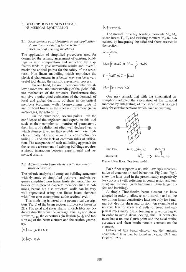
ABSTRACT: In the oldest industrial countries specially with moderate seismicity such as France, the main part of the building stock has been designed before the application of the modern seismic code. Because of the absence of any seismic consideration at the period of the construction or the modification of the action levels, many reinforced concrete structures do not satisfy the actual requirements. Due to safety reasons, the case of industrial and nuclear facilities and plants may be critical and requires detailed seismic evaluations. The application of simplified procedures used for design tends to give umealistic results and, overall, masks the critical points for the facility safety. This paper aims at presenting some validation of non-linear modelling used for the seismic evaluation of existing nuclear facilities. The fibre type beam model used for this seismic assessment has non linear constitutive laws for concrete, steel and anchorage/splices and non linear behaviour in shear. This modelling approach has been applied to the modelling of RIC frame structures and beam column joints tested during several experimental campaigns described in the literature.
1 INTRODUCTION In the oldest industrial countries specially with
moderate seismicity such as France, the main part of the building stock has been designed before the application of the modern seismic code. Because of the absence of any seismic consideration at the period of the construction or the modification of the action levels, many reinforced concrete structures do not satisfy the actual requirements: inadequate stirrups spacing, insufficient lengths of anchorage and lap splices, low shear strength of columns or beamcolumn joints compared to the shear demand imposed by the global flexural mechanism ...
Due to safety reasons, the case of industrial and nuclear facilities and plants may be critical and requires detailed seismic evaluations. The application of simplified procedures used for design tends to give umealistic results and, overall, masks the critical points for the facility safety.
The seismic assessment of the RC frames can be performed using a non linear fibre type model. This model supported by a Timoshenko beam element with shear distortion is based on classical beam assumptions and uses uniaxial constitutive laws for concrete and steel. The strength of the brittle mechanisms - the modern seismic code intends to avoidcan also be checked using appropriate material laws and modelling assumptions.
This paper aimed at presenting some validation of these constitutive laws on experimental results avail-
887
able in the literature. The main principles of the modelling (type of finite elements, constitutive laws,. .. ) will be reminded before the detailed analysis of the tests on elementary structural elements (columns and beam-column joints).
Firstly, some consideration about the modelling of the bending behaviour will be made specially on the failure criteria (length of plastic hinge to be used, influence of the detailing on the failure criteria, etc ... ).
In a second step, the simplified laws used for shear behaviour and the modelling of anchorage and lap splices will be particularly detailed. A simple model based on the equilibrium between the bond stress between concrete and steel and the axial stress in the steel bar is used for the verification of the anchorage and the lap splices. Furthermore a way to compute and check the shear strength of the beamcolumn joint using only simple beam elements will be described.
Finally a comparison between numerical and experimental results will be made in order to validate the modelling approach. The experimental results used for this validation are part of testing campaigns performed in the United States on isolated structural elements under cyclic loading. RC columns with insufficient shear strength and lap splices and beamcolumn joints with insufficient anchorage length of the bottom beam steel bars were concerned by these experiments.
2 DESCRIPTION OF NON LINEAR NUMERICAL MODELLING
2.1 Some general considerations on the application of non linear modeling to the seismic assessment of existing structures
The application of simplified procedures used for design for the seismic assessment of existing buildings -elastic computation and reduction by a qfactor- tends to give umealistic results and, overall, masks the critical points for the safety of the structures. Non linear modelling which reproduce the physical phenomena in a better way can be a very useful tool during the seismic assessment process.
On one hand, the non linear computations allow a more realistic understanding of the global failure mechanism of the structure. Furthermore they can give a quite good estimation of the demands of local and global ductility, of shear in the critical members (columns, walls, beam-column joints ... ) and of bond forces in the steel reinforcement (rebar anchorages, lap splices ... ).
On the other hand, several points limit the confidence of the engineers and experts in this tool such as their complexity -number of parameters-, their limits of validity not often well declared -up to which damage level are they reliable and these models can really take into account the consh·uction detailing ? - and the lack of common rules of utilisation. The acceptance of such modelling approach for the seismic assessment of existing buildings requires a strong interaction between experimental and numerical results.
2.2 A Timoshenko beam element with non linear shear behaviour
The seismic analysis of complete building structures with dynamic or simplified push-over analysis requires simplified non linear finite elements. The behavior of reinforced concrete members such as columns, beams but also structural walls can be very well reproduced using non linear beam elements with fiber type assumptions at the section level.
This modeling is based on a geometrical description (Fig 1) of the beam section in fibers (or layers in 2D). The axial and shear strains in each fiber are deduced directly from the average axial Ex and shear strains Yy, y2 , the curvatures (in flexion ~y, ~z and torsion ~x) of the beam element and the section geometry.
(i:x );=&x-y;·r/Jz+Z;·rpy
888
The normal force Nx, bending moments My, Mz, shear forces Ty, T2 and twisting moment Mx are calculated by integrating the axial and shear stresses in the section.
My= fz ·CJxdS et Mz=-fy ·CJxdS s s
Ty= frydS et Tz = fr,dS s s
Mx= fCY ·Tz-z.Ty)dS s
One may remark that with the kinematical assumptions adopted the calculation of the torsional moment by integrating of the shear stress is exact only for circular sections which have no warping.
Beam level: (u, 8)q (Eo,~,y) (M,N,T)
Fibre level: D
(c,y) => u (CJ xx, 't"X),, Txz)
Figure I. Non linear fiber beam model
Each fiber supports a uniaxial law cr( E) representative of concrete or steel behaviour. Fig 2 and Fig 3 show the laws used in the present study respectively for concrete (with softening in compression and tension) and for steel (with hardening, Bauschinger effect and buckling).
A simple Timoshenko beam element has been adopted in order to allow shear distortion and so the use of non linear constitutive laws not only for bending but also for shear and torsion. An example of a uniaxial law for shear i:(y) with softening and empirical rules under cyclic loading is given on Fig 4. In order to avoid shear locking, this 3D beam element has a unique Gauss point and the axial strain, curvature and shear strain remain constant on the element.
Details of this beam element and the uniaxial constitutive laws can be found in Pegon, 1993 and Guedes, 1997.

Stress cr MPa
CJ,o
E,o
a/ Behaviour in compression
z
Strain E
0,0000 0,0001 0,0002 0,0003 0,0004
bl Behaviour in traction Figure 2. Uniaxial constitutive law for concrete
Stress a (MPa)
Figure 3. Menegotto-Pinto uniaxial law with Bauschinger effect and buckling for steel
Shear stress 'txz
Figure 4. Uniaxial law with softening for shear behaviour
2.3 Some remarks on the influence of detailing on the modeling
The accuracy of the modeling and the prediction of failure depends strongly on the capacity to take into account of the construction detailing specially for the reinforced concrete frame structures.
For example, the concrete law shown Fig 2 although it is uniaxial can be directly influenced by the confinement of the stirrups by modifying the ultimate compressive strength and the softening slope Z. A decrease of softening due to higher confinement ratio improves the curvature ductility capacity. The confinement can also be taken into account by modi-
fying the local failure criteria (let say the concrete ultimate strain).
Another major difficulty in the modeling of frame structures up to flexural failure is the localization phenomena due to softening or limited hardening after yielding of the steel bars. This phenomena makes the local results (curvature and strain demands) strongly dependent on the mesh size and requires to fix the length of the elements -the plastic hingeswhere damage may concentrate. This is equivalent to consider plastic rotations or chord rotations as failure criteria.
Priestley, 1997 gives some formulae to determine the length of the plastic hinge Hhinge·
Hhinge = 0.08 Heolumn + 6 dbar This length depends not only on the column
height Heolumn but also on the steel bars diameter dbar since spread of steel yielding in the footing has been evidenced by several experimental results.
2.4 A constitutive law for anchorages and lap splices
A specific constitutive law for has been introduced in the fibre model in order to check the possible failure of lap splices and anchorages. The approach already implemented for bridge piers by Monti, 2000 and Xiao, 1997 has been adopted.
This uniaxial law cr(E) is based on the partition of the total strain E between the strain in the steel bar Es and the slippage between steel and concrete s (Fig Sa). This partition can be written incrementally:
889
LiE = LiEs + Lis/Lane· with
LiE,=A.LiE Lis =Lane·(l-A).LiE
Lane: Length of anchorage or splices A,: Partition factor between the 2 types of deformations.
The axial stress in the steel bar cr, and the bond stress -i: are given by 2 appropriate constitutive laws respectively for steel rebar cr,(Es) and for bond slip -i:(s). A law similar to the Eligehausen law has been adopted for bond slip (Fig 5-c, Eligehausen, 1993).
The partition factor A, can be calculated iteratively with the static equilibrium between the force in the steel bar Fsteel and the bond stress Fbond which is supposed constant on the complete length of the anchorage or lap splices (Fig 5-b). An iterative modified Newton-Raphton algorithm is used to verify the equilibrium.
LiF stee1+M bona=O=f(A,) The choice of the initial value of partition Ao be
tween steel strain and bond slip has a major influence on the robustness of the algorithm.

··············m··· ............. tL'"'·"'
WJ:. . ". u/ f(i11e11111tic ttSsumptions bl Stress distribution
cl Eligelumsen law fOr bomi slip
Figure 5. Phenomenological uniaxial Jaw for anchorage and lap splices
3 APPLICATION TO RC COLUMNS UNDER CYCLIC LOADING
3 .1 Experimental results
In a recent past, several experimental research programmes focused on the influence of detailing used between 1950 and 1980 in United States on the seismic behaviour of the structural members. The results of the tests performed by Aboutaha at Austin University on reinforced concrete columns under horizontal cyclic static loading have been used for the present study (Aboutaha, 1997).
Aboutaha realized a first series of tests on flexural columns (aspect ratio H/L=6) with square and rectangular sections characterized by insufficient lap splices: splice length of 20 diameters which used to be very common in US and only 2 stirrups in the lap splices region (Fig 6-a). Several columns have also been strengthened with different types of steel jacketing.
The second series of tests concerned shear columns with aspect ratio between 1.34 and 2.7 and insufficient initial shear reinforcement (Fig 6-b ). Several other specimens with steel jackets have also been tested and failed by flexion. The squat column SC9 considered in the present work failed by shear before developing its flexural strength (aspect ratio equal to 1.34). It must be precised another column tested by Aboutaha with a higher aspect ratio (2.7) failed by shear but after yielding of the flexural reinforcement. Such behaviour can not be predicted with the present constitutive law.
3.2 Application to the columns with insufficient lap splices
The fiber beam element has been applied to the modeling of the flexural column FC15 whose lap
'<- ~~ ~ ! "'8
~:i:
;,: !!!
~ 0 !!! !!! :x:
"' @) !ii' !!! "' Cl
" :;:
(e) Detalls of a Typical ~lexura! Column
o Starter Bar © Column Bar fl MG!n R6'!nl'Ofe3m:::nt # S Gr. 60
g 11ea83@16~Gr.40
" . Main Reinforcement 16/tS dr;60
o- 11esff'3@16•Gr.40
al FC IS Column with insufficient lap splices
" Maln Relnforcemerrt 16#a Gt.60
"' Ties fl 3@i6" Gr. 40
bl SC9 Column with insufficient shear strength Figure 6. Geometry and characteristics of columns with no seismic detailing
splices failed before developing the flexural strength of the section. A unique beam element and the special law for anchorage and lap splices have been considered for the plastic hinge at the base of the column.
The Priestley formulae gives a length of plastic hinge of 37.2 cm for a column height equal to 274.3 cm and diameter of the steel bars of25.4mm (#8).
The physical length of 20dbar has been considered for the lap splices. The bond characteristics recommended by Eligehausen for unconfined concrete (bond strength 'l:u=5 MPa) has been chosen for the bond slip model.
The upper part of the column has been discretized by 7 Timoshenko beam elements with non linear constitutive law for concrete and steel.
The failure mechanism and the global strength observed during the tests have been well captured by the numerical model (Fig 8). Important softening can be observed also in the computation after having reached the maximum strength which is equal to 124 kN (27.9 kips) in the calculation versus 111 kN (25 kips) measured experimentally. These values can be compared to the strength of the FC 17 flexural column which is equal to the FC15 column but strengthened with a steel jacket: 147 kN (33 kips) in
890
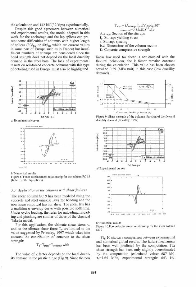
the calculation and 142 kN (32 kips) experimentally. Despite this good agreement between numerical
and experimental results, the model adopted in this work for the anchorage and the lap splices can present some difficulties if columns with higher length of splices (30dbar or 40dbar which are current values in some part of Europe such as in France) but insufficient numbers of stirrups are considered since the bond strength does not depend on the local ductility demand in the steel bars. The lack of experimental results on reinforced concrete columns with this type of detailing used in Europe must also be highlighted.
::: :J~1=L-- -- -: -f1=~:T~ """"'""'' I I ' -30 ·Jl1ii·-·t·-+--r--i-- ---·;.-,-.-~=~-,.,""'.,-,(..-day-cr"""-.--.11
-40 ~ ~ ~ 4 4 4 0 1 2 3 4 5 6
DrlftRallo(%)
al Experimental curves
bl Numerical results Figure 8. Force-displacement relationship for the column FC 15 (failure of the lap splices)
3.3 Application to the columns with shear failures
The shear column SC 9 has been modeled using the concrete and steel uniaxial laws for bending and the non linear empirical law for shear. The shear law has a multilinear envelop curve with possible softening. Under cyclic loading, the rules for unloading, reloading and pinching are similar of those of the classical Takeda model.
For this application, the ultimate shear stress •u and so the ulimate shear force Tu are limited to the value suggested by Priestley, 1997 which takes into account the contribution of concrete to the shear strength:
T u=Tsteel+ T concrete with
The value ofk factor depends on the local ductility demand in the plastic hinge (Fig 9). Since the non
891
Tsteel = (Astirrups·fy.dls).cotg 30° Tconcrete=0.8.k.(fc)O.S .d.b
Astirrups: Section of the stirrups fy: Stirrups yielding stress s: Stirrups spacing b,d: Dimensions of the column section fc: Concrete compressive strength
linear law used for shear is not coupled with the flexural behaviour, the k factor remains constant during the calculation. This value has been chosen equal to 0.29 (MPa unit) in this case (low ductility demand).
13 15
Curvature Ductility Factor µ'I'
Figure 9. Shear strength of the columns function of the flexural ductility demand (Priestley, 1997)
al Experimental curves
Effon t:ra:ic:ba..">1: (ldp•I
bl Numerical results Figure 10.Force-displacement relationship for the shear column SC9
Fig 10 shows a comparison between experimental and numerical global results. The failure mechanism has been well predicted by the computation. The shear strength has been only slightly overestimated by the computation (calculated value: 687 kN•u=l.64 MPa, experimental strength: 643 kN-
i:u=l.54 MPa). These values must be compared to the maximum shear strength of the column SC 10 which is identical to SC 9 column but strengthened with a steel jacket:
calculated value: 1206 kN (272 kips). This value is given for a local strain of 0.35% in the extreme concrete fibre (in compression) experimental value: 1332 kN (300 kips).
4 METHODOLOGY OF ANALYSIS OF THE BEAM-COLUMN JOINTS
4.1 Experimental results
A large series of static and dynamic tests on structural elements and frames has been performed in Buffalo (NCEER) in order to assess the seismic behaviour of the reinforced frame structures built without or with few seismic detailing in the United States (Aycardi, 1992).
Within this experimental campaign, several exterior and interior beam-column assemblages have been tested under horizontal cyclic loading. The tests have shown the external beam-column joints are the most critical and the present paper focused on such an assemblage.
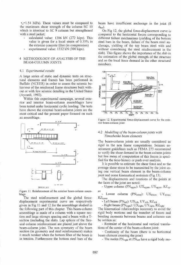
Figure 11. Reinforcement of the exterior beam-column assemblage
The steel reinforcement and the global forcedisplacement experimental curve are respectively given in Fig 11 and 12 for the assemblage studied in the following part of this chapter. This beam-column assemblage is made of a column with a square section and large stirrups spacing and a beam with a Tsection (including the slab). Lap splices of the flexural column reinforcement are placed just above the beam-column joint. The non symmetry of the beam section (in geometry and steel reinforcement) makes it much weaker when the bottom fiber of the beam is in tension. Furthermore the bottom steel bars of the
892
beam have insufficient anchorage in the joint (8 dbar)·
On Fig 12, the global force-displacement curve is compared to the horizontal forces corresponding to different failure mechanisms (yielding of the bottom steel bars in the beam, failure of the beam steel anchorage, yielding of the top beam steel with and without considering the steel reinforcement in the slab). This figure shows the importance of the slab in the estimation of the global strength of the structure and so the local force demand in the other structural members.
1.00
'[ 0.50
~ 0.00 ----·--0
~ -0.5 ----
-1.00
Yo 4Vo SYo
Figure 12. Experimental force-displacement curve for the exterior beam-column joint
4.2 Modelling of the beam-column joints with Timoshenko beam elements
The beam-column joints are usually considered as rigid in the non linear computations. Seismic assessment guidelines such as FEMA 273 recommend to verify the shear demand in the beam column joints but few mean of computation of this forces is specified for the time-history or push over analysis.
It is possible to estimate the shear force and so the average shear stress to be transmitted by the joint using one vertical beam element in the beam-column joint and some kinematical restraints (Fig 13).
The displacements and rotations of the points at the faces of the joint are noted:
- Upper column (PNupper): UXuppm UYuppm RZup-per
- Lower column (PN1ower): UX1owm UY1owm RZ1ower
- Left beam (PN1ett): UX1ett, UY1ett, RZ1ett - Right beam (PNright): UXrighto UYrighto RZright
The kinematical relationships necessary to avoid the rigid body motions and the transfert of forces and bending moments between beams and columns can be written as:
- Restraint of the horizontal and vertical translations of the center of the beam-column joint:
- Continuity of the beam (there is no horizontal beam element crossing the joint)
- The nodes PNright et PN1eft have a rigid body mo-

UYjoint=0.5 (UYright+UYiett)=0.5 (UYupper+UY1ower)
tion (translations et rotation) - The bending moments at the nodes PNright and
PN1ett are transmitted from the beams to the columns only by horizontal shear forces to the points PNupper and PN1ower· This can be insured by the following kinematic relationship
RZrigh1=(UX1ower-UXupper)IHjoint ( =RZ1ett)
Hjoint: Joint height
These kinematical relationships allow to compute the shear force in the vertical beam element representative of the beam-column joint in accordance to the commonly adopted distribution of shear force in the columns and joints (Paulay, 1992 and Fig 13).
The previous non linear law with softening gives the possibility to check the brittle shear mechanism of the beam-column joint.
v,
Exterior joint ReplU'tition of bending nwment and shear force in the columns andjoilll
Figure 13. Modelling of the beam-column joint with Timoshenko beam finite element
It must also be noticed such modelling allows to check the anchorages of the steel bars of the beam into the joint and the lap splices in the columns since such verifications are performed in the plastic hinges.
4.3 Application
The exterior beam-column assemblage described in the chapter 4.1 has been analysed using the previous modeling approach with a non linear shear law for the joint and the uniaxial law for the anchorage of the lower steel bars of the beam and the lap splices of the upper column.
An horizontal loading controlled in displacement has been applied with a cyclic history. It must be noticed the same vertical loading than during the tests has been applied onto the column. The vertical load N depended directly on the horizontal reacting force V in the horizontal actuator:
N=5+2V (kips) The joint shear strength 'tj has been chosen in ac
cordance to FEMA 273: T•=A·r·.Jfc
It comes for the present assemblage a maximum joint shear stress equal to 6.22 MPa. (y=15).
For the flexural steel anchorage and lap splices, the maximum bond strength has been chosen equal to 5 MPa.
The Figures 14 and 15 show respectively the global force-displacement curve and the deformed mesh for the positive and negative maximum displacements.
Figure 14. Numerical force-displacement curve for the exterior beam-column joint
893
Figure 15. Calculated deformed mesh of the exterior beamcolumn joint under positive and negative loading
Under the positive loading, the anchorage of the bottom steel in the beam is critical in both the computation and the experiment.
Under negative loading, higher value of force has been reached since all the steel reinforcement of the upper slab has been considered for the beam section. The numerical model has shown a brittle failure in the beam-column joint since the maximum shear stress has been reached in the beam element representative of the joint. During the experiment, the flexural steel bars of the column failed in tension at the interface between the lower column and the joint. The computation has also slightly overestimated the global strength of the assemblage.
5 CONCLUSIONS
The present paper gives some general consideration about the application of non linear modeling to the seismic assessment of existing reinforced concrete buildings.
The modeling approach is based on non linear Timoshenko beam elements and uniaxial constitutive laws which can take into account some details of construction such as the anchorages, lap splices, confinement, etc ... A methodology of verification of the beam-column joint has also been given. The application of these non linear models to several experimental results has shown their capabilities to catch some brittle failure modes although some limitation has been highlighted.
The present work emphasizes the necessity of experimental results for the validation of such numerical approach and their acceptance for the assessment of existing facilities. The lack of experimental results on structural members with detailing used in Europe must also be remarked.
Finally, as it is done for the masonry infilled frames (Combescure, 2000a & 2000b), the semiglobal modeling level can be completed by using non linear refined finite elements for the identification of the parameters of the fibre model constitutive laws (shear strength, for example).
ACKNOWLEDGEMENT The present work was performed with the support of the French Institute for Nuclear Protection and Safety (IPSN). The authors would like also to acknowledge P. Pegon from ELSA Laboratory of JRC Ispra (Italy) for his (technical and moral) support in the implementation of the numerical models.
894
REFERENCES
Aboutaha, R .. 1996. Seismic retrofit of non-ductile reinforced concrete columns using rectangular steel jackets. PhD Thesi dissertation, Austin University.
Aycardi L.E., Mander J.B. & Reinhom A.M. 1992. Seismic Resistance of Reinforced Concrete Frame Structures Designed Only for Gravity Loads : Part II-Experimental Performance of Subassemblages. Technical Report NCEER-92-0028, NCEER, State University of New York, Buffalo.
Combescure P. & Pegon P. 2000a. Application of the local to global approach to the study of infilled frame structures under seismic loading. 12'" World Conference on Earthquake Engineering, Auckland.
Combescure P. & Pegon P. 2000b. Application of the local to global approach to the study of infilled frame structures under seismic loading. Nuclear Engineering and Design, J 96 J 7-40, Elsevier Editor.
ECS. 1998. Eurocode 8. Design provisions for earthquake resistance of structures- Part 1-3 : General rules - Specific rules for various materials and elements. CEN.
Eligehausen R. & Balazs G.L. 1993. Bond and detailing. In Bulletin d'Jnformation CEB N°217, Comite Eurolnternational du Beton.
FEMA. 1997. FEMA 273-NEHRP Guidelines for the Seismic Rehabilitation of Buildings. FEDERAL Emergency Management Agency.
Guedes, J. 1997. Seismic behaviour of reinforced concrete bridges. Modelling, numerical analysis and experimental assessment. PhD Thesi Dissertation. Porto University.
Menegotto M. & Pinto P. 1973. Method of analysis for cyclically loaded reinforced concrete plane frames including changes in geometry and non-elastic behaviour of elements under combined normal force and bending. 1ABSE Symposium on resistance and ultimate deformability of structures acted on by well-defined repeated loads, Lisbon.
Monti, G. 2000. Consistent insertion of bond-slip into beam fiber elements for biaxial bending. 12'" World Conference on Earthquake Engineering, Auckland.
Paulay, T. & Priestley, N. 1992. Seismic design of reinforced concrete and masonry buildings. Wiley Interscience.
Pegon, P. 1993. A Timoshenko simple beam element in Castem 2000. JRC Technical Note N°1.93.05, Ispra. European Commission.
Priestley, N. 1997. Displacement based seismic assessment of reinforced concrete buildings. Journal of Earthquake Engineering, Vol I, N°1, 157-192. Imperial College Press.
Xiao Y. & Ma R. 1997. Seismic retrofit of RC circular columns using prefabricated composite jacketing. Journal of Structural Engineering, Vol. 123, N°10, ASCE ..