Embed Size (px)
Citation preview
BENCHMARK TESTING FORSPACEBORNE GLOBAL POSITIONING
SYSTEM RECEIVERS
Greg N. Holt∗
The University of Texas at AustinAustin, TX
E. Glenn Lightsey†
The University of Texas at AustinAustin, TX
and Oliver Montenbruck‡
DLR German Space Operations CenterOberpfaffenhofen, Germany
The use of spaceborne Global Positioning System (GPS) receivers has increased asspace mission designers seek to obtain high quality navigation and science data. Receiverselection is often complicated, however, by specific mission requirements and non-uniformmanufacturer testing standards. A uniform set of benchmark tests was defined by whichreceivers may be independently evaluated for a variety of space mission requirements.In addition, a subset of these tests was performed and documented. The receivers usedfor this study included the Mitel Architect, Zarlink Orion, Goddard Space Flight CenterPiVoT, Jet Propulsion Laboratory BlackJack, Trimble Force-19, Johnson Space CenterShip Channel, Surrey SGR-20, Asthech G12, and NovAtel Millenium. This study soughtto characterize the raw measurement accuracy and tracking loop errors by using a GPSconstellation simulator. To this end, a differencing technique was introduced which pre-serves systematic errors in the solution. The results of this study showed correctablesystematic errors in two of the receivers which were tested. Raw measurement accuracywas also verified for all the tested receiver models.
INTRODUCTION
IN recent years, the Global Positioning System(GPS) has become a common sensor for spacecraft
navigation and, in some cases, attitude determination.The primary means for evaluating candidate GPS re-ceivers for mission requirements has traditionally beenthrough the use of manufacturer supplied documen-tation, such as performance specifications. However,these receiver performance results are not standardand may not be reproducible. Also, receivers are rarelytested under similar conditions, so that their resultsmay be compared. As more mission planners turn toGPS to meet their navigation requirements, the needfor an independent evaluation of receiver performancebecomes apparent.
This study defines a standard set of tests that maybe used to characterize spaceborne GPS receivers.These tests provide mission planners with importantinformation on the inherent accuracy and trackingloop performance of GPS receivers that may be con-sidered for use on their spacecraft. For this study, a
∗AIAA Student Member (SS), Doctoral Student†AIAA Senior Member (SH), Assistant Professor‡Head GPS Technology & Navigation Group
subset of tests was carried out on a group of nine GPSreceivers. These results are documented and discussed.
Previous studies in this area include Montenbruck& Holt1 and Williams et al.2 Both of these papersdiscuss a similar test regimen on a single receiver de-sign. This study expands substantially on the previouswork by sampling a large number of receiver designsand directly comparing the results.
Receiver performance may be defined on many lev-els, most obviously the final processed navigation solu-tion. This solution, however, is heavily dependent onthe estimation and filtering of the raw measurementsand will vary by application. More fundamentally,the receiver performance may be characterized by rawmeasurement accuracy and systematic tracking looperrors. These low-level performance measurements arecommon to the entire GPS architecture and are the fo-cus of this study. Any navigation algorithm written fora particular application will be fundamentally limitedby the accuracy of the raw measurements from the re-ceiver. In addition, evaluating the raw measurementperformance is useful to understand and optimize thelow-level receiver software.
In order to provide full insight into the characteris-tics of the tracking loops and measurement collection,
1
American Institute of Aeronautics and Astronautics
AIAA Guidance, Navigation, and Control Conference and Exhibit11-14 August 2003, Austin, Texas
AIAA 2003-5666
Copyright © 2003 by Greg Holt. Published by the American Institute of Aeronautics and Astronautics, Inc., with permission.

all errors must be preserved, isolated, and reported inthe analysis. For this reason it is necessary to performthe raw measurement and tracking loop evaluations ona GPS constellation simulator. Although a stationaryoutdoor antenna is much less expensive and more ac-cessible for most testers, it has several drawbacks whencompared to a simulator. The constellation simulatoris able to provide a realistic high Doppler environmentwhich affects the raw measurements in space but is notseen in a ground test. The simulator is also able to pro-vide an environment free from external errors such assatellite ephemeris errors, satellite clock errors, iono-sphere and troposphere effects, and multipath. Anyerrors seen in the simulation tests are primarily due tothe receiver hardware and tracking loops. Simulatorsare also able to create repeatable test conditions whichlead to verifiable results.
BENCHMARK TESTING ANDSCOPE
GPS receiver benchmark testing is a wide field withmany aspects and procedures. This section gives anoverview of the different types of benchmark testing,then defines the subset of tests actually performed forthis analysis.
Test Types
Each of the following test types is a part of theoverall benchmark evaluation of a spaceborne GPS re-ceiver. These tests are summarized in the test matrixof Figure 1 with priorities assigned based on the rele-vance of the tests for a given application.
Static
A static test is simple to perform and gives basicinformation on receiver performance. Static tests maybe performed with live-sky measurements or in simu-lation (with and without external errors). If live-skyand simulated data is compared, receiver error toler-ance may be observed. This test does not simulate thehigh Doppler environment of space flight, however, sothe tracking loop performance will not be comparableto that of an orbital environment.
On-Orbit
Short of actual space flight test opportunities (e.g.,sounding rockets), an on-orbit test is only available insimulation. A spaceborne GPS system, however, willspend most of its operational life performing on-orbitnavigation. This high Doppler environment will affectthe receiver tracking loops differently than a static sce-nario. For this reason, an on-orbit evaluation is a highpriority test when validating or selecting a receiverdesign. On-orbit tests may be used with environ-mental and ephemeris errors disabled to evaluate rawmeasurement accuracy and tracking loop performance.These simulations may be conducted for various orbitand mission types. The polar, LEO (Low Earth Orbit)
� � � � � � � � � � � �
� � � �
� � � � � � �
� � � � �
�� � �� �
�
� � � � � � � � � � � �
� � � � � � � � � � � � �
� � � � � � � � � �
� � � � � � � � � � �� � � � � � � � � �� � � � � � � � � � � � � � � � �� � � � � � � � � � � � � � �� � � � � � � � � � �� � � � � � � � � � � � � � � � � �� � � � � � � � � � � � � � � � � � �
���� �
�� ������
�� �
�����
��
��� ��
��
����!�� ���
"��"
! �
����� ���������
�� �
����
��
��"
��
�����
��
����� ��
��
#�"
��
�$��% �
�&���� ��
��
'��
��
(��
�)���� �
"! �������*��
���
���� ��
���������
Fig. 1 Benchmark Test Matrix
on-orbit subset of tests was selected and performed forthis study. The polar test produces a high variationof satellite visibility and Doppler shifts for evaluatingraw measurement accuracy and tracking loop perfor-mance.
Pseudolite
Pseudolites (GPS signal transmitters) have gainedinterest for their abilities in close proximity space-craft rendezvous (e.g., near the International SpaceStation). A spaceborne GPS receiver used in thissituation will need special firmware modifications toeffectively receive, process, and utilize these pseudolitesignals. Receivers with this capability may be testedinitially by wiring directly to a pseudolite. In latertest phases, a pseudolite constellation may be used ina variety of noise environments with static and dy-namic antenna motion. More information concerningpseudolites may be found in Stone.3
Orbital Relative Navigation
For receiver applications where relative navigation isanticipated, a simulated orbital test is useful to evalu-ate receiver performance and navigation filter design.In general, two receivers are needed and a real timeloop is established to accomplish the relative naviga-tion. By using both error and error-free scenarios, afilter sensitivity may be estimated and compared withother filter/receiver combinations.
Integrated
Much interest has been expressed in combining aGPS system with other sensors such as an Inertial Nav-igation System (INS) or star tracker to provide bet-ter navigation quality than either sensor could alone.These integrated systems can be tested in simulation,but simulated secondary sensor measurements must beprovided in addition to a GPS simulator in order tostimulate both systems. This test will generally onlybe necessary if anticipated uses of the GPS receiverinclude integrated systems.
Test Matrix
The test matrix for GPS receiver benchmark char-acterization is shown in Figure 1. This matrix showswhich set of tests supply information about which as-
2
American Institute of Aeronautics and Astronautics

pects of receiver performance. Each column of thetest matrix represents a receiver characteristic to beevaluated. Code, carrier, and range rate accuracy arerelated to the raw measurement performance of the re-ceiver. Tracking loop errors are related to the firmwaredesign. Error Sensitivity is evaluated by comparingreceiver performance with and without environmentaland ephemeris errors. The Pseudolite and Integratedcategories are related to the receiver performance inthese specialized environments. Attitude determina-tion from a GPS receiver is related to the carrier phasemeasurement and is covered by that test.
Scope
To completely evaluate the performance of a re-ceiver, the entire test matrix should be considered. Forthis study, however, only a portion was completed astime allowed. In Figure 1 the scope of this projectis highlighted in the overall test matrix. A near po-lar LEO scenario provides useful information aboutthe phase of operation where a spaceborne receiverspends most of its operational lifetime. Even thoughthe simulation is for a polar orbit, these results maybe transferred to other inclinations since a polar orbitwill produce the highest variation of satellite visibilityand Doppler shift and other orbits may be consideredto be less extreme examples of that case.
TEST CONFIGURATIONThe constellation simulator used for this research
is shown in Figure 2(a). It is a Spirent (formerlyGlobal Simulation Systems) model STR4760 and has 2dual-frequency output ports with 16 channels per port.Complete simulator specifications may be found in themanual by Spirent.4 The simulator is controlled by aDigital Electronics Corporation (DEC) Alpha Work-station shown in Figure 2(a). It is manufactured byCompaq, Inc. and uses the Open Virtual Memory Sys-tem (Open VMS) operating system.
A complete description of the orbital simulation sce-nario is found in Holt.5 The scenario is summarizedbelow.• Semi-major Axis: 6823.0 km• Eccentricity: 0.001• Inclination: 87o
• Longitude of Ascending Node: 135o
• Argument of Perigee: 0o
• Mean Anomaly: 0o
• Epoch: 6 Nov 2001 00:00.00 GPS, 5 Nov 200123:59:57 UTC• GPS Week: 1139, 172800 secondsThe orbital simulation is for a low earth satellite ina near polar orbit. The almanac file used to gener-ate this scenario was YUMA1139. All environmentaland ephemeris errors were eliminated from this sce-nario. These include ionosphere, troposphere, multi-path, satellite clock, and satellite ephemeris errors.
a) GSSi GPS Constellation Sim-ulator and DEC Alpha OpenVMS Workstation
+ � � � � � � � �
� � � � � �
� � � � � � � � � � � �� � � � � �
� � � � � �
) � � �� � � � � � � � �� �
, - - ., / 0 ., 1 . 1
b) Test Setup
Fig. 2 Laboratory Simulation Equipment
For this experiment the components were set up inthe configuration of Figure 2(b). The standard orbitaltest was initiated on the simulator during each datarun. The signal was sent through a preamplifier andthen to the receiver under evaluation, with the signalgain adjusted for the operating level of each individualreceiver. The data output stream was collected on aPersonal Computer (PC) via a serial connection. Eachreceiver was tested for two hours in this environment.This time span was sufficient to give multiple horizonto horizon GPS visibility arcs for differencing.
Each receiver in the test had unique hardware andsoftware components which affected its performance.Most receivers had 12 channels, but some had as fewas six. For tracking loops, different combinations ofphase lock loops (PLL) and frequency lock loops (FLL)were used. Most receivers use a temperature controlledcrystal oscillator (TCXO), but the Blackjack uses asteered voltage controlled crystal oscillator (VCXO).Several receivers also had multiple Radio Frequency(RF) ports, front ends, and correlators for multipleantenna attitude determination.
Architect
The Architect receiver was manufactured by MitelSemiconductor (presently Zarlink Semiconductor). Itis based on the Plessey chipset using the ARM32 mi-croprocessor and is user programmable with availablesource code. The Architect receiver was originallydesigned for terrestrial applications as a 12-channel,single frequency, single RF design. Source code mod-ifications by GSOC have made the receiver capableof outputting code, carrier, Doppler offset, carriersmoothed code, and carrier derived range-rate. Thissource code has internal time tag synchronization tointeger seconds on GPS Time when position fixing.The modified firmware uses a second order FLL-aidedPLL for its tracking loop. The receiver hardware in-
3
American Institute of Aeronautics and Astronautics

cludes a TCXO and GP2021 correlator. The Architecthas no space flight history as it was designed only asa development tool for GPS receiver research. Com-plete documentation for the Architect receiver may befound in the manual by Mitel.6
Orion
The Orion receiver is based on a published designby Zarlink using the Plessey chipset and produced byDeutsches Zentrum fur Luft-und Raumfahrt (DLR).The test model was built at the German Space Opera-tions Center (GSOC) and the source code was refinedat The University of Texas at Austin Center for SpaceResearch. Like the Architect, the Orion receiver wasoriginally designed for terrestrial applications as a sin-gle frequency, 12 channel, single RF design. DLRsource code modifications have made the receiver capa-ble of outputting code, carrier, Doppler offset, carrier-smoothed code, and carrier-derived range rate mea-surements. This source code has internal time tagsynchronization to integer seconds based on GPS Timewhen position fixing. The DLR firmware used in thistest uses a second order FLL-aided PLL for its track-ing loop. The receiver hardware is nearly identicalto the Mitel Architect, although the board layout isdifferent. Differences include a real-time clock andnon-volatile memory. The Orion receiver has flown inspace aboard the student-designed experimental PC-Sat with preliminarily good results.7 Detailed Orionreceiver descriptions may be found in the technical re-port by Montenbruck, et. al.8
PiVoT
The PiVoT (Position-Velocity-Time) receiver is pro-duced by National Aeronautics and Space Adminis-tration’s (NASA) Goddard Space Flight Center and isbased on the GPS Builder architecture under a Linuxenvironment and Plessey chipset. The PiVoT receiveris a single frequency design capable of outputting codeand range rate measurements. It has four RF portsand two front end/correlators for planned attitude de-termination capability. The version that was testeddid not have internal time tag synchronization to inte-ger GPS seconds. A TCXO is used in the PiVoT. Thesource code was available and appeared to use a 2nd-order FLL tracking loop. The PiVoT receiver has nospace flight history yet, as it was originally designedas a development tool for spaceborne GPS research.
BlackJack
The BlackJack receiver is produced by NASA’sJet Propulsion Laboratory (JPL), based on the Tur-boRogue design. The test model was the ICESat(Ice, Cloud, and Land Elevation Satellite) Engineer-ing Model on loan from NASA’s Goddard Space FlightCenter. The BlackJack receiver is a dual frequency,single RF design capable of outputting code and car-rier phase measurements. The tests from this study
show code accuracy much better than normal CoarseAcquisition (C/A) code, so Precise (P) code or carriersmoothing of the C/A code measurement is assumed.It uses a steered VCXO to take code and carrier mea-surements, but does not internally correct time tags tointeger GPS seconds. The firmware and tracking loopsare proprietary to JPL, but there is a 10 second av-eraging period used to smooth the raw measurements.In addition, the BlackJack can track the Precise CodeGPS signal even in the presence of anti-spoofing. In-cluding the earlier TurboRogue receiver design theBlackJack has an extensive space flight history, withfavorable results reported during use on Gravity Re-covery and Climate Experiment (GRACE), Challeng-ing Minisatellite Payload (CHAMP), Student NitrousOxide Explorer (SNOE), Shuttle Radar TopographyMission (SRTM), and Ocean Surface Topography Ex-periment (TOPEX/Poseidon).
Force-19
The Force-19 receiver is produced by Trimble Navi-gation, Inc. It was modified by NASA Goddard SpaceFlight Center and Honeywell for use in the Space In-tegrated GPS/Internal Navigation (SIGI) sensor sys-tem. The test model is provided by NASA’s JohnsonSpace Center (JSC) . The Force-19 receiver is a sin-gle frequency design capable of outputting code andrange rate measurements. Based on the accuracies ob-served in this test, it is assumed these measurementsare carrier smoothed. It has four RF ports for atti-tude determination capability. The version tested didnot have internal time tag synchronization to integerGPS seconds. A TCXO is used in the Force-19. TheForce-19 receiver is currently in operation aboard theInternational Space Station (ISS) as part of the SIGIsensor system.
Ship Channel
The Ship Channel receiver was designed and cre-ated at JSC as a dual RF receiver for navigation andheading estimation in the Houston ship channel. It isbased on the same chipset as the Mitel Architect andZarlink Orion receivers. The receiver is a 12 channelL1 only receiver and was tested with the same DLRsource code as the Architect and Orion receivers. Thereceiver hardware is nearly identical to the Mitel Ar-chitect, with the main difference that the Ship Channelis dual RF capable.
SGR-20
The SGR-20 receiver is produced by Surrey Satel-lite Technology Ltd. It is a 4 RF, 24 channel singlefrequency (L1) receiver. The receiver is space capableand has flown in space on the UoSat-12 and TMSatmissions. Like other receivers in this study, the SGR-20 is also based on the Mitel chipset and the 2021 cor-relator. The tested model output code phase, accumu-lated carrier cycles, instantaneous phase, and shifted
4
American Institute of Aeronautics and Astronautics

a) Architect b) Orion c) PiVoT
d) BlackJack e) Force-19 f) ShipChannel
g) SGR-20 h) Ashtech i) NovAtel
Fig. 3 GPS Receiver Test Sample
frequency. The code, carrier phase, and Doppler mea-surements had to be derived from the output of theSGR-20. Researchers at NASA/JSC had created apost-processing program for carrying out this opera-tion.
Ashtech
The Ashtech G12 receiver is produced by ThalesNavigation. The G12-HDMA OEM board was testedin this study. It is a single RF front-end receiver with12 channels. The receiver outputs pseudorange, phaseand Doppler at up to a 2 Hz rate. This receiver willbe used in the Mini-AERCam satellite and has soft-ware modifications for space applications. All trackingloops and navigation algorithms are proprietary andcould not be modified for this study.
NovAtel
The Millennium receiver is produced by NovAtelInc. It is a 12 channel L1 and L2 GPS receiver.The receiver provides pseudorange, phase and Dopplermeasurements at both the L1 and L2 frequencies.The receiver is capable of generating the full P-codepseudorange measurement through proprietary cross-correlation techniques. A design feature for this re-ceiver is NovAtel’s patented Narrow Correlator Tech-nology. The technology allows the receiver to trackpseudorange signals at a small chip width and therebyreduce the effects of multipath. All tracking loops andnavigation algorithms are proprietary and could notbe modified for this study.
ANALYSISThe analysis for this research is designed to produce
performance results for low-level receiver measure-ments. Specifically, the analysis seeks to isolate rawmeasurement accuracy and systematic tracking looperrors. In a GPS measurement, however, the dominantfeatures are the geometric quantities and oscillator er-rors. This research uses the technique of interchanneldifferencing to remove these errors. While Kaplan9
mentions how this method has been used many timesin relative positioning, its use in receiver performanceanalysis is a new development. In previous studiesof raw measurement accuracy, curve fitting has beenused to remove these errors.10 While curve-fittingmethod does show the “white-noise” characteristics ofthe measurement, it has the disadvantage of maskingany systematic errors in the receiver. These errorscan identify otherwise undetected dynamic filter prob-lems. By using differencing instead of curve-fitting,this study seeks to remove only the geometric and os-cillator dependent errors and preserve the white-noiseand systematic errors of the receiver. To effectivelyuse this methodology, certain assumptions were made.
Assumptions
Some assumptions are made in the analysis to sim-plify the tests and processing. The main assumptionconcerns the reference truth measurements from theGPS constellation simulator. In a perfect test, the sig-nal that is generated by the simulator is exactly whatis output in the reference file. Since this is never en-tirely true, the results of the measurement differencingwill actually give a combination of error from the re-ceiver channels and the simulator. It is assumed forthis procedure that the simulator error is negligiblecompared to the receiver error.
In addition, simulator truth estimates are collectedat 1 second intervals and interpolated for receiverswhich do not output measurements with integer timetags. It is assumed that interpolation errors are negli-gible with respect to the measurements under analysis.To validate this, the simulated orbit is considered.For this scenario, the mean motion is approximately 1mrad/s with accelerations ∼8 m/s2, acceleration rates∼20 mm/s3, and fourth-order rates ∼0.013 mm/s4.A piecewise cubic Hermite polynomial interpolationmethod was used for which the error is well docu-mented.11 The error is represented as
ε(x) = f(x) − h2m−1(x) = ψm(x)2f (2m)(ξ)(2m)!
(1)
where
ψm(x) =m∏
j=0
(x − xj)
fk(ξ) = kth deriv. of f evaluated at ξ
5
American Institute of Aeronautics and Astronautics
2 � � � � � � � � � , 2 � � � � � � � � � 3
� � � � � � � � � , � � � � � � � � � 3
# � � � � � � � � � � �" � � � � � � � � � � �) � � � � � �
# � � � � � � � � � � �" � � � � � � � � � � � � �� � � � � � � � � � � � 4 � � � � �� � � � � � � � � �
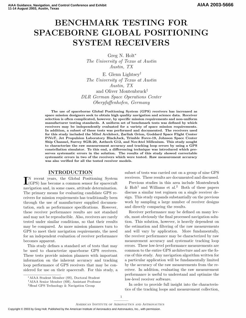
Fig. 4 Measurement Differencing Technique
and m=2 for a cubic Hermite polynomial. By select-ing the nearest time interval so that the interpolationis always less than 1
2 second, the neglected term rep-resents less than 4 × 10⁻⁵ mm, which is many ordersof magnitude smaller than the most accurate carrierphase measurement in the test.
Finally, the simulated signal levels are assumed tobe the actual signal levels experienced in an orbitalenvironment. This is important because tracking loopperformance can be directly affected by low Signal-to-Noise Ratio (SNR). While simulated signal levelswill vary with preamplifier and front-end selection, acommon power level was selected as +8 dB above thenominal GPS signal level. The power increase is de-tailed as follows:• +3 dB: Average antenna gain• +3 dB: GPS signal level higher than published• +2 dB: Thermal noise floor is higher in electronic
simulator than in real environment - needhigher signal level to maintain same SNR
This power level gives SNR readings in most receiverswhich are similar to live-sky tests.
Differencing
Figure 4 shows the analysis technique used for thetests. As stated before, the dominant features ofa receiver measurement are the geometric distance(range) and speed (range rate) between the receiverand GPS satellite. The first step in the data analy-sis is to subtract the simulated, reference geometricquantities from the measurement to give an “errorfrom truth” representation. This is analogous to theclassic GPS “receiver-receiver” single-difference tech-nique except the simulated reference is used as oneof the “receivers.” The quantity that results is freefrom common-mode satellite errors and is dominatedby receiver oscillator drifts and other errors. This pro-cedure is performed for two GPS measurements at atime when their visibility overlaps. Mathematically,the receiver measurement, Measi, consists of range,
ρi, oscillator errors, δT , and other receiver errors, εi.
Measi = ρi + δT + εi (2)
The simulator reference, Refi, consists of range, ρi,and simulator errors , εSi.
Refi = ρi + εSi (3)
These are subtracted to give the single difference, SDi.
SDi = Measi − Refi= δT + εi + εSi (4)
The next step in the analysis is to difference the resultsof the previous operations on two different measure-ments taken at the same time. This removes commonoscillator errors and the remaining quantity representsreceiver and channel specific errors. This is analogousto the classic GPS double-difference except the resultis not a baseline between two receivers but an errormeasurement of a single receiver. This result is thedouble difference, DD1−2.
DD1−2 = SD1 − SD2
= +ε1 − ε2 + εS1 − εS2 (5)
As stated previously, it is assumed the last two terms(simulator errors) are negligible with respect to thefirst two (receiver/channel specific errors). If the errorsare independent and have equal standard deviation,the resulting Root Mean Square (RMS) error will bescaled by
√2 since a double difference was used. For
these independent errors, the receiver intrinsic accu-racy, Acc(ε), is related to the measured error, εmeas,as discussed in Yates:12
Acc(εmeas) =
√√√√ 1n
n∑i=1
ε2i
RMS(εmeas) =
√√√√ 1n
n∑i=1
2ε2i (6)
=√
2Acc(εmeas)
The reported accuracy will be a mean value of all er-rors from both channels and the simulator.
Data Arc Selection
Receiver performance may be characterized in termsof application specific parameters (e.g., multipath)and application independent parameters (e.g., trackingloop error). In order to create a general measure-ment of receiver performance, application independentparameters were evaluated. These parameters are be-lieved to be functions of signal dynamics (Dopplershift) and signal strength (SNR).
To examine receiver performance in a variety of con-ditions, six data arcs were selected from the simulation
6
American Institute of Aeronautics and Astronautics

Table 1 Dynamics and Signal Level Conditions
3, 50
3 ,, 0.
3 /3 1, 63 /3 3, -
, - 5 7 7 7, - / , 7 7, - - 5 7 7, - 0 1 7 7, - . 6 7 7, - - , 7 7
, - 6 / 7 7, / 7 7 7 7, - / 1 7 7, - 5 - 7 7, - - - 7 7, - / 7 7 7
, 71/11-
7 8 ,7 8 37 8 07 8 1, 8 77 8 /
� � * � , � � * � 3� � � � � � � �
9 � � � :� � � � � � �
9 � � � :2 � ( � � � � � �� � � � � � 9 � & :
2 � ( � � � � � � � �� � � � � � � � � � � 9 � ; � :
at standardized time intervals. Since satellite selectionalgorithms vary from receiver to receiver, no guaranteeexists that a receiver will track both satellites duringa particular test interval. With six test intervals, how-ever, most receivers will provide consistent data for atleast some of the intervals. In this entire study, in fact,there were relatively few instances among the nine re-ceivers where a data arc was unusable due to satellitenon-selection.
These data arcs contain a variety of relative dy-namics and signal level conditions. This is importantbecause, as discussed, the raw measurement accuracyis affected by these two factors. The relative dynam-ics conditions come from the differential velocity andacceleration of the two GPS satellites. Satellites withsimilar rise/set profiles will have low relative dynam-ics whereas satellites with differing rise/set profileswill have high relative dynamics. The highest rela-tive dynamics will occur when one SV is just rising(or setting) as the other reaches the peak of its arc.The highest signal levels will occur when both satel-lites have high elevations at the same time. Table 1summarizes the relative dynamics and signal level con-ditions for the standardized test intervals. Figure 5shows sample rise/set profiles for the GPS satellitesvisible in the simulation. The solid red line representsthe local elevation in degrees, while the blue pointsrepresent the signal level in decibels (dB). These plotswere used to select the standard test intervals basedon common satellite visibility and line-of-sight (LOS)acceleration.
−505
10
Sig
[dB
]
0306090
El [
deg]
2
Fig. 5 Sample GPS Satellite Arc for Test Scenario
RESULTSThis section presents the results of the polar, on-
orbit benchmark test. The measured accuracy is dis-cussed for each receiver and sample plots are shown fornotable results. Comprehensive plots for many of thereceivers may be found in Holt.13 Results are listedas “N/A” (Not Available) when the receiver does notoutput a particular type of measurement or did nottrack one of the specified satellites during the run. Allaccuracy assessments are presented together in Table2 at the beginning of the section for convenient com-parison. This table also gives the average results for
each receiver and measurement type. Any processingabnormalities or identifiable sources of error are de-tailed at the beginning of the section for a particularreceiver.
A particularly interesting set of results comes fromthe Architect, Orion, and Ship Channel receivers.These receivers were tested using the same firmwareversion, so all differences in performance should be at-tributable to hardware and board layout. This is aunique opportunity to examine exactly how these fac-tors affect the GPS raw measurement. As the resultswill show, the performance of these three receivers isnearly identical.
In all of the results, it is important to notice anysystematic errors. These errors can be observed by us-ing the differencing technique employed in this study.In several cases (Orion, Force-19), the systematic er-ror results were actually used for debugging to correcttracking loop or time tag errors. In the case of theForce-19 pseudorange performance, the measurementerrors are larger than reported in Table 2 if systematicerrors are included.
Architect
The Mitel Architect was tested with the same sourcecode build as the Zarlink Orion. The code version was‘DLR16707H’ developed by GSOC.8 Any differencesshould therefore be related to board layout or compo-nent disparities. The pseudorange output is smoothingcapable, but for this test only unsmoothed pseudor-ange was considered.
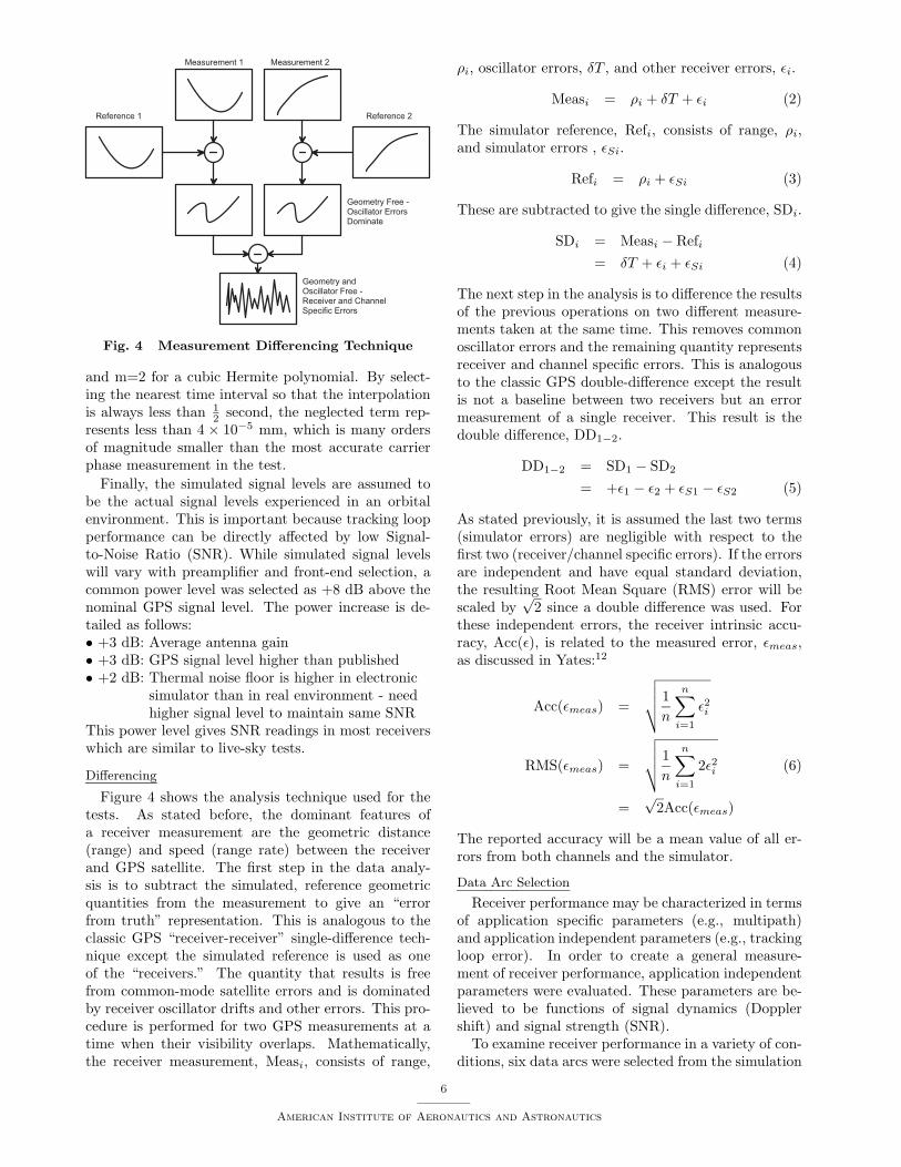
It is clear in Figure 6(a) that the Architect receiverin this test configuration has no systematic errors inpseudorange, carrier phase, or range rate measure-ments. The noise is in an expected range for un-smoothed values of pseudorange and range rate. Sincethe Architect uses the same hardware and code versionas the Orion, it was expected that these two receiverswould produce similar results. When the Architect re-sult is compared with the Orion result in Figure 6(b),this is found to be the case.
Orion
The Zarlink Orion was tested with the same sourcecode build as the Mitel Architect. The code was‘DLR16707H’ developed by GSOC. Any differences inperformance should therefore be related to board lay-out or component disparities. The pseudorange outputis smoothing capable, but for this test only code-basedpseudorange was considered.
In early tests with this receiver, a systematic trendwas found in the carrier phase measurements. Thesame trend was found in the Mitel Architect, so ahardware disparity issue was ruled out. This trendis shown in Figure 6(b), with the original in red andthe corrected in blue. The trend appears to be pro-portional to the LOS accelerations shown in Table 1,a result consistent with the use of the second order
7
American Institute of Aeronautics and Astronautics

Table 2 Receiver Accuracy Assessment Results
PR = Pseudorange, CP = Carrier Phase, RR = Range Rate
� � � � � �� � � � ! � �
� � � � � � � � � � � � � � � � � � � � � � � � � �
� � � � � � �
� � � � � � < � =� � � � � � < � � =� � � � � � < � > � =
� � � � � � < � =� � � � � � < � � =� � � � � � < � > � =
� � � � � � < � =� � � � � � < � � =� � � � � � < � > � =
� � � � � � < � =� � � � � � < � � =� � � � � � < � > � =
� � � � � � < � =� � � � � � < � � =� � � � � � < � > � =
� � � � � � < � =� � � � � � < � � =� � � � � � < � > � =
� � � � � � < � =� � � � � < � � =� � � � � � < � > � =
7 8 1 5 - -7 8 1 3 6 07 8 , 5 , 5
7 8 1 , 1 0, 8 7 / 1 77 8 , 5 5 7
7 8 1 6 6 1, 8 7 . 1 17 8 , 6 . ,
7 8 1 7 3 1, 8 . 5 - /7 8 , 6 , 3
7 8 / 1 . 7, 8 - - . -7 8 , 5 - 0
7 8 / 1 5 3, 8 6 . 6 17 8 , 6 0 5
7 8 1 , 1 0, 8 0 5 6 /7 8 , 5 / 1
3 � 3 /
, 5 � 3 1
0 � , 6
3 , � 3 /
, 0 � 3 3
. � , -
" � � � � �
��������� ��!"
7 8 , 6 6 07 8 6 7 0 0? 7 8 7 7 ,
7 8 , 7 3 67 8 5 3 3 -? 7 8 7 7 ,
7 8 , 0 3 07 8 5 , 7 6? 7 8 7 7 ,
7 8 , 6 0 17 8 1 6 3 5? 7 8 7 7 ,
7 8 , . 7 .7 8 . 0 / 7? 7 8 7 7 ,
7 8 , 3 5 37 8 3 / 0 0? 7 8 7 7 ,
7 8 , 0 / ,7 8 6 0 6 7* > �
, 8 7 0 . /* > �
7 8 3 5 7 7
, 8 , 3 . -* > �
7 8 3 7 1 -
, 8 6 7 7 1* > �
7 8 5 0 / ,
* > �* > �* > �
, 8 3 , - 1* > �
7 8 5 7 - 5
, 8 3 3 3 1* > �
7 8 3 - 1 1
, 8 3 3 , 7* > �
7 8 0 , 6 7
7 8 1 3 6 /7 8 1 0 3 07 8 , 5 7 -
7 8 1 7 0 -7 8 1 3 3 -7 8 , 0 / 3
7 8 1 7 , 6, 8 7 / 1 17 8 , 5 , 1
7 8 1 , 0 ,, 8 , 6 . .7 8 , 6 3 .
7 8 / 1 / ., 8 , / . 57 8 , 5 . 1
7 8 1 3 1 -, 8 3 , , 37 8 , 5 . .
7 8 1 , 3 ,, 8 7 / 0 ,7 8 , 5 5 6
7 8 7 , 6 ,? 3 8 6 1 -7 8 7 , , 7
7 8 7 0 3 5? 3 8 - , -7 8 7 , , .
7 8 7 , 5 6? 3 8 1 3 07 8 7 , 3 5
7 8 7 , 7 ,? 0 8 3 6 77 8 7 , 0 /
7 8 7 , 7 7? 0 8 , 7 37 8 7 , 0 3
7 8 7 , 3 1? 0 8 0 1 17 8 7 , 5 5
7 8 7 , 6 /* > �
7 8 7 , 3 -
� � � � � �� � � � ! � �
� � � � � � � � 4 � �
# � � $ � % � &
7 8 / , 5 6, 8 5 0 0 -7 8 , 7 6 7
* > �* > �* > �
* > �* > �* > �
7 8 / 3 5 53 8 , , . 77 8 , , 0 .
* > �* > �* > �
* > �* > �* > �
7 8 / , 1 5, 8 - - 5 17 8 , 7 1 0
# ' � � � (
* > �* > �* > �
* > �* > �* > �
, 8 0 / , 7* > �
7 8 , / 6 /
* > �* > �* > �
, 8 5 3 5 /* > �
7 8 , 3 3 ,
, 8 0 . 1 0* > �
7 8 , 3 / 0
, 8 0 1 , -* > �
7 8 , 5 6 5
� � � � �
7 8 6 0 1 70 8 , . 3 .7 8 7 / 7 /
7 8 6 3 5 50 8 3 0 - -7 8 7 - / -
7 8 . 0 . 30 8 6 , . -7 8 7 / - .
7 8 6 1 1 .0 8 6 0 , ,7 8 7 / . 1
7 8 . 7 1 30 8 6 6 / 77 8 7 / 1 7
7 8 . 6 1 /0 8 / 5 / 67 8 7 1 1 -
7 8 6 1 5 -0 8 5 - 6 /7 8 7 / - ,
! � � � �
7 8 7 1 1 ,, 8 , 1 - 77 8 7 - 5 6
7 8 , , 3 ,, 8 3 6 . -7 8 7 0 6 1
7 8 , 3 3 ., 8 0 - , 67 8 7 0 6 ,
7 8 , 3 . -, 8 0 6 6 17 8 7 5 3 .
7 8 , 3 , -, 8 0 5 / 77 8 7 6 . 6
7 8 , 3 / 6, 8 5 3 3 /7 8 7 5 7 ,
7 8 , , / 5, 8 0 3 6 07 8 7 5 - 6
PLL found in the Orion. This information was used incode debugging to internally correct the carrier phasemeasurements for acceleration dependence by numer-ically estimating the acceleration. A third order PLLis also under development to remove the acceleration.It is significant to note that only this differencing testcould identify a systematic trend and allow for the rel-atively simple correction.
With the corrected code it is clear that the Orionreceiver in this test configuration has no systematicerrors in pseudorange, carrier phase, or range ratemeasurements. The noise is in an expected rangefor unsmoothed values of pseudorange and range rate.Again, since the Orion uses the same hardware andcode version as the Architect, it was expected thatthese two receivers would produce similar results (seeFigure 6(a)).
PiVoT
The PiVoT receiver was tested with code build“GPS BUILDER A-1.3” provided by the NASA God-dard Space Flight Center.14 It outputs code and rangerate measurements only, not currently possessing thecapability to make carrier phase measurements. Thiscode, therefore, does not use carrier smoothing in thepseudorange or range rate measurements.
In the low relative dynamics case shown in Figure6(c), the results show expected noise values and a smallsystematic “wobble” in the range rate. A high rela-tive dynamics case had an expected increase in noise.
In addition, the pseudorange measurements showed asmall systematic trend at the beginning and end ofthe test interval (corresponding to low SNR levels) andthe range rate measurements show fairly large outliers.These outliers seem to follow a systematic downwardslope for the duration of the test interval. This phe-nomena appears in all the PiVoT tests with high LOSaccelerations.
BlackJack
The BlackJack receiver was tested with the ICE-Sat code build provided by NASA’s Jet PropulsionLaboratory. The BlackJack receiver hardware was theICESat Engineering Model flight spare unit.
The BlackJack receiver had some anomalies whichmade processing difficult. Most of these were fromknown receiver issues which have been addressed byJPL. Most prominent among these was the unexpectedloss of Coarse Acquisition (C/A) code tracking forsome high elevation satellites which causes a subse-quent drift error in the carrier phase measurements.For this study, the lost-lock measurements were notconsidered as they would have severely altered thestatistics of the correct measurements.
Although range-rate measurements are not outputdirectly by the receiver, their accuracy can be esti-mated from the carrier phase measurements by assum-ing a sample rate of 1 Hertz:
AccRR ≈√
2AccCP /dT (7)
For independent sequential errors, the factor of√
2 is
8
American Institute of Aeronautics and Astronautics

introduced by differencing the carrier measurements togive the range rate. Systematic trends will not followthis pattern as the errors are correlated with time.
The BlackJack receiver uses proprietary smoothingalgorithms developed by JPL. These algorithms limitdata output to 10 second intervals, as opposed to the1 second interval used in the other tested receivers.The unsmoothed code and range rate measurementsare not available for output. For low dynamics cases,noise levels are lower than most of the other testedreceivers. This is expected from a highly smoothedsolution. The receiver experienced the previously dis-cussed data dropouts during all the runs. Figure 6(d)shows a high dynamics case where the noise is slightlyhigher as expected. Surprisingly, however, a system-atic drift occurs in the carrier phase measurement.Whether this is a hardware error or a tracking looperror is currently under investigation by JPL.
Force-19
The Force-19 receiver was tested using code build1.10 with attitude code S5.04 supplied by NASA’sJohnson Space Center.
The Force-19 receiver had some notable time taggingdifficulties discovered by this test which hindered dataprocessing. The pseudorange and range rate measure-ments both seemed to be reported with time tags thatwere not consistent with true GPS time. As statedearlier, one important feature of this testing methodis the ability to see systematic drifts that would bemasked by conventional curve fitting. This advantagewas displayed prominently in the Force-19 test. Inall the range rate results, a systematic error was seenwhich was proportional to the LOS acceleration of thetest. Upon closer inspection, a 1/6 second time tagoffset was found relative to GPS time. This would beconsistent with a range rate calculated by a central dif-ference derivative of the carrier phase measurement ata 3 Hertz carrier sample rate. Half of this sample inter-val is 1/6 second, and when the correction is applied tothe time tag the systematic trend is removed as shownin Figure 6(e). Pseudorange observations also seem tohave a time tag error with the same curvature as theline-of-sight velocity but no consistent offset has beenfound as of this writing. Application of the receiverreported clock bias to the time tag does not appear tocorrect this problem.
Although the receiver does not directly output ab-solute carrier phase measurements, the carrier phaseis used to smooth the code measurements and derivethe range rate. From the carrier-derived range rateaccuracy, the carrier phase accuracy can be estimatedby
AccCP ≈ AccRR(dT )/(√
2) (8)
AccCP ≈ AccRR/(3√
2)
where the factor of√
2 comes from the carrier phase
derivative and the factor of 3 comes from the 3 Hertzcarrier sample rate found in the receiver.
Figure 6(e) shows the apparent time tag error dis-covered in this test. The red curve represents theuncorrected measurement, while the blue curve showsthe result with a 1/6 second correction applied. Thetypical results showed expected noise levels for carriersmoothed code and carrier-derived range rate results.The systematic drift is very apparent in the pseudor-ange, with another time tag error as a possible cause.
Ship Channel
The Ship Channel was tested with the same sourcecode as the Zarlink Orion. The code was ‘DLR16707H’developed by GSOC. Any differences should thereforebe related to board layout or component disparities.The pseudorange output is smoothing capable, but forthis test only code-based pseudorange was considered.
It is clear in Figure 6(f) that the Ship Channelreceiver in this test configuration has no systematicerrors in pseudorange, carrier phase, or range ratemeasurements. The noise is in the expected rangefor unsmoothed values of pseudorange and range rate.Since the Ship Channel uses the same hardware andcode version as the Orion, it was expected that thesetwo receivers would produce similar results. When theShip Channel result is compared with the Orion resultin Figure 6(b) this is found to be the case.
SGR-20
The SGR-20 receiver was tested with the code buildsupplied by the manufacturer. It outputs code, carrier,and range rate measurements, although the carrieroutput is anomalous. This code does not use carrieraiding in the pseudorange or range rate measurements.
From inspection of the carrier measurements, it ap-pears that the phase-lock-loop was not operating prop-erly. The code build was proprietary and not available,so no direct examination or repair was possible. Forthis test, therefore, the carrier measurement was notusable. In addition, the receiver had many periods oflost signal lock that hindered the test.
In low relative dynamics cases, the results show ex-pected noise values but large periods of signal loss. Forhigh relative dynamics cases there was an expectedincrease in pseudorange noise. Again, carrier phasemeasurements were unusable for the tests conductedon this receiver.
Ashtech
The Ashtech G12 was tested with proprietary sourcecode provided by the manufacturer. It outputs code,carrier, and range rate measurements at a frequencyof 1 Hz.
For low dynamics cases, noise levels are as expected.It is clear that the Ashtech receiver in this test configu-ration has no systematic errors in pseudorange, carrierphase, or range rate measurements. Figure 6(h) shows
9
American Institute of Aeronautics and Astronautics

174000 174514 175029 175543−10
−5
0
5
10
PR
Err
or [m
]
architect: PRN# 2−28
Acc
= 0
.925
81 m
174000 174514 175029 175543−15−10−5
05
1015
CP
Err
or [m
m]
Acc
= 0
.932
31 m
m
174000 174514 175029 175543−2
−1
0
1
2
Ran
ge−
Rat
e E
rror
[m/s
]
Seconds of GPS Week 1139
Acc
= 0
.140
67 m
/s
a) Architect Low Dynamics
177100 177357 177614 177871−10
−5
0
5
10
PR
Err
or [m
]
orion: PRN# 6−17
Acc
= 0
.884
96 m
177100 177357 177614 177871−10
−5
0
5
10
CP
Err
or [m
m]
Acc
= 1
.565
9 m
m
177100 177357 177614 177871−2
−1
0
1
2
Ran
ge−
Rat
e E
rror
[m/s
]
Seconds of GPS Week 1139
Acc
= 0
.152
39 m
/s
b) Orion Systematic Accelera-
tion Dependence Before (red)and After (blue) Tracking LoopModifications
174000 174514 175029 175543−10
−5
0
5
10
PR
Err
or [m
]
pivot: PRN# 2−28
Acc
= 1
.036
8 m
174000 174514 175029 175543−1
−0.5
0
0.5
1
CP
Err
or [m
m]
Acc
= N
/A
174000 174514 175029 175543−3−2−1
0123
Ran
ge−
Rat
e E
rror
[m/s
]
Seconds of GPS Week 1139
Acc
= 0
.239
95 m
/s
c) PiVoT Low Dynamics
176400 176771 177143 177514−1
−0.5
0
0.5
1
PR
Err
or [m
]
blackjack: PRN# 13−22
Acc
= 0
.160
63 m
176400 176771 177143 177514−3−2−1
0123
CP
Err
or [m
m]
Acc
= 0
.638
01 m
m
176400 176771 177143 177514−1
0
1
Ran
ge−
Rat
e E
rror
[m/s
]
Seconds of GPS Week 1139
Acc
= N
/A
d) BlackJack High Dynamics
174000 174514 175029 175543−1
−0.5
0
0.5
1
PR
Err
or [m
]
force19: PRN# 2−28
Acc
= 0
.340
7 m
174000 174514 175029 175543−1
0
1
CP
Err
or [m
m]
Acc
= N
/A
174000 174514 175029 175543−0.1
0
0.1
Ran
ge−
Rat
e E
rror
[m/s
]
Seconds of GPS Week 1139
Acc
= 0
.011
02 m
/s
e) Force-19 Range Rate Time
Tag Error Without (red) andWith (blue) Time Tag Correc-tion
174000 174514 175029 175543−10−5
05
10
PR
Err
or [m
]
ship channel: PRN# 2−28
Acc
= 0
.814
54 m
174000 174514 175029 175543−15−10−5
05
1015
CP
Err
or [m
m]
Acc
= 1
.433
7 m
m
174000 174514 175029 175543−2
−1
0
1
2
Ran
ge−
Rat
e E
rror
[m/s
]
Seconds of GPS Week 1139
Acc
= 0
.105
02 m
/s
f) Ship Channel Low Dynamics
176500 176843 177186 177529−10−5
05
10
PR
Err
or [m
]
sgr: PRN# 13−22
Acc
= 1
.424
8 m
176500 176843 177186 177529−3−2−1
012x 1011
CP
Err
or [m
m]
Acc
= u
nusa
ble
176500 176843 177186 177529−2
−1
0
1
2
Ran
ge−
Rat
e E
rror
[m/s
]
Seconds of GPS Week 1139
Acc
= 0
.122
07 m
/s
g) SGR-20 High Dynamics
176500 176843 177186 177529−4
−2
0
2
4
PR
Err
or [m
]
ashtech: PRN# 13−22
Acc
= 0
.609
2 m
176500 176843 177186 177529−20
−10
0
10
20
CP
Err
or [m
m]
Acc
= 3
.558
mm
176500 176843 177186 177529−0.5
0
0.5
Ran
ge−
Rat
e E
rror
[m/s
]
Seconds of GPS Week 1139
Acc
= 0
.088
982
m/s
h) Ashtech High Dynamics
174000 174514 175029 175543−1
−0.5
0
0.5
1
PR
Err
or [m
]
novatel: PRN# 2−28
Acc
= 0
.099
053
m
174000 174514 175029 175543−10
−5
0
5
10
CP
Err
or [m
m]
Acc
= 1
.197
mm
174000 174514 175029 175543−0.5
0
0.5
Ran
ge−
Rat
e E
rror
[m/s
]
Seconds of GPS Week 1139
Acc
= 0
.074
545
m/s
i) NovAtel Low Dynamics
Fig. 6 Force-19, Ship Channel, Ashtech, and NovAtel Receiver Result
10
American Institute of Aeronautics and Astronautics

a high dynamics case where the noise is slightly higheras expected. The Ashtech range-rate measurementswere the most accurate of any receiver tested, eventhose with P-code and smoothing capabilities.
NovAtel
The NovAtel receiver was tested with proprietarysource code supplied by the manufacturer. It outputscode, carrier, and range rate measurements at a fre-quency of 1 Hz. The receiver is P-code capable, so itwas tested with a P-code included in the simulated sig-nal. The accuracy reflects the expected improvementsfrom this ability.
A low dynamics case is shown in Figure 6(i), wherenoise levels are among the lowest of all tested receivers.This is expected from a P-code capable receiver. It isclear that the NovAtel receiver in this test configura-tion has no systematic errors in pseudorange, carrierphase, or range rate measurements. For high dynam-ics cases the noise is slightly higher as expected. TheNovAtel results were among the best of all receiverstested in this study, with no signal losses or dropoutsencountered during the testing.
CONCLUSIONSAlthough the original motivation for this research
was to allow mission designers to compare receiver per-formance, the utility of the results in enabling receiverdesigners to improve their product’s performance hasalso been demonstrated. The test results and methodspresented in this study have already contributed toimprovements in several receiver designs. Because rawaccuracy and systematic errors can both be observed,the potential for debugging receivers is improved overtraditional RMS noise methods. The simulated highDoppler environment also allows a more realistic evalu-ation of LOS acceleration dependencies. This researchnot only provides receiver designers with an impor-tant debugging tool but also provides mission plannerswith an independent evaluation of raw measurementaccuracy and tracking loop performance. This is asignificant improvement over manufacturer suppliedspecifications that are usually “best-case” results withlittle or no mention of tracking loop performance.
This research focused on the low-level measurementaccuracy of a GPS receiver. The ultimate navigationsolution produced by a system will depend heavily onestimation algorithms and filtering techniques that arenot evaluated here. All of these systems, however,are based on the common raw measurements that areceiver must make to perform navigation. If prob-lems in the raw measurement quality are identifiedand repaired, the ultimate navigation solution will im-prove as well. For example, the Orion and Architectreceiver tests gave carrier phase measurements whichshowed an acceleration dependence. Only a differenc-ing test would preserve this systematic error in theresults. A fairly simple firmware adjustment led to
a large improvement in the raw measurement qual-ity. The Force-19 time tag error is another example ofthe type of raw measurement improvement which thisstudy made possible. Any tracking loop error whichis identified and repaired using these tests will ulti-mately improve the overall navigation ability of theGPS receiver.
It is hoped that this research will increase the knowl-edge and usage of benchmark testing among the GPSdesign community. This study demonstrates that in-dependent evaluations are important for complex em-bedded systems such as GPS receivers. Spacecraftmissions costing millions of dollars can be marginal-ized or rendered ineffective by a poorly performingGPS receiver. The need for independent testing anddebugging will only increase as GPS becomes a stan-dard system for spacecraft navigation. This researchshows that substantive improvements in receiver per-formance can be obtained by accurately testing thereceiver’s measurements. Using these improvements,better spacecraft mission performance can be obtainedwithout significantly increasing the mission cost.
REFERENCES1Montenbruck, O., G. Holt, “Spaceborne GPS Receiver Per-
formance Testing,” Tech. Rep. TN 02-04, DLR, Oberpfaffen-hofen, 2002.
2Williams, J., et. al., “Testing of the ICESat BlackJack GPSReceiver Engineering Model,” Proceedings of ION GPS Confer-ence, Portland, OR, September 2002.
3Stone, J. et. al., “GPS Pseudolite Transceivers and TheirApplications,” Presented at the ION National Technical Meet-ing 99 , January 1999.
4“STR Series Multichannel Satellite Navigation SimulatorsReference Manual,” Tech. Rep. DGP00032AAC, Spirent Com-munications, Ltd., Devon, UK, 2001.
5Holt, G., “GPS Receiver Benchmark Testing,” Tech. rep.,The University Of Texas Center for Space Research, Austin,TX, March 2002.
6“GPS Architect Users Guide,” Tech. Rep. DM4921, MitelSemiconductor, Wiltshire, UK, March 1997.
7Montenbruck, O., et. al., “GPS Operations on the PCsatMicrosatellite,” Proceedings of ION GPS Conference, Portland,OR, September 2002.
8Montenbruck, O., M. Markgraf, and S. Leung, “SpaceAdaptation of the GPS Orion Firmware,” Tech. Rep.DLR/GSOC TN 01-08, Oberpfaffenhofen, November 2001.
9Kaplan, E., ed., Understanding GPS Principles and Appli-cations, Artech House, Boston, 1996.
10Ryan, S., et. al., “DGPS Kinematic Carrier Phase SignalSimulation Analysis in the Velocity Domain,” Proceedings ofION GPS Conference, Kansas City, MO, September 1997.
11Atkinson, K., An Introduction to Numerical Analysis, Wi-ley, New York, 1978.
12Yates, R., D. Goodman, Probability and Stochastic Pro-cesses, John Wiley and Sons, New York, 1999.
13Holt, G., Benchmark Testing for Spaceborne Global Posi-tioning System Receviers, Thesis, The University of Texas atAustin, 2002.
14Cecchini, J., et. al., “SIGI SP Interface Control Documentto Trimble GPS Receiver with Goddard Space Flight CenterAttitude Microprocessor Software,” Tech. Rep. ICD 34204012,Honeywell Sensor and Guidance Products, Clearwater, FL, May1998.
11
American Institute of Aeronautics and Astronautics