Embed Size (px)
Citation preview

twu4UPPER MISSISSIPPI -KASKASKIA -ST. LOUIS BASIN
STEEGER LAKE DAM 4JEFFERSON COUNTY, MISSOURIw
PHASE 1 INSPECTION REPORTNATIONAL DAM SAFETY PROGRAM
,original contains colorplates: All DTIC repro' ct.ions will be ini black andwhite* -
Uited States ArmyCrsof Engineers
.. Sring the Army
.. nSrvng the Nation
St. Louis District
C.3) PREPARED BY: U.S. ARMY ENGINEER DISTRICT, ST. LOUIS_______A Approved for pui~~c reeQk ca
-_L~JFOR: STATE OF MISSOURI Dtstribudton -'~a'EI
14__ NO'ThEMBER 19P.
* 1;' 10 21

BestAvailable
Copy

UNCLASSIFIEDSECURITY CLASSIFICATION OF THIS PAGE (Wen Data Entered)
REPORT DOCUMENTATION PAGE BEFORE COMPLETING FORMt. REPORT NUMBER 2.GOVT ACCESSION No. 3. RECIPIENT'S CATALOG NUMBER
I b-Al 42iL 04. TITLE (and Subtitle) 5. TYPE OF REPORT & PERIOD COVEREDPhase I Dam Inspection ReportNational Dam Safety Program Final t wSteeger Lake Dam (MO 11098) 6- PERFORMING-ORG.-REPOENUMBER
Jefferson County, Missouri7. AUTHOR(.) 8. CONTRACT OR GRANT NUMBER(a)
Horner & Shifrin, Inc.
DACW43-8p-c- 063 /9. PERFORMING ORGANIZATION NAME AND ADDRESS 10. PROGRAM ELEMENT, PRQJECT. TASK
U.S. Army Engineer District, St. Louis AREA&WORKUNIT NUMBERS
Dam Inventory and Inspection Section, LMSED-PD210 Tucker Blvd., North, St. Louis, Mo. 63101
II. CONTROLLING OFFICE NAME AND ADDRESS 12. REPORT DATE- U.S. Army Engineer District, St. Louis ( Novmbe.98 /
Dam Inventory and Inspection Section, LMSED-PD -13. -NUMBER OF PAGES
210 Tucker Blvd., North, St. Louis, Mo. 63101 Approximately 6074. MONITORING AGENCY NAME A-AODRESS(If different from Controlling Office) IS. SECURITY CLASS. (of thi. rirt)
Harold B. /Lockett UNCLASSIFIED
Albert B. /Becker, Jr 15a. DECLASSIFICATION/DOWNGRADINGk, SCHEDULE
16. DISTRIBUTION STATEMEWNT-(of thieRoport)-
) Approved for release; distribution unlimited.
17. DISTRIBUTION STATEMENT (o, abetrct entered In Block 20, If dlfferent from Report)
I National Dam Safety Program. Steeger Lake0 Dam (MO 11P98), Upper Mississippi Kaskaskia -
- St. Louis Basin, Jefferson County, Missouri.
15. SUPPLEMENTARY NOTES Phase I Inspection Report.
.NT
19. KEY WORDS (Continue on revereo side If neceesary and Identify by block number)
Dam Safety, Lake, Dam Inspection, Private Dams
'20, A83TRACT rCatfnue nrooeete &.fif nec'vw*at ad lden tfy by block numbet)_ This report was prepared under the National Program of Inspection of
Non-Federal Dams. This report assesses the general condition of the dam withrespect to safety, based on available data and on visual inspection, todetermine if the dam poses hazards to human life or property.
DD OM J 13 EDITION OF I NOV 65 IS OBSOLETE LJ '.
JA 73 oUNCLASSIFIED
SECURITY CLASSIFICATION OF THIS PAGE (When Data Entered,' -,y

SECURITY CLASSIFICATION OF THIS PAGE(Whaa Date Nntesed)
im
laigSEURT CASIIATO O HI PG(W.n ae nrd

UPPER MISSISSIPPI -KASKASKIA -ST. LOUIS BASIN
STEEGER LAKE DAM
JEFFERSON COUNTY, MISSOURI
MO 11098 aNfN
PHASE 1 INSPECTION REPORTNATIONAL DAM SAFETY PROGRAM
- United States Army
..Serving the Army..Serving the Notion
St. Louis District
PREPARED BY: U.S. ARMY ENGINEER DISTRICT, ST. LOUIS
___ FOR: STATE OF MISSOURI-
NOVEMBER 1980

DE.ARTMENT OF THEAiY- ., NST. LOUIS DISTRICT. CORPS Of ENGINEERS
210 TUCKER BOULEVARD. NORTH- ST. LOUIS. MISSOURI 63101
MIN fi
SUBJECT: Steeger Lake Dam, MO 11098, Phase I Inspection Report
This report presents the results of field inspection and evaluation of the
Steeger Lake Dam. It was prepared under the National Program of Inspection ofNon-Federal Dams.
The owner should initiate immediate action to provide an erosion-free spillway
so that the full existing spillway capacity could be utilized. An erosion-free spillway will pass greater than 50 percent of the Probable Maximum Flood.
Non-implementation of this recommendation will result in an unsafe, non-emergency classification, due to degradation of the spillway crest which
could cause dam failure by floods exceeding 15 percent of the Probable Maximum
Flood.
UVII- _ ~SUBMITTED BY: i ' L)2 M 18
Chief, Engineering Division Date
APPROVED BY:__ __ __ __ __ __ _ _ __ 24M ,R 981Colonel, CE, Dibf ftneer Date
C~ oe
-3u -.oAl,a \i -, .o _ ., __I

STEEGER LAKE DAMN
MI SSOURI INVENTORY NO. 11098
.JEFFERSON COUNTY, MISSOU~RI
PHASE- I INSPECrTON REPORT
NATIONAL Df'!M SAFETY PROGRAM
PREPARED BY:
HORN'ER & SHIFRIN, INC.5200 OAKLAND AVENUE
ST. LOUIS, MISSOURPI 6 311-0
FOR:
U. S. ARMY ENGINEER DISTRICT, ST. LOUIS
CORPS OF ENGGINEERS
-, NOVE4BER 1980
HS-8011

PHASE I REPORT
NATIONAL DAM SAFETY PROGRAM
Name of Dam: Steeger Lake Dam
State Located: Missouri
County Located: Jefferson
Stream: Tributary of Sugar Creek
Date of Inspection: 22 September 1980
Z
" The Steeger Lake Dam was visually inspectec-by engineering personnel of
Homer & Shifrin, Inc., Consulting Engineers, St. Louis, Missonarfr9The
purpose of this inspection was to assess the general condition of the dam with
respect to safety, and, based upon this inspection and available data,
determine if the dam poses a hazard to human life or property.
The followingqsummarizes the findings of the visual inspection and the
results of certain hydrologic/hydraulic investigations performed under the
direction of the inspection team. Based on the visual inspection and the
results of these hydrologic/hydraulic investigations, the present general
condition of the dam is considered to be somewhat less than satisfactory. The
fact that the reservoir has experienced excessive leakage since completion of
the dam does not, in the opinion of the inspection team, reflect adversely on
the general condition of the dam. The following deficiencies were noticed
during the inspection and are cchsidered to have an adverse effect on the
overall safety and future operation of the dam:
1. A small pond (about one-quarter acre) lies just downstream of the
spillway for the Steeger Lake Dam. Spillway releases from Steeger
Lake will be confined to an area between the main dam and the
embankment for the pond through the exit section of the spillway Ioutlet. According to the Owner, this area of the spillway outlet
charnel is to be protected by a concrete liner; however, at the time
of the inspection, the spillway crest and the spillway outlet
charnel, except for some grass, was unprotected. Lack of a durableU
z . ... .

--7 -- _
form of spillway erosion protection will permit significant
S degradation of the spillway crest by lake outflow with erodible
velocities. It will also allow spillway releases to impinge upon the
dam which could result in loss of embankment material by high
velocity spillway flows; a condition that could impair the
structural stability of the dam.
2. Some minor surface erosion that appeared to be due to overland
drainage has occurred across most of the grass covered upstream face
of the dam beginning at a level about 10 feet below the top of the
dam. (Ordinarily, this portion of the dam would be submerged and not
subject to erosion by overland drainage, but would be subject to
erosion by wave action and by fluctuations of the lake level that
cannot be controlled by a vegetative type cover.) Erosion of the
embankment by either overland drainage or by wave action and/or
fluctuations of the lake level can impair the structural stability of
the dam.
According to the criteria set forth in the recommended guidelines, the
magnitude of the spillway design flood for the Steeger Lake Dam, which is
classified as small in size and of high hazard potential, is specified to be a
minimum of one-half the Probable Maximum Flood (PMF). Considering the fact
that a relatively small volume of water is impounded by the dam, that the
flood plain downstream of the dam is fairly broad, and that there are but
three dwellings within the estimated flood damage zone, it is recommended that
the spillway for this dam be designed for one-half the Probable Maximum
Flood. The Probable Maximum Flood (PMF) is the flood that may be expected
from the most severe combination of critical meteorologic and hydrologic
conditions that are reasonably possible in the region.
According to the Owner, since completion of the dam in 1976, the reservoir
has experienced problems with excessive leakage, as indicated by the inability
of the lake to reach the level of the spillway. At the time of the
inspection, the lake level was about 15 feet below the spillway crest.
Judging by a waterline mark across the upstream face of the dam, the lake had
ii -

been for some period of time approximately one foot higher than the observed
_level. The Owner indicated that the highest lake level experienced to date
was probably about three feet higher than the level at the time of the
inspection. For the purpose of the hydrologic/hydraulic investigations
performed for this dam, the level of the lake just prior to the beginning of
the assumed antecedent storms for the Probable Maximum Flood and the one
percent chance (100-year frequency) flood, was assumed to be the elevation of
the observed waterline mark on the face of the dam, or about 13.8 feet below
the spillway crest.
Results of a hydrologic/hydraulic analysis indicated that the spillway is
inadequate to pass lake outflow resulting from a storm of one-half PMF
magnitude without significant degradation by erosion of the spillway crest.
However, the spillway is capable of safely passing lake outflow corresponding
to about 15 percent of the PMF lake inflow. A similar analysis indicated that
-- with the lake surface at the mean annual high water level (the observed
waterline mark), the reservoir is capable of containing the runoff resulting
from the one percent chance (100-year frequency) flood. According to the St.
Louis District, Corps of Engineers, the length of the downstream damage zone,
should failure of the dam occur, is estimated to be three miles. Accordingly,
within the possible damage zone are three dwellings and a warehouse.
A review of available data did not disclose that seeage or stability
analyses of the dam were performed. This is considered a deficiency and
should be rectified.
It is recommended that the Owner take the necessary action sometime in the
near future to correct or control the deficiencies and safety defects reported
herein. Protection of the spillway in order to prevent erosion by lake
outflow should be assignJ a high priority.
Harold B. LockettP. E. Missouri E-4189
/ i-i ",4 -- "[/
Albert B. Becker, Jr.
P. E. Missouri E-9168 /

LLILLI
LjJ
I-A
PHASE 1 ITNSPECTION REPORT
NATIONAL DAM SAFETY PROQR.4
STEEGEIR LAKE DAM - NIN 11098
TAB-LE OF CONTEN'TS
Paragraph No. Title Paqe Nb.
SECTION 1 - PROJECT It FCFATION
1.1 Genera: !-i
1.2 Description of Project 1-1
1.3 Pertinent Data 1-3
SECTION 2 - ENGINEERIP DATA
2.1 Desion 2-1
2.2 Const ruct ion 2-2
2.3 Operation 2-2
2.4 EvaiLtion 2-3
SECTION 3 - VISUAL INPECTION
3.1 Fi ndings 3-1
3.2 Evaluation 3-5
SECTION 4 - OPERATIONAL PROCEDJRES
4.1 Procedures 4-1
4.2 Maintenance of Dam 4-1
4.3 Maintenance of Outlet Operating Facilities 4-1
4.4 Description of Any Warning Systens in Effect 4-1
4.5 Evaluation 4-1
TU
TC-iI

Paraqraoh hb. Title PaneNo
SECTION 5-HYPULI/YmCC
5.1 vgaiuation -f F eatures 5
SECTION 6 -SlTURTfI SABLI
6.1 Evaluation of Sltuctural- Stat- iit-v 6-1
SECTION 7 -ASSES94ENT/RE!EDIAL DISPE~S
7.1t Dan Assessment 7-13
7.2 Remedial fMeasures '
LIST OFF PLATES AflJ Cim-TS
Plate No. Title
1 R-egional Vicinity map
2 Lakce W"atershed map
3 Dam Plan & Profile
=4 Dam Cross-Section
5 Spillwavyrfl rcs-eto
Chart No. Title
=2-1 thrlu 2-3 Engineerty- 'loogic- Renart~ on -,the Stee LaeSie
Missouri Zeological Sirvey, Apr-il 17, 1975
=2-4 and '2- 5 Addencim-i to fthe GeolonicRpr of tha Steegrw ae
Jefferson Caiy iszEnair-mevring Geology
Section, Geology & L&dSur-vey, My 18, 1979
TC-2

APPENDIX A - INSPECTION PHOTOGRAPHS
g No. Title
A-i and A-2 Inspection Photographs
APPENDIX B - HYDROLOGIC AND HYDRAULIC ANALYSES
Page No. Title
8- 1 and B- 2 Hydrologic & Hydraulic Computations
B- 3 thru 8- 6 Computer Input Data
8- 7 thru B-10 Computer Output Date
B-l1 and B-12 Lake Surface Ar , -.tation and Storage Volume;
Summary of Dam Safety Analysis
B-13 thru 8-15 Spillway Capacity Calculations
TC-3

PHASE I INSPECTION REPORT
NATIONAL DAM SAFETY PROGRAM
STEEGER LAKE DAM - MO 11098
SECTION I - PROJECT INFORMATION
i.l GENERAL
a. Authority. The National Dam Inspection Act, Public Law 92-367, dated
8 August 1972, authorized the Secretary of the Army, through the Corps of
Engineers, to initiate a program of safety inspection of dams throughout the
United States. Pursuant to the above, the St. Louis District, Corps of
Engineers, directed that a safety inspection of the Steeger Lake Dam be made.
b. Purpose of Inspection. The purpose of this visual inspection was to
make an assessment of the general condition of the above dam with respect to
safety and, based upon available data and this inspection, determine if the
dam poses a hazard to human life or property.
c. Evaluation Criteria. This evaluation was performed in accordance
with the "Phase I" investigation procedures as prescribed in "Recommended
Cuidelines for Safety Inspection of Dams", Appendix D to "Report to the Chief
of Engineers on the National Program of Inspection of Non-Federal Dams", dated
May 1975.
1.2 DESCRIPTION OF PROJECT
= a. Description of Dam and Appurtenances. The S,eeger Lake Dam is an
earthfill type embankment rising approximately 35 feet above the natural
- streambed at the downstream toe of the embankment. The embankment has an
upstream slope (above the waterli e) of approximately 1v on 3.4h that steepens
- to about lv on 2.5h at an elevation nearly 10 feet below the top of the dam, a
crest width of about 11 feet and a somewhat irregular downstream slope on the
order of lv on 2.4h. The length of the dam is approximately 385 feet and a
road surfaced with gravel traverses the crest of the dam. A plan and profile
==1-1

of the dam is shown on Plate 3 and a cross-section of the darn at about the E
location of the original stream channel is preser ted ou Plate 4. At spillway
crest level, the reservoir impounded by the dam would ocupy approximately 6
acres. At the present level of the lake, which is nearly 15 feet below the
spillway crest, the reservoir occupies approximately 2 acres. The d3m has no
drawdown facility to unwater the lake. An overview photo of the Steeger Lake
Dam is shown following the preface at t. beginning of the report,
The spillway for the dam, an excavatcd earth trapezoidal section, is
located at the right, or south, a r t. A small pond on the order of
one-quarter of an acre is under c , ,n just downstream of the spillway
location. The spillway outlet chan; l, aithough not well defined through the
area downstream of the dam, appears to join the original stream on which the
embankment is constructed, at a point about 100 feet downstream of the toe of
the dam. A profile and cross-section of the spillway channel are shown on
Plate 5.
b. Location. The dam is located on an unnamed tributary of Sugar Creek,
about 0.8 mile southeast of the intersection of Rock Creek Road and StateHighway 30, and approximately 1.0 mile southeast of the Town of High Ridge,Missouri, as shown on the Regional Vicinity Map, Plate 1. The dam is located
within Section 24, Township 43 North, Range 4 East, in Jefferson County.
c. Size Classification. The size classification based on the height of
the dam and storage capacity, is categorized as small (per Table I,
Recommended Guidelines for Safety Inspection of Dams).
d. Hazard Classification. The Steeger Lake Dam, according to the St.
Louis District, Corps of Engineers, has a high hazard potential, meaning that
if the dam should fail, there may be loss of life, serious damage to homes, or
extensive damage to agricultural, industrial and commercial facilities,
important public utilities, main highways, or railroads. The estimated flood
damage zone, should failure of the dam occur, as determined by the St. Louis
District, extends three miles downstream of the dam. Within the possible
damage zone are three dwellings and a warehouse. Those features lying within
1-2

the downstream damage zone as reported by the St. Louis District, Corps of
Engineers, were verified by the inspection team.
e. Ownership. The dam is owned by Mr. and Mrs. ,car A. Steeger. Mr.
and Mrs. Steeger's address is: 3456 Rock Creek Road, H ,h Ridge, Missouri
63049. The Steeger residence is on the property where the dam is located.
f. Purpose of Dam. The original purpose of the dah, was to impound water
for commerical benefit, i.e., fee fishing. However, since the lake has not
filled to the desired level, the reservoir has not, to date, been operated on
a commercial basis.
g. Design and Construction History. The dam was constructed by the
Owner. According to Mrs. Steeger, the dam required about two years to build
and was completed in 1976. Mrs. Steeger also reported that Thomas J. Dean, a
geologist .,ith the Missouri Geological Survey, examined the proposed lake site
prior to construction and made certain recommendations regarding the design
and construction of the dam. A copy of Mr. Dean's report titled "Engineering
Geologic Report on the Steeger Lake Site", dated April 17, 1975, reference
Charts 2-1 through 2-3, is included herewith. An addendum to this report was
also prepared by Mr. Dean following completion of the dam when it was found
that the lake was experiencing excessive leakage. This report titled
"Addendum to the Geologic Report of the Steeger Lake", dated May 18, 1979, is
also included herewith, reference Charts 2-4 and 2-5. Mrs. Steeger also
mentioned that some design assistance was provided in 1975 by the U. S.
Department of Agriculture, Soil Conservation Service (SCS).
h. Normal Operational Procedure. The lake level is unregulated. Lak,
outflow is governed by the capacity of an excavated earth type spillway.
However, according to the Owner, since completion of the dam, the level of the
lake has never reached the spillway crest.
1.3 PERTINENT DATA
( a. Drainage Area. With the exception of some residential type
development along the ridge line of the watershed, the area tributary to the
1-3 1
- - --- ___ - -- -

lake is essentially in a native state covered with timber. The watershed
above the dam amounts to approximately 124 acres. The watershed area is
Outlined on Plate 2.
b. Discharge at Damsite.
(1) Estimated known maximum flood at dam site ... None
(2) Spillway capacity .... 89 cfs (W.S. Elev. 786.3)
c. Elevation (Ft. above MSL). Unless otherwise indicated, the following
elevations were determined by survey and are based on topographic data shown
on the 1954 House Springs, Missouri, Quadrangle Map, 7.5 Minute Series (photo-
revised 1968 and 1974).
(1) Observed pool ... 770.2
(2) Normal pool ... Unknown
(3) .Mean annual high water ... 771.2 (per high waterline mark)
(4) Spillway crest ... 785.0
(5) Maximum experienced pool ... 773.0 2-1
(6) Top of dam ... 790.4 (Min.)
= (7) Effective top of dam ... 786. 3 /
(8) Streambed at centerline of dam ... 758+ (Est.)
(9) Maximum tailwater ... Unknown
(10) Observed tailwater ... None
d. Reservoir.
(1) Length of pool at spillway crest (Elev. 785.0) ... 1,000 ft.
(2) Length of pool at top of dam (Elev. 790.4) ... 1,200 ft.
1/ According to the Owner, the level of the lake has never reached the
elevation of the spillway crest.
2/ Eased on an estimate of lake level as observed by Owner.
3/ Elevation at which lake outflow exceeds permissable velocity.
1-4-Emig

e. Storage.
Ei (1) Spillway crest ... 58 ac. ft.
(2) Top of dam (incremental) ... 39 ac. ft.
f. Reservoir Surface.
(1) Spillway crest ... 6 acres
(2) Top of dam (incremental) ... 2 acres
g. Dam. The height of the dam is defined to be the overall vertical
distance from the lowest point of foundation surface at the downstream toe of
the barrier, to the top of the dam.
(1) Type .... Earthfill
(2) Length ... 385 ft.
(3) Height ... 35 ft.
(4) Top width ... 11 ft.
(5) Side slopes
a. Upstream ... Varies; Iv on 2.5h to lv on 3.4h
b. Downstream ... lv on 2.4h (irregular)
(6) Cutoff ... Core trench Iy
(7) Slope protection
a. Upstream ... Grass
b. Downstream ... Grass
h. Principal S ilway.
(1) Type ... Uncontrolled, excavated earth, trapezoidal section
(2) Location ... Right abutment
(3) Crest elevation ... 785.0
(4) Approach channel ... Lake
(5) Outlet channel ... Trapezoidal section through exit section,
unconfined beyond exit section
1/ Per Owner
1-5

~. Emergency Spillway. No 1ne
j. Lake Orawdown Facility. .. NoneIM
1 I

SECTION 2 - ENGINEERING DATA
2.1 DESIGN
As previously stated, a geologic investigation of the proposed lake site,
reference Charts 2-1 through 2-3, was made in 1975 by Thomas J. Dean, a
geologist with the Missouri Geological Survey. In the report, which is dated
April 17, 1975, Mr. Dean describes the underlying bedrock units and the
surficial soils overlying the bedrock. Mr. Dean points out that both the
limestone, which is present in the streambed near the east property line, and
the sandstone, which is seen outcropping near the upper end of the proposed
lake, are very permeable both vertically and horizontally and will transmit
water rapidly. Mr. Dean states that a thick sequence of clayey soil is
present on the lower valley slopes and valley bottom, and that the soil should
prevent water from reaching the underlying permeable limestone. The report
indicates that a test pit was excavated in the valley bottom near the
streambed and that approximately 6 feet of sandy gravelly clay overlying a
thin gravel bed bearing water was revealed; however, it was believed that the
water in the gravel bed was perched on a clay layer of unknown thickness.
In summary, Mr. Dean reports that there appear to be sufficient amounts of
clay present in the valley walls and bottom to mask the permeable bedrock,
which would allow the site to be geologically feasible for a water impoundment.
In the Dean report, recommendations are made regarding construction of the
core, excavation for borrow material, filling of the streambed upstream of the
dam, and the design of the spillway. With regard to the spillway, Mr. Dean
recommends that, because of the erodibility of the silty clay surface soil, a
pipe type principal spillway be provided to handle the daily flow.
The Owner also reported that some design assistance was provided by the
U. S. Department of Agriculture, Soil Conservation Service (SCS). According
to information provided by Richard L. McMillen, SCS District Conservationist,
St. Louis County (the Jefferson County records are maintained by the St. Louis
County office at Manchester, Missouri), a preliminary design survey of the dam
was made by Leonard Knoernschild, formerly SCS District Conservationist, St.
2-1
7 -
Louis County, in 1975; however, the design survey did not establish the
spillway requirements or specify the embankment proportions. Mr.
Knoernschild, now SCS District Conservationist, Franklin County, was
contacted; however, no details of the design or the site could be recalled.
2.2 CONSTRUCTION
The dam was constructed by the Owner and required approximately two years
to build, having been completed in 1976. According to Mrs. Steeger, a seepage
cutoff trench approximately 5-to-8 feet deep and about 12 feet wide at the
bottom, was excavated across the valley floor along the alignment of the dam.
Mrs. Steeger reported that a seam of gravel was encountered during the
excavation for the trench. Mrs. Steeger indicated that the trench was
backfilled and the embankment constructed with gravelly clay that was obtained
from the area to be occupied by the lake a-, well as the nearby hillsides, that
the borrow material was hauled to the dam in trucks and spread by a tractor,and that compaction of the fill material was obtained by running the tractor,
a John Deere 450, repeatedly over the fill. No tests were made to determine
the degree of compaction obtained.
2.3 OPERATION
The lake level is uncontrolled and, under normal conditions, governed by
the elevation of the crest of the excavated earth type spillway. However,
since completion of contruction, the lake has experienced problems with
excessive leakage, as indicated by the inability of the lake to reach the
level of the spillway. There is no evidence of dam overtopping. According to
Mrs. Steeger, the highest lake level experienced to date raised the lake
surface about 3 feet higher than the observed level at the time of the
inspection, or approximately 12 feet below the spillway crest.
According to Mrs. Steeger, in the spring of 1979 following a heavy
- rainfall, a hole approximately 5 feet deep and 8 feet in diameter, developed
in the bottom of the reservoir just upstream from the lake at a point near the
- old streambed. Subsequently, at the request of the Owner, an investigation of
the reservoir condition was made by Mr. Dean of the Missouri Department of
2-_2-__2_ _ _

Natural Resources, Geology and Land Survey, formerly the Misouri Geological
Survey, and a report was prepared. In the report which is titled "Addendum to
the Geologic Report of the Steeger Lake", reference Charts 2-4 and 2-5, dated
May 18, 1979, Mr. Dean states that the relatively thick plastic clays which
are present in the lake bottom at the dam evidently have some weak spots in
the upstream reaches of the lake, and that these weak points allow the lake to
back up off its clay pad to the point where vertical water loss takes place
into the underlying very permeable bedrock.
In the report, Mr. Dean recommends that the most feasible method of
preventing vertical water loss is to pad the bottom of the lake through the
area not holding water. The report also recommends that a core be excavated
to bedrock in the upper end of the lake to force water from the creek to the
surface and onto the clay pad constructed in the lake bottom.
Mr. Dean also addresses a landslide problem that had developed along the
northeastern side of the lake where a sandstone outcropping exists. The
reason for the slide is presented and recommendations are made to remedy
future slides in the area.
According to Mrs. Steeger, Mr. Dean's recommendations regarding the
construction of a core across the upstream end of the lake and the padding of
the reservoir bottom with approximately 2 feet of clay, were followed.
However, in the year since completion of this work, no appreciable permanent
increase in the level of the lake has been evident.
Mrs. Steeger also reported that an attempt was made to seal the lake
bottom using bentonite. It was reported that approximately 2,000 pounds of
bentonite were distributed by boat over the area of the lake; however,
beneficial results of the bentonite operation were not conclusive.
2.4 EVALUATION
a. Availability. Detailed engineering data for assessing the design of
the dam and spillway were unavailable.
2-3

WE __ _ __ _ _
___b. Adequacy. Available data are inadequate. Seepage and stability
analyses comparable to the requirements of the "Recommended Guidelines forSafety Inspection of Damns" were not avial, which is considered a-dficiency. These seepage and stability analyses should be performed forappropriate loading conditions (including earthquake loads) and made a matterof record.
2-4

SECTION 3 - VISUAL INSPECTION
3.1 FINDINGS
a. General. A visual inspection of the Steeger Lake Dam was made by
Horner & Shifrin engineering personnel, R. E. Sauthoff, Civil Engineer,
H. B. Lockett, Hydrologist, and A. B. Becker, Jr., Civil and Soils Engineer,
on 22 September 1980. An examination of the dam area was also made by an
engineering geologist, Jerry D. Higgins, Ph.D., a consultant retained by
Horner & Shifrin for the purpose of assessing the site geology. Also examined
at the time of the inspection were the areas and features below the dam within
the potential flood damage zone. Photographs of the dam taken at the time of
the inspection are included on pages A-1 and A-2 of Appendix A. The locations
of the photographs taken during the inspection are indicated on Plate 3.
b. Site Geology. The topography at the dam site is moderately rugged,
and relief between the valley bottom at the lake site and the surrounding
drainage divide is about 150 feet. The area is included within the
northeastern part of the Ozark Plateaus Physiographic Province; therefore,
the regional dip of the bedrock is northeastward toward the Illinois Basin.
The lake site itself is located near the axis of the House Springs
Anticline. Although the structure affects the dip of the strata in this area,
the bedrock formations at the dam site still dip to the northeast. Several
faults are associated with the anticlinal structure, although no faulting was
observed at the site. The bedrock at the lake site consists of several
Ordovician- and Mississippian-age limestone, shale, and sandstone formations.
The limestone of the Kimmswick formation is the underlying bedrock at the dam
site and valley bottom. This is overlain by the Maquoketa shale, Bushberg
sandstone, and Fern Glen and Burlington limestones which make up the bedrock
units of the valley walls and uplands.
The Kimmswick is a coarsely crystalline, light grey, massive- to
medium-bedded limestone. It has a distinctive pitted weathering surface, and
nodular chert is scattered in the upper portions of the formation. The
-Kimmswick has typically been extensively solution-weathered and commonly
3-1

contains numerous sirns and solution-enlarged fractures. This weathering has
made the limestone extremely permeable, and it will transmit water readily.
The contact between the weathered bedrock surface and the overlying soils or
residuum is usually irregular. The residual soil, when not modified by
colluvium, is generally quite thin and typically is a reddish-brown,
well-structured, plastic clay with a Unified Soil Classification of CH. Even
though these clays are plastic, their natural perm eabilities are higher than
most clays, especially after drying.
Overlying the Kimmswick is the Maquoketa shale. No unaltered outcrops of
shale were apparent at the site, but weathered shale and plastic clay soils
were located up to about 5 feet above present reservoir level. The Maquoketa,when unweathered, is typically a thin-bedded, silty, calcareous shale. Itweathers to a black, plastic soil, CH in the Unifed Soil Classification
System, that is very impermeable and unstable on steep slopes. Because of itsimpermeable characteristics, seeps and springs are frequently found at the
contact between the Maquoketa and the overlying Bushberg sandstone, andseveral were located around the reservoir perimeter.
The Busi-berg sandstone outcrops on both sides of the reservoir above theMaquoketa and as far up as 15 feet above the top of the embankment. It is amassive, cross-bedded, brown, fine- to coarse-grained porous sandstone that
transmits water readily. Soils derived from the abshberg are sandy, but atthe site include weathered components from the overlying F rn Cen limestone
formation. These soils may be differentiated as light grey to buff, silty orsandy clays that are classified in the ML-CL range in the Unified Soil
Classification System.
The principal bedrock formation underlying the valley sides and uplands is
the Burlington limestone. This formation is a light grey, massively- tomedium-bedded limestone with considerable amounts of nodular and bedded
chert. The residual soils are light red to reddish-brown clays mixed with
chert, stony CH. In general, the clay and chert residuum from the Burlington- are a major component of the soils found on the valley sides and floor.
3-2

Steeger Lake has not been a _suc:essful imsUr-nt and is crEtli filedto less than 25 percent of its dIes-i standing water lev-e.Pi tconstruction, the stream was reorted by the Missouri G logical S-rvey to be
losing flow to the subsurface. Following const,l-M, a seall s* waslocated in the lake area and required sealino wit-h cOna4teo-r .l.
Significant leakage apparently is occurring through te -meabIe Kiw-sw icklimestone which underlies the reservoir. S cwie_- e effluent ws .u-te
downstream in the immediate vicinity of the e t-a~ni t on both sis of the
valley, but as this flow did not seem comparable 'n-_ tohe inflow into treservoir and since the stream bed belo the t was dry, -tch nf fthe
seepage apparently is flowing thrao the bed- Do mre further -treaor into adjacent drainage basins. In addition, c i-rable s~l=uin has
occurred in the aquoketa shale rcsidu NV.ero small slu featurescomprisiJ of plastic clays, sandst.on, and ew tr a-c anare --r -anorth bank of the reservoir. Sxre erosion has also tvooed arman the
eservoir, particularly in the sandy soils frxn Uhe &sterg saMsrWe,
detonstrating the redibility of these soils.
It is apparent that at t heS teo -gr I ake s- -- verse geolonic conditionsare responsible for the lack-o raeroir stor-a. j-wever, these - itions
ct not appear to be affecting th iitv o3n et-- nt.
c. Dam. The visiblheuos te u -r -Gnstr s 0f
the dam (see P.oc , 2 and n - examined be s o dcondition. 1% ctraacking of A"- =-rs
slopes, or unusual settlement a- M- cr s*t w Q da
to survey data obtained durin t rsnect, t i e Crest wa sat-ower, approxiriteIv 0.9 foot, l-f oF t-ue ccn---t the structulre th i S
to the right of the center. - t for- e ton - dam, which rs astlycovered with gravel and small sto i to £ rc in size for roaudy
surfacing, the slopes were, for the t cst part, cm=-ed by grass, a fes c. e d
otter native t.pes of grasses. K--ever, along t-e u---eam face inga level about 10 feet below the dam crest, some cairKr surface er-si an theorder of 6 inche deep and 1 foot wie was notic a c s most o t -te
embarkent. There was no riprap slope prot ction n the upstream fae of the
dam. At the tim of the inspection, the grass or tte downstream face of the
- . _g_' tre- f )- th
dam was up to 3 feet high; on the upstream face, the grass, except near the
top of the dam, had been recently cut and was only several inches high. No
significant erosion of -he embankment was noticed at the junction of the dam
with the abutments, and no seepage was observed at the abutments or the
downstream area adjacent to the dam, or within the examined areas of the
original stream channel for a distance of approximately 230 feet beyond the
toe of the dam. Examination of a soil sample obtained from the downstream
face of the embankment indicated the surficial material to be a stoney,
yellow-brown, silty lean clay (CL) of low-to-medium plasticity.
The excavated earth spillway (see Photo 4) at the right, or south,
abutment was examined and found to be in sound condition without evidence ofsignificant erosion, although the outlet channel (see 0hoto 5), except for a
portion of the exit section, was without a protective grass cover. The
remains of a tree were present in the spillway channel at a point just
downstream of the exit section.
A small pond (see Photo 6) on the order of one-quarter of an acre in
surface area, that is impounded by an earthen dam approximately 9 feet high on
the north side, lies just downstream of the spillway outlet. The pond is
under construction, but the Owner mentioned that it is expected to be
completed this year. According to the Owner, the pond is to be used for
raising catfish. The Owner indicated that the exit section of the s, illway
outlet channel is to be lined with concrete in order to prevent erosion of the
dam as wall as the embankment of the pond; however, the extent of the
protection had not yet been decided. The spillway channel downstream of the
dam was indistinguishable, but probably will join the original stream channel
at a point approximately 100 feet downstream of the toe of the dam.
d. Appurtenant Structures. No appurtenant structures were observed 9t
this dam site.
e. Downstream Channel. Except at roadway crossing, the channel
downstream of the dam within the estimated flood damage zone is unimproved.
The section is irregular and for the most part lined with trees. The stream
joins Sugar Creek approximately 0.4 mile downstream of the dam; Sugar Creek
joins the Meramec River about 7.0 miles downstream of the dam.
3-4

f. Reservoir. Except for a roadway along the south side of the lake,
and some cleared land at the upstream end of the lake, the area adjacent to
the reservoir upstream of the dam is tree lined. The remnants of a slide were
observed adjacent to the north side of the lake at a point approximately 400
feet from the dam. As previously reported, see Section 2, paragraph 2.3, the
slide occurred at the location of a sandstone outcropping. With the exception
of the slide area on the north side of the lake where it appeared that some
= material lies within the limits of the reservoir, no appreciable erosion of
the lake banks was noticed. The amount of sediment within the lake could not
be determined during the inspection; however, the actual afrount is not
expected to significantly affect the reservoir storage capacity. At the time
of the inspection, the lake level wps about 14.8 feet below the crest of the
spillway.
3.2 EVALUATION
The deficiencies observed during the inspection and noted herein are not
considered of significant importance to warrant immediate remedial action.
3
_3-5
SECTION 4- OPERATIONAL PROCEDURES
The spillway is uncontrolled. The lake surface level is governed by Iprecipitation runoff, evaporation, seepage, and the capacity of the
uncontrolled spillway.
4.2 MAINTENANCE OF DAM
The inspection team is of the opinion that the dam is reasonably well
maintained. According to the Owner, the grass on the embankment is cut
periodically through the growing season. However, the Owner stated that the
grass on the downstream face has not been cut recently in order to allow the
grass to re-seed itself. The Owner also reported that two trees were recently
removed from the dam and that there have been no signs of muskrats about the
-dam.
4.3 MAINTENANCE OF OUTLET OPERATING FACILITIES
No outlet facilities requiring operation exist at this dam.
4.4 DESCRIPTION OF ANY WARNING SYSTEM IN EFFECT
The inspection did not reveal the existence of a dam failure warning
system.
4.5 EVALUATION
Measures should be taken to prevent further erosion by overland drainage
of the upstream face of the dam and to prevent erosion of the spillway crest
and outlet channel. It is recommended that a detailed inspection of the dam
be instituted on a regular basis by an engineer experienced in the design and
-construction of dams and that records be kept of all inspections made and
rentdial measures taken.
4-1

SECTION 5- HYDRAULICIHYDROLOGIC
5.1 EVALUATION OF FEATURES
a. Design Data. Design data were not available.
b. Experience Data.
(1) The drainage area and lake surface area were determined from the
1954 House Springs, Missouri, Quadrangle Map (photorevised 1968 and 1974).
The proportions and dimensions of the spillway and dam were developed from
surveys made during the inspection. Records of rainfall, streamflow, or flood
data for the watershed were not available.
(2) The corresponding elevation of the lake at which outflow
velocities, approximately 5.5 feet per second, were assumed to cause
significant degradation of the spillway crest was determined to be elevation
786.3. This lake level is referred to in the report as the efffective top of
dam elevation.
(3) The lake level prior to the beginning of all antecedent storms
was assumed to be at elevation 771.2 with storage equivalent to 5.97
acre-feet. This elevation was established during the inspection as the mean
annual high lake level, as determined by a waterline mark on the upstream face
of the dam. The Owner stated that the maximum lake level experienced to date
was about 12 feet below the spillway crest, or approximately elevation 773.0.
In accordance with criteria established by the St. Louis District, Corps
of Engineers, for the one percent chance (100-year frequency) storm, the
24-hour runoff from the rainfall distribution for the 24 hours preceding theM
maximum 24 hours was evaluated and found to be 0.40 inch, and the computed
voiume of runoff for the antecedent storm amounted to 4.15 acre-feet,
resulting in accumulated storage equal to 10.12 acre-feet at elevation 773.4
at the beginning of the one percent chance (100-year frequency) storm.
5-1

In accordance with the hydrologic/hydraulic standards of the St. Louis
District, Corps of Engineers, for the PMF ratio storms, an antecedent storm
equal to one-half the PMF ratio event was assumed to precede the PMF ratio
storm by four days. This PMF ratio antecedent storm was then routed through
the reservoir. The antecedent storm, which, when combined with the PMF ratio
storm, fills the reservoir to elevation 786.3, the effective top of dam
elevation, corresponds to about 7.5 percnt of the PMF lake inflow. As a
result of this antecedent storm, the leve] of the lake at the beginning of the
15 percent PMF ratio storm was determined to be elevation 780.2.
For the 50 percent PMF storm, an antecedent storm of 25 percent PMF
magnitude was assumed to precede the 50 percent PMF storm by four days. This
storm was routed through the lake, and it was found that elevation 785.0, the
spillway crest, was exceeded by about 1.5 feet, and that the lake level
receded to the elevation of the spillway crest by the end of the second day.
It is evident, therefore, that a similar analysis for the 100 percent PMF
storm, using an antecedent storm of 50 percent PMF magnitude, would also
result in the level of the lake exceeding the crest of the spillway with the
lake level receding to the elevation of the spillway crest within two days.
The lake surface at the beginning of the 50 percent and 100 percent PMF storms
was therefore taken as the level of the spillway crest, elevation 785.0.
Failure of the dam due to overtopping by the 25 percent or 50 percent PMF
antecedent storms was not assumed to occur in these investigations of
overtopping by the 50 percent PMF and 100 percent PMF events.
(4) According to the St. Louis District, Corps of Engineers, the
estimated flood damage zone, should failure of the dam occur, extends three
miles downstream of the dam.
C. Visual Observations.
(1) The principal spillway, a broad-crested, trapezoidal excavated
earth section, is located at the right abutment. The spillway crest and
outlet channel have no durable form of protection to prevent erosion.
(2) There is no emergency spillway or lake drawdown facility.
5-2

(3) The observed level of the lake at the time of the inspection was
approximately 14,8 feet below the elevation of the spillway crest. The
maximum lake level was reported to be about 3 feet higher than the observed
level.
d. Overtopping Potential. The spillway is inadequate to pass the
= probable maximum flood without overtopping the dam. The spillway is
considered to be incapable of safely passing one-half the probable maximum
flood, the recommended spillway design flood, without significant degradation
-of the spillway crest by lake outflow. As a result of antecedent storm
conditions, the lake surface level was considered to be at the level of the
spillway crest, elevation 785.0, prior to the beginning of the 50 percent and
100 percent probable maximum flood storms. Under the assumed antecedent
-conditions and with the level of the lake at elevation 773.4 at the beginning
-of the one percent chance storm, the reservoir is capable of containing the
runoff from the one percent chance (100-year freque-cy) storm without flow
-occurring through the spillway.
(Note: The data appearing in the following table were extracted from the
- computer output data appearing in Appendix B. Decimal values have been
-rounded to the nearest one-tenth in order to prevent assumption of unwarranted
accuracy.)
Max. Depth (Ft.)of Flow over Duration of
Q-Peak Max. Lake Effective Top of Overtopping ofRatio of PMF Outflow (cfs) W.S. Elev. Dam (Elev. 786.3) Dam (Hours)
0.50 825 789.3 3.0 6.8
1.00 1,999 791.1 4.8 11.1
1% Chance Flood 0 785.0 0.0 0.0
Elevation 786.3 was considered to be the effective top of dam elevation,
i.e., the level at which significant degradation of the spillway crest by high
velocity lake outflow would occur. With the lake level at elevation 786.3,
the maximum velocity within the spillway is 5.5 feet per second, which is
-considered acceptable. The maximum flow safely passing the spillway just
prior to the lake level reaching the effective top of dam elevation, was
5-3

determined to be approximately 89 cfs, which is the routed outflow
corresponding to about 15 percent of the probable maximum flood inflow. Due
to the 7.5 percent PMF antecedent storm, the lake level was determined to be
at elevation 780.2 at the beginning of the 15 percent PMF storm.
e. Evaluation. Experience with embankments constructed of similar
material (a silty lean clay of low-to-mediLn plasticity) to that used to
construct this dam has shown evidence that under certain conditions, such as
high velocity flow, the material can be very erodible. Such a condition
exists during the PMF and one-half PMF events when large lake outflow,
accompanied by high flow velocities, occurs. For the PMF condition, both the
effective top of dam (elevation 786.3) and the actual top of dam (elevation
790.4) were found to be overtopped. For the one-half PMF condition, only the
effective top of dam was found to be exceeded. Damage by erosion of the dam
and/or spillway is expected during occurrence of the one-half PMF and PMF Ievents. The extent of these damages is not predictable within the scope of
these investigations; however, there is a possibility, particularly during
the PMF, that they could result in failure of the dam.
f. Reference. Procedures and data for determining the probable maximum
flood, the 100-year frequency flood, and the discharge rating curve for flow
passing the spillway and dam crest are presented on pages B-I and B-2 of the
Appendix. Listings of the HEC-1 (Dam Safety Version) input data for the 15
percent .probable maximum flooo, the probable maximum flood, and the one
percent chance (100-year frequency) flood are shown on pages B-3 through B-6.
Computer output data, including unit hydrograph ordinates, tabulation of PMVF
rainfall, loss and inflow data are shown on pages B-7 through B-10;
tabulation of lake surface area, elevation and storage vol-.'e is shown on paqe
B-Il and tabulations titled "Summary of Dam Safety Analysis" for the 15
percent PMF, the 50 and 100 percent PMF, and the one percent chance (100-year Ufrequency) flood are shown on pages B-11 and B-12. Calculations fordetermination of spillway capacity are presented on pages B-13 through B-15.
MUM
5-4l -
_ _ _ __ _ _ __ _ __ ___ _ _ __ _ _ _ _;_ _ 1

SECTION 6 - STRUCTURAL STABILITY __I'6.1 EVALUATION OF STRUCTURAL STABILITY
a. Visual Observations. Visual observations of conditions which
adversely affect the structural stability of the dam are discussed in Section
3, paragraph 3.1c.
b. Design and Construction Data. Design or construction data relating
to the structural stability of the dam were not available. Seepage and
stability analyses comparable to the requirements of the "Recommended
Guidelines for Safety Inspection of Dams" were not available, which is
considered a deficiency. These seepage and stability analyses should be
performed for appropriate loading conditions (including earthquake loads) and
made a matter of record.
c. Operating Records. No appurtenant structures or facilities requiring
operation exist at this dam. According to Mrs. Steeger, no records are kept
of the lake level, spillway discharge, dam settlement, or seepage.
d. Post Construction Changes. Mrs. Steeger indicated that no post
construction changes have been made or have occurred which would affect the
structural stability of the dam. A possible exception may be the existence of
the small pond presently under construction just downstream of the spillway
outlet. Confinement of the spillway outlet channel to a location where lake
outflow could impinge upon the dam can, unless the structure is adequately
protected, cause erosion damage by high velocity spillway flows which could be
detrimental to the structural stability of the dam. However, Mrs. Steeger =
indicated that the channel will be protected sometime in the future by a
concrete liner in order to prevent this condition from occurring. The padding
of the reservoir bottom and the construction of a core across the upstream end
of the lake floor are not believed to adversely affect the stability of the
dam. The landslide that occurred along the northeastern side of the lake and
which appears to have stabilized, at this time does not appear to pose a
structural problem to the dam.
6-1
,e. Seismic Stability. The dam is located within a Zone II seismic
probability area. An earthquake of the magnitude that might occur in this
area would not be expected to cause structural damage to a well constructed
earth dam of this size provided that static stability conditions are
satisfactory and conventional safety margins exist. However, it is
recmmended that the prescribed seismic loading for this zone be applied in
ary stability analyses performed for this dam.
@j
=U
6-2

SECTION 7 - ASSESSMENT/REMEDIAL MEASURES
7.1 DAM ASSESSMENT
a. Safety. A hydraulic analysis indicated that the spillway is capable
of passing lake outflow of about 89 cfs without the level of the lake
exceeding the effective top of dam level, elevation 786.3. A hydrologic
analysis of the lake watershed area, as discussed in Section 5, paragraph
5.1d, indicated that for storm runoff of one-half the probable maximum flood
magnitude, the recommended spillway design flood, the lake outflow would be on
the order of 825 cfs, and that for the 1 percent chance (lO0-year frequency)
flood, the reservoir would contain the runoff resulting from the 1 percent
chance storm.
Seepage and stability analyses of the dam were not available for review
and therefore no judgment could be made with respect to the structural
stability of the dam.
Several items were noticed during the visual inspection that could
adversely affect the safety of the dam. These items include minor erosion
along the upstream face of the dam, the lack of protection to prevent erosion
of the spillway and dam by spillway releases, and the lack of a suitable form
of protection to prevent erosion of the embankment by wave action or by
fluctuations of the lake level.
b. Adequacy of Information. Due to lack of design and constructiondata, the assessments reported herein were based on external
dt thassesroehris -U I
conditions as determined during the visual inspection. The assessment of the
hydrology of the watershed and capacity of the spillway were based on a
hydrologic/hydraulic study as indicated in Section 5. Seepage and stability
analyses comparable to the requi-re"s of tecomiended Guideilnes for
Safety Inspection of Dams" were not available, which is cons-erd
deficiency.
c. Urgency. The remedial measures rec-mended in paragraph 7.2 for the
items concerning the safety of the dam noted in paragraph 7.1a should be
7-I

accomplished sometime in the near future. Protection of the spillway in order
=- to prevent erosion by lake outflow should be assigned a high priority.
d. Necessity for Phase II. Based on the results of the Phase I
inspection, a Phase II investigation is not recommended.
e. Seismic Stability. The dam is located within a Zone II seismic
probability area. An earthquake of the magnitude that might occur in this
area would not be expected to cause structural damage to a well constructed
earth dam of this size provided that static stability conditions are
satisfactory and conventional safety margins exist. However, it is
recommended that the prescribed seismic loading for this zone be applied in
any stability analyses performed for this dam.
7.2 REMEDIAL MEASURES
a. Recommendations. The following actions are recommended:
(1) Obtain the necessary soil data and perform dam seepage and
stability analyses in order to determine the structural stability of the dam
for all operational conditions. Seepage and stability analyses should be
performed by a qualified professional engineer experienced in the design and
construction of dams.
(2) Provide a suitable form of protection at the spillway in order
to prevent erosion of the spillway and dam by lake outflow resulting from a
storm of one-half probable maximum flood magnitude, the recommended spillway
design flood.
b. Operations and Maintenance (0 & M) Procedures. The following 0 & M
Procedures are recommended:
(1) Restore the eroded areas along the upstream face of the dam.
Although there appears to be no need for slope protection at the present level
of the lake, if and when the lake level is established at or near the spillway
elevation, a suitable form of protection should be provided to prevent erosion
7-2 a
L _- -- - _ _-

of the embankment by wave action or by fluctuations of the lake level. Where
interim protection is necessary to prevent erosion by overland drainage, a
vegetative type of cover is acceptable. Loss of embankment mqterial due to
erosion can impair the structural stability of the dam.
(2) A detailed inspection of the dam should be instituted on a
regular basis by an engineer experienced in the design and construction of
dams. it is also recommended, for future reference, that records be kept of
all inspections made and remedial measures taken.
iI
=-1
NILI
7-3

S3.
JAA
rz r
A r
ii --
S 45
41 tv-A W
~N~s ~s *r-
,AAT
JEFROITEGRLK
m COUTY
Jr9
S SCALE(MILES
COUNTY ___ ___ E_ ___ LA E I

- - / /- -7_
INAOOK

~La~CLCD -RA,
mV1~~
YSY
A 1-~--eck
6 -4z
(I -___S

S TWO
Mlit-
~ak
-- Sz Z* __
2i~ STEEGER LAKE
02000 4000 6000
SCALE IN FEET-(CONTOUR INTERVAL 10 FEET)
LAKE WATERSHED MAP
PLATE 2

ORIGINAL STREAM CHANNEL
TOE OF SLOPE
Ii-
1/ ~DAO
/1/I -EXCAVATED STEEGER LAKERODA
GENERAL PLAN 0SCALEAt"=50'
800 800 _ ____ ____
m TOP OF DAM>
790 _ _ _ _ _ _ _ _ _ _ _ _ _ _ _
1w __
5 43 2PROFILE DAMCR
SCAL ES: I"=f0'V., 1"-5011PHOTO LOCATION a KEY
(SEE APPENDIX A)

POND (UNDER CONSTRUCTION)
SPILLWAY OUTLET CHANNEL
IDRAINAGE SWALE
5L
VDO
____ ____ ____ ____ROADWAY4
STEEGER LAKE
-AL PLAN OF DAM-SCALE: 1 50,
STA. 0+46+EL. 790.4
FIL DMORSTSTEEGER LAKE7L~s i"io'., "=5'H.DAM PLAN Ek PROFILE
____________________________________Hornier &k Shifrin, Inc. Oct. 1980
PLATE 3

-800 __ _ _ _ _ ___ _ _ _ _ _
790 __ _ _ _ _ _
780 ______H
w WATER SURFACE>~E L. 770.2-
0 (9-22-80)
770 _ _ _ _ _
IL
760 _ _ _ _ _ _ _
=120 80 40 0
DAM CROSS-SECTION sFSCALES: I"=IO!V.,I"=20'

DOAM
EL. 791.4
L 0 40 8 2
S-SECTION STA. 2+04
_____________________________________ Hor-ner &k Shifrin, Inc- Oct. 1980=u
PLATE 4

f- SPILLW
lo STA. 0+00
791
W 791.4
o- 790.______7_19
..J 78 i______
Lu3
800
SCLS:7~ '. 15 1. H
FA A
~ 0 40______ 40 __
0T9-W
_1780 __ _ _ _ _ ___ _ _ _ _ _
60 4 20SPILLWMA PROMILSCALES: C'V10,14 t

7914
15' 11' 7'_
ON
~DAM
SPILIWAY CREST
20 2 40
ILLAY ROFLESTEEGER LAKEALE: =0 VI IOH.SPILLWAY -PROFILE a
CROSS-SECTIONHOrer- SifrinIc. Oct. 1980
-2TEm
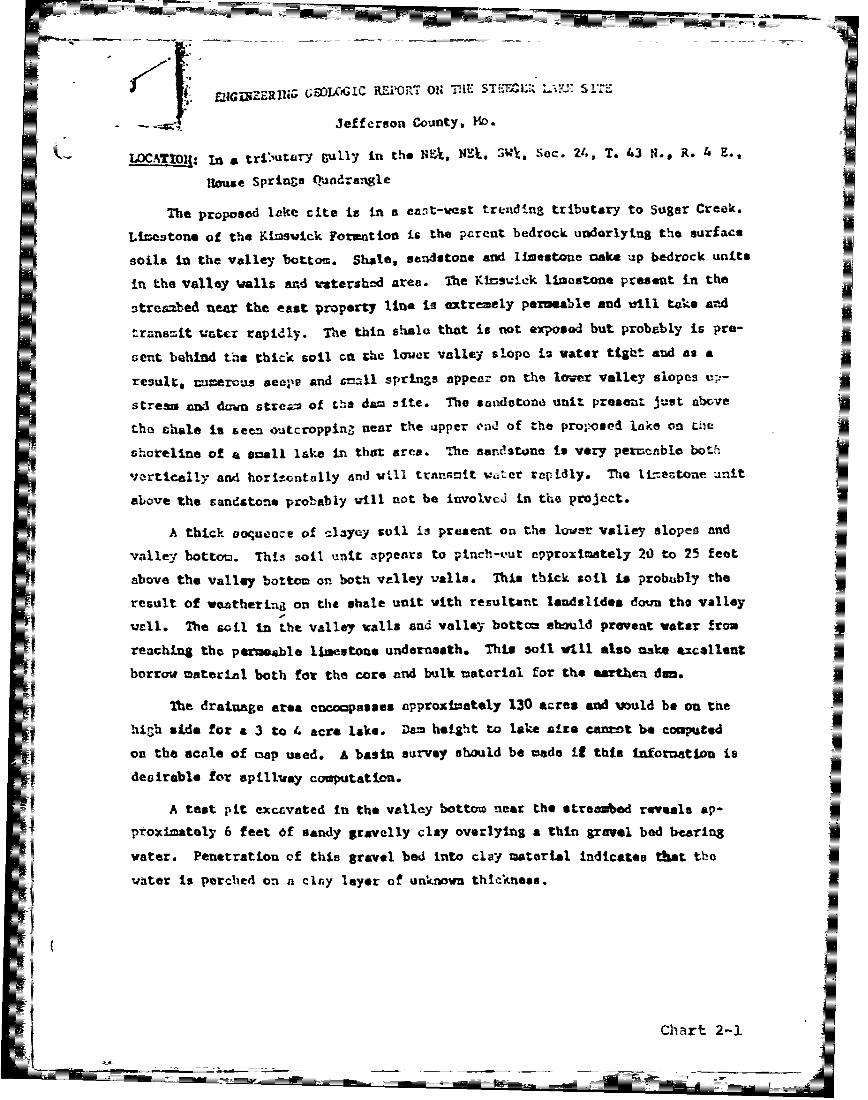
EatUNGU(ERPi W GC REPs OJN 3 JIE .- ;AJ L43 *'-KU'-
Jefferson County, HD_.
WCATIOII: In a trCutarY Vlly in the NF. NZk. SW\, Sec. 24, T. 43 N.g R. 4 E.,
House Springs Qadrangle
The proposed lake cite is in a east-vest trendin3 tributary to Sugar Creek.
Limestone of the Kimswick Formation is the parent bedrock underlying the surface
soils in the valley bottom. Shale, sandstone and limestone oake up bedrock units
in the valley walls and watershed area. The Kinsvick limestone present in the
streabed near the east property line is extremely permeable and will take and
transmit water rapidly. The thin shale that is not exposed but probably is pre-
sent behind the thick soil cn the lower valley slope is water tight and as a
result, nurerous seeps and call springts appear on the lower valley slopes up-
stream and d-wn strea of the dam site. The sandstone unit present Just above
- the thaie is seen Outcropping near the upper end of the proposed lake 0n the
shoreline of a small lake in that area. The sandstone is very permeable both
Vertically and horizontally and will trnnsmit ater rapidly. Th e Irtstoae unit
above the sandstone probably will not be involved in the project.
A thick oequence of clayey soil is present on the lower valley slopes and
valley bottom. This soil unit appears to pinch-eut epproximately 20 to 25 feet
above the valley bottom on both valley walls. This thick soil is probably the
result of weatherind on the shale unit with resultant landslides down the valley
W-ll. The soil in the valley walls and valley bottom sbould prevent water fr-m
reAchinug the permeable limestone underneath. This soil w ill also make excellent
borrow material both for the core and bulk material for the earthen dan.
The draiuage area encocpasses approximately 130 acres aMd vould be on the
high side for a 3 to 4 acre lake. Dam height to lake site cant be computed
on the scale of map used. A basin survey should be made ifE this infortatiou is
desirable for spillway computation.
A test pit extcvated in the valley bottom near the streaed reveals ap-
proximately 6 feet of sandy gravelly clay overlying a thin gravel bed bearing
water. Penetration of this gravel bed into clay material Indicates that the
water is perched on a clr.y layer of unknown thickness.
Chart 2-1

~-2-
sin eAry, sufficient amounts of clay tppear to be present in the valley
-- walls and valley bottom Casking the permeable bedrock that would make water im-
poundment geologically Lenssible in this tre.
It is recowended that the core t extended to and into the clay laycr that
is preset underneath the waterbearing gra-el all the way across the valley bot-
too. As the core starts up the valley Ils, seating the core in 3 to 4 fact of
clay material wuld be sufficient. Unless sand amd gravel Lesas are present in
the clay in the lover valley walls, coring all the way to bedrock is not neces-
sary.
The core depth across the valley bottom may be uneven due to old channels -
that uay be present in the fill zterLal. As the core progresseo across the val-
vey bottom, it should bottom out in the clay layer present underneath the gravel
and clay for the core backfilled on ci*y material. It will be important to con-
trot water during the back-fill operation as the backfill should mot be accon-
plished with water in the trench.
In the event that the clay layer under the water bearing gravel is thin (leas
than 2-3 feet), then the core should penetrate to bedrock across the valley bottom.
2). SpilIway design will be eoetihat critical due to the large and very
steep watershed.
3). Bedrock should not be ezposed i the lover valley walls below the water-
line vhan excavating for borrow material. At least 4 to 3 or perhaps 6 feet of
clay should be left masking the bedrock balow the waterline. To repeat, the soil
will make the lake hold water as the bedrock is very permeable.
4)o As a precautionary casure, the streabed should be filled to general
floodplain elevation upstream of the dais for svceral hundred feet. The stresbed
will ba a weak point in the core area and filling of the streabed with borrow
matertal will help alleviate this weak point.
5). Additional borrow uaterial probably can be obtained in the upper end of
the lake in the shallow water area.
- 2
Chart 2-2
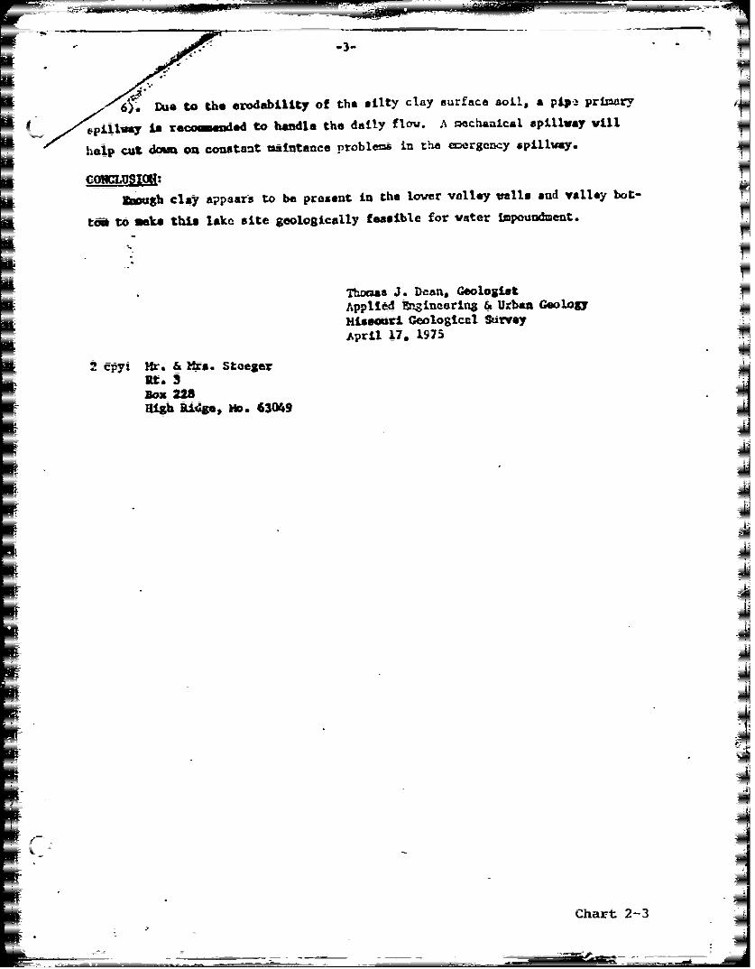
-3-.-
6) Due to the erodability of the silty clay surface soil, a pip- primary
5Spilflwy is recommended to handle the daily flow. A mechanical spillway will
help cut domn on constant aintance problems in the uergency spillnry.
Savough clay appars to be present in the lower valley malls and valley boL-
ta to sake this lake site geologically feasible for water Impoundment.
Thomas J. Dean, GeologistApplied &.gineering & Urban GeologyMissouri Geological SurveyApril 17, 1975
2 cpyi Hr. & Mirs. StoegerRt.° 3
Box 228fligh Rifs, No. 63049
Chart 2-3

N IDE-DUM -0 THE EMP G.=. REXLAKE
- JFFERSON f %-X,--V c
LOCATION: NE, NEa, SW , Sec. 24, i 431 N., R. 4 L., house S-prings Quadranq le.
The lake was constructed and tne aiKe fillCd to a considerable depth anl thendrained down to a relatively stable water line according to the land owner.
The tributar Stream .ee.din the lae is "' a osinc strmn setin in the rim-mswick formation. The relatively thi-c - - present in tt ik - h- nearthe dam evidently hve some wealK s-os -he ustr . -eacheCs ot lake- Asink was renrted 1% irC. it~eucr that was oca-ed dur-n-=.-. con-tr-cti. s'r-ude.y-these weak points allow the lake to 'pc-- u:p o o ts -- a- p-ad to te _oint wherevertical water loss takes olace into the under.ino ver ereabe bed rock. Accord-ing to ..r. Steeger, the water does n-- reapear at a r.abn ai diance dolstream
of the darn. This is somewh.at character i st C of the nd erl-n- nedirection of travel of water 1n the .rock doe Cid wth the directionthe valley.
Padding of t-he upstream- ortion of thlkecappears t bN- the only krnown easzlbemethod of preventina vertical water loss th-h ak- spS -n the natural cly la-e-a padding oneration should start -:ell onto the Zone that 2 oe hold water withextended upstream to the upnnr e - - of the Cx-cavat area in the valley botto t i0thought at this time that only -h bottom needs to ha -cadde as the clay in the lo-er valley walls on the upper end of the !ake a-ppears to be of sufficient quanI ity topond water.
In addition to the naddinc of the lake -hottom, it is reco-nended that a core beexcavated to bedrock in he uoer end of the " c o f - rr the Creek itnatIS going prso unergroud) to t surf ace and onao the clay Patonser ted inthe lake 'o-tom. This , if successful, would -- c c eatics os water thatwould help overcome seepae and evap-oration losse-s- Et -sn- k-n-- whether- = t e"ater cominc down the creel that is now bein' lost is shalow -nou--h to interceptwith a core rench. It is thought at this tImse < '-at wou z e co r tn t-effort to make the attempt.
%AIf sufficient clay is not available for a cmriete Pad (18 inches to 2 feet in
compacted thickness) then it would he well to scrape the bottom area a sufficientdepth to locate the old collaoses i(that are nroban-1 v now q-avel filled) an repairthem on an individual basis. T- 7 V well be that only one or tw snaIl, ancientcollapse areas are present that are robbing the- lake ow they cno-m-4 ,_-O wtrifteya.nlocated, however, then an entire pa d would r- .
The severe landslidinc problem on the northeastern side of the lake is cause-by water moving out of the Bushberg sandstone. Iose sand that has accumulated onAthe slope in this area over many many years :ecomes saturated and slides wahen thetoe of the natural slope has been removed su-c- as for Jmnrove.ment of a lake shore-line. *Whiie this sliding action should not affect the lake from the water holding
Chart 2-4

Th-tzrand to e 10e en1aLuthea water :ane a G ~ ~ ~ ~ ~ ~ ~ -- -- r eV=vece - -- N=
thej. -a -r - 0 t;
,the SlIe rea torhvicallv C AA -aredf cutting a trench acr--- c' lun a drai
=ane into the moaerzla± so that -- er--u nndraan o h s-- rlake ratner t~nan- saturwate the =a-~ at lower -l-t ions.
core -r~ ~
-~US -- -f--g
Engneeri= q LV Section
May
Char-t 2-5

AP PfEND IX A
INSPECTION1 P1OTOGPRAHSI

I T
I-;

E4
E-4
0
u 0_
0~ I-4
0. 0
Ctjjo t(
< 0l
~V

APPENDIX 6
HYDROLOGIC AND HYDRAULIC ANALYSES

IHYDROLOGIC AND HYDRAULIC COMPUTATIONS
1. The HEC-1 Dam Safety Version (July 1978, Modified 26 February 1979)
program was used to develop inflow and outflow hydrographs and dam overt6pping
analyses, with hydrologic inputs as follows:
a. Probable maximum precipitation (200 sq. mile, 24-hour value equals
25.5 inches) from Hydrometeorological Report No. 33. The
precipitation data used in the analysis of the 1 percent (100-year
frequency) flood was provided by the St. Louis District, Corps of
Engineers.
b. Drainage area = 0.194 square miles 124 acres.
c. SCS parameters:
Time of Concentration (Tc) (llL 0.385 = 0.200 hours
Where: Tc = Travel time of water from hydraulically most distant
point to point of interest, hours.
L = Length of longest watercourse = 0.578 miles.
H = Elevation difference = 151 feet.
The time of concentration (Tc ) was obtained using Method C as
cdescribed in Figure 30, "Design of Small Dams", by the United StatesDepartment of the Interior, Bureau of Reclamation, and was verified
using average channel velocity estimates and watercourse lengths.
Lag time = 0.120 hours (0.60 Tc)
Hydrologic soil group 0 (100% Gasconade Series with steep wooded
hillsides per SCS Missouri General Soil Map)
Soil type CN = 79 (AMC II, 100-yr flood condition)
( = 91 (AMC III, PMF condition)
B-i

2. The trapezoidal spillway section consists of a broad-crested section
for which conventional weir formulas do not apply.
Spillway release rates were determined as follows:
a. Spillway crest section properties (areas, "a", and top width, "t")
were computed for various depths, "d".
b. It was assumed that flow over the spillway crest would occur at
critical depth. Flow at critical depth was computed as
c 3 (a)0.5 for the various depths, "d". Correspondingt
velocities (vc) and velocity heads (H vc) were determined usingcv
conventional formulas.* Reference, "Handbook of Hydraulics", Fifth
Edition, by King & Brater, page 8-7.
c. Static lake levels corresponding to the various flow values passing
the "oillway were computed as critical depths plus critical velocity
heads (d + H ), and the relationship between lake level andc vcspillway discharge was thus obtained. The procedure neglects the
minor insignifcant friction losses across the length of the spillway.
d. The spillway discharges and corresponding elevations were entered on
the Y4 and Y5 cards. Calculations for determining the spillway
capacity are presented on pages B-11 through B-13.
3. The profile of the dam crest is irregular and flow over the dam cannot
be determined by application of conventional weir formulas. Crest length and
elevation data for the dam crest proper were entered into the HEC-1 Program on
the $L and $V cards. The program assumes that flow over the dam crest section
occurs at critical depth and computes internally the flow over the dam crest
and adds this flow to the fiow over the spillway as entered on the Y4 and Y5
cards.
2Vc = ,Hvc='"a 2g
B-2

F- i
z x-
I3 M
1j I
I I I-
ie
IB-3

I-CiC
LL-- l I
- L
<r I A
-4I

I. -V
Ekrl
.4 1 .I ...w 0.
-i LfrL- t~2X :, I N c
CI -. . . . . .. . .S
..4 LL a
K-j :I

F77-
-42 4
. . ... ..
Cp Q
I-' -
.1.14
. . .I ii I . . . . .
-44 tiIt a i i-in 0'. CU
P.-

CM SICF i CATIO4I., I DY j- I-.A iFRT tS:144
0* ~ . A A -
L, Vc-r. 1rm
.ki-L144 hYLptLe
irflLE.5 ILKt, iizni R;iT -I6'R w r- w 1 it' 0
S ~ ~ r. FI R6 pU P' r
S7tP STXR( ELThR RIJEL EPAI'N STRWS RlhiM Lta..-m _nl
Mr:r( -1.o UI'tES-S -1.00 EFFECT 1.24 91.01
Th- 0.0Cy LAG- .12
HREgs(N DATi,
T tE 11h-CitENT TOO LAF{K--{tP IS ;-I LAG/IZ
~~~P 4.IK6. 2. .2VL _c

-w-
A.[A M.1I PERIOD PAIN1 E} L .CS 6 C E I. I.? PERIOD kliJ ExC$ L% t(P 0
-TDl ._ i A .QI .Y-. .vq V. l.U) ±A.':. .a :. A T .--- F-- --? 7
1.01 .1( 2 .01 0. [A .01 0. 1.01 12.10 14. .22 .21 .(0 224.1.01 .15 .01 0.'X .. 0. 1.01 12.15 147 .22 2 . 279.
1.01 .40 v .01 O) . t. .l '' 2"1.01 .45 9 .01 1A.) ." 0. 1 . 5.C .2 30
4.4.4.....!t - CC,', .21 .t .: 32x
1..1 .55 i .0 0. A '. '2t .. .. "" "21.°1.01 1Am 12' .1' " "-.. i .01 0.(<) .01 0.-'.. ,., .22. .21 .0:0 321.-
1.01 1.05 13 .01 0.(U .01 0. .- .'W 'v- .2 .21 .(0 334.1.01 1.1 14 .01 . .01 .V' 'C jcr, .26 .26 .o4 159.
1.01 1.15 15 .01 .00 .01 0. "2 '. KS' .3jo ,Al. 0. ellb ¢,. 1.20 16 .01 .00' .01 0. '" ... " ;" . .~.16 . 31
1 ,125 1? .() .(' i.1i .. - '.,~ ±M1 ,6 ./*$ .WX 94.
J,.va" 1..3 3 .0' ." 'a: .: a. . 1 -' a..c-'4 " L... . .2. .25~ .('J' '. e
'01.35 19 0"0 .01 2. AM '3 13 .26 .26 .03 2I7.li0 1.40 20. .01 .(-< .1 *. 1'01 1.40 164,. .26,'" .26 .00 s.:..
1.01 1.45 21 " A, 0 s 137. 45 16.,.50 22 . 3. .. 1 .50 1k4 .26 .26 .(0 W
1.a;1 .55 ' ' 23 0. ..0 .0 i. .l 3.5 167 " .2., .26' .0<, 3.0
1 ..0 24 " ., . ".0 "" .26 .26 .06
U5 . 5. .i .05 Ls .-- .32*. i .1 . . 1 .(' .1(.,.. 0 "=. ,' ..- . ...." .32.L .00 -'4
j.w C -. 0 (< O .... .1 C 17 .31.1-A ."-. ii: .1= ..¢V. .O .. 1 .14' ,_ J,'= .* ,% .0 ( _- ____78
'V ." 01 '' .3 . . .. ..
4-V 0 Ok V 4-4
S.a .j A x
,."_. z.35 3- 1 ..) I. 'i.014i.35 175 33 .32 .00) -
i.' .40 32' .v" -O .'1 t,. ?m l .4 176 .3 , .4•1, .t(<) .~
-- :.' 2..- 4.- 3-.: .45 17 "" .0( _ __
1. 4 1 . N,. ' i¢ . .O 7 ,. ,
2s .32 'Al
.01 . 05'- , 37 .01 . u1 . 1 "'O 5 ... 1 1 .2: i0 .,00 4 4?;_1t .01. 3.10-. :6 .01 .vl ""l9 4.(g,'",. .-r-.' .40 , A"?"1. 2.1 A .'I 50 1-.IK
A.- VI .. .. I'*i
1.... ..... .O-f .4 "' '" .a9 ,59 .00 77l.
1.01~~~C 323 42MY 4 .. 0 ±I
S1.0; 3.-3, 43a .(, 01 . 01. 10. " Vz. 1535 I.s:- .. 7 ±.76 .01 2162v-.: 1.01 3.4I0 4,4, .01 .01 1.," 0. 2' ' Th"' .,-v we "r @ i i 0. 9 .04. 26 5..
I.01 3.A 5 45 .101 I, . l 15, j i ,. ,? .o.211
K16i
t1.0 3.50 ,6 .01 .05. . 11 .. ., .3? .. 154.
-- . 1 .0 1 .,5 5 ± 78 .( 1 .* " " ' "= . 1. 1 i .( 0 Q ' "0 )2 .4 6 . .0 0: 1 1 1 4 .ii %1.0 1 4 .(t3 48 . (,I-" O'm " .40 .? 0:8 3
B-B

END-OF-PERIOD FLOW (Cont'd)
=1.01 4.10 50 .(,I .J1 .01, 12. 101 L..l0 ;1d) J30 558r.1.01 WA0. : .,1 ., O . .- .97.
1.01 4.15 51 .01 .01 497 .-. . .
1.01 4.210 12 .('1 . . 1.I1 14.0 196 .1 3 .0 .0 471.1.01 4.25 3 .01 .01 .1 1 11 16. I 461.1.01 4..0 54 .01 .01 .01 12. 10 1'.( i .30 47.1.014.5.c i. .0 16,35 -8 .30 .30 . -,
1.01 4.40 56 .01 .01 .,1 3. .01 16.40 200! .30 . . 455.1.01 4.45 57 .01 .01 .01 1.. 1.1 I6.45 01l .30 .3A 455.
1.01 4.55 59 .01 .01 .r 1. .. . .3. .30 55.1.01 5.00 60 .01 .01 ' 1'. '1 7' i ( ,= :" .3,0 .2.0 "AC"
1.01 5.i 61 01 .I' .0 - 13. i.dl i7. 0 . .24i .24
1.01 5.1I0 62 ,0! .01 ._I. 14.".. .)I 11.10 -'- .24 .24" .,. 3'i8.1.01 5.15 63 .01 .01' .(o 14. * n, ,fl 'L . .24.2.. .. 75
7.(6 - -4
1.01 5.,0 .6 .01 .0t 14.17 .24 .11.0 35.
A1.01 5.25 6 .01 .U1 .. .A 1 4.1.01 5.40 u-: .01 .01 14. 24•L 1,m, * ., M.
-.- ,.-. .. - -, . " -- ',r.
I: c : : 1~ 1-%r ba'3 Al.k J2 L 4~*1 , n .,. ,...6 O :," ' . . .. h .~_
1.01 6.0 72 .01 .01 .i "" . .5"-0 5. _341,.. 1) :).01, 10." 0 . _
1.01 6.05 73 .016 ( - q-. .0-5 .@_ --* --- .24 .2 ... @ 29.1.01 5.10 74 .06 .05 465. 1.01 -.A"
1.01 6.05 75 .06 All N1.1 M.1.a : c.0-' L A.-7. , ) '--. - .t)* AO •t "N
'I.(I I ID A ( .in IV ' ,,M,. I;':. 1t ... AZ:2 .f) ;
-!.()1 6. 15 A5 K:8 (Q Q(2 ./. ,.. ) , :, ,,:1.01 6.20t 76 .06 .05 .0 67. 1 I f.2 20 02 . 02 . 0
11.01 6.25 77 .06 .015 .1 71. 1.01 18. , ". .12 .02 .o 207.1.01 6.30 78 .06 .05 .1 73. 1.01 *. '.3 .4( 193.
r1.01 6.35 79 .06 1.0 1C~ 1,- 0~ 1011.01 6.40 80 .0 .05 . I1 76. 1.0 . .0.--18
1.01 Z.45 81 06 .65 ! 71.1 - .042 .0 .00 15,1.01 6.50-t., .,6 •06 •.01 .0 .2 .1
1I.01 ',55 1 (. •6 0 .t41 1h. ,.3zz- ""19..65 .02 17.
1.01 7. . 0 1 .0 1 1. "1.
1.0 -17.15 -6 Z. Z.0 i 1
1.01 "7.> h. a0 .t% 6j44 d ~ : r vL.01 7.15 87 . .,.
1.01 7.4 .t% .( . - • t ". -*.. Z5. -l 9..
1.01 7.5 7• 0 O .(L5 ,4J. S-4 ..0. .-. S.
1.01 8. !" ". 45 ......
.-r.. .. -. A'tl :< . --2 LL '2 . : ":
1.-l .- 52
.0 8.1 .(.. C
10101 K2 02
TU

END-OF-PERIOD FLOW (Cont'd)
____ -1 . 10 ., .I..A'. -' .2 ,' 3 .
=lf-t M-).!'!(-'2 .=.* 102 a 1h.'. ..i01104 .v .- 6 2..4.. Th.0 232.
.. ... .05 .0.6 A; 6% :. i
1i %.55 107 .% .- . 1. 2. .32.''1 Ol 10 . (. . 'I. 2" 2 - 2 .00 s".
.W 9.W Mi% VIO .f A5 st. * A.-
lv, .. 0 11! .I. . i.! - - . . !Us' 9.15 0 j.- falK
T. .. 19 Il . Or .5 ".. i.., -- JW .1.01 9.25 113 .06 .0-6 .( 1. 0- 4 - "" .a. 32.IAI v.3;) 114 .t1 .66 .00 91. '56 0s A(-
'' 4( 1 I- A'- A. _ _ _ _
1 9.1 .45 117 .06 .('6 .0 9. - .
1.0' 9.55 1199 .0& 06 (I 91. . -" -a .. 02,-
±l.J. 10.00 120 .06 .06o .00 V . .. u ., "t0 ,.2: 0 -0 .0 32.
li-, 01, Al; 9:,. .OU tD 32.
T1 7 47D ' 0
1 0! v.15 12$ .06 ... M 92.,-, - -. 2-7 " - 32.-10.i5 126 06 .0i .00 2. I. 2. 2 6 . .. . 00; 2 320
1-±1.3 2 .06"- .06 .0 .9. ivti .3 270 " " .00' 32.-1.v1 10.40 12 .06 .06 .00 92. 1.01 22.4 "3
11.01 /i.ts U.? .0-. .k5 .00 * A . iv--'" i .c¢ . ... '- .0 .,w " -
=it1 10.30 130 .0-6 .6 .0i 92. 1.01 223 274 .02 .02 .00 32.1.01 1!.5 5 1 7 AV 2. 2.5 .00AM -( "-- . - -
. c 'I, .- .. 0
1.01 11.0 143 A .A_. A* 9 5 2U4 .
~~~3 O.i5 01=__ #118 .i1
1..01 1 (61 .0il l 4L- VW A
IS0 12:6 Air
.S ) 14 Awl..{ 2K) ia 2_p=o 101 .35 13 u.< "- wk 93. U_ e:_ 'h5 -283- ( o : .P02
1.01 '1.40 140 . L 0&tjC 93. .A UL4 284 00 32.
10 u11.50S 1 42 1 .0 .~ 0. 93. 1.13. 23.5: 43 3t a Y2. 11. 14: (k I !a, .S 3.5. 2M .0=: AilOz
a:4p 5rK 2, 04 012 W.
SI' 33.116550131.8 42. ')(IM 1419.55) I
3113 16. 15. 11IIOES 25. 73 3~ 3'
t,.f 266 . -4a - , -
SB-IO

.7%_ _ z~
I 110
cio
1U 1
il 4n a -.- :=
I I IML L

bi D
LL I dn
CLL
I-I
w-.
(I x
U ~ Li Cr C <
~ICE
B - 12

HORNER & SHIFRIN, INC.- CONULIINO ENGINEERS
5200 OAI(LANO AVE. St LOWSt. MO 63 HETN L.......O0___
5 jETF.Lg
TI.- TAT
______B __ _ _ _ __ _ _ _ __ _ _ _ _ f _ AE_ _
0 q tq. 't ~A ~L. o
i. z3R
I-
z j
rJ'A
= I7o Z 1 r'
I4
-1P 1
-w stf TI
Z) x -Nil
fl~ -r-1

HORNER & SI-IFRIN, INC.320 CONSULTING ENGINEERS 630 ________
$20OAKLAND AVE ST LOUIS. MO-10 ______Jo
SUBJECT FILE
B- r" t; -
/-J
-ZF N
_ - 0;~~N M -1 1
Nc -
-40
ri j.
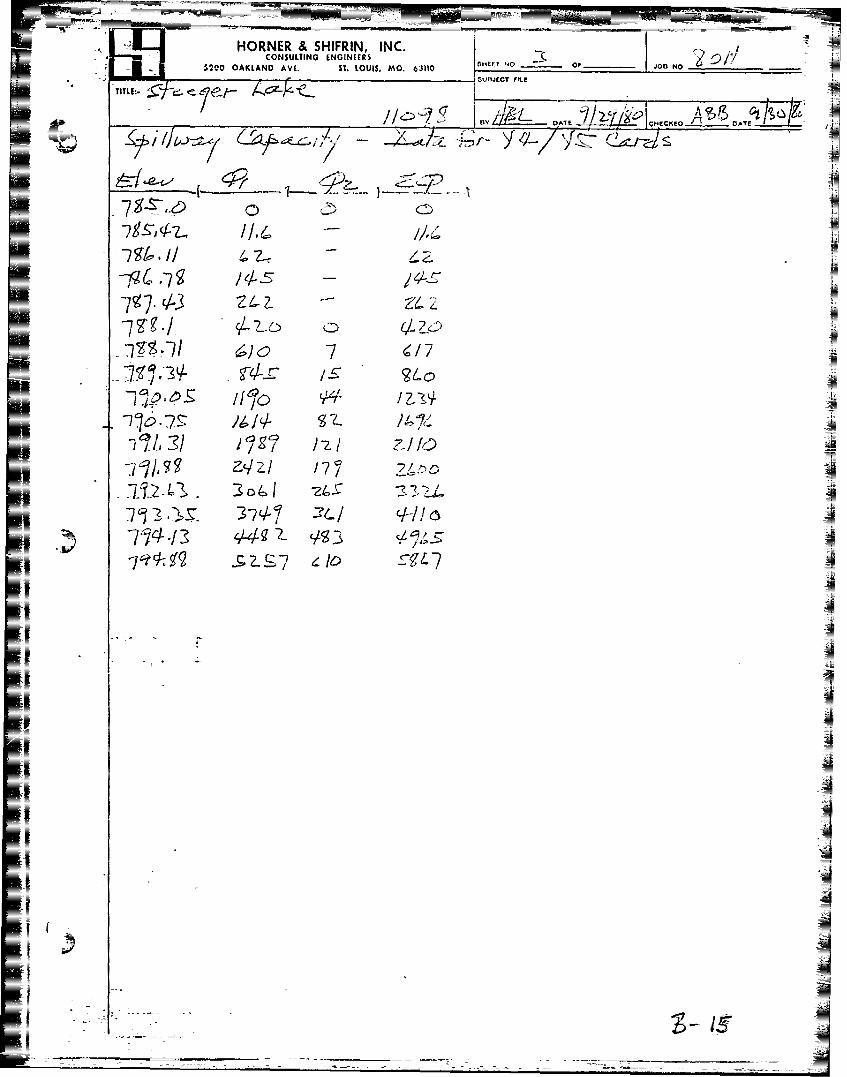
HORNER & SHIFRIN, INC.2
I200: OAKAN AVE ST LOISAO.611OBN
_ _ _ _T IL
/1' (,A
I/,1z /soIDATE.I -cE~ AEt
7177
77fi~72.~> 2o44- 2~
0, L
f70___