Embed Size (px)
Citation preview
www.intorq.com
setting the standard
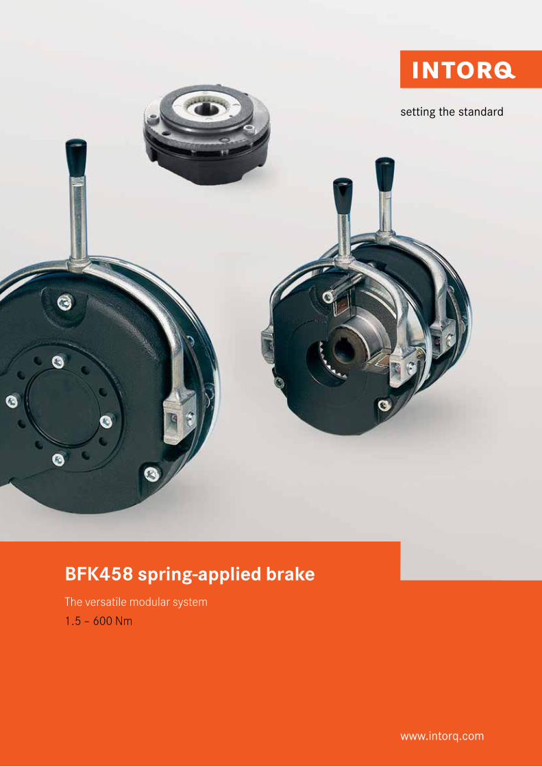
BFK458 spring-applied brakeThe versatile modular system
1.5 – 600 Nm
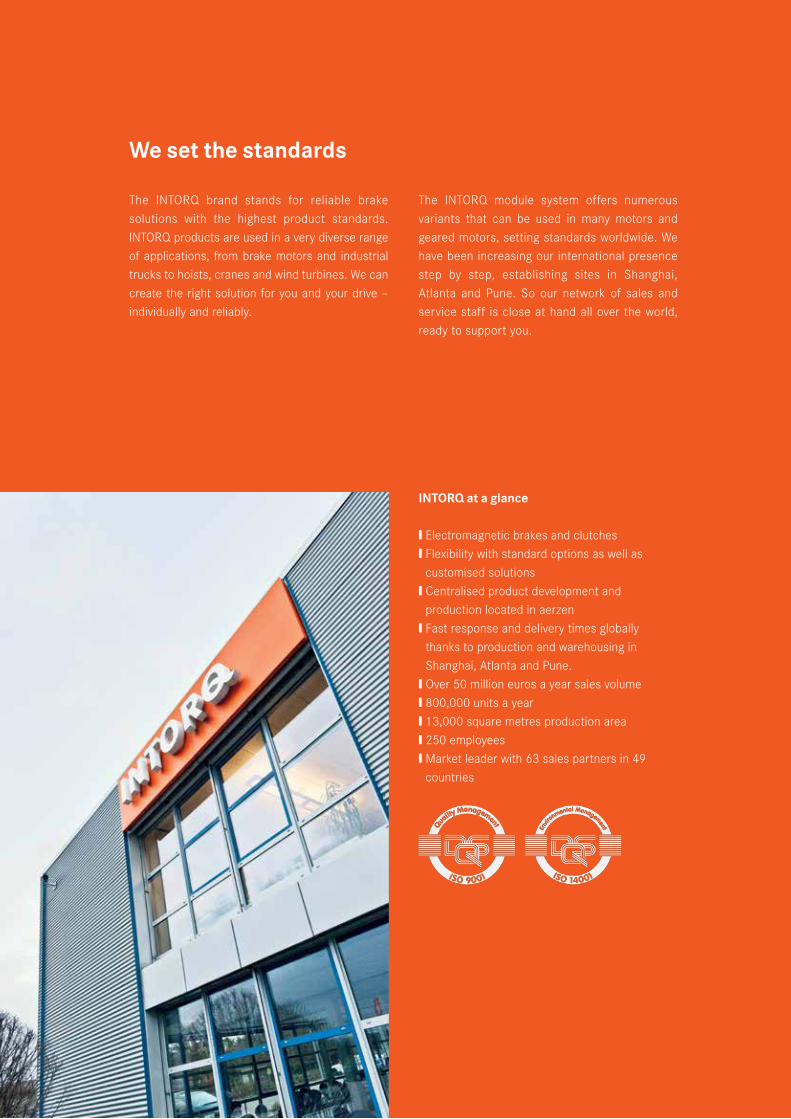
The INTORQ brand stands for reliable brake solutions with the highest product standards. INTORQ products are used in a very diverse range of applications, from brake motors and industrial trucks to hoists, cranes and wind turbines. We can create the right solution for you and your drive – individually and reliably.
The INTORQ module system offers numerous variants that can be used in many motors and geared motors, setting standards worldwide. We have been increasing our international presence step by step, establishing sites in Shanghai, Atlanta and Pune. So our network of sales and service staff is close at hand all over the world, ready to support you.
We set the standards
INTORQ at a glance
❙ Electromagnetic brakes and clutches ❙ Flexibility with standard options as well as
customised solutions❙ Centralised product development and
production located in aerzen❙ Fast response and delivery times globally
thanks to production and warehousing in Shanghai, Atlanta and Pune.
❙ Over 50 million euros a year sales volume❙ 800,000 units a year ❙ 13,000 square metres production area❙ 250 employees❙ Market leader with 63 sales partners in 49
countries
INTORQ I BFK458 spring-applied brake
This modular system forms the basis for a product range that offers versions tailored for almost any task. The BFK458 spring-applied brake, as a standard product, can be used anywhere, but its modular structure also meets the requirements of specific industries. Its strength lies in its versatility.
Electromagnetically released spring-applied brakes are used wherever masses in motion have to be decelerated as quickly as possible or where masses must be held in a defined position. The braking force is applied by tappet springs. Thus the braking torque generated by friction locking remains available in the deenergised status – even in the event of mains failure. The brake is released electromagnetically.
The main components of the modular system are the two basic modules E (adjustable braking torque) and N (non-adjustable braking torque).
The greatest degree of flexibility is achieved for a broad range of applications by combining the basic modules with specific modules. This catalogue is designed to assist you in selecting and ordering your desired spring-applied brake quickly and easily.
Fields of application
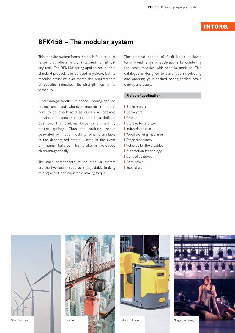
❙ Brake motors❙ Conveyors❙ Cranes❙ Storage technology❙ Industrial trucks❙ Wood working machines❙ Stage machinery❙ Vehicles for the disabled❙ Automation technology❙ Controlled drives❙ Gate drives❙ Escalators
BFK458 – The modular system
Cranes Industrial trucks Stage machineryWind turbines
4I5 INTORQ I BFK458 spring-applied brake
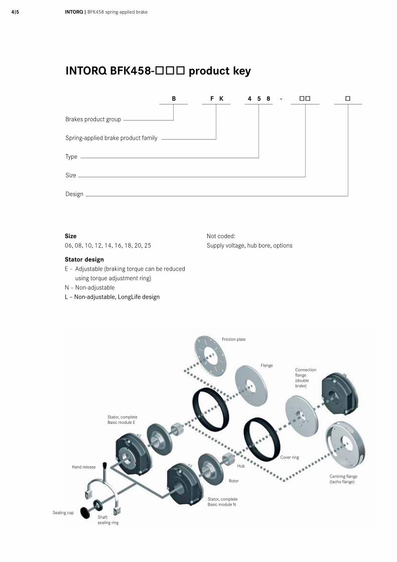
INTORQ BFK458-òòò product key
Friction plate
FlangeConnectionflange (double brake)
Centring flange(tacho flange)
Cover ring
Hub
Rotor
Stator, completeBasic module N
Plug
Shaftsealing ring
Stator, completeBasic module E
Hand release
Size06, 08, 10, 12, 14, 16, 18, 20, 25
Stator designE – Adjustable (braking torque can be reduced
using torque adjustment ring) N – Non-adjustableL – Non-adjustable, LongLife design
Not coded:Supply voltage, hub bore, options
B F K 4 5 8 - òò ò
Brakes product group
Spring-applied brake product family
Type
Size
Design
Hub
Sealing cap
Contents
Product key .....................................................4
List of abbreviations .......................................5
Product information ........................................6
Functional principle ........................................7
Technical data
Rated torques ....................................................8
Basic module E ...............................................10
Basic module N ................................................12
2 x basic module N + connection flange ........14
Basic module N + tacho flange .........................15
Rated data .......................................................16
Operating times ....................................... 16/17
Service life and wear ........................................18
Accessories
Hand release/flange/friction plate ................. 19
Centring flange/connection flange/cover ring 20
Brake cover ......................................................21
Microswitch ....................................................22
Terminal box ...................................................23
Rectifier type code ..........................................24
Spark suppressor 14.198.00 ............................24
Bridge rectifier + half-wave rectifier ...................25
Connection plans .............................................29
Supply voltage selection table ...........................31
Dimensioning
Basics ..............................................................32
Example calculation .........................................33
Overview ........................................................34
List of abbreviations
PN [W] Rated coil power at rated voltage and 20°CUN [V DC] Rated coil voltageMK [Nm] Rated torque of the brake at a relative speed of 100 r/minMdyn [Nm] dynamic brake torque, measured at constant speed of rotationML [Nm] Load torque, torque that the static load produces at the motor shaft∆n0 [r/min] Initial relative speed of the brakeJL [kgm2] moment of inertia of the load, referred to referred to the output shaft (load shaft)Q [J] Heat/energyQE [J] Maximum permissible friction work per switching cycle, thermal rating of the brakeQsmax [J] maximum permissible friction work during cyclic switching, depending on the operating frequencySh [1/h] Operating frequency, the number of repeated operations per unit time
Shue [1/h] transitional operating frequency, thermal rating of the brake/clutchShmax [1/h] Maximum permissible operating frequency, depending on the friction work per operationsLN [mm] Rated air gapsHL [mm] Hand-release air gap, setting dimension of hand-releaset1 [s] Engagement time, the total of the reaction delay and torque rise time t1 = t11 + t12t2 [s] Disengagement time, time from switching the stator until the torque has reduced to 0.1 MKt3 [s] Slipping time to standstill (after t11)t11 [s] Delay time when connecting,
time from disconnecting the voltage until the torque begins to riset12 [s] Rise time of braking torque, time from
beginning of rise of torque until braking torque is reached
6I7 INTORQ I BFK458 spring-applied brake
A powerful and complete range❙ 9 sizes❙ Standard voltages [V DC] 24, 96, 103, 170, 180, 190, 205
❙ Graduated torque range from 1.5 - 600 Nm❙ Short delivery times for the complete range thanks to optimised logistics
❙ Enclosure according to IP00 ... IP55, depending on the special operating conditions, see technical data sheet
❙ ATEX: In accordance with Group II, Category 3G/D, the product is suitable for use in potentially explosive atmosphere of zone 2 (gases and vapours) and zone 22 (dust) for steady-state operation (holding or parking brake) and temperature class T4.
Versatile❙ Modular structure for virtually all applications
Torque transmission❙ Designed for dry running
Quick and easy mounting❙ Preset air gap❙ Special machining of the friction surfaces ensures that the rated torques are achieved after very few switching operations
❙ No locating bearing is required on the brake
Durable❙ The insulation system to temperature class F (155°C) ensures that the winding has a long service life❙ The brakes are designed for 100% duty time (current applied to the brake)
Low maintenance❙ Long rotor/hub connection with low rate of wear and a tried-and-tested involute gear
❙ Asbestos-free and solvent-free friction lining with low rate of wear
Reliable❙ The certified ISO 9001 and ISO 14001 quality assurance system provides the basis for consistently high-quality products
❙ Production and testing to VDE 0580
Options❙ Hand release for all sizes, both directions can be used for release and mounting (exception: tacho brake)
❙ Noise-reduced designs❙ Various types of corrosion protection and enclosures
❙ Microswitches used to monitor air gap and wear (size 12 and above)
❙ Monitoring of Hand release function ❙ Non-standard voltages and bores on request❙ Pulse width modulation (PWM), sizes 06 – 18 Partial discharge free brake has been developed for operation with the pulse width modulated DC bus voltage of a frequency inverter
Rated coil voltage UN=103V DC
LongLife design BFK458-L❙ Armature plate with low backlash and reinforced torque support
❙ Tappet springs with guide pins for protection against shearing forces
❙ Aluminium rotor with toothed intermediate ring: friction lining and tooth system with low rates of wear
CCV (Cold Climate Version), temperature-resistant up to -40˚C ❙ CCV design configurable for all sizes in the modular system
- Use of chrome-plated friction surfaces (armature plate and flange)
❙ The following components are also approved for use up to -40˚C - Rotor with sleeve (noise-reduced) - Hand release - Terminal box - Microswitch - Caps E and N - Shaft sealing rings (available on request)
Product information
INTORQ 155-1
E318895
up to -40˚C
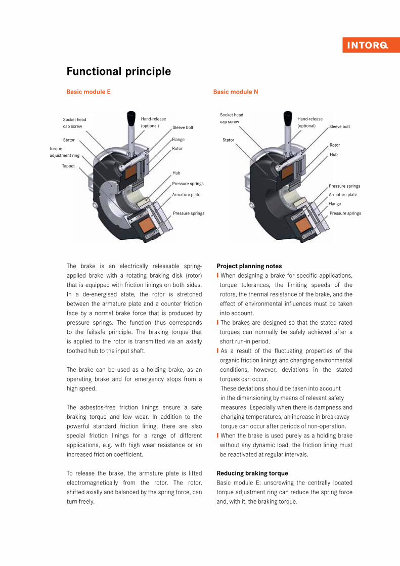
Functional principle
Basic module E Basic module N
The brake is an electrically releasable spring-applied brake with a rotating braking disk (rotor) that is equipped with friction linings on both sides. In a de-energised state, the rotor is stretched between the armature plate and a counter friction face by a normal brake force that is produced by pressure springs. The function thus corresponds to the failsafe principle. The braking torque that is applied to the rotor is transmitted via an axially toothed hub to the input shaft.
The brake can be used as a holding brake, as an operating brake and for emergency stops from a high speed.
The asbestos-free friction linings ensure a safe braking torque and low wear. In addition to the powerful standard friction lining, there are also special friction linings for a range of different applications, e.g. with high wear resistance or an increased friction coefficient.
To release the brake, the armature plate is lifted electromagnetically from the rotor. The rotor, shifted axially and balanced by the spring force, can turn freely.
Project planning notes❙ When designing a brake for specific applications, torque tolerances, the limiting speeds of the rotors, the thermal resistance of the brake, and the effect of environmental influences must be taken into account. ❙ The brakes are designed so that the stated rated torques can normally be safely achieved after a short run-in period.❙ As a result of the fluctuating properties of the organic friction linings and changing environmental conditions, however, deviations in the stated torques can occur.
These deviations should be taken into account in the dimensioning by means of relevant safety measures. Especially when there is dampness and changing temperatures, an increase in breakaway torque can occur after periods of non-operation. ❙ When the brake is used purely as a holding brake without any dynamic load, the friction lining must be reactivated at regular intervals.
Reducing braking torque Basic module E: unscrewing the centrally located torque adjustment ring can reduce the spring force and, with it, the braking torque.
torque adjustment ring
Armature plate
Hub
Rotor
Hand-release(optional)
Pressure springs
Sleeve bolt
Socket head cap screw
Stator
Pressure springs
Flange
Tappet
Armature plate
Hub
Rotor
Hand-release(optional)
Pressure springs
Sleeve bolt
Stator
Pressure springs
Flange
Socket head cap screw
INTORQ I BFK458 spring-applied brake8I9
Technical data
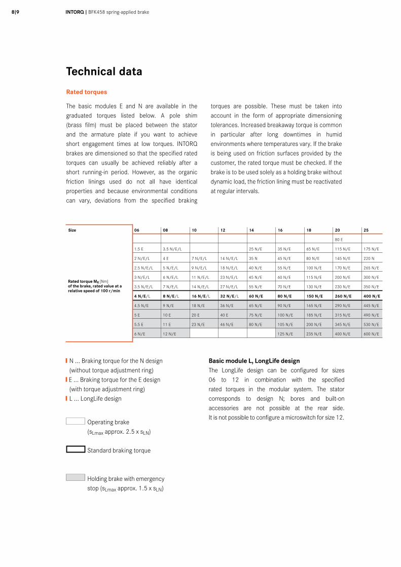
Rated torques
The basic modules E and N are available in the graduated torques listed below. A pole shim (brass film) must be placed between the stator and the armature plate if you want to achieve short engagement times at low torques. INTORQ brakes are dimensioned so that the specified rated torques can usually be achieved reliably after a short running-in period. However, as the organic friction linings used do not all have identical properties and because environmental conditions can vary, deviations from the specified braking
torques are possible. These must be taken into account in the form of appropriate dimensioning tolerances. Increased breakaway torque is common in particular after long downtimes in humid environments where temperatures vary. If the brake is being used on friction surfaces provided by the customer, the rated torque must be checked. If the brake is to be used solely as a holding brake without dynamic load, the friction lining must be reactivated at regular intervals.
Size 06 08 10 12 14 16 18 20 25
80 E
1.5 E 3.5 N/E/L 25 N/E 35 N/E 65 N/E 115 N/E 175 N/E
2 N/E/L 4 E 7 N/E/L 14 N/E/L 35 N 45 N/E 80 N/E 145 N/E 220 N
2.5 N/E/L 5 N/E/L 9 N/E/L 18 N/E/L 40 N/E 55 N/E 100 N/E 170 N/E 265 N/E
3 N/E/L 6 N/E/L 11 N/E/L 23 N/E/L 45 N/E 60 N/E 115 N/E 200 N/E 300 N/E
3.5 N/E/L 7 N/E/L 14 N/E/L 27 N/E/L 55 N/E 70 N/E 130 N/E 230 N/E 350 N/E
4 N/E/L 8 N/E/L 16 N/E/L 32 N/E/L 60 N/E 80 N/E 150 N/E 260 N/E 400 N/E
4.5 N/E 9 N/E 18 N/E 36 N/E 65 N/E 90 N/E 165 N/E 290 N/E 445 N/E
5 E 10 E 20 E 40 E 75 N/E 100 N/E 185 N/E 315 N/E 490 N/E
5.5 E 11 E 23 N/E 46 N/E 80 N/E 105 N/E 200 N/E 345 N/E 530 N/E
6 N/E 12 N/E 125 N/E 235 N/E 400 N/E 600 N/E
Operating brake (sLmax approx. 2.5 x sLN)
Standard braking torque
Holding brake with emergency stop (sLmax approx. 1.5 x sLN)
❙ N ... Braking torque for the N design (without torque adjustment ring) ❙ E ... Braking torque for the E design (with torque adjustment ring)❙ L ... LongLife design
Rated torque MK [Nm] of the brake, rated value at a relative speed of 100 r/min
Basic module L, LongLife designThe LongLife design can be configured for sizes 06 to 12 in combination with the specified rated torques in the modular system. The stator corresponds to design N; bores and built-on accessories are not possible at the rear side. It is not possible to configure a microswitch for size 12.
Size 06 08 10 12 14 16 18 20 25
Torque reduction per detent position [Nm] 0.2 0.35 0.8 1.3 1.7 1.6 3.6 5.6 6.2
Basic module E, reduced rated torqueThe rated torque on basic module E can be reduced using the torque adjustment ring located in the stator. The torque adjustment ring may only be unscrewed to a maximum dimension of h1max (see table on page 11).
It should be noted that the engagement and disengagement times change in accordance with the rated torque. Torque reduction is independent of the rated torque used.
Friction lining variants
Standard and wear-resistant linings
The listed torque ratings and permissible friction work can be combined with any of the brake design options. The catalogue variants are available from a quantity of 1 up to series production levels.
ST (Standard)❙ For universal use❙ Large speed range❙ Short run-in process required❙ Can be used as holding brakes or operating brakes
WR (wear-resistant)❙ Long service life❙ Can be used in standard applications ❙ Restricted maximum speed ❙ Short run-in process required❙ Best for use as a an operating brake
Project solutions
For project solutions INTORQ develops customised series production products on the basis of the customer’s technical specifications. The following friction lining qualities are available for project solutions in addition to the catalogue variants:
HFC (high friction coefficient)❙ For higher braking torques ❙ For use as a holding brake ❙ Short run-in process required
HT (high temperature)❙ Friction lining resistant to high temperatures to allow friction work up to a factor of 5 (compared with the standard aluminium rotor)❙ Stable static torque❙ Resistant to the effects of dampness and humidity
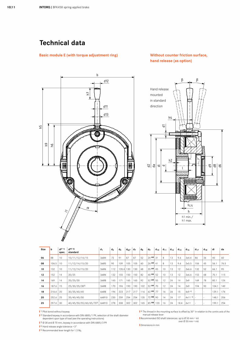
INTORQ I BFK458 spring-applied brake10I11
Technical data
❙ 1) Pilot bored without keyway
❙ 2) Standard keyway in accordance with DIN 6885/1 P9, selection of the shaft diameter dependent upon type of load (see the operating instructions)
❙ 3) Ø 38 and Ø 70 mm, keyway in accordance with DIN 6885/3 P9
❙ 4) Hand release angle tolerance +3°
❙ 5) Recommended lever length for 1.5 MK
❙ 6) The thread in the mounting surface is offset by 30° in relation to the centre axis of the manual release lever
❙ Recommended ISO shaft tolerances: up to Ø 50 mm = k6 over Ø 50 mm = m6
❙ Dimensions in mm
Size b dJ7 1) dH7 2) d1 d2 d5 d6j7 d7 d8 d9 d10 d11 d12 d13 d16 d17 d18 di da spec. standard
06 88 10 10/11/12/14/15 3xM4 72 91 87 87 52 24 H9 31 8 13 9.6 3x4.4 86 36 40 60
08 106.5 10 11/12/14/15/20 3xM5 90 109 105 105 60 26 H9 41 8 13 9.6 3x5.5 106 45 56.1 76.5
10 132 10 11/12/14/15/20 3xM6 112 135.4 130 130 68 35 H9 45 10 13 12 3x6.6 132 52 66.1 95
12 152 14 20/25 3xM6 132 155 150 150 82 40 H9 52 10 13 12 3x6.6 153 68 70.1 115
14 169 14 20/25/30 3xM8 145 171 165 165 92 52 H9 55 12 24 14 3x9 169 78 80.1 124
16 187.6 15 25/30/35/383) 3xM8 170 196 190 190 102 52 H9 70 12 24 14 3x9 194 90 104.1 149
18 218.6 20 30/35/40/45 6xM8 196 223 217 217 116 62 H9 77 14 24 15 4x9 6) - - 129.1 174
20 252.6 25 35/40/45/50 6xM10 230 259 254 254 135 72 H8 90 14 24 17 4x11 6) - - 148.1 206
25 297.6 30 40/45/50/55/60/65/703) 6xM10 278 308 302 302 165 85 H8 120 16 24 18.4 6x11 - - 199.1 254
Basic module E (with torque adjustment ring)
Gr. b d J7 vorg. d H7 Standard d1 d2 d5 d6 j7 d7 d8 d9 H9 d10 d11 d12 d13 d16 d17 d18 di da h h1 min h1max h2 h3 h4 h5 standard h5 max h6 h7 h8 h9 h11 l l1 SLN a a a a β β β β
+5° +5° +5° +5° Gr.
06 88 10 10/11/12/14/15 3xM4 72 91 87 87 52 24 31 8 13 9,6 3x4,4 86 36 40 60 36,3 39,3 43,2 1 6 15,8 107 - 54 23 32,8 56 1,5 18 400 0,2 25° 10° 0608 106,5 10 11/12/14/15/20 3xM5 90 109 105 105 60 26 41 8 13 9,6 3x5,5 106 45 56,1 76,5 42,8 46,8 50,8 1 7 16,3 116 - 63 23 41,3 65 1,5 20 400 0,2 25° 10° 0810 132 10 11/12/14/15/20 3xM6 112 135,4 130 130 68 35 45 10 13 12 3x6,6 132 52 66,1 95 48,4 52,4 55,9 2 9 27,4 132 - 73,3 23 42,4 77,8 1,5 20 400 0,2 25° 10° 1012 152 14 20/25 3xM6 132 155 150 150 82 40 52 10 13 12 3x6,6 153 68 70,1 115 54,9 58,9 67,5 2 9 29,4 161 - 85 23 47,4 88 1,5 25 400 0,3 25° 10° 1214 169 14 20/25/30 3xM8 145 171 165 165 92 52 55 12 24 14 3x9 169 78 80,1 124 66,3 71,3 77,3 2 11 33,8 195 - 97,9 32 50 101 1,5 30 400 0,3 25° 10° 1416 187,6 15 25/30/35/38 3xM8 170 196 190 190 102 52 70 12 24 14 3x9 194 90 104,1 149 72,5 77,5 85,5 2,25 11 37 240 - 111 32 53,5 114 1,5 30 600 0,3 25° 10° 1618 218,6 20 30/35/40/45 6xM8 196 223 217 217 116 62 77 14 24 15 4x9 - - 129,4 174 83,1 89,1 97,1 3 11 41,6 279 394 125 32 59,1 128 - 35 600 0,4 25° 10° 1820 252,6 25 35/40/45/50 6xM10 230 259 254 254 135 72 90 14 24 17 4x11 - - 148,1 206 97,6 104,6 114,6 3,5 11 48,1 319 416 146 32 68,6 148,5 - 40 600 0,4 25° 10° 2025 297,6 30 40/45/50/55/60/65/70 6xM10 278 308 302 302 180 85 120 16 24 18,4 6x11 - - 199,1 254 106,7 115,7 127,7 4,5 12,5 57,7 445 501 170 32 88,7 175 - 50 600 0,5 25° 10° 25
5020
1030
40m
m0
Schu
tzve
rmer
k IS
O 1
6016
bea
chte
n. C
opyr
ight
rese
rved
.
1 2 3 4 5 6 7 8 9 10 11 12
A
B
C
D
E
F
G
H
1 2 3 4 5 6 7 8 9 10 11 12
A
B
C
D
E
F
G
H
Ind./ Anz./ind. quan.
Änder-Nr./revision no.
Datum/date
Name/name
Datum/date Name/name
Bea/drn
Gepr/chkd
Norm/appr
Datei/file
Benennung/name of drawing
Zeichnungsnummer/drawing no.
Ersatz fuer/back-up for
Blatt/sheetCAD
M14.0271_BFK458-06...25E_Standard.iami
StrateDittrich
01.11.201201.11.2012
Maßblatt BFK458-EStandardausführung / Baugröße 06 - 25
M14.0271Zeichnung gleicher Nr. vom 02.04.1998
14
5 - xxxxxx 01.11.2012 STR
aaaa
β β
β β
Without counter friction surface,hand release (as option)
Hand release
mounted
in standard
direction
Gr. b d J7 vorg. d H7 Standard d1 d2 d5 d6 j7 d7 d8 d9 H9 d10 d11 d12 d13 d16 d17 d18 di da h h1 min h1max h2 h3 h4 h5 standard h5 max h6 h7 h8 h9 h11 l l1 SLN a a a a β β β β
+5° +5° +5° +5° Gr.
06 88 10 10/11/12/14/15 3xM4 72 91 87 87 52 24 31 8 13 9,6 3x4,4 86 36 40 60 36,3 39,3 43,2 1 6 15,8 107 - 54 23 32,8 56 1,5 18 400 0,2 25° 10° 0608 106,5 10 11/12/14/15/20 3xM5 90 109 105 105 60 26 41 8 13 9,6 3x5,5 106 45 56,1 76,5 42,8 46,8 50,8 1 7 16,3 116 - 63 23 41,3 65 1,5 20 400 0,2 25° 10° 0810 132 10 11/12/14/15/20 3xM6 112 135,4 130 130 68 35 45 10 13 12 3x6,6 132 52 66,1 95 48,4 52,4 55,9 2 9 27,4 132 - 73,3 23 42,4 77,8 1,5 20 400 0,2 25° 10° 1012 152 14 20/25 3xM6 132 155 150 150 82 40 52 10 13 12 3x6,6 153 68 70,1 115 54,9 58,9 67,5 2 9 29,4 161 - 85 23 47,4 88 1,5 25 400 0,3 25° 10° 1214 169 14 20/25/30 3xM8 145 171 165 165 92 52 55 12 24 14 3x9 169 78 80,1 124 66,3 71,3 77,3 2 11 33,8 195 - 97,9 32 50 101 1,5 30 400 0,3 25° 10° 1416 187,6 15 25/30/35/38 3xM8 170 196 190 190 102 52 70 12 24 14 3x9 194 90 104,1 149 72,5 77,5 85,5 2,25 11 37 240 - 111 32 53,5 114 1,5 30 600 0,3 25° 10° 1618 218,6 20 30/35/40/45 6xM8 196 223 217 217 116 62 77 14 24 15 4x9 - - 129,4 174 83,1 89,1 97,1 3 11 41,6 279 394 125 32 59,1 128 - 35 600 0,4 25° 10° 1820 252,6 25 35/40/45/50 6xM10 230 259 254 254 135 72 90 14 24 17 4x11 - - 148,1 206 97,6 104,6 114,6 3,5 11 48,1 319 416 146 32 68,6 148,5 - 40 600 0,4 25° 10° 2025 297,6 30 40/45/50/55/60/65/70 6xM10 278 308 302 302 180 85 120 16 24 18,4 6x11 - - 199,1 254 106,7 115,7 127,7 4,5 12,5 57,7 445 501 170 32 88,7 175 - 50 600 0,5 25° 10° 25
5020
1030
40m
m0
Schu
tzve
rmer
k IS
O 1
6016
bea
chte
n. C
opyr
ight
rese
rved
.
1 2 3 4 5 6 7 8 9 10 11 12
A
B
C
D
E
F
G
H
1 2 3 4 5 6 7 8 9 10 11 12
A
B
C
D
E
F
G
H
Ind./ Anz./ind. quan.
Änder-Nr./revision no.
Datum/date
Name/name
Datum/date Name/name
Bea/drn
Gepr/chkd
Norm/appr
Datei/file
Benennung/name of drawing
Zeichnungsnummer/drawing no.
Ersatz fuer/back-up for
Blatt/sheetCAD
M14.0271_BFK458-06...25E_Standard.iami
StrateDittrich
01.11.201201.11.2012
Maßblatt BFK458-EStandardausführung / Baugröße 06 - 25
M14.0271Zeichnung gleicher Nr. vom 02.04.1998
14
5 - xxxxxx 01.11.2012 STR
aaaa
β β
β β
Gr. b d J7 vorg. d H7 Standard d1 d2 d5 d6 j7 d7 d8 d9 H9 d10 d11 d12 d13 d16 d17 d18 di da h h1 min h1max h2 h3 h4 h5 standard h5 max h6 h7 h8 h9 h11 l l1 SLN a a a a
β β β β
+5° +5° +5° +5° Gr.
06 88 10 10/11/12/14/15 3xM4 72 91 87 87 52 24 31 8 13 9,6 3x4,4 86 36 40 60 36,3 39,3 43,2 1 6 15,8 107 - 54 23 32,8 56 1,5 18 400 0,2 25° 10° 0608 106,5 10 11/12/14/15/20 3xM5 90 109 105 105 60 26 41 8 13 9,6 3x5,5 106 45 56,1 76,5 42,8 46,8 50,8 1 7 16,3 116 - 63 23 41,3 65 1,5 20 400 0,2 25° 10° 0810 132 10 11/12/14/15/20 3xM6 112 135,4 130 130 68 35 45 10 13 12 3x6,6 132 52 66,1 95 48,4 52,4 55,9 2 9 27,4 132 - 73,3 23 42,4 77,8 1,5 20 400 0,2 25° 10° 1012 152 14 20/25 3xM6 132 155 150 150 82 40 52 10 13 12 3x6,6 153 68 70,1 115 54,9 58,9 67,5 2 9 29,4 161 - 85 23 47,4 88 1,5 25 400 0,3 25° 10° 1214 169 14 20/25/30 3xM8 145 171 165 165 92 52 55 12 24 14 3x9 169 78 80,1 124 66,3 71,3 77,3 2 11 33,8 195 - 97,9 32 50 101 1,5 30 400 0,3 25° 10° 1416 187,6 15 25/30/35/38 3xM8 170 196 190 190 102 52 70 12 24 14 3x9 194 90 104,1 149 72,5 77,5 85,5 2,25 11 37 240 - 111 32 53,5 114 1,5 30 600 0,3 25° 10° 1618 218,6 20 30/35/40/45 6xM8 196 223 217 217 116 62 77 14 24 15 4x9 - - 129,4 174 83,1 89,1 97,1 3 11 41,6 279 394 125 32 59,1 128 - 35 600 0,4 25° 10° 1820 252,6 25 35/40/45/50 6xM10 230 259 254 254 135 72 90 14 24 17 4x11 - - 148,1 206 97,6 104,6 114,6 3,5 11 48,1 319 416 146 32 68,6 148,5 - 40 600 0,4 25° 10° 2025 297,6 30 40/45/50/55/60/65/70 6xM10 278 308 302 302 180 85 120 16 24 18,4 6x11 - - 199,1 254 106,7 115,7 127,7 4,5 12,5 57,7 445 501 170 32 88,7 175 - 50 600 0,5 25° 10° 25
5020
1030
40m
m0
Schu
tzve
rmer
k IS
O 1
6016
bea
chte
n. C
opyr
ight
rese
rved
.
1 2 3 4 5 6 7 8 9 10 11 12
A
B
C
D
E
F
G
H
1 2 3 4 5 6 7 8 9 10 11 12
A
B
C
D
E
F
G
H
Ind./ Anz./ind. quan.
Änder-Nr./revision no.
Datum/date
Name/name
Datum/date Name/name
Bea/drn
Gepr/chkd
Norm/appr
Datei/file
Benennung/name of drawing
Zeichnungsnummer/drawing no.
Ersatz fuer/back-up for
Blatt/sheetCAD
M14.0271_BFK458-06...25E_Standard.iami
StrateDittrich
01.11.201201.11.2012
Maßblatt BFK458-EStandardausführung / Baugröße 06 - 25
M14.0271Zeichnung gleicher Nr. vom 02.04.1998
14
5 - xxxxxx 01.11.2012 STR
aaaa
β β
β β
h1 min./h1 max.
sLN
Gr. b d J7 vorg. d H7 Standard d1 d2 d5 d6 j7 d7 d8 d9 H9 d10 d11 d12 d13 d16 d17 d18 di da h h1 min h1max h2 h3 h4 h5 standard h5 max h6 h7 h8 h9 h11 l l1 SLN a a a a β β β β
+5° +5° +5° +5° Gr.
06 88 10 10/11/12/14/15 3xM4 72 91 87 87 52 24 31 8 13 9,6 3x4,4 86 36 40 60 36,3 39,3 43,2 1 6 15,8 107 - 54 23 32,8 56 1,5 18 400 0,2 25° 10° 0608 106,5 10 11/12/14/15/20 3xM5 90 109 105 105 60 26 41 8 13 9,6 3x5,5 106 45 56,1 76,5 42,8 46,8 50,8 1 7 16,3 116 - 63 23 41,3 65 1,5 20 400 0,2 25° 10° 0810 132 10 11/12/14/15/20 3xM6 112 135,4 130 130 68 35 45 10 13 12 3x6,6 132 52 66,1 95 48,4 52,4 55,9 2 9 27,4 132 - 73,3 23 42,4 77,8 1,5 20 400 0,2 25° 10° 1012 152 14 20/25 3xM6 132 155 150 150 82 40 52 10 13 12 3x6,6 153 68 70,1 115 54,9 58,9 67,5 2 9 29,4 161 - 85 23 47,4 88 1,5 25 400 0,3 25° 10° 1214 169 14 20/25/30 3xM8 145 171 165 165 92 52 55 12 24 14 3x9 169 78 80,1 124 66,3 71,3 77,3 2 11 33,8 195 - 97,9 32 50 101 1,5 30 400 0,3 25° 10° 1416 187,6 15 25/30/35/38 3xM8 170 196 190 190 102 52 70 12 24 14 3x9 194 90 104,1 149 72,5 77,5 85,5 2,25 11 37 240 - 111 32 53,5 114 1,5 30 600 0,3 25° 10° 1618 218,6 20 30/35/40/45 6xM8 196 223 217 217 116 62 77 14 24 15 4x9 - - 129,4 174 83,1 89,1 97,1 3 11 41,6 279 394 125 32 59,1 128 - 35 600 0,4 25° 10° 1820 252,6 25 35/40/45/50 6xM10 230 259 254 254 135 72 90 14 24 17 4x11 - - 148,1 206 97,6 104,6 114,6 3,5 11 48,1 319 416 146 32 68,6 148,5 - 40 600 0,4 25° 10° 2025 297,6 30 40/45/50/55/60/65/70 6xM10 278 308 302 302 180 85 120 16 24 18,4 6x11 - - 199,1 254 106,7 115,7 127,7 4,5 12,5 57,7 445 501 170 32 88,7 175 - 50 600 0,5 25° 10° 25
5020
1030
40m
m0
Schu
tzve
rmer
k IS
O 1
6016
bea
chte
n. C
opyr
ight
rese
rved
.
1 2 3 4 5 6 7 8 9 10 11 12
A
B
C
D
E
F
G
H
1 2 3 4 5 6 7 8 9 10 11 12
A
B
C
D
E
F
G
H
Ind./ Anz./ind. quan.
Änder-Nr./revision no.
Datum/date
Name/name
Datum/date Name/name
Bea/drn
Gepr/chkd
Norm/appr
Datei/file
Benennung/name of drawing
Zeichnungsnummer/drawing no.
Ersatz fuer/back-up for
Blatt/sheetCAD
M14.0271_BFK458-06...25E_Standard.iami
StrateDittrich
01.11.201201.11.2012
Maßblatt BFK458-EStandardausführung / Baugröße 06 - 25
M14.0271Zeichnung gleicher Nr. vom 02.04.1998
14
5 - xxxxxx 01.11.2012 STR
aaaa
β β
β β
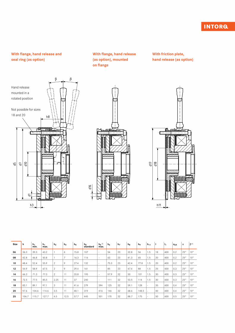
With flange, hand release (as option), mounted on flange
With friction plate,hand release (as option)
With flange, hand release and seal ring (as option)
Hand release
mounted in a
rotated position
Not possible for sizes
18 and 20
Size h h1 h1 h2 h3 h4 h5 h5 5) h6 h7 h8 h9 h11 l l1 sLN a b 4)
min. max. standard max.
06 36.3 39.3 43.2 1 6 15.8 107 - 54 23 32.8 56 1.5 18 400 0.2 25° 10°
08 42.8 46.8 50.8 1 7 16.3 116 – 63 23 41.3 65 1.5 20 400 0.2 25° 10°
10 48.4 52.4 55.9 2 9 27.4 132 - 73.3 23 42.4 77.8 1.5 20 400 0.2 25° 10°
12 54.9 58.9 67.5 2 9 29.4 161 - 85 23 47.4 88 1.5 25 400 0.3 25° 10°
14 66.3 71.3 77.3 2 11 33.8 195 – 97.9 32 50 101 1.5 30 400 0.3 25° 10°
16 72.5 77.5 85.5 2.25 11 37 240 – 111 32 53.5 114 1.5 30 600 0.3 25° 10°
18 83.1 89.1 97.1 3 11 41.6 279 394 125 32 59.1 128 - 35 600 0.4 25° 10°
20 97.6 104.6 114.6 3.5 11 48.1 319 416 146 32 68.6 148.5 - 40 600 0.4 25° 10°
25 106.7 115.7 127.7 4.5 12.5 57.7 445 501 170 32 88.7 175 - 50 600 0.5 25° 10°
INTORQ I BFK458 spring-applied brake12I13
Technical data
Basic module N (without torque adjustment ring)
Gr. b d J7 vorg. d H7 Standard d1 d2 d3 H7 d5 d6 j7 d7 d10 d11 d12 d13 d14 d15 d16 d17 d18 di da h h2 h3 h4 h5 standard h5 max h6 h7 h8 h9 h11 l l1 SLN a a a a β β β β
+5° +5° +5° +5° Gr.
06 88 10 10/11/12/14/15 3xM4 72 25 91 87 87 31 8 13 9,6 4xM4 37,7 3x4,4 86 36 40 60 36,3 1 6 15,8 107 - 54 23 32,8 56 1,5 18 400 0,2 25° 1 0° 0608 106,5 10 11/12/14/15/20 3xM5 90 32 109 105 105 41 8 13 9,6 4xM5 49 3x5,5 106 45 56,1 76,5 42,8 1 7 16,3 116 - 63 23 41,3 65 1,5 20 400 0,2 25° 10° 0810 132 10 11/12/14/15/20 3xM6 112 42 135 130 130 45 10 13 12 4xM5 54 3x6,6 132 52 66,1 95 48,4 2 9 27,4 132 - 73,3 23 42,4 77,8 1,5 20 400 0,2 25° 10° 1012 152 14 20/25 3xM6 132 50 155 150 150 52 10 13 12 4xM5 64 3x6,6 153 68 70,1 115 54,9 2 9 29,4 161 - 85 23 47,4 88 1,5 25 400 0,3 25° 10° 1214 169 14 20/25/30 3xM8 145 60 171 165 165 55 12 24 14 4xM6 75 3x9 169 78 80,1 124 66,3 2 11 33,8 195 - 97,9 32 50 101 1,5 30 400 0,3 25° 10° 1416 187,6 15 25/30/35/38 3xM8 170 68 196 190 190 70 12 24 14 4xM6 85 3x9 194 90 104,1 149 72,5 2,25 11 37 240 - 111 32 53,5 114 1,5 30 600 0,3 25° 10° 1618 218,6 20 30/35/40/45 6xM8 196 75 223 217 217 77 14 24 15 4xM8 95 4x9 - - 129,4 174 83,1 3 11 41,6 279 394 125 32 59,1 128 - 35 600 0,4 25° 10° 1820 252,6 25 35/40/45/50 6xM10 230 85 259 254 254 90 14 24 17 4xM10 110 4x11 - - 148,1 206 97,6 3,5 11 48,1 319 416 146 32 68,6 148,5 - 40 600 0,4 25° 10° 2025 297,6 30 40/45/50/55/60/65/70 6xM10 278 115 308 302 302 120 16 24 18,4 4xM10 140 6x11 - - 199,1 254 106,7 4,5 12,5 57,7 445 501 170 32 88,7 175 - 50 600 0,5 25° 10° 25
Ind./ Anz./ind. quan.
Änder-Nr./revision no.
Datum/date
Name/name
Datum/date Name/name
Bea/drn
Gepr/chkd
Norm/appr
Datei/file
Benennung/name of drawing
Zeichnungsnummer/drawing no.
Ersatz fuer/back-up for
Blatt/sheetCAD
M14.0271_BFK458-06...25N_Standard.iami
StrateDittrich
01.11.201201.11.2012
Maßblatt BFK458-NStandardausführung - Baugröße 06 - 25
M14.0271Zeichnung gleicher Nr. vom 02.04.1998
24
5 - xxxxxx 01.11.2012 STR
5020
1030
40m
m0
Schu
tzve
rmer
k IS
O 1
6016
bea
chte
n. C
opyr
ight
rese
rved
.
1 2 3 4 5 6 7 8 9 10 11 12
A
B
C
D
E
F
G
H
1 2 3 4 5 6 7 8 9 10 11 12
A
B
C
D
E
F
G
H
aaaa
β β β β
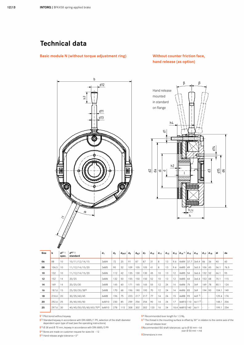
❙ 1) Pilot bored without keyway
❙ 2) Standard keyway in accordance with DIN 6885/1 P9, selection of the shaft diameter dependent upon type of load (see the operating instructions)
❙ 3) Ø 38 and Ø 70 mm, keyway in accordance with DIN 6885/3 P9
❙ 4) Bores are made on customer request for sizes 06 – 12
❙ 5) Hand release angle tolerance +3°
❙ 6) Recommended lever length for 1.5 MK
❙ 7) The thread in the mounting surface is offset by 30° in relation to the centre axis of the
manual release lever❙ Recommended ISO shaft tolerances: up to Ø 50 mm = k6
over Ø 50 mm = m6
❙ Dimensions in mm
Size b dJ7 1) dH7 2) d1 d2 d3H7 d5 d6j7 d7 d10 d11 d12 d13 d14 4) d15 d16 d17 d18 di da spec. standard
06 88 10 10/11/12/14/15 3xM4 72 25 91 87 87 31 8 13 9.6 4xM4 37.7 3x4.4 86 36 40 60
08 106.5 10 11/12/14/15/20 3xM5 90 32 109 105 105 41 8 13 9.6 4xM5 49 3x5.5 106 45 56.1 76.5
10 132 10 11/12/14/15/20 3xM6 112 42 135 130 130 45 10 13 12 4xM5 54 3x6.6 132 52 66.1 95
12 152 14 20/25 3xM6 132 50 155 150 150 52 10 13 12 4xM5 64 3x6.6 153 68 70.1 115
14 169 14 20/25/30 3xM8 145 60 171 165 165 55 12 24 14 4xM6 75 3x9 169 78 80.1 124
16 187.6 15 25/30/35/383) 3xM8 170 68 196 190 190 70 12 24 14 4xM6 85 3x9 194 90 104.1 149
18 218.6 20 30/35/40/45 6xM8 196 75 223 217 217 77 14 24 15 4xM8 95 4x9 7) - - 129.4 174
20 252.6 25 35/40/45/50 6xM10 230 85 259 254 254 90 14 24 17 4xM10 110 4x117) - - 148.1 206
25 297.6 30 40/45/50/55/60/65/703) 6xM10 278 115 308 302 302 120 16 24 18.4 4xM10 140 6x11 - - 199.1 254
Without counter friction face,hand release (as option)
Hand release
mounted
in standard
on flange
sLN
Size h h2 h3 h4 h5 h56) h6 h7 h8 h9 h11 l l1 sLN a b 5)
standard max.
06 36.3 1 6 15.8 107 – 54 23 32.8 56 1.5 18 400 0.2 25° 10°
08 42.8 1 7 16.3 116 – 63 23 41.3 65 1.5 20 400 0.2 25° 10°
10 48.4 2 9 27.4 132 – 73.3 23 42.4 77.8 1.5 20 400 0.2 25° 10°
12 54.9 2 9 29.4 161 – 85 23 47.4 88 1.5 25 400 0.3 25° 10°
14 66.3 2 11 33.8 195 – 97.9 32 50 101 1.5 30 400 0.3 25° 10°
16 72.5 2.25 11 37 240 – 111 32 53.5 114 1.5 30 600 0.3 25° 10°
18 83.1 3 11 41.6 279 394 125 32 59.1 128 - 35 600 0.4 25° 10°
20 97.6 3.5 11 48.1 319 416 146 32 68.6 148.5 - 40 600 0.4 25° 10°
25 106.7 4.5 12.5 57.7 445 501 170 32 88.7 175 - 50 600 0.5 25° 10°
Gr. b d J7 vorg. d H7 Standard d1 d2 d3 H7 d5 d6 j7 d7 d10 d11 d12 d13 d14 d15 d16 d17 d18 di da h h2 h3 h4 h5 standard h5 max h6 h7 h8 h9 h11 l l1 SLN a a a a β β β β
+5° +5° +5° +5° Gr.
06 88 10 10/11/12/14/15 3xM4 72 25 91 87 87 31 8 13 9,6 4xM4 37,7 3x4,4 86 36 40 60 36,3 1 6 15,8 107 - 54 23 32,8 56 1,5 18 400 0,2 25° 1 0° 0608 106,5 10 11/12/14/15/20 3xM5 90 32 109 105 105 41 8 13 9,6 4xM5 49 3x5,5 106 45 56,1 76,5 42,8 1 7 16,3 116 - 63 23 41,3 65 1,5 20 400 0,2 25° 10° 0810 132 10 11/12/14/15/20 3xM6 112 42 135 130 130 45 10 13 12 4xM5 54 3x6,6 132 52 66,1 95 48,4 2 9 27,4 132 - 73,3 23 42,4 77,8 1,5 20 400 0,2 25° 10° 1012 152 14 20/25 3xM6 132 50 155 150 150 52 10 13 12 4xM5 64 3x6,6 153 68 70,1 115 54,9 2 9 29,4 161 - 85 23 47,4 88 1,5 25 400 0,3 25° 10° 1214 169 14 20/25/30 3xM8 145 60 171 165 165 55 12 24 14 4xM6 75 3x9 169 78 80,1 124 66,3 2 11 33,8 195 - 97,9 32 50 101 1,5 30 400 0,3 25° 10° 1416 187,6 15 25/30/35/38 3xM8 170 68 196 190 190 70 12 24 14 4xM6 85 3x9 194 90 104,1 149 72,5 2,25 11 37 240 - 111 32 53,5 114 1,5 30 600 0,3 25° 10° 1618 218,6 20 30/35/40/45 6xM8 196 75 223 217 217 77 14 24 15 4xM8 95 4x9 - - 129,4 174 83,1 3 11 41,6 279 394 125 32 59,1 128 - 35 600 0,4 25° 10° 1820 252,6 25 35/40/45/50 6xM10 230 85 259 254 254 90 14 24 17 4xM10 110 4x11 - - 148,1 206 97,6 3,5 11 48,1 319 416 146 32 68,6 148,5 - 40 600 0,4 25° 10° 2025 297,6 30 40/45/50/55/60/65/70 6xM10 278 115 308 302 302 120 16 24 18,4 4xM10 140 6x11 - - 199,1 254 106,7 4,5 12,5 57,7 445 501 170 32 88,7 175 - 50 600 0,5 25° 10° 25
Ind./ Anz./ind. quan.
Änder-Nr./revision no.
Datum/date
Name/name
Datum/date Name/name
Bea/drn
Gepr/chkd
Norm/appr
Datei/file
Benennung/name of drawing
Zeichnungsnummer/drawing no.
Ersatz fuer/back-up for
Blatt/sheetCAD
M14.0271_BFK458-06...25N_Standard.iami
StrateDittrich
01.11.201201.11.2012
Maßblatt BFK458-NStandardausführung - Baugröße 06 - 25
M14.0271Zeichnung gleicher Nr. vom 02.04.1998
24
5 - xxxxxx 01.11.2012 STR
5020
1030
40m
m0
Schu
tzve
rmer
k IS
O 1
6016
bea
chte
n. C
opyr
ight
rese
rved
.
1 2 3 4 5 6 7 8 9 10 11 12
A
B
C
D
E
F
G
H
1 2 3 4 5 6 7 8 9 10 11 12
A
B
C
D
E
F
G
H
aaaa
β β β β
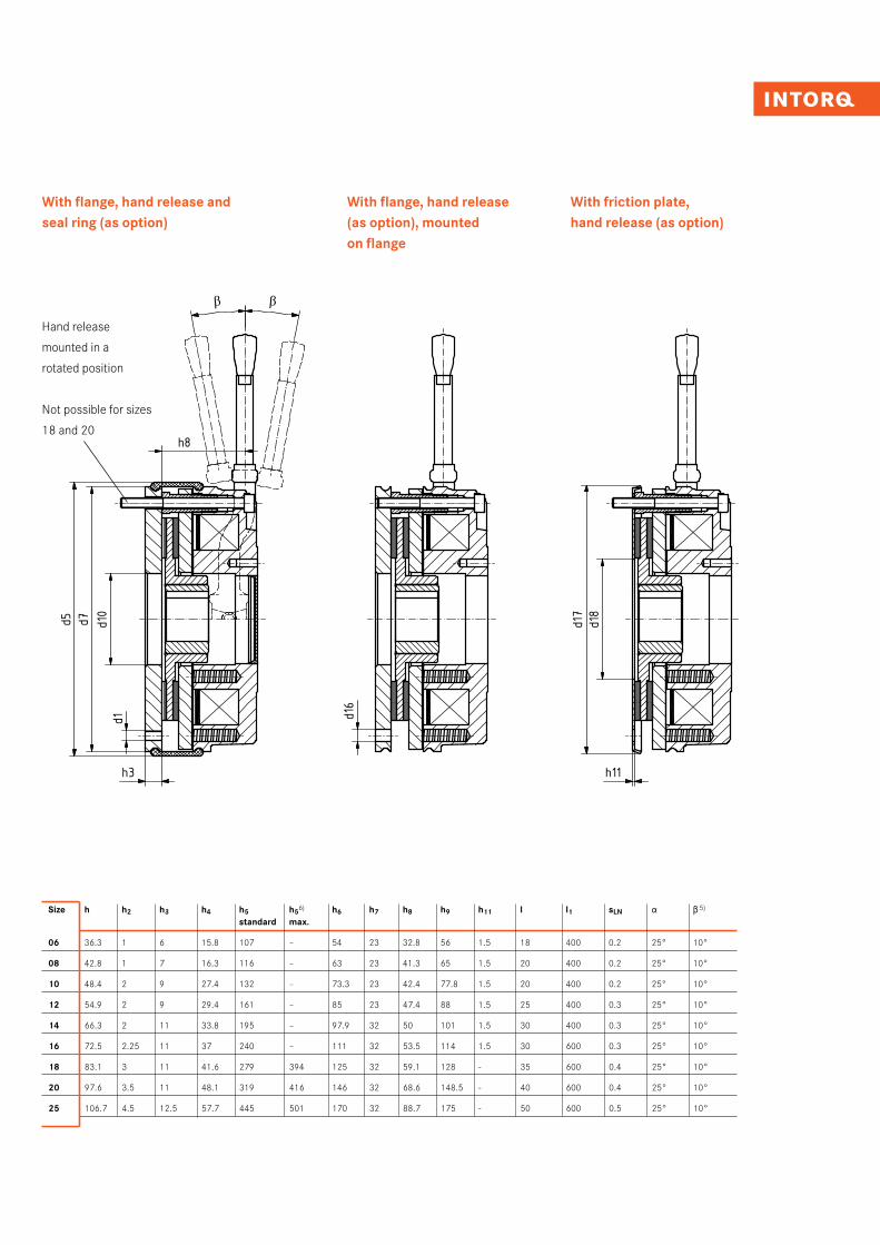
With flange, hand release (as option), mounted on flange
With friction plate,hand release (as option)
With flange, hand release and seal ring (as option)
Hand release
mounted in a
rotated position
Not possible for sizes
18 and 20
INTORQ I BFK458 spring-applied brake14I15
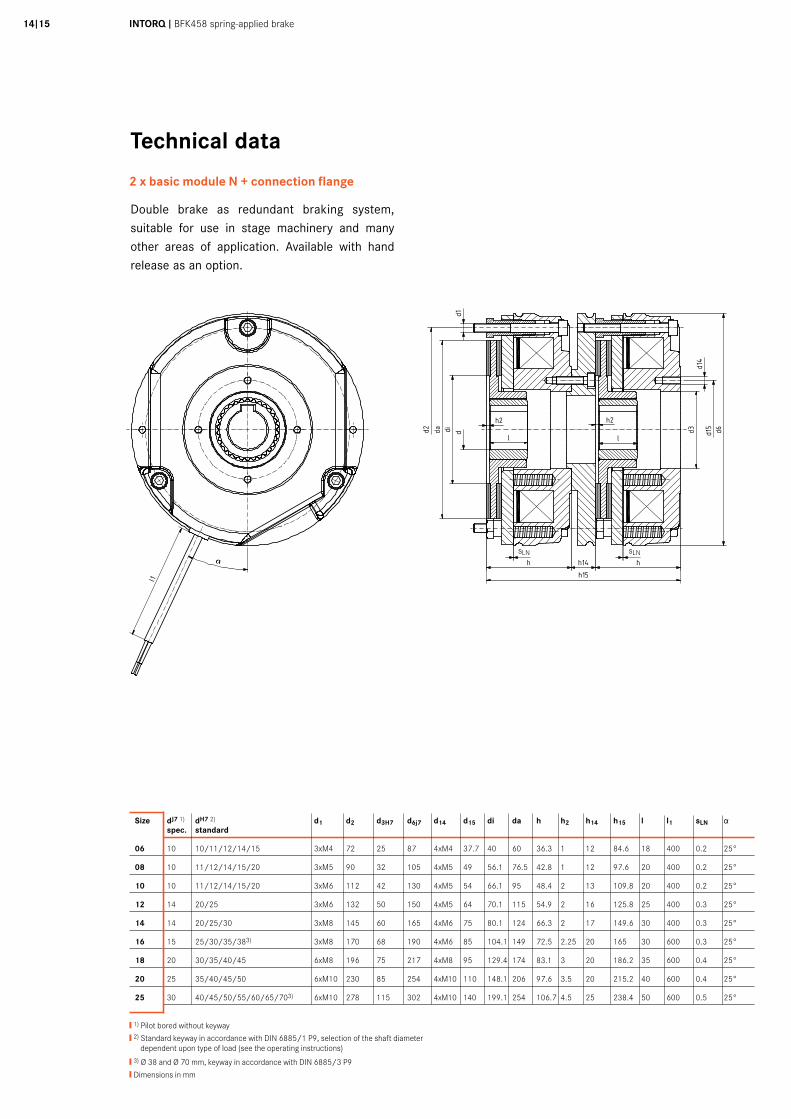
Technical data
2 x basic module N + connection flange
Double brake as redundant braking system, suitable for use in stage machinery and many other areas of application. Available with hand release as an option.
Gr. d J7 vorg. d H7 Standard d1 d2 d3 H7 d6 j7 d14 d15 di da h h2 h14 h15 l l1 SLN Gr.
06 10 10/11/12/14/15 3xM4 72 25 87 4xM4 37,7 40 60 36,3 1 12 84,6 18 400 0,2 25° 0608 10 11/12/14/15/20 3xM5 90 32 105 4xM5 49 56,1 76,5 42,8 1 12 97,6 20 400 0,2 25° 0810 10 11/12/14/15/20 3xM6 112 42 130 4xM5 54 66,1 95 48,4 2 13 109,8 20 400 0,2 25° 1012 14 20/25 3xM6 132 50 150 4xM5 64 70,1 115 54,9 2 16 125,8 25 400 0,3 25° 1214 14 20/25/30 3xM8 145 60 165 4xM6 75 80,1 124 66,3 2 17 149,6 30 400 0,3 25° 1416 15 25/30/35/38 3xM8 170 68 190 4xM6 85 104,1 149 72,5 2,25 20 165 30 600 0,3 25° 1618 20 30/35/40/45 6xM8 196 75 217 4xM8 95 129,4 174 83,1 3 20 186,2 35 600 0,4 25° 1820 25 35/40/45/50 6xM10 230 85 254 4xM10 110 148,1 206 97,6 3,5 20 215,2 40 600 0,4 25° 2025 30 40/45/50/55/60/65/70 6xM10 278 115 302 4xM10 140 199,1 254 106,7 4,5 25 238,4 50 600 0,5 25° 25
5020
1030
40m
m0
Schu
tzve
rmer
k IS
O 1
6016
bea
chte
n. C
opyr
ight
rese
rved
.
1 2 3 4 5 6 7 8 9 10 11 12
A
B
C
D
E
F
G
H
1 2 3 4 5 6 7 8 9 10 11 12
A
B
C
D
E
F
G
H
Ind./ Anz./ind. quan.
Änder-Nr./revision no.
Datum/date
Name/name
Datum/date Name/name
Bea/drn
Gepr/chkd
Norm/appr
Datei/file
Benennung/name of drawing
Zeichnungsnummer/drawing no.
Ersatz fuer/back-up for
Blatt/sheetCAD
M14.0270_BFK458-06...25_Doppelbremse.iami
StrateDittrich
02.11.201202.11.2012 Maßblatt BFK458
Doppelbremse / Baugröße 06 - 25
M14.0270Zeichnung gleicher Nr. vom 18.09.2007
12
5 - xxxxxx 02.11.2012 STR
❙ 1) Pilot bored without keyway
❙ 2) Standard keyway in accordance with DIN 6885/1 P9, selection of the shaft diameter dependent upon type of load (see the operating instructions)
❙ 3) Ø 38 and Ø 70 mm, keyway in accordance with DIN 6885/3 P9
❙ Dimensions in mm
Size dJ7 1) dH7 2) d1 d2 d3H7 d6j7 d14 d15 di da h h2 h14 h15 l l1 sLN a spec. standard
06 10 10/11/12/14/15 3xM4 72 25 87 4xM4 37.7 40 60 36.3 1 12 84.6 18 400 0.2 25°
08 10 11/12/14/15/20 3xM5 90 32 105 4xM5 49 56.1 76.5 42.8 1 12 97.6 20 400 0.2 25°
10 10 11/12/14/15/20 3xM6 112 42 130 4xM5 54 66.1 95 48.4 2 13 109.8 20 400 0.2 25°
12 14 20/25 3xM6 132 50 150 4xM5 64 70.1 115 54.9 2 16 125.8 25 400 0.3 25°
14 14 20/25/30 3xM8 145 60 165 4xM6 75 80.1 124 66.3 2 17 149.6 30 400 0.3 25°
16 15 25/30/35/383) 3xM8 170 68 190 4xM6 85 104.1 149 72.5 2.25 20 165 30 600 0.3 25°
18 20 30/35/40/45 6xM8 196 75 217 4xM8 95 129.4 174 83.1 3 20 186.2 35 600 0.4 25°
20 25 35/40/45/50 6xM10 230 85 254 4xM10 110 148.1 206 97.6 3.5 20 215.2 40 600 0.4 25°
25 30 40/45/50/55/60/65/703) 6xM10 278 115 302 4xM10 140 199.1 254 106.7 4.5 25 238.4 50 600 0.5 25°
sLN sLN
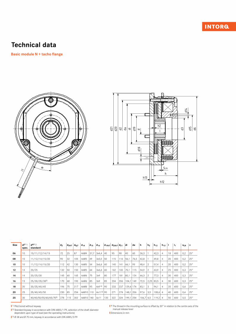
Technical dataBasic module N + tacho flange
❙ 1) Pilot bored without keyway
❙ 2) Standard keyway in accordance with DIN 6885/1 P9, selection of the shaft diameter dependent upon type of load (see the operating instructions)
❙ 3) Ø 38 and Ø 70 mm, keyway in accordance with DIN 6885/3 P9
❙ 4) The thread in the mounting surface is offset by 30° in relation to the centre axis of the manual release lever
❙ Dimensions in mm
Gr. d J7 vorg. d H7 Standard d1 d2 d3 H7 d6 j7 d14 d15 d19 H7 d20 h7 d21 di da h h2 h12 h13 l l1 SLN Gr.
06 10 10/11/12/14/15 3xM4 72 25 87 4xM4 37,7 40 95 98 40 60 36,3 1 42,3 4 18 400 0,2 25° 0608 10 11/12/14/15/20 3xM5 90 32 105 4xM5 49 50 115 116 56,1 76,5 42,8 1 49,8 4 20 400 0,2 25° 0810 10 11/12/14/15/20 3xM6 112 42 130 4xM5 54 60 140 141 66,1 95 48,4 2 57,4 4 20 400 0,2 25° 1012 14 20/25 3xM6 132 50 150 4xM5 64 60 162 165 70,1 115 54,9 2 63,9 4 25 400 0,3 25° 1214 14 20/25/30 3xM8 145 60 165 4xM6 75 80 177 181 80,1 124 66,3 2 77,3 4 30 400 0,3 25° 1416 15 25/30/35/38 3xM8 170 68 190 4xM6 85 85 204 206 104,1 149 72,5 2,25 83,5 4 30 600 0,3 25° 1618 20 30/35/40/45 4xM8 196 75 217 4xM8 95 90 233 237 129,4 174 83,1 3 94,1 4 35 600 0,4 25° 1820 25 35/40/45/50 4xM10 230 85 254 4xM10 110 90 271 274 148,1 206 97,6 3,5 108,6 4 40 600 0,4 25° 2025 30 40/45/50/55/60/65/70 6xM10 278 115 302 4xM10 140 120 322 324 199,1 254 106,7 4,5 119,2 4 50 600 0,5 25° 25
5020
1030
40m
m0
Schu
tzve
rmer
k IS
O 1
6016
bea
chte
n. C
opyr
ight
rese
rved
.
1 2 3 4 5 6 7 8 9 10 11 12
A
B
C
D
E
F
G
H
1 2 3 4 5 6 7 8 9 10 11 12
A
B
C
D
E
F
G
H
Ind./ Anz./ind. quan.
Änder-Nr./revision no.
Datum/date
Name/name
Datum/date Name/name
Bea/drn
Gepr/chkd
Norm/appr
Datei/file
Benennung/name of drawing
Zeichnungsnummer/drawing no.
Ersatz fuer/back-up for
Blatt/sheetCAD
M14.0269_BFK458-06...25_Tachoflansch.iami
StrateDittrich
02.11.201202.11.2012 Maßblatt BFK458
Tachoausführung / Baugröße 06 - 25
M14.0269Zeichnung gleicher Nr. vom 10.04.1997
12
5 - xxxxxx 02.11.2012 STR
Gr. b d J7 vorg. d H7 Standard d1 d2 d3 H7 d5 d6 j7 d7 d10 d11 d12 d13 d14 d15 d16 d17 d18 di da h h2 h3 h4 h5 standard h5 max h6 h7 h8 h9 h11 l l1 SLN a a a a β β β β
+5° +5° +5° +5° Gr.
06 88 10 10/11/12/14/15 3xM4 72 25 91 87 87 31 8 13 9,6 4xM4 37,7 3x4,4 86 36 40 60 36,3 1 6 15,8 107 - 54 23 32,8 56 1,5 18 400 0,2 25° 1 0° 0608 106,5 10 11/12/14/15/20 3xM5 90 32 109 105 105 41 8 13 9,6 4xM5 49 3x5,5 106 45 56,1 76,5 42,8 1 7 16,3 116 - 63 23 41,3 65 1,5 20 400 0,2 25° 10° 0810 132 10 11/12/14/15/20 3xM6 112 42 135 130 130 45 10 13 12 4xM5 54 3x6,6 132 52 66,1 95 48,4 2 9 27,4 132 - 73,3 23 42,4 77,8 1,5 20 400 0,2 25° 10° 1012 152 14 20/25 3xM6 132 50 155 150 150 52 10 13 12 4xM5 64 3x6,6 153 68 70,1 115 54,9 2 9 29,4 161 - 85 23 47,4 88 1,5 25 400 0,3 25° 10° 1214 169 14 20/25/30 3xM8 145 60 171 165 165 55 12 24 14 4xM6 75 3x9 169 78 80,1 124 66,3 2 11 33,8 195 - 97,9 32 50 101 1,5 30 400 0,3 25° 10° 1416 187,6 15 25/30/35/38 3xM8 170 68 196 190 190 70 12 24 14 4xM6 85 3x9 194 90 104,1 149 72,5 2,25 11 37 240 - 111 32 53,5 114 1,5 30 600 0,3 25° 10° 1618 218,6 20 30/35/40/45 6xM8 196 75 223 217 217 77 14 24 15 4xM8 95 4x9 - - 129,4 174 83,1 3 11 41,6 279 394 125 32 59,1 128 - 35 600 0,4 25° 10° 1820 252,6 25 35/40/45/50 6xM10 230 85 259 254 254 90 14 24 17 4xM10 110 4x11 - - 148,1 206 97,6 3,5 11 48,1 319 416 146 32 68,6 148,5 - 40 600 0,4 25° 10° 2025 297,6 30 40/45/50/55/60/65/70 6xM10 278 115 308 302 302 120 16 24 18,4 4xM10 140 6x11 - - 199,1 254 106,7 4,5 12,5 57,7 445 501 170 32 88,7 175 - 50 600 0,5 25° 10° 25
Ind./ Anz./ind. quan.
Änder-Nr./revision no.
Datum/date
Name/name
Datum/date Name/name
Bea/drn
Gepr/chkd
Norm/appr
Datei/file
Benennung/name of drawing
Zeichnungsnummer/drawing no.
Ersatz fuer/back-up for
Blatt/sheetCAD
M14.0271_BFK458-06...25N_Standard.iami
StrateDittrich
01.11.201201.11.2012
Maßblatt BFK458-NStandardausführung - Baugröße 06 - 25
M14.0271Zeichnung gleicher Nr. vom 02.04.1998
24
5 - xxxxxx 01.11.2012 STR
5020
1030
40m
m0
Schu
tzve
rmer
k IS
O 1
6016
bea
chte
n. C
opyr
ight
rese
rved
.
1 2 3 4 5 6 7 8 9 10 11 12
A
B
C
D
E
F
G
H
1 2 3 4 5 6 7 8 9 10 11 12
A
B
C
D
E
F
G
H
aaaa
β β β β
Size dJ7 1) dH7 2) d2 d3H7 d6j7 d14 d15 d16 d19h7 d20h7 d21 di da h h2 h12 h13 l l1 sLN a spec. standard
06 10 10/11/12/14/15 72 25 87 4xM4 37,7 3x4,4 40 95 98 40 60 36,3 1 42,3 4 18 400 0,2 25°
08 10 11/12/14/15/20 90 32 105 4xM5 49 3x5,5 50 115 116 56,1 76,5 42,8 1 49,8 4 20 400 0,2 25°
10 10 11/12/14/15/20 112 42 130 4xM5 54 3x6,6 60 140 141 66,1 95 48,4 2 57,4 4 20 400 0,2 25°
12 14 20/25 132 50 150 4xM5 64 3x6,6 60 162 165 70,1 115 54,9 2 63,9 4 25 400 0,3 25°
14 14 20/25/30 145 60 165 4xM6 75 3x9 80 177 181 80,1 124 66,3 2 77,3 4 30 400 0,3 25°
16 15 25/30/35/383) 170 68 190 4xM6 85 3x9 85 204 206 104,1 149 72,5 2,25 83,5 4 30 600 0,3 25°
18 20 30/35/40/45 196 75 217 4xM8 95 4x9 4) 90 233 237 129,4 174 83,1 3 94,1 4 35 600 0,4 25°
20 25 35/40/45/50 230 85 254 4xM10 110 4x11 4) 90 271 274 148,1 206 97,6 3,5 108,6 4 40 600 0,4 25°
25 30 40/45/50/55/60/65/703) 278 115 302 4xM10 140 6x11 120 322 324 199,1 254 106,7 4,5 119,2 4 50 600 0,5 25°
INTORQ I BFK458 spring-applied brake16I17
Technical data
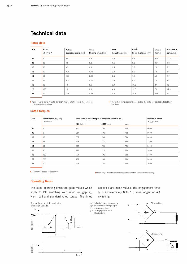
Rated data
The listed operating times are guide values which apply to DC switching with rated air gap sLr, warm coil and standard rated torque. The times
specified are mean values. The engagement time t1 is approximately 8 to 10 times longer for AC switching.
AC switching
DC switching
t11 = Delay time when connectingt12 = Rise time of braking torquet1 = Engagement timet2 = Disengagement timet3 = Slipping time
Torque time rated dependent on excitation voltage
Rate
d to
rque
Exci
tatio
n
Time
Time
Size PN [W] SLNmax SLmax max. min.2) Jalurotor Mass stator
[at 20°C] 1) Operating brake [mm] Holding brake [mm] Adjustment [mm] Rotor thickness [mm] [kgcm2] compl. [kg]
06 20 0.5 0.3 1.5 4.5 0.15 0.75
08 25 0.5 0.3 1.5 5.5 0.61 1.2
10 30 0.5 0.3 1.5 7.5 2.0 2.1
12 40 0.75 0.45 2.0 8.0 4.5 3.5
14 50 0.75 0.45 2.5 7.5 6.3 5.2
16 55 0.75 0.45 3.5 8.0 15 7.9
18 85 1.0 0.6 3.0 10.0 29 12
20 100 1.0 0.6 4.0 12.0 73 19.3
25 110 1.25 0.75 4.5 15.5 200 29.1
❙ 1) Coil power at 20˚C in watts, deviation of up to ±10% possible dependent on the selected coil voltage.
❙ 2) The friction lining is dimensioned so that the brake can be readjusted at least five times
Size Rated torque MK [Nm] Reduction of rated torque at specified speed to x% Maximum speed [100 r/min] nmax [r/min] 1500 r/min 3000 r/min max.
06 4 87% 80% 74% 6000
08 8 85% 78% 73% 5000
10 16 83% 76% 73% 4000
12 32 81% 74% 73% 3600
14 60 80% 73% 72% 3600
16 80 79% 72% 70% 3600
18 150 77% 70% 68% 3600
20 260 75% 68% 66% 3600
25 400 73% 66% 66% 3000
Rated torques
❙As speed increases, so does wear
Operating times
❙Maximum permissible rotational speed referred on standard friction lining
M
Mdyn
0.1M
dyn
Technical data
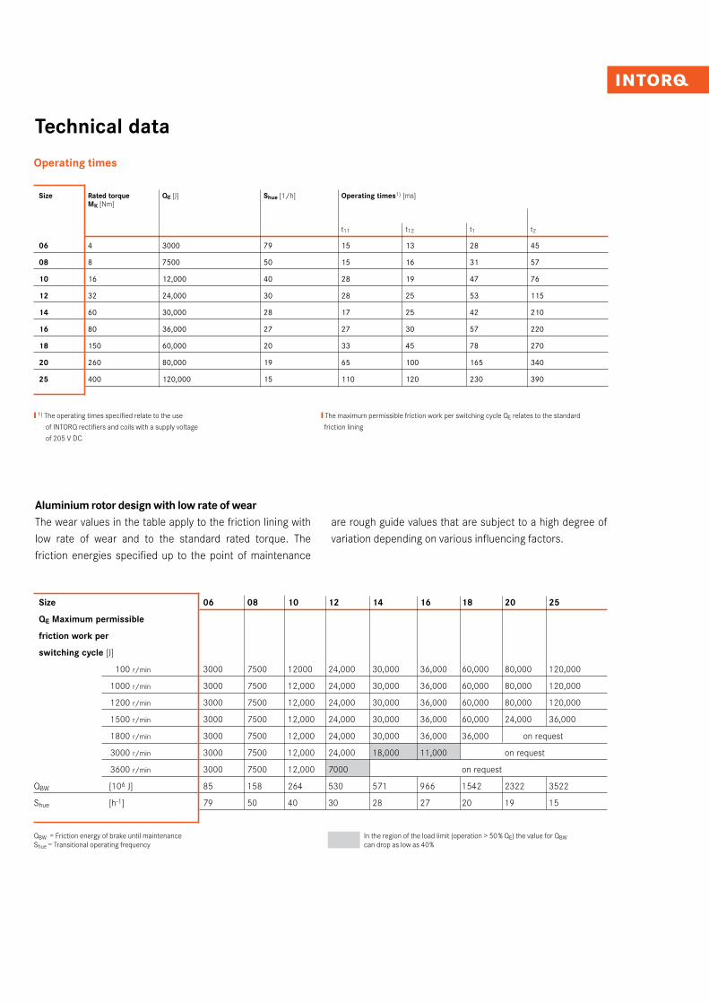
Operating times
Size Rated torque QE [J] Shue [1/h] Operating times1) [ms] MK [Nm]
t11 t12 t1 t2
06 4 3000 79 15 13 28 45
08 8 7500 50 15 16 31 57
10 16 12,000 40 28 19 47 76
12 32 24,000 30 28 25 53 115
14 60 30,000 28 17 25 42 210
16 80 36,000 27 27 30 57 220
18 150 60,000 20 33 45 78 270
20 260 80,000 19 65 100 165 340
25 400 120,000 15 110 120 230 390
❙ 1) The operating times specified relate to the use
of INTORQ rectifiers and coils with a supply voltage
of 205 V DC
❙ The maximum permissible friction work per switching cycle QE relates to the standard
friction lining
Aluminium rotor design with low rate of wearThe wear values in the table apply to the friction lining with low rate of wear and to the standard rated torque. The friction energies specified up to the point of maintenance
are rough guide values that are subject to a high degree of variation depending on various influencing factors.
Size 06 08 10 12 14 16 18 20 25
QE Maximum permissible
friction work per
switching cycle [J]
3000 7500 12000 24,000 30,000 36,000 60,000 80,000 120,000
3000 7500 12,000 24,000 30,000 36,000 60,000 80,000 120,000
3000 7500 12,000 24,000 30,000 36,000 60,000 80,000 120,000
3000 7500 12,000 24,000 30,000 36,000 60,000 24,000 36,000
3000 7500 12,000 24,000 30,000 36,000 36,000 on request
3000 7500 12,000 24,000 18,000 11,000 on request
3000 7500 12,000 7000 on request
QBW [106 J] 85 158 264 530 571 966 1542 2322 3522
Shue [h-1] 79 50 40 30 28 27 20 19 15
100 r/min
1000 r/min
1200 r/min
1500 r/min
1800 r/min
3000 r/min
3600 r/min
QBW = Friction energy of brake until maintenanceShue = Transitional operating frequency
In the region of the load limit (operation > 50 % QE) the value for QBW can drop as low as 40%
INTORQ I BFK458 spring-applied brake18I19
Technical data
Service life and wear
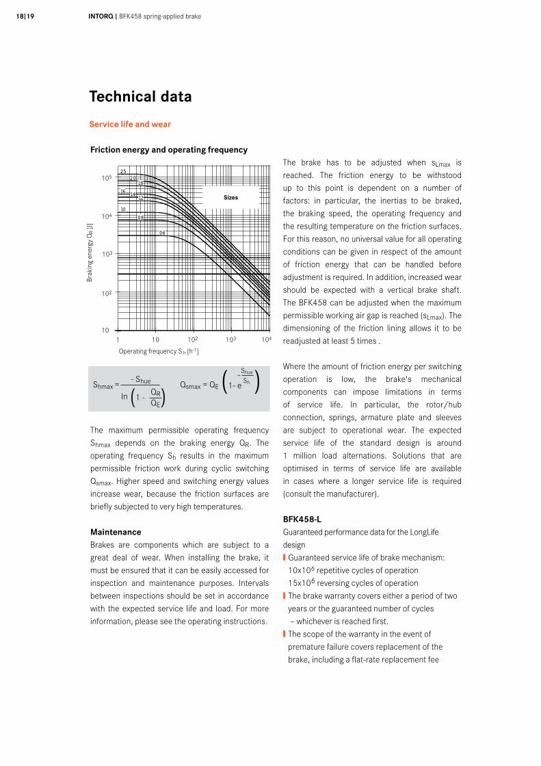
Friction energy and operating frequency
The maximum permissible operating frequency Shmax depends on the braking energy QR. The operating frequency Sh results in the maximum permissible friction work during cyclic switching Qsmax. Higher speed and switching energy values increase wear, because the friction surfaces are briefly subjected to very high temperatures.
MaintenanceBrakes are components which are subject to a great deal of wear. When installing the brake, it must be ensured that it can be easily accessed for inspection and maintenance purposes. Intervals between inspections should be set in accordance with the expected service life and load. For more information, please see the operating instructions.
The brake has to be adjusted when sLmax is reached. The friction energy to be withstood up to this point is dependent on a number of factors: in particular, the inertias to be braked, the braking speed, the operating frequency and the resulting temperature on the friction surfaces. For this reason, no universal value for all operating conditions can be given in respect of the amount of friction energy that can be handled before adjustment is required. In addition, increased wear should be expected with a vertical brake shaft. The BFK458 can be adjusted when the maximum permissible working air gap is reached (sLmax). The dimensioning of the friction lining allows it to be readjusted at least 5 times .
Where the amount of friction energy per switching operation is low, the brake's mechanical components can impose limitations in terms of service life. In particular, the rotor/hub connection, springs, armature plate and sleeves are subject to operational wear. The expected service life of the standard design is around 1 million load alternations. Solutions that are optimised in terms of service life are available in cases where a longer service life is required (consult the manufacturer).
BFK458-LGuaranteed performance data for the LongLife design❙ Guaranteed service life of brake mechanism: 10x106 repetitive cycles of operation 15x106 reversing cycles of operation❙ The brake warranty covers either a period of two years or the guaranteed number of cycles – whichever is reached first.❙ The scope of the warranty in the event of premature failure covers replacement of the brake, including a flat-rate replacement fee
10
100
1.000
10.000
100.000
1.000.000
1 10 100 1.000 10.000
SchalthŠufigkeit Sh [h-1]
Scha
ltarb
eit Q
[J]
2520
1816 14
12
1008
06
Operating frequency S h [h-1]
105
104
103
102
Brak
ing
ener
gy Q
R [J]
Sizes
1 10 102 103 10410
Shmax = - Shue Qsmax = QE
(1- e-Shue )
In (1 - QR)
Sh
QE
Accessories
Hand release
The hand release is used to release the brake by hand and can be retrofitted. The hand release springs back to its base position automatically after operation (1). The hand release requires an additional air gap SHL in order to function; this is factory-set prior to delivery. Dimension SHL (see the mounting instructions) must be checked once the equipment has been mounted.
Size sLN +0.1 sHL +0.1
-0.05
[mm] [mm]
06 08 0.2 1 10
12 14 0.3 1.5 16
18 0.4 2 20
25 0.5 2.5
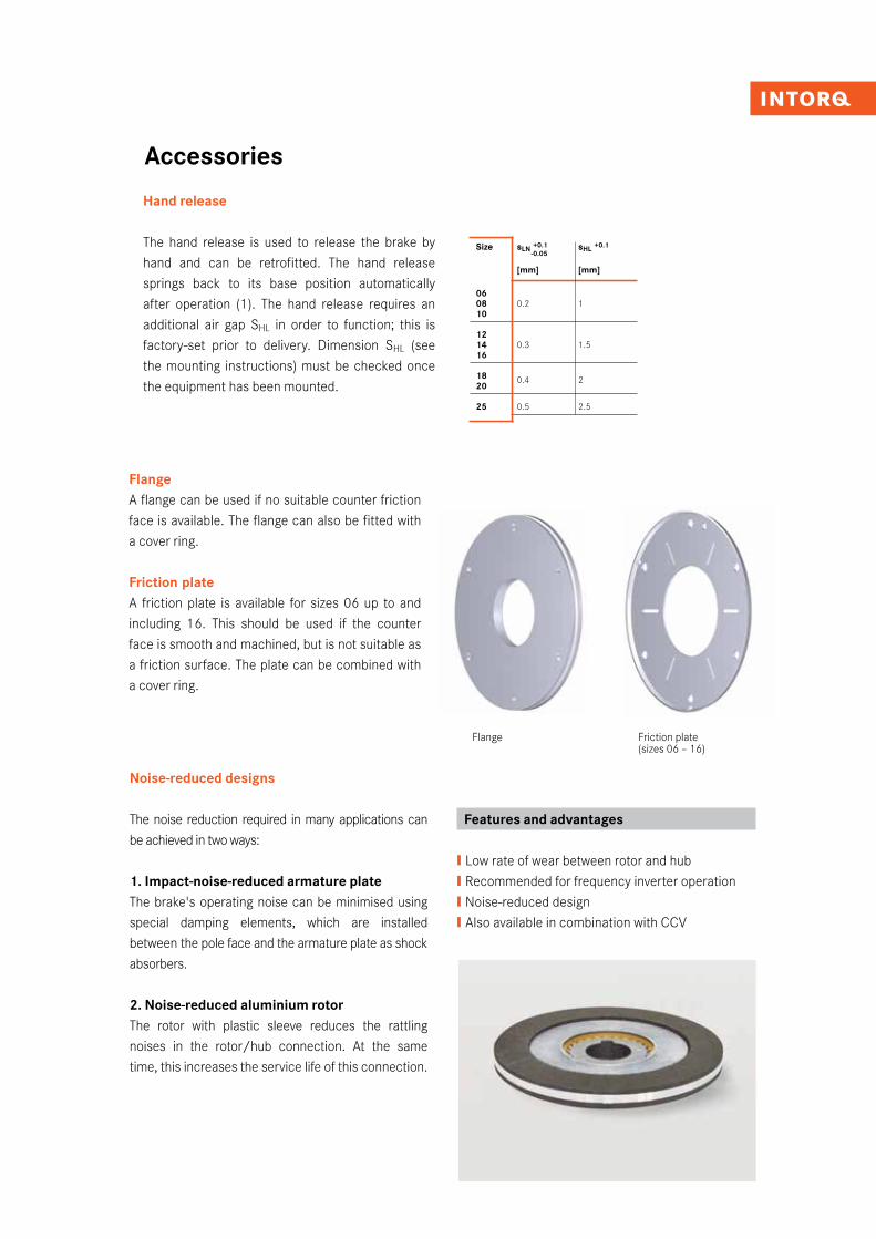
FlangeA flange can be used if no suitable counter friction face is available. The flange can also be fitted with a cover ring.
Friction plateA friction plate is available for sizes 06 up to and including 16. This should be used if the counter face is smooth and machined, but is not suitable as a friction surface. The plate can be combined with a cover ring.
Flange Friction plate (sizes 06 – 16)
Noise-reduced designs
The noise reduction required in many applications can be achieved in two ways:
1. Impact-noise-reduced armature plateThe brake's operating noise can be minimised using special damping elements, which are installed between the pole face and the armature plate as shock absorbers.
2. Noise-reduced aluminium rotorThe rotor with plastic sleeve reduces the rattling noises in the rotor/hub connection. At the same time, this increases the service life of this connection.
Features and advantages
❙ Low rate of wear between rotor and hub ❙ Recommended for frequency inverter operation❙ Noise-reduced design❙ Also available in combination with CCV
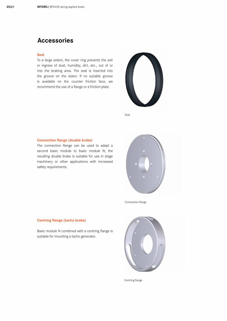
Seal
Connection flange
Centring flange
INTORQ I BFK458 spring-applied brake20I21
Accessories
SealTo a large extent, the cover ring prevents the exit or ingress of dust, humidity, dirt, etc., out of or into the braking area. The seal is inserted into the groove on the stator. If no suitable groove is available on the counter friction face, we recommend the use of a flange or a friction plate.
Connection flange (double brake)The connection flange can be used to adapt a second basic module to basic module N; the resulting double brake is suitable for use in stage machinery or other applications with increased safety requirements.
Centring flange (tacho brake)
Basic module N combined with a centring flange is suitable for mounting a tacho generator.
Accessories
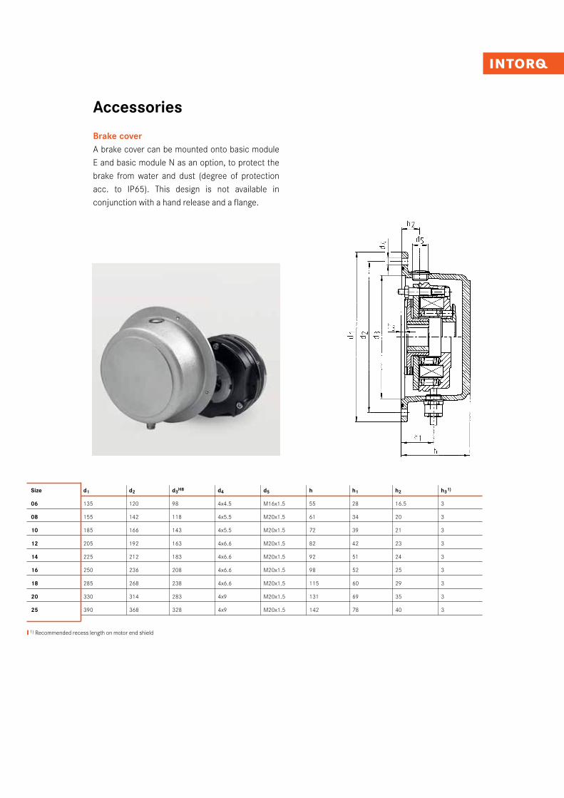
Brake cover
Size d1 d2 d3H8 d4 d5 h h1 h2 h31)
06 135 120 98 4x4.5 M16x1.5 55 28 16.5 3
08 155 142 118 4x5.5 M20x1.5 61 34 20 3
10 185 166 143 4x5.5 M20x1.5 72 39 21 3
12 205 192 163 4x6.6 M20x1.5 82 42 23 3
14 225 212 183 4x6.6 M20x1.5 92 51 24 3
16 250 236 208 4x6.6 M20x1.5 98 52 25 3
18 285 268 238 4x6.6 M20x1.5 115 60 29 3
20 330 314 283 4x9 M20x1.5 131 69 35 3
25 390 368 328 4x9 M20x1.5 142 78 40 3
A brake cover can be mounted onto basic module E and basic module N as an option, to protect the brake from water and dust (degree of protection acc. to IP65). This design is not available in conjunction with a hand release and a flange.
❙ 1) Recommended recess length on motor end shield
INTORQ I BFK458 spring-applied brake22I23
Accessories
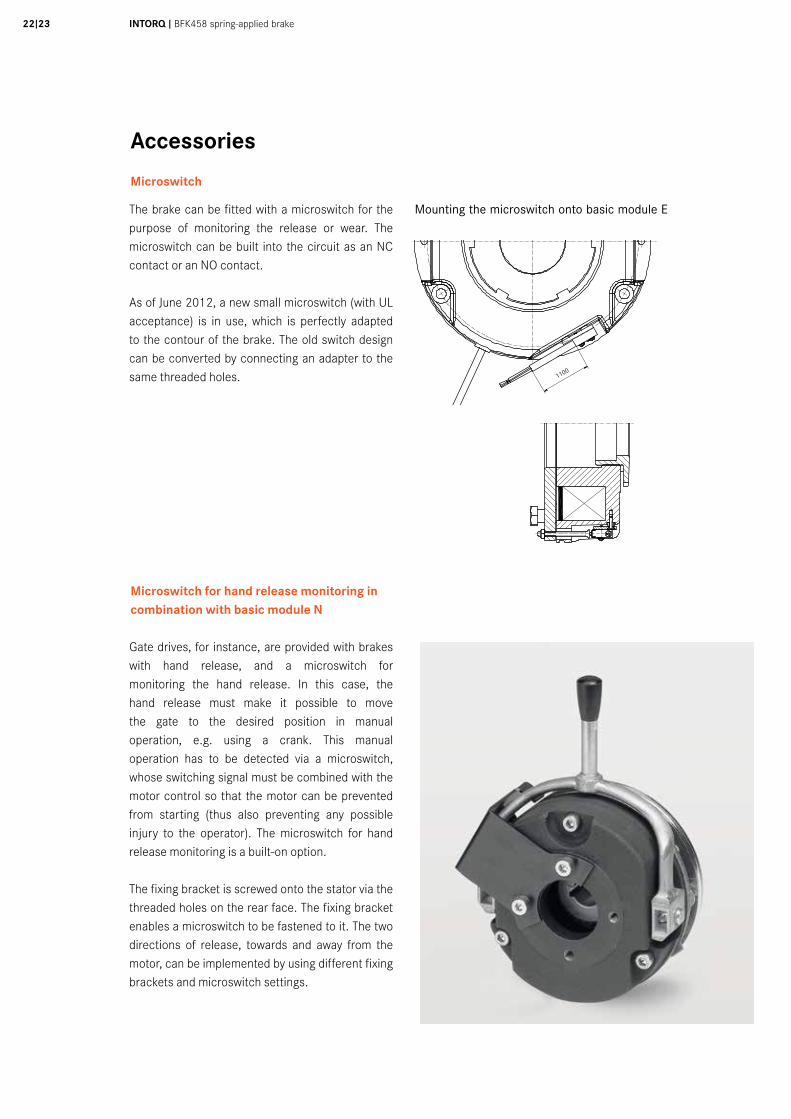
Microswitch
The brake can be fitted with a microswitch for the purpose of monitoring the release or wear. The microswitch can be built into the circuit as an NC contact or an NO contact.
As of June 2012, a new small microswitch (with UL acceptance) is in use, which is perfectly adapted to the contour of the brake. The old switch design can be converted by connecting an adapter to the same threaded holes.
Tol.Maß/tol. size
Abmaß/deviation
Tol.Maß/tol. size
Abmaß/deviation
Ind./ Anz./ind. quan.
Änder-Nr./revision no.
Datum/date
Name/name
Datum/date Name/name
Bea/drn
Gepr/chkd
Norm/appr
Datei/file
Benennung/name of drawing
Zeichnungsnummer/drawing no.
Ersatz fuer/back-up for
Werkstoff/material
Maßstab/scale Gewicht/weight
Blatt/sheet
Allgemeintoleranzen/general tolerance
Oberflächen/surface
DIN ISO 1302
X
Y
Z
Rz25
Rz6,3
Rz1
CAD
BMK45816-001E_MS.iami
5020
1030
40m
m0
Schu
tzve
rmer
k IS
O 1
6016
bea
chte
n. C
opyr
ight
rese
rved
.
1 2 3 4 5 6 7 8 9 10 11 12
A
B
C
D
E
F
G
H
1 2 3 4 5 6 7 8 9 10 11 12
A
B
C
D
E
F
G
H
Tol.Maß/tol. size
Abmaß/deviation
Tol.Maß/tol. size
Abmaß/deviation
Ind./ Anz./ind. quan.
Änder-Nr./revision no.
Datum/date
Name/name
Datum/date Name/name
Bea/drn
Gepr/chkd
Norm/appr
Datei/file
Benennung/name of drawing
Zeichnungsnummer/drawing no.
Ersatz fuer/back-up for
Werkstoff/material
Maßstab/scale Gewicht/weight
Blatt/sheet
Allgemeintoleranzen/general tolerance
Oberflächen/surface
DIN ISO 1302
X
Y
Z
Rz25
Rz6,3
Rz1
CAD
BMK45816-001E_MS.iami
5020
1030
40m
m0
Schu
tzve
rmer
k IS
O 1
6016
bea
chte
n. C
opyr
ight
rese
rved
.
1 2 3 4 5 6 7 8 9 10 11 12
A
B
C
D
E
F
G
H
1 2 3 4 5 6 7 8 9 10 11 12
A
B
C
D
E
F
G
H
Mounting the microswitch onto basic module E
Gate drives, for instance, are provided with brakes with hand release, and a microswitch for monitoring the hand release. In this case, the hand release must make it possible to move the gate to the desired position in manual operation, e.g. using a crank. This manual operation has to be detected via a microswitch, whose switching signal must be combined with the motor control so that the motor can be prevented from starting (thus also preventing any possible injury to the operator). The microswitch for hand release monitoring is a built-on option.
The fixing bracket is screwed onto the stator via the threaded holes on the rear face. The fixing bracket enables a microswitch to be fastened to it. The two directions of release, towards and away from the motor, can be implemented by using different fixing brackets and microswitch settings.
Microswitch for hand release monitoring incombination with basic module N
1100
Accessories
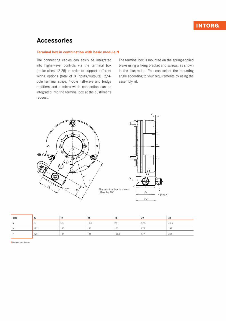
Terminal box in combination with basic module N
Size 12 14 16 18 20 25
b -5 5.5 12.5 23 37.5 45.5
h 122 130 142 155 174 198
r 126 134 146 158.5 177 201
The connecting cables can easily be integrated into higher-level controls via the terminal box (brake sizes 12-25) in order to support different wiring options (total of 3 inputs/outputs). 2/4-pole terminal strips, 4-pole half-wave and bridge rectifiers and a microswitch connection can be integrated into the terminal box at the customer's request.
The terminal box is mounted on the spring-applied brake using a fixing bracket and screws, as shown in the illustration. You can select the mounting angle according to your requirements by using the assembly kit.
The terminal box is shown offset by 30°
❙Dimensions in mm
INTORQ I BFK458 spring-applied brake24I25
Accessories
Bridge rectifiers and half-wave rectifiersType code B E G – 5 6 1 – 440
BrakeElectronicsRectifier
1-Bridge rectifier2-Half-wave rectifier5-Bridge/half-wave rectifier
4-pole6-pole
1-Mounting position horizontal2-Mounting position vertical3-Mounting position horizontal with snap-in stud
440 Voltage 440 V AC
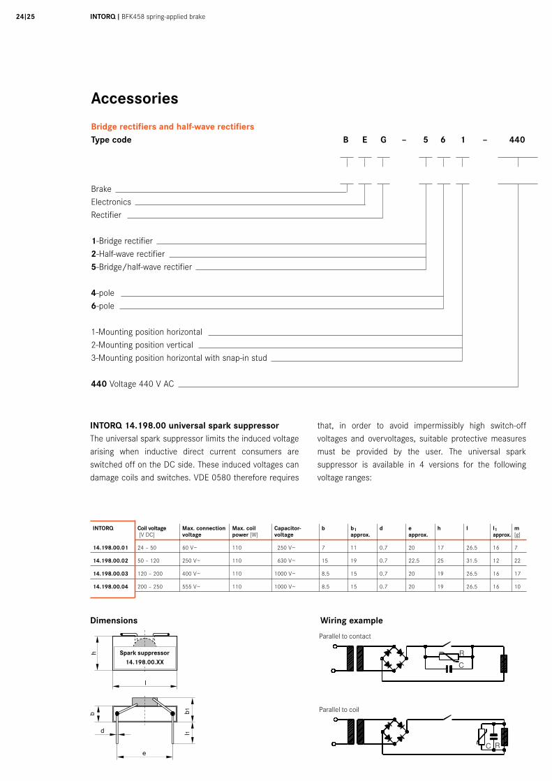
INTORQ 14.198.00 universal spark suppressorThe universal spark suppressor limits the induced voltage arising when inductive direct current consumers are switched off on the DC side. These induced voltages can damage coils and switches. VDE 0580 therefore requires
that, in order to avoid impermissibly high switch-off voltages and overvoltages, suitable protective measures must be provided by the user. The universal spark suppressor is available in 4 versions for the following voltage ranges:
INTORQ Coil voltage Max. connection Max. coil Capacitor- b b1 d e h l l1 m [V DC] voltage power [W] voltage approx. approx. approx. [g]
14.198.00.01 24 – 50 60 V~ 110 250 V~ 7 11 0.7 20 17 26.5 16 7
14.198.00.02 50 – 120 250 V~ 110 630 V~ 15 19 0.7 22.5 25 31.5 12 22
14.198.00.03 120 – 200 400 V~ 110 1000 V~ 8.5 15 0.7 20 19 26.5 16 17
14.198.00.04 200 – 250 555 V~ 110 1000 V~ 8.5 15 0.7 20 19 26.5 16 10
Dimensions Wiring example
Parallel to contact
Parallel to coil
Spark suppressor14.198.00.XX
Accessories
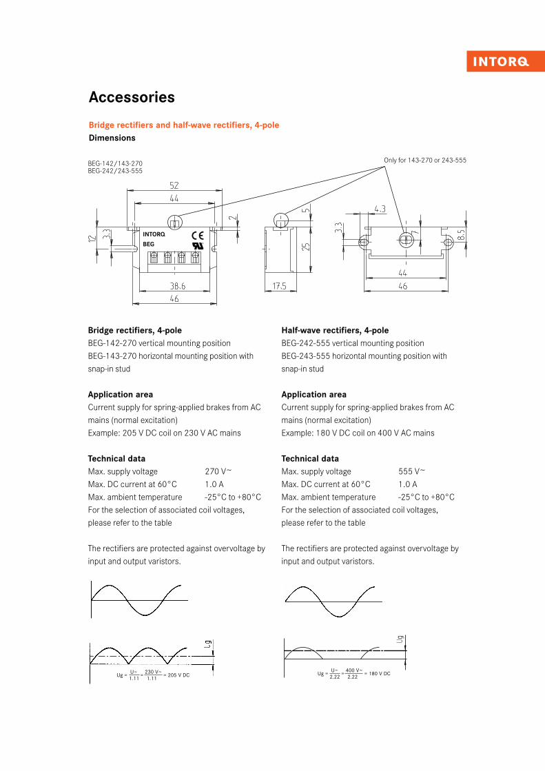
Bridge rectifiers and half-wave rectifiers, 4-poleDimensions
Bridge rectifiers, 4-poleBEG-142-270 vertical mounting position BEG-143-270 horizontal mounting position with snap-in stud
Application areaCurrent supply for spring-applied brakes from AC mains (normal excitation)Example: 205 V DC coil on 230 V AC mains
Technical dataMax. supply voltage 270 V~Max. DC current at 60°C 1.0 AMax. ambient temperature -25°C to +80°CFor the selection of associated coil voltages, please refer to the table
The rectifiers are protected against overvoltage by input and output varistors.
BEG-142/143-270
Ug = U~
= 230 V~
= 205 V DC 1.11 1.11
Ug = U~
= 400 V~
= 180 V DC 2.22 2.22
Half-wave rectifiers, 4-poleBEG-242-555 vertical mounting positionBEG-243-555 horizontal mounting position with snap-in stud
Application areaCurrent supply for spring-applied brakes from AC mains (normal excitation)Example: 180 V DC coil on 400 V AC mains
Technical dataMax. supply voltage 555 V~Max. DC current at 60°C 1.0 AMax. ambient temperature -25°C to +80°CFor the selection of associated coil voltages, please refer to the table
The rectifiers are protected against overvoltage by input and output varistors.
BEG-142/143-270BEG-242/243-555
Only for 143-270 or 243-555
INTORQ
BEG
INTORQ I BFK458 spring-applied brake26I27
Accessories
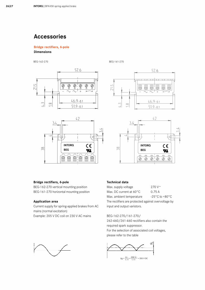
Bridge rectifiers, 6-poleDimensions
BEG-162-270 BEG-161-270
Bridge rectifiers, 6-poleBEG-162-270 vertical mounting positionBEG-161-270 horizontal mounting position
Application areaCurrent supply for spring-applied brakes from AC mains (normal excitation)Example: 205 V DC coil on 230 V AC mains
Technical dataMax. supply voltage 270 V~Max. DC current at 60°C 0.75 AMax. ambient temperature -25°C to +80°CThe rectifiers are protected against overvoltage by input and output varistors.
BEG-162-270/161-270/ 262-460/261-460 rectifiers also contain the required spark suppressor.For the selection of associated coil voltages, please refer to the table
Ug = U~
= 230 V~
= 205 V DC 1.11 1.11
BEG-162-270 BEG-161-270BEG-162-270 BEG-161-270INTORQ
BEGINTORQ
BEG
Accessories
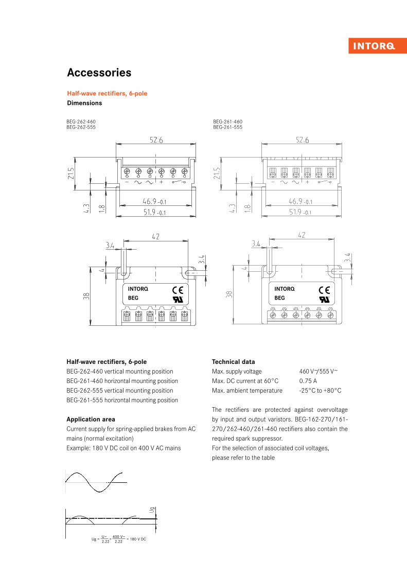
Half-wave rectifiers, 6-poleDimensions
Half-wave rectifiers, 6-poleBEG-262-460 vertical mounting positionBEG-261-460 horizontal mounting positionBEG-262-555 vertical mounting positionBEG-261-555 horizontal mounting position
Application areaCurrent supply for spring-applied brakes from AC mains (normal excitation)Example: 180 V DC coil on 400 V AC mains
Technical dataMax. supply voltage 460 V~/555 V~Max. DC current at 60°C 0.75 AMax. ambient temperature -25°C to +80°C
The rectifiers are protected against overvoltage by input and output varistors. BEG-162-270/161-270/262-460/261-460 rectifiers also contain the required spark suppressor.For the selection of associated coil voltages, please refer to the table
Ug = U~
= 400 V~
= 180 V DC 2.22 2.22
BEG-262-460 BEG-261-460BEG-262-460 BEG-261-460
BEG-262-460 BEG-261-460BEG-262-555 BEG-261-555
INTORQ
BEG
INTORQ
BEG
INTORQ I BFK458 spring-applied brake28I29
Accessories
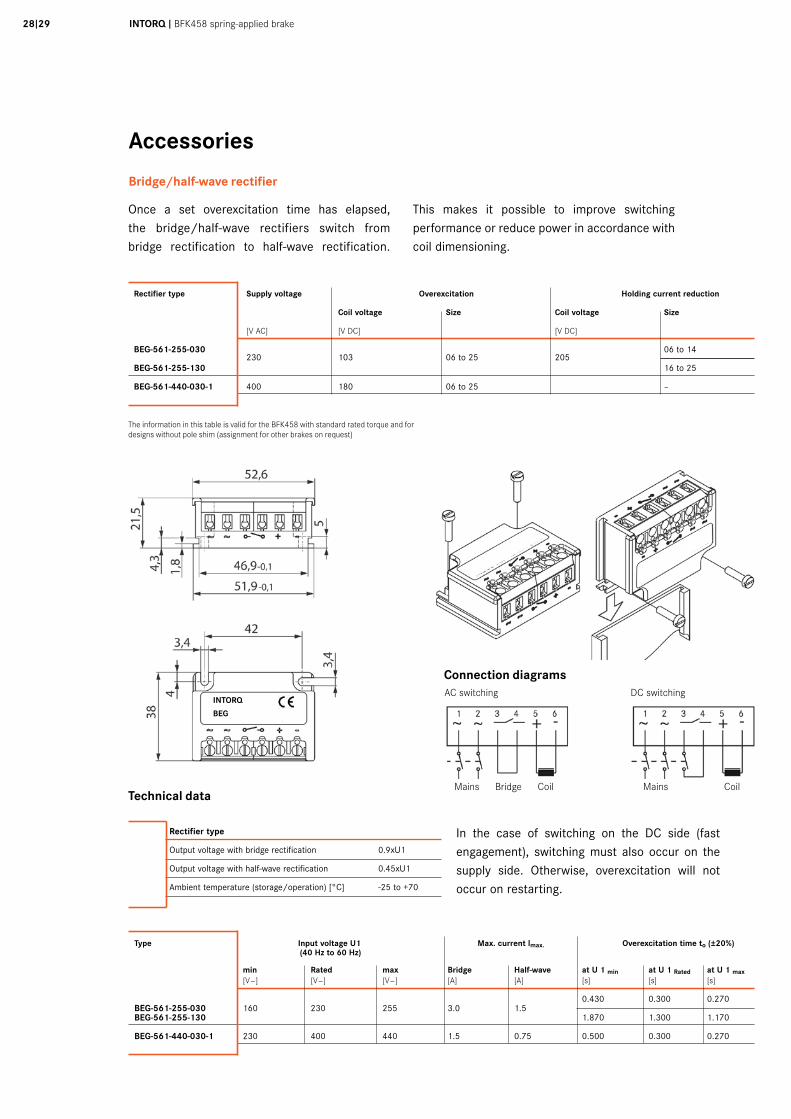
Bridge/half-wave rectifier
Once a set overexcitation time has elapsed, the bridge/half-wave rectifiers switch from bridge rectification to half-wave rectification.
This makes it possible to improve switching performance or reduce power in accordance with coil dimensioning.
The information in this table is valid for the BFK458 with standard rated torque and for designs without pole shim (assignment for other brakes on request)
Dimensions
Rectifier type Supply voltage Overexcitation Holding current reduction Coil voltage Size Coil voltage Size
[V AC] [V DC] [V DC]
BEG-561-255-030 230 103
06 to 25
205
06 to 14
BEG-561-255-130 16 to 25
BEG-561-440-030-1 400 180 06 to 25 –
Rectifier type
Output voltage with bridge rectification 0.9xU1
Output voltage with half-wave rectification 0.45xU1
Ambient temperature (storage/operation) [°C] -25 to +70
Technical data
Connection diagrams
Mains Bridge Coil Mains Coil
In the case of switching on the DC side (fast engagement), switching must also occur on the supply side. Otherwise, overexcitation will not occur on restarting.
Type Input voltage U1 Max. current lmax. Overexcitation time to (±20%) (40 Hz to 60 Hz)
min Rated max Bridge Half-wave at U 1 min at U 1 Rated at U 1 max [V~] [V~] [V~] [A] [A] [s] [s] [s]
BEG-561-255-030 160 230 255 3.0 1.5 0.430 0.300 0.270
BEG-561-255-130 1.870 1.300 1.170
BEG-561-440-030-1 230 400 440 1.5 0.75 0.500 0.300 0.270
INTORQ
BEG
AC switching DC switching
Accessories
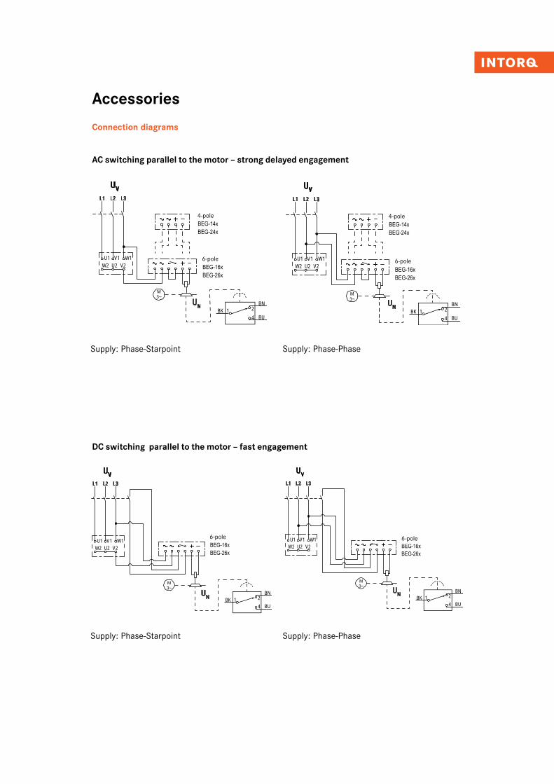
Connection diagrams
AC switching parallel to the motor – strong delayed engagement
DC switching parallel to the motor – fast engagement
Elektrische Installation
INTORQ | BA 14.0168 | 09/2015 43
6.2 Wechselstromseitiges Schalten am Motor - stark verzögertes Verknüpfen
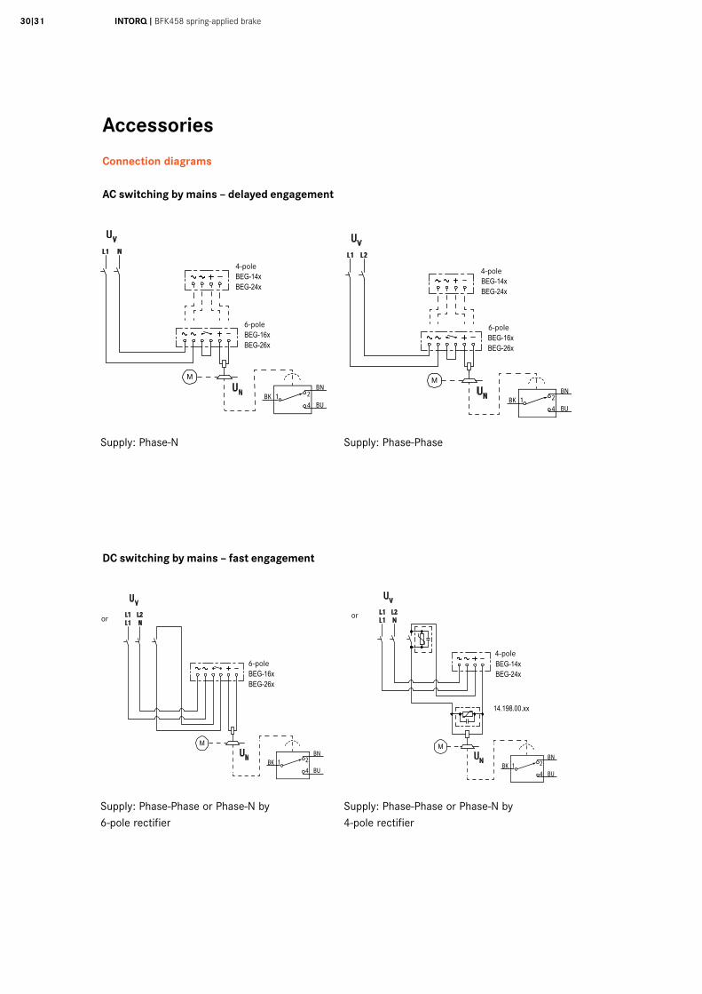
Abb. 21 Versorgung: Phase-Sternpunkt
Brückengleichrichter EinweggleichrichterBEG-1xx: UN [VDC]=0.9 • [VAC] BEG-2xx: UN [VDC]=0.45 • [VAC]
Abb. 22 Versorgung: Phase-Phase
Brückengleichrichter1) EinweggleichrichterBEG-1xx: UN [VDC]=0.9 • UV [VAC] BEG-2xx: UN [VDC]=0.45 • UV [VAC]1) nicht sinnvoll bei den meisten länderspezifischen hohen Netzspannungen
U2W2 V2
UN
L1 L2 L3
UV
V1U1 W1
UV
BNBK
BU421
4-poligBEG-14xBEG-24x
6-poligBEG-16xBEG-26x
Uv3
---------Uv
3---------
U2W2 V2
UN
L1 L2 L3
UV
V1U1 W1
UV
BNBK
BU421
4-poligBEG-14xBEG-24x
6-poligBEG-16xBEG-26x
Elektrische Installation
INTORQ | BA 14.0168 | 09/2015 43
6.2 Wechselstromseitiges Schalten am Motor - stark verzögertes Verknüpfen
Abb. 21 Versorgung: Phase-Sternpunkt
Brückengleichrichter EinweggleichrichterBEG-1xx: UN [VDC]=0.9 • [VAC] BEG-2xx: UN [VDC]=0.45 • [VAC]
Abb. 22 Versorgung: Phase-Phase
Brückengleichrichter1) EinweggleichrichterBEG-1xx: UN [VDC]=0.9 • UV [VAC] BEG-2xx: UN [VDC]=0.45 • UV [VAC]1) nicht sinnvoll bei den meisten länderspezifischen hohen Netzspannungen
U2W2 V2
UN
L1 L2 L3
UV
V1U1 W1
UV
BNBK
BU421
4-poligBEG-14xBEG-24x
6-poligBEG-16xBEG-26x
Uv3
---------Uv
3---------
U2W2 V2
UN
L1 L2 L3
UV
V1U1 W1
UV
BNBK
BU421
4-poligBEG-14xBEG-24x
6-poligBEG-16xBEG-26x
Supply: Phase-Starpoint Supply: Phase-Phase
Elektrische Installation
INTORQ | BA 14.0168 | 09/2015 44
6.3 Gleichstromseitiges Schalten am Motor - schnelles Verknüpfen
Abb. 23 Versorgung: Phase-Sternpunkt
Brückengleichrichter EinweggleichrichterBEG-1xx: UN [VDC]=0.9 • [VAC] BEG-2xx: UN [VDC]=0.45 • [VAC]
Abb. 24 Versorgung: Phase-Phase
Brückengleichrichter1) EinweggleichrichterBEG-1xx: UN [VDC]=0.9 • UV [VAC] BEG-2xx: UN [VDC]=0.45 • UV [VAC]1) nicht sinnvoll bei den meisten länderspezifischen hohen Netzspannungen
UN
L1 L2 L3
UVUV
U2W2 V2V1U1 W1
BNBK
BU421
6-poligBEG-16xBEG-26x
Uv3
---------Uv
3---------
U2W2 V2
UN
L1 L2 L3
UV
V1U1 W1
UV
BNBK
BU421
6-poligBEG-16xBEG-26x
Supply: Phase-Starpoint Supply: Phase-Phase
4-pole 4-pole
6-pole 6-pole
6-pole 6-pole
INTORQ I BFK458 spring-applied brake30I31
Accessories
Connection diagrams
AC switching by mains – delayed engagement
DC switching by mains – fast engagement
Elektrische Installation
INTORQ | BA 14.0168 | 09/2015 45
6.4 Wechselstromseitiges Schalten am Netz - verzögertes Verknüpfen
Abb. 25 Versorgung: Phase-N
Brückengleichrichter EinweggleichrichterBEG-1xx: UN [VDC]=0.9 • UV [VAC] BEG-2xx: UN [VDC]=0.45 • UV [VAC]
Abb. 26 Versorgung: Phase-Phase
Brückengleichrichter1) EinweggleichrichterBEG-1xx: UN [VDC]=0.9 • UV [VAC] BEG-2xx: UN [VDC]=0.45 • UV [VAC]1) nicht sinnvoll bei den meisten länderspezifischen hohen Netzspannungen
UN
L1 N
UV
BNBK
BU421
4-poligBEG-14xBEG-24x
6-poligBEG-16xBEG-26x
L1 L2
UV
UNBN
BKBU4
21
4-poligBEG-14xBEG-24x
6-poligBEG-16xBEG-26x
Supply: Phase-N Supply: Phase-Phase
Elektrische Installation
INTORQ | BA 14.0168 | 09/2015 46
6.5 Gleichstromseitiges Schalten am Netz - schnelles Verknüpfen
Abb. 27 Versorgung: Phase-Phase oder Phase-N über 6-poligen Gleichrichter
Brückengleichrichter1) EinweggleichrichterBEG-16x: UN [VDC]=0.9 • UV [VAC] BEG-26x: UN [VDC]=0.45 • UV [VAC]1) bei den meisten länderspezifischen hohen Netzspannungen nur sinnvoll bei Versorgungen über L1 und N
Abb. 28 Versorgung: Phase-Phase oder Phase-N über 4-poligen Gleichrichter
Brückengleichrichter1) EinweggleichrichterBEG-14x: UN [VDC]=0.9 • UV [VAC] BEG-24x: UN [VDC]=0.45 • UV [VAC]Funkenlöschglied:14.198.00.xx (einmal benötigt, Position wahlweise)1) bei den meisten länderspezifischen hohen Netzspannungen nur sinnvoll bei Versorgungen über L1 und N
UN
L1 NL1 L2
UV
BNBK
BU421
6-poligBEG-16xBEG-26x
oder
L1 NL1 L2
UV
UN BNBK
BU421
4-poligBEG-14xBEG-24x
14.198.00.xx
oder
Supply: Phase-Phase or Phase-N by 6-pole rectifier
Supply: Phase-Phase or Phase-N by 4-pole rectifier
4-pole4-pole
6-pole6-pole
6-pole4-pole
or or
Accessories
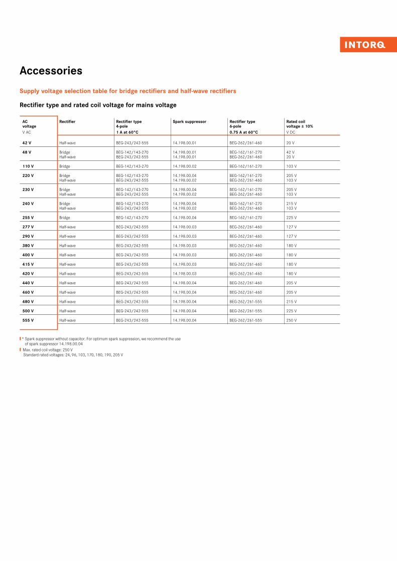
Supply voltage selection table for bridge rectifiers and half-wave rectifiers
Rectifier type and rated coil voltage for mains voltage
AC Rectifier Rectifier type Spark suppressor Rectifier type Rated coil voltage 4-pole 6-pole voltage ± 10%
V AC 1 A at 60°C 0.75 A at 60°C V DC
42 V Half-wave BEG-243/242-555 14.198.00.01 BEG-262/261-460 20 V
48 V Bridge BEG-142/143-270 14.198.00.01 BEG-162/161-270 42 V Half-wave BEG-243/242-555 14.198.00.01 BEG-262/261-460 20 V
110 V Bridge BEG-142/143-270 14.198.00.02 BEG-162/161-270 103 V
220 V Bridge BEG-142/143-270 14.198.00.04 BEG-162/161-270 205 V Half-wave BEG-243/242-555 14.198.00.02 BEG-262/261-460 103 V
230 V Bridge BEG-142/143-270 14.198.00.04 BEG-162/161-270 205 V Half-wave BEG-243/242-555 14.198.00.02 BEG-262/261-460 103 V
240 V Bridge BEG-142/143-270 14.198.00.04 BEG-162/161-270 215 V Half-wave BEG-243/242-555 14.198.00.02 BEG-262/261-460 103 V
255 V Bridge BEG-142/143-270 14.198.00.04 BEG-162/161-270 225 V
277 V Half-wave BEG-243/242-555 14.198.00.03 BEG-262/261-460 127 V
290 V Half-wave BEG-243/242-555 14.198.00.03 BEG-262/261-460 127 V
380 V Half-wave BEG-243/242-555 14.198.00.03 BEG-262/261-460 180 V
400 V Half-wave BEG-243/242-555 14.198.00.03 BEG-262/261-460 180 V
415 V Half-wave BEG-243/242-555 14.198.00.03 BEG-262/261-460 180 V
420 V Half-wave BEG-243/242-555 14.198.00.03 BEG-262/261-460 180 V
440 V Half-wave BEG-243/242-555 14.198.00.04 BEG-262/261-460 205 V
460 V Half-wave BEG-243/242-555 14.198.00.04 BEG-262/261-460 205 V
480 V Half-wave BEG-243/242-555 14.198.00.04 BEG-262/261-555 215 V
500 V Half-wave BEG-243/242-555 14.198.00.04 BEG-262/261-555 225 V
555 V Half-wave BEG-243/242-555 14.198.00.04 BEG-262/261-555 250 V
❙ * Spark suppressor without capacitor. For optimum spark suppression, we recommend the use of spark suppressor 14.198.00.04
❙ Max. rated coil voltage: 250 V Standard rated voltages: 24, 96, 103, 170, 180, 190, 205 V
INTORQ I BFK458 spring-applied brake32I33
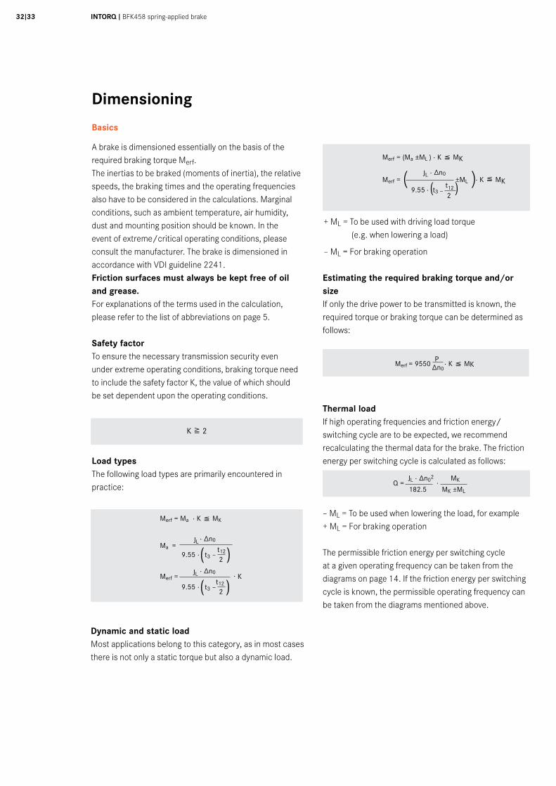
Dimensioning
Basics
+ ML = To be used with driving load torque (e.g. when lowering a load)
– ML = For braking operation
A brake is dimensioned essentially on the basis of the required braking torque Merf.The inertias to be braked (moments of inertia), the relative speeds, the braking times and the operating frequencies also have to be considered in the calculations. Marginal conditions, such as ambient temperature, air humidity, dust and mounting position should be known. In the event of extreme/critical operating conditions, please consult the manufacturer. The brake is dimensioned in accordance with VDI guideline 2241.Friction surfaces must always be kept free of oil and grease. For explanations of the terms used in the calculation, please refer to the list of abbreviations on page 5.
Safety factorTo ensure the necessary transmission security even under extreme operating conditions, braking torque need to include the safety factor K, the value of which should be set dependent upon the operating conditions.
Load typesThe following load types are primarily encountered in practice:
Merf = Ma · K ( MK
Merf = (Ma ±ML ) · K ( MK
Merf = JL
· ∆n0 ±ML · K ( MK
9.55 ·
t3 –
t12
( 2
)
Dynamic and static loadMost applications belong to this category, as in most cases there is not only a static torque but also a dynamic load.
Merf = 9550
P · K ( MK ∆n0
Estimating the required braking torque and/or sizeIf only the drive power to be transmitted is known, the required torque or braking torque can be determined as follows:
Thermal loadIf high operating frequencies and friction energy/switching cycle are to be expected, we recommend recalculating the thermal data for the brake. The friction energy per switching cycle is calculated as follows:
– ML = To be used when lowering the load, for example+ ML = For braking operation
The permissible friction energy per switching cycle at a given operating frequency can be taken from the diagrams on page 14. If the friction energy per switching cycle is known, the permissible operating frequency can be taken from the diagrams mentioned above.
K 8 2
Q = JL · ∆n02
· MK
Merf = · Kt3 –
t12
2
· ∆n0JL
( )9.55 ·
Ma = t3 –
t12
2
· ∆n0JL
( )9.55 ·
182.5 MK ±ML
( )
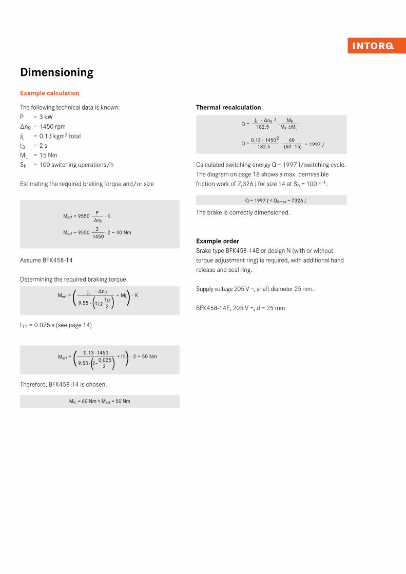
Dimensioning
Example calculation
Merf = +15 · 2 = 50 Nm
The following technical data is known:P = 3 kW∆n0 = 1450 rpmJL = 0.13 kgm2 totalt3 = 2 sML = 15 NmSh = 100 switching operations/h
Estimating the required braking torque and/or size
Merf = 9550 P
· K ∆n0
Merf = 9550 3
· 2 = 40 Nm 1450
Assume BFK458-14
Determining the required braking torque
t12 = 0.025 s (see page 14)
Therefore, BFK458-14 is chosen.
MK = 60 Nm > Merf = 50 Nm
( )
Thermal recalculation
Calculated switching energy Q = 1997 J/switching cycle.The diagram on page 18 shows a max. permissible friction work of 7,326 J for size 14 at Sh = 100 h-1.
Q = 1997 J < QSmax = 7326 J
The brake is correctly dimensioned.
Example orderBrake type BFK458-14E or design N (with or without torque adjustment ring) is required, with additional hand release and seal ring.
Supply voltage 205 V =, shaft diameter 25 mm.
BFK458-14E, 205 V =, d = 25 mm
Q = 0.13 · 14502
· 60
182.5 (60 -15)
0.13 ·1450
9.55 · 2–0.025
2
Q = JL · ∆n0 2
· MK
182.5 MK ±ML
= 1997 J
( )Merf = + ML
t12t12
2
· ∆n0JL
( )9.55 ·
· K
( )
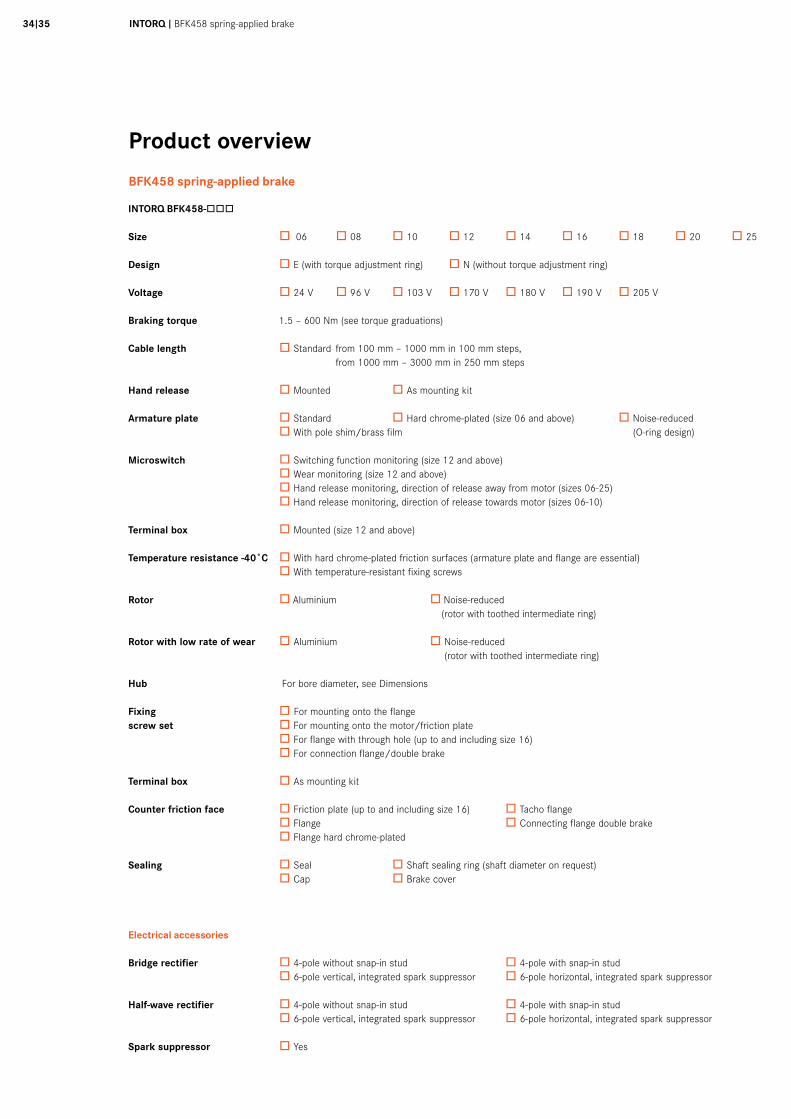
INTORQ I BFK458 spring-applied brake34I35
Product overview
BFK458 spring-applied brake
INTORQ BFK458-òòò
Size ò 06 ò 08 ò 10 ò 12 ò 14 ò 16 ò 18 ò 20 ò 25
Design ò E (with torque adjustment ring) ò N (without torque adjustment ring)
Voltage ò 24 V ò 96 V ò 103 V ò 170 V ò 180 V ò 190 V ò 205 V
Braking torque 1.5 – 600 Nm (see torque graduations)
Cable length ò Standard from 100 mm – 1000 mm in 100 mm steps, from 1000 mm – 3000 mm in 250 mm steps
Hand release ò Mounted ò As mounting kit
Armature plate ò Standard ò Hard chrome-plated (size 06 and above) ò Noise-reduced ò With pole shim/brass film (O-ring design) Microswitch ò Switching function monitoring (size 12 and above) ò Wear monitoring (size 12 and above) ò Hand release monitoring, direction of release away from motor (sizes 06-25) ò Hand release monitoring, direction of release towards motor (sizes 06-10)
Terminal box ò Mounted (size 12 and above)
Temperature resistance -40˚C ò With hard chrome-plated friction surfaces (armature plate and flange are essential) ò With temperature-resistant fixing screws
Rotor ò Aluminium ò Noise-reduced (rotor with toothed intermediate ring)
Rotor with low rate of wear ò Aluminium ò Noise-reduced (rotor with toothed intermediate ring)
Hub For bore diameter, see Dimensions
Fixing òFor mounting onto the flangescrew set ò For mounting onto the motor/friction plate ò For flange with through hole (up to and including size 16) ò For connection flange/double brake
Terminal box ò As mounting kit
Counter friction face ò Friction plate (up to and including size 16) ò Tacho flange ò Flange ò Connecting flange double brake ò Flange hard chrome-plated
Sealing ò Seal ò Shaft sealing ring (shaft diameter on request) ò Cap ò Brake cover
Electrical accessories
Bridge rectifier ò 4-pole without snap-in stud ò 4-pole with snap-in stud ò 6-pole vertical, integrated spark suppressor ò 6-pole horizontal, integrated spark suppressor
Half-wave rectifier ò 4-pole without snap-in stud ò 4-pole with snap-in stud ò 6-pole vertical, integrated spark suppressor ò 6-pole horizontal, integrated spark suppressor
Spark suppressor ò Yes

We are available to our customers at all times and in all locations. Major customers and projects are supported directly by our Key Account Sales Team at our HQ in Aerzen (Germany) or by our locations in Shanghai (China), Atlanta (USA) and Pune (India).
In addition to this, we work with a global network of local trading partners and cooperate with Lenze's global sales organisation.
Please send service requests directly to your local sales partner or to our HQ in Aerzen, Germany:E-mail [email protected]: +49 5154 70534-222Fax: +49 5154 70534-200
You can find more information on our products, as well as catalogues and operating instructions available for download, on our website at www.intorq.de
Setting standards in the market, worldwide

INTORQ GmbH & Co. KG
Postfach 1103D-31849 Aerzen, Germany
Wülmser Weg 5D-31855 Aerzen, Germany
Tel: +49 5154 70534-0(Head office)Tel: +49 5154 70534-222(Sales department)Fax: +49 5154 70534-200E-mail [email protected]
INTORQ (Shanghai) CO., LTDChina
No. 600, Xin Yuan Nan Road,Building No. 6 / Zone BNicheng town, PudongShanghai, China 201306
Tel: +86 21 20363-810Fax: +86 21 20363-805E-mail [email protected]
INTORQ US INC.USA
300 Lake Ridge Drive SESmyrna, GA 30082, USA
Tel: +1 678 236-0555Fax: +1 678 309-1157E-mail [email protected]
INTORQ India Pvt. Ltd.India
Plot No. E-7/3, Chakan Industrial Area, Phase 3, Nighoje, Taluka-Khed, Pune, 410501 Maharashtra
Tel: +91 21 3562-5500E-mail [email protected]
www.intorq.com3300
2356
Su
bjec
t to
tech
nica
l alte
ratio
ns ❚
Prin
ted
in G
erm
any
04.2
017
en ❚
3.0


![BFK458 spring-applied brake - Lenze Selection · 2020. 12. 14. · 6I7 INTORQ I BFK458 spring-applied brake A powerful and complete range 9 sizes Standard voltages [V DC] 24, 96,](https://img.pdfslide.net/doc/110x75/6145f4848f9ff812541ff53e/bfk458-spring-applied-brake-lenze-selection-2020-12-14-6i7-intorq-i-bfk458.jpg)


![INTORQ BFK458 Spring-applied brake · 2015. 7. 22. · 1 [s] Engagement time, t 1 = t 11 + t 12 t 2 [s] Disengagement time (time from the beginning of the torque reduction until 0.1](https://img.pdfslide.net/doc/110x75/60ec2a6a0c631d665a65ea6b/intorq-bfk458-spring-applied-brake-2015-7-22-1-s-engagement-time-t-1-t.jpg)