Embed Size (px)
Citation preview

SLVA333Application Report
May 2009
Trademarks are the property of their respective owners
BGA Package Component Reliability After Long-Term Storage R. Key, B. Lange, R. Madsen
ABSTRACT The white paper Component Reliability After Long Term Storage (Texas Instruments application report SLVA304, http://focus.ti.com/lit/wp/slva304/slva304.pdf ) detailed a risk analysis with supporting data to extend the storage life of packaged devices in a warehouse environment. The paper focused on leaded devices with a NiPdAu lead finish and specifically excluded BGA-type packages with solder bumped electrical connections. This exclusion was established because bumped devices were not included in the test and evaluation sample. Since the report was released, testing of BGA packages was completed successfully and the results of those evaluations are published in this paper which will serve to extend the storage life criteria for this BGA package category. Besides visual inspection and solderability tests, physical deprocessing on BGA and Die Size Ball Grid Array (DSBGA) packages was completed.
May 2009
2 BGA Package Component Reliability After Long-Term Storage SLVA333
TABLE OF CONTENTS
ABSTRACT ------------------------------------------------------------------------------------------------- 1
TABLE OF CONTENTS --------------------------------------------------------------------------------- 2
INTRODUCTION------------------------------------------------------------------------------------------- 3
BACKGROUND-------------------------------------------------------------------------------------------- 3
PROCEDURE----------------------------------------------------------------------------------------------- 3
DEVICE SAMPLES INCLUDED IN THE EVALUATION ---------------------------------------- 4
SOLDERABILITY TEST CONDITIONS AND DETAILS----------------------------------------- 4
PACKAGE SPECIFIC TESTING ---------------------------------------------------------------------- 5 Visual Inspection TPSDC6235YZG-------------------------------------------------------------------------------------------5 Visual Inspection TPS62302YZD ---------------------------------------------------------------------------------------------6 Visual Inspection SN74LVC2G32YEA --------------------------------------------------------------------------------------7 Visual Inspection SN74LVC2G14YZA --------------------------------------------------------------------------------------8 Visual Inspection CDCUA877ZQL -------------------------------------------------------------------------------------------9 Visual Inspection SN74SSTV32852GKF ---------------------------------------------------------------------------------- 10 Visual Inspection Mechanical Sample From October 1999 -------------------------------------------------------------- 11 Visual Inspection Mechanical Sample From September 1999 ----------------------------------------------------------- 12 Destructive Physical Analysis (DPA) --------------------------------------------------------------------------------------- 13 Destructive Physical Analysis - TNETC4320AGDS---------------------------------------------------------------------- 13 Destructive Physical Analysis - DLKPC192S ----------------------------------------------------------------------------- 15 Destructive Physical Analysis - XD751793GVU-------------------------------------------------------------------------- 17 Destructive Physical Analysis - TPSDC6235YZG ------------------------------------------------------------------------ 19 Destructive Physical Analysis - TPS62302YZD--------------------------------------------------------------------------- 20
SUMMARY OF RESULTS ---------------------------------------------------------------------------- 21
CONCLUSION-------------------------------------------------------------------------------------------- 21
ACKNOWLEDGMENTS ------------------------------------------------------------------------------- 21

May 2009
3 BGA Package Component Reliability After Long-Term Storage SLVA333
INTRODUCTION This paper provides additional data in support of shelf life extension for BGA and Die Size BGA (DSBGA) Packages.
BACKGROUND In 2008, the white paper Component Reliability After Long Term Storage was published in support of shelf life extension for leaded packages beyond a self-imposed two-year limit. The success and acceptance of the Shelf Life Extension Program led to a request for additional data to support extended storage for devices with solder ball interconnects.
PROCEDURE This study evaluated 11 devices that were packed using tape and reel packing methods. These devices had been stored in a warehouse environment (<40°C and <90% RH) for periods of time ranging from two to ten years. Packing materials were exhaustively studied in the original white paper, and no evaluations of the tape and reel or storage containers were included in this study because the same packing material described earlier was used for the leaded packages. The devices were carefully examined for signs of deterioration. Visual examination was done at both low and high magnification with an optical microscope and three devices were examined with scanning electron microscopy. Surface analysis was completed on three of the samples to verify the absence of anomalous material or contaminants on the surface of the solder balls. The solder balls were cross-sectioned and examined optically with the Scanning Electron Microscope (SEM) for evidence of appropriate intermetallics and surface features of the various materials and interfaces. The samples were exposed to humidity and temperature (steam-aged) and then soldered to ceramic plates and printed-circuit boards (PCB) to assess solder wetting.

May 2009
4 BGA Package Component Reliability After Long-Term Storage SLVA333
DEVICE SAMPLES INCLUDED IN THE EVALUATION
SOLDERABILITY TEST CONDITIONS AND DETAILS Used Reflow Profiles for the evaluation:
The following profiles show the temperature during the soldering process on a test board. Temperature measured on the package.
Figure 1. Reflow Profile for SnPb Solder Paste Figure 2. Reflow Profile for SnAgCu Solder Paste
• The following solder pastes have been used for the evaluation: Lead-free (SAC) Heraeus F645 SA30C5-89M30 (Alloy Sn/Ag/Cu – 96.5/3/0.5) Lead (SnPb) Heraeus F816 SN63-90 B30 (AT) (Alloy Sn/Pb – 63/37)
• TI internally designed Test Board #B40, #B41, #B45, #B56 with board material FR4 and NiAu finish. The board design is single-sided, 1.5mm thickness, 100 x 160mm size (approximately 4 x 6 inches).
• Ceramic Plate: 100 x 100mm (4 x 4 inches); approximately 0.8mm thick without test pads on the surface. The ceramic plate was used to remove the devices after the soldering test to inspect the ball bottom side. This test is also known as a Surface Mount Test.
• Reflow Oven: Rehm SMS-V5-N2 2100/400; reflow atmosphere in the peak zone was nitrogen with approximately 500ppm remaining oxygen.
• Two groups of units were used for this evaluation: ― Virgin devices out of the packing material ― Devices with artificial aging (8-hour water steam-aging prior to the soldering
test).
May 2009
5 BGA Package Component Reliability After Long-Term Storage SLVA333
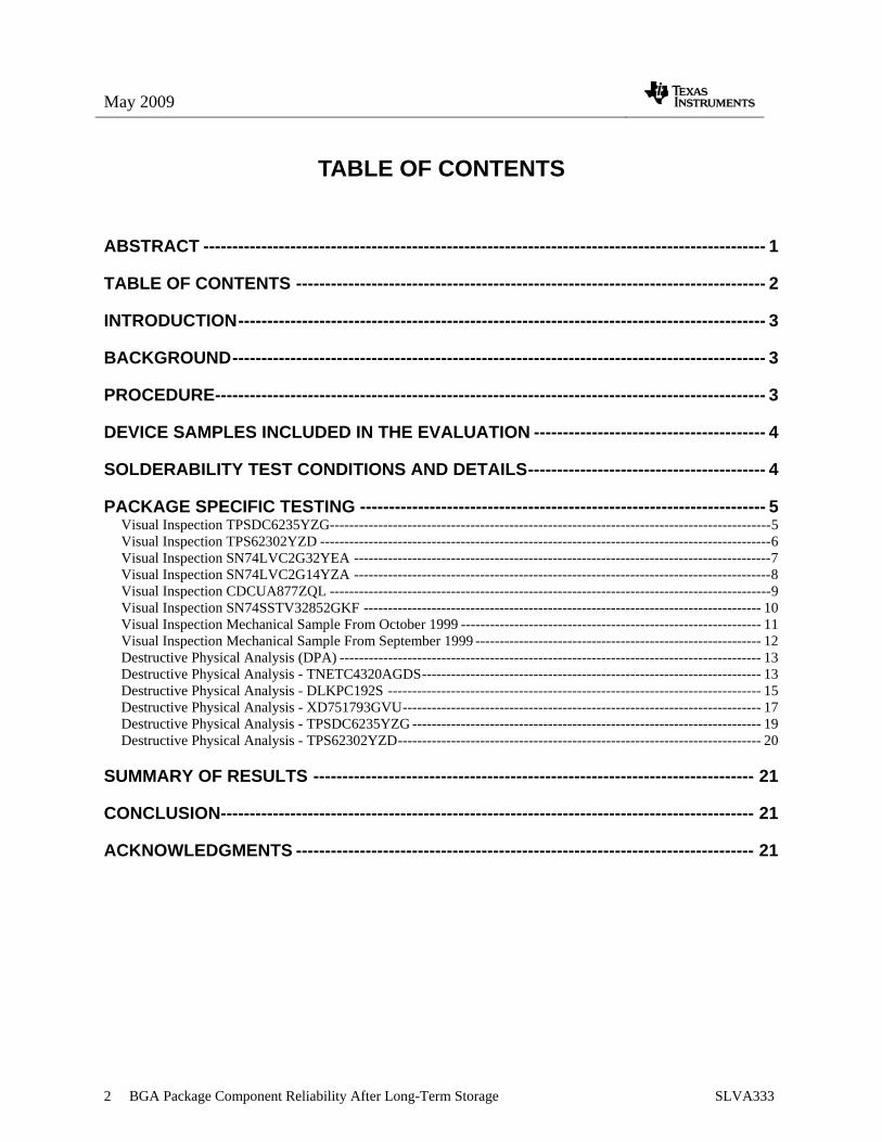
PACKAGE SPECIFIC TESTING VISUAL INSPECTION TPSDC6235YZG Bottom view – Units not soldered
Figure 3. Virgin Unit Figure 4. Unit After Steam Aging
Units placed on Test Board #45. SnAgCu solder paste for lead-free balls, peak temperature 240°C
Figure 5. Virgin Unit Figure 6. Steam Aging
Units placed on ceramic plate. SnAgCu solder paste for lead-free balls, peak temperature 240°C
Figure 7. Virgin Units Figure 8. Steam Aging

May 2009
6 BGA Package Component Reliability After Long-Term Storage SLVA333
VISUAL INSPECTION TPS62302YZD
Bottom view – Units not soldered
Figure 9. Virgin Unit Figure 10. Unit After Steam Aging
Units placed on Test Board #45. SnAgCu solder paste for lead-free balls, peak temperature 240°C
Figure 11. Virgin Unit Figure 12. Steam Aging
Units placed on ceramic plate. SnAgCu solder paste for lead-free balls, peak temperature 240°C
Figure 13. Virgin Units Figure 14. Steam-Aging

May 2009
7 BGA Package Component Reliability After Long-Term Storage SLVA333
VISUAL INSPECTION SN74LVC2G32YEA
Bottom view – Units not soldered
Figure 15. Virgin Unit Figure 16. Unit After Steam-Aging
Units placed on Test Board #41. SnAgCu solder paste for lead-free balls, peak temperature 240°C
Figure 17. Virgin Unit Figure 18. Steam-Aging
Units placed on ceramic plate. SnAgCu solder paste for lead free balls, peak temperature 240°C
Figure 19. Virgin Unit Figure 20. Steam-Aging

May 2009
8 BGA Package Component Reliability After Long-Term Storage SLVA333
VISUAL INSPECTION SN74LVC2G14YZA
Bottom view – Units not soldered
Figure 21. Virgin Unit Figure 22. Unit After Steam-Aging
Units placed on Test Board #41. SnPb solder paste for non lead-free balls, peak temperature 220°C
Figure 23. Virgin Unit Figure 24. Steam-Aging
Units placed on ceramic plate. SnPb solder paste for non lead-free balls, peak temperature 220°C
Figure 25. Virgin Units Figure 26. Steam-Aging
May 2009
9 BGA Package Component Reliability After Long-Term Storage SLVA333
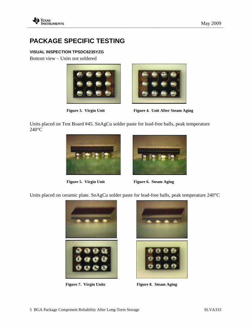
VISUAL INSPECTION CDCUA877ZQL Bottom view – Units not soldered (Originally, some balls were not populated on the package.)
Figure 27. Virgin Unit Figure 28. Unit After Steam-Aging Units placed on Test Board #56. SnAgCu solder paste for lead-free balls, peak temperature 240°C
Figure 29. Virgin Units Figure 30. Steam-Aging
Units placed on ceramic plate. SnAgCu solder paste for lead-free balls, peak temperature 240°C (Originally, some balls were not populated on the package.)
Figure 31. Virgin Units Figure 32. Steam-Aging

May 2009
10 BGA Package Component Reliability After Long-Term Storage SLVA333
VISUAL INSPECTION SN74SSTV32852GKF
Bottom view – Units not soldered
Figure 33. Virgin Units Figure 34. Units After Steam-Aging
Units placed on Test Board #56. SnPb solder paste for non lead-free balls, peak temperature 220°C
Figure 35. Virgin Unit Figure 36. Steam-Aging
Units placed on ceramic plate. SnPb solder paste for non lead-free balls, peak temperature 220°C
Figure 37. Virgin Units Figure 38. Steam-Aging
May 2009
11 BGA Package Component Reliability After Long-Term Storage SLVA333
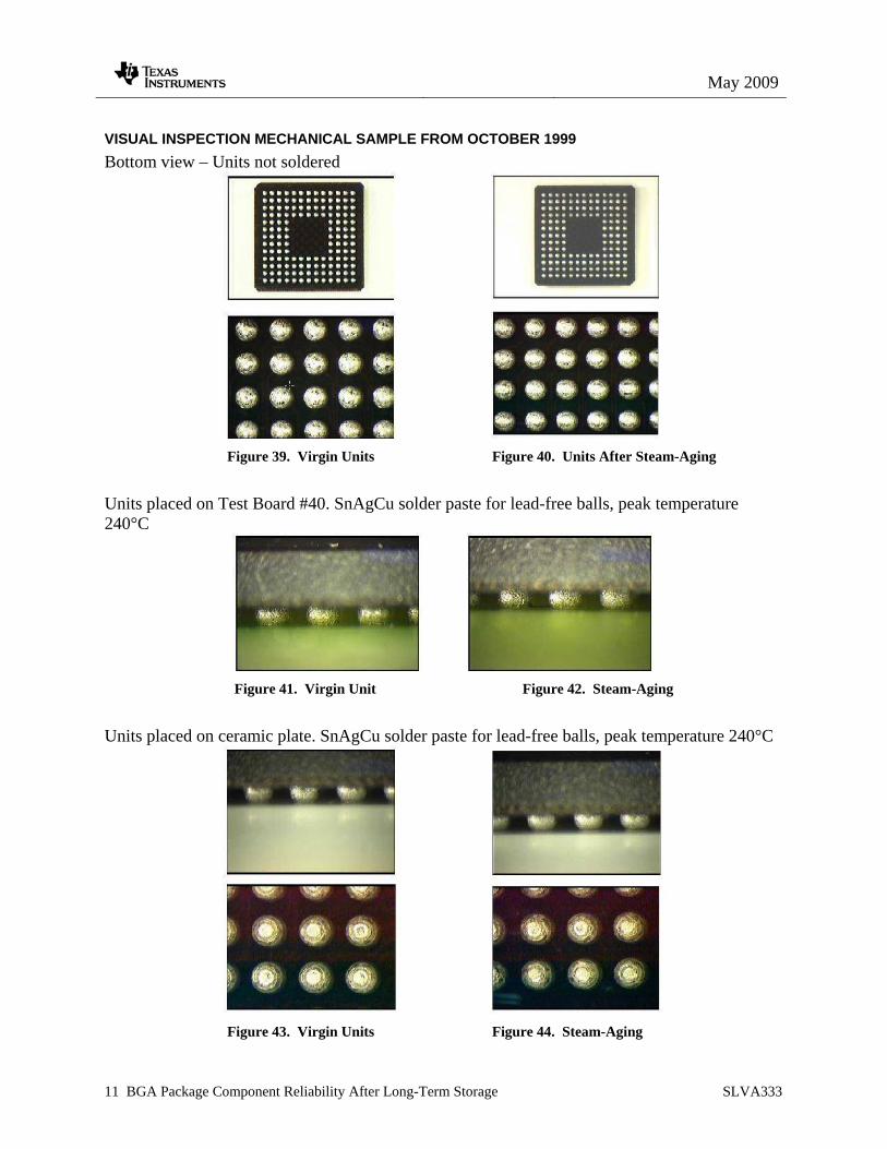
VISUAL INSPECTION MECHANICAL SAMPLE FROM OCTOBER 1999 Bottom view – Units not soldered
Figure 39. Virgin Units Figure 40. Units After Steam-Aging
Units placed on Test Board #40. SnAgCu solder paste for lead-free balls, peak temperature 240°C
Figure 41. Virgin Unit Figure 42. Steam-Aging
Units placed on ceramic plate. SnAgCu solder paste for lead-free balls, peak temperature 240°C
Figure 43. Virgin Units Figure 44. Steam-Aging

May 2009
12 BGA Package Component Reliability After Long-Term Storage SLVA333
VISUAL INSPECTION MECHANICAL SAMPLE FROM SEPTEMBER 1999 Bottom view – Units not soldered
Figure 45. Virgin Units Figure 46. Units After Steam-Aging
Units placed on Test Board #40. SnPb solder paste for non lead-free balls, peak temperature 220°C
Figure 47. Virgin Unit Figure 48. Steam-Aging
Units placed on ceramic plate. SnPb solder paste for non lead-free balls, peak temperature 220°C
Figure 49. Virgin Units Figure 50. Steam-Aging

May 2009
13 BGA Package Component Reliability After Long-Term Storage SLVA333
DESTRUCTIVE PHYSICAL ANALYSIS (DPA) Some of the package samples collected for this study have been further investigated for any signs of aging or other environmental influence during the extended storage time. Besides in-depth optical inspection under the microscope, electron microscopy and cross-sectioning through the package were performed at a solder ball attach location.
DESTRUCTIVE PHYSICAL ANALYSIS - TNETC4320AGDS Microscopic image of large BGA package not soldered. Manufactured: 2004 DPA performed at TI Tucson
Figure 51. Virgin Unit Figure 52. Virgin Unit, Bottom View
Field Emission Scanning Electron Microscopy (FESEM) Micrograph of representative TNETC4320AGDS device solder balls.
Figure 53. Image of Solder Balls Figure 54. Detailed View

May 2009
14 BGA Package Component Reliability After Long-Term Storage SLVA333
FESEM Micrograph and Energy-Dispersive Spectroscopy (EDS) spectrum of representative TNETC4320AGDS device solder ball.
Figure 55. Detailed Image of Solder Ball
Figure 56. Element Analysis of the Solder Ball
Optical and FESEM micrograph of a representative TNETC4320AGDS device solder ball cross-section. No abnormalities were observed.
Figure 57 Microscopic View Figure 58. FESEM Image of Solder Ball Cross-section

May 2009
15 BGA Package Component Reliability After Long-Term Storage SLVA333
DESTRUCTIVE PHYSICAL ANALYSIS - DLKPC192S Microscopic image on large BGA package not soldered. Manufactured: 2002
Figure 59. Virgin Unit Figure 60. Virgin Unit - Bottom View
FESEM micrograph of representative DLKPC192S device solder balls.
Figure 61. Solder Ball View Figure 62. Detailed View
FESEM micrograph and EDS spectrum of a representative DLKPC192S device solder ball.
Figure 63. Solder Ball Detailed View

May 2009
16 BGA Package Component Reliability After Long-Term Storage SLVA333
Figure 64. Element Analysis of the Solder Ball
Optical micrograph and FESEM micrograph of a representative DLKPC192S device solder balls.
Figure 65. Microscopic View Figure 66. FESEM Image of Solder Ball Cross-
section

May 2009
17 BGA Package Component Reliability After Long-Term Storage SLVA333
DESTRUCTIVE PHYSICAL ANALYSIS - XD751793GVU
Microscopic image of large BGA package not soldered. Manufactured: 2004
Figure 67. Virgin Unit Figure 68. Virgin Unit - Bottom View
FESEM micrograph of representative XD751793GVU device solder balls.
Figure 69. Image of Solder Balls Figure 70. Detailed View
Figure 71. Detailed View - The visible
scratches on the ball surface are from
the electrical test socket contractor.

May 2009
18 BGA Package Component Reliability After Long-Term Storage SLVA333
EDS spectrum of a representative XD751793GVU device solder ball.
Figure 72. Element Analysis of the Solder Ball
Optical and FESEM micrograph of a representative XD751793GVU device solder ball cross-section.
Figure 73. Microscopic View Figure 74. FESEM Image View

May 2009
19 BGA Package Component Reliability After Long-Term Storage SLVA333
DESTRUCTIVE PHYSICAL ANALYSIS - TPSDC6235YZG Microscopic image of the investigated DSBGA package – Lead-free solder ball composition. Manufactured: June 2005
Figure 75. Microscopic View Figure 76. FESEM Image View
FESEM micrograph of representative TPSDC6235YZG device solder ball
Figure 77. Detailed View of Solder Ball
Microscopic view of TPSDC6235YZG cross-section
Figure 78. Solder Ball Cross-section View

May 2009
20 BGA Package Component Reliability After Long-Term Storage SLVA333
DESTRUCTIVE PHYSICAL ANALYSIS - TPS62302YZD Microscopic image of the investigated DSBGA package – Lead-free solder ball composition. Manufactured: April 2007
Figure 79. Microscopic View
FESEM micrograph of representative TPS62302YZD device solder balls
Figure 80. FESEM Image View
FESEM view of TPS62302 and Optical microscope cross-section
Figure 81. FESEM Image View Figure 82. Solder Ball Cross-section View

May 2009
21 BGA Package Component Reliability After Long-Term Storage SLVA333
SUMMARY OF RESULTS • No failure mechanisms have been identified that compromise the reliability of solder
bumped BGA packages stored for extended periods of time in a warehouse environment.
• Surface analysis of solder balls revealed expected elements. SEM and optical microscopy revealed nothing abnormal. No degradation of the solder balls was observed.
• Solderability of all devices met expectations and was indistinguishable from current
devices.
• All materials and internal interfaces of the solder ball structure revealed no anomalies.
CONCLUSION The shelf life of extended storage life devices as determined by solderability, SEM visual, SEM spectral analysis, cross-sectional analysis, and optical microscopy is greater than 10 years.
ACKNOWLEDGMENTS The authors wish to recognize the following individuals for their professional assistance:
• The TI Reliability Laboratory in Tucson, Arizona conducted DPA testing under the engineering guidance of Lucas Copeland.
• The TI Reliability Laboratory in Freising, Germany for the solderability test evaluations performed on the samples published in this report.
• Julie Terlisner compiled all photographs and text into this report format.

IMPORTANT NOTICETexas Instruments Incorporated and its subsidiaries (TI) reserve the right to make corrections, modifications, enhancements, improvements,and other changes to its products and services at any time and to discontinue any product or service without notice. Customers shouldobtain the latest relevant information before placing orders and should verify that such information is current and complete. All products aresold subject to TI’s terms and conditions of sale supplied at the time of order acknowledgment.TI warrants performance of its hardware products to the specifications applicable at the time of sale in accordance with TI’s standardwarranty. Testing and other quality control techniques are used to the extent TI deems necessary to support this warranty. Except wheremandated by government requirements, testing of all parameters of each product is not necessarily performed.TI assumes no liability for applications assistance or customer product design. Customers are responsible for their products andapplications using TI components. To minimize the risks associated with customer products and applications, customers should provideadequate design and operating safeguards.TI does not warrant or represent that any license, either express or implied, is granted under any TI patent right, copyright, mask work right,or other TI intellectual property right relating to any combination, machine, or process in which TI products or services are used. Informationpublished by TI regarding third-party products or services does not constitute a license from TI to use such products or services or awarranty or endorsement thereof. Use of such information may require a license from a third party under the patents or other intellectualproperty of the third party, or a license from TI under the patents or other intellectual property of TI.Reproduction of TI information in TI data books or data sheets is permissible only if reproduction is without alteration and is accompaniedby all associated warranties, conditions, limitations, and notices. Reproduction of this information with alteration is an unfair and deceptivebusiness practice. TI is not responsible or liable for such altered documentation. Information of third parties may be subject to additionalrestrictions.Resale of TI products or services with statements different from or beyond the parameters stated by TI for that product or service voids allexpress and any implied warranties for the associated TI product or service and is an unfair and deceptive business practice. TI is notresponsible or liable for any such statements.TI products are not authorized for use in safety-critical applications (such as life support) where a failure of the TI product would reasonablybe expected to cause severe personal injury or death, unless officers of the parties have executed an agreement specifically governingsuch use. Buyers represent that they have all necessary expertise in the safety and regulatory ramifications of their applications, andacknowledge and agree that they are solely responsible for all legal, regulatory and safety-related requirements concerning their productsand any use of TI products in such safety-critical applications, notwithstanding any applications-related information or support that may beprovided by TI. Further, Buyers must fully indemnify TI and its representatives against any damages arising out of the use of TI products insuch safety-critical applications.TI products are neither designed nor intended for use in military/aerospace applications or environments unless the TI products arespecifically designated by TI as military-grade or "enhanced plastic." Only products designated by TI as military-grade meet militaryspecifications. Buyers acknowledge and agree that any such use of TI products which TI has not designated as military-grade is solely atthe Buyer's risk, and that they are solely responsible for compliance with all legal and regulatory requirements in connection with such use.TI products are neither designed nor intended for use in automotive applications or environments unless the specific TI products aredesignated by TI as compliant with ISO/TS 16949 requirements. Buyers acknowledge and agree that, if they use any non-designatedproducts in automotive applications, TI will not be responsible for any failure to meet such requirements.Following are URLs where you can obtain information on other Texas Instruments products and application solutions:Products ApplicationsAmplifiers amplifier.ti.com Audio www.ti.com/audioData Converters dataconverter.ti.com Automotive www.ti.com/automotiveDLP® Products www.dlp.com Broadband www.ti.com/broadbandDSP dsp.ti.com Digital Control www.ti.com/digitalcontrolClocks and Timers www.ti.com/clocks Medical www.ti.com/medicalInterface interface.ti.com Military www.ti.com/militaryLogic logic.ti.com Optical Networking www.ti.com/opticalnetworkPower Mgmt power.ti.com Security www.ti.com/securityMicrocontrollers microcontroller.ti.com Telephony www.ti.com/telephonyRFID www.ti-rfid.com Video & Imaging www.ti.com/videoRF/IF and ZigBee® Solutions www.ti.com/lprf Wireless www.ti.com/wireless
Mailing Address: Texas Instruments, Post Office Box 655303, Dallas, Texas 75265Copyright © 2009, Texas Instruments Incorporated