Embed Size (px)
Citation preview
BICYCLE REFLECTOR PROJECT
Celestine T. Kiss, M.A., Engineering Psychologist, Directorate for Engineering SciencesU.S. Consumer Product Safety Commission. USA
Mark Kumagai, Mechanical Engineer, PE, Directorate for Engineering SciencesU.S. Consumer Product Safety Commission, USA
Deborah K. Tinsworth, Directorate for Directorate for EpidemiologyU.S. Consumer Product Safety Commission, USA
Suzanne P. Cassidy, Directorate for Directorate for EpidemiologyU.S. Consumer Product Safety Commission, USA
Sandra Inkster, Ph. D., Directorate for Directorate for Health SciencesU.S. Consumer Product Safety Commission, USA
Scott Snyder, Directorate for Engineering SciencesU.S. Consumer Product Safety Commission, USA
John R. Murphy, Jr, Directorate for Engineering SciencesU.S. Consumer Product Safety Commission, USA
Thomas Schroeder, Directorate for Directorate for EpidemiologyU.S. Consumer Product Safety Commission, USA
Correspondence to: Mark Kumagai U.S. Consumer Product Safety CommissionDirectorate for Engineering Sciences4330 East West Highway, Bethesda, MD 20814-4408301-504-0494 x1237, Fax (301) 504-0079E-mail: [email protected]
Footnote: The views and opinions expressed are those of the authors and not necessarily theviews of the Commission. Since the authors wrote the article in their official capacity, it is in thepublic domain and may be freely copied or reprinted.
i
Table of Contents Page
I. Introduction…………………………………………………………………………. 1
II. Hazard Analysis…………………………………………………………………….. 2
III. Existing Standards ……………………………………….………………………… 3
IV. Bicycle Reflector Operation and Technology…………………...…………………. 4
V. Field Study Methodology…………………………………………………………... 7
VI. Results and Discussion……………………………………………………………... 14
VII. Conclusions…………………………………………………………………………. 18
VIII. Recommendations…………………………………..………………………..……... 19
References………………………………………………………………………………..…. 20
Figures
Figure 1: Retroreflector Design………………………………………………………. 4
Figure 2: Observation and Entrance Angle…………………………………………... 5
Figure 3: Evolution of the Bicycle Reflector………………………………………… 6
Figure 4: Schematic of Test Track…………………………………………………… 8
Figure 5: Daylight View of Parallel Path Location…………………………………... 9
Figure 6: Nighttime View of Parallel Path Location ………………………………… 9
Figure 7: Schematic of the Crossing Path Tests……………………………………… 10
Figure 8: Daylight View of the Crossing Path Test Location………………………... 10
Figure 9: Nighttime View of Crossing Path Test Location…………………………... 10
Tables
Table 1: Field Study Parallel Path Treatments……………………………………... 12
Table 2: Field Study Crossing Path Treatments……………………………………. 13
Table 3: Parallel Path Mean Detection and Recognition Distances and StandardDeviation by Treatment in Descending Order by Detection……………… 15
Table 4: Crossing Path Mean Detection and Recognition Distances and StandardDeviation by Treatment in Descending Order by Detection……………… 16
ii
Acknowledgments
This project could not have been done without the tireless efforts and cooperation of manyindividuals. We would like to thank them and express our sincerely appreciation for all of their hard work.
• John B. Arens, Manager of Photometric & Visibility Laboratory, Turner-FairbankHighway Research Center, Federal Highway Administration (FHWA). Mr. Arens'expertise and use of the FHWA's facilities to perform reflector measurement, headlightalignment and field luminance measurements were vital to the project. His guidance andpatient education of the CPSC staff in the science of photometry was greatly appreciated.
• Carol Tan Esse, Highway Research Engineer, Turner-Fairbank Highway Research Center,Federal Highway Administration (FHWA). Ms. Esse's sponsored studies and dataprovided the foundation for the hazard analysis.
• Marvin Levy. Ph.D., Research Psychologist, National Highway Traffic SafetyAdministration (NHTSA). Dr. Levy’s understanding, experience and desire to improve bicycle and pedestrian safety was important to this and future projects
• Richard D. Blomberg, President of Dunlap and Associates, Inc. Mr. Blomberg's review ofand suggestions for the field test plan, procedures, analysis and participation in publicmeetings was essential in implementing this project.
• Helmut T. Zwahlen, Ph.D., Russ Professor, Ohio University. Dr. Zwahlen's experience infield testing, photometric measurements, and general consultation was invaluable.
• National Institute of Standards and Technology (NIST). To the NIST police and all theemployees who encountered inconveniences because of the field-testing we extend a heartythank you for your patience and cooperation.
• Ann Weinstein and Area Wide Market Research, Inc. staff for supplying the test subjects.
• Chet Bacon, 3M corporation, for providing prototype test treatments.
• Thomas Prehn, representing Cateye, for providing reflectors and lights for testing.
• Mike Rood, Sate-Lite, for providing prototype and production reflectors for testing.
• Nelson Caballero and Richard Schenck at CPSC's Engineering Laboratory for developingthe electronic controller for the crossing path experiment.
- 1 -
I. Introduction
The bicycle safety requirements in 16 Code of Federal Regulations (CFR) Part 1512,developed by the U.S. Consumer Product Safety Commission (CPSC), became effective in 1976[1]. The section specifically addressing reflectors is defined in 16 CFR Part 1512.16. It requiresthat bicycles be equipped with reflective devices to permit recognition and identification underillumination from motor vehicle headlamps. The regulation includes mechanical and photometricrequirements, and testing techniques for front, rear, side and pedal reflectors.
In June 1994, the CPSC published a report, Bicycle Use and Hazard Patterns in theUnited States [2]. This report was based on 1991 nationwide surveys that collected informationon bicycle-related injuries and characteristics and use patterns of the general population ofbicyclists. The study revealed that a large disproportionate share of deaths occurred at night,strongly indicating that riding after dark is more hazardous than riding during the day. During1994, the National Highway Traffic Safety Administration (NHTSA) reported that 802 bicyclistsdied in crashes with motor vehicles. About 320 of these deaths (40 percent) occurred during non-daylight conditions, although a 1993 CPSC study indicated that only 12 percent of U.S. bicyclistsride after dark [3,4]. CPSC staff has estimated that riding after dark is about four times riskierthan riding during the day [5].
In November 1994, the CPSC sponsored a conference on nighttime bicycle safety toexplore ways of reducing the risks of nighttime riding. The conference brought together 50distinguished bicycle experts from around the country, representing the scientific community,industry, user groups, and all levels of government. The conference focused on the role of bicyclelighting, reflectors and consumer education in reducing nighttime riding risks. Participantsagreed to work with the CPSC to make bicycle riding safer, and to begin a voluntary standard forbicycle lighting. Participants also supported a CPSC project to evaluate current CPSC reflectorrequirements.
In June 1995, the Commission approved the Bicycle Reflector Project. The objective ofthe project was to evaluate the current CPSC reflector requirements, and determine if they couldbe improved. In March 1996, the CPSC staff hosted a public meeting to discuss the projectobjectives and invite participants to contribute suggestions and reflector products to be used infield-testing. The project scope was refined to reflect input received.
The Bicycle Reflector Project consisted of three major efforts: (1) an analysis of theincident data to determine the hazard scenarios for bicycle and motor vehicle crashes thatoccurred during non-daylight conditions; (2) an investigation and selection of reflective treatmentsthat could potentially improve bicycle nighttime conspicuity; and (3) a controlled field test ofdriver detection and recognition of existing and prototype reflectors. This study also examinedone type of combination light/reflector.
- 2 -
II. Hazard Analysis
The CPSC staff analyzed available information on nighttime bicycle/motor vehicleincidents. The purpose of the analysis was to develop hazard patterns that could be used toevaluate the current CPSC reflector requirements. This information was obtained primarily fromfour data sources:
(1) NHTSA Fatal Accident Reporting System (FARS) [3];(2) Pedestrian and Bicycle Crash Types of the Early 1990's [6],(3) Bicycle Crash Types: A 1990's Informational Guide [7]; and(4) A Study of Bicycle/Motor-Vehicle Accidents: Identification of Problem Types and
Countermeasures Approaches [8].
The FARS data provided general information about light conditions, victims, motorists, androadways involved in fatal crashes. The other three sources provided further details aboutcircumstances involved in fatal and non-fatal incidents.
In 1994, NHTSA reported that 802 pedalcyclists (primarily bicyclists) died in the UnitedStates in crashes involving motor vehicles [3]. About 320 or 40%, of these fatalities occurredduring non-daylight conditions, which are dusk, night, and dawn. Sixty percent of the non-daylight fatalities involved pedalcyclists over age 25. About one-half (51 percent) of themotorists involved in fatal non-daylight incidents were ages 25-44 years. More than half of theincidents involved alcohol use by either the motorist and/or the cyclist. The median posted speedlimit on roads on which fatal, non-daylight incidents occurred was 40 miles per hour, and overone-fourth of the fatalities occurred on roadways with posted speed limits of 55 miles per hour orgreater. However, the actual speed of the vehicle at the time of the incident was not known.
The University of North Carolina's Highway Safety Research Center studied about 3000bicycle/motor vehicle crashes from six states in the early 1990s [6, 7]. "Crossing path" and"parallel path" crash types accounted for about 53% and 40% of the non-daylight incidents,respectively. Crossing path crash types were defined as incidents that occurred at intersections,driveways, and other junctions when the bicyclist crossed the path of the motorist. Parallel pathcrash types were defined as incidents that occurred when bicyclist and motorist were approachingon parallel paths, either heading in the same or opposite directions.
Cross and Fisher studied over 900 bicycle/motor vehicle incidents that occurred in fourareas of the United States in 1975 [8]. This study identified a major nighttime "problem type"that involved motorists overtaking a bicyclist because they failed to see the bicyclist in time toavoid the crash. This scenario occurred more frequently at night than during the day. In thesecases, 63 percent of the non-fatal incidents and 71 percent of the fatal incidents occurred duringdarkness.
- 3 -
III. Existing Standards
In the United States, most bicycles are required to be sold with reflectors that meet themandatory requirement, 16 CFR 1512.16. The regulation requires bicycles to be equipped withreflective devices to permit recognition and identification under illumination from motor vehicleheadlamps. Bicycles are required to have a red rear-facing reflector; an essentially colorless front-facing reflector; and amber or essentially colorless pedal reflectors. These reflectors are intendedto provide increased visibility of the bicycle for motorists approaching the bicycle from both therear and the front.
Bicycles are also required to have spoke-mounted side reflectors that are amber oressentially colorless for the front wheel and red or essentially colorless for the rear wheel. Reflective tire sidewalls or rims can be used instead of spoke reflectors. Most bicycles sold in theUnited States are equipped with the spoke reflectors rather than the reflective tire sidewalls. There are no spoke reflector load requirements, but reflective rim and tire sidewalls must resist anabrasion test.
Photometric performance requirements and testing techniques are also specified in 16 CFR1512.16. The regulation specifies minimum coefficients of luminous intensity ( RI) . Thecoefficient of luminous intensity is the measure of photometric performance as it relates to theperceived brightness of a reflector. A temperature and humidity cycling test for plastic reflectorsare also specified in 16 CFR 1512.16. This type of testing ensures the product does not degradedue to exposure to the outdoor environment.
European and Asian countries have developed reflector requirements based on 16 CFR1512.16. Reflective tire sidewalls are commonly used in some European countries, such as theNetherlands. Germany has standards for larger front and rear reflectors than CPSC's regulationreflectors. The reflector performance requirements in the International Standards Organization(ISO) 6742/2 Cycles - Lighting and Retro-reflective Devices - Photometric and PhysicalRequirements standard are the same as the CPSC requirements.
The CPSC's bicycle regulation does not require lights on bicycles sold in the UnitedStates. A 1990 review of state laws by the League of American Wheelmen, showed that all fiftystates require a front white light and a rear red reflector, but the laws are inconsistently enforced[9]. Many European countries require bicycles to have lights that meet or exceed ISO 6742-1,which is a voluntary standard that specifies the minimum photometric, color, mounting, andpower requirements for front and rear lighting.
- 4 -
IV. Bicycle Reflector Operation and Technology
Reflector Operation
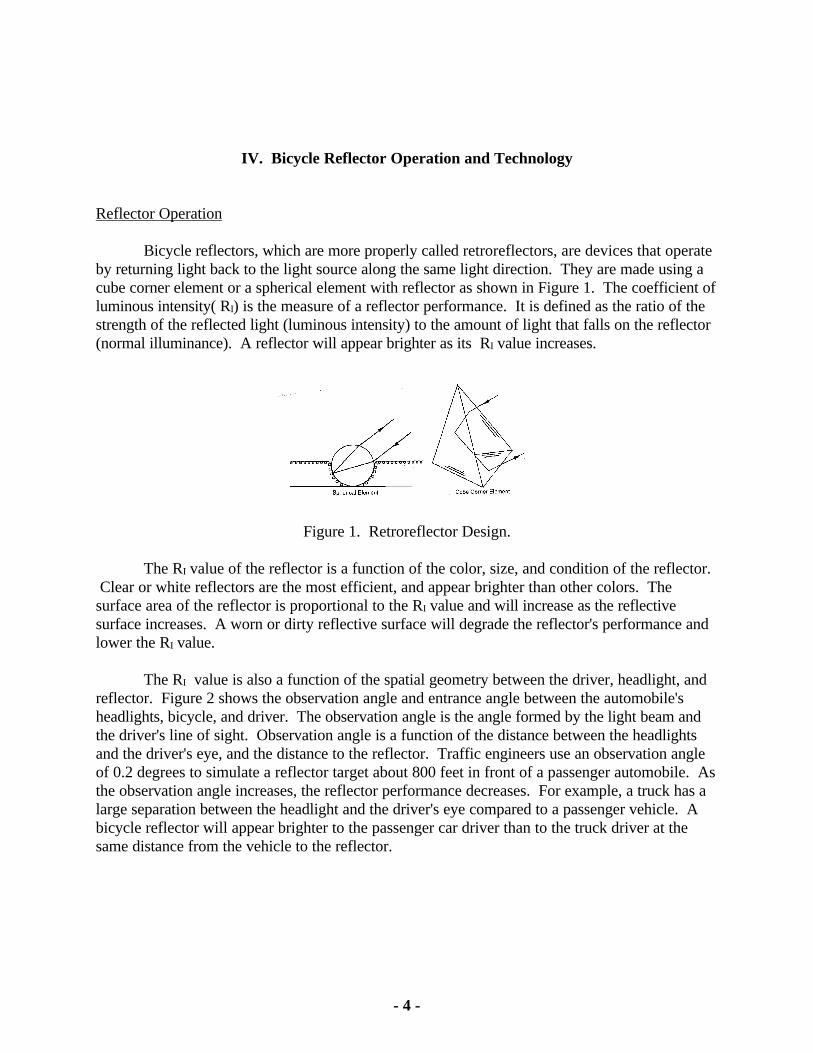
Bicycle reflectors, which are more properly called retroreflectors, are devices that operateby returning light back to the light source along the same light direction. They are made using acube corner element or a spherical element with reflector as shown in Figure 1. The coefficient ofluminous intensity( RI) is the measure of a reflector performance. It is defined as the ratio of thestrength of the reflected light (luminous intensity) to the amount of light that falls on the reflector(normal illuminance). A reflector will appear brighter as its RI value increases.
Figure 1. Retroreflector Design.
The RI value of the reflector is a function of the color, size, and condition of the reflector. Clear or white reflectors are the most efficient, and appear brighter than other colors. Thesurface area of the reflector is proportional to the RI value and will increase as the reflectivesurface increases. A worn or dirty reflective surface will degrade the reflector's performance andlower the RI value.
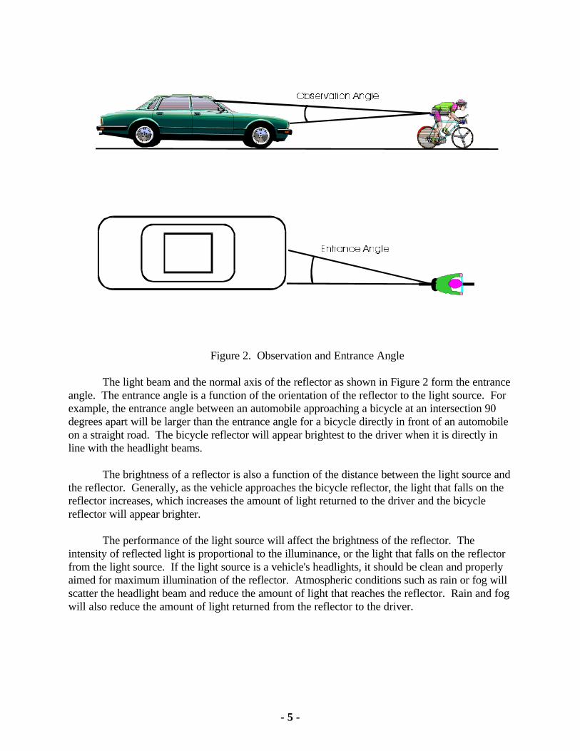
The RI value is also a function of the spatial geometry between the driver, headlight, andreflector. Figure 2 shows the observation angle and entrance angle between the automobile'sheadlights, bicycle, and driver. The observation angle is the angle formed by the light beam andthe driver's line of sight. Observation angle is a function of the distance between the headlightsand the driver's eye, and the distance to the reflector. Traffic engineers use an observation angleof 0.2 degrees to simulate a reflector target about 800 feet in front of a passenger automobile. Asthe observation angle increases, the reflector performance decreases. For example, a truck has alarge separation between the headlight and the driver's eye compared to a passenger vehicle. Abicycle reflector will appear brighter to the passenger car driver than to the truck driver at thesame distance from the vehicle to the reflector.
- 5 -
Figure 2. Observation and Entrance Angle
The light beam and the normal axis of the reflector as shown in Figure 2 form the entranceangle. The entrance angle is a function of the orientation of the reflector to the light source. Forexample, the entrance angle between an automobile approaching a bicycle at an intersection 90degrees apart will be larger than the entrance angle for a bicycle directly in front of an automobileon a straight road. The bicycle reflector will appear brightest to the driver when it is directly inline with the headlight beams.
The brightness of a reflector is also a function of the distance between the light source andthe reflector. Generally, as the vehicle approaches the bicycle reflector, the light that falls on thereflector increases, which increases the amount of light returned to the driver and the bicyclereflector will appear brighter.
The performance of the light source will affect the brightness of the reflector. Theintensity of reflected light is proportional to the illuminance, or the light that falls on the reflectorfrom the light source. If the light source is a vehicle's headlights, it should be clean and properlyaimed for maximum illumination of the reflector. Atmospheric conditions such as rain or fog willscatter the headlight beam and reduce the amount of light that reaches the reflector. Rain and fogwill also reduce the amount of light returned from the reflector to the driver.
- 6 -
Reflector Technology
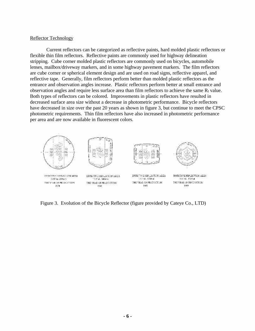
Current reflectors can be categorized as reflective paints, hard molded plastic reflectors orflexible thin film reflectors. Reflective paints are commonly used for highway delineationstripping. Cube corner molded plastic reflectors are commonly used on bicycles, automobilelenses, mailbox/driveway markers, and in some highway pavement markers. The film reflectorsare cube corner or spherical element design and are used on road signs, reflective apparel, andreflective tape. Generally, film reflectors perform better than molded plastic reflectors as theentrance and observation angles increase. Plastic reflectors perform better at small entrance andobservation angles and require less surface area than film reflectors to achieve the same RI value. Both types of reflectors can be colored. Improvements in plastic reflectors have resulted indecreased surface area size without a decrease in photometric performance. Bicycle reflectorshave decreased in size over the past 20 years as shown in figure 3, but continue to meet the CPSCphotometric requirements. Thin film reflectors have also increased in photometric performanceper area and are now available in fluorescent colors.
Figure 3. Evolution of the Bicycle Reflector (figure provided by Cateye Co., LTD)
- 7 -
V. Field Study Methodology
A. Background
A 1978 study by McGee, Decision Sight Distance for Highway Design and TrafficControl Requirements [11] describes a model of a driver’s perception based on his/her’s ability todetect, recognize, and react to a hazard. McGee defined detection time as the period from onsetof the hazard (stimulus) to the moment when the image of the hazard is "registered on the brain. Recognition occurs when the driver can identify the object, and decision occurs when the driveridentifies alternative actions based on driving experience and knowledge. The response occurswhen the driver applies the vehicle controls such as removing the foot from the accelerator to stepon the brake or to initiate steering. The final component is the evasive or corrective maneuversuch as a change in speed and/or path. McGee’s study led to the formulation of a model toquantify the sight distances based on the driver's perception and reaction process. He used thismodel to develop Decision Sight Distance (DSD) tables to provide guidelines for designers ofhighways, and traffic control devices.
Researchers have argued that detection and recognition are not equally important in thedriving process. Some researchers believe that increasing the target's detection distances withoutincreasing the recognition distances may be of little safety value and may be a distraction [12]. For example, if a driver detects a target, he expects to recognize it in a reasonable time. If he orshe can not recognize it, the driver may ignore the target having incorrectly concluded that thetarget is stationary and not a hazard. During daylight hours, drivers receive visual cues, such ascolor and shape that assist them in identifying objects. However, during non-daylight hours visualcues are greatly reduced, colors are less distinguishable, and field of vision is dependent on carheadlights or street lighting. Because of these limitations, drivers' preview times arecompromised.
Bicycle reflectors are crash avoidance safety devices intended to increase bicycleconspicuity. As part of this project, hazard scenarios were studied to evaluate situations in whichreflectors might be more effective if changes were made to their design. For example, in asituation where a motorist is overtaking a bicycle from the rear, would improving the reflectorsprovide the driver more reaction time and help avoid a collision? In another situation, where abicyclist and motorist are approaching an intersection from perpendicular directions, wouldimproving the reflectors allow the motorist to notice the bicycle sooner? In these potential crashsituations, improving the bicycle's conspicuity could reduce the number of nighttime bicycleincidents. If a new or modified bicycle reflector system could be detected and recognized atsignificantly greater distances than the reflector currently required by the CPSC regulations, thenthere maybe a way to reduce the number of nighttime riding incidents.
The CPSC staff was not aware of any quantifiable correlation between photometricperformance and a motorist's ability to see and avoid a hazard. Therefore, laboratory photometrictesting alone could not be used to evaluate a bicycle reflector system. The most feasibleevaluation would be to compare the relative performance of the reflectors that met the CPSC
- 8 -
regulation to other types of bicycle conspicuity treatments through field-testing. The Directoratefor Engineering Sciences, Division of Human Factors (ESHF), developed a field test methodologysimilar to a 1984 study conducted by R. D. Blomberg, A. Hale, & D. F. Preusser, Ph.D., for theNational Highway Traffic Safety Administration (NHTSA)[13].
B. Overview
The objective of the field study was to compare the performance of various bicyclereflectors and or light systems (hereafter referred to as "treatments") to the CPSC reflectorregulation. This was done by measuring detection and recognition responses for subjects as theydrove a vehicle through a roadway system. Testing was conducted on the campus of the NationalInstitute of Standards and Technology (NIST). The campus provided dark and lighted streets,crossing roadways, and background visual clutter such as building lights and traffic on roadwaysnear the facilities. This setting simulated a typical neighborhood environment and a dark ruralenvironment.
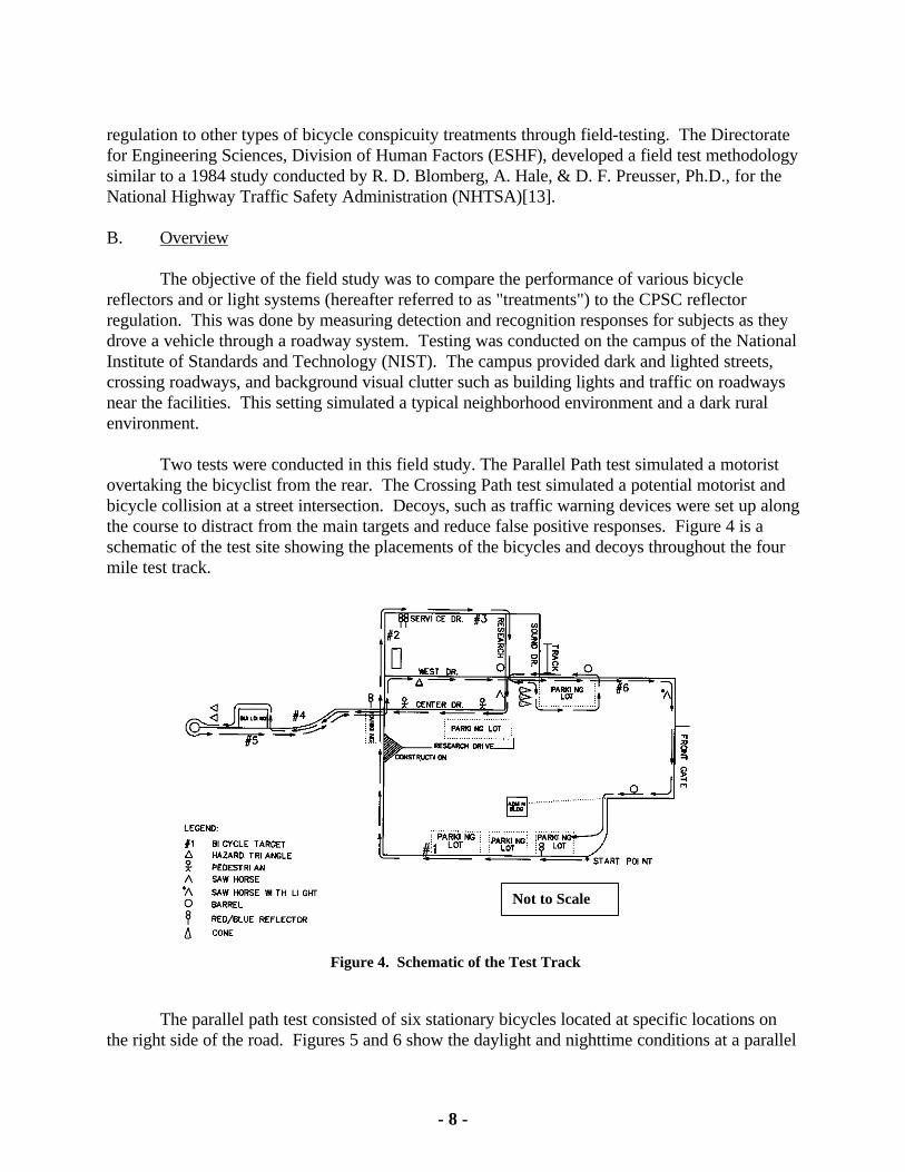
Two tests were conducted in this field study. The Parallel Path test simulated a motoristovertaking the bicyclist from the rear. The Crossing Path test simulated a potential motorist andbicycle collision at a street intersection. Decoys, such as traffic warning devices were set up alongthe course to distract from the main targets and reduce false positive responses. Figure 4 is aschematic of the test site showing the placements of the bicycles and decoys throughout the fourmile test track.
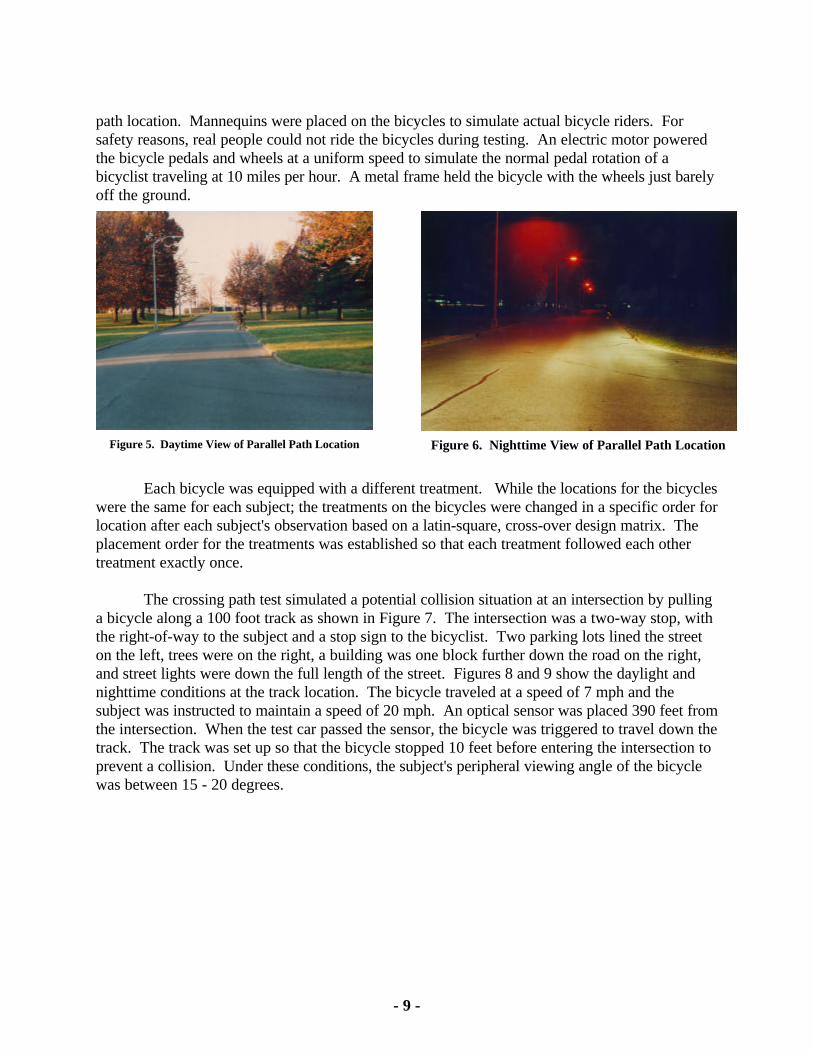
The parallel path test consisted of six stationary bicycles located at specific locations onthe right side of the road. Figures 5 and 6 show the daylight and nighttime conditions at a parallel
Not to Scale
Figure 4. Schematic of the Test Track
- 9 -
path location. Mannequins were placed on the bicycles to simulate actual bicycle riders. Forsafety reasons, real people could not ride the bicycles during testing. An electric motor poweredthe bicycle pedals and wheels at a uniform speed to simulate the normal pedal rotation of abicyclist traveling at 10 miles per hour. A metal frame held the bicycle with the wheels just barelyoff the ground.
Each bicycle was equipped with a different treatment. While the locations for the bicycleswere the same for each subject; the treatments on the bicycles were changed in a specific order forlocation after each subject's observation based on a latin-square, cross-over design matrix. Theplacement order for the treatments was established so that each treatment followed each othertreatment exactly once.
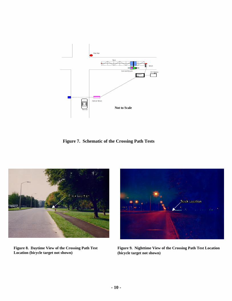
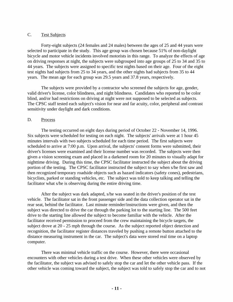
The crossing path test simulated a potential collision situation at an intersection by pullinga bicycle along a 100 foot track as shown in Figure 7. The intersection was a two-way stop, withthe right-of-way to the subject and a stop sign to the bicyclist. Two parking lots lined the streeton the left, trees were on the right, a building was one block further down the road on the right,and street lights were down the full length of the street. Figures 8 and 9 show the daylight andnighttime conditions at the track location. The bicycle traveled at a speed of 7 mph and thesubject was instructed to maintain a speed of 20 mph. An optical sensor was placed 390 feet fromthe intersection. When the test car passed the sensor, the bicycle was triggered to travel down thetrack. The track was set up so that the bicycle stopped 10 feet before entering the intersection toprevent a collision. Under these conditions, the subject's peripheral viewing angle of the bicyclewas between 15 - 20 degrees.
Figure 5. Daytime View of Parallel Path Location Figure 6. Nighttime View of Parallel Path Location
- 10 -
Figure 7. Schematic of the Crossing Path Tests
Not to Scale
Figure 8. Daytime View of the Crossing Path TestLocation (bicycle target not shown)
Figure 9. Nighttime View of the Crossing Path Test Location (bicycle target not shown)
Optical Sensor
24 V Battery
Winch
Cart and Bicycle
ControlBox
Test Car
Track
Stop Sign
- 11 -
C. Test Subjects
Forty-eight subjects (24 females and 24 males) between the ages of 25 and 44 years wereselected to participate in the study. This age group was chosen because 51% of non-daylightbicycle and motor vehicle incidents involved motorists in this range. To analyze the effects of ageon driving responses at night, the subjects were subgrouped into age groups of 25 to 34 and 35 to44 years. The subjects were assigned to specific test nights based on their age. Four of the eighttest nights had subjects from 25 to 34 years, and the other nights had subjects from 35 to 44years. The mean age for each group was 29.5 years and 37.8 years, respectively.
The subjects were provided by a contractor who screened the subjects for age, gender,valid driver's license, color blindness, and night blindness. Candidates who reported to be colorblind, and/or had restrictions on driving at night were not supposed to be selected as subjects. The CPSC staff tested each subject's vision for near and far acuity, color, peripheral and contrastsensitivity under daylight and dark conditions.
D. Process
The testing occurred on eight days during period of October 22 - November 14, 1996. Six subjects were scheduled for testing on each night. The subjects' arrivals were at 1 hour 45minutes intervals with two subjects scheduled for each time period. The first subjects werescheduled to arrive at 7:00 p.m. Upon arrival, the subjects' consent forms were submitted, theirdriver's licenses were examined and their license number was recorded. The subjects were thengiven a vision screening exam and placed in a darkened room for 20 minutes to visually adapt fornighttime driving. During this time, the CPSC facilitator instructed the subject about the drivingportion of the testing. The CPSC facilitator instructed the subject to say when s/he first saw andthen recognized temporary roadside objects such as hazard indicators (safety cones), pedestrians,bicyclists, parked or standing vehicles, etc. The subject was told to keep talking and telling thefacilitator what s/he is observing during the entire driving time.
After the subject was dark adapted, s/he was seated in the driver's position of the testvehicle. The facilitator sat in the front passenger side and the data collection operator sat in therear seat, behind the facilitator. Last minute reminder/instructions were given, and then thesubject was directed to drive the car through the parking lot to the starting line. The 500 feetdrive to the starting line allowed the subject to become familiar with the vehicle. After thefacilitator received permission to proceed from the crew maintaining the bicycle targets, thesubject drove at 20 - 25 mph through the course. As the subject reported object detection andrecognition, the facilitator register distances traveled by pushing a remote button attached to thedistance measuring instrument in the car. The subject's data were stored real time on a laptopcomputer.
There was minimal vehicle traffic on the course. However, there were occasionalencounters with other vehicles during a test drive. When these other vehicles were observed bythe facilitator, the subject was advised to safely stop the car and let the other vehicle pass. If theother vehicle was coming toward the subject, the subject was told to safely stop the car and to not
- 12 -
look at the oncoming headlights. While preventing or limiting glare due to oncoming trafficcreates an ideal situation, this was necessary in order to avoid an additional variable in the testing. At the end of the drive, the purpose of the testing was described to the subject. The subject wasgiven an opportunity to comment on the experiment.
E. Treatment Selection
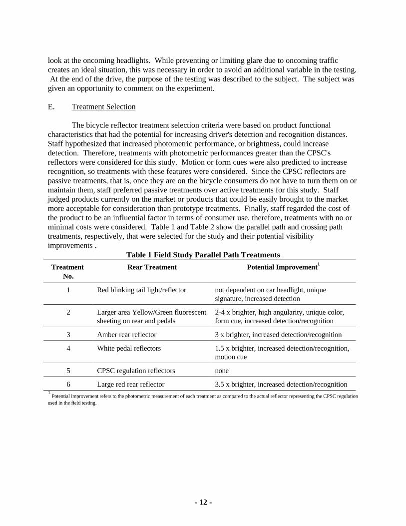
The bicycle reflector treatment selection criteria were based on product functionalcharacteristics that had the potential for increasing driver's detection and recognition distances. Staff hypothesized that increased photometric performance, or brightness, could increasedetection. Therefore, treatments with photometric performances greater than the CPSC'sreflectors were considered for this study. Motion or form cues were also predicted to increaserecognition, so treatments with these features were considered. Since the CPSC reflectors arepassive treatments, that is, once they are on the bicycle consumers do not have to turn them on ormaintain them, staff preferred passive treatments over active treatments for this study. Staffjudged products currently on the market or products that could be easily brought to the marketmore acceptable for consideration than prototype treatments. Finally, staff regarded the cost ofthe product to be an influential factor in terms of consumer use, therefore, treatments with no orminimal costs were considered. Table 1 and Table 2 show the parallel path and crossing pathtreatments, respectively, that were selected for the study and their potential visibilityimprovements .
Table 1 Field Study Parallel Path Treatments
Treatment No.
Rear Treatment Potential Improvement1
1 Red blinking tail light/reflector not dependent on car headlight, uniquesignature, increased detection
2 Larger area Yellow/Green fluorescentsheeting on rear and pedals
2-4 x brighter, high angularity, unique color,form cue, increased detection/recognition
3 Amber rear reflector 3 x brighter, increased detection/recognition
4 White pedal reflectors 1.5 x brighter, increased detection/recognition,motion cue
5 CPSC regulation reflectors none
6 Large red rear reflector 3.5 x brighter, increased detection/recognition1 Potential improvement refers to the photometric measurement of each treatment as compared to the actual reflector representing the CPSC regulation
used in the field testing.
- 13 -
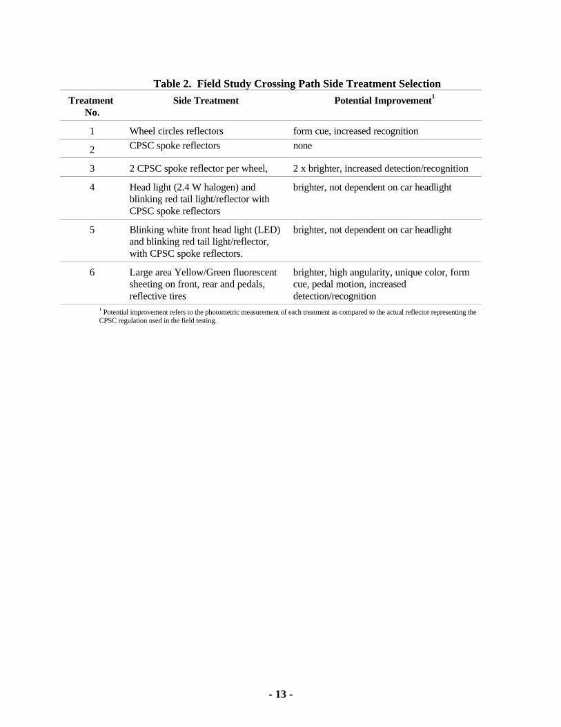
Table 2. Field Study Crossing Path Side Treatment Selection
Treatment No.
Side Treatment Potential Improvement1
1 Wheel circles reflectors form cue, increased recognition
2 CPSC spoke reflectors none
3 2 CPSC spoke reflector per wheel, 2 x brighter, increased detection/recognition
4 Head light (2.4 W halogen) andblinking red tail light/reflector withCPSC spoke reflectors
brighter, not dependent on car headlight
5 Blinking white front head light (LED)and blinking red tail light/reflector,with CPSC spoke reflectors.
brighter, not dependent on car headlight
6 Large area Yellow/Green fluorescentsheeting on front, rear and pedals,reflective tires
brighter, high angularity, unique color, formcue, pedal motion, increaseddetection/recognition
1 Potential improvement refers to the photometric measurement of each treatment as compared to the actual reflector representing theCPSC regulation used in the field testing.
- 14 -
VI. Results and Discussion
CPSC staff performed the field test data analysis using statistical techniques to determinethe effects of each factor on the outcome of the experiment. Staff was primarily interested witheffects of the treatments on detection and recognition distances. Particularly, determining if themean detection or recognition distance of a target was statistically significantly different thanCPSC standard reflector target (Target 5).
This study was conducted with primed subjects, that is, they were instructed and preparedto see "temporary roadside objects." Therefore, the results for the detection and recognitiondistances should be viewed as better than the average unsuspecting driver. In addition, thesubjects were driving at a low speed (approximately 20-25 mph), which allowed them more timeto scan the driving environment. Finally, the subjects were instructed to scan the environment andgive a running commentary of what they were observing. All these factors prepared the subjectsin this study to be more aware of their driving environment. However, the subjects did not knowexactly when or where a "target" would appear. In addition, they were aware of conditions (i.e.,animals, pedestrians, and other vehicles) on the course that were beyond the control of thefacilitator and, therefore, they had to drive with caution.
A. Vision Screening Results for Subjects
All the subjects met the study entrance criteria for at least 20/40 binocular distancephotopic acuity. Four did not meet the requirements of the Maryland Motor VehicleAdministration for 20/40 distance acuity when each individual eye was tested. There was adecrease in acuity under reduced light conditions that was more noticeable in the older subjects. Two subjects were found to be color blind. Originally it was thought that because treatmentsvaried by color, color blind individuals might have difficulty identifying colors, but that was notfound to be the case for these two individuals, so their results were kept in the study.
B. Parallel Path Test Results
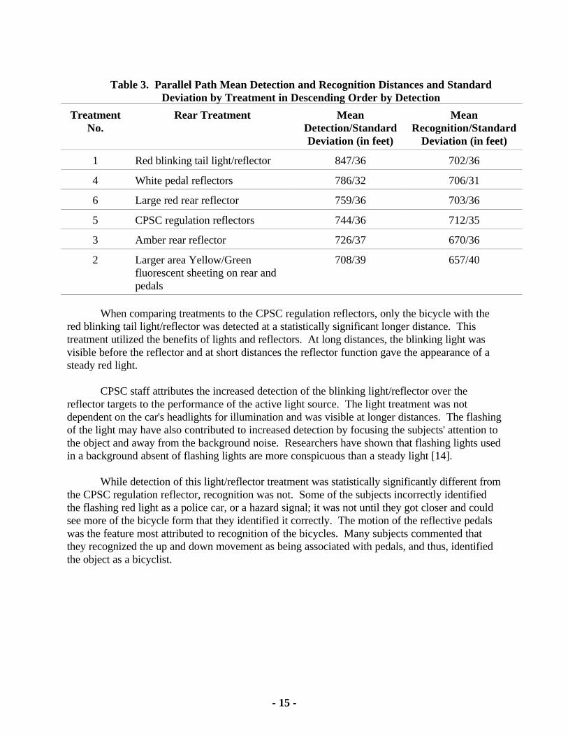
Location, target, and subject were found to be statistically significant for detectiondistances of the bicycles. The factors found to be significant for the recognition distances of thebicycles were location, test night, and subject. Table 3 shows the mean values and standarddeviation of the detection and recognition distances by target.
- 15 -
Table 3. Parallel Path Mean Detection and Recognition Distances and StandardDeviation by Treatment in Descending Order by Detection
TreatmentNo.
Rear Treatment MeanDetection/StandardDeviation (in feet)
MeanRecognition/Standard
Deviation (in feet)
1 Red blinking tail light/reflector 847/36 702/36
4 White pedal reflectors 786/32 706/31
6 Large red rear reflector 759/36 703/36
5 CPSC regulation reflectors 744/36 712/35
3 Amber rear reflector 726/37 670/36
2 Larger area Yellow/Greenfluorescent sheeting on rear andpedals
708/39 657/40
When comparing treatments to the CPSC regulation reflectors, only the bicycle with thered blinking tail light/reflector was detected at a statistically significant longer distance. Thistreatment utilized the benefits of lights and reflectors. At long distances, the blinking light wasvisible before the reflector and at short distances the reflector function gave the appearance of asteady red light.
CPSC staff attributes the increased detection of the blinking light/reflector over thereflector targets to the performance of the active light source. The light treatment was notdependent on the car's headlights for illumination and was visible at longer distances. The flashingof the light may have also contributed to increased detection by focusing the subjects' attention tothe object and away from the background noise. Researchers have shown that flashing lights usedin a background absent of flashing lights are more conspicuous than a steady light [14].
While detection of this light/reflector treatment was statistically significantly different fromthe CPSC regulation reflector, recognition was not. Some of the subjects incorrectly identifiedthe flashing red light as a police car, or a hazard signal; it was not until they got closer and couldsee more of the bicycle form that they identified it correctly. The motion of the reflective pedalswas the feature most attributed to recognition of the bicycles. Many subjects commented thatthey recognized the up and down movement as being associated with pedals, and thus, identifiedthe object as a bicyclist.
- 16 -
The mean detection distances for reflective treatments of the CPSC study were fairlyconsistent with the mean detection distances (approximately 800 feet) achieved in the studyconducted by Blomberg, et. al.[12]. However, the CPSC's mean recognition distances(approximately 700 feet) were much higher than for Blomberg's study (approximately 450 feet). In Blomberg's study, detection occurred roughly 400 feet before recognition for reflectivetreatments. In the CPSC study, the range between mean detection and recognition distances wasonly between 30 and 80 feet for reflective treatments.
The small distance between detection and recognition for the CPSC study as compared tothe Blomberg study is probably due to a critical difference in the nature of the subject's cognitivetask between the two studies. That is, the recognition task for CPSC subjects was less complexthan for the Blomberg subjects. Both studies placed decoys in the course. However, theidentification task for the subjects in the Blomberg study was more difficult because they had toidentify pedestrian as well as bicycle targets placed randomly on the driving course. Thismethodology is more conservative than CPSC's methodology, in which the subject's recognitiontask was only to recognize bicycles. Clearly, the cognitive processing time will be less for aCPSC subject who only has to decide whether the identified stimulus is a bicycle than the greaterprocessing time needed for a Blomberg subject who has to identified a stimulus as a pedestrian orbicycle.
C. Crossing Path Test Results
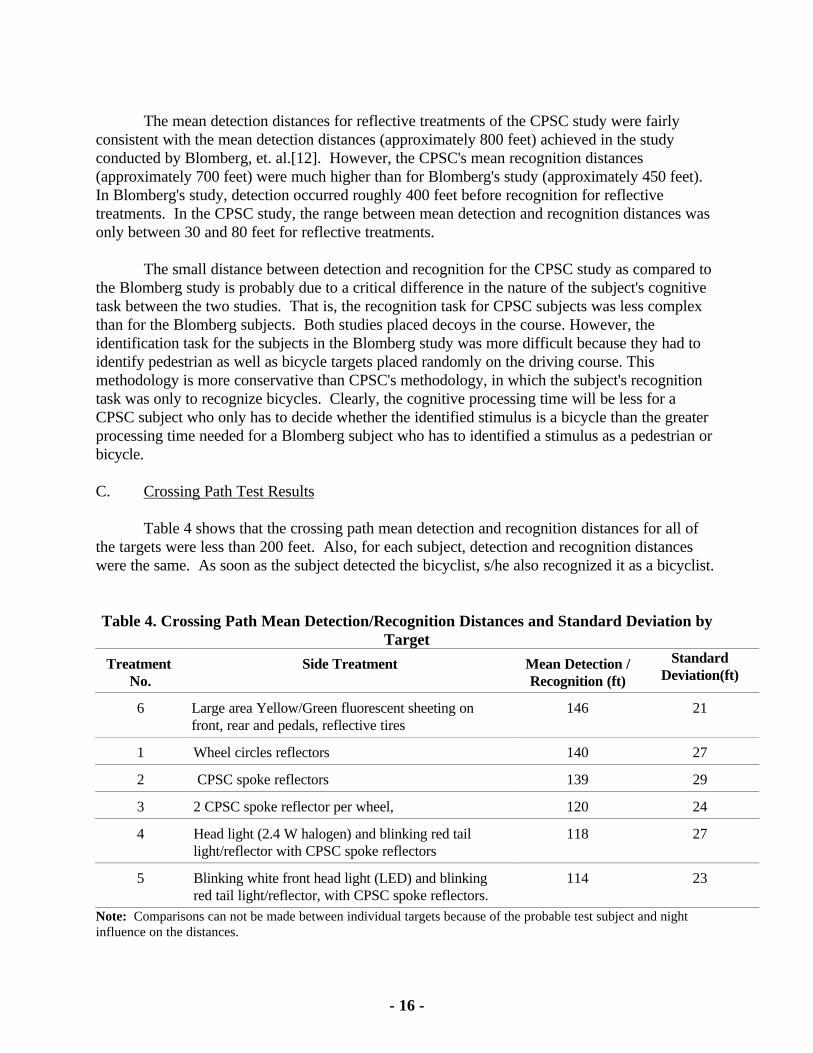
Table 4 shows that the crossing path mean detection and recognition distances for all ofthe targets were less than 200 feet. Also, for each subject, detection and recognition distanceswere the same. As soon as the subject detected the bicyclist, s/he also recognized it as a bicyclist.
Table 4. Crossing Path Mean Detection/Recognition Distances and Standard Deviation byTarget
Treatment No.
Side Treatment Mean Detection /Recognition (ft)
StandardDeviation(ft)
6 Large area Yellow/Green fluorescent sheeting onfront, rear and pedals, reflective tires
146 21
1 Wheel circles reflectors 140 27
2 CPSC spoke reflectors 139 29
3 2 CPSC spoke reflector per wheel, 120 24
4 Head light (2.4 W halogen) and blinking red taillight/reflector with CPSC spoke reflectors
118 27
5 Blinking white front head light (LED) and blinkingred tail light/reflector, with CPSC spoke reflectors.
114 23
Note: Comparisons can not be made between individual targets because of the probable test subject and nightinfluence on the distances.

- 17 -
Staff believes that the subjects did not detect the bicycle target until the vehicle was closeenough to illuminate the mannequin and bicycle. At that time, the subject immediately recognizedthe object as a bicyclist. Staff believes that the 15-20 degree viewing angle between the driverand bicycle and the background visual noise in this simulation contributed to the low detectionand recognition results. However, these conditions would be typical of many real street crossingsituations.
- 18 -
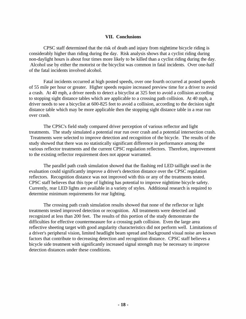
VII. Conclusions
CPSC staff determined that the risk of death and injury from nighttime bicycle riding isconsiderably higher than riding during the day. Risk analysis shows that a cyclist riding duringnon-daylight hours is about four times more likely to be killed than a cyclist riding during the day. Alcohol use by either the motorist or the bicyclist was common in fatal incidents. Over one-halfof the fatal incidents involved alcohol.
Fatal incidents occurred at high posted speeds, over one fourth occurred at posted speedsof 55 mile per hour or greater. Higher speeds require increased preview time for a driver to avoida crash. At 40 mph, a driver needs to detect a bicyclist at 325 feet to avoid a collision accordingto stopping sight distance tables which are applicable to a crossing path collision. At 40 mph, adriver needs to see a bicyclist at 600-825 feet to avoid a collision, according to the decision sightdistance table which may be more applicable then the stopping sight distance table in a rear runover crash.
The CPSC's field study compared driver perception of various reflector and lighttreatments. The study simulated a potential rear run over crash and a potential intersection crash. Treatments were selected to improve detection and recognition of the bicycle. The results of thestudy showed that there was no statistically significant difference in performance among thevarious reflector treatments and the current CPSC regulation reflectors. Therefore, improvementto the existing reflector requirement does not appear warranted.
The parallel path crash simulation showed that the flashing red LED taillight used in theevaluation could significantly improve a driver's detection distance over the CPSC regulationreflectors. Recognition distance was not improved with this or any of the treatments tested. CPSC staff believes that this type of lighting has potential to improve nighttime bicycle safety. Currently, rear LED lights are available in a variety of styles. Additional research is required todetermine minimum requirements for rear lighting.
The crossing path crash simulation results showed that none of the reflector or lighttreatments tested improved detection or recognition. All treatments were detected andrecognized at less than 200 feet. The results of this portion of the study demonstrate thedifficulties for effective countermeasure for a crossing path collision. Even the large areareflective sheeting target with good angularity characteristics did not perform well. Limitations ofa driver's peripheral vision, limited headlight beam spread and background visual noise are knownfactors that contribute to decreasing detection and recognition distance. CPSC staff believes abicycle side treatment with significantly increased signal strength may be necessary to improvedetection distances under these conditions.
- 19 -
VIII. Recommendations
Based on the above findings, the CPSC staff did not recommend amending the existingreflector requirements in 16 CFR Part 1512.16. Staff recommended conducting additionalresearch, testing, and evaluation of bicycle nighttime visibility. At a minimum, the research shouldlook to evaluate rear, front, and side lighting features that could possibly lead to a voluntarystandard. This testing and evaluation program could use techniques similar to the CPSC field testand should be performed with industry and other government agencies that have an interest infurthering the limited data on this subject.
According to representatives from the Federal Highway Administration (FHWA),research using ultra violet (UV) headlamps on automobiles to increase visibility is ongoing. Initialfield-testing showed an improvement in detection and recognition of pedestrians with lightcolored clothing and bicycles treated with fluorescent paint. NHTSA representatives reportedthat in Fiscal Year 1998, NHTSA awarded F&S of Blacksburg, Virginia, a Small BusinessInnovated Research (SBIR) contract to develop methods to substantially increase bicycle/cyclistconspicuity from all directions. The feasibility of prototype systems will be examined. NHTSA isalso conducting a literature review of research and other programs related to pedestrian andbicycle conspicuity. In FY 2000, NHTSA plans to develop and conduct a test and evaluationprogram to determine the effectiveness of various pedestrian and bicycle treatments.
- 20 -
References
[1] 16 CFR Section 1500.18 (a) Part 1512 - Requirements for Bicycles
[2] Rodgers, G.B., et al (1994) Bicycle Use and Hazard Patterns in the United States. U.S. ConsumerProduct Safety Commission, Washington, D.C.
[3] 1994 Fatal Accident Reporting System. National Highway Traffic Safety Administration,Washington,D.C.
[4] Rogers, Gregory B. "The Characteristics and Use Patterns of Bicycle Riders in the United States." Journal of Safety Research 25 (1994): 83-96 [5] Rogers, Gregory B. "Bicyclist Deaths and Fatality Risk Patterns." Accident Analysis and Prevention27 (1995): 215-223
[6] Hunter, W.W., Stutts, J.C., Pein, W.E., Cox, C.L., (1995) Pedestrian and Bicycle Crash Types of theEarly 1990's. FHWA-RD-95-163, Federal Highway Administration, Washington, D.C.
[7] Hunter, W.W., Stutts, J.C., Pein, W.E., Cox, C.L., (1995) Bicycle Crash Types: A 1990'sinformational Guide. Federal Highway Administration, Washington, D.C.
[8] Cross, K. D., Fisher, G., (1977) A Study of Bicycle/Motor-Vehicle Accidents: Identification ofProblem Types and Countermeasures Approaches. National Highway Traffic Safety Administration,Washington, D.C.
[9] The League of American Wheelmen (1990) "Lighting the Way Ahead" A special report on BicycleLighting and Night Riding.
[10] Burger, W.J., Smith, R.L., Ziedman, K., Mulholland, M.U., Bardales, M.C. and Sharkey, T.J."Improved Commercial Vehicle Conspicuity and Signaling Systems; Accident Analyses and FunctionalRequirements, March 1981, DOT-HS-806-100
[11] McGee, H.W., Moore, W., Knapp, B.G., and Sanders, J.H. (1978) Decision Sight Distance forHighway Design and Traffic Control Requirements DOT-FH-11-9278 U.S. Department ofTransportation, Federal Highway Administration, Washington, D.C.
[12] Bloom, R. F. (1976) Effectiveness of retroreflective treatments for pedestrians. St. Paul, MN:Final Report to the 3M Company.
[13] Blomberg, R. D., Hale, A., and Preusser, Ph.D., D. F. (1984) Conspicuity for Pedestrians andBicyclists: Definition of the Problem, Development and Test of Countermeasures. Dunlap andAssociates East, Inc., DTN H22-80-C-07052 Department of Transportation, National Highway TrafficSafety Administration, Washington, D.C.
[14] Crawford, A. The perception of light signals: The effect of mixing flashing and steady irrelevantlights. Ergonomics, 1963, 6(3), 287-294.