Embed Size (px)
Citation preview
IJSRST151518 | Received: 18 November 2015 | Accepted: 23 November 2015 | November-December 2015 [(1)5: 52-60]
© 2015 IJSRST | Volume 1 | Issue 5 | Print ISSN: 2395-6011 | Online ISSN: 2395-602X Themed Section: Engineering and Technology
52
Bidirectional Speed Control of DC Motor Based on Pulse Width Modulation using Microcontroller
Ayman Y. Yousef*1, M. H. Mostafa2 1Electrical Engineering Department, Faculty of Engineering at Shoubra, Benha University, Cairo, Egypt
2Distribution Sectors, South Cairo Electrical Distribution Co., Cairo, Egypt
ABSTRACT
This paper presents a design, simulation and implementation of Pulse Width Modulation (PWM) speed control
system of DC motor using microcontroller (MCU). The PIC16F877A microcontroller is programmed to generate
two periodic PWM signals from its Capture/Compare/PWM (CCP) modules. These output PWM signals from MCU
with various duty cycle are used to controlling the speed and direction of DC motor through L293D driver chip
which is used as an interface between MCU and DC motor. The PIC MCU has been programmed using flowcode
software package and the complete PWM control system model has been simulated using proteus design suite
software package. A hardware setup has been practically implemented for the proposed control system in order to
check the simulation results and which were acceptable and satisfactory.
Keywords: PIC Microcontroller, PWM Technique, CCP Module, Duty Cycle, DC Motor Driver.
I. INTRODUCTION
DC motor drives are used for many speed and position
control systems where their excellent performance, ease
of control and high efficiency are desirable
characteristics [1, 2]. The rotational speed of a DC
motor is directly proportional to the mean (average)
value of its supply voltage which applied to the motor
terminals and by increasing this value up to its
maximum value, the motor can rotate faster. Pulse-width
modulation (PWM) is a digital technique used in many
industrial applications mostly for controlling the motor
speed by varying the amount of power delivered to the
DC motor. In other words by increasing the voltage
applied to the motor its speed will increases.
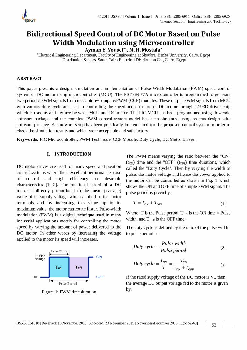
Figure 1: PWM time duration
The PWM means varying the ratio between the "ON"
(tON) time and the "OFF" (tOFF) time durations, which
called the "Duty Cycle". Then by varying the width of
pulse, the motor voltage and hence the power applied to
the motor can be controlled as shown in Fig. 1 which
shows the ON and OFF time of simple PWM signal. The
pulse period is given by:
(1)
Where: T is the Pulse period, TON is the ON time = Pulse
width, and TOFF is the OFF time.
The duty cycle is defined by the ratio of the pulse width
to pulse period as:
(2)
(3)
If the rated supply voltage of the DC motor is Vs, then
the average DC output voltage fed to the motor is given
by:
OFFON TTT
periodPulse
widthPulsecycleDuty
OFFON
ONON
TT
T
T
TcycleDuty
International Journal of Scientific Research in Science and Technology (www.ijsrst.com)
53
(4)
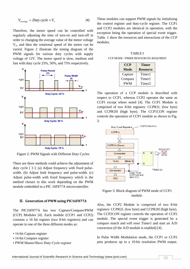
Therefore, the motor speed can be controlled with
regularly adjusting the time of turn-on and turn-off in
order to changing the average value of the motor voltage
Vav and then the rotational speed of the motor can be
varied. Figure 2 illustrate the timing diagram of the
PWM signals for various duty cycles with supply
voltage of 12V. The motor speed is slow, medium and
fast with duty cycle 25%, 50%, and 75% respectively.
Figure 2: PWM Signals with Different Duty Cycles
There are three methods could achieve the adjustment of
duty cycle [ 3 ]: (a) Adjust frequency with fixed pulse-
width. (b) Adjust both frequency and pulse-width. (c)
Adjust pulse-width with fixed frequency which is the
method chosen in this work depending on the PWM
module embedded in a PIC 16F877A microcontroller.
II. Generation of PWM using PIC16F877A
The PIC16F877A has two Capture/Compare/PWM
(CCP) Modules [4]. Each module (CCP1 and CCP2)
contains a 16 bit register (two 8-bit registers) and can
operate in one of the three different modes as:
• 16-bit Capture register
• 16-bit Compare register
• PWM Master/Slave Duty Cycle register
These modules can support PWM signals by initializing
the control register and duty-cycle register. The CCP1
and CCP2 modules are identical in operation, with the
exception being the operation of special event trigger.
Table. 1 show the resources and interactions of the CCP
modules.
TABLE I
CCP MODE -TIMER RESOURCES REQUIRED
CCP
Mode
Timer
Resource
Capture
Compare
PWM
Timer1
Timer1
Timer2
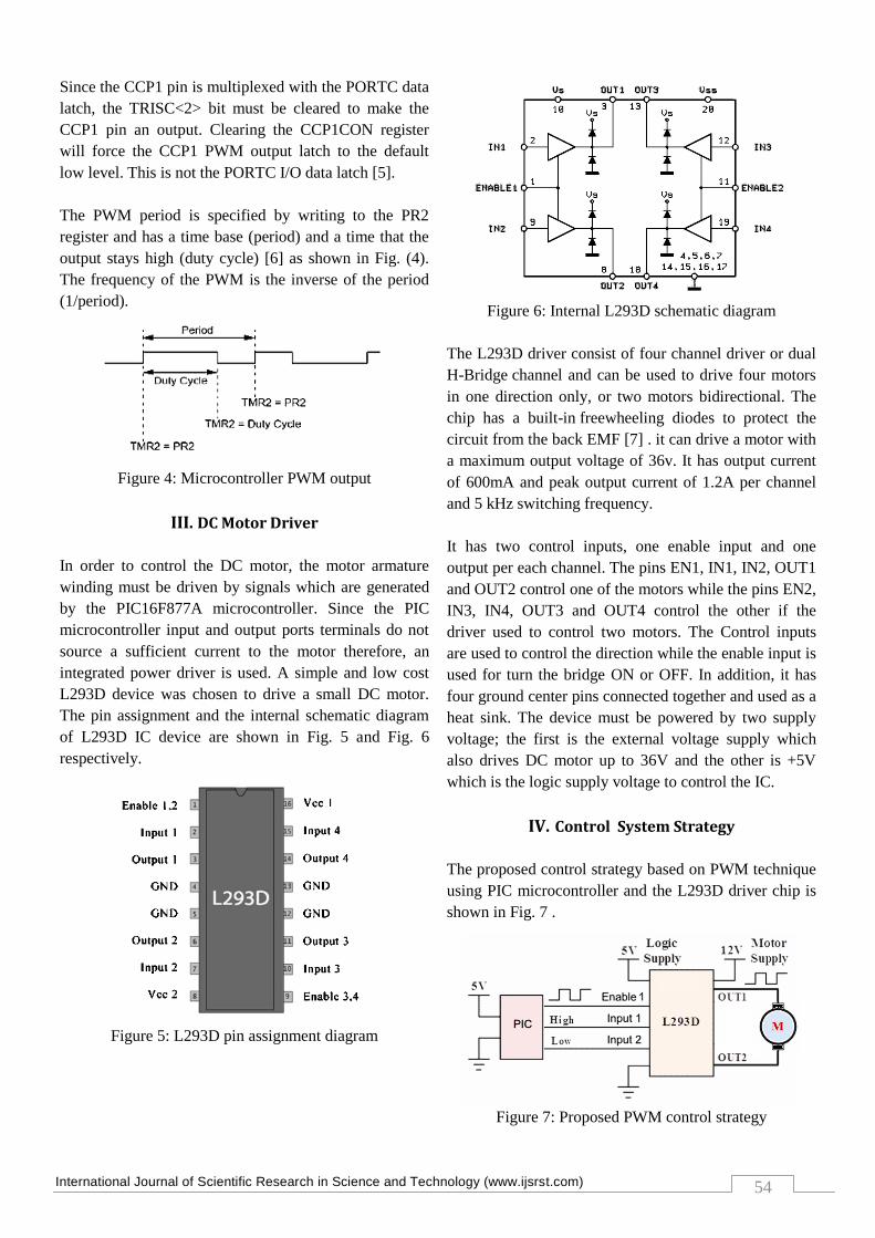
The operation of a CCP module is described with
respect to CCP1, whereas CCP2 operates the same as
CCP1 except where noted [4]. The CCP1 Module is
comprised of two 8-bit registers: CCPR1L (low byte)
and CCPR1H (high byte). The CCP1CON register
controls the operation of CCP1 module as shown in Fig.
3.
Figure 3: Block diagram of PWM mode of CCP1
module.
Also, the CCP2 Module is comprised of two 8-bit
registers: CCPR2L (low byte) and CCPR2H (high byte).
The CCP2CON register controls the operation of CCP2
module. The special event trigger is generated by a
compare match and will reset Timer1 and start an A/D
conversion (if the A/D module is enabled) [4].
In Pulse Width Modulation mode, the CCP1 or CCP2
pins produces up to a 10-bit resolution PWM output.
saverage VcycleDutyV
International Journal of Scientific Research in Science and Technology (www.ijsrst.com)
54
Since the CCP1 pin is multiplexed with the PORTC data
latch, the TRISC<2> bit must be cleared to make the
CCP1 pin an output. Clearing the CCP1CON register
will force the CCP1 PWM output latch to the default
low level. This is not the PORTC I/O data latch [5].
The PWM period is specified by writing to the PR2
register and has a time base (period) and a time that the
output stays high (duty cycle) [6] as shown in Fig. (4).
The frequency of the PWM is the inverse of the period
(1/period).
Figure 4: Microcontroller PWM output
III. DC Motor Driver
In order to control the DC motor, the motor armature
winding must be driven by signals which are generated
by the PIC16F877A microcontroller. Since the PIC
microcontroller input and output ports terminals do not
source a sufficient current to the motor therefore, an
integrated power driver is used. A simple and low cost
L293D device was chosen to drive a small DC motor.
The pin assignment and the internal schematic diagram
of L293D IC device are shown in Fig. 5 and Fig. 6
respectively.
Figure 5: L293D pin assignment diagram
Figure 6: Internal L293D schematic diagram
The L293D driver consist of four channel driver or dual
H-Bridge channel and can be used to drive four motors
in one direction only, or two motors bidirectional. The
chip has a built-in freewheeling diodes to protect the
circuit from the back EMF [7] . it can drive a motor with
a maximum output voltage of 36v. It has output current
of 600mA and peak output current of 1.2A per channel
and 5 kHz switching frequency.
It has two control inputs, one enable input and one
output per each channel. The pins EN1, IN1, IN2, OUT1
and OUT2 control one of the motors while the pins EN2,
IN3, IN4, OUT3 and OUT4 control the other if the
driver used to control two motors. The Control inputs
are used to control the direction while the enable input is
used for turn the bridge ON or OFF. In addition, it has
four ground center pins connected together and used as a
heat sink. The device must be powered by two supply
voltage; the first is the external voltage supply which
also drives DC motor up to 36V and the other is +5V
which is the logic supply voltage to control the IC.
IV. Control System Strategy
The proposed control strategy based on PWM technique
using PIC microcontroller and the L293D driver chip is
shown in Fig. 7 .
Figure 7: Proposed PWM control strategy
International Journal of Scientific Research in Science and Technology (www.ijsrst.com)
55
The operation of the H-Bridge is fairly simple by
Identify the logic state of Enable 1, Input 1, and Input 2
pins. Enable 1 pin is responsible for the motor turn on
and off, while the Input pins are used to change the
speed direction of the motor by changing the voltage
across its terminals. For example, if Enable 1, Input
1pins are in HIGH state, and Input 2 pin in the LOW
state, the motor will rotate clockwise. On the other hand,
if Enable 1, Input 2 pins are in HIGH state, and Input 1
pin in the LOW state, the motor will turn to the other
direction. If Input pins are both at the same level and the
Enable pin is high then the motor will stall (or break)
and with the Enable pin is low the motor will freewheel.
Therefore, the idea of the control depends upon the two
control inputs connected to the driver channel, when the
microcontroller sends a logic value 1 to the motor it will
start running in a certain direction, and when the logic
value is 0 it will inverse the direction. The behavior of
the DC motor for various input conditions are as in the
following truth table 2.
TABLE II
MOTOR BEHAVIOUR WITH VARIOUS INPUT CONDITIONS
Motor status Input 1 Input 2
Motor Stops or brake Low Low
Motor Runs
(Anticlockwise)
Low High
Motor Runs (clockwise) High Low
Stops or brake High High
V. PWM Control System Description
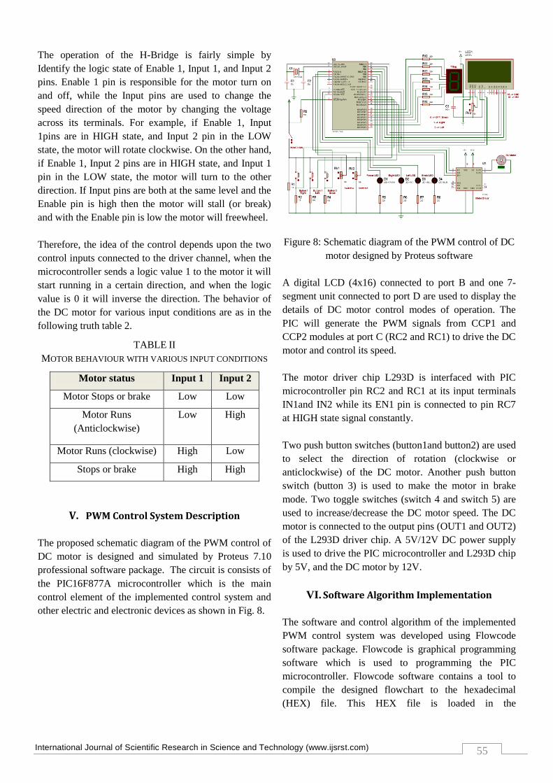
The proposed schematic diagram of the PWM control of
DC motor is designed and simulated by Proteus 7.10
professional software package. The circuit is consists of
the PIC16F877A microcontroller which is the main
control element of the implemented control system and
other electric and electronic devices as shown in Fig. 8.
Figure 8: Schematic diagram of the PWM control of DC
motor designed by Proteus software
A digital LCD (4x16) connected to port B and one 7-
segment unit connected to port D are used to display the
details of DC motor control modes of operation. The
PIC will generate the PWM signals from CCP1 and
CCP2 modules at port C (RC2 and RC1) to drive the DC
motor and control its speed.
The motor driver chip L293D is interfaced with PIC
microcontroller pin RC2 and RC1 at its input terminals
IN1and IN2 while its EN1 pin is connected to pin RC7
at HIGH state signal constantly.
Two push button switches (button1and button2) are used
to select the direction of rotation (clockwise or
anticlockwise) of the DC motor. Another push button
switch (button 3) is used to make the motor in brake
mode. Two toggle switches (switch 4 and switch 5) are
used to increase/decrease the DC motor speed. The DC
motor is connected to the output pins (OUT1 and OUT2)
of the L293D driver chip. A 5V/12V DC power supply
is used to drive the PIC microcontroller and L293D chip
by 5V, and the DC motor by 12V.
VI. Software Algorithm Implementation
The software and control algorithm of the implemented
PWM control system was developed using Flowcode
software package. Flowcode is graphical programming
software which is used to programming the PIC
microcontroller. Flowcode software contains a tool to
compile the designed flowchart to the hexadecimal
(HEX) file. This HEX file is loaded in the
International Journal of Scientific Research in Science and Technology (www.ijsrst.com)
56
microcontroller RAM in order to execute the control
system.
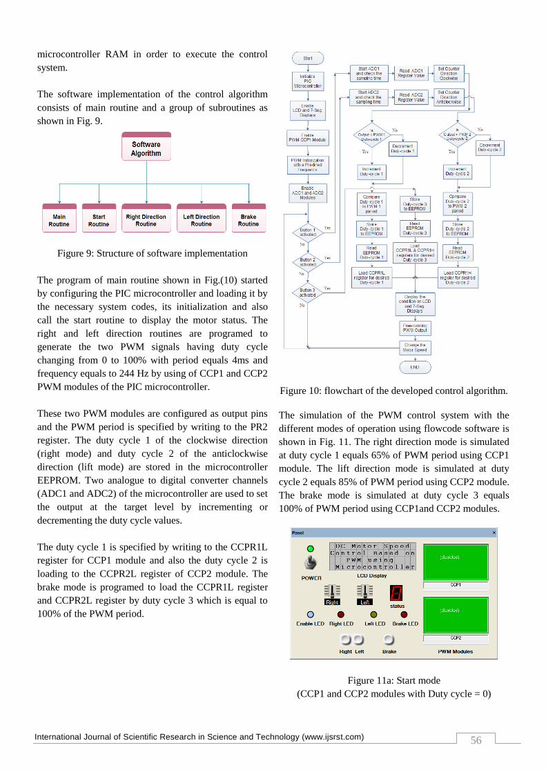
The software implementation of the control algorithm
consists of main routine and a group of subroutines as
shown in Fig. 9.
Figure 9: Structure of software implementation
The program of main routine shown in Fig.(10) started
by configuring the PIC microcontroller and loading it by
the necessary system codes, its initialization and also
call the start routine to display the motor status. The
right and left direction routines are programed to
generate the two PWM signals having duty cycle
changing from 0 to 100% with period equals 4ms and
frequency equals to 244 Hz by using of CCP1 and CCP2
PWM modules of the PIC microcontroller.
These two PWM modules are configured as output pins
and the PWM period is specified by writing to the PR2
register. The duty cycle 1 of the clockwise direction
(right mode) and duty cycle 2 of the anticlockwise
direction (lift mode) are stored in the microcontroller
EEPROM. Two analogue to digital converter channels
(ADC1 and ADC2) of the microcontroller are used to set
the output at the target level by incrementing or
decrementing the duty cycle values.
The duty cycle 1 is specified by writing to the CCPR1L
register for CCP1 module and also the duty cycle 2 is
loading to the CCPR2L register of CCP2 module. The
brake mode is programed to load the CCPR1L register
and CCPR2L register by duty cycle 3 which is equal to
100% of the PWM period.
Figure 10: flowchart of the developed control algorithm.
The simulation of the PWM control system with the
different modes of operation using flowcode software is
shown in Fig. 11. The right direction mode is simulated
at duty cycle 1 equals 65% of PWM period using CCP1
module. The lift direction mode is simulated at duty
cycle 2 equals 85% of PWM period using CCP2 module.
The brake mode is simulated at duty cycle 3 equals
100% of PWM period using CCP1and CCP2 modules.
Figure 11a: Start mode
(CCP1 and CCP2 modules with Duty cycle = 0)
International Journal of Scientific Research in Science and Technology (www.ijsrst.com)
57
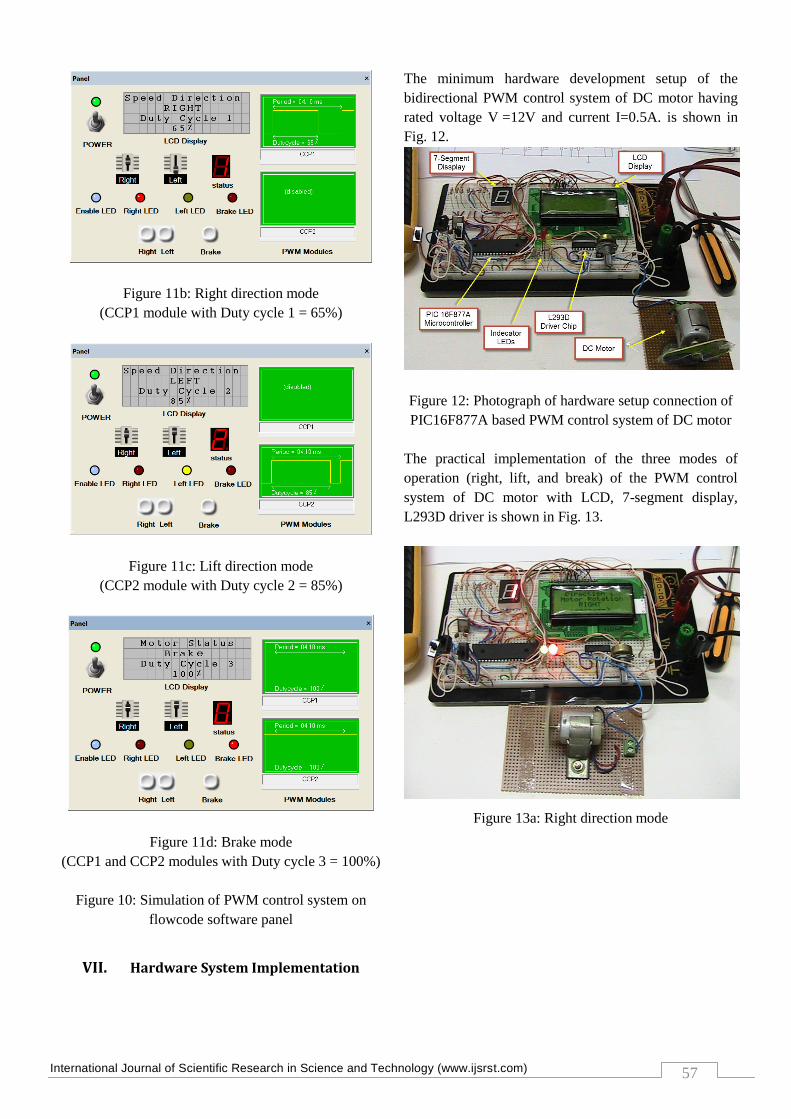
Figure 11b: Right direction mode
(CCP1 module with Duty cycle 1 = 65%)
Figure 11c: Lift direction mode
(CCP2 module with Duty cycle 2 = 85%)
Figure 11d: Brake mode
(CCP1 and CCP2 modules with Duty cycle 3 = 100%)
Figure 10: Simulation of PWM control system on
flowcode software panel
VII. Hardware System Implementation
The minimum hardware development setup of the
bidirectional PWM control system of DC motor having
rated voltage V =12V and current I=0.5A. is shown in
Fig. 12.
Figure 12: Photograph of hardware setup connection of
PIC16F877A based PWM control system of DC motor
The practical implementation of the three modes of
operation (right, lift, and break) of the PWM control
system of DC motor with LCD, 7-segment display,
L293D driver is shown in Fig. 13.
Figure 13a: Right direction mode
International Journal of Scientific Research in Science and Technology (www.ijsrst.com)
58
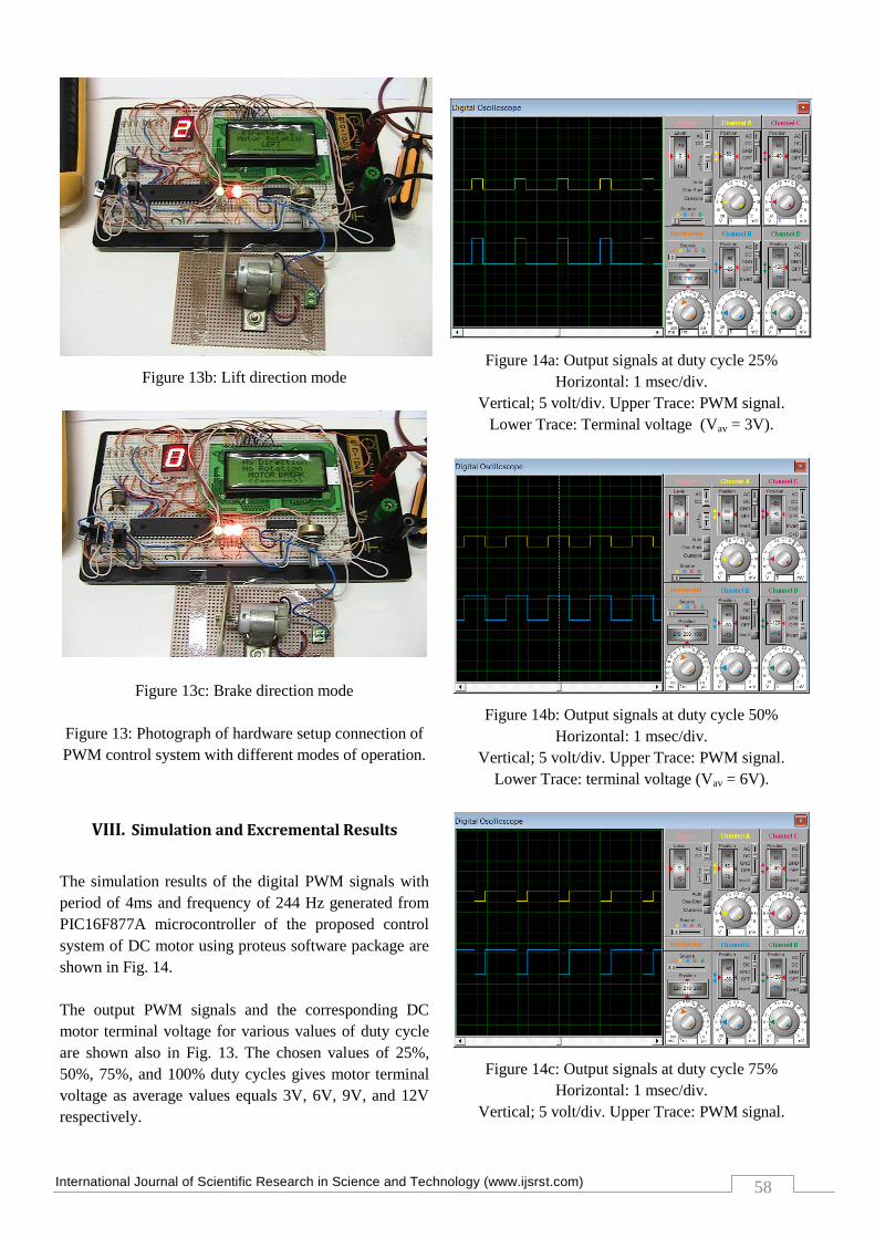
Figure 13b: Lift direction mode
Figure 13c: Brake direction mode
Figure 13: Photograph of hardware setup connection of
PWM control system with different modes of operation.
VIII. Simulation and Excremental Results
The simulation results of the digital PWM signals with
period of 4ms and frequency of 244 Hz generated from
PIC16F877A microcontroller of the proposed control
system of DC motor using proteus software package are
shown in Fig. 14.
The output PWM signals and the corresponding DC
motor terminal voltage for various values of duty cycle
are shown also in Fig. 13. The chosen values of 25%,
50%, 75%, and 100% duty cycles gives motor terminal
voltage as average values equals 3V, 6V, 9V, and 12V
respectively.
Figure 14a: Output signals at duty cycle 25%
Horizontal: 1 msec/div.
Vertical; 5 volt/div. Upper Trace: PWM signal.
Lower Trace: Terminal voltage (Vav = 3V).
Figure 14b: Output signals at duty cycle 50%
Horizontal: 1 msec/div.
Vertical; 5 volt/div. Upper Trace: PWM signal.
Lower Trace: terminal voltage (Vav = 6V).
Figure 14c: Output signals at duty cycle 75%
Horizontal: 1 msec/div.
Vertical; 5 volt/div. Upper Trace: PWM signal.
International Journal of Scientific Research in Science and Technology (www.ijsrst.com)
59
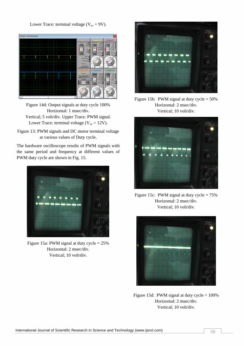
Lower Trace: terminal voltage (Vav = 9V).
Figure 14d: Output signals at duty cycle 100%
Horizontal: 1 msec/div.
Vertical; 5 volt/div. Upper Trace: PWM signal.
Lower Trace: terminal voltage (Vav = 12V).
Figure 13: PWM signals and DC motor terminal voltage
at various values of Duty cycle.
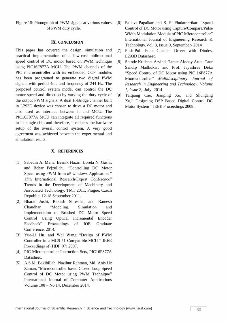
The hardware oscilloscope results of PWM signals with
the same period and frequency at different values of
PWM duty cycle are shown in Fig. 15.
Figure 15a: PWM signal at duty cycle = 25%
Horizontal: 2 msec/div.
Vertical; 10 volt/div.
Figure 15b: PWM signal at duty cycle = 50%
Horizontal: 2 msec/div.
Vertical; 10 volt/div.
Figure 15c: PWM signal at duty cycle = 75%
Horizontal: 2 msec/div.
Vertical; 10 volt/div.
Figure 15d: PWM signal at duty cycle = 100%
Horizontal: 2 msec/div.
Vertical; 10 volt/div.
International Journal of Scientific Research in Science and Technology (www.ijsrst.com)
60
Figure 15: Photograph of PWM signals at various values
of PWM duty cycle.
IX. CONCLUSION
This paper has covered the design, simulation and
practical implementation of a low-cost bidirectional
speed control of DC motor based on PWM technique
using PIC16F877A MCU. The PWM channels of the
PIC microcontroller with its embedded CCP modules
has been programed to generate two digital PWM
signals with period 4ms and frequency of 244 Hz. The
proposed control system model can control the DC
motor speed and direction by varying the duty cycle of
the output PWM signals. A dual H-Bridge channel built
in L293D device was chosen to drive a DC motor and
also used as interface between it and MCU. The
PIC16F877A MCU can integrate all required functions
in its single chip and therefore, it reduces the hardware
setup of the overall control system. A very good
agreement was achieved between the experimental and
simulation results.
X. REFERENCES
[1] Sabedin A. Meha, Besnik Haziri, Loreta N. Gashi,
and Behar Fejzullahu “Controlling DC Motor
Speed using PWM from c# windows Application ”
15th International Research/Expert Conference”
Trends in the Development of Machinery and
Associated Technology, TMT 2011, Prague, Czech
Republic, 12-18 September 2011.
[2] Bharat Joshi, Rakesh Shrestha, and Ramesh
Chaudhar “Modeling, Simulation and
Implementation of Brushed DC Motor Speed
Control Using Optical Incremental Encoder
Feedback” Proceedings of IOE Graduate
Conference, 2014.
[3] Yue-Li Hu, and Wei Wang “Design of PWM
Controller in a MCS-51 Compatible MCU ” IEEE
Proceedings of (HDP’07) 2007.
[4] PIC Microcontroller Instruction Sets, PIC16F877A
Datasheet.
[5] A.S.M. Bakibillah, Nazibur Rahman, Md. Anis Uz
Zaman, “Microcontroller based Closed Loop Speed
Control of DC Motor using PWM Technique”
International Journal of Computer Applications
Volume 108 – No 14, December 2014.
[6] Pallavi Papalkar and S. P. Phulambrikar, “Speed
Control of DC Motor using Capture/Compare/Pulse
Width Modulation Module of PIC Microcontroller”
International Journal of Engineering Research &
Technology,Vol. 3, Issue 9, September- 2014
[7] Push-Pull Four Channel Driver with Diodes,
L293D Datasheet.
[8] Shinde Krishnat Arvind, Tarate Akshay Arun, Taur
Sandip Madhukar, and Prof. Jayashree Deka
“Speed Control of DC Motor using PIC 16F877A
Microcontroller” Multidisciplinary Journal of
Research in Engineering and Technology, Volume
1, Issue 2, July- 2014
[9] Taiqiang Cao, Jianping Xu, and Shungang
Xu,“ Designing DSP Based Digital Control DC
Motor System ” IEEE Proceedings 2008.