Embed Size (px)
Citation preview

MOTOR CONTROL SYSTEM DEVELOPMENT USING MICROCONTROLLER BASED ON PID CONTROLLER
SITI NUR WAHIDAH BINTI ABDUL WAHAB
A project report submitted infulfillment of the requirement for the award of the
Master Degree of Electrical Engineering
Faculty of Electrical and Electronic EngineeringUniversiti Tun Hussein Onn Malaysia
JULY 2014

v
ABSTRACT
PID controllers which are one of the algorithms that can adjust the input values based
on historical data and the emergence rate of differences, in order to make the system
more accurate and stable. This project is focused mainly on designing and
implementing PID controller for a Dc servo motor. The PID controller are used to
control position of the Dc servo motor, while the speed motor are control by
manually run with a specified performance requirement. PID controller are designed
based on MATLAB/Simulink software to obtain the optimum position control of
PID controller parameters and realized by using microcontroller to the real Dc servo
motor. All codes in microcontroller are developed on MPLAB X IDE software
program for embedded system.

vi
ABSTRAK
Pengawal PID yang merupakan salah satu algoritma yang boleh menyesuaikan nilai-
nilai input berdasarkan data sejarah dan kadar pengeluaran di perbezaan, untuk
membuat sistem yang lebih tepat dan stabil. Projek ini menumpukan kepada bentuk
dan melaksanakan pengawal PID untuk Dc servo motor. Pengawal PID digunakan
untuk mengawal kedudukan Dc servo motor, semasa motor kelajuan adalah kawalan
secara manual dengan keperluan prestasi yang ditetapkan. PID pengawal direka
berdasarkan perisian MATLAB / Simulink untuk mendapatkan kawalan kedudukan
optimum parameter pengawal PID dan menggunakan mikro pengawal sebenar Dc
servo motor. Semua kod dalam mikropengawal dibangunkan dengan menggunakan
program perisian MPLAB X IDE untuk sistem terbenam.

vii
CONTENTS
TITLE i
DECLARATION ii
DEDICATION iii
ACKNOWLEDGEMENT iv
ABSTRACK v
ABSTRAK vi
CONTENTS vii
LIST OF TABLES xi
LIST OF FIGURES xii
LIST OF SYMBOLS xiv
LIST OF APPENDICES xvi
CHAPTER 1 INTRODUCTION
1.1 Introduction 1
1.2 Problem Statement 2
1.3 Objectives 3
1.4 Project Scope 3
1.5 Thesis Structure 3

viii
CHAPTER 2 LITERATURE REVIEW
2.1 Introduction 5
2.2 Dc Servo Motor 5
2.3 PID Controller 6
2.3.1 Introduction of PID Controller 7
2.3.2 Proportional Action, 7
2.3.3 Integral Action, 8
2.3.4 Derivative Action 9
2.4 Hardware Description 9
2.4.1 Microcontroller (PIC18F46K22) 9
2.4.2 Motor (ID23005) 11
2.4.3 Two Channel Optical Encoders 12
2.4.4 MD10C (Motor Driver) 13
2.4.5 Nokia 3310 LCD 14
2.4.6 Potentiometer 16
2.4.7 Linear Axis Model 16
2.5 Previous Case Study 17
2.5.1 Performance Comparison Between
PID and Fuzzy Logic Controller in
Position Control System of DC
Servomotor 17
2.5.2 Controller design for servo motor using
MATLAB 18
2.5.3 PID Controller Design For Controlling
DC Motor Speed Using MATLAB
Application 18
2.5.4 DC Motor speed and position control
using analog PID controller 19
2.5.5 Real –Time DC Servo Motor Position
Control by PID Controllers Using Labview 19
2.6 Conclusion 20

ix
CHAPTER 3 METHODOLOGY
3.1 System Overview 21
3.2 Flowchart of PID Controller Design For
Dc Servo Motor 22
3.3 Methods and Approach 24
3.3.1 Digital Servo Motor Control 24
3.3.2 Servo Motor Modeling 24
3.3.3 Transfer Function Block Diagram 28
3.3.4 State Space Representation 29
3.4 Block Diagram 33
3.5 PID controller Design 33
3.5.1 Manual Tuning 34
3.5.2 Setting PID Parameter Using Simulink 35
3.6 Developing software and hardware 37
3.6.1 MPLAB X IDE software 37
3.6.2 Schematic circuit diagram 38
3.7 Hardware development 39
3.8 Conclusion 40
CHAPTER 4 RESULT AND ANALYSIS
4.1 Introduction 41
4.2 Simulation from MATLAB 42
4.2.1 PID Controller for Position Control 42
4.3 Result From Hardware 45
4.3.1 Output Response for Speed Control 45
4.3.2 Output responses for Position Control 48
4.4 Conclusion 50
CHAPTER 5 CONCLUSION AND RECOMMENDATION
5.1 Conclusion 51
5.2 Recommendation and Future Work 52

x
REFERENCES 53
APPENDICES 55

xi
LIST OF TABLES
3.1 DC Motor Parameter 25
3.2 Effect of Increasing a Parameter Independently 34

xii
LIST OF FIGURE
2.1 Digital DC Servomotor 6
2.2 Block diagram of PID controller 7
2.3 PIC18F46K22 10
2.4 Motor (ID23005) 11
2.5 Two Channel Optical Encoder 13
2.6 Motor driver (MD10C) 14
2.7 LCD Nokia 3310 15
2.8 Pin Connections of LCD Nokia 3310 15
2.9 Potentiometer 16
2.10 Linear Axis Model 16
3.1 Sequences of PID Controller Implementation on the
DC Servomotor 22
3.2 The PID controller design for position control project
methodology 23
3.3 A Dc motor wiring diagram 25
3.4 Block Diagram an Armature Controller of Speed
Dc Servo Motor 28
3.5 Block Diagram an Armature Controller of Position
Dc Servo Motor 29
3.6 Block Diagram of Project 33
3.7 Block diagram PID controller with motor 34
3.8 Block Diagram of PID Controller with
DC Servo Motor System 35
3.9 Method tuning of PID values 36
3.10 PID tuner parameter window 36

xiii
3.11 MPLAB X IDE software program 37
3.12 MPLAB X IDE Start Page 37
3.13 Schematic circuit diagram 38
3.14 Implementing with hardware 39
3.15 Hardware connection 39
4.1 PID Controller For Position Dc Servo Motor 43
4.2 Step response for the closed-loop system with
PID controller 44
4.3 Command display for speed control 45
4.4 Speed control at 50% duty cycle 46
4.5 Output response at 50% duty cycle 46
4.6 Speed control at 25% duty cycle 47
4.7 Output response at 25% duty cycle 47
4.8 Select PID Setting 48
4.9 Selection of PID value 49
4.10 Select PID Run 49
4.11 Output of speed, position and error 49

xiv
LIST OF SYMBOLS
Symbol Description
PID
Dc
Proportional Integral Derivative Controller
Direct Current
Ra Armature resistance
La Armature inductance
Va(t) Armature input voltage
Ia(t) Armature current
ωm(t) Motor Angular Velocity
θm(t)
(t)
Motor Angular Displacement
Back emf
T(t) Motor torque
Jm Motor of inertia of motor + load
B Viscous frictional constant of motor + load
KT Torque constant
KB Voltage constant
Kp Proportional gain

xv
Ki Integral gain
Kd Derivative gain
Tp Peak time
Tr Rise time
Ts Settling time
Os% Percentage of overshoot
ess Steady state error
PS1
PS2
Projek Sarjana 1
Projek Sarjana 2

xvi
LIST OF APPENDICES
APPENDIX TITLE PAGE
A MPLAB Coding ( PID Controller ) 55
B Gantt chart for Master Project 1 (PS 1) 66
C Gantt chart for Master Project 2 (PS 2) 67

CHAPTER 1
INTRODUCTION
This chapter introduces the project that has been carried out. The important overview
or description including the problem statement, project objectives, project scopes and
expected result are also emphasized in this chapter.
1.1 Introduction
Nowadays, several control system algorithm have been applied in control system
engineering including position controls. Position control for digital servo motor
exists in a great variety of automatic processes. However, the system does contain
nonlinearities which have an obstructive influence on system response, such as the
load effect[1].
From a practical point of view, complete information about uncertainties is
difficult to acquire in advance. To deal with these uncertainties, much research has
been carried out in recent years to apply various approaches in the position control
[2]. When uncertainties occur, the fuzzy control method is used instead of the PID
control method [3].

2
As a very good method, a fuzzy controller method can convert expert
knowledge into regulations of control system, and the regulations can be used to
determine the output value by logical inference. So it also does not need precision
system model and has high robust ability. In recent years, fuzzy controllers have
been widely developed, and a variety of methods have been proposed to improve the
performance of fuzzy controller [4]-[6].
In this project, digital servo motor control is used to investigate the feedback
control systems. This system has facilitated us to investigate different kind of control
techniques and implement simple Proportional-Integral-Derivative (PID) controller
with the aid of MATLAB/ Simulink which are performed by controlling the states of
the system, which might be position.
1.2 Problem Statement
In industries, there are some of control techniques that can be applied to solve the
problems such as DC motor speed, water tank and others. In designing a control
system, factors such as the nonlinearity systems, time response, cost and reliability
have to be taken into account.
Many controller have been proposed to control digital servo motors including
Optimal Control, Sliding Mode Control, Adaptive Control, Neural Network, Fuzzy
Logic etc., however, these controllers are complex hence difficult to implement.
On the other hand, proportional derivative integral (PID) controller is widely
used in feedback control of industrial processes and is simple in both structure and
principles.
In this project, the PID controller will be implemented to control the position
of a digital servo motor. The advantage of use the PID controller is to obtain the
output that follows the input in a short time, with minimal overshoot, and while little
error.

3
1.3 Objectives
The main objectives of the project are:
1) To investigate the application of PID controller in digital servo motor
control.
2) To design the PID controller in order to control the position of a
digital servo motor.
3) To analyze the performance of the designed PID controller in terms of
settling time, rise time and overshoot percentage.
1.4 Project Scope
The scopes of this project are:
1) Find the mathematical model of the digital servo motor.
2) Design and simulate the PID controller using Matlab software.
3) Implement the designed PID controller on the digital servo motor
controlled by using PIC as a microcontroller.
1.5 Thesis Structure
This report consists of five main chapters. The contents of each chapter are explained
as the state below.
Chapter 1 introduces the project and its objectives. It also states the problem
statement of the project, project scopes as well as the thesis structure.
In Chapter 2, the theory and literature study about the DC motor system is
explored and discussed. They serve as the foundation to execute the project. Besides
that, several control approaches such as PID controller, as the proposed controller,

4
are also discussed. Lastly, the components that are used in this project and previous
study related to this project are also introduced.
In Chapter 3, the mathematical modeling of DC motor is discussed. It can be
represented in state space equation and transfer function. The principle and physical
criteria has also been studied in detail. The design requirement of the Dc motor
system is set to design the controller. The PID controller used to control the speed
and position of Dc motor system is also explained in this chapter.
Chapter 4 shows and discusses the result of the speed control Dc motor
system using PID controller.
Chapter 5 concludes and discusses the project finding. A few commendations
is also included for the future work.

5
CHAPTER 2
LITERATURE REVIEW
2.1 Introduction
This chapter discusses about the DC motor, PID controller as well as the
microcontroller used to realize designed controller. It also highlights some previous
case studies that are related to this project from reference books, thesis, conference
papers and journal.
2.2 Dc Servo Motor
Dc motor has good speed control response and wide speed control range. It is widely
used in industries whose systems need high control requirements, such as rolling
mill, double-hulled tanker, high precision digital tools and etc [8]. Basically, the
hardware of this digital servo motor system consists of DC brush-type servo motor,
motor shaft encoder and rail encoder, platform, belt drives and pulleys for moving
the platform, flywheel, and friction break [10].

6
Dc servo motor consists of magnetic field and electrical field that interact
with each other to produce a mechanical force. To correct the performance of a
mechanism, error sensing feedback was used as an automatic device. The main
purpose of feedback signal is to control mechanical position and speed or other
parameters.
The Dc servo motor, as shown in Figure 2.1, is paired with some type of
encoder to provide position and speed feedback. In the simplest case, only the
position is measured. The measured position of the output is compared to the
command position, the external input to the controller. An error signal is generated
if the output position differs from that required. It causes the motor to rotate in either
direction and needed to bring the output shaft to the appropriate position. As the
positions approach, the error signal reduces to zero and the motor stops.
Figure 2.1: Digital DC Servomotor
2.3 PID Controller
In recent years, new modern methods of control have been used, such as fuzzy
control, neural networks and neuro-fuzzy controllers among others. However,
about over 90% of control loops still use industrial PID controllers [9]. But it is
known that the majority of these loops operate poorly tuned, creating additional
costs that could be minimized. This justifies the importance of the tune of
controllers[9].

7
2.3.1 Introduction to PID Controller
The PID controller combines the proportional, integral and derivative components
obtaining the classical equation which can be seen below:
where is the proportional gain, is the integration time constant, is the
derivation time constant, is the controller input and is the controller
output. Figure 2.2 shows the block diagram that represent PID controller.
Figure 2.2 : Block diagram of PID controller
2.3.2 Proportional Action, Kp
The proportional term produces an output value that is proportional to the current
error value. The proportional response can be represents as per equation below:

8
where Pout: Proportional term of output Kp: Proportional gain, a tuning parameter
e: Error = SP − PV
t: Time or instantaneous time (the present)
2.3.3 Integral Action, Ki
The contribution from the integral term is proportional to both the magnitude of
the error and the duration of the error. Summing the instantaneous error over
time (integrating the error) gives the accumulated offset that should have been
corrected previously. The accumulated error is then multiplied by the integral gain
and added to the controller output[9]. The magnitude of the contribution of
the integral term to the overall control action is determined by the integral gain, Ki.
The integral term is given by:
where
Iout : Integral term of output Ki: Integral gain, a tuning parameter e: Error = SP − PV : Time in the past contributing to the integral response

9
2.3.4 Derivative Action, Kd
The rate of change of the error is calculated with respect to time, multiplied by
another constant D, and added to the output. The derivative term is used to determine
a controller's response to a change or disturbance of the process. The derivative term
is given by:
where
Dout: Derivative term of output
Kd: Derivative gain, a tuning parameter
e: Error = SP − PV
t: Time or instantaneous time (the present)
2.4 Hardware Description
This section discusses the hardware used in this project such as PIC18F46K22
microcontroller, motor driver (MD10C), Dc motor (ID23005) and encoder.
2.4.1 Microcontroller (PIC18F46K22)
In this project, PIC18F46K22 microcontroller, as shown in Figure 2.3, was used as
the microcontroller. PIC18F46K22 can be easily programmed using MPLAB
software. MPLAB also serves as a single, unified graphical user interface for

10
additional Microchip and third-party software and hardware development tools. In
MPLAB, the language that was used are C programming languages and assembly
language.
Figure 2.3 : PIC18F46K22
The following are the specifications for PIC18F46K22:
Full 5.5V operation
Low voltage option available for 1.8V-3.6V operation
Self-reprogrammable under software control
Power-on Reset (POR), Power-up Timer (PWRT) and Oscillator
Start-up Timer (OST)
Programmable Brown-out Reset (BOR)
Extended Watchdog Timer (WDT) with on-chip oscillator and
software enable
Programmable code protection
In-Circuit Serial Programming™ (ICSP™) via two pins
In-Circuit Debug via two pins
Precision 16 MHz internal oscillator block:

11
- Factory calibrated to ± 1%
- Software selectable frequencies range of 31 kHz to 16 MHz
- 64 MHz performance available using PLL
- No external components required
Four Crystal modes up to 64 MHz.
Two external Clock modes up to 64 MHz
2.4.2 Motor ( ID23005)
The ID23005 series are ideal motors for applications using a simple Dc brush drive
for cost sensitive applications. In addition, the higher inertia armatures provide
improved motor to load inertia matching for medium to high inertia loads. This
motor as shown in Figure 2.4 is used for this project for control speed and position.
Combination motor, motor encoder and rail encoder created Linear Axis
Motor[10].
Figure 2.4 : Motor (ID23005)
12
Below are specifications for this motor.
Continuous Stall Torque : 0.402 Nm
Peak Stall Torque : 2.825 Nm
No Load Max. Speed : 6000 RPM
Continuous Rated Torque : 0.360Nm
Peak Rated Torque : 0.72 Nm
Rated Speed : 3400 RPM
Rated Power : 128Watts /0.17HP
Inductance : 6.40 mH
Resistance : 2.23 ohms
Max. Terminal Voltage : 60 Vdc
Torque Constant : 0.121 Nm/A
Voltage Constant : 0.121 V/rad/sec
Motor Inertia : 0.00006286 Kg-m²
Motor Weight : 1.588Kg
2.4.3 Two Channel Optical Encoders
While the velocity can be determined from position measurements, encoders are able
to provide a separate output which is proportional to the velocity[10]. Encoders are
widely used as position transducers in robotics and machine tools. Two channnel
optical encoder is a rail encoder. The encoder connected with motor. These encoders
may be quickly and easily mounted in a motor. Figure 2.5 shows the two channel
optical encoder.

13
Figure 2.5 : Two Channel Optical Encoder
Features of two channel optical encoder:
• Two Channel Quadrature Output with Optional Index Pulse
• Quick and Easy Assembly
• No Signal Adjustment Required
• External Mounting Ears Available
• Low Cost
• Resolutions Up to 1024 Counts Per Revolution
• Small Size
• -40°C to 100°C Operating Temperature
• TTL Compatible
• Single 5 V Supply
2.4.4 MD10C (Motor Driver)
MD10C, as shown in Figure 2.6, is designed to drive high current brushed DC motor
up to 10A continuously. This is to support for both locked-ant phase and sign-
magnitude PWM signal as well as using full solid state components which result in
faster response time and eliminate the wear and tear of the mechanical relay.

14
Figure 2.6 : Motor driver (MD10C)
Specification of MD10C:
Bi-directional control for 1 brushed DC motor.
Support motor voltage ranges from 5V to 25V.
Maximum current up to 13A continuous and 30A peak (10 seconds).
3.3V and 5V logic level input.
Solid state components provide faster response time and eliminate the
wear and tear of mechanical relay.
Fully NMOS H-Bridge for better efficiency and no heat sink is
required.
Speed control PWM frequency up to 20KHz.
Support both locked-anti phase and sign-magnitude PWM operation.
Dimension: 75mm x 43mm.
2.4.5 Nokia 3310 LCD
The LCD of Nokia 3310 consists of 84x84 pixel monochrome LCD display can use
it for graphics, text or bitmaps. These displays are small only about 1.5" diameter but

15
very readable due and comes with a backlight. These displays are inexpensive, easy
to use, require only a few digital I/O pins and are fairly low power as well. To drive
the display it need 3 to 5 digital output pins (depending on whether to manually
control the chip select and reset lines). Another pin can be used to control (via on/off
or PWM) the backlight. The front view and pin connection of LCD Nokia 3310 was
shown in Figure 2.7 and Figure 2.8.
Figure 2.7 : LCD Nokia 3310
Power requiments:
The display uses the PCD8544 controller chip from Philips.
This chip is designed to run only at 3.3V.
Can draw up to 80mA (4 white LEDs at 20mA each) if want to use
the backlight. The backlight pin is connected to a transistor so all 4
LEDs can PWM at once from a microcontroller pin.
Figure 2.8 : Pin Connections of LCD Nokia 3310

16
2.4.6 Potentiometer
Potentiometers as shown in Figure 2.9 are rarely used to directly control significant
amounts of power. Instead they are used to adjust the level of analog signals and as
control inputs for electronic circuits. Potentiometers can be used as position feedback
devices in order to create closed loop control, such as in a servomechanism. This
method of motion control used in the DC Motor is the simplest method of measuring
the angle or speed.
Figure 2.9 : Potentiometer
2.4.7 Linear Axis Model
Figure 2.10 shows the model linear axis. The Linear Axis positioning system
includes a Dc brush servo motor (ID23005), a belt mechanism, and two optical
encoders (one on the motor and the other on the travel cart)[10]. This model was
used in this project to measure the speed and position of motor.
Figure 2.10 : Linear Axis Model
17
2.5 Previous Case Studies
There are a number of researchers done similar with this project, mostly by foreign
manufacturers, university and colleges.
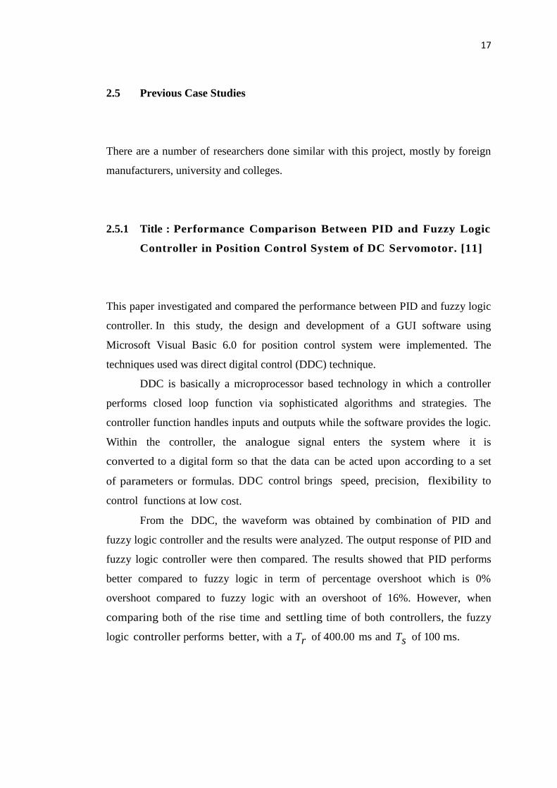
2.5.1 Title : Performance Comparison Between PID and Fuzzy Logic
Controller in Position Control System of DC Servomotor. [11]
This paper investigated and compared the performance between PID and fuzzy logic
controller. In this study, the design and development of a GUI software using
Microsoft Visual Basic 6.0 for position control system were implemented. The
techniques used was direct digital control (DDC) technique.
DDC is basically a microprocessor based technology in which a controller
performs closed loop function via sophisticated algorithms and strategies. The
controller function handles inputs and outputs while the software provides the logic.
Within the controller, the analogue signal enters the system where it is
converted to a digital form so that the data can be acted upon according to a set
of parameters or formulas. DDC control brings speed, precision, flexibility to
control functions at low cost.
From the DDC, the waveform was obtained by combination of PID and
fuzzy logic controller and the results were analyzed. The output response of PID and
fuzzy logic controller were then compared. The results showed that PID performs
better compared to fuzzy logic in term of percentage overshoot which is 0%
overshoot compared to fuzzy logic with an overshoot of 16%. However, when
comparing both of the rise time and settling time of both controllers, the fuzzy
logic controller performs better, with a Tr of 400.00 ms and Ts of 100 ms.

18
2.5.2 Title : Controller design for servo motor using MATLAB. [12]
In this paper, the controller for servo motor was designed using MATLAB software
by simulink model block diagram. Some ideas to create block diagram is shown in
this report based on their project. The comparison between three case studies was
discussed in this paper. Simulations are performed for three different values of the
armature resistance in order to investigate effect of armature current [12]. To make
an expression controller design, this article is generating the design by using
MATLAB/SIMULINK. This new design method gives us a simple way to design a
speed controller for a servo motor and design in discrete time systems. The
experimental is used to obtain the transfer function to design PID controller [12].
This reference is denoting how to design the PID controller. A PID feedback loop
can maintain the system stability because it can eliminate the error, reduce the
overshoot and reduce the settling time. The basic concept of PID control can be
generalized within the same structure PID controller design method was proposed to
deal with both performance and robust stability specifications for multivariable
processes in order to give the best performance for servo motor controller in the
future [12].
2.5.3 Title : PID Controller Design For Controlling DC Motor Speed Using
MATLAB Application. [13]
This project was about the development of a PID controller design for DC motor
using MATLAB. IN this project, firstly, a PID controller was designed using
MATLAB/ Simulink software. The mathematical mode of Dc motor was then
developed using Ziegler-Nichols method and trial and error method. Next, the control
algorithm was built in the Matlab/ Simulink software and compiled with Real-Time
Window Target. The Real-Time Window Target Toolbox includes an analog input
and analog output that provide connection between the data acquisition card (PCI-

19
1710HG) and the simulink model. The system used Litton - Clifton Precision Servo
DC Motor JDH-2250.
2.5.4 Title : DC Motor speed and position control using analog PID controller.
[14]
This paper presented the real time DC motor speed and position control in order to
know the function of PID controller as an operational amplifier. DC motor control
has been used for variable speed and position applications for many decades and
historically were the first choices for speed control applications requiring accurate
speed control, controllable torque, reliability and simplicity. The PID controller was
designed by using MATLAB/ Simulink to obtain the best coefficients that could
achieve the performance requirement of the DC motor. Then, the estimated
parameters was transfered to the hardware part that executed the PID controller. The
graphical user interfaces (GUI) was developed using Microsoft Visual Basic 6.0 to
plot and monitor the system response in real time [13]. Based on the concept that
showed in this paper, the output from the control system could be connected with
personal computer through DAQ that showed the response of the system. In this part,
analog signal from plant was converted to digital signal and transfer to personal
computer to plot and analyze the response during operation. During the experiment,
the PID controller corrected the error by calculating and analyzing it that resulted in
increasing transient response between the command and actual movement.
2.5.5 Title : Real –Time DC Servo Motor Position Control by PID Controllers
Using Labview. [15]
This paper was about the design of a position control of a DC servo motor using PID
Control algorithms. The controller was designed based on Labview program and the
real - time position control of the DC servo motor was realized by using DAQ

20
device. All the codes were developed in the Labview Real-Time Development
System and then downloaded the real-time code to run embedded applications on a
PXI. The servo systems are generally controlled by conventional Proportional
Integral Derivative (PID) controllers. This system aimed to achieve some of the
criteria when applied PID controller such as less steady state error, minimum settling
time, minimum rising time and less overshoot at the system. To achieve the aims,
the authors adjusted the PID controller parameters by using some other tuning
techniques. The system provided output position in real time in order to obtain
system responses of PID controller.
2.6 Conclusion
All the references for this project’s literature review have helped the author to focus
on preparation of the project and generate ideas to execute this project successfully.
The PID controllers used by those papers prove that they are efficient in controlling a
DC motor.

21
CHAPTER 3
METHODOLOGY
In this chapter, method and alternatives that have been used for designing the
controller are discussed and explained in detail, including steps for getting the state-
space model of the Dc motor, PID design, hardware configuration and the
implementation of PID controller on microcontroller, PIC.
3.1 System Overview
Proportional -Integral-Derivative (PID) controller design for servo motor consists of
two main parts in designing mathematical model for controller (PID) and servo
motor. In this project, PID controller is designed using MATLAB software then
compared with the designed system generated. This PID controller can compare the
results by using simulation and hardware result.

22
3.2 Flowchart of PID Controller Design For Dc Servo Motor.
Figure 3.1 shows the flowchart used as a guideline in completing the project.
Figure 3.1: Sequences of PID Controller Implementation on the DC
Servomotor
Mathematical Model of Controller (PID)
Design Block Diagram
Implement the Design in MATLAB
Simulation and Analysis
Find the best value
of PID
Output and Result
ERROR?
END
YES
YES
NO
NO
Interface with hardware
Simulation and Analysis
ERROR?

23
Figure 3.2 illustrates the flowchart to implement the PID controller.
Figure 3.2: The PID controller design for position control project methodology.
Start
General Literature Review
Research on the Potential of Digital Servo Motor Control
Available
Modeling of Digital Servo Motor Control
Design PID Controller
Debug and Troubleshooting
Use MPLAB X IDE for the Software
Development
Error
Thesis Writing
End
Yes
No
No
Yes
Test performance of PID Controller

24
3.3 Methods and Approach
3.3.1 Digital Servo Motor Control
The hardware of the servo system consists of the mechanical unit containing the Dc
brush-type servo motor, motor shaft encoder, rail encoder, platform, belt drives and
pulleys for moving the platform, flywheel and friction brake.
The digital servo system uses a brush-type permanent-magnet dc motor. As
with conventional Dc motors that employ a field winding, permanent-magnet Dc
motors create mechanical energy by the interaction between the magnetic field
created by current flowing through the armature windings and the magnetic field
created by the permanent magnet [8].
The interaction between these two magnetic fields produces a force (called
the torque) that causes the rotor/armature to rotate. The connections to the armature
windings are made through brushes, which commutate or switch the current to the
armature winding loops in order to produce a torque that causes the rotor/armature
assembly to rotate continuously. Reversing the polarity of the dc power supply to the
armature results in a current flow to the armature windings that produces a torque
causing the rotor/armature to rotate in the opposite direction.
3.3.2 Servo Motor Modeling
Servo motor is used for position or speed control in closed loop control systems. The
equivalent circuit diagram of servo motor is presented in Figure 3.3. The armature is
modelled as a circuit with resistance, Ra connected in series with an inductance, La
and a voltage source, Vb(t) representing the back emf in the armature when the rotor
rotates.

53
REFERENCES
1. Ming- Yuan Shieh and Tzuu-Hseng S. Li (2009), Implementation of
Integrated Fuzzy Logic Controller for Servomotor System, Dept. of Electrical
Engineering National Cheng Kung University, Tainan. Taiwan, Republic of
China
2. C.-C. Kung and K.-H. Su (2005), Adaptive fuzzy position control for
electrical servodrive via total-sliding-mode technique, IEEE Proc.-Electr
Power Appl., Vol.152, 6.
3. Jin Z., Shuyun W. and Jinbang X (2004), Improving method fuzzy control
AC speed drive, IEEE Proceedings of the 5th
World Congress on Intelligent
Control and Automation, pp. 4500-4503.
4. Li-Xin Wang (1999), Analysis and design of hierarchical fuzzy system, IEE
Tans. On Fuzzy systems. vol. 7, no.5, 617-624.
5. A. Wu and P. K. S. Tam (2000), A fuzzy neural network based on fuzzy
hierarchy error approach, IEEE Trans. Fuzzy Syst., vol. 8, pp. 808–816.
6. Shimojima. Koji, Torhio FukvdB and Yasuhisa Haxgawa (1995), Self-
running fuzzy model with adaptive membership function, rules, and
hierarchical structure based on genetic algorithm, Fuzzy sets and systems, vol.
71, pp. 295-309. hierarchy error approach, IEEE Trans. Fuzzy Syst., vol. 8,
pp. 808–816.
7. Alia J. Mohammed (2012), Speed Control of Separately Excited DC Motor
Driver (SEDM) Based on Adaptive Neuro-Fuzzy Logic Controller, Eng.
&Tech. Journal, Vol.31, No.2, 2013

54
8. M.A. Ahmad, R.M.T. Raja Ismail, M.S. Ramli (2010), Control Strategy of
Buck Converter Driven Dc Motor: a Comparative Assessment, Universiti
Malaysia Pahang.
9. K. Astrom and T. Hugglund(1995), PID Controllers: Theory, Design and
Tuning, 2nd edition ISBN 1-55617-516-7
10. Lab-Volt Ltd.,Digital Servo Motor Control,1st Edition,Canada,2010.ISBN
978-2-89640-391-2.
11. Mohd Fua'ad Rahmat and Mariam Md Ghazaly (2006), Performance
Comparison Between PID and Fuzzy Logic Controller in Position
Control System of DC Servomotor, Jurnal Teknologi, 45(D) Dis. 2006:
1–17
12. Vikas Kumawat and Rajeev Gupta (2008), Controller design for servo motor
using MATLAB, Control & Instrument Department, IEEE, 2008
13. Mohamed Farid Bin Mohamed Faruq,(2008), PID Controller Design for
Controller DC Motor Speed Using MATLAB Application, Universiti
Malaysia Pahang.
14. Ahmad Ismail, Man (2008) DC Motor Speed And Position Control Using
Analog PID Controller. Project Report. UTeM, Melaka, Malaysia.
15. Jianying Liu, Pengju Zhang, Fei Wang (2009), Real –Time DC Servo Motor
Position Control by PID Controllers Using Labview, Department of
Electrical Engineering, China.
16. Charles L.Phillips, H. Troy Nagle, (1995), Digital Control System Analysis
And Design, 3rd
edition, Prentice Hall,Inc. A Person Education Company.
Upper Saddle River, New Jersey 07458.
17. Katsuhiko Ogata,(1995),Discrete Time Control System, 2nd
edition, Prentice
Hall,Upper Saddle River,New Jersey 07458
18. Dingyu Xue, YangQuan Chen, and Derek P. Atherton, "Linear Feedback
Control: Analysis and Design with MATLAB", the Society for Industrial and
Applied Mathematics, Philadelphia, ISBN 978-0- 898716-38-2, 2007.