Embed Size (px)
Citation preview
BIFFI ICON 2000INSTRUCTION AND OPERATING MANUAL
www.biffi.it Copyright © Biffi. All rights reserved. VCIOM-01232-EN 19/01
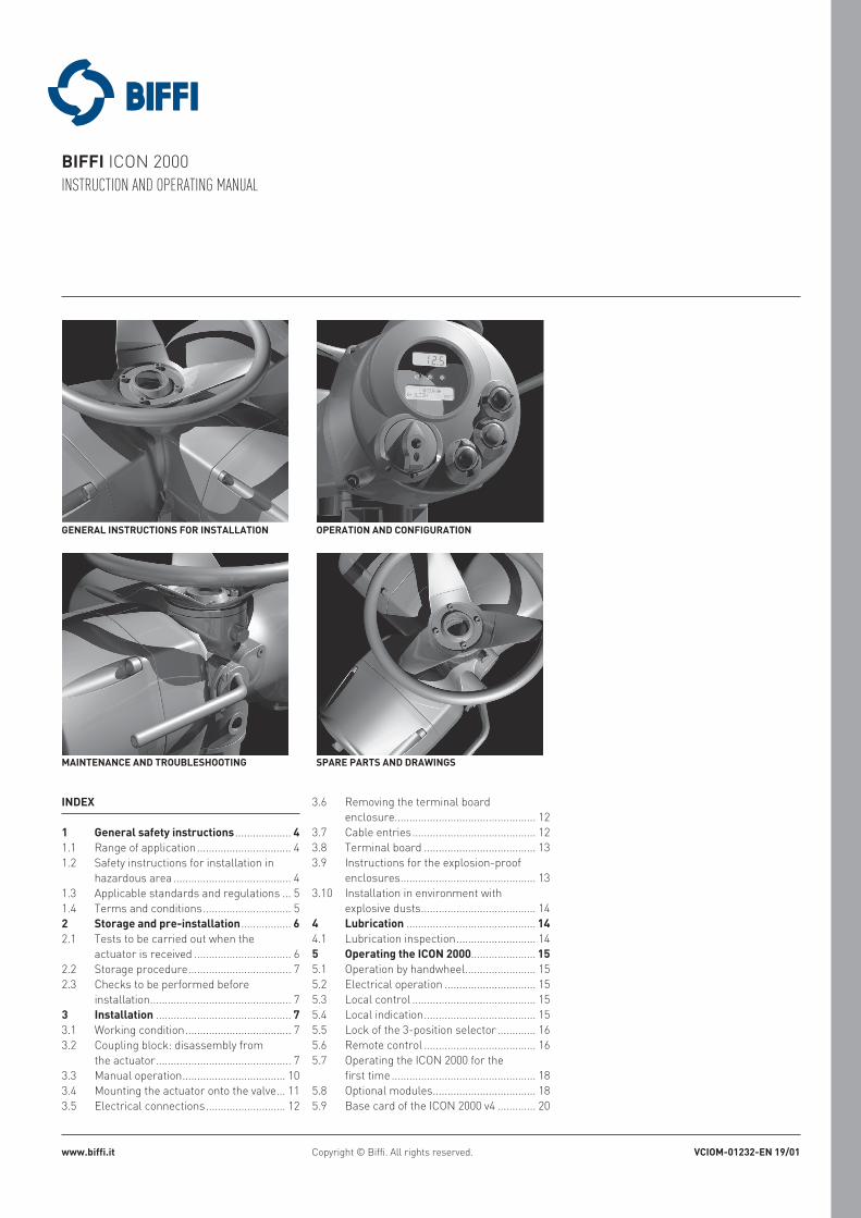
GENERAL INSTRUCTIONS FOR INSTALLATION OPERATION AND CONFIGURATION
MAINTENANCE AND TROUBLESHOOTING SPARE PARTS AND DRAWINGS
INDEX
1 General safety instructions ................... 41.1 Range of application ................................ 41.2 Safety instructions for installation in
hazardous area ........................................ 41.3 Applicable standards and regulations ... 51.4 Terms and conditions .............................. 52 Storage and pre-installation ................. 62.1 Tests to be carried out when the
actuator is received ................................. 62.2 Storage procedure ................................... 72.3 Checks to be performed before
installation ................................................ 73 Installation .............................................. 73.1 Working condition .................................... 73.2 Coupling block: disassembly from
the actuator .............................................. 73.3 Manual operation ................................... 103.4 Mounting the actuator onto the valve ... 113.5 Electrical connections ........................... 12
3.6 Removing the terminal board enclosure................................................ 12
3.7 Cable entries .......................................... 123.8 Terminal board ...................................... 133.9 Instructions for the explosion-proof
enclosures .............................................. 133.10 Installation in environment with
explosive dusts ....................................... 144 Lubrication ............................................ 144.1 Lubrication inspection ........................... 145 Operating the ICON 2000...................... 155.1 Operation by handwheel ........................ 155.2 Electrical operation ............................... 155.3 Local control .......................................... 155.4 Local indication ...................................... 155.5 Lock of the 3-position selector ............. 165.6 Remote control ...................................... 165.7 Operating the ICON 2000 for the
first time ................................................. 185.8 Optional modules ................................... 185.9 Base card of the ICON 2000 v4 ............. 20
2
Addendum A c Ex de IIB+H2 T4 Gb / c Ex tb IIIC T135°C Db IP66/68 c Ex de ia IIB+H2 T4 Gb / c Ex tb IIIC T135°C Db IP66/6814 Safety instructions ............................... 6114.1 General ................................................... 6114.2 Identification of main parts ................... 61
Addendum B c Ex de IIB+H2 T4 Gb / c Ex tb IIIC T135°C Db IP66/68 c Ex de ia IIB+H2 T4 Gb / c Ex tb IIIC T135°C Db IP66/6822 Safety instructions ............................... 6622.1 General ................................................... 6622.2 Identification of main parts ................... 6623 Check for right application .................. 6723.1 Marking .................................................. 6724 Applicable general standards
and regulations ..................................... 6725 Terms and conditions ........................... 6726 Manufacturer’s liability ....................... 6727 Storage and pre-installation ............... 6827.1 Storage procedure ................................. 6827.2 Checks to be performed before
installation .............................................. 6828 Installation ............................................ 6828.1 Working condition .................................. 6828.2 Identification of entry ............................. 6828.3 Wiring ..................................................... 6928.4 Cable connection ................................... 6928.5 Installation in ambient with
explosive dusts ....................................... 6929 Maintenance .......................................... 7029.1 Periodic inspections .............................. 7029.2 Dismantling and reassembling ............ 7029.3 Repairs ................................................... 70
BIFFI ICON 2000INSTRUCTION AND OPERATING MANUAL
6 Local controls........................................ 216.1 Description of the local operator
interface ................................................. 216.2 Configuration options ............................ 246.3 Entering the view mode ......................... 256.4 Entering the set-up mode ..................... 256.5 Exit from view and set-up modes ......... 257 Set-up menu .......................................... 278 View menu ............................................. 299 Set-up routines ..................................... 319.1 Actuator set-up ...................................... 319.2 Valve data ............................................... 399.3 Maintenance ........................................... 409.4 Example of set-up routine .................... 4210 View routines ........................................ 4310.1 Actuator set-up ...................................... 4310.2 Name plate ............................................. 4310.3 Valve data ............................................... 4310.4 Maintenance ........................................... 4310.5 Example of view routine ........................ 4811 Maintenance .......................................... 4911.1 Standard maintenance .......................... 4911.2 Special maintenance ............................. 4911.3 Lithium battery change ......................... 50
15 Check for right application .................. 6215.1 Marking .................................................. 6216 Applicable general standards
and regulations ..................................... 6217 Terms and conditions ........................... 6218 Manufacturer’s liability ....................... 6219 Storage and pre-installation ............... 6319.1 Storage procedure ................................. 6319.2 Checks to be performed before
installation .............................................. 6320 Installation ............................................ 6320.1 Working condition .................................. 6320.2 Identification of entry ............................. 6320.3 Wiring ..................................................... 6420.4 Cable connection ................................... 6420.5 Installation in ambient with
explosive dusts ....................................... 6421 Maintenance .......................................... 6521.1 Periodic inspections .............................. 6521.2 Dismantling and reassembling ............ 6521.3 Repairs ................................................... 65
12 Troubleshooting ................................... 5112.1 The electronics do not switch on
when powered ........................................ 5112.2 DC output voltage not available at
the terminals .......................................... 5112.3 The actuator does not work from
remote controls ..................................... 5112.4 The motor is very hot and does
not start .................................................. 5112.5 The motor runs but the actuator
does not move the valve ........................ 5212.6 The manual override can’t be
engaged .................................................. 5212.7 The valve does not seat correctly ......... 5212.8 Excessive torque for valve operation .... 5212.9 The actuator does not stop in fully
open or fully closed position ................. 5212.10 The numeric position display
indicates “E01” ....................................... 5212.11 Diagnostic messages ............................ 5313 Parts list and drawings ........................ 5513.1 Introduction ............................................ 55
3
BIFFI ICON 2000INSTRUCTION AND OPERATING MANUAL
Addendum C c Ex de IIB+H2 T4 Gb / c Ex tb IIIC T135°C Db IP66/68 c Ex de ia IIB+H2 T4 Gb / c Ex tb IIIC T135°C Db IP66/6830 Safety instructions ............................... 7131 Instructions for right installation ....... 7131.1 Marking .................................................. 7132 Applicable directives, general
standards and norms ........................... 7233 Terms and conditions ........................... 7234 Manufacturer’s liability ....................... 7235 Storage and pre-installation ............... 7235.1 Storage procedure ................................. 7235.2 Checks to be performed before
installation .............................................. 7236 Installation ............................................ 7336.1 Working condition .................................. 7336.2 Identification of entries .......................... 7336.3 Electrical connections ........................... 7336.4 Cable connection ................................... 7336.5 Installation in ambient with
explosive dusts ....................................... 7337 Maintenance .......................................... 7437.1 Periodic inspections .............................. 7437.2 Dismantling and reassembling ............ 7437.3 Repairs ................................................... 74
Addendum D c Ex de IIB+H2 T4 Gb / c Ex tb IIIC T135°C Db IP66/68 c Ex de ia IIB+H2 T4 Gb / c Ex tb IIIC T135°C Db IP66/6838 Safety instructions ............................... 7539 Instructions for right installation ....... 7539.1 Marking .................................................. 7540 Applicable directives, general
standards and norms ........................... 7641 Terms and conditions ........................... 7642 Manufacturer’s liability ....................... 7643 Storage and pre-installation ............... 7643.1 Storage procedure ................................. 7643.2 Checks to be performed before
installation .............................................. 7644 Installation ............................................ 7744.1 Working condition .................................. 7744.2 Identification of entries .......................... 7744.3 Electrical connections ........................... 7744.4 Cable connection ................................... 7744.5 Installation in ambient with
explosive dusts ....................................... 7745 Maintenance .......................................... 7845.1 Periodic inspections .............................. 7845.2 Dismantling and reassembling ............ 7845.3 Repairs ................................................... 78
Addendum E c Ex de IIB+H2 T4 Gb / c Ex tb IIIC T135°C Db IP66/68 c Ex de ia IIB+H2 T4 Gb / c Ex tb IIIC T135°C Db IP66/6846 Safety instructions ............................... 7947 Instructions for right installation ....... 7947.1 Marking .................................................. 7948 Applicable directives, general
standards and norms ........................... 8049 Terms and conditions ........................... 8050 Manufacturer’s liability ....................... 8051 Storage and pre-installation ............... 8051.1 Storage procedure ................................. 8051.2 Checks to be performed before
installation .............................................. 8052 Installation ............................................ 8152.1 Working condition .................................. 8152.2 Identification of entries .......................... 8152.3 Electrical connections ........................... 8152.4 Cable connection ................................... 8152.5 Installation in ambient with
explosive dusts ....................................... 8153 Maintenance .......................................... 8253.1 Periodic inspections .............................. 8253.2 Dismantling and reassembling ............ 8253.3 Repairs ................................................... 82
4
WARNINGIt is assumed that the installation, setting, commissioning, maintenance and repair works are carried out by qualified personnel and checked by responsible specialists.
1 GENERAL SAFETY INSTRUCTIONS
1.1 RANGE OF APPLICATION
ICON 2000 electric actuators covered in this I&O Manual are designed for the operation of any kind of industrial valves used in heavy industrial, chemical, petrochemical plants. Biffi will not be liable for any possible damage resulting from use in other than the designated applications. Such risk lies entirely with the user.
The noise emitted by the electric actuator in normal working conditions is less than 66 dB (A) with peak value 115 dB (C). Standard reference ISO 11202 (1st ed., 1995-12-15).
The electric actuators are designed in accordance with the applicable international rules and specifications but the following regulations must be observed in any case:- The general installation and safety
regulations.- The plant specific regulations and
requirements.- The proper use of personal protective devices
(glasses, clothing, gloves).- The proper use of tools, lifting and transport
equipment.
1.2 SAFETY INSTRUCTIONS FOR INSTALLATION IN HAZARDOUS AREA
WARNINGIn case the electric actuator must be installed in an HAZARDOUS AREA, as defined by the local rules, it is mandatory to check if the nameplate of the electric actuator specifies the appropriate degree of protection. Maintenance and repair works must be carried out by qualified personnel and checked by responsible specialists.
ICONs are designed according to IEC/EN 60079-0, IEC/EN 60079-1, IEC/EN 50079-31 standards. Different types of protection are available, depending on the marking printed on the actuator label: Ex d IIB Txx, Ex d IIC Txx with “Explosion proof” terminal board enclosure, or Ex d e IIB Txx, Ex d e IIB+H2 Txx, Ex d e IIC Txx with “Increased safety” terminal board enclosure. They are suitable in hazardous area classified against the risk of explosion for the presence of gas and dust.Actuators have IP66/68 degree of protection according to EN 60529.
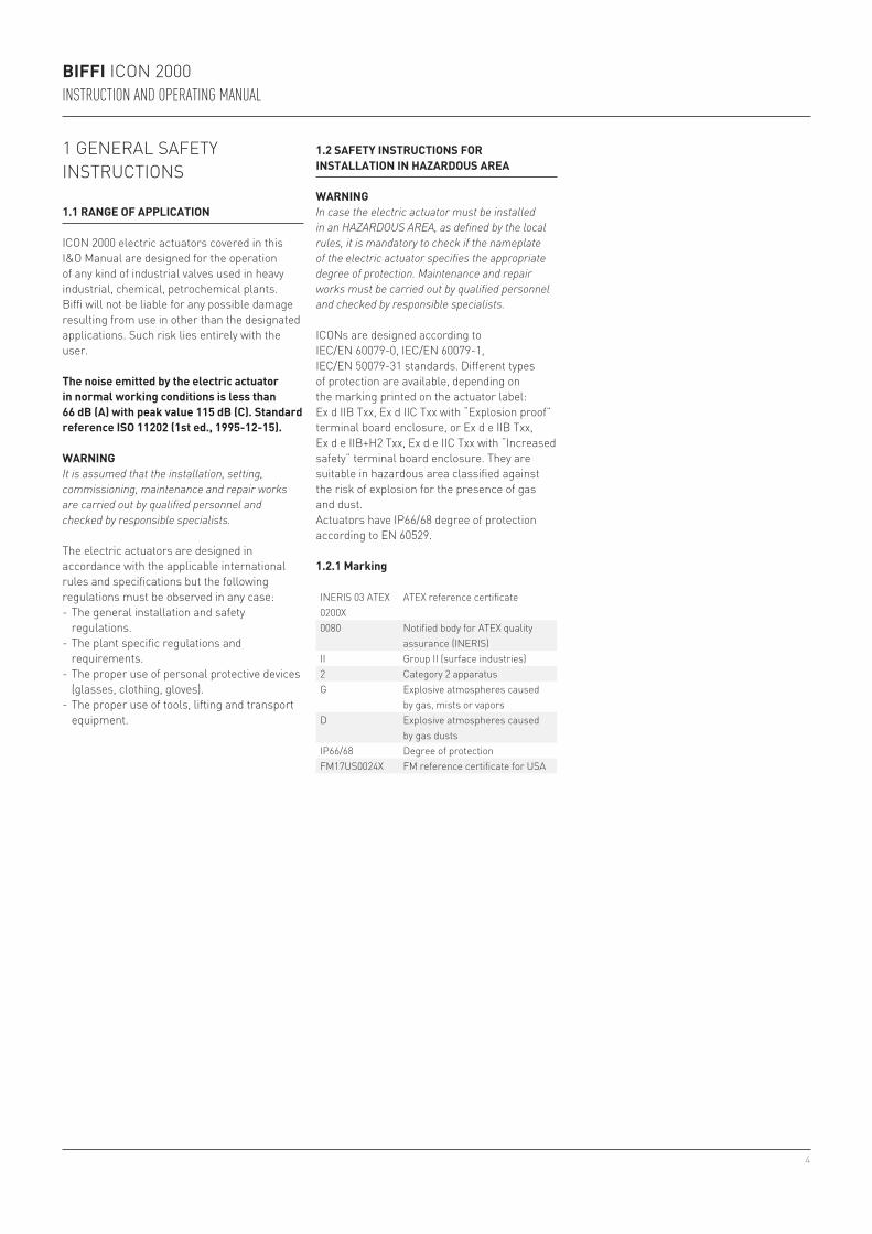
1.2.1 Marking
INERIS 03 ATEX 0200X
ATEX reference certificate
0080 Notified body for ATEX quality assurance (INERIS)
II Group II (surface industries)2 Category 2 apparatusG Explosive atmospheres caused
by gas, mists or vaporsD Explosive atmospheres caused
by gas dustsIP66/68 Degree of protectionFM17US0024X FM reference certificate for USA
BIFFI ICON 2000INSTRUCTION AND OPERATING MANUAL
5
BIFFI ICON 2000INSTRUCTION AND OPERATING MANUAL
1.3 APPLICABLE STANDARDS AND REGULATIONS
1.4 TERMS AND CONDITIONS
Biffi guarantees each single product to be free from defects and to conform to current goods specifications. The warranty period is one year from the date of installation by the first user, or eighteen months from the date of shipment to the first user, whichever occurs first. No warranty is given for products or components manufactured by third-party companies, or for goods which have been subject to misuse, improper installation, corrosion, or which have been modified or repaired by unauthorized personnel. Repair work due to improper use will be charged at standard rates.
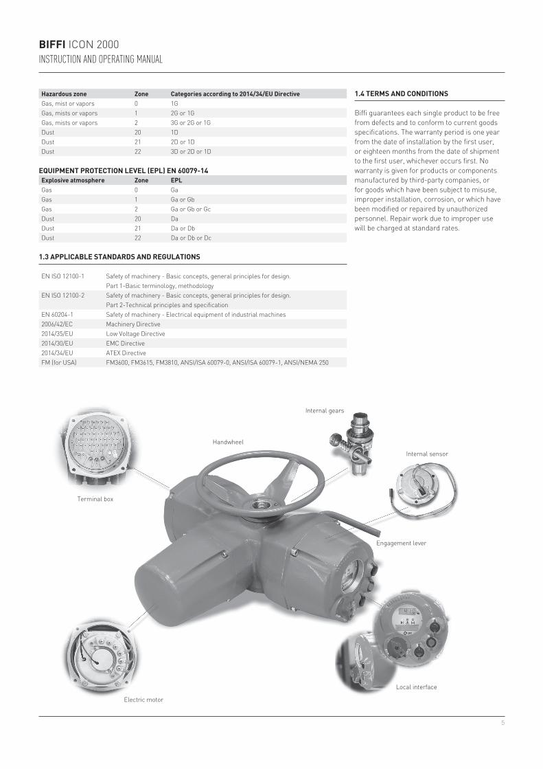
Terminal box
Electric motor
Local interface
Engagement lever
Internal sensor
Internal gears
Handwheel
EQUIPMENT PROTECTION LEVEL (EPL) EN 60079-14Explosive atmosphere Zone EPLGas 0 GaGas 1 Ga or GbGas 2 Ga or Gb or GcDust 20 DaDust 21 Da or DbDust 22 Da or Db or Dc
Hazardous zone Zone Categories according to 2014/34/EU DirectiveGas, mist or vapors 0 1GGas, mists or vapors 1 2G or 1GGas, mists or vapors 2 3G or 2G or 1GDust 20 1DDust 21 2D or 1DDust 22 3D or 2D or 1D
EN ISO 12100-1 Safety of machinery - Basic concepts, general principles for design. Part 1-Basic terminology, methodology
EN ISO 12100-2 Safety of machinery - Basic concepts, general principles for design. Part 2-Technical principles and specification
EN 60204-1 Safety of machinery - Electrical equipment of industrial machines2006/42/EC Machinery Directive2014/35/EU Low Voltage Directive2014/30/EU EMC Directive2014/34/EU ATEX DirectiveFM (for USA) FM3600, FM3615, FM3810, ANSI/ISA 60079-0, ANSI/ISA 60079-1, ANSI/NEMA 250
6
BIFFI ICON 2000INSTRUCTION AND OPERATING MANUAL
2 STORAGE AND PRE-INSTALLATION
2.1 TESTS TO BE CARRIED OUT WHEN THE ACTUATOR IS RECEIVED
If the actuator is received already mounted on the valve, all operations should have already been performed during valve/actuator assembly.• Check that the display is active.• Turn the handwheel until the valve is in a
completely open position.• Check that the display reads 100% indicating
that the valve is completely open.• Rotate the handwheel clockwise and bring
the valve to a completely closed position.• Check that the display reads 0% indicating
that the valve is completely closed.If the test result is satisfactory, the actuator has already been adjusted and you can proceed with the electrical connection.If the actuator is delivered separately from the valve, or the above procedure shows that the position is incorrect, all operations described in this manual must be carried out.• Check that no damage has occurred during
transport, especially to the push-buttons, the display area glass and the selector.
• Check the information on the nameplate: serial number and performance data (nominal torque, operation speed, protection class, motor supply voltage, etc.), and verify the corresponding data on the display (see chapter 10, View routines).
Make sure all accessories have been received with the shipment, as described in the delivery documentation.
2.2 STORAGE PROCEDURE
IMPORTANTNot performing the following procedures will invalidate the product guarantee.
2.2.1 GeneralThe actuator leaves the factory in perfect condition, as guaranteed by an individual test certificate. In order to maintain these characteristics until the actuator is installed on site, proper procedures must be taken for preservation during the storage period.Biffi actuators are weatherproof to IP66/68. This condition can only be maintained if the units are correctly installed/connected on site and if they have been correctly stored.The standard plastic plugs used to close the cable entries are not weatherproof, they just prevent the entry of undesired objects during transport.
2.2.2 Storage for a brief period (less than one year)
2.2.2.1 Indoor storage• Make sure that the actuators are kept in a dry
place, laid on a wooden pallet and protected from dust.
2.2.2.2 Outdoor storage• Make sure that the actuators are protected
from the direct action of weather agents (protection by a canvas tarp or similar cover).
• Place the actuators on a wooden pallet, or some other raised platform, so that they are not in direct contact with the ground.
• If the actuators are supplied with standard plastic plugs, remove them from the cable entries and replace them with weatherproof plugs.
2.2.3 Long period storage (more than one year)
2.2.3.1 Indoor storage(In addition to the instructions at paragraph 2.2.2.1)• If the actuators are supplied with standard
plastic plugs, replace them with weatherproof plugs.
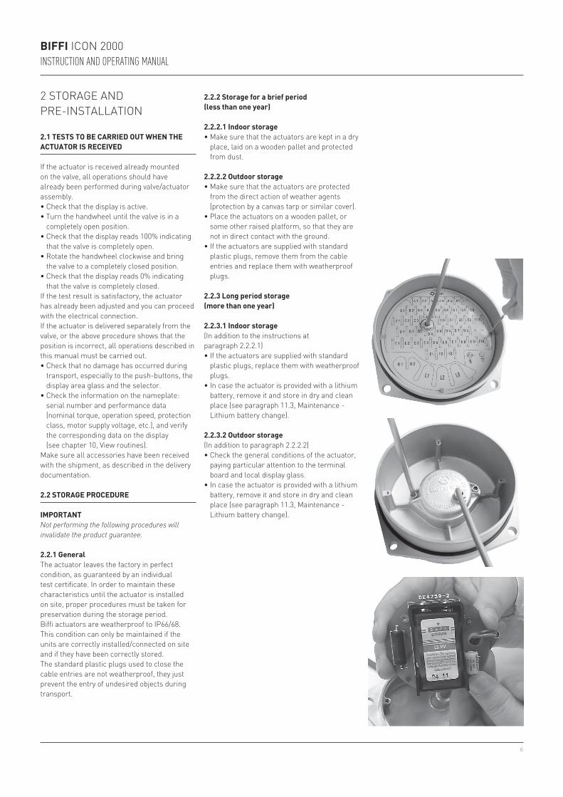
• In case the actuator is provided with a lithium battery, remove it and store in dry and clean place (see paragraph 11.3, Maintenance - Lithium battery change).
2.2.3.2 Outdoor storage(In addition to paragraph 2.2.2.2)• Check the general conditions of the actuator,
paying particular attention to the terminal board and local display glass.
• In case the actuator is provided with a lithium battery, remove it and store in dry and clean place (see paragraph 11.3, Maintenance - Lithium battery change).
7
BIFFI ICON 2000INSTRUCTION AND OPERATING MANUAL
2.3 CHECKS TO BE PERFORMED BEFORE INSTALLATION
• Make sure the valve to be motorized is the appropriate one for coupling to the actuator.
• The electrical supply cables must be suitable for the power rating (see the test certificate that comes with the actuator).
• Gather the right tools for the assembly and for setting the actuator controls.
If a long storage period has occurred, before reinstalling the actuator, please:• Check the status of the O-ring seals.• Check the installation of the plugs or cable
glands on the cable entries.• Check whether the enclosure covers or the
actuator body are cracked or broken.• Check the oil level in the actuator and top up
if necessary.• Put the batteries back into place
(see paragraph 11.3, Maintenance - Lithium battery change).
3 INSTALLATION
3.1 WORKING CONDITION
The standard actuators are suitable for the following environment temperatures: -30°C +85°C (-22°F to +185°F)Special versions are available for extreme environment temperatures: -40°C +70°C (-40°F to +158°F) -55°C +70°C (-67°F to +158°F)Note: only for Ex d or Ex d e versions, for ambient temperature range, see the specific attached addendum.
IMPORTANTCheck the "temperature environment range" embossed on the nameplate, for the correct utilisation with respect to the environment temperature.
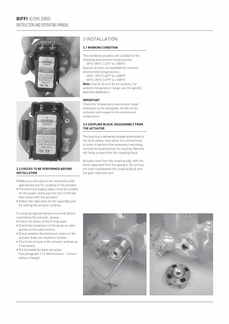
3.2 COUPLING BLOCK: DISASSEMBLY FROM THE ACTUATOR
The bushing is delivered already assembled to the drive sleeve, even when it is unmachined. In order to perform the necessary machining, remove the bushing from its housing. Remove the fixing screws from the coupling block.
Actuator view from the coupling side, with the block separated from the gearbox. Do not lose the seal ring between the coupling block and the gear reduction unit.
8
BIFFI ICON 2000INSTRUCTION AND OPERATING MANUAL
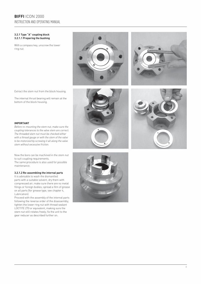
3.2.1 Type “A” coupling block3.2.1.1 Preparing the bushing
With a compass key, unscrew the lower ring nut.
Extract the stem nut from the block housing.
The internal thrust bearing will remain at the bottom of the block housing.
IMPORTANTBefore re-mounting the stem nut, make sure the coupling tolerances to the valve stem are correct. The threaded stem nut must be checked either with a thread gauge or with the stem of the valve to be motorized by screwing it all along the valve stem without excessive friction.
Now the bore can be machined in the stem nut to suit coupling requirements.The same procedure is also used for possible maintenance.
3.2.1.2 Re-assembling the internal partsIt is advisable to wash the dismantled parts with a suitable solvent; dry them with compressed air; make sure there are no metal filings or foreign bodies; spread a film of grease on all parts (for grease type, see chapter 4, Lubrication).Proceed with the assembly of the internal parts following the reverse order of the disassembly; tighten the lower ring nut with thread sealant LOCTITE 270 or equivalent, making sure the stem nut still rotates freely; fix the unit to the gear reducer as described further on.
9
BIFFI ICON 2000INSTRUCTION AND OPERATING MANUAL
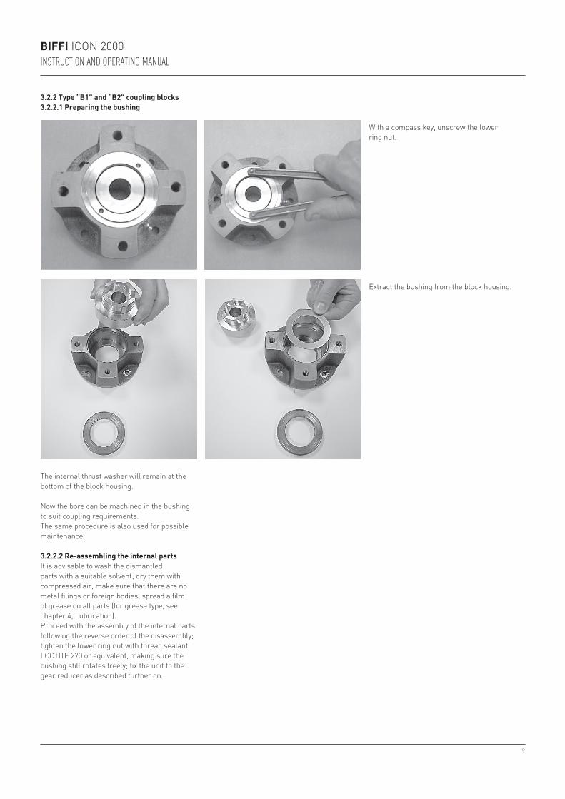
With a compass key, unscrew the lower ring nut.
Extract the bushing from the block housing.
The internal thrust washer will remain at the bottom of the block housing.
Now the bore can be machined in the bushing to suit coupling requirements.The same procedure is also used for possible maintenance.
3.2.2.2 Re-assembling the internal partsIt is advisable to wash the dismantled parts with a suitable solvent; dry them with compressed air; make sure that there are no metal filings or foreign bodies; spread a film of grease on all parts (for grease type, see chapter 4, Lubrication).Proceed with the assembly of the internal parts following the reverse order of the disassembly; tighten the lower ring nut with thread sealant LOCTITE 270 or equivalent, making sure the bushing still rotates freely; fix the unit to the gear reducer as described further on.
3.2.2 Type “B1” and “B2” coupling blocks3.2.2.1 Preparing the bushing
10
TO CLOSE
BIFFI ICON 2000INSTRUCTION AND OPERATING MANUAL
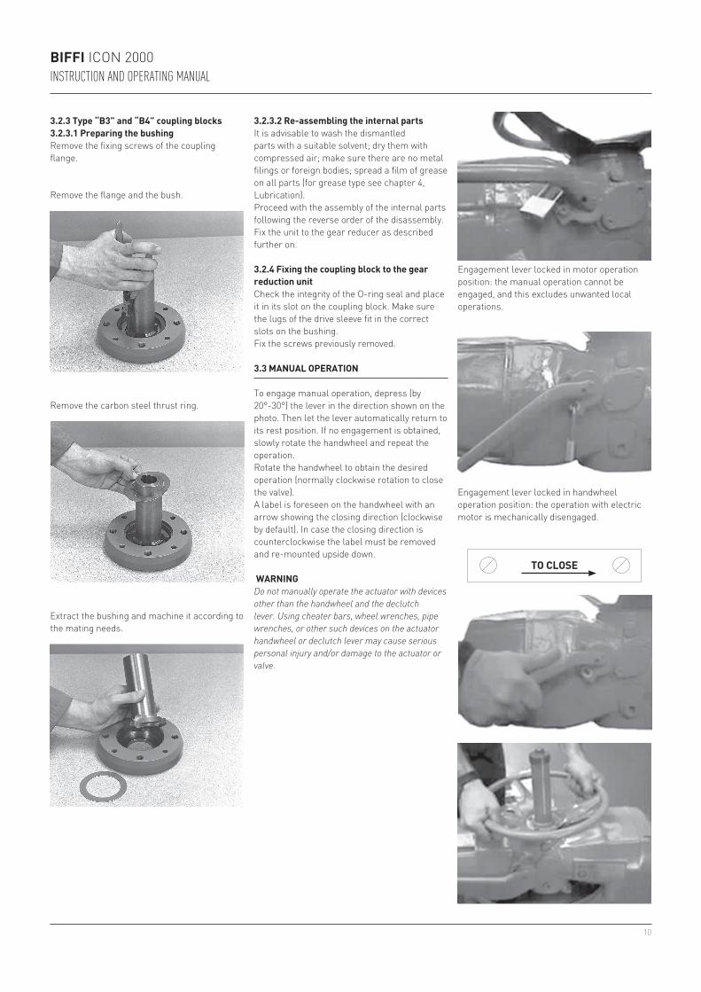
3.2.3 Type “B3” and “B4” coupling blocks3.2.3.1 Preparing the bushingRemove the fixing screws of the coupling flange.
Engagement lever locked in motor operation position: the manual operation cannot be engaged, and this excludes unwanted local operations.
Engagement lever locked in handwheel operation position: the operation with electric motor is mechanically disengaged.
3.3 MANUAL OPERATION
To engage manual operation, depress (by 20°-30°) the lever in the direction shown on the photo. Then let the lever automatically return to its rest position. If no engagement is obtained, slowly rotate the handwheel and repeat the operation.Rotate the handwheel to obtain the desired operation (normally clockwise rotation to close the valve).A label is foreseen on the handwheel with an arrow showing the closing direction (clockwise by default). In case the closing direction is counterclockwise the label must be removed and re-mounted upside down.
WARNINGDo not manually operate the actuator with devices other than the handwheel and the declutch lever. Using cheater bars, wheel wrenches, pipe wrenches, or other such devices on the actuator handwheel or declutch lever may cause serious personal injury and/or damage to the actuator or valve.
3.2.3.2 Re-assembling the internal partsIt is advisable to wash the dismantled parts with a suitable solvent; dry them with compressed air; make sure there are no metal filings or foreign bodies; spread a film of grease on all parts (for grease type see chapter 4, Lubrication).Proceed with the assembly of the internal parts following the reverse order of the disassembly. Fix the unit to the gear reducer as described further on.
3.2.4 Fixing the coupling block to the gear reduction unitCheck the integrity of the O-ring seal and place it in its slot on the coupling block. Make sure the lugs of the drive sleeve fit in the correct slots on the bushing.Fix the screws previously removed.
Remove the carbon steel thrust ring.
Extract the bushing and machine it according to the mating needs.
Remove the flange and the bush.
11
010 32020 38030 46040 56050 73
010 40020 150030 150040 300050 150
BIFFI ICON 2000INSTRUCTION AND OPERATING MANUAL
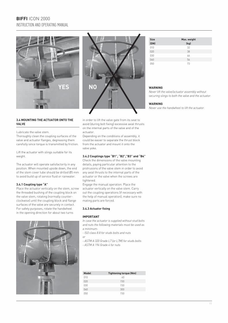
3.4 MOUNTING THE ACTUATOR ONTO THE VALVE
Lubricate the valve stem.Thoroughly clean the coupling surfaces of the valve and actuator flanges, degreasing them carefully since torque is transmitted by friction.
Lift the actuator with slings suitable for its weight.
The actuator will operate satisfactorily in any position. When mounted upside down, the end of the stem cover tube should be drilled Ø5 mm to avoid build up of service fluid or rainwater.
3.4.1 Coupling type “A”Place the actuator vertically on the stem, screw the threaded bushing of the coupling block on the valve stem, rotating (normally counter-clockwise) until the coupling block and flange surfaces of the valve are securely in contact.For safety purposes, rotate the handwheel in the opening direction for about two turns
Size(DN)
Max. weight(kg)
WARNINGNever lift the valve/actuator assembly without securing slings to both the valve and the actuator.
YES NO
WARNINGNever use the handwheel to lift the actuator.
3.4.2 Couplings type “B1”, “B2”,”B3” and “B4”Check the dimensions of the valve mounting details, paying particular attention to the protrusions of the valve stem in order to avoid any axial thrusts to the internal parts of the actuator or the valve when the screws are tightened.Engage the manual operation. Place the actuator vertically on the valve stem. Carry out the coupling operations (if necessary with the help of manual operation); make sure no mating parts are forced.
3.4.3 Actuator fixing
IMPORTANTIn case the actuator is supplied without stud bolts and nuts the following materials must be used as a minimum:- ISO class 8.8 for studs bolts and nutsor- ASTM A 320 Grade L7 (or L7M) for studs bolts- ASTM A 194 Grade 4 for nuts
Model Tightening torque (Nm)
in order to lift the valve gate from its seat to avoid (during bolt fixing) excessive axial thrusts on the internal parts of the valve and of the actuator.Depending on the conditions of assembly, it could be easier to separate the thrust block from the actuator and mount it onto the valve yoke.

12
BIFFI ICON 2000INSTRUCTION AND OPERATING MANUAL
WARNINGDo not damage the mating surface of the cover.
IMPORTANTIn case the screws of the cover must be replaced, a SS AISI 316 must be used with minimum yield strength of 450 N/mm2.
3.5 ELECTRICAL CONNECTIONS
Before powering the actuator check that the supply voltage details on the nameplate are correct for the plant. Access to terminals for electrical connections and commissioning is through the terminal cover, since all settings are non-intrusive. The removal of any other covers without Biffi’s approval will invalidate the warranty.Biffi will not accept any responsibility for any damage or deterioration that may be caused.
IMPORTANTAll the accessories (in particular cable glands) must be certified.As of 30 June 2003, the above accessories must carry the CE certification conforming with 94/9/CE Directive.
3.5.1 Plants requirementsProtection devices (overcurrent breakers, magneto-thermal switches or fuses) should be provided on the plant at Customer care, to protect the mains line in case of motor overcurrent or loss of insulation between phases and earth.
3.6 REMOVING THE TERMINAL BOARD ENCLOSURE
Using a 8 mm Allen key, loosen the four screws and remove the cover.
3.7 CABLE ENTRIES
The sealing of cables and conduit entries should be carried out in accordance with National Standards or the Regulatory Authorities that have certified the actuators. This is particularly true for units that are certified for use in hazardous areas where the method of sealing must be to an approved standard, and cable glands, reducers, plugs and adapters must be approved and separately certified.
Certified cable entries:- Standard Rc ISO7/1 (cable entries 2x1”+1x1½”+ (optional) 1x¾”
+ (optional) 1x1¾”)- Standard ASA/NPT (cable entries 2x1”+1x1½”+ (optional) 1x¾"
+ (optional) 1x1¾")- Metric BS 3643 (cable entries 2xM32+1xM40)- Pg DIN 40430 (cable entries 2xPg21+1xPg29)
Remove the cable entry plugs.
WARNING- The cable reducers are certified according to
the actuator certification.- Refer to the actuator drawing.
IMPORTANT- To prevent any water infiltration through the
line cable conduits, make sure the cable glands have the minimum protection degree required by the plant.
- If rigid conduits are used, we suggest placing a flexible pipe connection between the conduit and the terminal board.
To guarantee weatherproof and explosionproof fit, screw the cable glands tightly (at least 5 turns) and block them with a thread sealant. The use of a thread sealant is necessary in case of explosionproof and weatherproof application.
If some parts of the cable glands have been removed while working on the cable entries put them back into place now to avoid losing the dismantled parts.Unused entries:- For explosionproof construction: unused
entries must be plugged with metal explosionproof plugs and blocked with a thread sealant.
- For weatherproof construction: replace the plastic standard protection plugs supplied with the actuator with metal plugs.
13
BIFFI ICON 2000INSTRUCTION AND OPERATING MANUAL
3.8 TERMINAL BOARD
IMPORTANTThe removal of any other covers without Biffi’s approval will invalidate the warranty. Biffi will not accept any responsibility for any damage or deterioration that may occur as a result of cover removal.
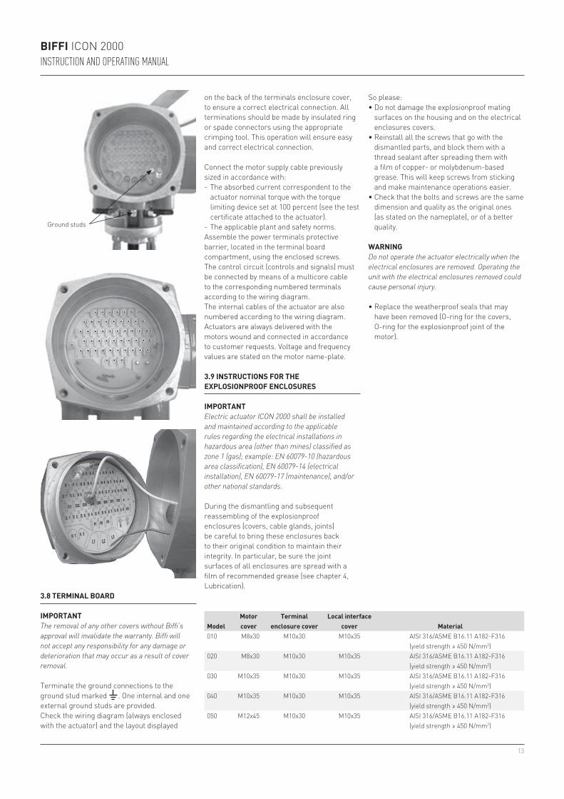
Ground studs
Terminate the ground connections to the ground stud marked . One internal and one external ground studs are provided.Check the wiring diagram (always enclosed with the actuator) and the layout displayed
Connect the motor supply cable previously sized in accordance with:- The absorbed current correspondent to the
actuator nominal torque with the torque limiting device set at 100 percent (see the test certificate attached to the actuator).
- The applicable plant and safety norms.Assemble the power terminals protective barrier, located in the terminal board compartment, using the enclosed screws.The control circuit (controls and signals) must be connected by means of a multicore cable to the corresponding numbered terminals according to the wiring diagram.The internal cables of the actuator are also numbered according to the wiring diagram.Actuators are always delivered with the motors wound and connected in accordance to customer requests. Voltage and frequency values are stated on the motor name-plate.
3.9 INSTRUCTIONS FOR THE EXPLOSIONPROOF ENCLOSURES
IMPORTANTElectric actuator ICON 2000 shall be installed and maintained according to the applicable rules regarding the electrical installations in hazardous area (other than mines) classified as zone 1 (gas); example: EN 60079-10 (hazardous area classification), EN 60079-14 (electrical installation), EN 60079-17 (maintenance), and/or other national standards.
During the dismantling and subsequent reassembling of the explosionproof enclosures (covers, cable glands, joints) be careful to bring these enclosures back to their original condition to maintain their integrity. In particular, be sure the joint surfaces of all enclosures are spread with a film of recommended grease (see chapter 4, Lubrication).
ModelMotor cover
Terminal enclosure cover
Local interface cover Material
010 M8x30 M10x30 M10x35 AISI 316/ASME B16.11 A182-F316 (yield strength ≥ 450 N/mm2)
020 M8x30 M10x30 M10x35 AISI 316/ASME B16.11 A182-F316 (yield strength ≥ 450 N/mm2)
030 M10x35 M10x30 M10x35 AISI 316/ASME B16.11 A182-F316 (yield strength ≥ 450 N/mm2)
040 M10x35 M10x30 M10x35 AISI 316/ASME B16.11 A182-F316 (yield strength ≥ 450 N/mm2)
050 M12x45 M10x30 M10x35 AISI 316/ASME B16.11 A182-F316 (yield strength ≥ 450 N/mm2)
So please:• Do not damage the explosionproof mating
surfaces on the housing and on the electrical enclosures covers.
• Reinstall all the screws that go with the dismantled parts, and block them with a thread sealant after spreading them with a film of copper- or molybdenum-based grease. This will keep screws from sticking and make maintenance operations easier.
• Check that the bolts and screws are the same dimension and quality as the original ones (as stated on the nameplate), or of a better quality.
• Replace the weatherproof seals that may have been removed (O-ring for the covers, O-ring for the explosionproof joint of the motor).
WARNINGDo not operate the actuator electrically when the electrical enclosures are removed. Operating the unit with the electrical enclosures removed could cause personal injury.
on the back of the terminals enclosure cover, to ensure a correct electrical connection. All terminations should be made by insulated ring or spade connectors using the appropriate crimping tool. This operation will ensure easy and correct electrical connection.
14
1
2
3
010 0.5020 0.8030 1.3040 1.8050 2.5
BIFFI ICON 2000INSTRUCTION AND OPERATING MANUAL
Please make sure that:- The joint surfaces are greased with silicone
oil or equivalent before assembly.- The cable glands have minimum protection
degree IP6X (EN 60529).- Periodically verify the quantity of dust
deposited on the enclosure and clean it if more than 5 mm.
3.10 INSTALLATION IN ENVIRONMENT WITH EXPLOSIVE DUSTS
IMPORTANTElectric actuator ICON 2000 shall be installed and maintained; according to the applicable rules regarding the electrical installations in hazardous area (other than mines) classified as zone 21 (dust); example: EN 50281-1-2 (dust) and/or other national standards.
4 LUBRICATION
4.1 LUBRICATION INSPECTION
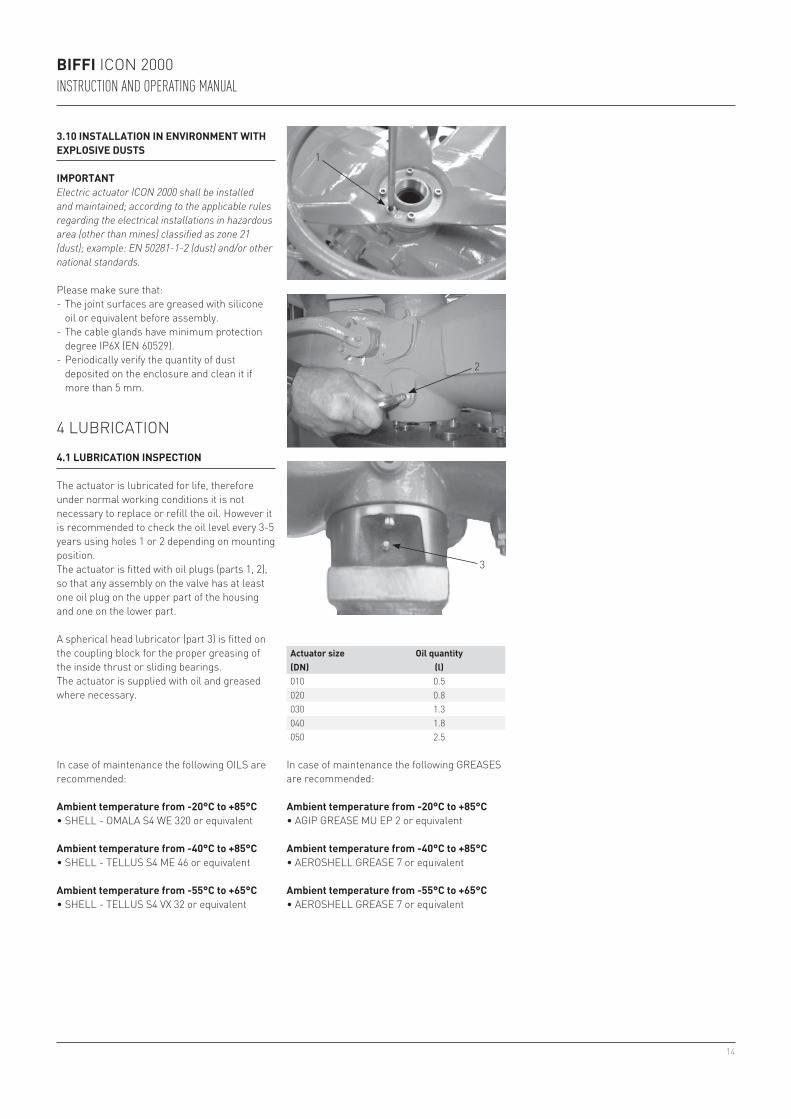
The actuator is lubricated for life, therefore under normal working conditions it is not necessary to replace or refill the oil. However it is recommended to check the oil level every 3-5 years using holes 1 or 2 depending on mounting position.The actuator is fitted with oil plugs (parts 1, 2), so that any assembly on the valve has at least one oil plug on the upper part of the housing and one on the lower part.
A spherical head lubricator (part 3) is fitted on the coupling block for the proper greasing of the inside thrust or sliding bearings.The actuator is supplied with oil and greased where necessary.
Actuator size(DN)
Oil quantity(l)
In case of maintenance the following OILS are recommended:
Ambient temperature from -20°C to +85°C• SHELL - OMALA S4 WE 320 or equivalent
Ambient temperature from -40°C to +85°C• SHELL - TELLUS S4 ME 46 or equivalent
Ambient temperature from -55°C to +65°C• SHELL - TELLUS S4 VX 32 or equivalent
In case of maintenance the following GREASES are recommended:
Ambient temperature from -20°C to +85°C• AGIP GREASE MU EP 2 or equivalent
Ambient temperature from -40°C to +85°C• AEROSHELL GREASE 7 or equivalent
Ambient temperature from -55°C to +65°C• AEROSHELL GREASE 7 or equivalent
15
BIFFI ICON 2000INSTRUCTION AND OPERATING MANUAL
5 OPERATING THE ICON 2000
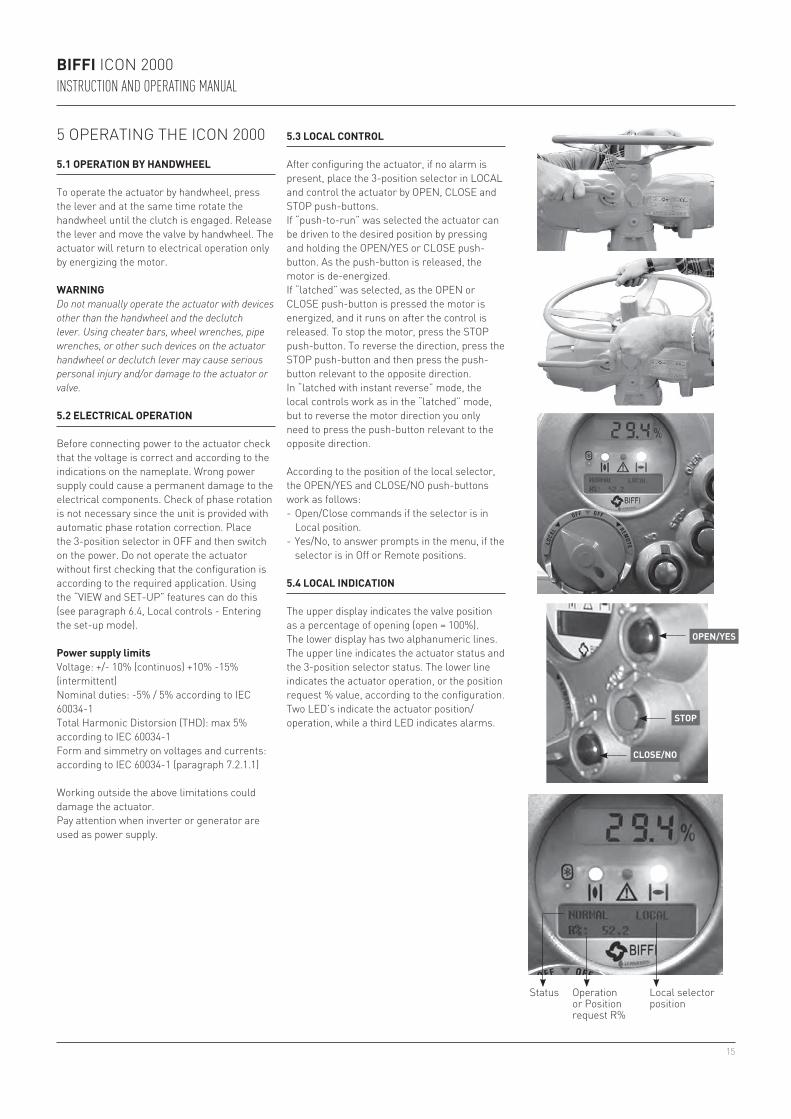
5.1 OPERATION BY HANDWHEEL
To operate the actuator by handwheel, press the lever and at the same time rotate the handwheel until the clutch is engaged. Release the lever and move the valve by handwheel. The actuator will return to electrical operation only by energizing the motor.
WARNINGDo not manually operate the actuator with devices other than the handwheel and the declutch lever. Using cheater bars, wheel wrenches, pipe wrenches, or other such devices on the actuator handwheel or declutch lever may cause serious personal injury and/or damage to the actuator or valve.
5.2 ELECTRICAL OPERATION
Before connecting power to the actuator check that the voltage is correct and according to the indications on the nameplate. Wrong power supply could cause a permanent damage to the electrical components. Check of phase rotation is not necessary since the unit is provided with automatic phase rotation correction. Place the 3-position selector in OFF and then switch on the power. Do not operate the actuator without first checking that the configuration is according to the required application. Using the “VIEW and SET-UP” features can do this (see paragraph 6.4, Local controls - Entering the set-up mode).
Power supply limitsVoltage: +/- 10% (continuos) +10% -15% (intermittent)Nominal duties: -5% / 5% according to IEC 60034-1Total Harmonic Distorsion (THD): max 5% according to IEC 60034-1 Form and simmetry on voltages and currents: according to IEC 60034-1 (paragraph 7.2.1.1)
Working outside the above limitations could damage the actuator.Pay attention when inverter or generator are used as power supply.
5.3 LOCAL CONTROL
After configuring the actuator, if no alarm is present, place the 3-position selector in LOCAL and control the actuator by OPEN, CLOSE and STOP push-buttons.If “push-to-run” was selected the actuator can be driven to the desired position by pressing and holding the OPEN/YES or CLOSE push-button. As the push-button is released, the motor is de-energized.If “latched” was selected, as the OPEN or CLOSE push-button is pressed the motor is energized, and it runs on after the control is released. To stop the motor, press the STOP push-button. To reverse the direction, press the STOP push-button and then press the push-button relevant to the opposite direction.In “latched with instant reverse” mode, the local controls work as in the “latched” mode, but to reverse the motor direction you only need to press the push-button relevant to the opposite direction.
According to the position of the local selector, the OPEN/YES and CLOSE/NO push-buttons work as follows:- Open/Close commands if the selector is in
Local position.- Yes/No, to answer prompts in the menu, if the
selector is in Off or Remote positions.
OPEN/YES
STOP
CLOSE/NO
5.4 LOCAL INDICATION
The upper display indicates the valve position as a percentage of opening (open = 100%).The lower display has two alphanumeric lines.The upper line indicates the actuator status and the 3-position selector status. The lower line indicates the actuator operation, or the position request % value, according to the configuration.Two LED’s indicate the actuator position/operation, while a third LED indicates alarms.
Status Operation or Position request R%
Local selector position
16
BIFFI ICON 2000INSTRUCTION AND OPERATING MANUAL
5.5 LOCK OF THE 3-POSITION SELECTOR
The 3-position selector can be locked in any of its three positions by means of a padlock.
5.6 REMOTE CONTROL
Place the 3-position selector in REMOTE to transfer the actuator control to a remote device. Local OPEN or CLOSE operation will be inhibited. Only local STOP control remains active.Using the “VIEW and SET-UP” features may configure different control modes. The remote controls are opto-coupled.A non-regulated 24 V DC voltage (variable from 23 to 27 V DC, max. 4 W) is available on the actuator terminal board to supply the remote controls or external devices.
5.6.1 Remote commandsUsing the “VIEW and SET-UP” features may configure different control modes.
4 WIRES (see the remote connections diagram shown beside)In “4 wires latched” (OPEN, CLOSE, STOP, COMMON) mode, with the OPEN or CLOSE signal switched to ON, the motor is energized, and it runs on after the signal returns to OFF. To stop the motor, press STOP. To reverse the direction, press STOP and then press the button relevant to the opposite direction. The action of the STOP signal (stop with signal ON or stop with signal OFF) may be reversed using the VIEW and SET-UP features, see paragraph 9.1.4, Remote controls.
3 WIRES (see the remote connections diagram shown beside)With option “3 wires” (OPEN, CLOSE, COMMON), the actuator can be driven in either “push-to-run” or “latched with instant reverse” mode.In “push-to-run” mode, the actuator can be driven to the desired position by switching the OPEN or CLOSE signal to ON. As the signal returns to OFF, the motor is de-energized.In “latched with instant reverse” mode, when the OPEN or CLOSE signal switches to ON, the motor is energized, and it runs on after the signal returns to OFF. If the signal relevant to the opposite direction goes ON, the actuator reverses its direction and maintains the new direction also if the signal returns to OFF.
OPTION A1)
OPTION B1)
OPTION A2)
OPTION B2)
OPTION A3)
OPTION B3)
The circuits associated to the inputs can be supplied by the internally-generated 24 V DC or by an external 20-125 V DC or 20-120 V AC (50/60 Hz).The signal levels are the following:- Minimum ON signal > 20 V DC or 20 V AC
(50/60 Hz).- Maximum ON signal < 125 V DC or 120 V AC
(50/60 Hz).- Maximum OFF signal < 3 V.- Minimum signal duration > 500 ms.- Total current drawn from remote controls
< 25 mA.
2 WIRES (see the remote connections diagram shown beside)With the “2 wires” option 2 different activities may be selected:In “2 wires, signal ON to open”, the actuator opens if the signal switches to ON and closes if the signal goes to OFF. In “2 wires, signal ON to close”, the actuator closes if the signal switches to ON and opens if the signal switches to OFF. This option requires two wires (signal and common).
17
BIFFI ICON 2000INSTRUCTION AND OPERATING MANUAL
5.6.2 Output contactsStandard version- Monitor relay: on the terminal board, the
voltage-free, change-over contacts of the monitor relay are available. The monitor relay indicates that the actuator can be remotely controlled or that there is a problem or condition which prevents remote control of the valve. The conditions that cause the relay to switch over are listed in paragraph 9.1.6, Output relays.
- AS1,2,3,4,5,6,7 relays: on the terminal board, the voltage-free contacts of 7 latching relays are available. The status (make or break) and the conditions that cause the switching of the relay can be viewed and configured by using the “VIEW and SET-UP” features. The status of the latching relays is immediately updated as the associated conditions for change occur. Moreover, the status of the above contacts is cyclically updated (every second).
- AS8 relay: a further voltage-free, change-over contact is available on the terminal board.
The conditions that cause the switching of the relay can be viewed and configured by using the “VIEW and SET-UP” features.
- Contact rating: Max. voltage 250 V AC / 30 V DC: max. current 5 A. Min. voltage 5 V DC: min. current 5 mA.
Special version with highly sensitive gold-plated contact relays supplied on request:- Monitor relay: voltage-free, change-over,
gold-cap silver palladium contacts.- AS1, 2, 3 relays: voltage-free, change-over,
latching, gold-cap silver palladium contacts.- AS4 relay: voltage-free, latching, gold-cap
silver palladium contacts, configurable N.O. or N.C. in the “Output relays” menu.
- AS5, 6 relays: voltage-free, change-over, gold-cap silver palladium contacts.
- The conditions that cause the switching over of the monitor relay and auxiliary relays AS1...AS6 are the same of the standard version and are configurable in the “Output relays” menu.
- AS7, 8 relays: not available.- Contact rating: max voltage 250 V AC;
max current 2 A; min switching capability 10 microA, 10 m V DC.
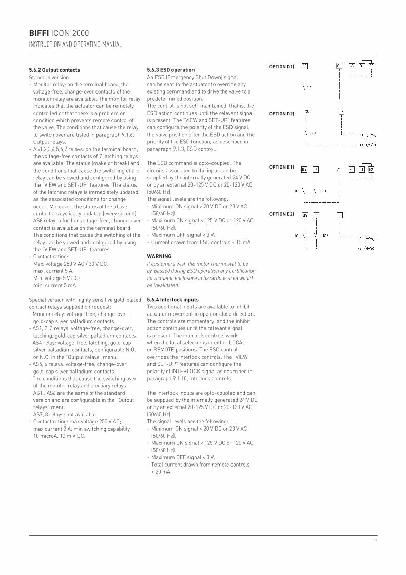
5.6.3 ESD operationAn ESD (Emergency Shut Down) signal can be sent to the actuator to override any existing command and to drive the valve to a predetermined position.The control is not self-maintained, that is, the ESD action continues until the relevant signal is present. The “VIEW and SET-UP” features can configure the polarity of the ESD signal, the valve position after the ESD action and the priority of the ESD function, as described in paragraph 9.1.3, ESD control.
The ESD command is opto-coupled. The circuits associated to the input can be supplied by the internally generated 24 V DC or by an external 20-125 V DC or 20-120 V AC (50/60 Hz).The signal levels are the following:- Minimum ON signal > 20 V DC or 20 V AC
(50/60 Hz).- Maximum ON signal < 125 V DC or 120 V AC
(50/60 Hz).- Maximum OFF signal < 3 V.- Current drawn from ESD controls < 15 mA.
WARNINGIf customers wish the motor thermostat to be by-passed during ESD operation any certification for actuator enclosure in hazardous area would be invalidated.
5.6.4 Interlock inputsTwo additional inputs are available to inhibit actuator movement in open or close direction. The controls are momentary, and the inhibit action continues until the relevant signal is present. The interlock controls work when the local selector is in either LOCAL or REMOTE positions. The ESD control overrides the interlock controls. The “VIEW and SET-UP” features can configure the polarity of INTERLOCK signal as described in paragraph 9.1.10, Interlock controls.
The interlock inputs are opto-coupled and can be supplied by the internally generated 24 V DC or by an external 20-125 V DC or 20-120 V AC (50/60 Hz).The signal levels are the following:- Minimum ON signal > 20 V DC or 20 V AC
(50/60 Hz).- Maximum ON signal < 125 V DC or 120 V AC
(50/60 Hz).- Maximum OFF signal < 3 V.- Total current drawn from remote controls
< 20 mA.
OPTION D1)
OPTION D2)
OPTION E1)
OPTION E2)
18
BIFFI ICON 2000INSTRUCTION AND OPERATING MANUAL
5.7 OPERATING THE ICON 2000 FOR THE FIRST TIME
Before attempting to operate the ICON 2000 for the first time, check that the actuator is correctly mounted on the valve. Place the 3-position selector in OFF and switch the power on. The alphanumeric display shows the following message for about 3 seconds:
5.8 OPTIONAL MODULES
Additional modules can be plugged in the base card of the ICON 2000 to provide the following functions:
5.8.1 Fieldbus interface for remote control via FIELDBUSThis card allows to connect the ICON 2000 to FIELDBUS.The following bus interface cards are available:- Profibus DPVO- Profibus DPV1 with or without redundancy- Foundation Fieldbus- LonWorks- Modbus RTU
A Hardware alarm is generated if the ICON 2000 was set to be equipped with bus card, but the card is damaged or missing. A BUS REPORT is also present in the list of reports if the card is present (see chapter 6). See the specific manuals for instructions and the setting of the above modules.
Then the new message should be:
according to the configuration present in the memory.
If the upper line of the display shows “ALARM OFF”, remove the alarm before going ahead (see paragraph 12.11).If the upper line of the display shows “WARNING OFF”, a warning condition is present. You can go ahead since the ICON 2000 is working well, but some datum is not according to the configured parameters (see paragraph 12.11).If the upper line of the display shows “INT OFF”, an Interlock input is active.If the upper line of the display shows “ESD ON OFF”, the ESD input is active.
If the following message appears, the base card is ICON 2000 v4 type, but the actuator is equipped with an ICON 2000 v0 series terminal board. This may happen if the ICON 2000 v4 base card was supplied as a spare card, to replace the base card of the ICON 2000 v0 series (see the previous revision of instruction manuals relevant to the ICON 2000 and its optional modules).
5.8.2 Ain/Aout cardWith the above card the ICON 2000 is provided with a 4-20 analog input and a 4-20 mA analog output. This card should be plugged on the base card, replacing the “TERMINAL BOARD ADAPTOR” card supplied as standard. A Hardware alarm is generated if the ICON 2000 was set to be equipped with an Ain/Aout card, and the card is damaged or missing. An Ain/Aout REPORT is also present in the list of reports if the card is present (see chapter 6).
or
Set torque limits, position limits and close direction by means of the “stroke limits routine” of the “actuator set-up” menu (see chapter 9).When the stroke limits and the configurations are correct, bring the 3-position selector to LOCAL and drive the actuator to open or closed position (see paragraph 5.3).
Biffi ItaliaICON2000 v4 ntb
NORMAL OFF STOP
NORMAL OFF R%: xxx.x
Biffi ItaliaICON2000 v4 otb
Do not operate the actuator without first checking that the configuration is according to the required application by using the “VIEW and SET-UP” features (see chapter 6/10).
19
B6
B7
B7
C10
B9
B8
0 V
V+
0 V DC
4-20 mA
4-20 mA
0 V
4-20 mA
0 V
20-30V DC
BIFFI ICON 2000INSTRUCTION AND OPERATING MANUAL
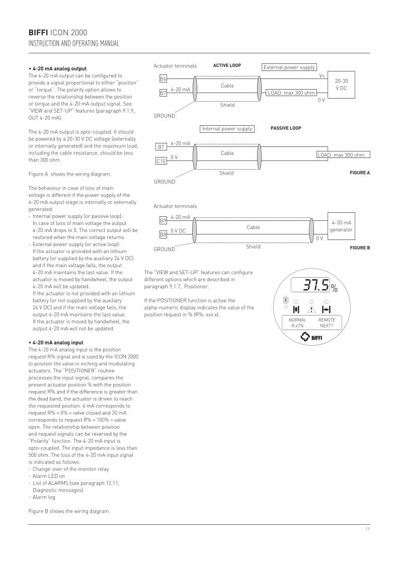
• 4-20 mA analog outputThe 4-20 mA output can be configured to provide a signal proportional to either “position” or “torque”. The polarity option allows to reverse the relationship between the position or torque and the 4-20 mA output signal. See “VIEW and SET-UP” features (paragraph 9.1.9, OUT 4-20 mA).
The 4-20 mA output is opto-coupled. It should be powered by a 20-30 V DC voltage (externally or internally generated) and the maximum load, including the cable resistance, should be less than 300 ohm.
Figure A shows the wiring diagram.
Actuator terminals ACTIVE LOOP
Cable
GROUND
Shield
External power supply
LOAD: max 300 ohm
Internal power supply
Cable
GROUNDShield
LOAD: max 300 ohm
The behaviour in case of loss of main voltage is different if the power supply of the 4-20 mA output stage is internally or externally generated:- Internal power supply (or passive loop): In case of loss of main voltage the output
4-20 mA drops to 0. The correct output will be restored when the main voltage returns.
- External power supply (or active loop): If the actuator is provided with an lithium
battery (or supplied by the auxiliary 24 V DC) and if the main voltage fails, the output 4-20 mA maintains the last value. If the actuator is moved by handwheel, the output 4-20 mA will be updated.
If the actuator is not provided with an lithium battery (or not supplied by the auxiliary 24 V DC) and if the main voltage fails, the output 4-20 mA maintains the last value. If the actuator is moved by handwheel, the output 4-20 mA will not be updated.
• 4-20 mA analog inputThe 4-20 mA analog input is the position request R% signal and is used by the ICON 2000 to position the valve in inching and modulating actuators. The “POSITIONER” routine processes the input signal, compares the present actuator position % with the position request R% and if the difference is greater than the dead band, the actuator is driven to reach the requested position. 4 mA corresponds to request R% = 0% = valve closed and 20 mA corresponds to request R% = 100% = valve open. The relationship between position and request signals can be reversed by the “Polarity” function. The 4-20 mA input is opto-coupled. The input impedance is less than 500 ohm. The loss of the 4-20 mA input signal is indicated as follows:- Change-over of the monitor relay- Alarm LED on- List of ALARMS (see paragraph 12.11,
Diagnostic messages)- Alarm log
Figure B shows the wiring diagram.
Actuator terminals
Cable
GROUND Shield
4-20 mAgenerator
PASSIVE LOOP
FIGURE A
FIGURE B
The “VIEW and SET-UP” features can configure different options which are described in paragraph 9.1.7, Positioner.
If the POSITIONER function is active the alpha-numeric display indicates the value of the position request in % (R%: xxx.x).
NORMAL REMOTER:47% NEXT?

20
BIFFI ICON 2000INSTRUCTION AND OPERATING MANUAL
Ain/Aout cardThis optional card is used in place of the Terminal Board Adaptor (TBA) card when an analog 4-20 mA input and output signal is requested. This card cannot be used in the actuators with terminal board series ICON 2000 v0 (see paragraph 5.7, Operating the ICON 2000 for the first time).
5.9 BASE CARD OF THE ICON 2000 V4
Bottom view of base card
Terminal Board Adaptor card (TBA)
Fieldbus interface cardThe type of card depends on the fieldbus present in the plant.
Base card equipped with fieldbus interface card and Terminal Board Adaptor card.
Top view of base card
Bluetooth™
Potentiometer cardWith this card properly set trough the VIEW and SET-UP menu, the base card works as F01-2000 v4 base card (see VCIOM-01249 Instruction Manual).
21
4
6
1
3
2
5
BIFFI ICON 2000INSTRUCTION AND OPERATING MANUAL
6 LOCAL CONTROLS
6.1 DESCRIPTION OF THE LOCAL OPERATOR INTERFACE
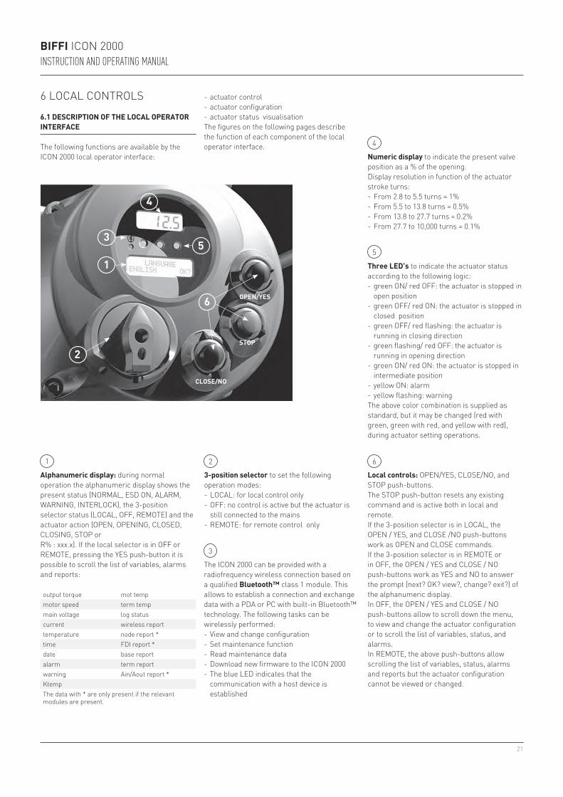
The following functions are available by the ICON 2000 local operator interface: Numeric display to indicate the present valve
position as a % of the opening.Display resolution in function of the actuator stroke turns:- From 2.8 to 5.5 turns = 1%- From 5.5 to 13.8 turns = 0.5%- From 13.8 to 27.7 turns = 0.2%- From 27.7 to 10,000 turns = 0.1%
3-position selector to set the following operation modes:- LOCAL: for local control only- OFF: no control is active but the actuator is
still connected to the mains- REMOTE: for remote control only
Alphanumeric display: during normal operation the alphanumeric display shows the present status (NORMAL, ESD ON, ALARM, WARNING, INTERLOCK), the 3-position selector status (LOCAL, OFF, REMOTE) and the actuator action (OPEN, OPENING, CLOSED, CLOSING, STOP orR% : xxx.x). If the local selector is in OFF or REMOTE, pressing the YES push-button it is possible to scroll the list of variables, alarms and reports:
CLOSE/NO
STOP
OPEN/YES
The ICON 2000 can be provided with a radiofrequency wireless connection based on a qualified Bluetooth™ class 1 module. This allows to establish a connection and exchange data with a PDA or PC with built-in Bluetooth™ technology. The following tasks can be wirelessly performed:- View and change configuration- Set maintenance function- Read maintenance data- Download new firmware to the ICON 2000- The blue LED indicates that the
communication with a host device is established
Local controls: OPEN/YES, CLOSE/NO, and STOP push-buttons.The STOP push-button resets any existing command and is active both in local and remote.If the 3-position selector is in LOCAL, the OPEN / YES, and CLOSE /NO push-buttons work as OPEN and CLOSE commands.If the 3-position selector is in REMOTE or in OFF, the OPEN / YES and CLOSE / NO push-buttons work as YES and NO to answer the prompt (next? OK? view?, change? exit?) of the alphanumeric display.In OFF, the OPEN / YES and CLOSE / NO push-buttons allow to scroll down the menu, to view and change the actuator configuration or to scroll the list of variables, status, and alarms.In REMOTE, the above push-buttons allow scrolling the list of variables, status, alarms and reports but the actuator configuration cannot be viewed or changed.
- actuator control- actuator configuration- actuator status visualisationThe figures on the following pages describe the function of each component of the local operator interface.
Three LED’s to indicate the actuator status according to the following logic:- green ON/ red OFF: the actuator is stopped in
open position- green OFF/ red ON: the actuator is stopped in
closed position- green OFF/ red flashing: the actuator is
running in closing direction- green flashing/ red OFF: the actuator is
running in opening direction- green ON/ red ON: the actuator is stopped in
intermediate position- yellow ON: alarm- yellow flashing: warningThe above color combination is supplied as standard, but it may be changed (red with green, green with red, and yellow with red), during actuator setting operations.
1
3
2
4
5
6
output torque mot tempmotor speed term tempmain voltage log statuscurrent wireless reporttemperature node report *time FDI report *date base reportalarm term reportwarning Ain/Aout report *KtempThe data with * are only present if the relevant modules are present.
22
BIFFI ICON 2000INSTRUCTION AND OPERATING MANUAL
The warning condition occurs when a variable reaches a critical value and/or a maintenance action is required, but the actuator control functions are still available. The alarm condition occurs when a variable is out of the acceptable range and the actuator control functions are not available.
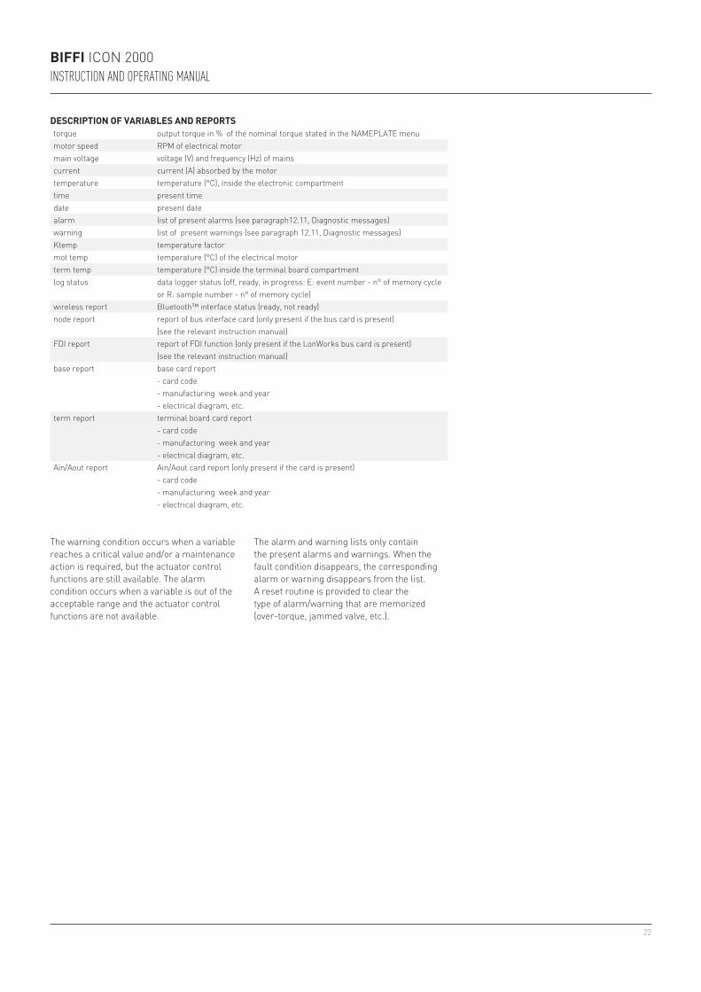
The alarm and warning lists only contain the present alarms and warnings. When the fault condition disappears, the corresponding alarm or warning disappears from the list. A reset routine is provided to clear the type of alarm/warning that are memorized (over-torque, jammed valve, etc.).
DESCRIPTION OF VARIABLES AND REPORTStorque output torque in % of the nominal torque stated in the NAMEPLATE menumotor speed RPM of electrical motormain voltage voltage (V) and frequency (Hz) of mainscurrent current (A) absorbed by the motortemperature temperature (°C), inside the electronic compartmenttime present timedate present datealarm list of present alarms (see paragraph12.11, Diagnostic messages)warning list of present warnings (see paragraph 12.11, Diagnostic messages)Ktemp temperature factormot temp temperature (°C) of the electrical motorterm temp temperature (°C) inside the terminal board compartmentlog status data logger status (off, ready, in progress: E: event number - n° of memory cycle
or R: sample number - n° of memory cycle)wireless report Bluetooth™ interface status (ready, not ready)node report report of bus interface card (only present if the bus card is present)
(see the relevant instruction manual)FDI report report of FDI function (only present if the LonWorks bus card is present)
(see the relevant instruction manual)base report base card report
- card code- manufacturing week and year- electrical diagram, etc.
term report terminal board card report- card code- manufacturing week and year- electrical diagram, etc.
Ain/Aout report Ain/Aout card report (only present if the card is present)- card code- manufacturing week and year- electrical diagram, etc.
23
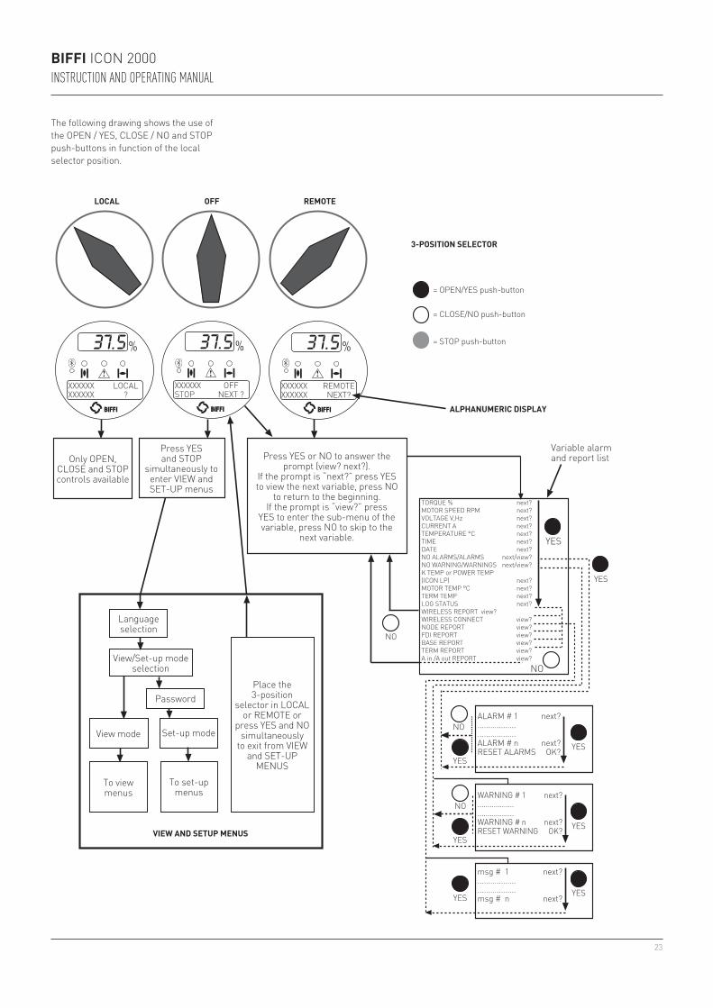
The following drawing shows the use of the OPEN / YES, CLOSE / NO and STOP push-buttons in function of the local selector position.
LOCAL OFF REMOTE
3-POSITION SELECTOR
= OPEN/YES push-button
= CLOSE/NO push-button
= STOP push-button
ALPHANUMERIC DISPLAY
Only OPEN, CLOSE and STOP controls available
Language selection
View mode Set-up mode
To view menus
To set-up menus
View/Set-up mode selection
Place the 3-position
selector in LOCAL or REMOTE or
press YES and NO simultaneously
to exit from VIEW and SET-UP
MENUS
VIEW AND SETUP MENUS
Press YES and STOP
simultaneously to enter VIEW andSET-UP menus
Press YES or NO to answer the prompt (view? next?).
If the prompt is “next?” press YES to view the next variable, press NO
to return to the beginning.If the prompt is “view?” press
YES to enter the sub-menu of the variable, press NO to skip to the
next variable.
YES
YES
YESYES
YES
YES
YES
NO
NO
YES
NO
Variable alarm and report list
TORQUE % next?MOTOR SPEED RPM next?VOLTAGE V,Hz next?CURRENT A next?TEMPERATURE °C next?TIME next?DATE next?NO ALARMS/ALARMS next/view?NO WARNING/WARNINGS next/view?K TEMP or POWER TEMP (ICON LP) next?MOTOR TEMP °C next?TERM TEMP next?LOG STATUS next?WIRELESS REPORT view?WIRELESS CONNECT view?NODE REPORT view?FDI REPORT view?BASE REPORT view?TERM REPORT view?A in /A out REPORT view?
ALARM # 1 next?....................................ALARM # n next?RESET ALARMS OK?
WARNING # 1 next?....................................WARNING # n next?RESET WARNING OK?
msg # 1 next?....................................msg # n next?
XXXXXX REMOTEXXXXXX NEXT?
XXXXXX OFFSTOP NEXT ?
XXXXXX LOCALXXXXXX ?
Password
BIFFI ICON 2000INSTRUCTION AND OPERATING MANUAL
NO
24
BIFFI ICON 2000INSTRUCTION AND OPERATING MANUAL
6.2 CONFIGURATION OPTIONS
The ICON 2000 actuator can be totally configured from the local interface by means of a series of menus that can be selected from the alphanumeric display. The operator is guided through the different displays by answering YES or NO to the appropriate prompt (change? OK?, view?, next?, etc.) in the right corner of the lower row of the alphanumeric display.To access the menus: set the local selector in OFF and then simultaneously press OPEN/YES and STOP. The alphanumeric display will now show the present language. Press YES if the language is correct, press NO to scroll the list of available languages and then YES to select.After choosing the language, the next step is the selection among view and set-up mode. Use “View” mode to see the actuator configuration, and use “Set-up” mode to change the present configuration. Unauthorized access to the set-up mode is prevented by a 4-character alphanumeric password. The actuator is supplied by Biffi with the default password “0 0 0 0”.Once the correct password has been entered, the actuator parameters can be configured.The present password can also be modified by the “set password” routine in the Maintenance menu. After entering the new password, the old one ceases to be valid, so it is important to record the password in a secure location for future retrieval.
The configuration functions (view and set-up mode) are grouped in 4 main menus:Actuator set-up, Nameplate, Valve data, Maintenance.
NameplateThis menu includes a series of data identifying the actuator characteristics, service, and utilisation mode. The data are entered by the manufacturer and can only be viewed (i.e., this menu is only available in View mode).List of routines:- serial number- actuator type- torque/thrust- actuator speed- power supply- motor data- test date- wiring diagram- enclosure- certificate- lubricant- revision- torque sensor
Valve dataThis menu includes a series of data relevant to the valve. The valve manufacturer and end user should enter the data.List of routines:- tag name (max 28 characters) - manufacturer (max 28 characters)- break OP torque (max 28 characters)- serial number (max 28 characters)- break CL torque (max 28 characters)- max stem thrust (max 28 characters)- flange type (max 28 characters)
MaintenanceThis menu includes all diagnostic and historic data which can help the operator in case of failure or during maintenance operations. The Maintenance menu also includes the “Set password” routine.
List of routines:
• Set-up mode- set new password- clear alarm log- set torque profile reference- set torque curve reference- clear recent data log- set maintenance date- set data logger
• View mode- alarm log- torque profile- torque curve- operation log- maintenance date- data logger
Actuator set-upThis menu includes the routines that allow the actuator to be configured according to the requested control mode and to the valve it is mounted on.- stroke limits- torque set-up- ESD set-up- remote controls- local controls- output relays- positioner *- fail safe *- out 4-20 mA *- interlock- 2-speed timer- Bus *- miscellaneous
The routines with * are only available if the relevant modules are present. If bus interface is LonWorks, the “BUS” routine changes to “FDI control”.
The parameters appear on the alphanumeric display in the same order both in view and set-up mode. At the end of each routine the program will automatically return to the beginning of the routine, and the operator can choose to either re-enter (by pressing YES) or to move on to a next routine (by pressing NO).
25
BIFFI ICON 2000INSTRUCTION AND OPERATING MANUAL
6.3 ENTERING THE VIEW MODE
The existing actuator configuration should be checked before commissioning. The parameters are configured in factory according to a standard setting, or to customer requirements. In view mode, no password is requested, but no change of parameters can be made.• Ensure the electrical main power is applied.• Move the 3-position selector to OFF and then
simultaneously press OPEN/YES and STOP.• The display shows the present language.
Press YES to confirm or NO to scroll the list of available languages. Press YES to select a new language. Press YES to confirm.
• Press NO to scroll the list of available menus (actuator set-up, nameplate, valve data, maintenance) and then press YES to select the desired menu.
• Press NO to scroll the list of available routines and press YES to select the routine where the parameter to be changed is located.
• Press NO to scroll the list of parameters and press YES to view the value.
6.4 ENTERING THE SET-UP MODE
To change the existing settings or to set the stroke limits it is necessary to enter the correct password.• Ensure the electrical main power (or the
external auxiliary supply) is applied.• Move the 3-position selector to OFF and then
simultaneously press OPEN/YES and STOP.• The display shows the present language.
Press YES to confirm or NO to scroll the list of available languages. Press YES to select. Press YES to confirm the chosen language.
• Press NO when the message is “VIEW MODE OK?”. Press YES to answer prompt “ENTER PASSWORD OK?”.
• Enter password. Enter one digit at a time. Press YES if digit is correct, press NO to scroll the list of available characters and then press YES when the character is correct. Enter 4 digits. After entering the last digit, the microprocessor checks the password. If it is correct the messages “PASSWORD CORRECT” and then “SET-UP MODE OK?” appear. Press YES.
• Press NO to scroll the list of available menus (actuator set-up, valve data, maintenance) and press YES to select the desired menu.
• Press NO to scroll the list of available routines and press YES to select the routine where the parameter to be changed is located.
• Press YES and NO to answer the prompt on the display and change the parameter.
• If the password is wrong the message “PASSWORD WRONG” appears and set-up mode will not available.
6.5 EXIT FROM VIEW AND SET-UP MODE
The following conditions cause the exit from view and set-up mode:• Move the 3-position selector to LOCAL or
REMOTE.• Answer YES when the display asks
“EXIT OK?”.• Press YES and NO simultaneously.• Automatic exit after 90 minutes without any
parameter change or view.• Remove the electrical power from the unit.
All settings are automatically saved to a non-volatile memory and retained also if the electrical power is removed from the actuator.All ICON 2000 actuators are configured before shipping with a standard default setting unless alternatives were requested on order. In case of difficulty during commissioning, the default setting can be re-instated by the appropriate function in the routine ”miscellaneous” of the actuator set-up menu. The actuator returns to its original configuration and commissioning can be resumed.
26
BIFFI ICON 2000INSTRUCTION AND OPERATING MANUAL
XXXX
XX
OFF
STOP
N
EXT?
LAN
GUAG
E EN
GLIS
HOK
?VI
EW M
ODE
OK?
LANG
UAGE
FRA
NCAI
SOK
?EN
TER
PASS
WOR
DOK
?
0 “0
” 0 0
DIGI
T 2
OK?
0 0
“0” 0
DIGI
T 3
OK?
0 0
0 “0
”DI
GIT
4 OK
?“0
” 0 0
0DI
GIT
1 OK
?
“Z” 0
0 0
DIGI
T 1
OK?
Z “K
” 0 0
DIGI
T 2
OK?
Z K
“9” 0
DIGI
T 3
OK?
Z K
9 “R
”DI
GIT
4 OK
?
SETU
P M
ODE
OK?
PASS
WOR
D CO
RREC
T
PASS
WOR
D W
RON
G
DISP
LAY
LOCA
LRE
MOT
EPr
ess
NO
until
the
desi
red
lang
uage
ap
pear
san
dth
enpr
ess
YES
FROM
EXI
T?
TO V
IEW
MEN
U
Pres
s N
O un
til th
e de
sire
d ch
arac
ter a
ppea
rs a
nd th
en p
ress
YES
YES
YES
YES
NO
YES
YES
YES
NO
YES
NO
NO
YES
YES
YES
NO
YES
YES
YES
NO
NO
STOP
OFF
3-PO
SITI
ON S
ELEC
TOR
TO S
ETUP
M
ENU
FROM
EXI
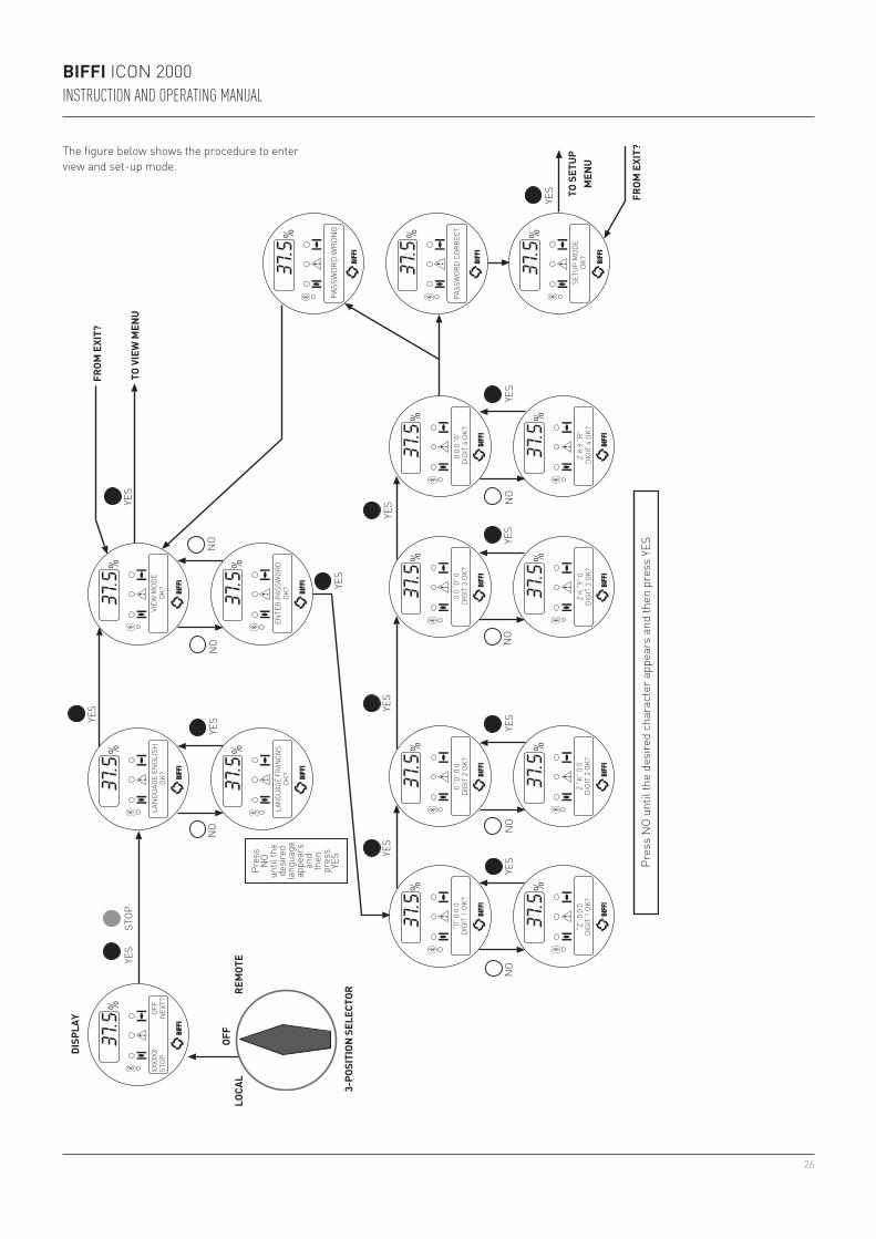
T?The figure below shows the procedure to enter view and set-up mode.
27
BIFFI ICON 2000INSTRUCTION AND OPERATING MANUAL
XXXX
XX
OFF
STOP
N
EXT?
DISP
LAY
LOCA
LRE
MOT
E
Rout
ines
:- T
ag n
ame
chan
ge?
- Ser
ial n
umbe
r ch
ange
?- M
anuf
actu
rer
chan
ge?
- Bre
ak O
P to
rque
ch
ange
?- B
reak
CL
torq
ue
chan
ge?
- Max
ste
m th
rust
ch
ange
?- F
lang
e ty
pe
chan
ge?
Rout
ines
:- s
trok
e lim
its
chan
ge?
- tor
que
set-
up
chan
ge?
- ESD
set
-up
chan
ge?
- Rem
ote
cont
rols
ch
ange
?- L
ocal
con
trol
s ch
ange
?- O
utpu
t rel
ays
chan
ge?
- Pos
ition
er *
ch
ange
?- F
ail s
afe
* ch
ange
?- O
ut 4
-20
mA
* ch
ange
?- I
nter
lock
ch
ange
?- 2
-spe
ed ti
mer
ch
ange
?- B
us *
ch
ange
?- M
isce
llane
ous
chan
ge?
To e
xit f
rom
SET
UP m
enu
pres
sYE
S an
d N
O si
mul
tane
ousl
y or
mov
e th
e 3-
posi
tion
sele
ctor
toLO
CAL
or R
EMOT
E
1. R
outin
es w
ith *
are
onl
y ava
ilabl
e if
the
rele
vant
m
odul
es a
re p
rese
nt2.
Nam
epla
te m
enu
not a
vaila
ble
in S
et-u
p m
ode
ENTE
RPA
SSW
ORD
TO V
IEW
MEN
U
Pres
s YE
S or
NO
to a
nsw
er th
e ap
prop
riate
pro
mpt
s (c
hang
e? O
K?, e
tc.)
SELE
CTLA
NGU
AGE
Rout
ines
:- S
et p
assw
ord
chan
ge?
- Cle
ar a
larm
log
OK?
- Set
torq
ue p
rofil
e re
fere
nce
OK?
- Set
torq
ue c
urve
refe
renc
e OK
?- C
lear
rece
nt d
ata
log
OK?
- Mai
nten
ance
dat
e ch
ange
?- D
ata
logg
er
chan
ge?
YES
YES
YES
YES
NO
NO
NO
NO
YES
STOP
NO
NO
NO
NO
YES
OFF
3-PO
SITI
ON S
ELEC
TOR
VALV
E DA
TACH
ANGE
?AC
TUAT
OR S
ETUP
CHAN
GE?
SETU
P M
ODE
OK?
MAI
NTE
NAN
CECH
ANGE
?EX
IT?
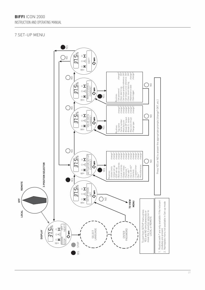
7 SET-UP MENU
28
BIFFI ICON 2000INSTRUCTION AND OPERATING MANUAL
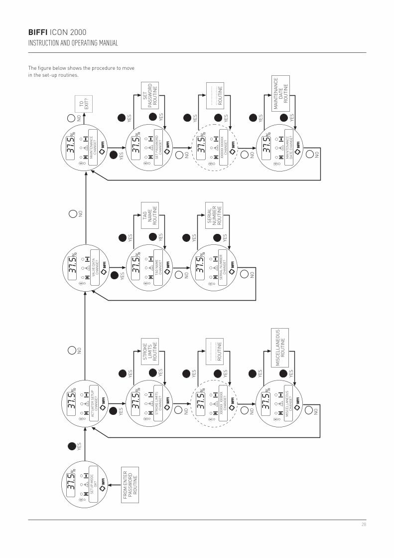
The figure below shows the procedure to move in the set-up routines.
STRO
KE L
IMIT
SCH
ANGE
?
XXXX
XX X
XXXX
XCH
ANGE
?SE
RIAL
NUM
BER
CHAN
GE?
TAG
NAM
ECH
ANGE
?
VALV
E DA
TACH
ANGE
?
XXXX
XX X
XXXX
XCH
ANGE
?
MAI
NTE
NAN
CEDA
TE C
HAN
GE?
SET
PASS
WOR
DCH
ANGE
?
MAI
NTE
NAN
CECH
ANGE
?
MIS
CELL
ANEO
USCH
ANGE
?
ACTU
ATOR
SET
UPCH
ANGE
?SE
TUP
MOD
EOK
?
YES
YES
NO
NO
NO
YES
YES
YES
YES
YES
YES
YES
YES
YES
YES
YES
YES
YES
YES
YES
NO
NO
NO NO
NO
YES
NO
YES
YES
NO
NO
MIS
CELL
ANEO
USRO
UTIN
E
......
......
....
......
......
....
ROUT
INE
SERI
AL
NUM
BER
ROUT
INE
......
......
....
......
......
....
ROUT
INE
SET
PASS
WOR
DRO
UTIN
E
TO EXIT
?
MAI
NTE
NAN
CEDA
TERO
UTIN
E
TAG
NAM
ERO
UTIN
E
STRO
KELI
MIT
SRO
UTIN
E
FROM
EN
TER
PASS
WOR
DRO
UTIN
E
29
BIFFI ICON 2000INSTRUCTION AND OPERATING MANUAL
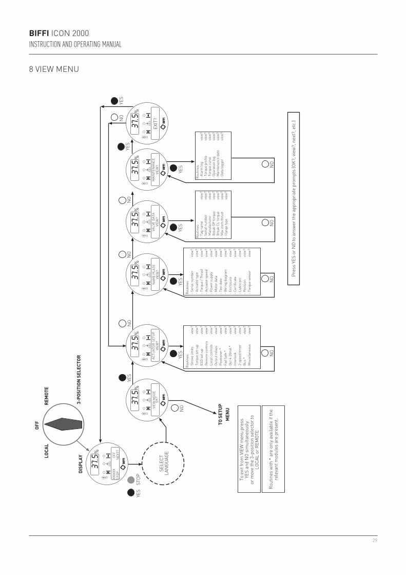
8 VIEW MENU
To e
xit f
rom
VIE
W m
enu
pres
s YE
S an
d N
O si
mul
tane
ousl
y or
mov
e th
e 3-
posi
tion
sele
ctor
to
LOCA
L or
REM
OTE
Rout
ines
with
* a
re o
nly a
vaila
ble
if th
e re
leva
nt m
odul
es a
re p
rese
nt.
TO S
ETUP
M
ENU
Pres
s YE
S or
NO
to a
nsw
er th
e ap
prop
riate
pro
mpt
s (O
K?, v
iew
?, n
ext?
, etc
.)
SELE
CTLA
NGU
AGE
DISP
LAYLO
CAL
REM
OTE
YES
YES
NO
NO
NO
YES
YES
YES
YES
YES
NO
NO
NO
NO
NO
YES
NO
STOP
OFF
3-PO
SITI
ON S
ELEC
TOR
XXXX
XX
OFF
STOP
N
EXT?
VIEW
MOD
EOK
?AC
TUAT
OR S
ETUP
VIEW
?N
AME
PLAT
EVI
EW?
VALV
E DA
TAVI
EW?
MAI
NTE
NAN
CEVI
EW?
EXIT
?
Rout
ines
:- S
trok
e lim
its
view
?- T
orqu
e se
t-up
vie
w?
- ESD
set
-up
view
?- R
emot
e co
ntro
ls
view
?- L
ocal
con
trol
s vie
w?
- Out
put r
elay
s vie
w?
- Pos
ition
er *
vie
w?
- Fai
l Saf
e *
view
?- O
ut 4
-20m
A *
view
?- I
nter
lock
vie
w?
- 2-s
peed
tim
er
view
?- B
us *
vie
w?
- Mis
cella
neou
s vie
w?
Rout
ines
:- S
eria
l num
ber
view
?- A
ctua
tor t
ype
view
?- T
orqu
e / T
hrus
t vie
w?
- Act
uato
r spe
ed
view
?- P
ower
sup
ply
view
?- M
otor
dat
a vie
w?
- Tes
t dat
e vie
w?
- Wiri
ng d
iagr
am
view
?- E
nclo
sure
vie
w?
- Cer
tific
ate
view
?- L
ubric
ant
view
?- R
evis
ion
view
?- T
orqu
e se
nsor
vie
w?
Rout
ines
:- T
ag n
ame
view
?- S
eria
l num
ber
view
?- M
anuf
actu
rer
view
?- B
reak
OP
torq
ue
view
?- B
reak
CL
torq
ue
view
?- M
ax s
tem
thru
st
view
?- F
lang
e ty
pe
view
?
Rout
ines
:- A
larm
log
view
?- T
orqu
e pr
ofile
vie
w?
- Tor
que
curv
e vie
w?
- Ope
ratio
n lo
g vie
w?
- Mai
nten
ance
dat
e vie
w?
- Dat
a lo
gger
vie
w?
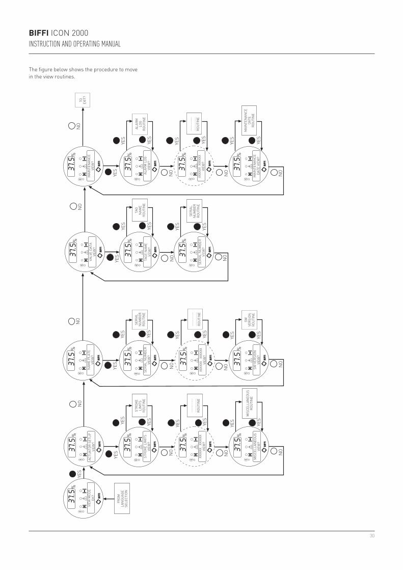
30
BIFFI ICON 2000INSTRUCTION AND OPERATING MANUAL
The figure below shows the procedure to move in the view routines.
VIEW
MOD
EOK
?AC
TUAT
OR S
ETUP
VIEW
?N
AME
PLAT
EVI
EW?
STRO
KE L
IMIT
SVI
EW?
XXXX
XX
XXXX
XXVI
EW?
MIS
CELL
ANEO
US
VIEW
?
YES
YES NO
NO NO
YES
YES
YES
YES
NO NO
YES
YES
YES
YES
YES
YES
YES
YES
YES
SERI
AL N
UMBE
RVI
EW?
VALV
E DA
TAVI
EW?
MAI
NTE
NAN
CEVI
EW?
ALAR
M L
OGVI
EW?
XXXX
XX X
XXXX
XVI
EW?
MAI
NTE
NAN
CEDA
TE V
IEW
?
TAGE
NAM
EVI
EW?
SERI
AL N
UMBE
RVI
EW?
XXXX
XX
XXXX
XXVI
EW?
SW V
ERSI
ONVI
EW?
NO
NO N
O
YES
YES
YES
YES
YES
NO
NO
NO
YES
NO
NO
NO
YES
YES
YES
YES
YES
YES
NO
......
......
....
......
......
....
ROUT
INE
......
......
....
......
......
....
ROUT
INE
......
......
....
......
......
....
ROUT
INE
MAI
NTE
NAN
CEDA
TERO
UTIN
E
SERI
ALN
UMBE
RRO
UTIN
E
TAG
NAM
ERO
UTIN
E
ALAR
MLO
GRO
UTIN
E
TO EXIT
?
SERI
ALN
UMBE
RRO
UTIN
E
MIS
CELL
ANEO
USRO
UTIN
ESW
VERS
ION
ROUT
INE
STRO
KELI
MIT
SRO
UTIN
E
FROM
LAN
GUAG
E SE
LECT
ION
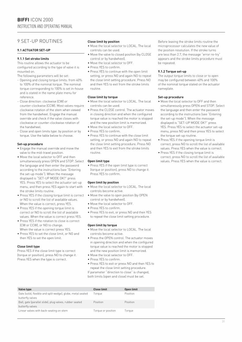
31
BIFFI ICON 2000INSTRUCTION AND OPERATING MANUAL
Set-up procedure• Engage the manual override and move the
valve to the mid-travel position.• Move the local selector to OFF and then
simultaneously press OPEN and STOP. Select the language and then enter the password according to the instructions (see “Entering the set-up mode”). When the message displayed is “SET-UP MODE OK?” press YES. Press YES to select the actuator set-up menu, and then press YES again to start with the stroke limits routine.
• Press YES if the closing torque limit is correct or NO to scroll the list of available values. When the value is correct, press YES.
• Press YES if the opening torque limit is correct or NO to scroll the list of available values. When the value is correct press YES.
• Press YES if the rotation to close is correct (CW or CCW), or NO to change.
When the value is correct press YES.• Press YES to set the close limit, or NO and
then YES to set the open limit.
Close limit typePress YES if the close limit type is correct (torque or position), press NO to change it.Press YES when the type is correct.
Close limit by position• Move the local selector to LOCAL. The local
controls can be used.• Move the valve to closed position (by CLOSE
control or by handwheel).• Move the local selector to OFF.• Press YES to confirm.• Press YES to continue with the open limit
setting, or press NO and again NO to repeat the close limit setting procedure. Press NO and then YES to exit from the stroke limits routine.
Close limit by torque• Move the local selector to LOCAL. The local
controls can be used.• Press the CLOSE control. The actuator moves
in closing direction and when the configured torque value is reached the motor is stopped and the new position limit is memorized.
• Move the local selector to OFF.• Press YES to confirm.• Press YES to continue with the close limit
setting, or press NO and again NO to repeat the close limit setting procedure. Press NO and then YES to exit from the stroke limits routine.
Open limit type• Press YES if the open limit type is correct
(torque or position), press NO to change it. Press YES to confirm.
Open limit by position• Move the local selector to LOCAL. The local
controls become active.• Move the valve to open position (by OPEN
control or by handwheel).• Move the local selector to OFF.• Press YES to confirm.• Press YES to exit, or press NO and then YES
to repeat the close limit setting procedure.
9 SET-UP ROUTINES
9.1 ACTUATOR SET-UP
9.1.1 Set stroke limitsThis routine allows the actuator to be configured according to the type of valve it is mounted on.The following parameters will be set:- Opening and closing torque limits: from 40%
to 100% of the nominal torque. The nominal torque corresponding to 100% is set in-house and is stated in the name plate menu for reference.
- Close direction: clockwise (CW) or counter-clockwise (CCW). Most valves require clockwise rotation of the stem when viewed from the handwheel. Engage the manual override and check if the valve closes with clockwise or counter-clockwise rotation of the handwheel.
- Close and open limits type: by position or by torque. Use the table below to choose.
Valve type Close limit Open limitGate (solid, flexible and split wedge), globe, metal seated butterfly valves
Torque Position
Ball, gate (parallel slide), plug valves, rubber seated butterfly valves
Position Position
Linear valves with back-seating on stem Torque or position Torque
Open limit by torque• Move the local selector to LOCAL. The local
controls become active.• Press the OPEN control. The actuator moves
in opening direction and when the configured torque value is reached the motor is stopped and the new position limit is memorized.
• Move the local selector to OFF.• Press YES to confirm.• Press YES to exit or press NO and then YES to
repeat the close limit setting procedure.If parameter “direction to close” is changed, both limits (open and close) must be set.
Set-up procedure• Move the local selector to OFF and then
simultaneously press OPEN and STOP. Select the language and then enter the password according to the instructions (see “Entering the set-up mode”). When the message displayed is “SET-UP MODE OK?” press YES. Press YES to select the actuator set-up menu, press NO and then press YES to select the torque set-up routine.
• Press YES if the opening torque limit is correct, press NO to scroll the list of available values. Press YES when the value is correct.
• Press YES if the closing torque limit is correct, press NO to scroll the list of available values. Press YES when the value is correct.
Before leaving the stroke limits routine the microprocessor calculates the new value of the position resolution. If the stroke turns are less than 2.7, the message “error re-try” appears and the stroke limits procedure must be repeated.
9.1.2 Torque set-upThe output torque limits to close or to open may be configured between 40% and 100% of the nominal torque stated on the actuator nameplate.
32
BIFFI ICON 2000INSTRUCTION AND OPERATING MANUAL
Configuration procedure• Move the local selector to OFF and then
simultaneously press OPEN and STOP. Select the language and then enter the password according to the instructions (see “Entering the set-up mode”). When the message displayed is “SET-UP MODE OK?” press YES. Press YES to select actuator set-up menu, press NO to scroll the list of available routines and then press YES to select ESD set-up.
• Press YES if the ESD action is correct, or press NO to scroll the list of available options (off, open, close, stay-put, go to position xx %). Press YES to select the desired option.
• Press either YES or NO to select the signal type (present, absent).
• Press YES to change ESD priority with reference to the following signals or status:
- (*) Motor thermostat alarm. Choosing ESD > THERMOSTAT, the ESD action will be carried out also in case of motor over-heating. Vice-versa, if ESD < THERMOSTAT was chosen, the ESD action will not be done in case of motor over-heating.
- (*) Torque limit tripped. Choosing ESD > TORQUE LIMIT, the ESD action will be carried out also in case of torque alarm. Vice-versa, if ESD < TORQUE LIMIT was chosen, the ESD action will not be done in case of torque alarm.
- (*) Local stop pressed. Choosing ESD > LOCAL STOP, the ESD action will override the local STOP signal. Vice-versa, if ESD < LOCAL STOP was chosen, the ESD action will not be performed if the local STOP push-button is pressed.
The factory configuration is the following: action: CLOSE, signal type: PRESENT, priorities: ESD > LOCAL CONTROLS, ESD > 2-SPEED TIMER, ESD < all other cases.
9.1.3 ESD controlAn ESD signal can be connected to the actuator to override any existing command and drive the valve to a predetermined position. The ESD control is not self-maintained: the ESD action is only performed if the relevant input is active. The ESD control is active when the 3-position selector is in REMOTE and no alarm is present.
WARNINGThe user may select ESD to override the situations indicated by (*). If these situations occur and if “ESD > ...” is configured, the actuator may be damaged. Therefore, selecting “ESD > ...” will invalidate the warranty.
Function “ESD priority” allows the ESD command to override the following additional situations: (*) motor thermostat alarm, (*) torque limit tripped, (*) local stop pressed, 3-position selector in local, 2-speed timer, (*) 3-position selector in OFF.
9.1.4 Remote controlsThe actuator may be remotely controlled by 4, or 3, or 2 wires depending on the connection made on the terminal board of the actuator. The following options are available:- 4 wires latched: requires 2 momentary
signals (since the control is self-maintained) to open or close and one signal to stop in mid-travel. The action of the stop signal can be reversed (stop when signal is On [MAKE] or stop when signal is Off [BREAK]).
- 3 wires latched instant reverse: requires 2 momentary signals (since the control is
self-maintained) to open or close. Reverse momentary signal reverses the direction.
- 3 wires momentary: requires 2 push-to-run type signals (since the control is not
self-maintained) to open or close.- 2 wires open if signal On: requires signal On
to open and no signal to close.- 2 wires open if signal Off: requires signal Off
to open and signal On to close.By selecting the option Off, the remote controls are disabled.Configuration should be done during actuator set-up.
Configuration procedure• Move the local selector to OFF and then
simultaneously press OPEN and STOP. Select the language and then enter the password according to the instructions (see “Entering the set-up mode”). When the message displayed is “SET-UP MODE OK?” press YES. Press YES to select actuator set-up menu, press NO to scroll the list of available routines and then press YES to select Remote controls.
- Local selector in LOCAL. Choosing ESD > LOCAL CONTROLS, the ESD action will be carried out also when the local selector is in LOCAL. Vice-versa, if ESD < LOCAL CONTROLS was chosen, the ESD action will not be performed if the 3-position selector is in LOCAL.
- 2-speed timer. Choosing ESD > 2-speed timer, the 2-speed timer function will be inhibited during ESD action. Vice-versa, if ESD < 2-speed timer was chosen, the 2-speed timer function will be active during ESD action.
- (*) Local selector in OFF. By choosing ESD > OFF, the ESD action will be carried out also when the local selector is in OFF. Vice-versa, if ESD < OFF was chosen, the ESD action will not be performed if the 3-position selector is in OFF.
• Press YES if the control mode is correct or NO to scroll the list of available options:
4 wires, 3 wires, 2 wires, off. Press YES to select the desired option. If 4 wires was chosen use YES and NO to select the STOP signal: set MAKE to stop when signal is on and set BREAK to stop when signal is off. If “3 wires” was chosen, use YES or NO to answer the prompt on the display and choose among “push-to-run” or “latched instant reverse” control modes. If “2 wires” was chosen, use YES and NO to choose among “open if signal ON” or “open if signal OFF” control modes.
33
BIFFI ICON 2000INSTRUCTION AND OPERATING MANUAL
Configuration procedure• Move the local selector to OFF and then
simultaneously press OPEN and STOP. Select the language and then enter the password according to the instructions (see “Entering the set-up mode”). When the message displayed is “SET-UP MODE OK?” press YES. Press YES to select the actuator set-up menu, press NO to scroll the list of available routines and then press YES to select Local controls.
• Press YES to change control mode, or press NO to proceed to LED’s color setting.
Control mode• Press YES if the display shows the correct
control mode or press NO to scroll the list of available options (push-to-run, latched). Press YES to confirm.
Option "push-to-run rel. AS5-6" is used when a remote enabling of local commands is required. With the local selector in LOCAL, pressing the OPEN or CLOSE local push-buttons causes relays AS5 or AS6 to switch, but no command is sent to motor. The control PLC should read the status of the above-mentioned relays and send an open or close command on the remote inputs (see paragraph 5.6, push-to-run mode; see relevant electrical diagram when the option is used).
LED’s color• Press YES if the color of the open LED is
correct. Press NO to change it, then YES to confirm.
• Press YES if the color of the close LED is correct. Press NO to change it, then YES to confirm.
• Press YES if the color of the alarm LED is correct. Press NO to change it, then YES to confirm.
9.1.6 Output relays
Monitor relayThe voltage-free, change-over, contacts of the monitor relay indicate that the actuator is either available for remote control or that a problem or a condition preventing remote control of the valve exists.
The following situation can be configured individually to switch-over the monitor relay:- motor over-temperature- over-torque- jammed valve- LOCAL/OFF selected- manual operation- ESD signal on (ESD-EFS)- low lithium battery (if present)- LOCAL/STOP pressed
The contacts may be configured to make or break on condition. The options “EFS in manual”, “EFS mid-travel” and “PST failed” also appear in the menu, but are not available for ICON 2000 v4.
Status- open limit- closed limit- position >= xx %- position <= xx %- closing- opening- motor running- blinker- mid-travel position- local selected- remote selected- local stop active- ESD signal on- manual operation
Alarm- motor over-temperature- over-torque- over-torque in OP- over-torque in CL- valve jammed- warnings- valve jammed in OP- valve jammed in CL- low lithium battery (if present)- mid travel alarm in CL/OP- mains-only AS8
Auxiliary output relaysFor status indication or diagnostic purposes, 8 voltage-free contacts of 8 relays are available to be configured individually to switch for the following conditions:
9.1.5 Local controlsThis routine allows:- To configure the control mode by means
of the local controls when the 3-position selector is in LOCAL. The available options are “push-to-run”, “latched”, “latched with instant reverse”.
- To set the LED’s color. The following options are available: open LED: green or red; close LED: green or red; alarm LED: yellow or red.
The monitor relay is normally energized and will be de-energized on:- main voltage failure- lost phase- internal temperature alarm- K1 contactor failure- K2 contactor failure- position sensor failure- speed sensor failure- configuration error- HW error- mid-travel alarm
Configuration procedure• Move the local selector to OFF and then
simultaneously press OPEN and STOP. Select the language and enter the password according to the instructions (see “Entering the set-up mode”). When the message displayed is “SET-UP MODE OK?” press YES. Press YES to select actuator set-up menu, press NO to scroll the list of available routines and then press YES to select Output relays.
• Press YES to select DEFAULT #1, or press NO to change.
• Press YES to select DEFAULT #2, or press NO to configure the output relays.
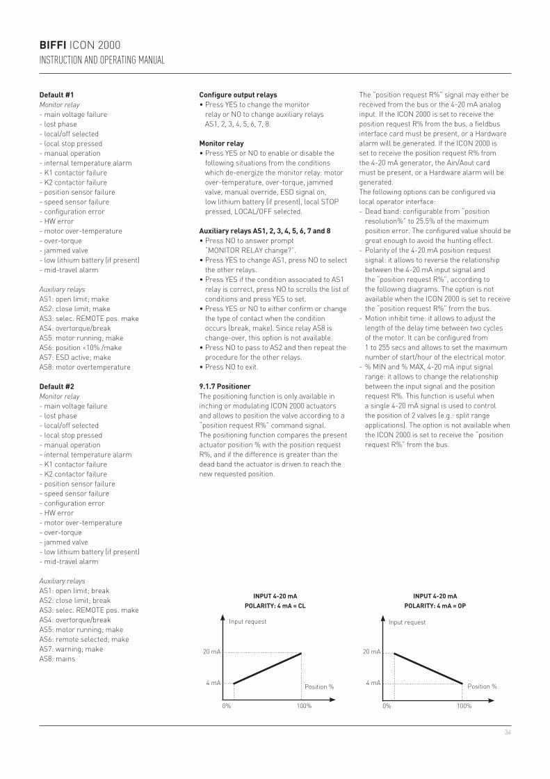
34
100% 100%0% 0%
20 mA
4 mA
20 mA
4 mA
BIFFI ICON 2000INSTRUCTION AND OPERATING MANUAL
Default #2Monitor relay- main voltage failure- lost phase- local/off selected- local stop pressed- manual operation- internal temperature alarm- K1 contactor failure- K2 contactor failure - position sensor failure- speed sensor failure- configuration error- HW error- motor over-temperature- over-torque- jammed valve- low lithium battery (if present)- mid-travel alarm
Auxiliary relaysAS1: open limit; breakAS2: close limit; breakAS3: selec. REMOTE pos. makeAS4: overtorque/breakAS5: motor running; makeAS6: remote selected; makeAS7: warning; makeAS8: mains
Configure output relays• Press YES to change the monitor
relay or NO to change auxiliary relays AS1, 2, 3, 4, 5, 6, 7, 8.
Monitor relay• Press YES or NO to enable or disable the
following situations from the conditions which de-energize the monitor relay: motor over-temperature, over-torque, jammed valve, manual override, ESD signal on, low lithium battery (if present), local STOP pressed, LOCAL/OFF selected.
Auxiliary relays AS1, 2, 3, 4, 5, 6, 7 and 8• Press NO to answer prompt
“MONITOR RELAY change?”.• Press YES to change AS1, press NO to select
the other relays.• Press YES if the condition associated to AS1
relay is correct, press NO to scrolls the list of conditions and press YES to set.
• Press YES or NO to either confirm or change the type of contact when the condition occurs (break, make). Since relay AS8 is change-over, this option is not available.
• Press NO to pass to AS2 and then repeat the procedure for the other relays.
• Press NO to exit.
9.1.7 PositionerThe positioning function is only available in inching or modulating ICON 2000 actuators and allows to position the valve according to a “position request R%” command signal.The positioning function compares the present actuator position % with the position request R%, and if the difference is greater than the dead band the actuator is driven to reach the new requested position.
The “position request R%” signal may either be received from the bus or the 4-20 mA analog input. If the ICON 2000 is set to receive the position request R% from the bus, a fieldbus interface card must be present, or a Hardware alarm will be generated. If the ICON 2000 is set to receive the position request R% from the 4-20 mA generator, the Ain/Aout card must be present, or a Hardware alarm will be generated.The following options can be configured via local operator interface:- Dead band: configurable from “position
resolution%” to 25.5% of the maximum position error. The configured value should be great enough to avoid the hunting effect.
- Polarity of the 4-20 mA position request signal: it allows to reverse the relationship between the 4-20 mA input signal and the “position request R%”, according to the following diagrams. The option is not available when the ICON 2000 is set to receive the “position request R%” from the bus.
- Motion inhibit time: it allows to adjust the length of the delay time between two cycles of the motor. It can be configured from 1 to 255 secs and allows to set the maximum number of start/hour of the electrical motor.
- % MIN and % MAX, 4-20 mA input signal range: it allows to change the relationship between the input signal and the position request R%. This function is useful when a single 4-20 mA signal is used to control the position of 2 valves (e.g.: split range applications). The option is not available when the ICON 2000 is set to receive the “position request R%” from the bus.
INPUT 4-20 mAPOLARITY: 4 mA = CL
Input request
Position %
INPUT 4-20 mAPOLARITY: 4 mA = OP
Input request
Position %
Default #1Monitor relay- main voltage failure- lost phase- local/off selected- local stop pressed- manual operation- internal temperature alarm- K1 contactor failure- K2 contactor failure - position sensor failure- speed sensor failure- configuration error- HW error- motor over-temperature- over-torque- jammed valve- low lithium battery (if present)- mid-travel alarm
Auxiliary relaysAS1: open limit; makeAS2: close limit; makeAS3: selec. REMOTE pos. makeAS4: overtorque/breakAS5: motor running; makeAS6: position <10% /makeAS7: ESD active; makeAS8: motor overtemperature
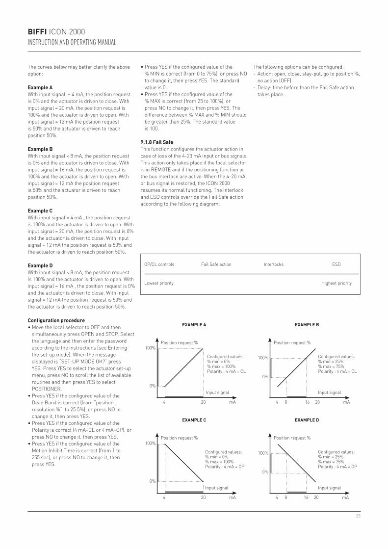
35
100%
0%
100%
0%
100%
0%
100%
0%
4 20 mA 4 8 16 20 mA
4 20 mA 4 8 16 20 mA
BIFFI ICON 2000INSTRUCTION AND OPERATING MANUAL
The curves below may better clarify the above option:
Example AWith input signal = 4 mA, the position request is 0% and the actuator is driven to close. With input signal = 20 mA, the position request is 100% and the actuator is driven to open. With input signal = 12 mA the position request is 50% and the actuator is driven to reach position 50%.
Example BWith input signal < 8 mA, the position request is 0% and the actuator is driven to close. With input signal = 16 mA, the position request is 100% and the actuator is driven to open. With input signal = 12 mA the position request is 50% and the actuator is driven to reach position 50%.
Example CWith input signal = 4 mA , the position request is 100% and the actuator is driven to open. With input signal = 20 mA, the position request is 0% and the actuator is driven to close. With input signal = 12 mA the position request is 50% and the actuator is driven to reach position 50%.
Example DWith input signal < 8 mA, the position request is 100% and the actuator is driven to open. With input signal = 16 mA , the position request is 0% and the actuator is driven to close. With input signal = 12 mA the position request is 50% and the actuator is driven to reach position 50%.
EXAMPLE A
Position request %
Input signal
Configured values:% min = 0%% max = 100%Polarity : 4 mA = CL
EXAMPLE B
Position request %
Input signal
Configured values:% min = 25%% max = 75%Polarity : 4 mA = CL
EXAMPLE C
Position request %
Input signal
Configured values:% min = 0%% max = 100%Polarity : 4 mA = OP
EXAMPLE D
Position request %
Input signal
Configured values:% min = 25%% max = 75%Polarity : 4 mA = OP
Configuration procedure• Move the local selector to OFF and then
simultaneously press OPEN and STOP. Select the language and then enter the password according to the instructions (see Entering the set-up mode). When the message displayed is “SET-UP MODE OK?” press YES. Press YES to select the actuator set-up menu, press NO to scroll the list of available routines and then press YES to select POSITIONER.
• Press YES if the configured value of the Dead Band is correct (from “position resolution %” to 25.5%), or press NO to change it, then press YES.
• Press YES if the configured value of the Polarity is correct (4 mA=CL or 4 mA=OP), or press NO to change it, then press YES.
• Press YES if the configured value of the Motion Inhibit Time is correct (from 1 to 255 sec), or press NO to change it, then press YES.
• Press YES if the configured value of the % MIN is correct (from 0 to 75%), or press NO to change it, then press YES. The standard value is 0.
• Press YES if the configured value of the % MAX is correct (from 25 to 100%), or press NO to change it, then press YES. The difference between % MAX and % MIN should be greater than 25%. The standard value is 100.
9.1.8 Fail SafeThis function configures the actuator action in case of loss of the 4-20 mA input or bus signals. This action only takes place if the local selector is in REMOTE and if the positioning function or the bus interface are active. When the 4-20 mA or bus signal is restored, the ICON 2000 resumes its normal functioning. The Interlock and ESD controls override the Fail Safe action according to the following diagram:
OP/CL controls
Lowest priority Highest priority
Fail Safe action Interlocks ESD
The following options can be configured:- Action: open, close, stay-put, go to position %,
no action (OFF).- Delay: time before than the Fail Safe action
takes place.
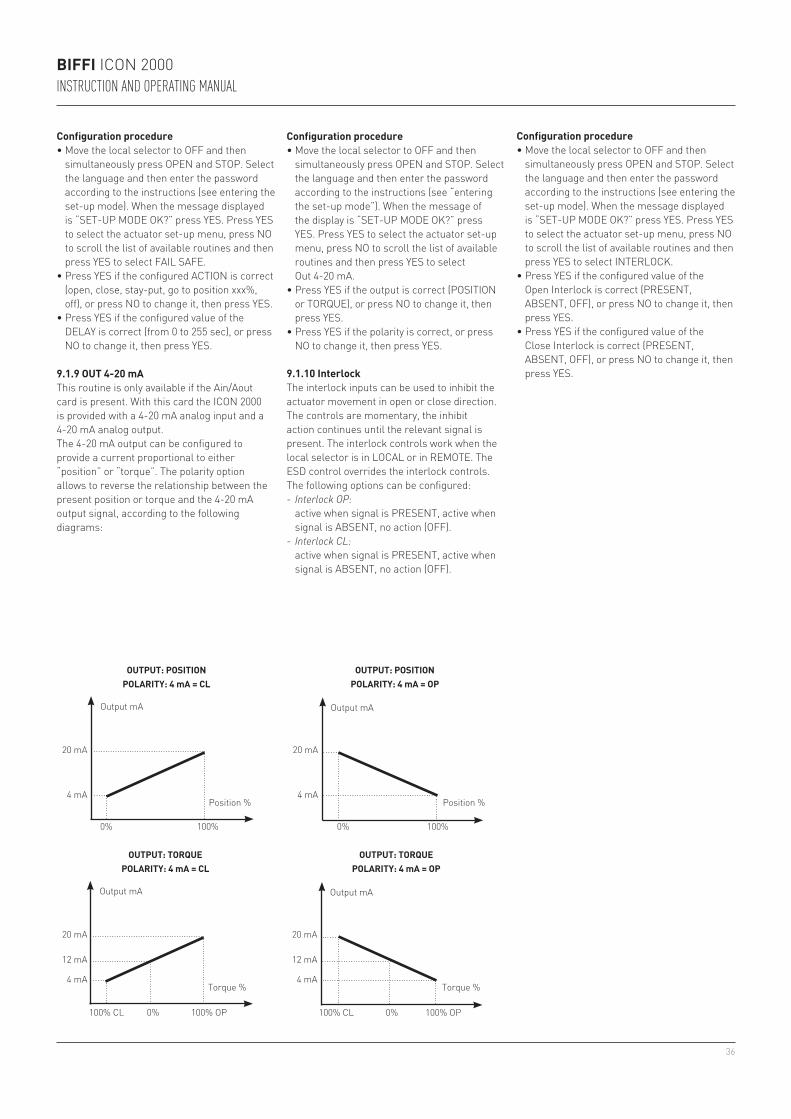
36
20 mA
4 mA
0% 100%
20 mA
4 mA
0% 100%
20 mA
12 mA 12 mA
4 mA
20 mA
4 mA
BIFFI ICON 2000INSTRUCTION AND OPERATING MANUAL
9.1.9 OUT 4-20 mAThis routine is only available if the Ain/Aout card is present. With this card the ICON 2000 is provided with a 4-20 mA analog input and a 4-20 mA analog output.The 4-20 mA output can be configured to provide a current proportional to either “position” or “torque”. The polarity option allows to reverse the relationship between the present position or torque and the 4-20 mA output signal, according to the following diagrams:
OUTPUT: POSITIONPOLARITY: 4 mA = CL
Output mA
Position %
OUTPUT: POSITIONPOLARITY: 4 mA = OP
Output mA
Position %
OUTPUT: TORQUEPOLARITY: 4 mA = CL
OUTPUT: TORQUEPOLARITY: 4 mA = OP
Output mAOutput mA
Torque % Torque %
Configuration procedure• Move the local selector to OFF and then
simultaneously press OPEN and STOP. Select the language and then enter the password according to the instructions (see “entering the set-up mode”). When the message of the display is “SET-UP MODE OK?” press YES. Press YES to select the actuator set-up menu, press NO to scroll the list of available routines and then press YES to select Out 4-20 mA.
• Press YES if the output is correct (POSITION or TORQUE), or press NO to change it, then press YES.
• Press YES if the polarity is correct, or press NO to change it, then press YES.
Configuration procedure• Move the local selector to OFF and then
simultaneously press OPEN and STOP. Select the language and then enter the password according to the instructions (see entering the set-up mode). When the message displayed is “SET-UP MODE OK?” press YES. Press YES to select the actuator set-up menu, press NO to scroll the list of available routines and then press YES to select FAIL SAFE.
• Press YES if the configured ACTION is correct (open, close, stay-put, go to position xxx%, off), or press NO to change it, then press YES.
• Press YES if the configured value of the DELAY is correct (from 0 to 255 sec), or press NO to change it, then press YES.
9.1.10 InterlockThe interlock inputs can be used to inhibit the actuator movement in open or close direction. The controls are momentary, the inhibit action continues until the relevant signal is present. The interlock controls work when the local selector is in LOCAL or in REMOTE. The ESD control overrides the interlock controls. The following options can be configured:- Interlock OP: active when signal is PRESENT, active when
signal is ABSENT, no action (OFF).- Interlock CL: active when signal is PRESENT, active when
signal is ABSENT, no action (OFF).
Configuration procedure• Move the local selector to OFF and then
simultaneously press OPEN and STOP. Select the language and then enter the password according to the instructions (see entering the set-up mode). When the message displayed is “SET-UP MODE OK?” press YES. Press YES to select the actuator set-up menu, press NO to scroll the list of available routines and then press YES to select INTERLOCK.
• Press YES if the configured value of the Open Interlock is correct (PRESENT, ABSENT, OFF), or press NO to change it, then press YES.
• Press YES if the configured value of the Close Interlock is correct (PRESENT, ABSENT, OFF), or press NO to change it, then press YES.
100% CL 0% 100% OP 100% CL 0% 100% OP
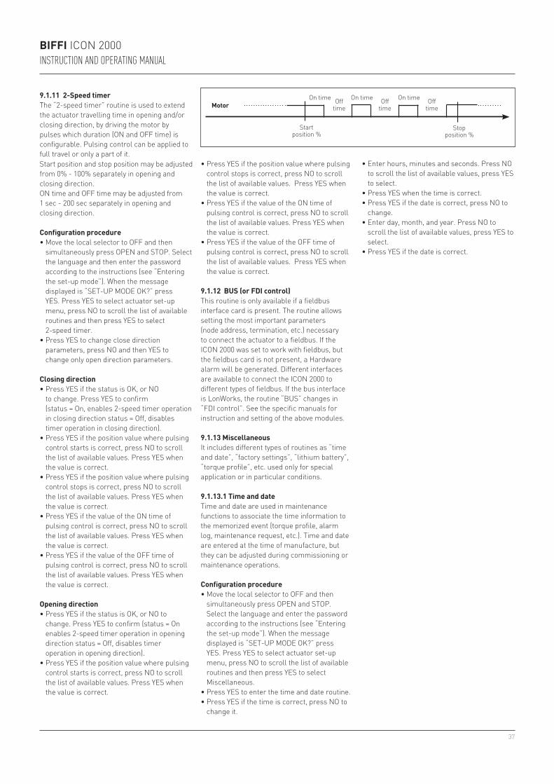
37
BIFFI ICON 2000INSTRUCTION AND OPERATING MANUAL
Motor
Startposition %
Stopposition %
On time On time On timeOfftime
Offtime
Offtime
Start position and stop position may be adjusted from 0% - 100% separately in opening and closing direction.ON time and OFF time may be adjusted from 1 sec - 200 sec separately in opening and closing direction.
Configuration procedure• Move the local selector to OFF and then
simultaneously press OPEN and STOP. Select the language and then enter the password according to the instructions (see “Entering the set-up mode”). When the message displayed is “SET-UP MODE OK?” press YES. Press YES to select actuator set-up menu, press NO to scroll the list of available routines and then press YES to select 2-speed timer.
• Press YES to change close direction parameters, press NO and then YES to change only open direction parameters.
Closing direction• Press YES if the status is OK, or NO
to change. Press YES to confirm (status = On, enables 2-speed timer operation in closing direction status = Off, disables timer operation in closing direction).
• Press YES if the position value where pulsing control starts is correct, press NO to scroll the list of available values. Press YES when the value is correct.
• Press YES if the position value where pulsing control stops is correct, press NO to scroll the list of available values. Press YES when the value is correct.
• Press YES if the value of the ON time of pulsing control is correct, press NO to scroll the list of available values. Press YES when the value is correct.
• Press YES if the value of the OFF time of pulsing control is correct, press NO to scroll the list of available values. Press YES when the value is correct.
Opening direction• Press YES if the status is OK, or NO to
change. Press YES to confirm (status = On enables 2-speed timer operation in opening direction status = Off, disables timer operation in opening direction).
• Press YES if the position value where pulsing control starts is correct, press NO to scroll the list of available values. Press YES when the value is correct.
9.1.11 2-Speed timerThe “2-speed timer” routine is used to extend the actuator travelling time in opening and/or closing direction, by driving the motor by pulses which duration (ON and OFF time) is configurable. Pulsing control can be applied to full travel or only a part of it.
• Press YES if the position value where pulsing control stops is correct, press NO to scroll the list of available values. Press YES when the value is correct.
• Press YES if the value of the ON time of pulsing control is correct, press NO to scroll the list of available values. Press YES when the value is correct.
• Press YES if the value of the OFF time of pulsing control is correct, press NO to scroll the list of available values. Press YES when the value is correct.
9.1.12 BUS (or FDI control)This routine is only available if a fieldbus interface card is present. The routine allows setting the most important parameters (node address, termination, etc.) necessary to connect the actuator to a fieldbus. If the ICON 2000 was set to work with fieldbus, but the fieldbus card is not present, a Hardware alarm will be generated. Different interfaces are available to connect the ICON 2000 to different types of fieldbus. If the bus interface is LonWorks, the routine “BUS” changes in “FDI control”. See the specific manuals for instruction and setting of the above modules.
9.1.13 MiscellaneousIt includes different types of routines as “time and date”, “factory settings”, “lithium battery”, “torque profile”, etc. used only for special application or in particular conditions.
9.1.13.1 Time and dateTime and date are used in maintenance functions to associate the time information to the memorized event (torque profile, alarm log, maintenance request, etc.). Time and date are entered at the time of manufacture, but they can be adjusted during commissioning or maintenance operations.
Configuration procedure• Move the local selector to OFF and then
simultaneously press OPEN and STOP. Select the language and enter the password according to the instructions (see “Entering the set-up mode”). When the message displayed is “SET-UP MODE OK?” press YES. Press YES to select actuator set-up menu, press NO to scroll the list of available routines and then press YES to select Miscellaneous.
• Press YES to enter the time and date routine.• Press YES if the time is correct, press NO to
change it.
• Enter hours, minutes and seconds. Press NO to scroll the list of available values, press YES to select.
• Press YES when the time is correct.• Press YES if the date is correct, press NO to
change.• Enter day, month, and year. Press NO to
scroll the list of available values, press YES to select.
• Press YES if the date is correct.
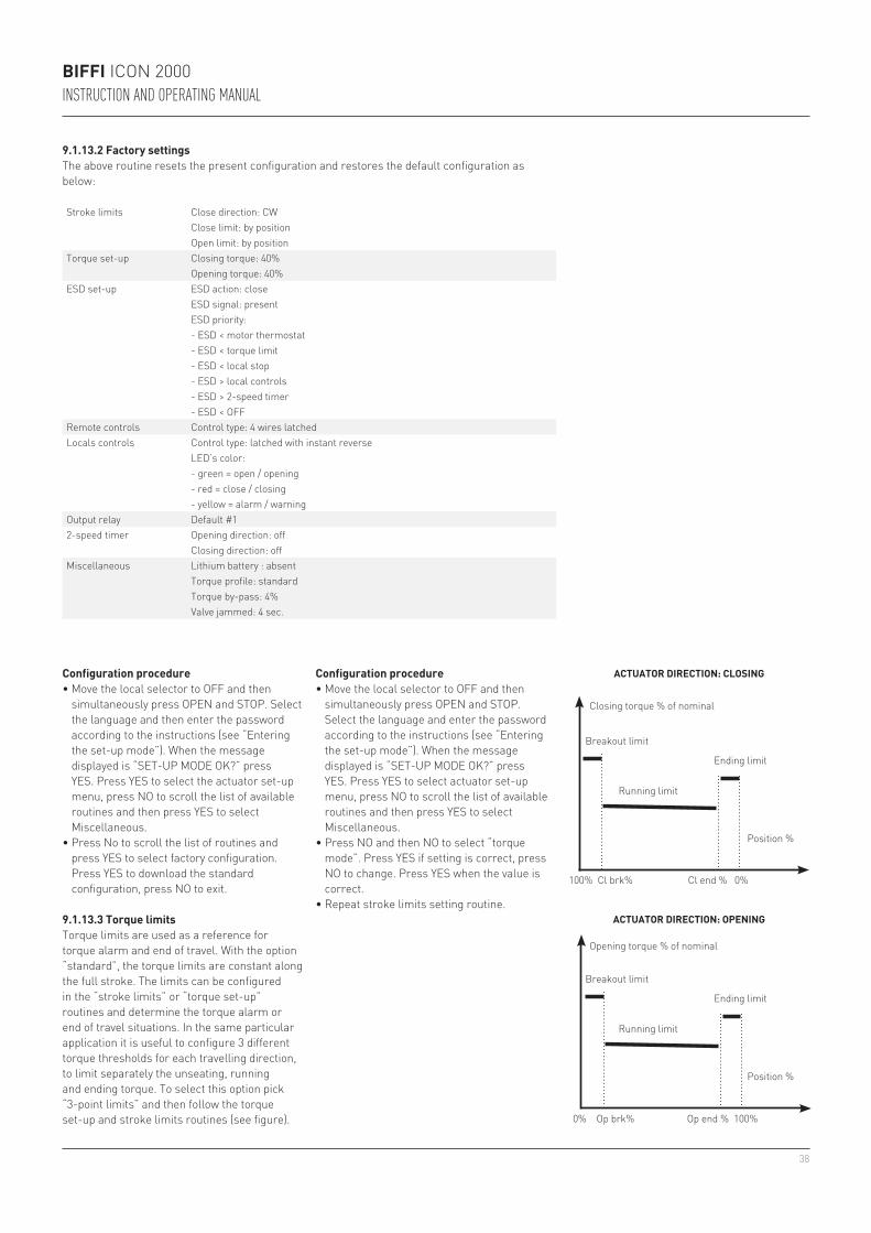
38
BIFFI ICON 2000INSTRUCTION AND OPERATING MANUAL
9.1.13.2 Factory settingsThe above routine resets the present configuration and restores the default configuration as below:
Configuration procedure• Move the local selector to OFF and then
simultaneously press OPEN and STOP. Select the language and then enter the password according to the instructions (see “Entering the set-up mode”). When the message displayed is “SET-UP MODE OK?” press YES. Press YES to select the actuator set-up menu, press NO to scroll the list of available routines and then press YES to select Miscellaneous.
• Press No to scroll the list of routines and press YES to select factory configuration. Press YES to download the standard configuration, press NO to exit.
Stroke limits Close direction: CWClose limit: by positionOpen limit: by position
Torque set-up Closing torque: 40%Opening torque: 40%
ESD set-up ESD action: closeESD signal: presentESD priority:- ESD < motor thermostat- ESD < torque limit- ESD < local stop- ESD > local controls- ESD > 2-speed timer- ESD < OFF
Remote controls Control type: 4 wires latchedLocals controls Control type: latched with instant reverse
LED’s color:- green = open / opening- red = close / closing- yellow = alarm / warning
Output relay Default #12-speed timer Opening direction: off
Closing direction: offMiscellaneous Lithium battery : absent
Torque profile: standardTorque by-pass: 4%Valve jammed: 4 sec.
9.1.13.3 Torque limitsTorque limits are used as a reference for torque alarm and end of travel. With the option “standard”, the torque limits are constant along the full stroke. The limits can be configured in the “stroke limits” or “torque set-up” routines and determine the torque alarm or end of travel situations. In the same particular application it is useful to configure 3 different torque thresholds for each travelling direction, to limit separately the unseating, running and ending torque. To select this option pick “3-point limits” and then follow the torque set-up and stroke limits routines (see figure).
ACTUATOR DIRECTION: OPENING
Opening torque % of nominal
Breakout limit
Ending limit
Position %
Running limit
ACTUATOR DIRECTION: CLOSING
Closing torque % of nominal
Breakout limit
Ending limit
Position %
Running limit
100% Cl brk% Cl end % 0%
0% Op brk% Op end % 100%
Configuration procedure• Move the local selector to OFF and then
simultaneously press OPEN and STOP. Select the language and enter the password according to the instructions (see “Entering the set-up mode”). When the message displayed is “SET-UP MODE OK?” press YES. Press YES to select actuator set-up menu, press NO to scroll the list of available routines and then press YES to select Miscellaneous.
• Press NO and then NO to select “torque mode”. Press YES if setting is correct, press NO to change. Press YES when the value is correct.
• Repeat stroke limits setting routine.
39
BIFFI ICON 2000INSTRUCTION AND OPERATING MANUAL
9.1.13.5 Torque by-pass (%)Since a high torque may be required to unseat certain valves, the torque by-pass routine masks the torque alarm when an open or close command is received and the actuator is fully open or closed. The torque by-pass is expressed in % of position and is configurable from 0% to 20%. For example, if a 10% by-pass value is set, we may have:- by-pass active in Opening: from 0% to 10%- by-pass active in Closing: from 100% to 90%To exclude torque by-pass configure 0%.
Configuration procedure• Move the local selector to OFF and then
simultaneously press OPEN and STOP. Select the language and enter the password according to the instructions (see “Entering the set-up mode”). When the message displayed is “SET-UP MODE OK?” press YES. Press YES to select actuator set-up menu, press NO to scroll the list of available routines and then press YES to select Miscellaneous.
• Press No to scroll the list of routines and press YES to select torque by pass. Press YES if the setting is correct, press NO to change. Press YES when the value is correct.
Configuration procedure• Move the local selector to OFF and then
simultaneously press OPEN and STOP. Select the language and enter the password according to the instructions (see “Entering the set-up mode”.) When the message displayed is “SET-UP MODE OK?” press YES. Press YES to select actuator set-up menu, press NO to scroll the list of available routines and then press YES to select Miscellaneous.
• Press No to scroll the list of routines and press YES to select valve jammed. Press YES if the setting is correct, press NO to change. Press YES when the value is correct.
9.2 VALVE DATA
The valve data allow identifying the valve and its function in the process. The valve manufacturer and the end user can enter the data. The following data can be entered:- Tag name (max. 28 characters)- Serial number (max. 28 characters)- Manufacturer (max. 28 characters)- Break OP torque (max. 28 characters)- Break CL torque (max. 28 characters)- Max stem thrust (max. 28 characters)- Flange type (max. 28 characters)
9.1.13.6 Valve jammed (time)The valve jammed time is used to monitor the following situations:1. The time passed after receiving an open
or close control is greater than the “valve jammed time”, but the valve position variation is smaller than 0.5%. The motor is blocked, the command is cleared and the “valve jammed” alarm indication is generated.
2. The valve is moving, but during the travel the position valve variation is smaller than 0.5% in a time equal to “valve jammed time”. The motor is blocked, the command is cleared and the “mid-travel alarm” indication is generated.
The valve jammed time is expressed in seconds and can be configured from 0 to 100 sec. Configure “0” to exclude the routine.
Configuration procedure• Move the local selector to OFF and then
simultaneously press OPEN and STOP. Select the language and enter the password according to the instructions (see “Entering the set-up mode”). When the message displayed is “SET-UP MODE OK?” press YES. Press YES to select actuator set-up menu, press NO to scroll the list of available routines and then press YES to select Miscellaneous.
• Press No to scroll the list of routines and press YES to select lithium battery. Press YES if the setting is correct, press NO to change. Press YES when the value is correct.
9.1.13.4 Lithium batteryOn request, the actuator can be provided with a lithium battery to update the remote outputs (output relays status and bus messages) in case of electrical power failure and manual override operations. The program runs the functions relevant to the battery only if the appropriate flag “lithium battery” is configured with “present”. If the battery is absent or if no updating of remote outputs is requested, the above flag should be configured with “absent”.
9.2.1 Sample configuration procedure
Tag name• Move the local selector to OFF and then
simultaneously press OPEN and STOP. Select the language and enter the password according to the instructions (see “Entering the set-up mode”). When the message displayed is “SET-UP MODE OK?” press YES. Press NO to scroll the list of available menus and then press YES to select valve data menu.
• Press NO to scroll the list of available routines and then press YES to select Tag name.
• Press YES if the 1st character of the string is correct. Press NO to scroll the list of available characters. Press YES to select the desired character.
• Enter up to 28 characters. Enter a blank character, and " " as end of string.
The configuration of all other valve data items is made in the same way, by selecting the relevant item from the list of available routines.
40
BIFFI ICON 2000INSTRUCTION AND OPERATING MANUAL
9.3.3 Set torque referenceThe set torque profile reference routine allows to transfer the last torque profile to the reference profile registers. The old reference data are lost and the new ones are used as a new reference torque profile.• Move the local selector to OFF and then
simultaneously press OPEN and STOP. Select the language and enter the password according to the instructions (see “Entering the set-up mode”). When the message displayed is “SET-UP MODE OK?” press YES. Press NO to scroll the list of available menus and then press YES to select maintenance menu.
• Press NO to scroll the list of available routines and then press YES to select Set torque reference.
• Press YES to update the torque reference data.
9.3.4 Set curve referenceThe “set curve reference” routine allows to select 1 off 100 opening and closing torque curves in the memory of the ICON 2000 and to transfer them to the torque curve reference registers. The old reference data are lost and the new ones will be the new torque curves reference (see VIEW mode, Maintenance, Torque curve, paragraph 10.4.3).
Configuration procedure• Move the local selector to OFF and then
simultaneously press OPEN and STOP. Select the language and then enter the password according to the instructions (see “Entering the set-up mode”). When the message displayed is “SET-UP MODE OK?” press YES. Press NO to scroll the list of available menus and then press YES to select maintenance menu.
• Press NO to scroll the list of available routines and then press YES to select Set curve reference.
• Press NO to scroll the list and then press YES to select the desired curves (in opening and closing).
• Press YES to update the torque curve reference.
9.3.5 Clear recent data logThe clear recent data log routine allows to clear the counters of the recent operation log. This command does not affect the content of the “general operation log”.The date of the “clear recent data log” is memorized and can be viewed in the maintenance date routine of the view menu.
9.3 MAINTENANCE
A large amount of data is stored in the actuator memory and is available for future analysis or to assist the operator in the maintenance program. The maintenance menu also includes the set password routine and the possibility to modify or start the maintenance functions.The following data are available:- set password- clear alarm log- set torque reference- set curve reference- clear recent data log- set maintenance date- set data logger
9.3.1 Set passwordThe actuator is supplied by Biffi with a default password (“0 0 0 0”). By the above routine the end user can enter a different password consisting of 4 alphanumeric characters. After entering the new password, the old one ceases to be valid. Therefore it is mandatory “NOT TO FORGET THE PASSWORD” after the default one has been modified. Forgetting the new password makes it impossible to enter the set-up menu and to configure the actuator.
Configuration procedure• Move the local selector to OFF and then
simultaneously press OPEN and STOP. Select the language and enter the password according to the instructions (see “Entering the set-up mode”). When the message displayed is “SET-UP MODE OK?” press YES. Press NO to scroll the list of available menus and then press YES to select Maintenance menu.
• Press NO to scroll the list of available routines and then press YES to select Set password.
Press YES again to select Enter new password.
• Enter the new password one digit at a time. Press YES if the digit is correct, press NO to scroll the list of available characters and then press YES to select. Enter 4 digits. When the display shows the message Password changed the old password is no longer valid.
9.3.2 Clear alarm log Clear procedure• Move the local selector to OFF and then
simultaneously press OPEN and STOP. Select the language and enter the password according to the instructions (see “Entering the set-up mode”). When the message displayed is “SET-UP MODE OK?” press YES. Press NO to scroll the list of available menus and then press YES to select the Maintenance menu.
• Press NO to scroll the list of available routines and then press YES to select clear alarm log.
• Press YES to clear alarm log.
Clearing procedure• Move the local selector to OFF and then
simultaneously press OPEN and STOP. Select the language and enter the password according to the instructions (see “Entering the set-up mode”). When the message displayed is “SET-UP MODE OK?” press YES. Press NO to scroll the list of available menus and press YES to select the maintenance menu.
• Press NO to scroll the list of available routines and then press YES to select clear recent data log.
• Press YES.• Press YES to clear or press NO to exit.
41
BIFFI ICON 2000INSTRUCTION AND OPERATING MANUAL
Last maintenance date• Press YES if the date is correct, press NO to
change it.• Enter day, month, and year. Press NO to
scroll the list of available values, press YES to select.
• Press YES if the date is correct.
Next maintenance date• Press YES if the date is correct, press NO to
change it.• Enter day, month, and year. Press NO to
scroll the list of available values, press YES to select.
• Press YES if the date is correct.
Configuration procedure• Move the local selector to OFF and then
simultaneously press OPEN and STOP. Select the language and enter the password according to the instructions (see “Entering the set-up mode”). When the message displayed is “SET-UP MODE OK?” press YES. Press NO to scroll the list of available menus and then YES to select the maintenance menu.
• Press NO to scroll the list of available routines and press YES to select maintenance date.
• Press YES to set the last maintenance date. Press NO to skip to “next maintenance date”.
9.3.6 Set maintenance dateThe maintenance date routine allows the following operations:- to set the last maintenance date- to set the next maintenance date- to set the start-up date
Start-up date• Press YES if the date is correct, press NO to
change it.• Enter day, month, and year. Press NO to
scroll the list of available values, press YES to select.
• Press YES if the date is correct.
9.3.7 Set data loggerThe “data logger” routine allows to set the data logger parameters (see VIEW mode, Maintenance, Data logger, paragraph 10.4.6).To start the data logger the following data should be set:
Logger mode recorder, event, offSampling time from 1 to 3600 secs (the sampling time is only used in recorder mode)Memory mode stop when memory is full, continuous (stop after overwriting the memory 5000 times (event)
and 10000 times (recorder/T-recorder)Start date date when the logger startsStart time time when the logger starts
Configuration procedure• Move the local selector to OFF and then
simultaneously press OPEN and STOP. Select the language and then enter the password according to the instructions (see “Entering the set-up mode”). When the message displayed is “SET-UP MODE OK?” press YES. Press NO to scroll the list of available menus and then press YES to select maintenance menu.
• Press NO to scroll the list of available routines and then press YES to select “data logger”.
• Press YES if the mode is correct. Press NO to scroll the list of modes and press YES to select the desired value .
• Press YES if the sampling time is correct. Press NO to scroll the list of times and press YES to select the desired value.
• Press YES if the memory mode is correct (stop when full or continuous). Press NO to change and press YES to select.
• Press YES if the start time is correct. Press NO to scroll the list and press YES to select the desired sampling times (hour, min, sec).
• Press YES if the start date is correct. Press NO to scroll the list and press YES to select the desired sampling times (day, month, year).
• Press YES to confirm the above settings.
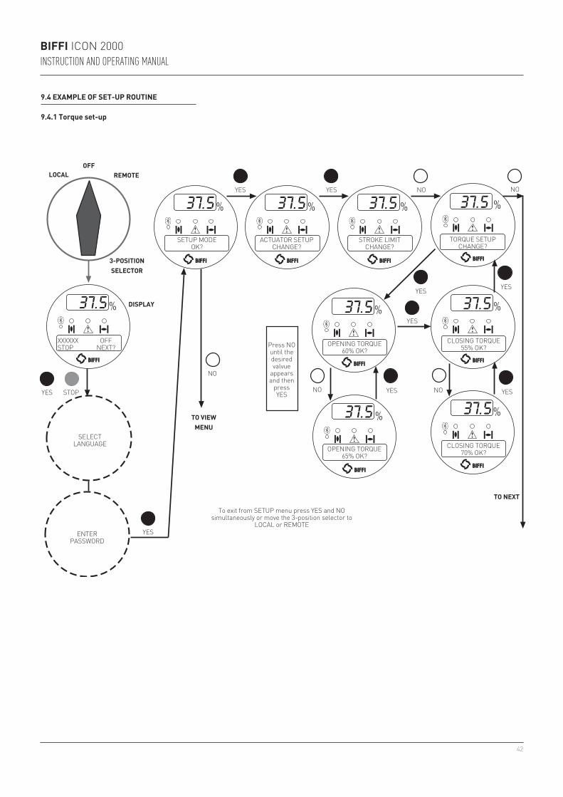
42
BIFFI ICON 2000INSTRUCTION AND OPERATING MANUAL
9.4 EXAMPLE OF SET-UP ROUTINE
9.4.1 Torque set-up
SELECTLANGUAGE
ENTERPASSWORD
SETUP MODEOK?
ACTUATOR SETUPCHANGE?
STROKE LIMITCHANGE?
TORQUE SETUPCHANGE?
CLOSING TORQUE55% OK?
CLOSING TORQUE70% OK?
OPENING TORQUE60% OK?
OPENING TORQUE65% OK?
YES
YES
YES
YES
YES
YES
YESYES
NO
NO
NO NO
NO
TO NEXT
TO VIEWMENU
To exit from SETUP menu press YES and NO simultaneously or move the 3-position selector to
LOCAL or REMOTE
Press NO until the desired valvue
appears and then
press YES
XXXXXX OFFSTOP NEXT?
DISPLAY
LOCAL REMOTE
STOPYES
OFF
3-POSITIONSELECTOR
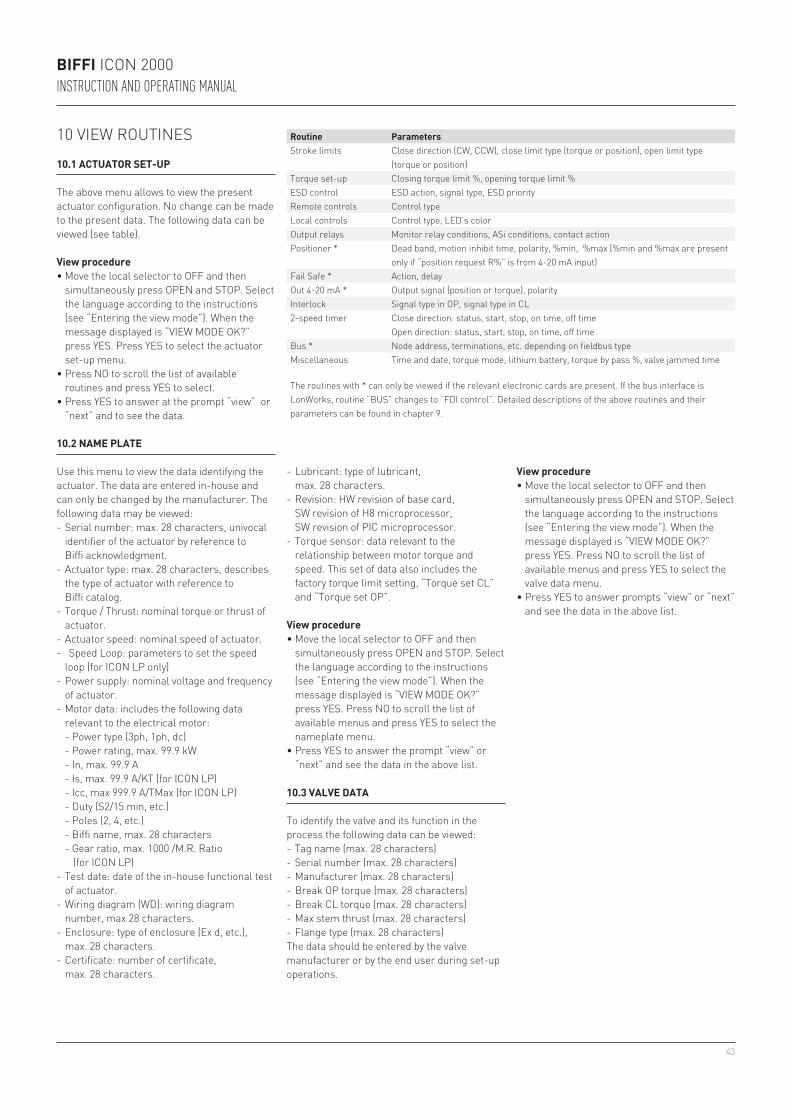
43
BIFFI ICON 2000INSTRUCTION AND OPERATING MANUAL
10 VIEW ROUTINES
10.1 ACTUATOR SET-UP
The above menu allows to view the present actuator configuration. No change can be made to the present data. The following data can be viewed (see table).
View procedure• Move the local selector to OFF and then
simultaneously press OPEN and STOP. Select the language according to the instructions (see “Entering the view mode”). When the message displayed is “VIEW MODE OK?” press YES. Press YES to select the actuator set-up menu.
• Press NO to scroll the list of available routines and press YES to select.
• Press YES to answer at the prompt “view” or “next” and to see the data.
10.2 NAME PLATE
Use this menu to view the data identifying the actuator. The data are entered in-house and can only be changed by the manufacturer. The following data may be viewed:
Routine ParametersStroke limits Close direction (CW, CCW), close limit type (torque or position), open limit type
(torque or position)Torque set-up Closing torque limit %, opening torque limit %ESD control ESD action, signal type, ESD priorityRemote controls Control typeLocal controls Control type, LED’s colorOutput relays Monitor relay conditions, ASi conditions, contact actionPositioner * Dead band, motion inhibit time, polarity, %min, %max (%min and %max are present
only if “position request R%” is from 4-20 mA input)Fail Safe * Action, delayOut 4-20 mA * Output signal (position or torque), polarityInterlock Signal type in OP, signal type in CL2-speed timer Close direction: status, start, stop, on time, off time
Open direction: status, start, stop, on time, off timeBus * Node address, terminations, etc. depending on fieldbus typeMiscellaneous Time and date, torque mode, lithium battery, torque by pass %, valve jammed time
The routines with * can only be viewed if the relevant electronic cards are present. If the bus interface is LonWorks, routine “BUS” changes to “FDI control”. Detailed descriptions of the above routines and their parameters can be found in chapter 9.
- Serial number: max. 28 characters, univocal identifier of the actuator by reference to Biffi acknowledgment.
- Actuator type: max. 28 characters, describes the type of actuator with reference to Biffi catalog.
- Torque / Thrust: nominal torque or thrust of actuator.
- Actuator speed: nominal speed of actuator.- Speed Loop: parameters to set the speed
loop (for ICON LP only)- Power supply: nominal voltage and frequency
of actuator.- Motor data: includes the following data
relevant to the electrical motor: - Power type (3ph, 1ph, dc) - Power rating, max. 99.9 kW - In, max. 99.9 A - Is, max. 99.9 A/KT (for ICON LP) - Icc, max 999.9 A/TMax (for ICON LP) - Duty (S2/15 min, etc.) - Poles (2, 4, etc.) - Biffi name, max. 28 characters - Gear ratio, max. 1000 /M.R. Ratio
(for ICON LP)- Test date: date of the in-house functional test
of actuator.- Wiring diagram (WD): wiring diagram
number, max 28 characters.- Enclosure: type of enclosure (Ex d, etc.),
max. 28 characters.- Certificate: number of certificate,
max. 28 characters.
View procedure• Move the local selector to OFF and then
simultaneously press OPEN and STOP. Select the language according to the instructions (see “Entering the view mode”). When the message displayed is “VIEW MODE OK?” press YES. Press NO to scroll the list of available menus and press YES to select the nameplate menu.
• Press YES to answer the prompt “view” or “next” and see the data in the above list.
- Lubricant: type of lubricant, max. 28 characters.
- Revision: HW revision of base card, SW revision of H8 microprocessor, SW revision of PIC microprocessor.
- Torque sensor: data relevant to the relationship between motor torque and speed. This set of data also includes the factory torque limit setting, “Torque set CL” and “Torque set OP”.
10.3 VALVE DATA
To identify the valve and its function in the process the following data can be viewed:- Tag name (max. 28 characters)- Serial number (max. 28 characters)- Manufacturer (max. 28 characters)- Break OP torque (max. 28 characters)- Break CL torque (max. 28 characters)- Max stem thrust (max. 28 characters)- Flange type (max. 28 characters)The data should be entered by the valve manufacturer or by the end user during set-up operations.
View procedure• Move the local selector to OFF and then
simultaneously press OPEN and STOP. Select the language according to the instructions (see “Entering the view mode”). When the message displayed is “VIEW MODE OK?” press YES. Press NO to scroll the list of available menus and press YES to select the valve data menu.
• Press YES to answer prompts “view” or “next” and see the data in the above list.
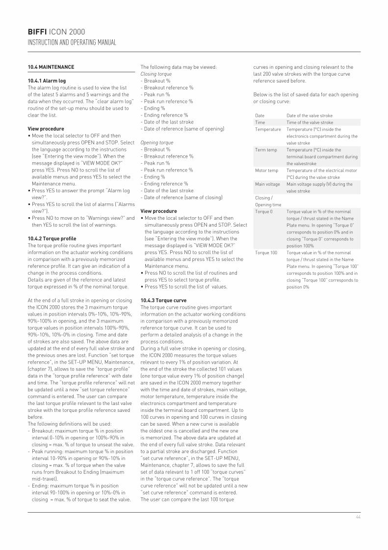
44
BIFFI ICON 2000INSTRUCTION AND OPERATING MANUAL
The following data may be viewed:Closing torque- Breakout %- Breakout reference %- Peak run %- Peak run reference %- Ending %- Ending reference %- Date of the last stroke - Date of reference (same of opening)
Opening torque- Breakout %- Breakout reference %- Peak run %- Peak run reference %- Ending %- Ending reference %- Date of the last stroke- Date of reference (same of closing)
View procedure• Move the local selector to OFF and then
simultaneously press OPEN and STOP. Select the language according to the instructions (see “Entering the view mode”). When the message displayed is “VIEW MODE OK?” press YES. Press NO to scroll the list of available menus and press YES to select the Maintenance menu.
• Press NO to scroll the list of routines and press YES to select torque profile.
• Press YES to scroll the list of values.
10.4 MAINTENANCE
10.4.1 Alarm logThe alarm log routine is used to view the list of the latest 5 alarms and 5 warnings and the data when they occurred. The “clear alarm log” routine of the set-up menu should be used to clear the list.
View procedure• Move the local selector to OFF and then
simultaneously press OPEN and STOP. Select the language according to the instructions (see “Entering the view mode”). When the message displayed is “VIEW MODE OK?” press YES. Press NO to scroll the list of available menus and press YES to select the Maintenance menu.
• Press YES to answer the prompt “Alarm log view?”.
• Press YES to scroll the list of alarms (“Alarms view?”).
• Press NO to move on to “Warnings view?” and then YES to scroll the list of warnings.
10.4.2 Torque profileThe torque profile routine gives important information on the actuator working conditions in comparison with a previously memorized reference profile. It can give an indication of a change in the process conditions. Details are given of the reference and latest torque expressed in % of the nominal torque.
At the end of a full stroke in opening or closing the ICON 2000 stores the 3 maximum torque values in position intervals 0%-10%, 10%-90%, 90%-100% in opening, and the 3 maximum torque values in position intervals 100%-90%, 90%-10%, 10%-0% in closing. Time and date of strokes are also saved. The above data are updated at the end of every full valve stroke and the previous ones are lost. Function “set torque reference”, in the SET-UP MENU, Maintenance, (chapter 7), allows to save the “torque profile” data in the “torque profile reference” with date and time. The “torque profile reference” will not be updated until a new “set torque reference” command is entered. The user can compare the last torque profile relevant to the last valve stroke with the torque profile reference saved before.The following definitions will be used: - Breakout: maximum torque % in position
interval 0-10% in opening or 100%-90% in closing = max. % of torque to unseat the valve.
- Peak running: maximum torque % in position interval 10-90% in opening or 90%-10% in closing = max. % of torque when the valve runs from Breakout to Ending (maximum mid-travel).
- Ending: maximum torque % in position interval 90-100% in opening or 10%-0% in closing = max. % of torque to seat the valve.
10.4.3 Torque curveThe torque curve routine gives important information on the actuator working conditions in comparison with a previously memorized reference torque curve. It can be used to perform a detailed analysis of a change in the process conditions.During a full valve stroke in opening or closing, the ICON 2000 measures the torque values relevant to every 1% of position variation. At the end of the stroke the collected 101 values (one torque value every 1% of position change) are saved in the ICON 2000 memory together with the time and date of strokes, main voltage, motor temperature, temperature inside the electronics compartment and temperature inside the terminal board compartment. Up to 100 curves in opening and 100 curves in closing can be saved. When a new curve is available the oldest one is cancelled and the new one is memorized. The above data are updated at the end of every full valve stroke. Data relevant to a partial stroke are discharged. Function “set curve reference”, in the SET-UP MENU, Maintenance, chapter 7, allows to save the full set of data relevant to 1 off 100 “torque curves” in the “torque curve reference”. The “torque curve reference” will not be updated until a new “set curve reference” command is entered. The user can compare the last 100 torque
Date Date of the valve strokeTime Time of the valve strokeTemperature Temperature (°C) inside the
electronics compartment during the valve stroke
Term temp Temperature (°C) inside the terminal board compartment during the valvestroke
Motor temp Temperature of the electrical motor (°C) during the valve stroke
Main voltage Main voltage supply (V) during the valve stroke
Closing / Opening timeTorque 0 Torque value in % of the nominal
torque / thrust stated in the Name Plate menu. In opening “Torque 0” corresponds to position 0% and in closing “Torque 0” corresponds to position 100%
Torque 100 Torque value in % of the nominal torque / thrust stated in the Name Plate menu. In opening “Torque 100” corresponds to position 100% and in closing “Torque 100” corresponds to position 0%
curves in opening and closing relevant to the last 200 valve strokes with the torque curve reference saved before.
Below is the list of saved data for each opening or closing curve:
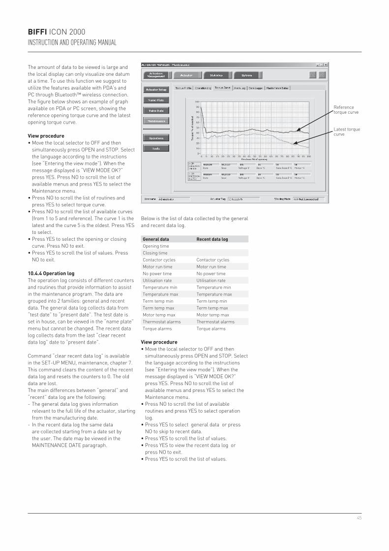
45
BIFFI ICON 2000INSTRUCTION AND OPERATING MANUAL
The amount of data to be viewed is large and the local display can only visualize one datum at a time. To use this function we suggest to utilize the features available with PDA’s and PC through Bluetooth™ wireless connection. The figure below shows an example of graph available on PDA or PC screen, showing the reference opening torque curve and the latest opening torque curve.
Reference torque curve
Latest torque curveView procedure
• Move the local selector to OFF and then simultaneously press OPEN and STOP. Select the language according to the instructions (see “Entering the view mode”). When the message displayed is “VIEW MODE OK?” press YES. Press NO to scroll the list of available menus and press YES to select the Maintenance menu.
• Press NO to scroll the list of routines and press YES to select torque curve.
• Press NO to scroll the list of available curves (from 1 to 5 and reference). The curve 1 is the latest and the curve 5 is the oldest. Press YES to select.
• Press YES to select the opening or closing curve. Press NO to exit.
• Press YES to scroll the list of values. Press NO to exit.
10.4.4 Operation logThe operation log consists of different counters and routines that provide information to assist in the maintenance program. The data are grouped into 2 families: general and recent data. The general data log collects data from “test date” to “present date”. The test date is set in house, can be viewed in the “name plate” menu but cannot be changed. The recent data log collects data from the last “clear recent data log” date to “present date”.
Command “clear recent data log” is available in the SET-UP MENU, maintenance, chapter 7. This command clears the content of the recent data log and resets the counters to 0. The old data are lost.The main differences between “general” and “recent” data log are the following:- The general data log gives information
relevant to the full life of the actuator, starting from the manufacturing date.
- In the recent data log the same data are collected starting from a date set by the user. The date may be viewed in the MAINTENANCE DATE paragraph.
View procedure• Move the local selector to OFF and then
simultaneously press OPEN and STOP. Select the language according to the instructions (see “Entering the view mode”). When the message displayed is “VIEW MODE OK?” press YES. Press NO to scroll the list of available menus and press YES to select the Maintenance menu.
• Press NO to scroll the list of available routines and press YES to select operation log.
• Press YES to select general data or press NO to skip to recent data.
• Press YES to scroll the list of values.• Press YES to view the recent data log or
press NO to exit.• Press YES to scroll the list of values.
General data Recent data logOpening timeClosing timeContactor cycles Contactor cyclesMotor run time Motor run time No power time No power time Utilisation rate Utilisation rate Temperature min Temperature minTemperature max Temperature maxTerm temp min Term temp minTerm temp max Term temp maxMotor temp max Motor temp maxThermostat alarms Thermostat alarmsTorque alarms Torque alarms
Below is the list of data collected by the general and recent data log.
46
BIFFI ICON 2000INSTRUCTION AND OPERATING MANUAL
Opening time This datum is only available in the general data log. It is updated at the end of every full valve stroke of the valve in opening direction. The data of the previous stroke are lost. It gives the time necessary to the valve to move from the close position to the open position, expressed in hours, minutes and seconds.
Closing time This datum is only available in the general data log. It is updated at the end of every full valve stroke of the valve in closing direction. The data of the previous stroke are lost. It gives the time necessary to the valve to move from the open position to the close position, expressed in hours, minutes and seconds.
Contactor cycles This number counts the cycles of contactors K1 and K2. The value indicated in the general data log is also used to generate the “max. contactor cycles” warning when the maximum allowable number of cycles of the contactor is reached (see paragraph 12.11, Diagnostic messages). If the main power is DC or single phase and in modulating actuators, the counters (general and recent) are hold to 0.
Motor run time This number counts the hours with motor energized.No power time This number counts the hours without electrical power.Utilization rate This number % is incremented every 200 full strokes of the actuator. It reaches 100%
after 20 000 full strokes.Temperature min This is the lowest temperature value (in °C) measured inside the electronics
compartment.Temperature max This is the highest temperature value (in °C) measured inside the electronics
compartment.Term temp min This is the lowest temperature value (in °C) measured inside the terminal board
enclosure.Term temp max This is the highest temperature value (in °C) measured inside the terminal board
enclosure.Motor temp max This is the highest temperature value (in °C) measured in the electrical motor.Thermostat alarms This counts the number of alarms due to the high temperature of the electrical motor
and to the tripping of the motor thermostat.Torque alarms This counts the number of alarms due to high torque in opening and closing.
10.4.5 Maintenance dateThe routine allows viewing the following dates:- Last date- Next date- Start-up date- Recent log date(see table below)
View procedure• Move the local selector to OFF and then
simultaneously press OPEN and STOP. Select the language according to the instructions (see “Entering the view mode”). When the message displayed is “VIEW MODE OK?” press YES. Press NO to scroll the list of available menus and press YES to select the Maintenance menu.
• Press NO to scroll the list of available routines and press YES to select the maintenance date routine.
• Press YES to scroll the list of dates.
Last date This is the date of the last maintenance operation. The date should be updated by the user after all maintenance operations (see paragraph 9.3).
Next date This is the date of the next scheduled actuator maintenance. When the date is reached, the ICON 2000 generates a maintenance request warning. The date should be updated by the user after all maintenance operations (see paragraph 9.3).
Start-up date This is the date of actuator start-up. During commissioning, the user should enter the start-up date (see paragraph 9.3).
Recent log date This is updated after entering command “Clear recent data log” (see paragraph 9.3). This command clears the “recent data log” counters. The content of “recent log” is updated starting from “recent log date”.
10.4.6 Data loggerThe “data logger” routine allows to collect different types of data useful in maintenance or in diagnostic programs. Since the amount of collected data is very large, the data logger can only be viewed by means of a PDA or PC. The data can be up-loaded from ICON 2000 to PDA or PC by the BluetoothTM wireless connection. The local display only allows to view the value of the configured parameters (see also SET-UP menu, Maintenance, Set data logger, paragraph 9.3.7). The following data can be viewed on the local display:- Logger mode- Sampling time- Memory mode- Date- Time
In RECORDER and T-RECORDER mode the SAMPLING TIME fixes the time interval among two sets of measures. Up to 256 sets of measures (equivalent to 256x4 samples) can be memorized. The sampling time can be configured from 1 to 3600 secs. As the memory is full, the recorder stops recording or overwrites the previous data according to the selected MEMORY MODE (“stop when full” or “continuous”). If “continuous” was selected, as a new set of measures is achieved the oldest one is cancelled and the new one becomes the latest. Up to 10000 cycles of full memory overwriting are done, then the recorder stops. In T-RECORDER mode, the recording operation is also stopped in case of OVER-TORQUE ALARM, in opening or in closing. This additional feature allows to maintain in the memory the last 256 samples and see the trend of torque, motor temperature and main voltage before the alarm. A new start of T-RECORDER clears the data stored in the memory. By a PDA or PC the recorded data can be viewed by a graph where time is on the X axis and the measured data on the Y axis.
Data logger modes:• OFF: the data logger is not active.• RECORDER mode: the ICON 2000 measures
and memorizes the following 3 data: - Main voltage supply (V) - Motor temperature (°C) - Temperature inside the compartment of
electronics (°C)• T-RECORDER mode: the ICON 2000
measures and memorizes the following 3 data:
- Torque in OP/CL - Motor temperature (°C) - Voltage
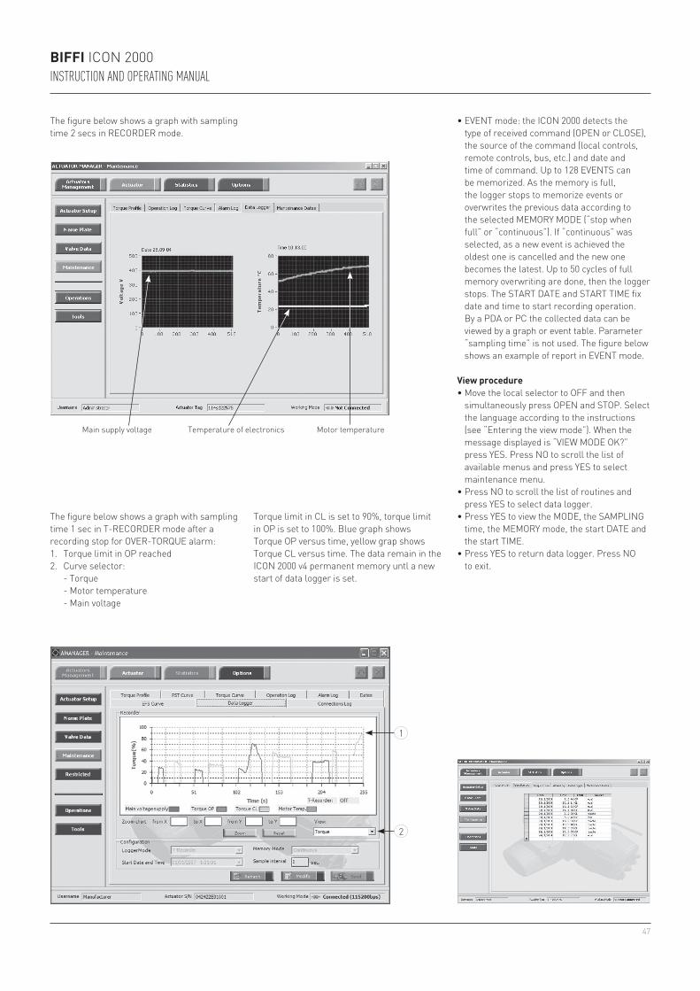
47
1
2
BIFFI ICON 2000INSTRUCTION AND OPERATING MANUAL
View procedure• Move the local selector to OFF and then
simultaneously press OPEN and STOP. Select the language according to the instructions (see “Entering the view mode”). When the message displayed is “VIEW MODE OK?” press YES. Press NO to scroll the list of available menus and press YES to select maintenance menu.
• Press NO to scroll the list of routines and press YES to select data logger.
• Press YES to view the MODE, the SAMPLING time, the MEMORY mode, the start DATE and the start TIME.
• Press YES to return data logger. Press NO to exit.
• EVENT mode: the ICON 2000 detects the type of received command (OPEN or CLOSE), the source of the command (local controls, remote controls, bus, etc.) and date and time of command. Up to 128 EVENTS can be memorized. As the memory is full, the logger stops to memorize events or overwrites the previous data according to the selected MEMORY MODE (“stop when full” or “continuous”). If “continuous” was selected, as a new event is achieved the oldest one is cancelled and the new one becomes the latest. Up to 50 cycles of full memory overwriting are done, then the logger stops. The START DATE and START TIME fix date and time to start recording operation. By a PDA or PC the collected data can be viewed by a graph or event table. Parameter “sampling time” is not used. The figure below shows an example of report in EVENT mode.
Main supply voltage Temperature of electronics Motor temperature
The figure below shows a graph with sampling time 2 secs in RECORDER mode.
The figure below shows a graph with sampling time 1 sec in T-RECORDER mode after a recording stop for OVER-TORQUE alarm:1. Torque limit in OP reached2. Curve selector: - Torque - Motor temperature - Main voltage
Torque limit in CL is set to 90%, torque limit in OP is set to 100%. Blue graph shows Torque OP versus time, yellow grap shows Torque CL versus time. The data remain in the ICON 2000 v4 permanent memory untl a new start of data logger is set.
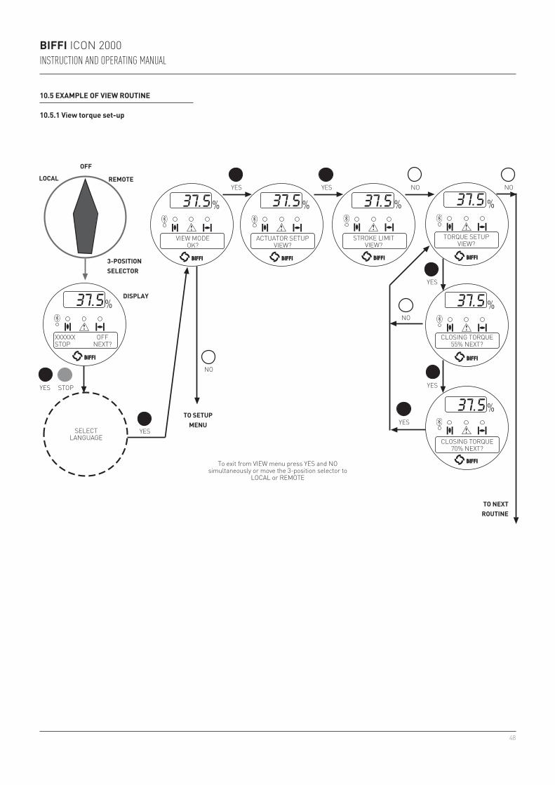
48
BIFFI ICON 2000INSTRUCTION AND OPERATING MANUAL
CLOSING TORQUE55% NEXT?
CLOSING TORQUE70% NEXT?
TORQUE SETUPVIEW?
STROKE LIMITVIEW?
ACTUATOR SETUPVIEW?
VIEW MODEOK?
YES YES
YES
YES
YES
NO
NO
NO
NO
YES
TO NEXTROUTINE
TO SETUPMENU
SELECTLANGUAGE
To exit from VIEW menu press YES and NO simultaneously or move the 3-position selector to
LOCAL or REMOTE
XXXXXX OFFSTOP NEXT?
DISPLAY
LOCAL REMOTE
STOPYES
OFF
3-POSITIONSELECTOR
10.5 EXAMPLE OF VIEW ROUTINE
10.5.1 View torque set-up
49
BIFFI ICON 2000INSTRUCTION AND OPERATING MANUAL
11 MAINTENANCE
11.1 STANDARD MAINTENANCE
Approx. every 2 years:Under normal operating conditions, the ICON 2000 is maintenance-free: no actuator maintenance is formally required, even though visual inspection for oil leakage or external visible damages is recommended every two years. When conditions are severe (frequent operation or high temperatures), inspect the oil level and oil quality more often. Replace all seals that permit oil leakage or water ingress.
The following checks will assure optimum performance:• If the stem is external, check that the valve
stem is clean and lubricated. If not, clean it and lubricate it in order to prevent damages to the threaded bush.
• Lubricate the internal components of the coupling block by means of the spherical head lubricator using suggested greases (see chapter 4, Lubrication).
• Make sure there are no oil leaks from the actuator housing. The oil level should be approx. 20 mm from the fill plug (see chapter 4, Lubrication).
• Check the external parts for possible damage and replace them immediately, if necessary. In case the window glass is broken, the complete cover must be replaced (see chapter 13, Parts list and drawings for individual item numbers).
• Repaint all areas where paint is missing. In chemically aggressive or saline environments, remove rust from surfaces and protect with a rust preventative.
11.2 SPECIAL MAINTENANCE
In case actuator failure, please refer to chapter 12, Troubleshooting for possible causes.Spare parts can be required to Biffi: please refer to the individual item number shown in chapter 13, Parts list and drawings.
IMPORTANTBefore starting any maintenance operation, make sure that the mains and all other service voltage connected to terminal board are switched-off.
WARNINGThe actuator is non-intrusive. The control compartment was sealed in dry and clean conditions and contains no site serviceable components. Do not open it unless absolutely necessary. Unauthorized access will invalidate the warranty.
WARNINGSince the control compartment contains a 3.6V lithium battery, only open it in safe area. If the actuator is located in a hazardous area a “hot work” permit must be obtained unless the actuator can be moved to a non-hazardous area.
NOTESpecial maintenance is also recommended when, during operations, the actuator generates an excessive noise.
• Check that all nuts and bolts securing the actuator to the valve are tight. If necessary, re-tighten with a dynamometric key (for tightening torque values see paragraph 3.4.3, Installation - Mounting the actuator onto the valve - Actuator fixing).
• For severe applications or if actuator operation is infrequent, perform maintenance checks more often.
• For actuators provided with lithium batteries, make sure that the display is still visible when power is off and that there is no “Battery low” warning message. If “Battery low” warning appears, replace the battery (see paragraph 11.3 Maintenance - Lithium battery change).
Always replace batteries if the actuator has been subjected to long periods without power (see chapter 12, Troubleshooting).
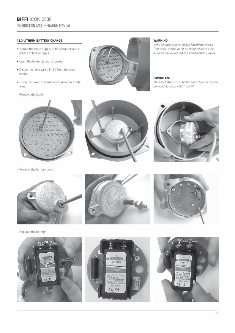
50
BIFFI ICON 2000INSTRUCTION AND OPERATING MANUAL
• Disconnect two wires (+) (-) from the main board.
• Bring the cover to a safe area. When in a safe area:
- Remove the label.
WARNINGIf the actuator is located in a hazardous area a “hot work” permit must be obtained unless the actuator can be moved to a non-hazardous area.
11.3 LITHIUM BATTERY CHANGE
• Isolate the main supply to the actuator and all other control voltages.
• Open the terminal boards cover.
- Remove the battery cover.
- Replace the battery.
IMPORTANTThe new battery must be the same type as the one provided: Lithium – SAFT LS 9V.

51
1
2
BIFFI ICON 2000INSTRUCTION AND OPERATING MANUAL
12 TROUBLESHOOTING
The ICON 2000 actuator has passed the functional test performed by Biffi Quality Assurance personnel.
WARNINGThe actuator is non-intrusive. The control compartment was sealed in dry and clean conditions and contains no site serviceable components. Do not open it unless absolutely necessary. Unauthorized access will invalidate the warranty.
WARNINGSince the control compartment contains a 3.6V lithium battery, only open it in safe area. If the actuator is located in a hazardous area, a “hot work” permit must be obtained unless the actuator can be moved to a non-hazardous area.
If the actuator does not work, before troubleshooting make sure that:• the numeric display indicates xx %;• the local selector is not in OFF;• the main supply voltage is the same as stated
in the name plate menu;• you move the local selector to OFF and check
that the alphanumeric display shows one of the following messages:
- “normal off” - “alarm off” - “warning off” - “ESD ON off” - “INT off”
If the above checks are satisfactory try to locate the fault using the diagnostic facilities.
12.1 THE ELECTRONICS DO NOT SWITCH ON WHEN POWERED
• Check that the value of the main voltage on terminals L1, L2, L3 is correct.
• Remove the cover of the compartment where the electronic cards are located.
• Check the fuse mounted on the power card. Replace it if burnt.
• If the fuse is OK, check the wires between terminals L1, L2, L3 and connector M1 of the power card. If it is correct, replace the power card.
12.2 DC OUTPUT VOLTAGE NOT AVAILABLE AT THE TERMINALS
• Switch the main power supply off and disconnect all wires from terminals B1-B2 and C1.
• Switch the main power supply on and check if the voltage on the terminals B1-B2 and C1 is between 23 and 27 V DC.
• If the voltage is correct check the external wiring and the electrical load. It should not exceed 4 W.
• If the voltage is not correct replace the power card.
1. Power card2. Fuse
12.3 THE ACTUATOR DOES NOT WORK FROM REMOTE CONTROLS
• Move the 3-position selector to LOCAL and check that the actuator works from local controls.
• Move the local selector to REMOTE. If the ESD signal is active, the alphanumeric display indicates “ESD On”. Check the signal on terminals C3 and C4 and adjust the ESD configuration. If the alphanumeric display indicates “INT”, an interlock control is present. Check the signal on terminals B3, B4 and B5, and adjust Interlocks configuration.
• Check that: - the wiring to terminals B1-B2 and C1 is
correct; - there is no short-circuit between wires; - the electrical load does not exceed 4 W; - the value is in the range 20-120 V AC
50/60 Hz or 20-125 V DC, if external voltage supply is used.
12.4 THE MOTOR IS VERY HOT AND DOES NOT START
• Check that no alarm other than motor overheating is present.
• Wait until the motor cools down and the normally closed contact of the thermal switch automatically resets before trying to operate the actuator again.
• Check that the number of operations per hour and their duration is suitable for the actuator service (see the name-plate menu).
• Check that the valve operating torque is within the range of the unit’s designed operating torque.
• Always check the causes of abnormal operation.
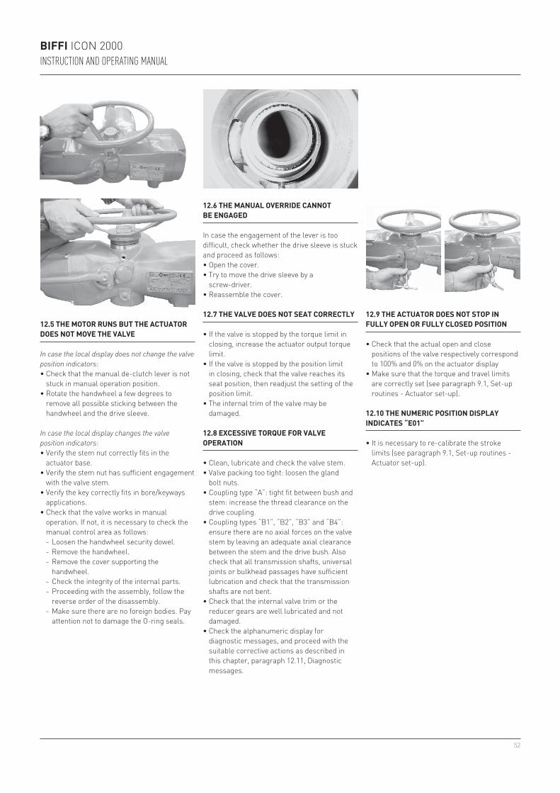
52
BIFFI ICON 2000INSTRUCTION AND OPERATING MANUAL
12.6 THE MANUAL OVERRIDE CANNOT BE ENGAGED
In case the engagement of the lever is too difficult, check whether the drive sleeve is stuck and proceed as follows:• Open the cover.• Try to move the drive sleeve by a
screw-driver.• Reassemble the cover.
12.7 THE VALVE DOES NOT SEAT CORRECTLY
• If the valve is stopped by the torque limit in closing, increase the actuator output torque limit.
• If the valve is stopped by the position limit in closing, check that the valve reaches its seat position, then readjust the setting of the position limit.
• The internal trim of the valve may be damaged.
12.8 EXCESSIVE TORQUE FOR VALVE OPERATION
• Clean, lubricate and check the valve stem.• Valve packing too tight: loosen the gland
bolt nuts.• Coupling type “A”: tight fit between bush and
stem: increase the thread clearance on the drive coupling.
• Coupling types “B1”, “B2”, “B3” and “B4”: ensure there are no axial forces on the valve stem by leaving an adequate axial clearance between the stem and the drive bush. Also check that all transmission shafts, universal joints or bulkhead passages have sufficient lubrication and check that the transmission shafts are not bent.
• Check that the internal valve trim or the reducer gears are well lubricated and not damaged.
• Check the alphanumeric display for diagnostic messages, and proceed with the suitable corrective actions as described in this chapter, paragraph 12.11, Diagnostic messages.
12.9 THE ACTUATOR DOES NOT STOP IN FULLY OPEN OR FULLY CLOSED POSITION
• Check that the actual open and close positions of the valve respectively correspond to 100% and 0% on the actuator display
• Make sure that the torque and travel limits are correctly set (see paragraph 9.1, Set-up routines - Actuator set-up).
12.10 THE NUMERIC POSITION DISPLAY INDICATES “E01”
• It is necessary to re-calibrate the stroke limits (see paragraph 9.1, Set-up routines - Actuator set-up).
12.5 THE MOTOR RUNS BUT THE ACTUATOR DOES NOT MOVE THE VALVE
In case the local display does not change the valve position indicators:• Check that the manual de-clutch lever is not
stuck in manual operation position.• Rotate the handwheel a few degrees to
remove all possible sticking between the handwheel and the drive sleeve.
In case the local display changes the valve position indicators:• Verify the stem nut correctly fits in the
actuator base.• Verify the stem nut has sufficient engagement
with the valve stem.• Verify the key correctly fits in bore/keyways
applications.• Check that the valve works in manual
operation. If not, it is necessary to check the manual control area as follows:
- Loosen the handwheel security dowel. - Remove the handwheel. - Remove the cover supporting the
handwheel. - Check the integrity of the internal parts. - Proceeding with the assembly, follow the
reverse order of the disassembly. - Make sure there are no foreign bodies. Pay
attention not to damage the O-ring seals.
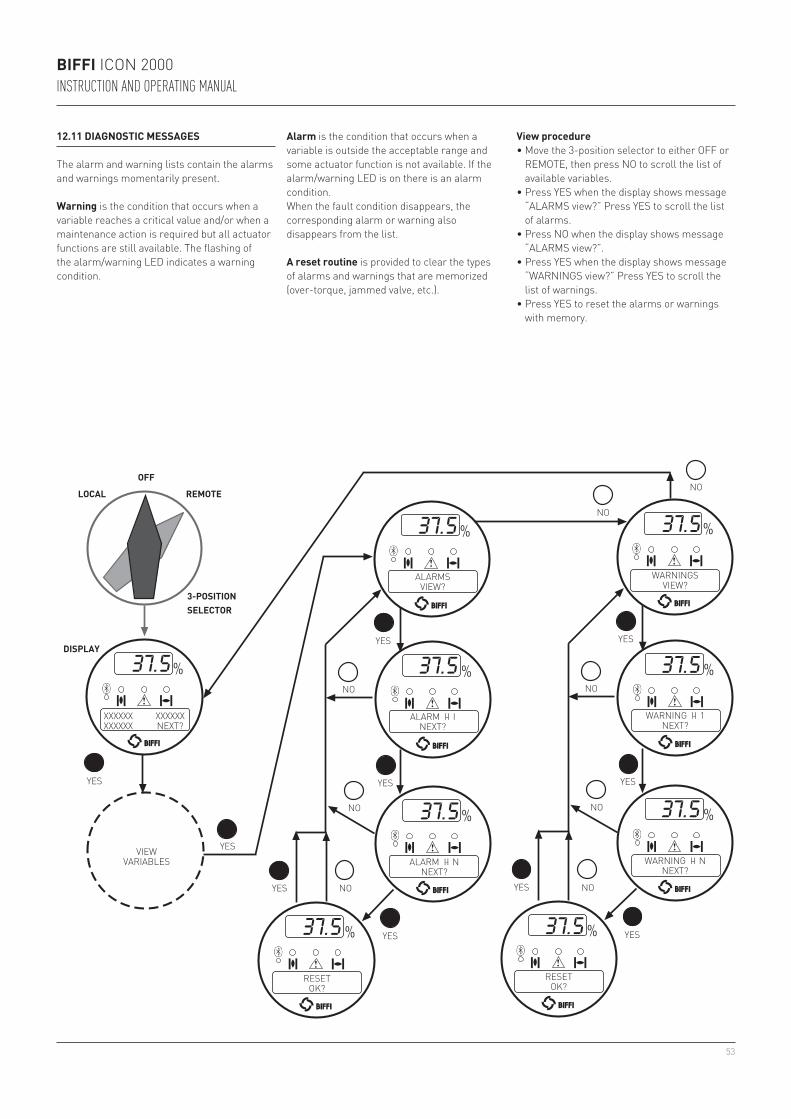
53
BIFFI ICON 2000INSTRUCTION AND OPERATING MANUAL
12.11 DIAGNOSTIC MESSAGES
The alarm and warning lists contain the alarms and warnings momentarily present.
Warning is the condition that occurs when a variable reaches a critical value and/or when a maintenance action is required but all actuator functions are still available. The flashing of the alarm/warning LED indicates a warning condition.
View procedure• Move the 3-position selector to either OFF or
REMOTE, then press NO to scroll the list of available variables.
• Press YES when the display shows message “ALARMS view?” Press YES to scroll the list of alarms.
• Press NO when the display shows message “ALARMS view?”.
• Press YES when the display shows message “WARNINGS view?” Press YES to scroll the list of warnings.
• Press YES to reset the alarms or warnings with memory.
XXXXXX XXXXXXXXXXXX NEXT?
ALARMSVIEW?
ALARM I-I INEXT?
ALARM I-I NNEXT?
RESETOK?
RESETOK?
WARNING I-I NNEXT?
WARNING I-I 1NEXT?
WARNINGSVIEW?
DISPLAY
3-POSITIONSELECTOR
LOCAL REMOTE
YES
YES YES
YES
YES
YESYES
YES
YES
YES
NO
NO
NO
NO
NO
NO
NO
NO
OFF
VIEWVARIABLES
Alarm is the condition that occurs when a variable is outside the acceptable range and some actuator function is not available. If the alarm/warning LED is on there is an alarm condition.When the fault condition disappears, the corresponding alarm or warning also disappears from the list.
A reset routine is provided to clear the types of alarms and warnings that are memorized (over-torque, jammed valve, etc.).
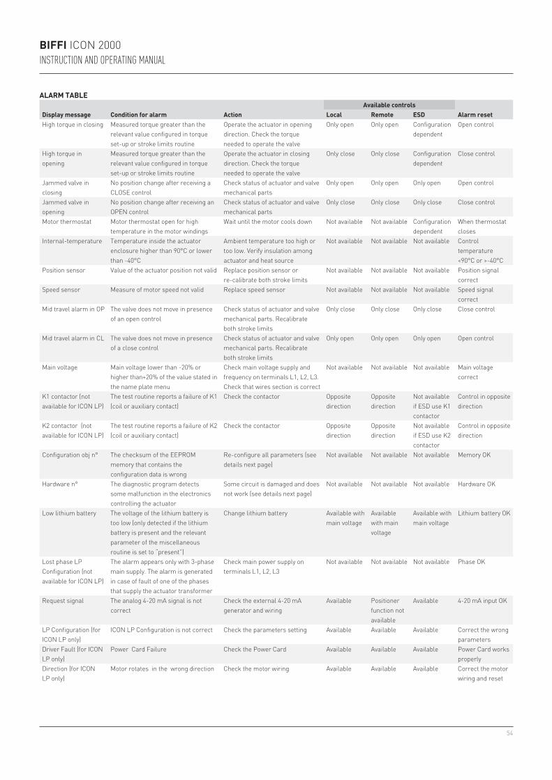
54
BIFFI ICON 2000INSTRUCTION AND OPERATING MANUAL
ALARM TABLE
Display message Condition for alarm ActionAvailable controls
Alarm resetLocal Remote ESDHigh torque in closing Measured torque greater than the
relevant value configured in torque set-up or stroke limits routine
Operate the actuator in opening direction. Check the torque needed to operate the valve
Only open Only open Configuration dependent
Open control
High torque in opening
Measured torque greater than the relevant value configured in torque set-up or stroke limits routine
Operate the actuator in closing direction. Check the torque needed to operate the valve
Only close Only close Configuration dependent
Close control
Jammed valve in closing
No position change after receiving a CLOSE control
Check status of actuator and valve mechanical parts
Only open Only open Only open Open control
Jammed valve in opening
No position change after receiving an OPEN control
Check status of actuator and valve mechanical parts
Only close Only close Only close Close control
Motor thermostat Motor thermostat open for high temperature in the motor windings
Wait until the motor cools down Not available Not available Configuration dependent
When thermostat closes
Internal-temperature Temperature inside the actuator enclosure higher than 90°C or lower than -40°C
Ambient temperature too high or too low. Verify insulation among actuator and heat source
Not available Not available Not available Control temperature <90°C or >-40°C
Position sensor Value of the actuator position not valid Replace position sensor or re-calibrate both stroke limits
Not available Not available Not available Position signal correct
Speed sensor Measure of motor speed not valid Replace speed sensor Not available Not available Not available Speed signal correct
Mid travel alarm in OP The valve does not move in presence of an open control
Check status of actuator and valve mechanical parts. Recalibrate both stroke limits
Only close Only close Only close Close control
Mid travel alarm in CL The valve does not move in presence of a close control
Check status of actuator and valve mechanical parts. Recalibrate both stroke limits
Only open Only open Only open Open control
Main voltage Main voltage lower than -20% or higher than+20% of the value stated in the name plate menu
Check main voltage supply and frequency on terminals L1, L2, L3. Check that wires section is correct
Not available Not available Not available Main voltage correct
K1 contactor (not available for ICON LP)
The test routine reports a failure of K1 (coil or auxiliary contact)
Check the contactor Opposite direction
Opposite direction
Not available if ESD use K1 contactor
Control in opposite direction
K2 contactor (not available for ICON LP)
The test routine reports a failure of K2 (coil or auxiliary contact)
Check the contactor Opposite direction
Opposite direction
Not available if ESD use K2 contactor
Control in opposite direction
Configuration obj n° The checksum of the EEPROM memory that contains the configuration data is wrong
Re-configure all parameters (see details next page)
Not available Not available Not available Memory OK
Hardware n° The diagnostic program detects some malfunction in the electronics controlling the actuator
Some circuit is damaged and does not work (see details next page)
Not available Not available Not available Hardware OK
Low lithium battery The voltage of the lithium battery is too low (only detected if the lithium battery is present and the relevant parameter of the miscellaneous routine is set to “present”)
Change lithium battery Available with main voltage
Available with main voltage
Available with main voltage
Lithium battery OK
Lost phase LP Configuration (not available for ICON LP)
The alarm appears only with 3-phase main supply. The alarm is generated in case of fault of one of the phases that supply the actuator transformer
Check main power supply on terminals L1, L2, L3
Not available Not available Not available Phase OK
Request signal The analog 4-20 mA signal is not correct
Check the external 4-20 mA generator and wiring
Available Positioner function not available
Available 4-20 mA input OK
LP Configuration (for ICON LP only)
ICON LP Configuration is not correct Check the parameters setting Available Available Available Correct the wrong parameters
Driver Fault (for ICON LP only)
Power Card Failure Check the Power Card Available Available Available Power Card works properly
Direction (for ICON LP only)
Motor rotates in the wrong direction Check the motor wiring Available Available Available Correct the motor wiring and reset
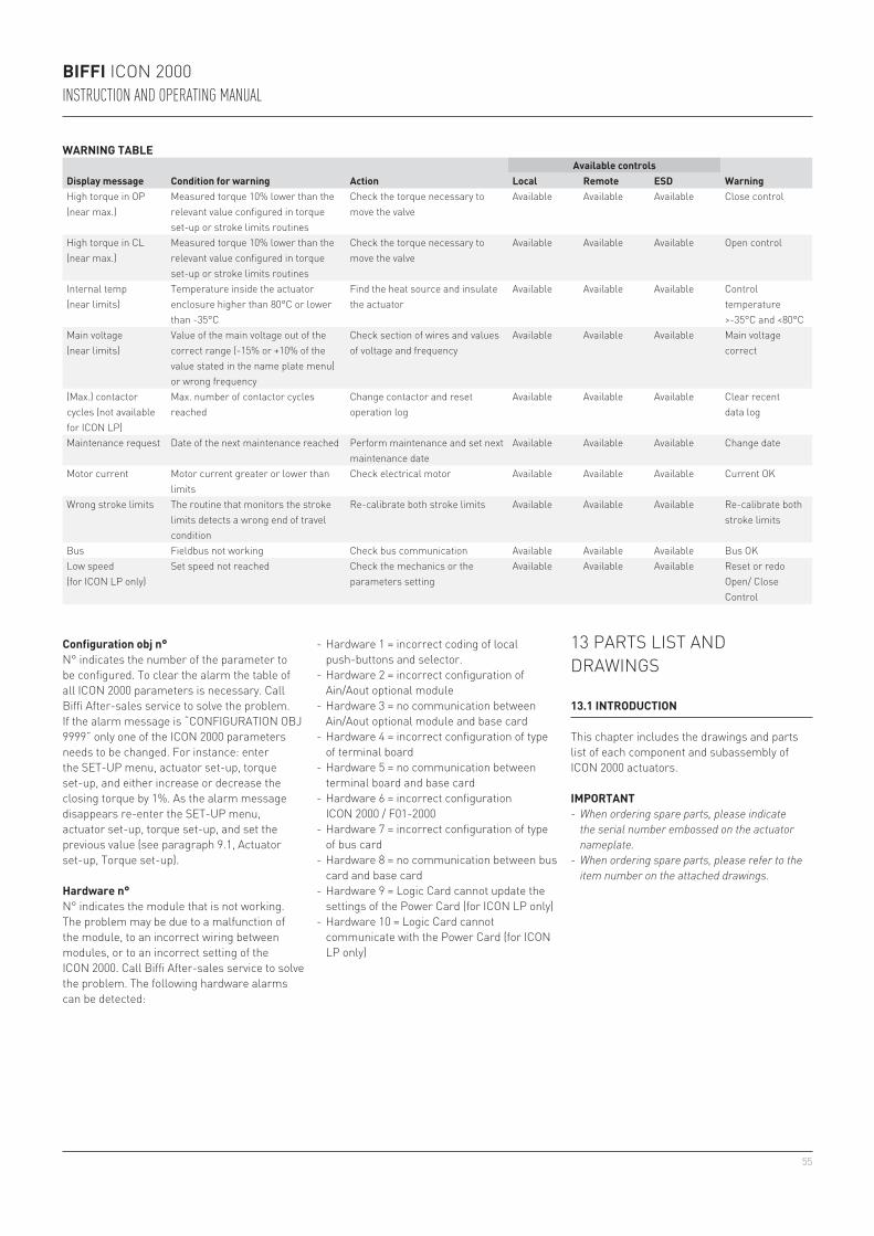
55
BIFFI ICON 2000INSTRUCTION AND OPERATING MANUAL
13 PARTS LIST AND DRAWINGS
13.1 INTRODUCTION
This chapter includes the drawings and parts list of each component and subassembly of ICON 2000 actuators.
IMPORTANT- When ordering spare parts, please indicate
the serial number embossed on the actuator nameplate.
- When ordering spare parts, please refer to the item number on the attached drawings.
Configuration obj n°N° indicates the number of the parameter to be configured. To clear the alarm the table of all ICON 2000 parameters is necessary. Call Biffi After-sales service to solve the problem.If the alarm message is “CONFIGURATION OBJ 9999” only one of the ICON 2000 parameters needs to be changed. For instance: enter the SET-UP menu, actuator set-up, torque set-up, and either increase or decrease the closing torque by 1%. As the alarm message disappears re-enter the SET-UP menu, actuator set-up, torque set-up, and set the previous value (see paragraph 9.1, Actuator set-up, Torque set-up).
Hardware n°N° indicates the module that is not working. The problem may be due to a malfunction of the module, to an incorrect wiring between modules, or to an incorrect setting of the ICON 2000. Call Biffi After-sales service to solve the problem. The following hardware alarms can be detected:
- Hardware 1 = incorrect coding of local push-buttons and selector.
- Hardware 2 = incorrect configuration of Ain/Aout optional module
- Hardware 3 = no communication between Ain/Aout optional module and base card
- Hardware 4 = incorrect configuration of type of terminal board
- Hardware 5 = no communication between terminal board and base card
- Hardware 6 = incorrect configuration ICON 2000 / F01-2000
- Hardware 7 = incorrect configuration of type of bus card
- Hardware 8 = no communication between bus card and base card
- Hardware 9 = Logic Card cannot update the settings of the Power Card (for ICON LP only)
- Hardware 10 = Logic Card cannot communicate with the Power Card (for ICON LP only)
WARNING TABLE
Display message Condition for warning ActionAvailable controls
WarningLocal Remote ESDHigh torque in OP (near max.)
Measured torque 10% lower than the relevant value configured in torque set-up or stroke limits routines
Check the torque necessary to move the valve
Available Available Available Close control
High torque in CL (near max.)
Measured torque 10% lower than the relevant value configured in torque set-up or stroke limits routines
Check the torque necessary to move the valve
Available Available Available Open control
Internal temp (near limits)
Temperature inside the actuator enclosure higher than 80°C or lower than -35°C
Find the heat source and insulate the actuator
Available Available Available Control temperature >-35°C and <80°C
Main voltage (near limits)
Value of the main voltage out of the correct range (-15% or +10% of the value stated in the name plate menu) or wrong frequency
Check section of wires and values of voltage and frequency
Available Available Available Main voltage correct
(Max.) contactor cycles (not available for ICON LP)
Max. number of contactor cycles reached
Change contactor and reset operation log
Available Available Available Clear recent data log
Maintenance request Date of the next maintenance reached Perform maintenance and set next maintenance date
Available Available Available Change date
Motor current Motor current greater or lower than limits
Check electrical motor Available Available Available Current OK
Wrong stroke limits The routine that monitors the stroke limits detects a wrong end of travel condition
Re-calibrate both stroke limits Available Available Available Re-calibrate both stroke limits
Bus Fieldbus not working Check bus communication Available Available Available Bus OKLow speed (for ICON LP only)
Set speed not reached Check the mechanics or the parameters setting
Available Available Available Reset or redo Open/ Close Control
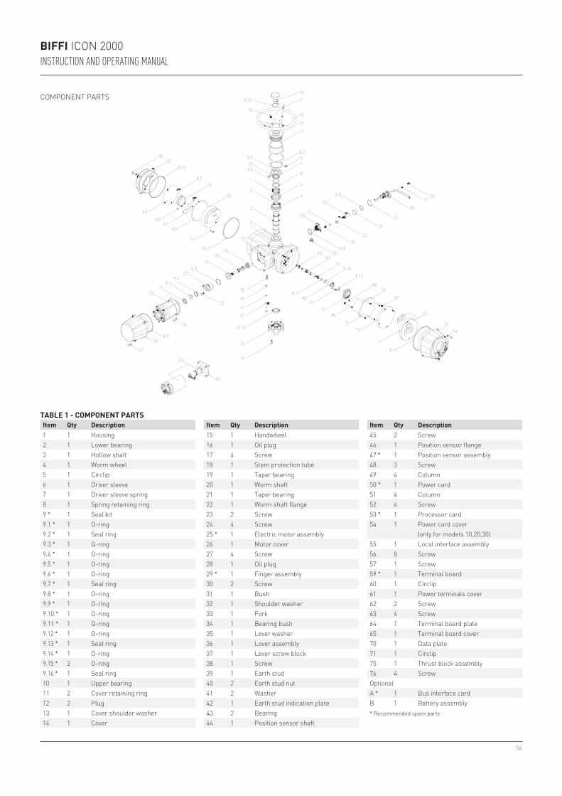
56
BIFFI ICON 2000INSTRUCTION AND OPERATING MANUAL
COMPONENT PARTS
1 1 Housing2 1 Lower bearing3 1 Hollow shaft4 1 Worm wheel5 1 Circlip6 1 Driver sleeve7 1 Driver sleeve spring8 1 Spring retaining ring9 * 1 Seal kit9.1 * 1 O-ring9.2 * 1 Seal ring9.3 * 1 Q-ring9.4 * 1 O-ring9.5 * 1 O-ring9.6 * 1 O-ring9.7 * 1 Seal ring9.8 * 1 O-ring9.9 * 1 O-ring9.10 * 1 O-ring9.11 * 1 Q-ring9.12 * 1 O-ring9.13 * 1 Seal ring9.14 * 1 O-ring9.15 * 2 O-ring9.16 * 1 Seal ring10 1 Upper bearing11 2 Cover retaining ring12 2 Plug13 1 Cover shoulder washer14 1 Cover
15 1 Handwheel16 1 Oil plug17 4 Screw18 1 Stem protection tube19 1 Taper bearing20 1 Worm shaft 21 1 Taper bearing 22 1 Worm shaft flange23 2 Screw24 4 Screw25 * 1 Electric motor assembly26 1 Motor cover27 4 Screw28 1 Oil plug29 * 1 Finger assembly30 2 Screw31 1 Bush32 1 Shoulder washer33 1 Fork34 1 Bearing bush35 1 Lever washer36 1 Lever assembly37 1 Lever screw block38 1 Screw39 1 Earth stud 40 2 Earth stud nut 41 2 Washer 42 1 Earth stud indication plate43 2 Bearing44 1 Position sensor shaft
45 2 Screw46 1 Position sensor flange47 * 1 Position sensor assembly48 3 Screw49 4 Column50 * 1 Power card51 4 Column52 4 Screw53 * 1 Processor card54 1 Power card cover
(only for models 10,20,30)55 1 Local interface assembly56 8 Screw57 1 Screw59 * 1 Terminal board60 1 Circlip61 1 Power terminals cover62 2 Screw63 4 Screw64 1 Terminal board plate65 1 Terminal board cover70 1 Data plate71 1 Circlip75 1 Thrust block assembly76 4 ScrewOptionalA * 1 Bus interface cardB 1 Battery assembly* Recommended spare parts
TABLE 1 - COMPONENT PARTSItem Qty Description Item Qty Description Item Qty Description
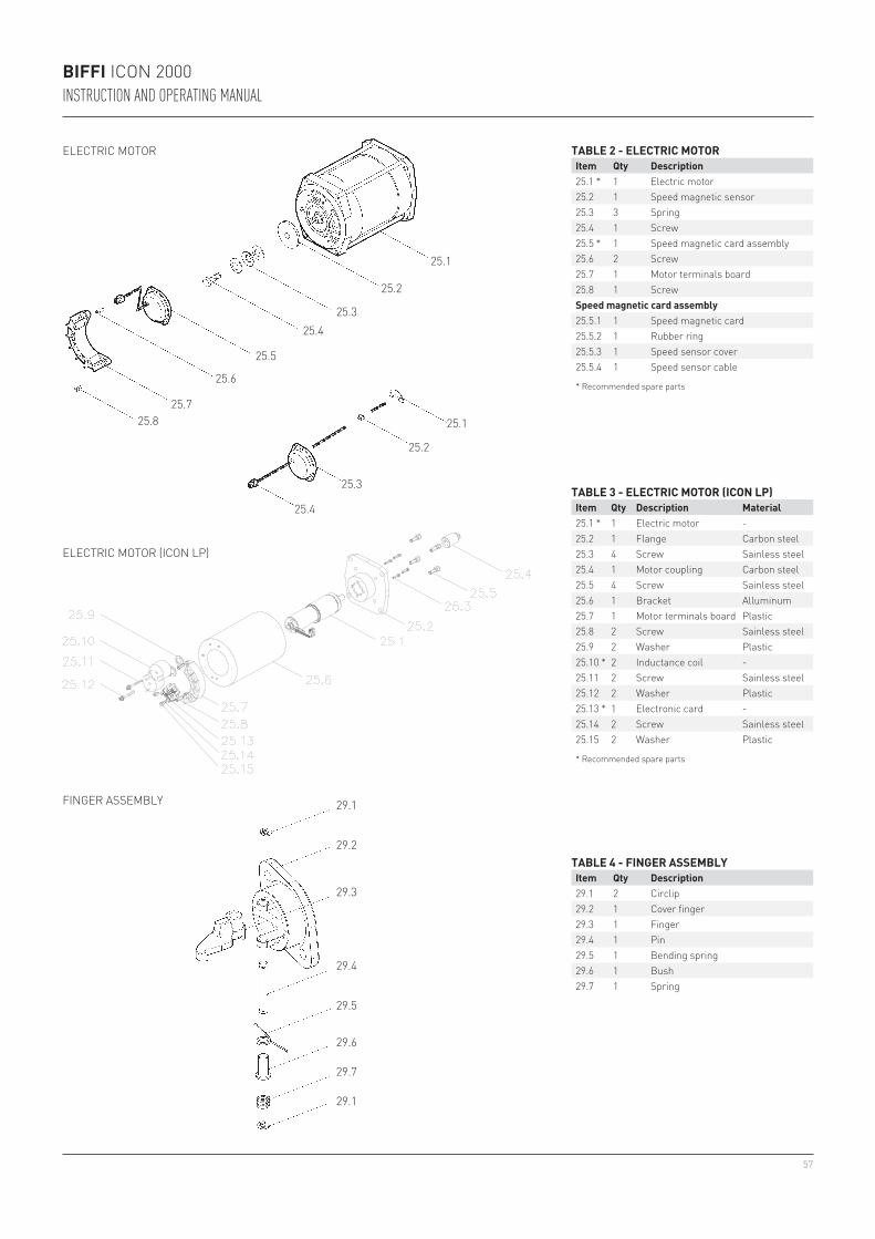
57
25.1
25.2
25.325.4
25.5
25.6
25.725.8 25.1
25.2
25.3
25.4
29.1
29.2
29.3
29.4
29.5
29.6
29.7
29.1
BIFFI ICON 2000INSTRUCTION AND OPERATING MANUAL
ELECTRIC MOTOR
ELECTRIC MOTOR (ICON LP)
FINGER ASSEMBLY
TABLE 2 - ELECTRIC MOTORItem Qty Description25.1 * 1 Electric motor25.2 1 Speed magnetic sensor25.3 3 Spring25.4 1 Screw25.5 * 1 Speed magnetic card assembly25.6 2 Screw25.7 1 Motor terminals board25.8 1 ScrewSpeed magnetic card assembly25.5.1 1 Speed magnetic card25.5.2 1 Rubber ring25.5.3 1 Speed sensor cover25.5.4 1 Speed sensor cable
* Recommended spare parts
TABLE 3 - ELECTRIC MOTOR (ICON LP)Item Qty Description Material25.1 * 1 Electric motor -25.2 1 Flange Carbon steel25.3 4 Screw Sainless steel25.4 1 Motor coupling Carbon steel25.5 4 Screw Sainless steel25.6 1 Bracket Alluminum25.7 1 Motor terminals board Plastic25.8 2 Screw Sainless steel25.9 2 Washer Plastic25.10 * 2 Inductance coil -25.11 2 Screw Sainless steel25.12 2 Washer Plastic25.13 * 1 Electronic card -25.14 2 Screw Sainless steel25.15 2 Washer Plastic
* Recommended spare parts
TABLE 4 - FINGER ASSEMBLYItem Qty Description29.1 2 Circlip29.2 1 Cover finger29.3 1 Finger29.4 1 Pin29.5 1 Bending spring29.6 1 Bush29.7 1 Spring
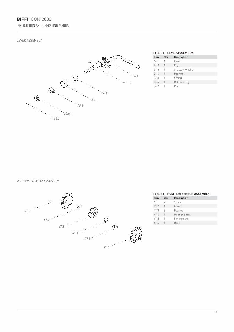
58
36.1
36.2
36.3
36.4
36.5
36.636.7
47.4
47.5
47.6
47.3
47.2
47.1
BIFFI ICON 2000INSTRUCTION AND OPERATING MANUAL
LEVER ASSEMBLY
POSITION SENSOR ASSEMBLY
TABLE 5 - LEVER ASSEMBLYItem Qty Description36.1 1 Lever36.2 1 Key36.3 1 Shoulder washer36.4 1 Bearing36.5 1 Spring36.6 1 Retainer ring36.7 1 Pin
TABLE 6 - POSITION SENSOR ASSEMBLYItem Qty Description47.1 2 Screw47.2 1 Cover47.3 2 Bearing47.4 1 Magnetic disk47.5 1 Sensor card47.6 1 Base
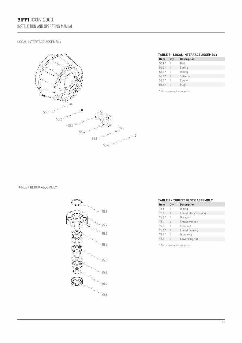
59
55.4
55.5
55.6
55.3
55.2
55.1
75.1
75.2
75.3
75.4
75.5
75.6
75.7
75.8
BIFFI ICON 2000INSTRUCTION AND OPERATING MANUAL
LOCAL INTERFACE ASSEMBLY
THRUST BLOCK ASSEMBLY
TABLE 7 - LOCAL INTERFACE ASSEMBLYItem Qty Description55.1 * 1 Ball55.2 * 1 Spring55.3 * 1 O-ring55.4 * 1 Selector55.5 * 1 Screw55.6 * 1 Plug
* Recommended spare parts
TABLE 8 - THRUST BLOCK ASSEMBLYItem Qty Description75.1 1 O-ring75.2 1 Thrust block housing75.3 * 1 Greaser75.4 4 Thrust washer75.5 1 Stem nut75.6 * 2 Thrust bearing75.7 * 1 Quad ring75.8 1 Lower ring nut
* Recommended spare parts
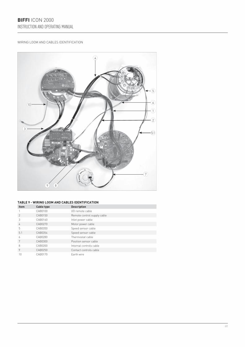
60
10
3
2
7
89
1
6
5
4
5.1
BIFFI ICON 2000INSTRUCTION AND OPERATING MANUAL
WIRING LOOM AND CABLES IDENTIFICATION
TABLE 9 - WIRING LOOM AND CABLES IDENTIFICATIONItem Cable type Description1 CAB0100 I/O remote cable2 CAB0150 Remote control supply cable3 CAB0160 Inlet power cable4 CAB0270 Motor power cable5 CAB0350 Speed sensor cable5.1 CAB0354 Speed sensor cable6 CAB0280 Thermostat cable7 CAB0300 Position sensor cable8 CAB0200 Internal controls cable9 CAB0250 Contact controls cable10 CAB0170 Earth wire

61
BIFFI ICON 2000 / ICON 2000 ADADDENDUM A TO INSTRUCTION AND OPERATING MANUAL
WARNINGIt is assumed that the installation, setting, commissioning, maintenance and repair works are carried out by qualified personnel and checked by responsible specialists.
14 SAFETY INSTRUCTIONS
14.1 GENERAL
This Addendum A is an integration to ICON 2000 main IOM VCIOM-01232 to prescribe the safety instructions applicable to all the electric actuators Series ICON 2000 / ICON 2000 AD either as a base unit either when they are equipped with an optional extension [A] for additional entry mounted on the control compartment or when they are equipped with an optional extension [B] with additional entries or with an optional extension [C] with optional electronic card both mounted on the terminal board compartment, as identified by the pictures here below, when they are installed in Hazardous Areas as defined by the IEC/EN 60079-10-1 IEC/EN 60079-10-2.Under the same conditions, the optional extensions [A], [B] or [C], can be mounted on a base unit ICON 2000 / ICON 2000 AD already installed on field.
Both the base unit ICON 2000 / ICON 2000 AD and optional extension are designed in accordance with the applicable international rules and specifications but in any case the following regulation must be observed:- The general installation and safety
regulations.- The proper use of personal protective devices
(glasses, clothing, gloves).- The proper use of tools, lifting and transport
equipment.
14.2 IDENTIFICATION OF MAIN PARTS
Base unit
Base unit with extension [A]
Base unit with extensions [B] or [C]
(c Ex de IIB+H2 T4 Gb / c Ex tb IIIC T135°C Db IP66/68 c Ex de ia IIB+H2 T4 Gb / c Ex tb IIIC T135°C Db IP66/68)
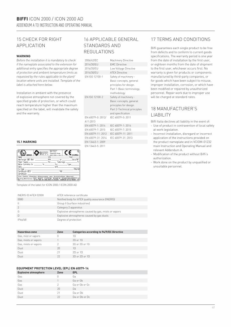
62
BIFFI ICON 2000 / ICON 2000 ADADDENDUM A TO INSTRUCTION AND OPERATING MANUAL
15.1 MARKING
INERIS 03 ATEX 0200X ATEX reference certificate 0080 Notified body for ATEX quality assurance (INERIS) II Group II (surface industries)2 Category 2 apparatus G Explosive atmospheres caused by gas, mists or vaporsD Explosive atmospheres caused by gas dusts IP66/68 Degree of protection
15 CHECK FOR RIGHT APPLICATION
WARNINGBefore the installation it is mandatory to check if the nameplate associated to the extension for additional entry specifies the appropriate degree of protection and ambient temperature limits as requested by the rules applicable to the plant/location where units are installed. Template of the label is attached here below.
Installation in ambient with the presence of explosive atmosphere not covered by the specified grade of protection, or which could reach temperature higher than the maximum specified on the label, will invalidate the safety and the warranty.
Template of the label for ICON 2000 / ICON 2000 AD
Hazardous zone Zone Categories according to 94/9/EC DirectiveGas, mist or vapors 0 1GGas, mists or vapors 1 2G or 1GGas, mists or vapors 2 3G or 2G or 1GDust 20 1DDust 21 2D or 1DDust 22 3D or 2D or 1D
16 APPLICABLE GENERAL STANDARDS AND REGULATIONS
EQUIPMENT PROTECTION LEVEL (EPL) EN 60079-14Explosive atmosphere Zone EPLGas 0 GaGas 1 Ga or GbGas 2 Ga or Gb or GcDust 20 DaDust 21 Da or DbDust 22 Da or Db or Dc
2006/42/EC Machinery Directive2014/30/EU EMC Directive2014/35/EU Low Voltage Directive2014/30/EU ATEX DirectiveEN ISO 12100-1 Safety of machinery -
Basic concepts, general principles for design. Part 1-Basic terminology, methodology
EN ISO 12100-2 Safety of machinery - Basic concepts, general principles for design. Part 2-Technical principles and specification
EN 60079-0: 2012/A11:2013
IEC 60079-0: 2011
EN 60079-1: 2014 IEC 60079-1: 2014EN 60079-7: 2015 IEC 60079-7: 2015EN 60079-11: 2012 IEC 60079-11: 2011EN 60079-31: 2014 IEC 60079-31: 2013EN 13463-1: 2009EN 13463-5: 2011
17 TERMS AND CONDITIONS
Biffi guarantees each single product to be free from defects and to conform to current goods specifications. The warranty period is one year from the date of installation by the first user, or eighteen months from the date of shipment to the first user, whichever occurs first. No warranty is given for products or components manufactured by third-party companies, or for goods which have been subject to misuse, improper installation, corrosion, or which have been modified or repaired by unauthorized personnel. Repair work due to improper use will be charged at standard rates.
18 MANUFACTURER’S LIABILITYBiffi Italia declines all liability in the event of:- Use of product in contravention of local safety
at work legislation.- Incorrect installation, disregard or incorrect
application of the instructions provided on the product nameplate and in VCIOM-01232 main Instruction and Operating Manual and relevant Addendum A.
- Modification of the product without Biffi’s authorization.
- Work done on the product by unqualified or unsuitable personnel.
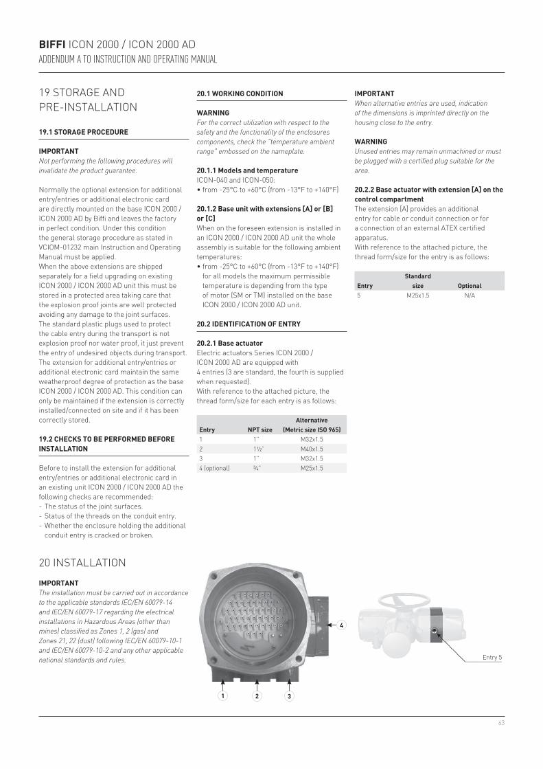
63
4
1 2 3
BIFFI ICON 2000 / ICON 2000 ADADDENDUM A TO INSTRUCTION AND OPERATING MANUAL
19 STORAGE AND PRE-INSTALLATION
19.1 STORAGE PROCEDURE
IMPORTANTNot performing the following procedures will invalidate the product guarantee.
Normally the optional extension for additional entry/entries or additional electronic card are directly mounted on the base ICON 2000 / ICON 2000 AD by Biffi and leaves the factory in perfect condition. Under this condition the general storage procedure as stated in VCIOM-01232 main Instruction and Operating Manual must be applied.When the above extensions are shipped separately for a field upgrading on existing ICON 2000 / ICON 2000 AD unit this must be stored in a protected area taking care that the explosion proof joints are well protected avoiding any damage to the joint surfaces.The standard plastic plugs used to protect the cable entry during the transport is not explosion proof nor water proof, it just prevent the entry of undesired objects during transport.The extension for additional entry/entries or additional electronic card maintain the same weatherproof degree of protection as the base ICON 2000 / ICON 2000 AD. This condition can only be maintained if the extension is correctly installed/connected on site and if it has been correctly stored.
19.2 CHECKS TO BE PERFORMED BEFORE INSTALLATION
Before to install the extension for additional entry/entries or additional electronic card in an existing unit ICON 2000 / ICON 2000 AD the following checks are recommended:- The status of the joint surfaces.- Status of the threads on the conduit entry.- Whether the enclosure holding the additional
conduit entry is cracked or broken.
20 INSTALLATION
IMPORTANTThe installation must be carried out in accordance to the applicable standards IEC/EN 60079-14 and IEC/EN 60079-17 regarding the electrical installations in Hazardous Areas (other than mines) classified as Zones 1, 2 (gas) and Zones 21, 22 (dust) following IEC/EN 60079-10-1 and IEC/EN 60079-10-2 and any other applicable national standards and rules.
IMPORTANTWhen alternative entries are used, indication of the dimensions is imprinted directly on the housing close to the entry.
WARNINGUnused entries may remain unmachined or must be plugged with a certified plug suitable for the area.
Entry NPT sizeAlternative
(Metric size ISO 965)1 1” M32x1.52 1½” M40x1.53 1” M32x1.54 (optional) ¾” M25x1.5
20.1 WORKING CONDITION
WARNINGFor the correct utilization with respect to the safety and the functionality of the enclosures components, check the "temperature ambient range" embossed on the nameplate.
20.1.1 Models and temperatureICON-040 and ICON-050:• from -25°C to +60°C (from -13°F to +140°F)
20.1.2 Base unit with extensions [A] or [B] or [C]When on the foreseen extension is installed in an ICON 2000 / ICON 2000 AD unit the whole assembly is suitable for the following ambient temperatures:• from -25°C to +60°C (from -13°F to +140°F)
for all models the maximum permissible temperature is depending from the type of motor (SM or TM) installed on the base ICON 2000 / ICON 2000 AD unit.
20.2.2 Base actuator with extension [A] on the control compartmentThe extension [A] provides an additional entry for cable or conduit connection or for a connection of an external ATEX certified apparatus.With reference to the attached picture, the thread form/size for the entry is as follows:
Entry 5
EntryStandard
size Optional5 M25x1.5 N/A
20.2 IDENTIFICATION OF ENTRY
20.2.1 Base actuatorElectric actuators Series ICON 2000 / ICON 2000 AD are equipped with4 entries (3 are standard, the fourth is supplied when requested).With reference to the attached picture, the thread form/size for each entry is as follows:
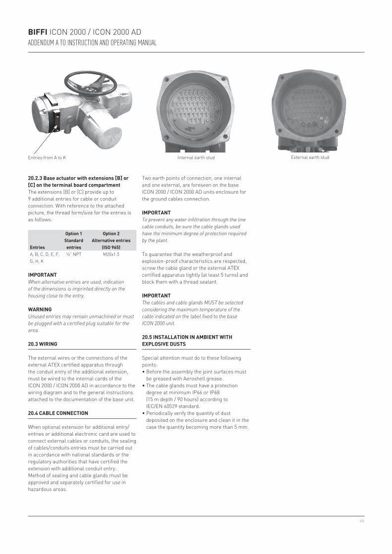
64
BIFFI ICON 2000 / ICON 2000 ADADDENDUM A TO INSTRUCTION AND OPERATING MANUAL
20.2.3 Base actuator with extensions [B] or [C] on the terminal board compartmentThe extensions [B] or [C] provide up to 9 additional entries for cable or conduit connection. With reference to the attached picture, the thread form/size for the entries is as follows:
Entries from A to K
Entries
Option 1 Standard entries
Option 2 Alternative entries
(ISO 965)A, B, C, D, E, F, G, H, K
½” NPT M20x1.5
IMPORTANTWhen alternative entries are used, indication of the dimensions is imprinted directly on the housing close to the entry.
WARNINGUnused entries may remain unmachined or must be plugged with a certified plug suitable for the area.
20.3 WIRING
The external wires or the connections of the external ATEX certified apparatus through the conduit entry of the additional extension, must be wired to the internal cards of the ICON 2000 / ICON 2000 AD in accordance to the wiring diagram and to the general instructions attached to the documentation of the base unit.
20.4 CABLE CONNECTION
When optional extension for additional entry/entries or additional electronic card are used to connect external cables or conduits, the sealing of cables/conduits entries must be carried out in accordance with national standards or the regulatory authorities that have certified the extension with additional conduit entry.Method of sealing and cable glands must be approved and separately certified for use in hazardous areas.
Two earth points of connection, one internal and one external, are foreseen on the base ICON 2000 / ICON 2000 AD units enclosure for the ground cables connection.
Internal earth stud External earth stud
IMPORTANTTo prevent any water infiltration through the line cable conduits, be sure the cable glands used have the minimum degree of protection required by the plant.
To guarantee that the weatherproof and explosion-proof characteristics are respected, screw the cable gland or the external ATEX certified apparatus tightly (at least 5 turns) and block them with a thread sealant.
IMPORTANTThe cables and cable glands MUST be selected considering the maximum temperature of the cable indicated on the label fixed to the base ICON 2000 unit.
20.5 INSTALLATION IN AMBIENT WITH EXPLOSIVE DUSTS
Special attention must do to these following points: • Before the assembly the joint surfaces must
be greased with Aeroshell grease.• The cable glands must have a protection
degree at minimum IP66 or IP68 (15 m depth / 90 hours) according to IEC/EN 60529 standard.
• Periodically verify the quantity of dust deposited on the enclosure and clean it in the case the quantity becoming more than 5 mm.
65
BIFFI ICON 2000 / ICON 2000 ADADDENDUM A TO INSTRUCTION AND OPERATING MANUAL
21.3 REPAIRS
When needed, repair must only be carried out with manufacturer’s original spare parts.
WARNINGThe values of gaps of explosion-proof joints are lower than the maximum specified on tables of IEC/EN 60079-1 Standard and the values of widths of the explosion-proof joints are superior to the values specified on tables of the Standard IEC/EN 60079-1. In case the maintenance should require the replacement of any component which forms part of an explosion-proof joint, only an original spare provided by Biffi MUST be used. Direct repair or reconstruction of the above components are not permitted without the Biffi permission. Not performing this procedure will invalidate the product safety and contractual guarantee.
Original spare parts must be required to the manufacturer: to ensure that right spare is provided, serial number printed on the ICON 2000 unit enclosure label must be specified when spares are ordered.
21.2 DISMANTLING AND REASSEMBLING
WARNINGIn case the screws of the cover must been replaced, a SS AISI 316 Class A4 Grade 70, must be used with minimum yield strength of 450 N/mm2.
In case a dismantling and subsequent reassembling of the explosion-proof enclosure is required, be careful to maintain all parts in their original condition.So the following procedure must be followed:• Do not damage the explosion-proof mating
surfaces on the housing and on the electrical enclosure cover.
21 MAINTENANCE
WARNINGIn case the units equipped with extension for additional entry or additional entries, already installed in HAZARDOUS AREAS, need maintenance and/or any repair work, this must be carried out by personnel specifically qualified and fully trained for works in HAZARDOUS AREAS.
21.1 PERIODIC INSPECTIONS
• Inspect the general conditions of the ICON 2000 / ICON 2000 AD plus the possible optional additional extension at regular intervals: recommended frequency of inspection is one time every two years but this frequency could be changed depending on the installation and working conditions: any crack on the surface, broken window or loose bolts must be reported for repair.
• Keep the external surfaces of the unit clean: if the unit is installed in a dusty environment the specification stated in IEC/EN 60079-14 to be followed ensuring in particular that the dust layer does not exceed 5 mm.
• Check the condition of cable connection and mounting bolts: any loose connection must be amended.
• Reinstall all the screws that go with the dismantled parts and block after spreading them with a film of molybdenum-based grease. This will keep screws from sticking and make maintenance future operations easier.
• In case the screws need to be changed it is mandatory to assure that the new screws are of the same dimension and same material as the original ones as stated in this manual, or of a better quality.
• Replace the weatherproof seals that may have been removed i.e: O-rings for the cover.
• In particular, be sure the joint surfaces of all enclosures are spread with a film of Aeroshell grease.
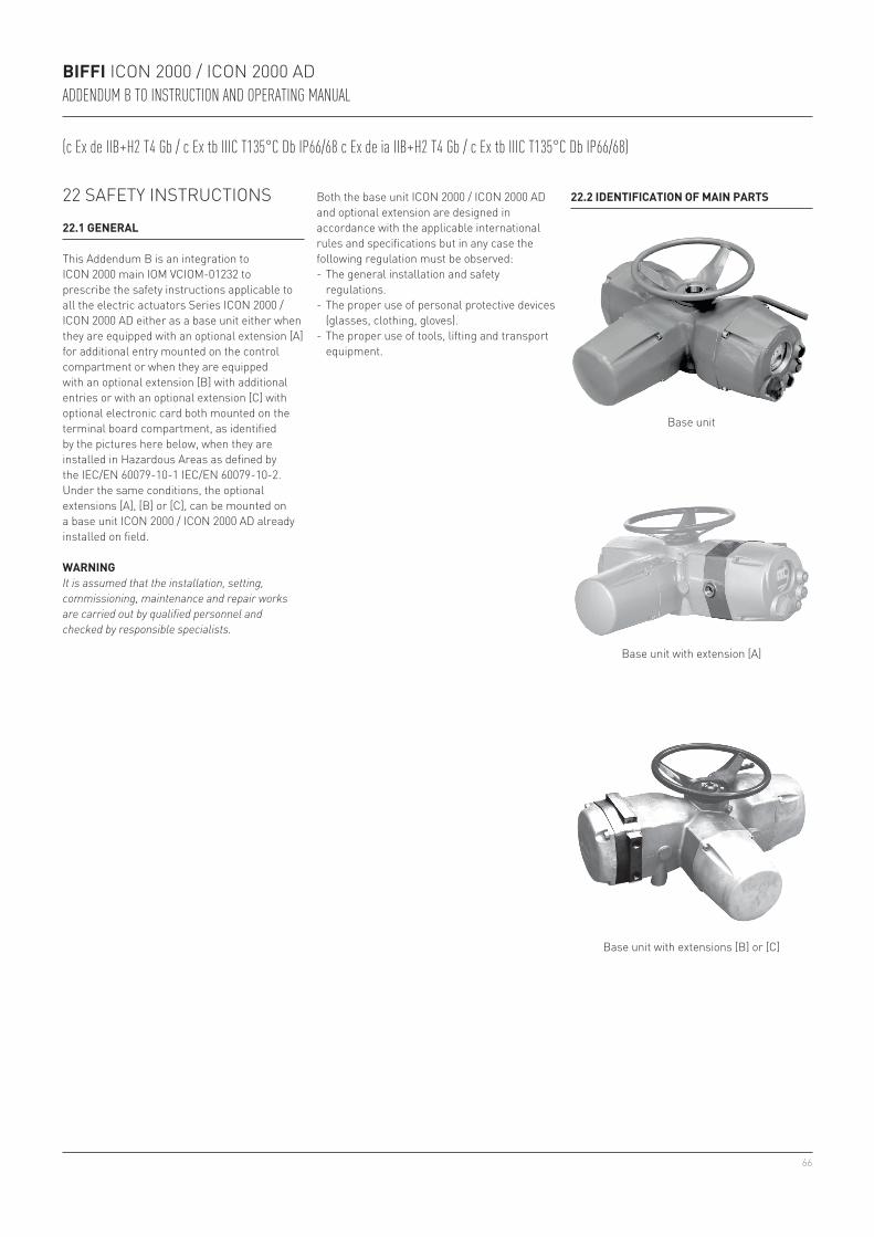
66
BIFFI ICON 2000 / ICON 2000 ADADDENDUM B TO INSTRUCTION AND OPERATING MANUAL
WARNINGIt is assumed that the installation, setting, commissioning, maintenance and repair works are carried out by qualified personnel and checked by responsible specialists.
22 SAFETY INSTRUCTIONS
22.1 GENERAL
This Addendum B is an integration to ICON 2000 main IOM VCIOM-01232 to prescribe the safety instructions applicable to all the electric actuators Series ICON 2000 / ICON 2000 AD either as a base unit either when they are equipped with an optional extension [A] for additional entry mounted on the control compartment or when they are equipped with an optional extension [B] with additional entries or with an optional extension [C] with optional electronic card both mounted on the terminal board compartment, as identified by the pictures here below, when they are installed in Hazardous Areas as defined by the IEC/EN 60079-10-1 IEC/EN 60079-10-2.Under the same conditions, the optional extensions [A], [B] or [C], can be mounted on a base unit ICON 2000 / ICON 2000 AD already installed on field.
Both the base unit ICON 2000 / ICON 2000 AD and optional extension are designed in accordance with the applicable international rules and specifications but in any case the following regulation must be observed:- The general installation and safety
regulations.- The proper use of personal protective devices
(glasses, clothing, gloves).- The proper use of tools, lifting and transport
equipment.
22.2 IDENTIFICATION OF MAIN PARTS
Base unit
Base unit with extension [A]
Base unit with extensions [B] or [C]
(c Ex de IIB+H2 T4 Gb / c Ex tb IIIC T135°C Db IP66/68 c Ex de ia IIB+H2 T4 Gb / c Ex tb IIIC T135°C Db IP66/68)
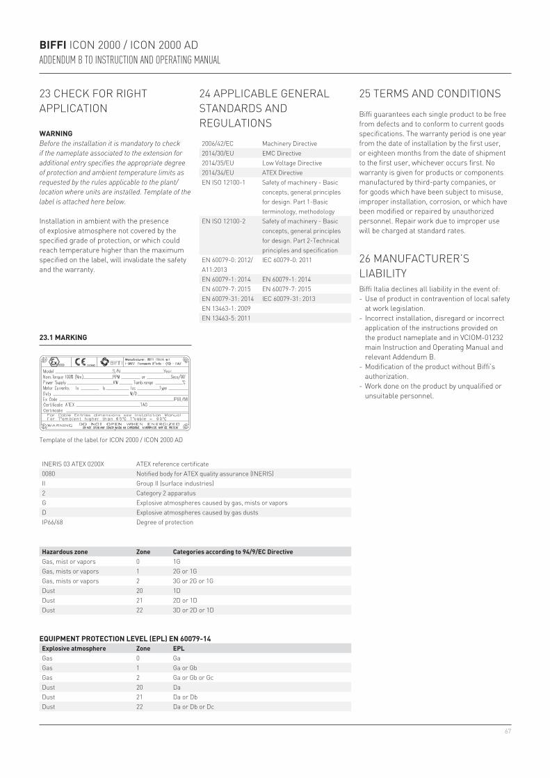
67
BIFFI ICON 2000 / ICON 2000 ADADDENDUM B TO INSTRUCTION AND OPERATING MANUAL
23.1 MARKING
INERIS 03 ATEX 0200X ATEX reference certificate 0080 Notified body for ATEX quality assurance (INERIS) II Group II (surface industries)2 Category 2 apparatus G Explosive atmospheres caused by gas, mists or vaporsD Explosive atmospheres caused by gas dusts IP66/68 Degree of protection
23 CHECK FOR RIGHT APPLICATION
WARNINGBefore the installation it is mandatory to check if the nameplate associated to the extension for additional entry specifies the appropriate degree of protection and ambient temperature limits as requested by the rules applicable to the plant/location where units are installed. Template of the label is attached here below.
Installation in ambient with the presence of explosive atmosphere not covered by the specified grade of protection, or which could reach temperature higher than the maximum specified on the label, will invalidate the safety and the warranty.
Template of the label for ICON 2000 / ICON 2000 AD
Hazardous zone Zone Categories according to 94/9/EC DirectiveGas, mist or vapors 0 1GGas, mists or vapors 1 2G or 1GGas, mists or vapors 2 3G or 2G or 1GDust 20 1DDust 21 2D or 1DDust 22 3D or 2D or 1D
24 APPLICABLE GENERAL STANDARDS AND REGULATIONS
EQUIPMENT PROTECTION LEVEL (EPL) EN 60079-14Explosive atmosphere Zone EPLGas 0 GaGas 1 Ga or GbGas 2 Ga or Gb or GcDust 20 DaDust 21 Da or DbDust 22 Da or Db or Dc
2006/42/EC Machinery Directive2014/30/EU EMC Directive2014/35/EU Low Voltage Directive2014/34/EU ATEX DirectiveEN ISO 12100-1 Safety of machinery - Basic
concepts, general principles for design. Part 1-Basic terminology, methodology
EN ISO 12100-2 Safety of machinery - Basic concepts, general principles for design. Part 2-Technical principles and specification
EN 60079-0: 2012/A11:2013
IEC 60079-0: 2011
EN 60079-1: 2014 EN 60079-1: 2014EN 60079-7: 2015 EN 60079-7: 2015EN 60079-31: 2014 IEC 60079-31: 2013EN 13463-1: 2009EN 13463-5: 2011
25 TERMS AND CONDITIONS
Biffi guarantees each single product to be free from defects and to conform to current goods specifications. The warranty period is one year from the date of installation by the first user, or eighteen months from the date of shipment to the first user, whichever occurs first. No warranty is given for products or components manufactured by third-party companies, or for goods which have been subject to misuse, improper installation, corrosion, or which have been modified or repaired by unauthorized personnel. Repair work due to improper use will be charged at standard rates.
26 MANUFACTURER’S LIABILITYBiffi Italia declines all liability in the event of:- Use of product in contravention of local safety
at work legislation.- Incorrect installation, disregard or incorrect
application of the instructions provided on the product nameplate and in VCIOM-01232 main Instruction and Operating Manual and relevant Addendum B.
- Modification of the product without Biffi’s authorization.
- Work done on the product by unqualified or unsuitable personnel.
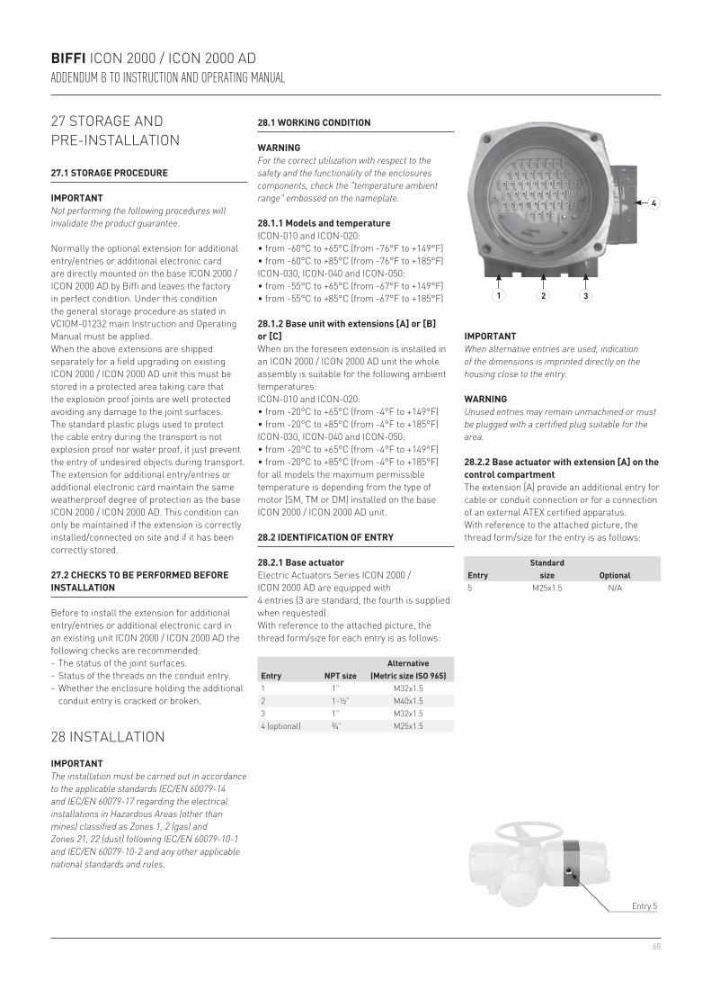
68
4
1 2 3
BIFFI ICON 2000 / ICON 2000 ADADDENDUM B TO INSTRUCTION AND OPERATING MANUAL
27 STORAGE AND PRE-INSTALLATION
27.1 STORAGE PROCEDURE
IMPORTANTNot performing the following procedures will invalidate the product guarantee.
Normally the optional extension for additional entry/entries or additional electronic card are directly mounted on the base ICON 2000 / ICON 2000 AD by Biffi and leaves the factory in perfect condition. Under this condition the general storage procedure as stated in VCIOM-01232 main Instruction and Operating Manual must be applied.When the above extensions are shipped separately for a field upgrading on existing ICON 2000 / ICON 2000 AD unit this must be stored in a protected area taking care that the explosion proof joints are well protected avoiding any damage to the joint surfaces.The standard plastic plugs used to protect the cable entry during the transport is not explosion proof nor water proof, it just prevent the entry of undesired objects during transport.The extension for additional entry/entries or additional electronic card maintain the same weatherproof degree of protection as the base ICON 2000 / ICON 2000 AD. This condition can only be maintained if the extension is correctly installed/connected on site and if it has been correctly stored.
27.2 CHECKS TO BE PERFORMED BEFORE INSTALLATION
Before to install the extension for additional entry/entries or additional electronic card in an existing unit ICON 2000 / ICON 2000 AD the following checks are recommended:- The status of the joint surfaces.- Status of the threads on the conduit entry.- Whether the enclosure holding the additional
conduit entry is cracked or broken.
28 INSTALLATION
IMPORTANTThe installation must be carried out in accordance to the applicable standards IEC/EN 60079-14 and IEC/EN 60079-17 regarding the electrical installations in Hazardous Areas (other than mines) classified as Zones 1, 2 (gas) and Zones 21, 22 (dust) following IEC/EN 60079-10-1 and IEC/EN 60079-10-2 and any other applicable national standards and rules.
IMPORTANTWhen alternative entries are used, indication of the dimensions is imprinted directly on the housing close to the entry.
WARNINGUnused entries may remain unmachined or must be plugged with a certified plug suitable for the area.
Entry NPT sizeAlternative
(Metric size ISO 965)1 1” M32x1.52 1-½” M40x1.53 1” M32x1.54 (optional) ¾” M25x1.5
28.1 WORKING CONDITION
WARNINGFor the correct utilization with respect to the safety and the functionality of the enclosures components, check the "temperature ambient range" embossed on the nameplate.
28.1.1 Models and temperatureICON-010 and ICON-020:• from -60°C to +65°C (from -76°F to +149°F)• from -60°C to +85°C (from -76°F to +185°F)ICON-030, ICON-040 and ICON-050:• from -55°C to +65°C (from -67°F to +149°F)• from -55°C to +85°C (from -67°F to +185°F)
28.1.2 Base unit with extensions [A] or [B] or [C]When on the foreseen extension is installed in an ICON 2000 / ICON 2000 AD unit the whole assembly is suitable for the following ambient temperatures:ICON-010 and ICON-020:• from -20°C to +65°C (from -4°F to +149°F)• from -20°C to +85°C (from -4°F to +185°F)ICON-030, ICON-040 and ICON-050:• from -20°C to +65°C (from -4°F to +149°F)• from -20°C to +85°C (from -4°F to +185°F)for all models the maximum permissible temperature is depending from the type of motor (SM, TM or DM) installed on the base ICON 2000 / ICON 2000 AD unit.
28.2 IDENTIFICATION OF ENTRY
28.2.1 Base actuatorElectric Actuators Series ICON 2000 / ICON 2000 AD are equipped with4 entries (3 are standard, the fourth is supplied when requested).With reference to the attached picture, the thread form/size for each entry is as follows:
Entry 5
EntryStandard
size Optional5 M25x1.5 N/A
28.2.2 Base actuator with extension [A] on the control compartmentThe extension [A] provide an additional entry for cable or conduit connection or for a connection of an external ATEX certified apparatus.With reference to the attached picture, the thread form/size for the entry is as follows:
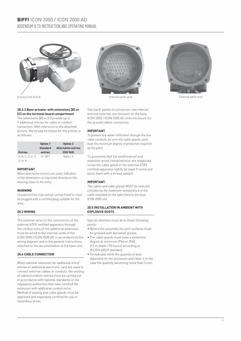
69
BIFFI ICON 2000 / ICON 2000 ADADDENDUM B TO INSTRUCTION AND OPERATING MANUAL
28.2.3 Base actuator with extensions [B] or [C] on the terminal board compartmentThe extensions [B] or [C] provide up to 9 additional entries for cable or conduit connection. With reference to the attached picture, the thread form/size for the entries is as follows:
Entries from A to K
Entries
Option 1 Standard entries
Option 2 Alternative entries
(ISO 965)A, B, C, D, E, F, G, H, K
½” NPT M20x1.5
IMPORTANTWhen alternative entries are used, indication of the dimensions is imprinted directly on the housing close to the entry.
WARNINGUnused entries may remain unmachined or must be plugged with a certified plug suitable for the area.
28.3 WIRING
The external wires or the connections of the external ATEX certified apparatus through the conduit entry of the additional extension, must be wired to the internal cards of the ICON 2000 / ICON 2000 AD in accordance to the wiring diagram and to the general instructions attached to the documentation of the base unit.
28.4 CABLE CONNECTION
When optional extension for additional entry/entries or additional electronic card are used to connect external cables or conduits, the sealing of cables/conduits entries must be carried out in accordance with national standards or the regulatory authorities that have certified the extension with additional conduit entry.Method of sealing and cable glands must be approved and separately certified for use in hazardous areas.
Two earth points of connection, one internal and one external, are foreseen on the base ICON 2000 / ICON 2000 AD units enclosure for the ground cables connection.
Internal earth stud External earth stud
IMPORTANTTo prevent any water infiltration through the line cable conduits, be sure the cable glands used have the minimum degree of protection required by the plant.
To guarantee that the weatherproof and explosion-proof characteristics are respected, screw the cable gland or the external ATEX certified apparatus tightly (at least 5 turns) and block them with a thread sealant.
IMPORTANTThe cables and cable glands MUST be selected considering the maximum temperature of the cable indicated on the label fixed to the base ICON 2000 unit.
28.5 INSTALLATION IN AMBIENT WITH EXPLOSIVE DUSTS
Special attention must do to these following points: • Before the assembly the joint surfaces must
be greased with Aeroshell grease.• The cable glands must have a protection
degree at minimum IP66 or IP68 (15 m depth / 90 hours) according to IEC/EN 60529 standard.
• Periodically verify the quantity of dust deposited on the enclosure and clean it in the case the quantity becoming more than 5 mm.
70
BIFFI ICON 2000 / ICON 2000 ADADDENDUM B TO INSTRUCTION AND OPERATING MANUAL
29.3 REPAIRS
When needed, repair must only be carried out with manufacturer’s original spare parts.
WARNINGThe values of gaps of explosion-proof joints are lower than the maximum specified on tables of IEC/EN 60079-1 Standard and the values of widths of the explosion-proof joints are superior to the values specified on tables of the Standard IEC/EN 60079-1. In case the maintenance should require the replacement of any component which forms part of an explosion-proof joint, only an original spare provided by Biffi MUST be used. Direct repair or reconstruction of the above components are not permitted without the Biffi permission. Not performing this procedure will invalidate the product safety and contractual guarantee.
Original spare parts must be required to the manufacturer: to ensure that right spare is provided, serial number printed on the ICON 2000 unit enclosure label must be specified when spares are ordered.
29.2 DISMANTLING AND REASSEMBLING
WARNINGIn case the screws of the cover must been replaced, a SS AISI 316 Class A4 Grade 70, must be used with minimum yield strength of 450 N/mm2.
In case a dismantling and subsequent reassembling of the explosion-proof enclosure is required, be careful to maintain all parts in their original condition.So the following procedure must be followed:• Do not damage the explosion-proof mating
surfaces on the housing and on the electrical enclosure cover.
29 MAINTENANCE
WARNINGIn case the units equipped with extension for additional entry or additional entries, already installed in HAZARDOUS AREAS, need maintenance and/or any repair work, this must be carried out by personnel specifically qualified and fully trained for works in HAZARDOUS AREAS.
29.1 PERIODIC INSPECTIONS
• Inspect the general conditions of the ICON 2000 / ICON 2000 AD plus the possible optional additional extension at regular intervals: recommended frequency of inspection is one time every two years but this frequency could be changed depending on the installation and working conditions: any crack on the surface, broken window or loose bolts must be reported for repair.
• Keep the external surfaces of the unit clean: if the unit is installed in a dusty environment the specification stated in IEC/EN 60079-14 to be followed ensuring in particular that the dust layer does not exceed 5 mm.
• Check the condition of cable connection and mounting bolts: any loose connection must be amended.
• Reinstall all the screws that go with the dismantled parts and block after spreading them with a film of molybdenum-based grease. This will keep screws from sticking and make maintenance future operations easier.
• In case the screws need to be changed it is mandatory to assure that the new screws are of the same dimension and same material as the original ones as stated in this manual, or of a better quality.
• Replace the weatherproof seals that may have been removed i.e: O-rings for the cover.
• In particular, be sure the joint surfaces of all enclosures are spread with a film of Aeroshell grease.

71
BIFFI ICON 2000 / ICON 2000 ADADDENDUM C TO INSTRUCTION AND OPERATING MANUAL
WARNINGIt is assumed that the installation, setting, commissioning, maintenance and repair works are carried out by qualified personnel and checked by responsible specialists.
30 SAFETY INSTRUCTIONS
30.1 GENERAL
This Addendum C to ICON 2000 main IOM VCIOM-01232 prescribes the safety instructions applicable to all the electric actuators ICON 2000-010 and ICON 2000-020, certified according to the IEC/EN Standards 60079-0, 60079-1, 60079-11, 60079-31 for protection mode Ex db or Ex db ia for gas group IIC and Ex tb IIIC for dust suitable to be installed in an ambient temperature range from -60°C (-76°F) to +85°C (+185°F).
ICON 2000 is designed in accordance with the applicable international rules and specifications but in any case the following regulation must be observed:- The general installation and safety
regulations.- The proper use of personal protective devices
(glasses, clothing, gloves).- The proper use of tools, lifting and transport
equipment.
31 INSTRUCTIONS FOR RIGHT INSTALLATION
WARNINGBefore the installation it is mandatory to check if the nameplate specifies the appropriate degree of protection and ambient temperature limits as requested by the rules applicable to the plant/location where ICON 2000 are installed.Installation in ambient with the presence of explosive atmosphere not covered by the specified grade of protection, or which could reach temperature higher than the maximum specified on the label, will invalidate the safety and the warranty.
IMPORTANTCheck if the label, as the following example, is fixed on the unit and completed with all the appropriate information.
31.1 MARKING
Template of the label for ICON 2000 / ICON 2000 AD
(c Ex de IIB+H2 T4 Gb / c Ex tb IIIC T135°C Db IP66/68 c Ex de ia IIB+H2 T4 Gb / c Ex tb IIIC T135°C Db IP66/68)

72
BIFFI ICON 2000 / ICON 2000 ADADDENDUM C TO INSTRUCTION AND OPERATING MANUAL
INERIS 03 ATEX 0200X ATEX reference certificate 0080 Notified body for ATEX quality assurance (INERIS) II Group II (surface industries)2 Category 2 apparatus G Explosive atmospheres caused by gas, mists or vaporsD Explosive atmospheres caused by gas dusts IP66/68 Degree of protection
Hazardous zone Zone Categories according to 94/9/EC DirectiveGas, mist or vapors 0 1GGas, mists or vapors 1 2G or 1GGas, mists or vapors 2 3G or 2G or 1GDust 20 1DDust 21 2D or 1DDust 22 3D or 2D or 1D
32 APPLICABLE DIRECTIVES, GENERAL STANDARDS AND NORMS
EQUIPMENT PROTECTION LEVEL (EPL) EN 60079-14Explosive atmosphere Zone EPLGas 0 GaGas 1 Ga or GbGas 2 Ga or Gb or GcDust 20 DaDust 21 Da or DbDust 22 Da or Db or Dc
2006/42/EC Machinery Directive2014/30/EU EMC Directive2014/35/EU Low Voltage Directive2014/34/EU ATEX DirectiveEN ISO 12100-1 Safety of machinery - Basic
concepts, general principles for design. Part 1-Basic terminology, methodology
EN ISO 12100-2 Safety of machinery - Basic concepts, general principles for design. Part 2-Technical principles and specification
EN 60079-0: 2012/A11:2013
IEC 60079-0: 2011
EN 60079-1: 2014 EN 60079-1: 2014EN 60079-11: 2012 IEC 60079-11: 2011EN 60079-31: 2014 IEC 60079-31: 2013EN 13463-1: 2009EN 13463-5: 2011
33 TERMS AND CONDITIONS
Biffi Italia guarantees each single product to be free from defects and to conform to current goods specifications. Except when differently specified, the warranty period in one year from the date of installation by the first user, or eighteen months from the date of shipment to the first user, whichever occurs first.No warranty is given for products which have been subject to improper storage, improper installation, misuse, or which have been modified or repaired by unauthorized personnel.Repair works due to improper use will be charged at standard rates.
34 MANUFACTURER’S LIABILITYBiffi Italia declines all liability in the event of:- Use of product in contravention of local safety
at work legislation.- Incorrect installation, disregard or incorrect
application of the instructions provided on the product nameplate and in VCIOM-01232 main Instruction and Operating Manual and relevant Addendum C.
- Modification of the product without Biffi’s authorisation.
- Work done on the product by unqualified or unsuitable personnel.
35 STORAGE AND PRE-INSTALLATION
35.1 STORAGE PROCEDURE
IMPORTANTNot performing the following procedures will invalidate the product guarantee.
Normally the optional extension for additional entry/entries or additional electronic card are directly mounted on the base ICON 2000 / ICON 2000 AD by Biffi and leaves the factory in perfect condition. Under this condition the general storage procedure as stated in the main IOM must be applied.When the above extensions are shipped separately for a field upgrading on existing ICON 2000 / ICON 2000 AD unit this must be stored in a protected area taking care that the explosion proof joints are well protected avoiding any damage to the joint surfaces.The standard plastic plugs used to protect the cable entry during the transport is not explosion proof nor water proof, it just prevent the entry of undesired objects during transport.The extension for additional entry/entries or additional electronic card maintain the same weatherproof degree of protection as the base ICON 2000 / ICON 2000 AD. This condition can only be maintained if the extension is correctly installed/connected on site and if it has been correctly stored.
35.2 CHECKS TO BE PERFORMED BEFORE INSTALLATION
Before to install the extension for additional entry/entries or additional electronic card in an existing unit ICON 2000 / ICON 2000 AD the following checks are recommended:- The status of the joint surfaces.- Status of the threads on the conduit entry.- Whether the enclosure holding the additional
conduit entry is cracked or broken.
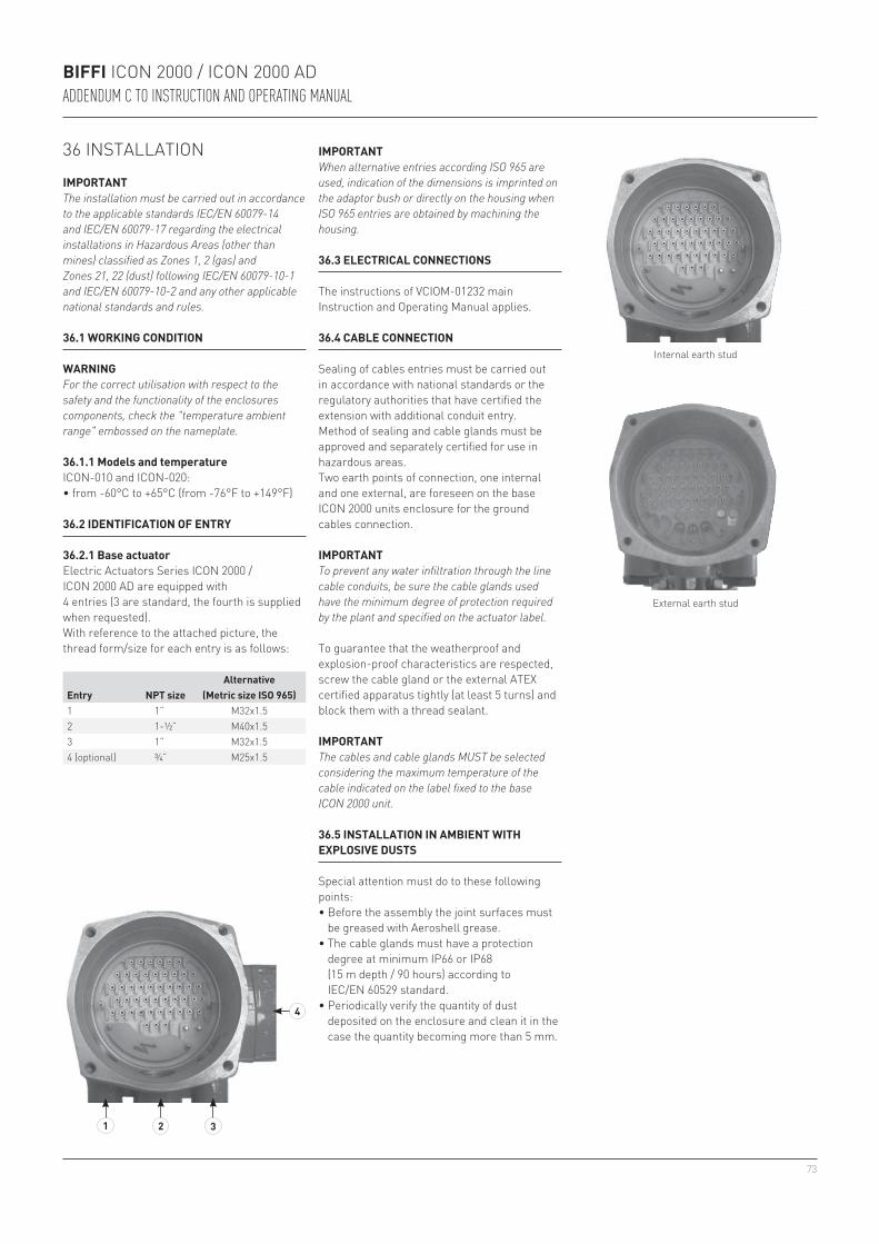
73
4
1 2 3
BIFFI ICON 2000 / ICON 2000 ADADDENDUM C TO INSTRUCTION AND OPERATING MANUAL
36 INSTALLATION
IMPORTANTThe installation must be carried out in accordance to the applicable standards IEC/EN 60079-14 and IEC/EN 60079-17 regarding the electrical installations in Hazardous Areas (other than mines) classified as Zones 1, 2 (gas) and Zones 21, 22 (dust) following IEC/EN 60079-10-1 and IEC/EN 60079-10-2 and any other applicable national standards and rules.
36.1 WORKING CONDITION
WARNINGFor the correct utilisation with respect to the safety and the functionality of the enclosures components, check the "temperature ambient range" embossed on the nameplate.
36.1.1 Models and temperatureICON-010 and ICON-020:• from -60°C to +65°C (from -76°F to +149°F)
IMPORTANTWhen alternative entries according ISO 965 are used, indication of the dimensions is imprinted on the adaptor bush or directly on the housing when ISO 965 entries are obtained by machining the housing.
Entry NPT sizeAlternative
(Metric size ISO 965)1 1” M32x1.52 1-½” M40x1.53 1” M32x1.54 (optional) ¾” M25x1.5
36.2 IDENTIFICATION OF ENTRY
36.2.1 Base actuatorElectric Actuators Series ICON 2000 / ICON 2000 AD are equipped with4 entries (3 are standard, the fourth is supplied when requested).With reference to the attached picture, the thread form/size for each entry is as follows:
36.3 ELECTRICAL CONNECTIONS
The instructions of VCIOM-01232 main Instruction and Operating Manual applies.
36.4 CABLE CONNECTION
Sealing of cables entries must be carried out in accordance with national standards or the regulatory authorities that have certified the extension with additional conduit entry.Method of sealing and cable glands must be approved and separately certified for use in hazardous areas.Two earth points of connection, one internal and one external, are foreseen on the base ICON 2000 units enclosure for the ground cables connection.
IMPORTANTTo prevent any water infiltration through the line cable conduits, be sure the cable glands used have the minimum degree of protection required by the plant and specified on the actuator label.
To guarantee that the weatherproof and explosion-proof characteristics are respected, screw the cable gland or the external ATEX certified apparatus tightly (at least 5 turns) and block them with a thread sealant.
IMPORTANTThe cables and cable glands MUST be selected considering the maximum temperature of the cable indicated on the label fixed to the base ICON 2000 unit.
36.5 INSTALLATION IN AMBIENT WITH EXPLOSIVE DUSTS
Special attention must do to these following points: • Before the assembly the joint surfaces must
be greased with Aeroshell grease.• The cable glands must have a protection
degree at minimum IP66 or IP68 (15 m depth / 90 hours) according to IEC/EN 60529 standard.
• Periodically verify the quantity of dust deposited on the enclosure and clean it in the case the quantity becoming more than 5 mm.
Internal earth stud
External earth stud
74
BIFFI ICON 2000 / ICON 2000 ADADDENDUM C TO INSTRUCTION AND OPERATING MANUAL
37.3 REPAIRS
When needed, repair must only be carried out with manufacturer’s original spare parts.
WARNINGThe values of gaps of explosion-proof joints are lower than the maximum specified on tables of IEC/EN 60079-1 Standard. In case the maintenance should require the replacement of any component which forms part of an explosion-proof joint, only an original spare provided by Biffi MUST be used. Direct repair or reconstruction of the above components are not permitted without the Biffi permission. Not performing this procedure will invalidate the product safety and contractual guarantee.
Original spare parts must be required to the manufacturer: to ensure that right spare is provided, serial number printed on the ICON 2000 unit enclosure label must be specified when spares are ordered.
37.2 DISMANTLING AND REASSEMBLING
WARNINGIn case the screws of the Ex-d covers must been replaced, a SS AISI 316 Class A4 Grade 70, must be used with minimum yield strength of 450 N/mm2.
In case a dismantling and subsequent reassembling of the explosion-proof enclosure is required, be careful to maintain all parts in their original condition.So the following procedure must be followed:• Do not damage the explosion-proof mating
surfaces on the housing and on the electrical enclosure cover.
37 MAINTENANCE
WARNINGIn case the unit already installed in HAZARDOUS AREAS, need maintenance and/or any repair work, this must be carried out by personnel specifically qualified and fully trained for works in HAZARDOUS AREAS.
37.1 PERIODIC INSPECTIONS
• Inspect the general conditions of the ICON 2000 at regular intervals: recommended frequency of inspection is one time every two years but this frequency could be changed depending on the installation and working conditions: any crack on the surface, broken window or loose bolts must be reported for repair.
• Keep the external surfaces of the unit clean: if the unit is installed in a dusty environment the specification stated in IEC/EN 60079-14 to be followed ensuring in particular that the dust layer does not exceed 5 mm.
• Check the condition of cable connection and mounting bolts: any loose connection must be amended.
• Reinstall all the screws that go with the dismantled parts and block after spreading them with a film of molybdenum-based grease. This will keep screws from sticking and make maintenance future operations easier.
• In case the screws need to be changed it is mandatory to assure that the new screws are of the same dimension and same material as the original ones as stated in this manual, or of a better quality.
• Replace the weatherproof seals that may have been removed i.e: O-rings for the cover.
• In particular, be sure the joint surfaces of all enclosures are spread with a film of Aeroshell grease.

75
BIFFI ICON 2000 / ICON 2000 ADADDENDUM D TO INSTRUCTION AND OPERATING MANUAL
WARNINGIt is assumed that the installation, setting, commissioning, maintenance and repair works are carried out by qualified personnel and checked by responsible specialists.
38 SAFETY INSTRUCTIONS
38.1 GENERAL
This Addendum D to ICON 2000 main IOM VCIOM-01232 prescribes the safety instructions applicable to all the electric actuators ICON 2000-010, ICON-020, ICON-030, certified according to the IEC/EN 60079-0, 60079-1, 60079-7, 60079-11 and 60079-31 standards, for protection mode Ex d e and gas group IIC suitable to be installed in an ambient temperature range from -25°C (-13°F) to +60°C (+140°F).
ICON 2000 is designed in accordance with the applicable international rules and specifications but in any case the following regulation must be observed:- The general installation and safety
regulations.- The proper use of personal protective devices
(glasses, clothing, gloves).- The proper use of tools, lifting and transport
equipment.
39 INSTRUCTIONS FOR RIGHT INSTALLATION
WARNINGBefore the installation it is mandatory to check if the nameplate specifies the appropriate degree of protection and ambient temperature limits as requested by the rules applicable to the plant/location where ICON 2000 are installed.Installation in ambient with the presence of explosive atmosphere not covered by the specified grade of protection, or which could reach temperature higher than the maximum specified on the label, will invalidate the safety and the warranty.
IMPORTANTCheck if the label, as the following example, is fixed on the unit and completed with all the appropriate information.
39.1 MARKING
Template of the label for ICON 2000 / ICON 2000 AD
(c Ex de IIB+H2 T4 Gb / c Ex tb IIIC T135°C Db IP66/68 c Ex de ia IIB+H2 T4 Gb / c Ex tb IIIC T135°C Db IP66/68)

76
BIFFI ICON 2000 / ICON 2000 ADADDENDUM D TO INSTRUCTION AND OPERATING MANUAL
INERIS 03 ATEX 0200X ATEX reference certificate 0080 Notified body for ATEX quality assurance (INERIS) II Group II (surface industries)2 Category 2 apparatus G Explosive atmospheres caused by gas, mists or vaporsD Explosive atmospheres caused by gas dusts IP66/68 Degree of protection
Hazardous zone Zone Categories according to 94/9/EC DirectiveGas, mist or vapors 0 1GGas, mists or vapors 1 2G or 1GGas, mists or vapors 2 3G or 2G or 1GDust 20 1DDust 21 2D or 1DDust 22 3D or 2D or 1D
40 APPLICABLE DIRECTIVES, GENERAL STANDARDS AND NORMS
EQUIPMENT PROTECTION LEVEL (EPL) EN 60079-14Explosive atmosphere Zone EPLGas 0 GaGas 1 Ga or GbGas 2 Ga or Gb or GcDust 20 DaDust 21 Da or DbDust 22 Da or Db or Dc
2006/42/EC Machinery Directive2014/30/EU EMC Directive2014/35/EU Low Voltage Directive2014/34/EU ATEX DirectiveEN ISO 12100-1 Safety of machinery -
Basic concepts, general principles for design. Part 1-Basic terminology, methodology
EN ISO 12100-2 Safety of machinery - Basic concepts, general principles for design. Part 2-Technical principles and specification
EN 60079-0: 2012/A11:2013
IEC 60079-0: 2011
EN 60079-1: 2014 EN 60079-1: 2014EN 60079-7: 2015 EN 60079-7: 2015EN 60079-11: 2012 IEC 60079-11: 2011EN 60079-31: 2014 IEC 60079-31: 2013EN 13463-1: 2009EN 13463-5: 2011
41 TERMS AND CONDITIONS
Biffi Italia guarantees each single product to be free from defects and to conform to current goods specifications. Except when differently specified, the warranty period in one year from the date of installation by the first user, or eighteen months from the date of shipment to the first user, whichever occurs first.No warranty is given for products which have been subject to improper storage, improper installation, misuse, or which have been modified or repaired by unauthorized personnel.Repair works due to improper use will be charged at standard rates.
42 MANUFACTURER’S LIABILITYBiffi Italia declines all liability in the event of:- Use of product in contravention of local safety
at work legislation.- Incorrect installation, disregard or incorrect
application of the instructions provided on the product nameplate and in VCIOM-01232 main Instruction and Operating Manual and relevant Addendum D.
- Modification of the product without Biffi’s authorisation.
- Work done on the product by unqualified or unsuitable personnel.
43 STORAGE AND PRE-INSTALLATION
43.1 STORAGE PROCEDURE
IMPORTANTNot performing the following procedures will invalidate the product guarantee.
Normally the optional extension for additional entry/entries or additional electronic card are directly mounted on the base ICON 2000 / ICON 2000 AD by Biffi and leaves the factory in perfect condition. Under this condition the general storage procedure as stated in the main IOM must be applied.When the above extensions are shipped separately for a field upgrading on existing ICON 2000 / ICON 2000 AD unit this must be stored in a protected area taking care that the explosion proof joints are well protected avoiding any damage to the joint surfaces.The standard plastic plugs used to protect the cable entry during the transport is not explosion proof nor water proof, it just prevent the entry of undesired objects during transport.The extension for additional entry/entries or additional electronic card maintain the same weatherproof degree of protection as the base ICON 2000 / ICON 2000 AD. This condition can only be maintained if the extension is correctly installed/connected on site and if it has been correctly stored.
43.2 CHECKS TO BE PERFORMED BEFORE INSTALLATION
Before to install the extension for additional entry/entries or additional electronic card in an existing unit ICON 2000 / ICON 2000 AD the following checks are recommended:- The status of the joint surfaces.- Status of the threads on the conduit entry.- Whether the enclosure holding the additional
conduit entry is cracked or broken.

77
4
1 2 3
BIFFI ICON 2000 / ICON 2000 ADADDENDUM D TO INSTRUCTION AND OPERATING MANUAL
44 INSTALLATION
IMPORTANTThe installation must be carried out in accordance to the applicable standards IEC/EN 60079-14 and IEC/EN 60079-17 regarding the electrical installations in Hazardous Areas (other than mines) classified as Zones 1, 2 (gas) and Zones 21, 22 (dust) following IEC/EN 60079-10-1 and IEC/EN 60079-10-2 and any other applicable national standards and rules.
44.1 WORKING CONDITION
WARNINGFor the correct utilisation with respect to the safety and the functionality of the enclosures components, check the "temperature ambient range" embossed on the nameplate.
44.1.1 Models and temperatureICON-010, ICON-020 and ICON-030:• from -25°C to +60°C (from -13°F to +140°F)
IMPORTANTWhen alternative entries according ISO 965 are used, indication of the dimensions is imprinted on the adaptor bush or directly on the housing when ISO 965 entries are obtained by machining the housing.
Entry NPT sizeAlternative
(Metric size ISO 965)1 1” M32x1.52 1-½” M40x1.53 1” M32x1.54 (optional) ¾” M25x1.5
44.2 IDENTIFICATION OF ENTRIES
44.2.1 Base actuatorElectric actuators Series ICON 2000 / ICON 2000 AD are equipped with 4 entries (3 are standard, the fourth is supplied when requested).With reference to the attached picture, the thread form/size for each entry is as follows:
44.3 ELECTRICAL CONNECTIONS
The instructions of VCIOM-01232 main Instruction and Operating Manual applies.
44.4 CABLE CONNECTION
Sealing of cables entries must be carried out in accordance with national standards or the regulatory authorities that have certified the extension with additional conduit entry.Method of sealing and cable glands must be approved and separately certified for use in hazardous areas.Two earth points of connection, one internal and one external, are foreseen on the base ICON 2000 units enclosure for the ground cables connection.
IMPORTANTTo prevent any water infiltration through the line cable conduits, be sure the cable glands used have the minimum degree of protection required by the plant and specified on the actuator label.
To guarantee that the weatherproof and explosion-proof characteristics are respected, screw the cable gland or the external ATEX certified apparatus tightly (at least 5 turns) and block them with a thread sealant.
IMPORTANTThe cables and cable glands MUST be selected considering the maximum temperature of the cable indicated on the label fixed to the base ICON 2000 unit.
44.5 INSTALLATION IN AMBIENT WITH EXPLOSIVE DUSTS
Special attention must do to these following points: • Before the assembly the joint surfaces must
be greased with Aeroshell grease.• The cable glands must have a protection
degree at minimum IP66 or IP68 (15 m depth / 90 hours) according to IEC/EN 60529 standard.
• Periodically verify the quantity of dust deposited on the enclosure and clean it in the case the quantity becoming more than 5 mm.
Internal earth stud
External earth stud
78
BIFFI ICON 2000 / ICON 2000 ADADDENDUM D TO INSTRUCTION AND OPERATING MANUAL
45.3 REPAIRS
When needed, repair must only be carried out with manufacturer’s original spare parts.
WARNINGThe values of gaps of explosion-proof joints are lower than the maximum specified on tables of IEC/EN 60079-1 Standard. In case the maintenance should require the replacement of any component which forms part of an explosion-proof joint, only an original spare provided by Biffi MUST be used. Direct repair or reconstruction of the above components are not permitted without the Biffi permission. Not performing this procedure will invalidate the product safety and contractual guarantee.
Original spare parts must be required to the manufacturer: to ensure that right spare is provided, serial number printed on the ICON 2000 unit enclosure label must be specified when spares are ordered.
45.2 DISMANTLING AND REASSEMBLING
WARNINGIn case the screws of the Ex-d covers must been replaced, a SS AISI 316 Class A4 Grade 70, must be used with minimum yield strength of 450 N/mm2.
In case a dismantling and subsequent reassembling of the explosion-proof enclosure is required, be careful to maintain all parts in their original condition.So the following procedure must be followed:• Do not damage the explosion-proof mating
surfaces on the housing and on the electrical enclosure cover.
45 MAINTENANCE
WARNINGIn case the unit already installed in HAZARDOUS AREAS, need maintenance and/or any repair work, this must be carried out by personnel specifically qualified and fully trained for works in HAZARDOUS AREAS.
45.1 PERIODIC INSPECTIONS
• Inspect the general conditions of the ICON 2000 at regular intervals: recommended frequency of inspection is one time every two years but this frequency could be changed depending on the installation and working conditions: any crack on the surface, broken window or loose bolts must be reported for repair.
• Keep the external surfaces of the unit clean: if the unit is installed in a dusty environment the specification stated in IEC/EN 60079-14 to be followed ensuring in particular that the dust layer does not exceed 5 mm.
• Check the condition of cable connection and mounting bolts: any loose connection must be amended.
• Reinstall all the screws that go with the dismantled parts and block after spreading them with a film of molybdenum-based grease. This will keep screws from sticking and make maintenance future operations easier.
• In case the screws need to be changed it is mandatory to assure that the new screws are of the same dimension and same material as the original ones as stated in this manual, or of a better quality.
• Replace the weatherproof seals that may have been removed i.e: O-rings for the cover.
• In particular, be sure the joint surfaces of all enclosures are spread with a film of Aeroshell grease.

79
BIFFI ICON 2000 / ICON 2000 ADADDENDUM E TO INSTRUCTION AND OPERATING MANUAL
WARNINGIt is assumed that the installation, setting, commissioning, maintenance and repair works are carried out by qualified personnel and checked by responsible specialists.
46 SAFETY INSTRUCTIONS
46.1 GENERAL
This Addendum E to ICON 2000 main IOM VCIOM-01232 prescribes the safety instructions applicable to all the electric actuators ICON 2000-010, ICON-020, ICON-030, certified according to the IEC/EN 60079-0, 60079-1, 60079-7, 60079-11 and 60079-31 standards, for protection mode Ex d e and gas group IIC suitable to be installed in an ambient temperature range from -25°C (-13°F) to +60°C (+140°F).
ICON 2000 is designed in accordance with the applicable international rules and specifications but in any case the following regulation must be observed:- The general installation and safety
regulations.- The proper use of personal protective devices
(glasses, clothing, gloves).- The proper use of tools, lifting and transport
equipment.
47 INSTRUCTIONS FOR RIGHT INSTALLATION
WARNINGBefore the installation it is mandatory to check if the nameplate specifies the appropriate degree of protection and ambient temperature limits as requested by the rules applicable to the plant/location where ICON 2000 are installed.Installation in ambient with the presence of explosive atmosphere not covered by the specified grade of protection, or which could reach temperature higher than the maximum specified on the label, will invalidate the safety and the warranty.
IMPORTANTCheck if the label, as the following example, is fixed on the unit and completed with all the appropriate information.
47.1 MARKING
Template of the label for ICON 2000 / ICON 2000 AD
(c Ex de IIB+H2 T4 Gb / c Ex tb IIIC T135°C Db IP66/68 c Ex de ia IIB+H2 T4 Gb / c Ex tb IIIC T135°C Db IP66/68)

80
BIFFI ICON 2000 / ICON 2000 ADADDENDUM E TO INSTRUCTION AND OPERATING MANUAL
INERIS 03 ATEX 0200X ATEX reference certificate 0080 Notified body for ATEX quality assurance (INERIS) II Group II (surface industries)2 Category 2 apparatus G Explosive atmospheres caused by gas, mists or vaporsD Explosive atmospheres caused by gas dusts IP66/68 Degree of protection
Hazardous zone Zone Categories according to 94/9/EC DirectiveGas, mist or vapors 0 1GGas, mists or vapors 1 2G or 1GGas, mists or vapors 2 3G or 2G or 1GDust 20 1DDust 21 2D or 1DDust 22 3D or 2D or 1D
48 APPLICABLE DIRECTIVES, GENERAL STANDARDS AND NORMS
EQUIPMENT PROTECTION LEVEL (EPL) EN 60079-14Explosive atmosphere Zone EPLGas 0 GaGas 1 Ga or GbGas 2 Ga or Gb or GcDust 20 DaDust 21 Da or DbDust 22 Da or Db or Dc
2006/42/EC Machinery Directive2014/30/EU EMC Directive2014/35/EU Low Voltage Directive2014/34/EU ATEX DirectiveEN ISO 12100-1 Safety of machinery -
Basic concepts, general principles for design. Part 1-Basic terminology, methodology
EN ISO 12100-2 Safety of machinery - Basic concepts, general principles for design. Part 2-Technical principles and specification
EN 60079-0: 2012/A11:2013
IEC 60079-0: 2011
EN 60079-1: 2014 EN 60079-1: 2014EN 60079-7: 2015 EN 60079-7: 2015EN 60079-11: 2012 IEC 60079-11: 2011EN 60079-31: 2014 IEC 60079-31: 2013EN 13463-1: 2009EN 13463-5: 2011
49 TERMS AND CONDITIONS
Biffi Italia guarantees each single product to be free from defects and to conform to current goods specifications. Except when differently specified, the warranty period in one year from the date of installation by the first user, or eighteen months from the date of shipment to the first user, whichever occurs first.No warranty is given for products which have been subject to improper storage, improper installation, misuse, or which have been modified or repaired by unauthorized personnel.Repair works due to improper use will be charged at standard rates.
50 MANUFACTURER’S LIABILITYBiffi Italia declines all liability in the event of:- Use of product in contravention of local safety
at work legislation.- Incorrect installation, disregard or incorrect
application of the instructions provided on the product nameplate and in VCIOM-01232 main Instruction and Operating Manual and relevant Addendum E.
- Modification of the product without Biffi’s authorisation.
- Work done on the product by unqualified or unsuitable personnel.
51 STORAGE AND PRE-INSTALLATION
51.1 STORAGE PROCEDURE
IMPORTANTNot performing the following procedures will invalidate the product guarantee.
Normally the optional extension for additional entry/entries or additional electronic card are directly mounted on the base ICON 2000 / ICON 2000 AD by Biffi and leaves the factory in perfect condition. Under this condition the general storage procedure as stated in the main IOM must be applied.When the above extensions are shipped separately for a field upgrading on existing ICON 2000 / ICON 2000 AD unit this must be stored in a protected area taking care that the explosion proof joints are well protected avoiding any damage to the joint surfaces.The standard plastic plugs used to protect the cable entry during the transport is not explosion proof nor water proof, it just prevent the entry of undesired objects during transport.The extension for additional entry/entries or additional electronic card maintain the same weatherproof degree of protection as the base ICON 2000 / ICON 2000 AD. This condition can only be maintained if the extension is correctly installed/connected on site and if it has been correctly stored.
51.2 CHECKS TO BE PERFORMED BEFORE INSTALLATION
Before to install the extension for additional entry/entries or additional electronic card in an existing unit ICON 2000 / ICON 2000 AD the following checks are recommended:- The status of the joint surfaces.- Status of the threads on the conduit entry.- Whether the enclosure holding the additional
conduit entry is cracked or broken.
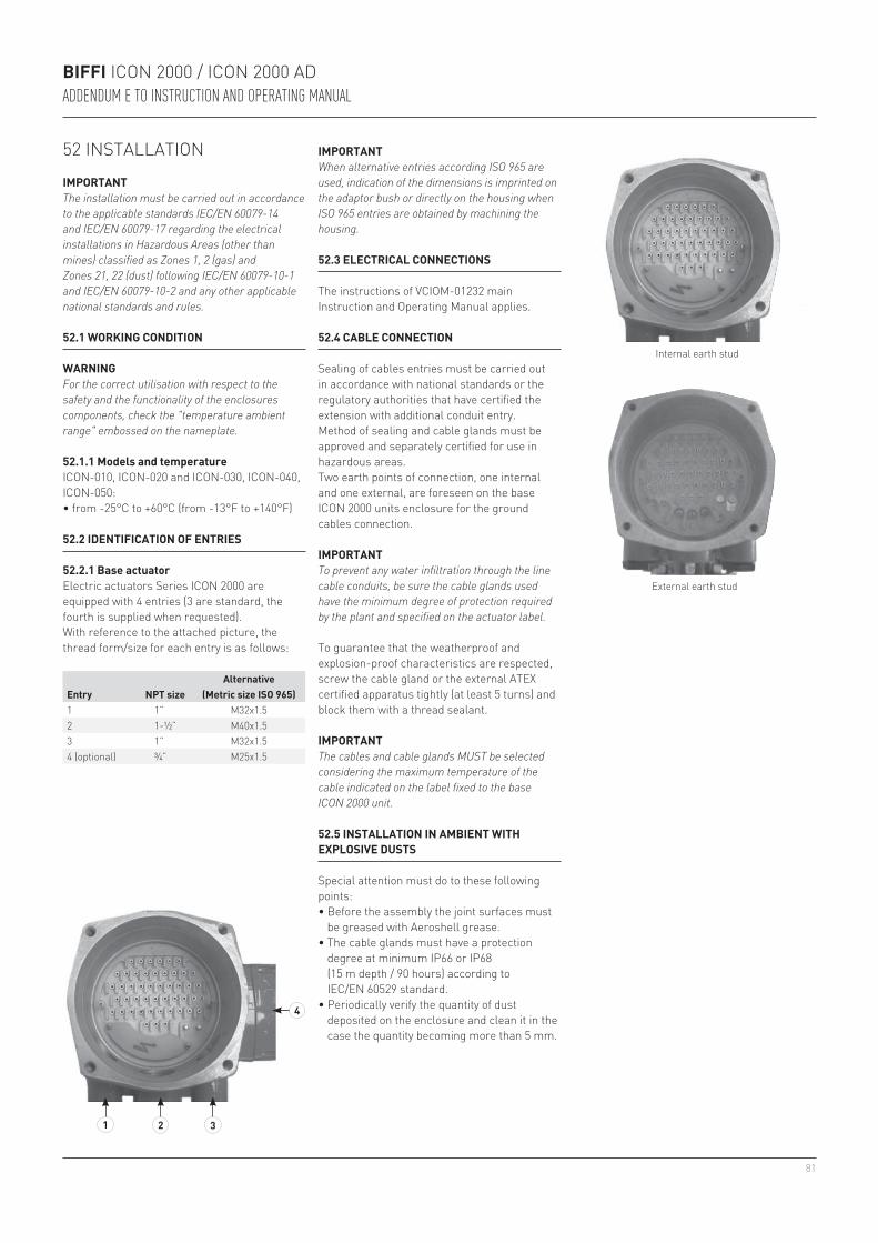
81
4
1 2 3
BIFFI ICON 2000 / ICON 2000 ADADDENDUM E TO INSTRUCTION AND OPERATING MANUAL
52 INSTALLATION
IMPORTANTThe installation must be carried out in accordance to the applicable standards IEC/EN 60079-14 and IEC/EN 60079-17 regarding the electrical installations in Hazardous Areas (other than mines) classified as Zones 1, 2 (gas) and Zones 21, 22 (dust) following IEC/EN 60079-10-1 and IEC/EN 60079-10-2 and any other applicable national standards and rules.
52.1 WORKING CONDITION
WARNINGFor the correct utilisation with respect to the safety and the functionality of the enclosures components, check the "temperature ambient range" embossed on the nameplate.
52.1.1 Models and temperatureICON-010, ICON-020 and ICON-030, ICON-040, ICON-050:• from -25°C to +60°C (from -13°F to +140°F)
IMPORTANTWhen alternative entries according ISO 965 are used, indication of the dimensions is imprinted on the adaptor bush or directly on the housing when ISO 965 entries are obtained by machining the housing.
Entry NPT sizeAlternative
(Metric size ISO 965)1 1” M32x1.52 1-½” M40x1.53 1” M32x1.54 (optional) ¾” M25x1.5
52.2 IDENTIFICATION OF ENTRIES
52.2.1 Base actuatorElectric actuators Series ICON 2000 are equipped with 4 entries (3 are standard, the fourth is supplied when requested).With reference to the attached picture, the thread form/size for each entry is as follows:
52.3 ELECTRICAL CONNECTIONS
The instructions of VCIOM-01232 main Instruction and Operating Manual applies.
52.4 CABLE CONNECTION
Sealing of cables entries must be carried out in accordance with national standards or the regulatory authorities that have certified the extension with additional conduit entry.Method of sealing and cable glands must be approved and separately certified for use in hazardous areas.Two earth points of connection, one internal and one external, are foreseen on the base ICON 2000 units enclosure for the ground cables connection.
IMPORTANTTo prevent any water infiltration through the line cable conduits, be sure the cable glands used have the minimum degree of protection required by the plant and specified on the actuator label.
To guarantee that the weatherproof and explosion-proof characteristics are respected, screw the cable gland or the external ATEX certified apparatus tightly (at least 5 turns) and block them with a thread sealant.
IMPORTANTThe cables and cable glands MUST be selected considering the maximum temperature of the cable indicated on the label fixed to the base ICON 2000 unit.
52.5 INSTALLATION IN AMBIENT WITH EXPLOSIVE DUSTS
Special attention must do to these following points: • Before the assembly the joint surfaces must
be greased with Aeroshell grease.• The cable glands must have a protection
degree at minimum IP66 or IP68 (15 m depth / 90 hours) according to IEC/EN 60529 standard.
• Periodically verify the quantity of dust deposited on the enclosure and clean it in the case the quantity becoming more than 5 mm.
Internal earth stud
External earth stud
82
vn.linkedin.com/company/biffi-italia-srl
www.youtube.com/user/BiffiItaliaSrl
www.biffi.it
BIFFI ICON 2000 / ICON 2000 ADADDENDUM E TO INSTRUCTION AND OPERATING MANUAL
53.3 REPAIRS
When needed, repair must only be carried out with manufacturer’s original spare parts.
WARNINGThe values of gaps of explosion-proof joints are lower than the maximum specified on tables of IEC/EN 60079-1 Standard. In case the maintenance should require the replacement of any component which forms part of an explosion-proof joint, only an original spare provided by Biffi MUST be used. Direct repair or reconstruction of the above components are not permitted without the Biffi permission. Not performing this procedure will invalidate the product safety and contractual guarantee.
Original spare parts must be required to the manufacturer: to ensure that right spare is provided, serial number printed on the ICON 2000 unit enclosure label must be specified when spares are ordered.
53.2 DISMANTLING AND REASSEMBLING
WARNINGIn case the screws of the Ex-d covers must been replaced, a SS AISI 316 Class A4 Grade 70, must be used with minimum yield strength of 450 N/mm2.
In case a dismantling and subsequent reassembling of the explosion-proof enclosure is required, be careful to maintain all parts in their original condition.So the following procedure must be followed:• Do not damage the explosion-proof mating
surfaces on the housing and on the electrical enclosure cover.
53 MAINTENANCE
WARNINGIn case the unit already installed in HAZARDOUS AREAS, need maintenance and/or any repair work, this must be carried out by personnel specifically qualified and fully trained for works in HAZARDOUS AREAS.
53.1 PERIODIC INSPECTIONS
• Inspect the general conditions of the ICON 2000 at regular intervals: recommended frequency of inspection is one time every two years but this frequency could be changed depending on the installation and working conditions: any crack on the surface, broken window or loose bolts must be reported for repair.
• Keep the external surfaces of the unit clean: if the unit is installed in a dusty environment the specification stated in IEC/EN 60079-14 to be followed ensuring in particular that the dust layer does not exceed 5 mm.
• Check the condition of cable connection and mounting bolts: any loose connection must be amended.
• Reinstall all the screws that go with the dismantled parts and block after spreading them with a film of molybdenum-based grease. This will keep screws from sticking and make maintenance future operations easier.
• In case the screws need to be changed it is mandatory to assure that the new screws are of the same dimension and same material as the original ones as stated in this manual, or of a better quality.
• Replace the weatherproof seals that may have been removed i.e: O-rings for the cover.
• In particular, be sure the joint surfaces of all enclosures are spread with a film of Aeroshell grease.
Biffi Italia S.r.L.Strada Biffi, 165 - 29017 Fiorenzuola d’Arda (PC) - ITALY Ph: +39 (0)523 944 411 E-mail: [email protected] Biffi reserves the right to change product designs and specifications without notice.