Embed Size (px)
Citation preview

DCM2 DIAGNOSTIC COMMUNICATION MASTERDCM 2 | DIAGNOSTIC COMMUNICATION MASTER

2 | DCM2
A WORLD OF EXPERIENCEBiffi is a leading manufacturer of valve automation solutions with 60 years’ experience and a global presence, offering a comprehensive selection of standard as well as specially designed actuation systems. The range includes electric, pneumatic, hydraulic, direct gas, gas-hydraulic, electro-hydraulic, compact, subsea actuators and control systems with a full complement of accessories suitable for a wide range of applications.
The highest standards of product reliability and quality are guaranteed by advanced manufacturing facilities combining lean principles with continuous quality auditing and a zero harm work ethic. Local presence and after sales support teams worldwide ensure meeting the day-to-day flow control requirements of every plant or process.
Biffi’s commitment to the highest ethical standards in our daily business practices is recognized by the achievement of the following certifications:
ISO 9001 – Quality management system
SA 8000 - Social accountability standard
ISO 14001 - Environmental management system
BS OHSAS 18001 - Occupational health and safety assessment
| 3DIAGNOSTIC COMMUNICATION MASTER
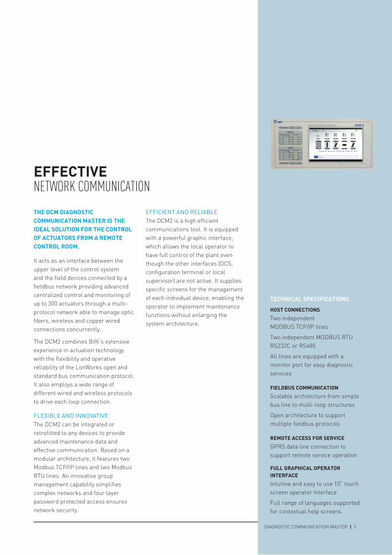
EFFECTIVE NETWORK COMMUNICATIONTHE DCM DIAgnOSTIC COMMunICATIOn MASTER IS THE IDEAL SOLuTIOn FOR THE COnTROL OF ACTuATORS FROM A REMOTE COnTROL ROOM.
It acts as an interface between the upper level of the control system and the field devices connected by a fieldbus network providing advanced centralized control and monitoring of up to 300 actuators through a multi-protocol network able to manage optic fibers, wireless and copper wired connections concurrently.
The DCM2 combines Biffi’s extensive experience in actuation technology with the flexibility and operative reliability of the LonWorks open and standard bus communication protocol. It also employs a wide range of different wired and wireless protocols to drive each loop connection.
FLEXIBLE AND INNOVATIVEThe DCM2 can be integrated or retrofitted to any devices to provide advanced maintenance data and effective communication. Based on a modular architecture, it features two Modbus TCP/IP lines and two Modbus RTU lines. An innovative group management capability simplifies complex networks and four layer password protected access ensures network security.
EFFICIENT AND RELIABLEThe DCM2 is a high efficient communications tool. It is equipped with a powerful graphic interface, which allows the local operator to have full control of the plant even though the other interfaces (DCS, configuration terminal or local supervisor) are not active. It supplies specific screens for the management of each individual device, enabling the operator to implement maintenance functions without enlarging the system architecture.
TECHnICAL SPECIFICATIOnSHOST COnnECTIOnSTwo independent MODBUS TCP/IP lines
Two independent MODBUS RTU RS232C or RS485
All lines are equipped with a monitor port for easy diagnostic services
FIELDBuS COMMunICATIOnScalable architecture from simple bus line to multi-loop structures
Open architecture to support multiple fieldbus protocols
REMOTE ACCESS FOR SERVICEGPRS data line connection to support remote service operation
FuLL gRAPHICAL OPERATOR InTERFACE Intuitive and easy to use 10” touch screen operator Interface
Full range of languages supported for contextual help screens

4 | DCM2

| 5DIAGNOSTIC COMMUNICATION MASTER
ADVAnCED DESIgnPROVIDES MAJOR BENEFITSUSER-FRIENDLY GRAPHIC INTERFACEThe full color 10” TFT touch screen display makes using DCM2 easy and fast. All the fieldbus can be checked by in a single view and the status of every loop and actuator can be monitored simply by touching its icon on the screen.
HIGH CONNECTIVITYA wide range of connection options is available. Wireless, optic fibers and copper wires can support different protocols concurrently both to the field and DCS. The wealth of different network configurations available and the supported protocols are detailed in the following pages.
RELOCATABLE INTERFACEWhere space saving is a key factor, DCM2 gives you the option to remove the operator interface from the chassis and move it to a more convenient location. Both wireless and wired connections are available. The powerful electronic design enables you to mirror the interface (full control) to a remote PC located anywhere, through a TCP/IP network.
REMOTE SUPPORT OPTIONDCM2 can be equipped with an optional GPRS module for data transfer to the Biffi support team. This enables every connection to be opened and closed easily and allows read, write or read & write data transfer within a secure environment. It enables you to obtain instant support and allows Biffi’s technical experts to read remotely the status of the field, the quality of communications and all the other necessary information to make any maintenance operation fast and effective.

6 | DCM2
| 7DIAGNOSTIC COMMUNICATION MASTER
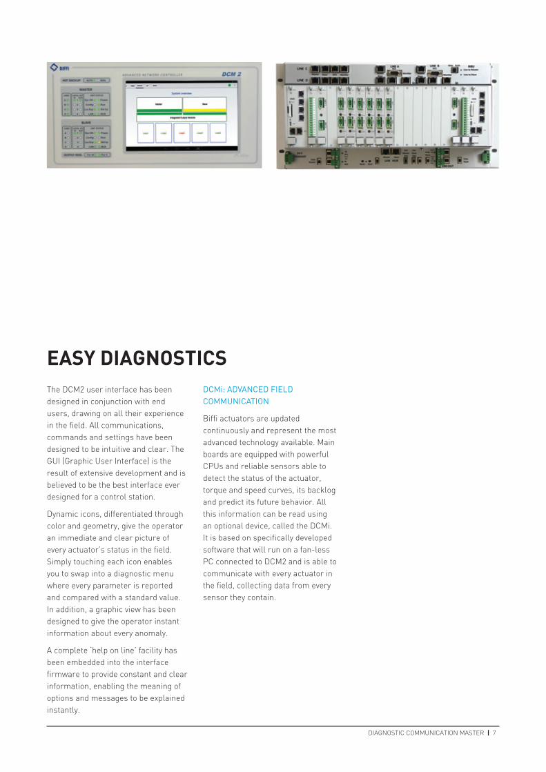
EASY DIAgnOSTICSThe DCM2 user interface has been designed in conjunction with end users, drawing on all their experience in the field. All communications, commands and settings have been designed to be intuitive and clear. The GUI (Graphic User Interface) is the result of extensive development and is believed to be the best interface ever designed for a control station.
Dynamic icons, differentiated through color and geometry, give the operator an immediate and clear picture of every actuator’s status in the field. Simply touching each icon enables you to swap into a diagnostic menu where every parameter is reported and compared with a standard value. In addition, a graphic view has been designed to give the operator instant information about every anomaly.
A complete ‘help on line’ facility has been embedded into the interface firmware to provide constant and clear information, enabling the meaning of options and messages to be explained instantly.
DCMi: ADVANCED FIELD COMMUNICATION
Biffi actuators are updated continuously and represent the most advanced technology available. Main boards are equipped with powerful CPUs and reliable sensors able to detect the status of the actuator, torque and speed curves, its backlog and predict its future behavior. All this information can be read using an optional device, called the DCMi. It is based on specifically developed software that will run on a fan-less PC connected to DCM2 and is able to communicate with every actuator in the field, collecting data from every sensor they contain.
M
M
M
. . .
. . .
S
S
S
Output module
Output module
Loop 1
Loop 1
Loop 6
Loop 6
M
M
M
. . .
. . .
S
S
S
Output module
Output module
Loop 1
Loop 1
Loop 6
Loop 6
M
M
M
. . .
. . .
S
S
S
Output module
Output module
Loop 1
Loop 1
Loop 6
Loop 6
8 | DCM2
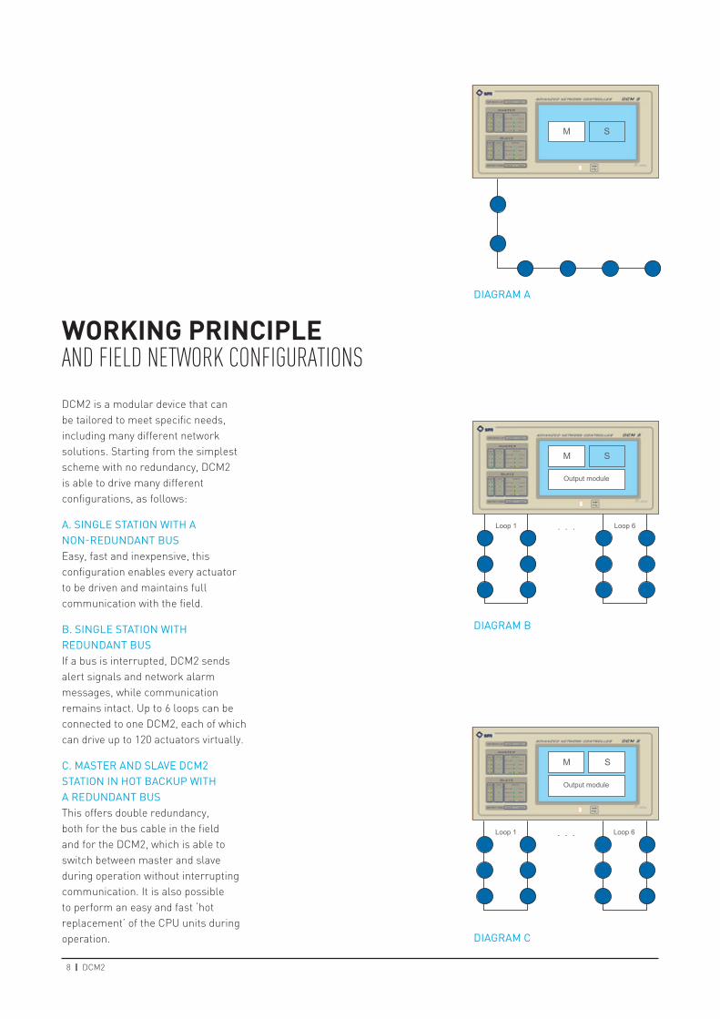
WORKIng PRInCIPLEAND FIELD NETWORK CONFIGURATIONSDCM2 is a modular device that can be tailored to meet specific needs, including many different network solutions. Starting from the simplest scheme with no redundancy, DCM2 is able to drive many different configurations, as follows:
A. SINGLE STATION WITH A NON-REDUNDANT BUSEasy, fast and inexpensive, this configuration enables every actuator to be driven and maintains full communication with the field.
B. SINGLE STATION WITH REDUNDANT BUSIf a bus is interrupted, DCM2 sends alert signals and network alarm messages, while communication remains intact. Up to 6 loops can be connected to one DCM2, each of which can drive up to 120 actuators virtually.
C. MASTER AND SLAVE DCM2 STATION IN HOT BACKUP WITH A REDUNDANT BUS This offers double redundancy, both for the bus cable in the field and for the DCM2, which is able to switch between master and slave during operation without interrupting communication. It is also possible to perform an easy and fast ‘hot replacement’ of the CPU units during operation.
DIAGRAM A
DIAGRAM B
DIAGRAM C
M
. . . . . . . . .
S
Output module
Loop 1 Loop 6 Loop 7 Loop 13Loop 12 Loop 18
Output module Output module
M
. . . . . .
. . .
S
Fiber Optic
Output module
Loop 1 Loop 6 Loop 7
Loop 13
Loop 12
Loop 18
Output module
Output module
| 9DIAGNOSTIC COMMUNICATION MASTER
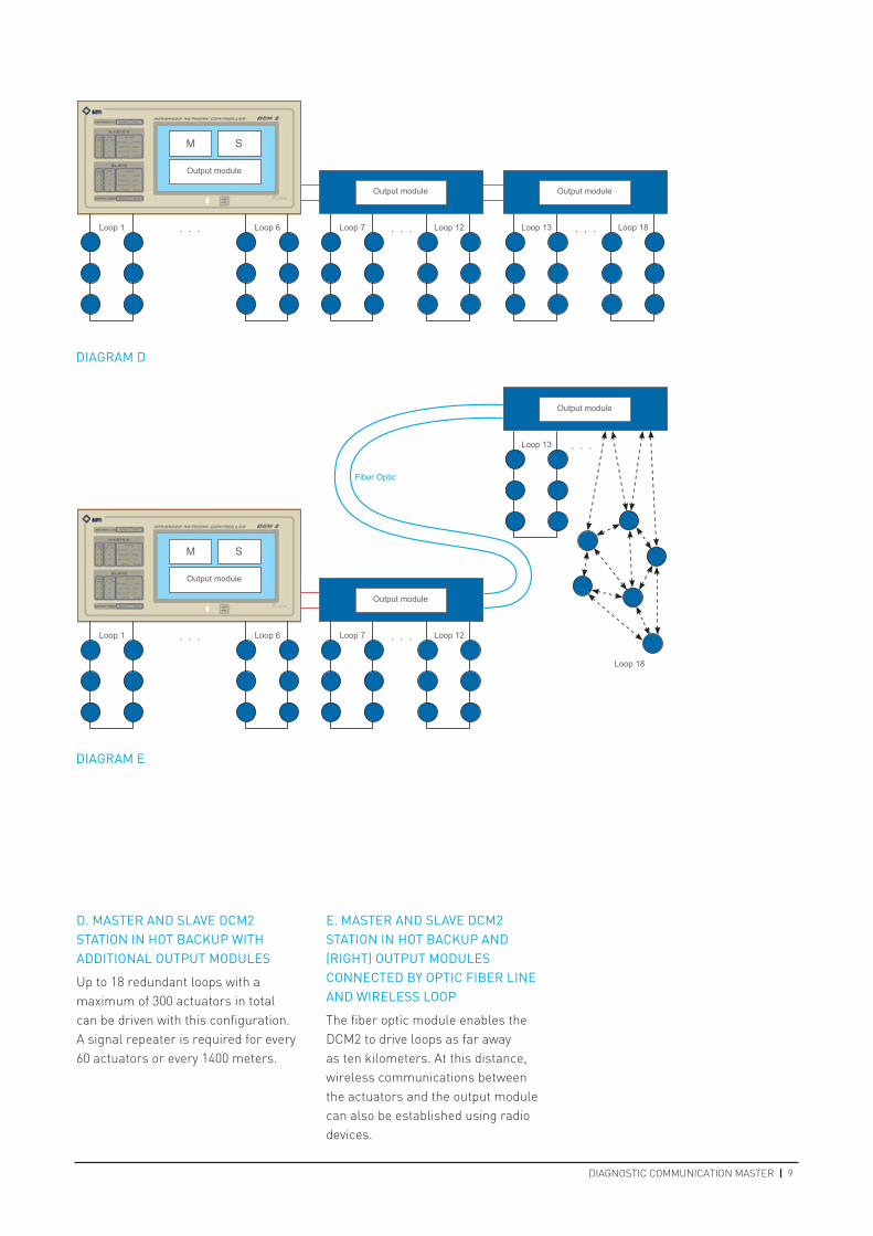
D. MASTER AND SLAVE DCM2 STATION IN HOT BACKUP WITH ADDITIONAL OUTPUT MODULES
Up to 18 redundant loops with a maximum of 300 actuators in total can be driven with this configuration. A signal repeater is required for every 60 actuators or every 1400 meters.
E. MASTER AND SLAVE DCM2 STATION IN HOT BACKUP AND (RIGHT) OUTPUT MODULES CONNECTED BY OPTIC FIBER LINE AND WIRELESS LOOP
The fiber optic module enables the DCM2 to drive loops as far away as ten kilometers. At this distance, wireless communications between the actuators and the output module can also be established using radio devices.
DIAGRAM D
DIAGRAM E
10 | DCM
DCM2TECHNICAL SPECIFICATIONMAINS SUPPLYDouble redundant 24 V DC–35 W each
INTERNAL SUPPLY PROTECTIONResettable fuse (MultiFuse protector)
BATTERY3 V Lithium battery type CR2032 Data retention: 8 years
IMPORTANT: The batteries have to be replaced when the relevant indication is shown in the screen system. This must be carried out while the DCM is powered
FIELDBUS PROTOCOLProtocol LONWORKS
Transmission media: Twisted pair @78 Kbps Twisted pair @1.25 Mbps Wireless @2.4 GHz/5 GHz
Protocol MODBUS RTU RS485
Transmission media: Copper Twisted Pair
LOCAL DI4 opto-isolated inputs:
Min input isolation: 500 V DC Min voltage input high: 4.75 V DC Max voltage input low: 0.2 V DC Max input voltage: 36 V DC
LOCAL DO4 volt-free contacts, normally open
Nominal resistive load: 0.5 A @110 V AC; 1 A @24 V DC
Max working voltage: 125 V AC, 60 V DC
Output isolation: 400 V DC
LOCAL DISPLAY10” touch screen
LOCAL KEYBOARDIntegrated in local display
LEDSMASTER and SLAVE unit:
4 green LEDS - status of available inputs
4 green LEDS - status of outputs
4 green/yellow LEDS - status of serial lines
8 various LEDS - status of the DCM
Integrated HOT BACKUP unit:
2 green and yellow LEDs - current status
Integrated OUTPUT MODULE unit:
2 green and yellow LEDs - current status
DIMENSIONSLength - 480 mm, width - 230 mm, height - 223 mm
WEIGHT5 kg
HOUSING19”- 5HE rack, suitable for cabinet mounting
WORKING TEMPERATURE0°C to +50°C
STORAGE TEMPERATURE-10°C to +70°C
HUMIDITY5% to 95% RH, non-condensing
EMCIEC/CISPR 22 Class A IEC/EN55022; IEC61000-6-2; IEC61000-6-4
CE MARK YES
| 11DIAGNOSTIC COMMUNICATION MASTER
COMMunICATIOn PORTS
CHAnnEL ASerial line: RS232-C or RS485 Protocol: MODBUS RTU Connector: DIN 9 pins male and RJ45 jack Baud rate: from 300 to 57600 Bit No.: 7; 8 Parity: None; Even; Odd Stop bit: 1; 2
CHAnnEL B Serial Line: RS232-C or RS485 Protocol: MODBUS RTU Connector: DIN 9 pins male and RJ45 jack Baud Rate: from 300 to 57600 Bit No.: 7; 8 Parity: None; Even; Odd Stop bit: 1; 2
CHAnnEL C2-ports manageable switch
Serial line: IEEE 802.3 Ethernet 100Base-T Connector: RJ45 jack Protocol: MODBUS TCP/IP
CHAnnEL D 2-ports manageable switch Serial line: IEEE 802.3 Ethernet 100Base-T Connector: RJ45 jack Protocol: MODBUS TCP/IP
LAn2-ports hub (default) or switch depending on firmware setting Serial line: IEEE 802.2 Ethernet 100Base-T Protocol: FTP; UDP; MODBUS TCP/IP

VCPBR-03124-EN 16/06
Biffi reserves the right to modify product designs and specifications without any notice.Biffi Italia SrlLocalità Caselle San Pietro, 420, 29017 Fiorenzuola d’Arda (PC) ITALY Ph: +39 (0)523 944 411 E-mail: [email protected] www.biffi.it