Embed Size (px)
Citation preview

BigRed V-Series Dryers Assembly, Operating, and Maintenance Instructions for all
BR3 and BR4 Dryers
(BR3-V30 Shown)
Doc. # 01-21-003C
Introduction / Safety 2-3
Assembly 4-6
HD Drive 6
Component Identification 7-10
Operation 11-12
Maintenance 13
Drive Chain Adjustment 14
Troubleshooting 15-16
Dryer & Exhaust Hood Ducting 17
Warranty / Terms & Conditions 18
Serial Number:
(Please log your machine's serial number and date of purchase for future reference.)
Date:____/____/______
Electrical Drawing #: Rev:______
Pg #
VTX-
Vastex E-mail assistance Purchasing & Product Info: [email protected] Electrical Support: [email protected] Tech Support, Mechanical Setup, and Operation: [email protected] Screen Printing Issues & Support: [email protected]
Original Instructions
Vastex International, Inc. 1032 N. Irving St. Allentown, Pa. 18109 USA Phone# 610 434-6004 Fax# 610 434-6607 Web Site www.vastex.com Authorized Representative in Europe: Certification Experts BV Nieuwstad 100 1381 CE Weesp, The Netherlands Tel : + 31 (0) 294 – 48 33 55 Fax : + 31 (0) 294 – 41 46 87
Year of Manufacture: 20____

The Instruction Manual and Safety Instructions must be read and understood by anyone operating the Vastex Conveyor Drying System.
The operator should read and understand the instruction manual before operating this equipment. Store instruc-
tion manual and safety instructions near equipment for easy access to operators. VASTEX Conveyor Drying System is intended for the curing of non-flammable inks on screen printed materials.
Do not use for any other purpose unless authorized by Vastex International, Inc. Use of this equipment for any other purpose can be dangerous and may cause damage to this equipment, voiding the warranty.
It is recommended that the area around this equipment be designated as a work area and only authorized em-
ployees be allowed in the area. Children and pets must be kept clear of the work area. Do not place any objects on top of the drying chamber. Surfaces are hot! Never leave equipment unattended. Do not operate conveyor or dryer with any cover or guard removed. Dryer cannot be operated with control panel removed. Operator must be familiar with controls of the dryer and conveyor. Never put excessive load on the conveyor belt. Before starting production, the operator must check that all covers and guards are in place, no material has been
left on the conveyor, and the work area is clear of obstructions. Switch on and verify conveyor belt is moving before turning on the heat. Allow dryer to cool to 300°F (149°C) before switching off conveyor. Always turn off power at the main disconnect at the end of production. In case an abnormal symptom occurs, for example excessive vibration, noise, and strong smell or smoke devel-
opment, turn off the VASTEX Conveyor Curing System and contact a qualified technician. Immediately turn off the VASTEX Conveyor Curing System if products become jammed in the drying chamber or
conveyor belt. Do not remove any cover or guard until power at the main disconnect is switched off and locked out. No unau-
thorized persons are to be allowed inside the control boxes. Turn off and lock out power at the main disconnect before any cleaning or maintenance. Only qualified technicians should be allowed to make repairs on the VASTEX Conveyor Drying System. Noise and vibration: This equipment does not produce sound levels exceeding 70 dB(A) at workstations.
Introduction Congratulations, you have chosen a VASTEX conveyor curing system. VASTEX has been designing and building dryers since 1960 and has the knowledge and expertise to supply a quality dryer and help you keep it running for years to come. VASTEX has innovated many of the features found in conveyor ovens today from control methods, modular features, air movements and belt tracking. Your Vastex Infrared Dryer has been Factory tested and burned in for a period of 2-8 hours. All components are tested to be sure they work correctly when the Dryer leaves our factory.
Safety
2

Important *** REMOVE THE CLEAR HEATER / SENSOR PROTECTOR SHEET BEFORE OPERATING THE DRYER ***
(protector sheet is located between the heater face and the sensor bracket) At the end of all shifts and / or production runs, follow the Dryer Shutdown Procedure posted on the front of the dryer. Any restriction in the dryer exhaust may result in excessive heat buildup within the chamber. Follow the Dryer & Exhaust Hood Ducting directions in the manual.
Safety, continued
Stability during use, transportation, assembly, dismantling when out of service, testing, and fore-seeable breakdowns: This equipment is designed and expected to be stable during all foreseeable con-ditions, so long as the procedures and instructions given in this manual are followed.
Safe handling, transport, and storage: Before storing the unit, follow the shutdown procedure on P. 11
(or on the front of your machine) to allow the heater assembly to cool properly. No special handling con-siderations are necessary, except to be aware of the weight of the equipment and take standard precau-tions for moving such weights:
Machine Weights and dimensions:
BR3-V30: 600 lbs (272.2 kg), 105” x 51” x 57” (267 cm x 130 cm x 145 cm)
BR3-V54: 900 lbs (408.2 kg), 105” x 75” x 57” (267 cm x 191 cm x 145 cm)
BR4-V30: 600 lbs (272.2 kg), 105” x 51” x 57” (267 cm x 130 cm x 145 cm)
BR4-V54: 900 lbs (408.2 kg), 105” x 75” x 57” (267 cm x 191 cm x 145 cm)
Placing your equipment into service and using your machine: To place your machine into service, follow steps 1-13 on pages 4 through 6. To use your machine, follow the instructions on pages 10 and 11 after familiarizing yourself with the controls of your machine (see pages 7 through 9).
3

Assembly Tools Needed: (1) Crowbar or Claw Hammer, (2) 9/16” open end wrenches, (1) 7/16” open end wrench or socket,
(1) 1/4” nut driver or flat blade screw driver
1) Dismantle the crate that your dryer came in. Remove the top and sides with a crowbar or claw hammer.
DO NOT LIFT FROM CONVEYOR BED
4) Position front end section (section without motor) on the floor in the front of the dryer as shown. Locate 3/8 bolts and serrated locking nuts from hardware bag. Two 9/16” wrenches are required. Raise one side and attach with hardware as shown below through the up-per mounting hole. Do not tighten at this time. Careful-ly raise the other side and insert both upper and lower bolts and nuts. Install remaining bolt on first side and tighten all bolts. Use the same procedure for installing rear end section. Be sure all end section mounting bolts are tight before continuing.
Front of dryer shown
Mounting holes
Mounting face for end section.
Front end section (without motor)
Control Box
3) Carefully slide the dryer and conveyor assembly off the pallet and onto the shop floor.
Lift from Conveyor Sides only. Do not lift from Conveyor Bed!
2) Remove the front and rear conveyor sections and belt from the pallet and set aside.
3/8” x 3/4” Bolt
3/8” Serrated Locknut
Caution! The heating chamber sits on top of the conveyor on 4 pins. Lifting the chamber will separate the chamber from the conveyor.
Conveyor Side Conveyor
Side
Caution! The rear section uses a gasket seal against the cooling tray. Be careful not to peel away the gasket during installation.
4
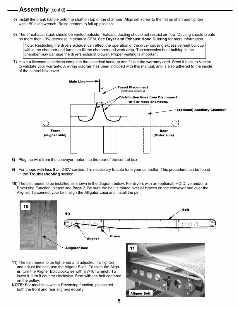
5) Install the crank handle onto the shaft on top of the chamber. Align set screw to the flat on shaft and tighten with 1/8” allen wrench. Raise heaters to full up position.
11) The belt needs to be tightened and adjusted. To tighten and adjust the belt, use the Aligner Bolts. To raise the Align-er, turn the Aligner Bolt clockwise with a 7/16” wrench. To lower it, turn it counter clockwise. Start with the belt centered on the pulley.
NOTE: For machines with a Reversing function, please set both the front and rear aligners equally.
11
Aligner Bolt
Assembly (cont’d)
6) The 6” exhaust stack should be vented outside. Exhaust ducting should not restrict air flow. Ducting should create no more than 10% decrease in exhaust CFM. See Dryer and Exhaust Hood Ducting for more information.
7) Have a licensed electrician complete the electrical hook-up and fill out the warranty card. Send it back to Vastex to validate your warranty. A wiring diagram has been included with this manual, and is also adhered to the inside of the control box cover.
Note: Restricting the dryers exhaust can affect the operation of the dryer causing excessive heat buildup within the chamber and fumes to fill the chamber and work area. The excessive heat buildup in the chamber may damage the dryers exhaust blower. Proper venting is important.
10) The belt needs to be installed as shown in the diagram below. For dryers with an (optional) HD-Drive and/or a Reversing Function, please see Page 7. Be sure the belt is routed over all braces on the conveyor and over the Aligner. To connect your belt, align the Alligator Lace and install the pin.
Alligator lace
Aligner Brace
10
10 Belt
Main Line
Fused Disconnect (customer supplied)
Distribution lines from Disconnect to 1 or more chambers.
(optional) Auxiliary Chamber
Front (aligner side)
Rear (Motor side)
8) Plug the wire from the conveyor motor into the rear of the control box.
9) For shops with less than 240V service, it is necessary to auto tune your controller. This procedure can be found in the Troubleshooting section.
5

13) Belt Tracking (standard drive) (Move in small increments while belt is moving. Do not leave
conveyor running unattended.) If the belt is slipping, add belt tension by raising equally both
sides of aligner roller. 1”-2” of belt sag at the bottom side is desirable. To raise roller turn adjustor bolt clockwise.
Belt moving to the left, raise left side of aligner by turning
aligner bolt clockwise 1/2 turn at a time. Belt moving to the right, raise right side of aligner by
turning aligner bolt clockwise 1/2 turn at a time. If belt is tracking off center at the drive roller, slightly loosen
bearing bolts, (2) 1/2” wrenches needed. Turn adjustor screw clockwise to move belt toward motor end of pulley and coun-ter clockwise to move belt away from motor end of pulley, retighten all bolts. Recheck belt tracking at front end.
Note: Do not over-tighten belt, 1” to 2” belt sag is desirable.
Belt aligner pulley Aligner bolt
Conveyor Front End
Drive roller adjustor
Adjustor screw
Bearing bolts
Conveyor Rear End
13
13
12) Turn on the system switch, press the start/reset button, and then the belt speed control. See Dryer Operation - Startup Procedure. Check that the belt is moving and running in the center of both pulleys. If the belt is tracking in the center of the pulley, the dryer is ready for use. If tracking is required, see below.
Assembly (cont’d)
HD Drive/Reversing
Rear Aligner Brace
Belt
Brace Front Aligner
2) Belt Tracking (HD drive) (Move in small increments while belt is moving. Do not leave
conveyor running unattended.) If the belt is slipping, add belt tension by raising equally both
sides of front and rear aligner rollers. 1”-2” of belt sag at the bottom side is desirable. To raise roller turn adjustor bolt clockwise.
When the belt is moving forward, the aligner in the
front of the machine is used to track the belt. Just as it is on the standard drive. When the belt is run-ning in reverse, you must adjust the rear aligner.
Belt moving to the left, raise left side of aligner by turning
aligner bolt clockwise 1/2 turn at a time. Belt moving to the right, raise right side of aligner by
turning aligner bolt clockwise 1/2 turn at a time. Note: Do not over-tighten belt, 1” to 2” belt sag is desirable.
1) The belt needs to be installed as shown in the diagram below. Be sure the belt is routed over all braces on the conveyor and over both Aligners. To connect your belt, align the Alligator Lace and install the pin.
Right Rear Aligner Adjustment
Left Rear Aligner Adjustment
Set At Factory Do not Adjust
6
IR Heater
- w/ J Sensor
Belt
Aligner
Front Pulley
Component Identification
Control Box
Exhaust Stack
Rear Pulley
Crank Handle
Filtered Intake
(BR3-V30 Shown)
Conveyor Components
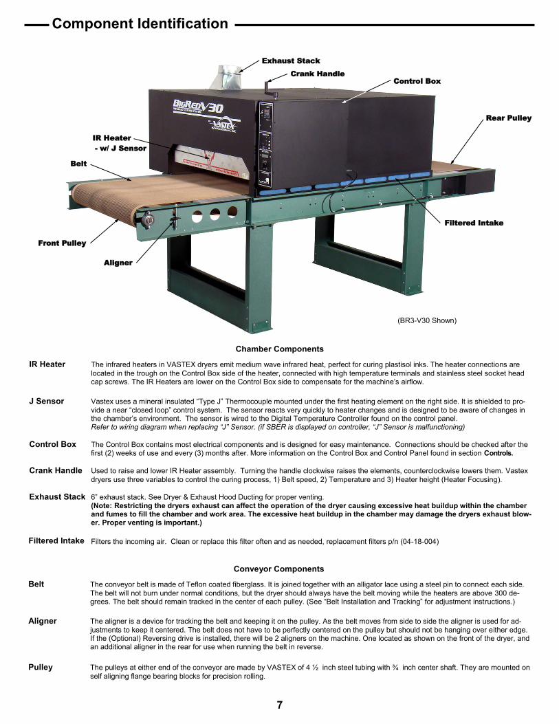
Belt The conveyor belt is made of Teflon coated fiberglass. It is joined together with an alligator lace using a steel pin to connect each side.
The belt will not burn under normal conditions, but the dryer should always have the belt moving while the heaters are above 300 de-grees. The belt should remain tracked in the center of each pulley. (See “Belt Installation and Tracking” for adjustment instructions.)
Aligner The aligner is a device for tracking the belt and keeping it on the pulley. As the belt moves from side to side the aligner is used for ad-
justments to keep it centered. The belt does not have to be perfectly centered on the pulley but should not be hanging over either edge. If the (Optional) Reversing drive is installed, there will be 2 aligners on the machine. One located as shown on the front of the dryer, and
an additional aligner in the rear for use when running the belt in reverse. Pulley The pulleys at either end of the conveyor are made by VASTEX of 4 ½ inch steel tubing with ¾ inch center shaft. They are mounted on
self aligning flange bearing blocks for precision rolling.
Chamber Components
IR Heater The infrared heaters in VASTEX dryers emit medium wave infrared heat, perfect for curing plastisol inks. The heater connections are
located in the trough on the Control Box side of the heater, connected with high temperature terminals and stainless steel socket head cap screws. The IR Heaters are lower on the Control Box side to compensate for the machine’s airflow.
J Sensor Vastex uses a mineral insulated “Type J” Thermocouple mounted under the first heating element on the right side. It is shielded to pro-
vide a near “closed loop” control system. The sensor reacts very quickly to heater changes and is designed to be aware of changes in the chamber’s environment. The sensor is wired to the Digital Temperature Controller found on the control panel.
Refer to wiring diagram when replacing “J” Sensor. (if SBER is displayed on controller, “J” Sensor is malfunctioning)
Control Box The Control Box contains most electrical components and is designed for easy maintenance. Connections should be checked after the first (2) weeks of use and every (3) months after. More information on the Control Box and Control Panel found in section Controls.
Crank Handle Used to raise and lower IR Heater assembly. Turning the handle clockwise raises the elements, counterclockwise lowers them. Vastex
dryers use three variables to control the curing process, 1) Belt speed, 2) Temperature and 3) Heater height (Heater Focusing).
Exhaust Stack 6” exhaust stack. See Dryer & Exhaust Hood Ducting for proper venting. (Note: Restricting the dryers exhaust can affect the operation of the dryer causing excessive heat buildup within the chamber
and fumes to fill the chamber and work area. The excessive heat buildup in the chamber may damage the dryers exhaust blow-er. Proper venting is important.)
Filters the incoming air. Clean or replace this filter often and as needed, replacement filters p/n (04-18-004) Filtered Intake
7

Gear Motor
Component Identification
Gear Motor A 130 Volt DC gear motor is located to the rear of the conveyor. It drives the rear pulley and belt with a roller and a #35 chain. The Gear Motor replacement part number can be found on your dryer’s wiring diagram.
Cooling Tray
Exhaust Blower
Make-Up Air Blower
(BR3-V30 with the Belt, Blower Box cover, and Conveyor Air Collection Chamber Cover removed.)
Make-Up Air Capacitor
Cooling Tray This intake chamber, at the rear of the dryer, provides approximately 60-70 CFM of cooling air to reduce the tem-perature of garments as they exit.
Exhaust Blower A 550 CFM dual exhaust blower which pulls the air from inside the chamber through the “Exhaust Trays” and the cooling tray and exits through the exhaust stack. This air is never re-circulated back into the chamber. Any duct-ing installed must not reduce the CFM measured at the stack by more than 10%.
Make-Up Air Blower A 290 cfm blower pulls it’s air from the “Filtered Intake” surface across the top and side of the dryer and back into the chamber. This feature is designed to cool the outer surface of the dryer while making up the air pulled out of the chamber by the exhaust. The air put into the chamber is never contaminated by exhaust fumes or moisture which accelerates the curing process.
Exhaust Tray
Conveyor Air Collection Chamber
Make-Up Air Capacitor The make up air blower requires a capacitor / starter mounted separately.
Exhaust Tray Three separate air chambers make up the main conveyor bed. Ceramic insulation is sandwiched against the top surface to help reduce air temperature at the exhaust blower. These chambers draw in the exhaust air and deliver it to the “Conveyor Air Collection Chamber”. Removable panels under each tray can be accessed for cleaning when necessary.
Conveyor Air Area along side the “Exhaust Trays” where the air is transitioned from the conveyor to the chamber. Silicone gasket Collection Chamber on top seals this area to the heat chamber. The view shown above is with the cover removed. Inspect and clean this
area yearly.
Blower Box
Blower Box This area houses the blowers. A separate sealed chamber houses the exhaust blower isolating this air from the rest of the box. Side panel is shown removed, this area should be cleaned every 6 months or as needed. A fil-tered cool air intake is built right into the cover near the exhaust blower to help keep the motor cool. Clean cold air intake daily.
8

Controls
Components found inside control box. Relays: BigRed Dryers are equipped with Sold State Relays. The relays are the switching
devices which send the power to the heaters. The relay coil is wired to lug #9 on the digital temperature controller. As the control gets a signal from the sensor, for heating or cooling, the relay opens and closes its solid state contactor to modulate power and maintain a consistent temperature. On 208V - 240V units, each relay is wired to an output light which helps to monitor their operation.
Fuses: Two system fuses, and 2 control fuses are found in the control box, and protect the
internal electronics.
Heat Switch: Controls power to heater only.
Temperature Control: Set and control temperature here. See Page 13 for Controller information.
Relay Output Light: This 250 volt RED pilot light is wired to the output side of the relay. This light will cycle on & off with the control output light. It verifies that the relay is working properly. 2 relays and lights are normally used.
Control Output Light: A 250 volt GREEN pilot light is wired to the output side of the temperature controller. This light should cycle on & off with the controller. It verifies that the controller output voltage is going to the relay coil. BR4 models will have two of these lights, one for each controller.
System Switch: Controls power to the fans and sends voltage to the start/reset button. Turning the System Switch OFF cuts power to all the components of the dryer ONLY, it does not cut power to the Control Box.
Belt Speed Control: An AC-DC converter is mounted to the face of the control panel which allows the operator to vary the DC volts to the motor.
DC Volt Meter: Digital Volt Meter displays, in volts, the amount of power going to the belt mo-tor. This makes setting and adjusting belt speed much easier. A table showing the time associated with voltage can be found in Dryer Operation.
Heater Light: This 6 volt WHITE pilot light is wired to the IR Heaters. One light per heater is used. These lights indicate when electricity is flowing through each heat-er. BR3 models use three lights, and BR4 models use four lights.
Power Lights: Wired to the non-fused load switch. Will be illuminated whenever the load switch is in the on position. At the end of the day, the machine should be disconnected so this light is out.
Emergency Stop Button: Immediate shutdown of power to the heating elements and conveyor drive
motor. Exhaust blower will still be powered. DO NOT use Emergency Stop Button for end of shift shutdown. Follow shutdown procedure. When possible raise heating elements after emergency stop has been activated to protect conveyor belt. After Emergency Stop button has been pressed, it must be rotated to be reset. It is spring loaded and will pop back into it’s normal run position. The Start/Reset Button must be pushed to re-start the machine.
Start/Reset Button: Controls power to all of the components of the control box, except the fans. Note: When system switch is ON, pressing the start/reset button energizes
the components in the control box. Start/Reset button is used to power on the machine after hitting the Emergency Stop.
9

Controls (cont’d)
Reversing Switch: Used to reverse the direction of belt travel.
Non Fused Load Switch: Disconnects ALL power to the internal components (Disconnect Switch) to allow safe access to the inside of the control box. Power Lights are wired to the output side of the Disconnect Switch, meaning it is only safe to enter the control box when the Power lights are NOT illuminated.
Control Box cover removal and replacement
Removal 1) Disconnect Switch MUST be in the OFF position to remove control box cover. 2) Remove all sheet metal screws.(5 on the front, 2 on the top. Use a flat blade screw driver or 1/4” nut driver) -Control box cover is “hooked” on the top and bottom 3) Pull the bottom of control box towards you slightly to unhook. 4) Lift up slightly, to unhook top of cover, and pull straight off. Note: Cover cannot be removed with the disconnect in the ON position. The handle and shaft are keyed
to prevent this. Installation is the reverse of Removal. Be sure to leave the disconnect in the OFF position for correct alignment to the handle.
ONLY QUALIFIED TECHNICIANS SHOULD OPERATE/TEST CONTROL BOX COMPONENTS UNDER POWER
10

Dryer Operation
Set the Belt Speed: Rotate the Belt Speed Control Knob clockwise to increase speed and counter-clockwise to decrease it. Refer to the charts on the next page for “Time Through Chamber” settings. For Plastisol inks, a good starting point is 20-25 seconds in the chamber.
Set the temperature: With the power on, push and hold the up arrow, the (SV) will climb. The longer you hold the button, the faster the (SV) will climb, it will start climbing by one, then ten, then hundreds. Set the desired temperature and allow approximately 15 minutes for heat up. Refer to the trouble shooting section for Controller Error Messages.
Control System Summary: The control system in your dryer is called a “closed loop system”. The system includes a Digital Controller mounted to the control panel, a Sensor mounted in a shield under the heater, a relay and an Infrared Heater. The digital controller is set to the desired temperature and the Sensor measures the temperature at the face of the heater. The sensor re-ports back to the control, and the relay switches the heat on and off to the heater.
How to determine Temperature set point: The sensor is located directly under the heater so it will read a much higher temperature than seen at the garment. Set the tem-
perature several hundred degrees higher to compensate for this difference. A non contact heat gun can be used to read the temperature of the ink at the end of the dryer while it is still under the last heater. Take into consideration the thickness of the ink when using the heat gun. It will measure the top layer of the ink. If the ink is very thick you must add a buffer to be sure cure temperature is reached throughout the ink. Temperature set point, heater distance to the garment, and belt speed will all effect the ink temp.
Main Disconnect:
Turn on System Switch: Exhaust fans power on. Machine is ready to be turned on.
Turn on Conveyor: Set speed to desired setting.
Turn on Heat Switch: Turn on the Temperature Controllers. BR4 has two zones and controllers, the BR3 has a single zone.
Set the Heater Height: Rotate the Hand Crank on top of the Dryer Chamber, clockwise to raise the heaters, and counter-clockwise to lower them. Set the desired heater height for your job. It is recommended to run the heater height at about 2” - 3” above the garment.
Startup Procedure
Check belt path: Remove any objects from the conveyor and belt.
Turn on Power on The red Power Light will illuminate. BigRed should be wired to a Main Power Disconnect. (Optional) Disconnect bracket available.
Curing Plastisol with infrared: Plastisol ink can fully cure in approximately 20-30* seconds. The ink must achieve 310°-320°F (154°-160°C) to cure and fuse to
the garment. We recommend* a starting temperature 750°F (400°C), 3” heater height and a belt speed of 25 seconds in the chamber
Discharge or water based: Water based products require more time than plastisol to cure due to the fact that the water/moisture must be evaporated before
the ink can cure. We have seen cure times from 50 to 90* seconds to achieve a full cure or discharge and not damage the gar-ment. Please note as the time is increased the temperature must be decreased to protect the garment from scorching.
*Actual cure times can vary depending on conditions such as garment moisture and color, ink color, ink thickness, and
environmental conditions. All three variables should be used to maximize production while insuring a proper cure.
Push Start/Reset Button: Power is sent to the heater switch and belt speed control.
11

The chart at the right is based on... A 54” Single Chamber heat zone. 12 tooth Motor Sprocket 24 tooth Pulley Sprocket 130VDC, 28RPM Gear Motor Sprocket information can be found on your
dryer, next to the Drive Motor.
Time Through Chamber Volts Time Through Chamber Volts
18 Sec 100 V 1 Min 15 Sec 25 V
20 Sec 90 V 1 Min 35 Sec 20 V
25 Sec 70 V 3 Min 15 Sec 10 V
35 Sec 50 V 4 Min 00 Sec 9 V
45 Sec 40 V 4 Min 30 Sec 8 V
50 Sec 35 V 5 Min 00 Sec 7.5 V
1 Min 00 Sec 30 V 5 Min 30 Sec 7 V
Dryer Operation Cont’d
Shut Main Disconnect: The dryer must be shut off via a Main Disconnect at the end of every shift.
At this point, no lights should be illuminated on the Control Box.
Turn off System Switch: Turn the System Switch OFF. Be sure to let the dryer cool to 300°F (149°C) before shutting down. Verify that the only Diagnostic light still on is the Power Light.
Turn off Conveyor: (optional) Once the dryer cools down to 300°F (149°C) or lower, turn the Belt Speed down to the off position, skip this step if leaving the conveyor belt speed set for the following shift.
Turn off Heat Switch: Turn the Heat Switch off. Allow the heaters to drop to a maximum of 300°F (149°C) before turning off the conveyor.
Shut Down Procedure
Single Chamber BigRed
Volts vs Time in Heat
The chart at the right is based on... A 108” Double Chamber heat zone. 12 tooth Motor Sprocket 18 tooth Pulley Sprocket 130VDC, 28RPM Gear Motor
Sprocket information can be found on your dryer, next to the Drive Motor.
Time Through Chamber Volts Time Through Chamber Volts
22 Sec 120 V 1 Min 7 Sec 40 V
25 Sec 110 V 1 Min 15 Sec 35 V
27 Sec 100 V 1 Min 30 Sec 30 V
30 Sec 90 V 1 Min 52 Sec 25 V
34 Sec 80 V 2 Min 22 Sec 20 V
37 Sec 70 V 4 Min 52 Sec 10 V
52 Sec 50 V 6 Min 00 Sec 9 V
Double Chamber BigRed
Operation Tips While machine is in operation, it is necessary to have the belt moving while the heater is above 300°F (149°C).
Allow approximately 15 minutes for dryer to reach 700°F - 800°F (371° - 427°C).
If no garments are being run through the dryer for more than 10 minutes, it is recommended to lower the heat set
point to 500°F (260°C). It will take approximately 10 minutes to return to operating temperature.
Periodically check ink temperature at the exit of the dryer. It is recommended that you check the temperature of
the ink towards the outside of the printed image.
When checking temperature with a laser gun, shoot the ink while it is still under the heater.
Always follow dryer shutdown procedure at the end of all shifts and / or production runs. The Dryer Shutdown Procedure is also defined on a label affixed to the front of the dryer.
12

Maintenance
Electrical Electrical connections will loosen in time from heating and cooling. Every three (3) months the power should be turned off at the external disconnect, or unplugged, and all the points of connection should be inspected and tightened.
Lint Buildup As with your clothes dryer at home lint will build up where ever air is flowing over garments. Every six months -The top cover should be removed to clean around the heater and any other visible debris buildup. -The side covering the blower box should be removed, and all lint be removed from around the exhaust and
chamber blowers. See Component Identification for picture of the Blower Box Cover removed. -The cover on the side of the conveyor underneath the blower box should be removed and cleaned. Every three months -Check electrical connections in the Control Box -The optional exhaust blower, located on the rear of the machine, should be cleaned every 2-3 months. To
open the back panel of the exhaust blower, remove the (14) black #8 machine screws for access to the blower. Motor & Chains can loosen in time and should be inspected, adjusted, and lubricated when necessary. The motor chain is located
in the rear of the conveyor behind the Chain Guard. The elevator chain is located inside the chamber and can be ac-cessed by removing the lid and baffles from the top of your dryer.
Connections
Elevator Chain
Caution! Power must be turned off at the external disconnect, or the machine unplugged, before entering any part of this machine. The red Power Light labeled “Power” must be off!! A
qualified electrician should perform any internal testing requiring power on!
13

1) To remove the chain guard, unfasten the four black sheet metal screws at the top. Be sure to replace the guard after adjustment is made.
Do not operate with Chain Guard removed. Serious
Injury may result!
Standard Drive
Chain Guard
1
3) Check that both set screws/ bolts on each sprocket are tight before re-installing the Chain guard. A 1/8” and 3/16” Allen Key is required.
2) To adjust the drive chain you will need to loosen the four mounting screws. The gear motor mounting plate is slotted to allow for chain adjustment. Adjust the chain so there is a max of 1/4” vertical movement in the chain.
CAUTION! Do not over tighten chain, damage to bearings may occur.
Drive Chain Adjustment
HD Drive
z z
z z
z
1) To remove the chain guard, unfasten the five black sheet metal screws. Be sure to replace the guard after adjustment is made.
Chain Guard
3) Check that both set screws/ bolts on each sprocket are tight before re-installing the Chain guard. A 1/8” and 3/16” Allen Key is required.
2) To adjust the drive chain you will need to loosen the four mounting screws. The gear motor mounting plate is slotted to allow for chain adjustment. Adjust the chain so there is a max of 1/4” horizontal move-ment in the chain.
CAUTION! Do not over tighten chain, damage to bearings may occur.
Do not operate with Chain Guard removed. Serious
Injury may result!
(4) Mounting Screws
2 Pulley Sprocket (w/ 2 set screws)
View with chain guard removed Drive Sprocket (w/set screw and cap screw)
Gear Motor Mounting Plate
View with chain guard removed
Pulley Sprocket (w/ 2 set screws)
Drive Sprocket (w/set screw and cap screw)
(4) Mounting Screws
2
1
14

Belt Speed Min/Max Adjustment Setting the low speed pot adjustment: The low speed pot should be set so the belt (or sprocket) moves very slow at the lowest setting on the controller, just before the controller is clicked in the off position. Setting the High speed pot adjustment: The high setting is set so 130 VDC is the maximum voltage to the motor, a volt meter is needed for the high speed adjustment.
Pot near the white wires LOW SPEED
Pot near the blue wires HIGH SPEED
Caution: Do not touch the open wires around the
controller and the fuse holder!!
Troubleshooting
Temperature Controller Auto Tuning Automatic Tuning has been performed at factory for all machines. Automatic Tuning must be performed by the customer for the following reasons; When equipment is other than 240v (e.g. 208v), replacing a controller, replacing a “J” sensor, and/or new heat ing elements. Controller set point value must be set between 650° - 700°F (343° - 371°C) before beginning auto-tuning. Auto tuning should only be performed when the heater temperature is below 300° F (150° C). Procedure: a.) Press the return key for at least 6 seconds (maximum 16 seconds). This initializes the auto-tune function. (To abort auto-tuning procedure, press and release the return key.) b.) The decimal point in the lower right hand corner of the PV display flashes to indicate that auto-tuning is in progress. Auto-tune is complete when flashing stops c.) Automatic Tuning may take up to ½ hour. Remember, while the display point flashes, the controller is autotuning.
Note: If an AT error (AtEr) occurs, the automatic tuning process is aborted due to the system operating in ON-OFF control mode (PB=0). The process will also be aborted if the set point is set too close to the process temperature or if there is insufficient capacity in the system to reach the set point (e.g. inadequate heating power available). Upon completion of auto-tuning the new PID settings are automatically entered into the controller’s non-volatile memory.
Manual Mode In the event of a faulty J Sensor, the display will read “SbEr”. Entering manual mode will bypass the faulty sensor and allow you to run
your dryer manually.. Press and hold both the scroll and return key for 6 seconds to enter manual mode. Display on controller will show H000. Press the up or down arrow to set percentage of time the heater will cycle on and off. (i.e. a setting of 80.0 will cycle heater on 80% of time and off 20%). Controller can remain in this mode while resuming production.
Celsius / The temperature controller on your Vastex Infrared dryer is normally set to Fahrenheit as a default. Follow the procedure below to Fahrenheit switch the controller from Fahrenheit to Celsius. a.) Press and hold the Scroll Key button for 6 seconds. When you let go,
the display will change to “ASPI” and a numerical value will be given. b.) Press the Scroll key 6 times to display the letters “td” and a
numerical value will be given again. c.) Press and hold the Scroll Key for 6 seconds. Release the button and
the display will change to “LoCL” and a numerical value given. d.) Press the Scroll key 6 times to display the letters “CF”. If machine is
set to display Fahrenheit, this value will be 0. If the machine is set to Celsius, this value will be “1”
e.) To change the controller from Fahrenheit to Celsius: -Press the Up Key one time to change the displayed
number to “1”. The display will now read in Celsius. To change the controller from Celsius to Fahrenheit: -Press the Down key one time to change the displayed
number to “0”. The display will now read in Fahrenheit f.) Press the Return Key one time to take you back to normal operation
Caution! Power must be turned off at the external disconnect, or the machine unplugged, before entering any part of this machine. The red Power Light labeled “Power” must be off!! A
qualified electrician should perform any internal testing requiring power on!
15

Symptom What to check:
No Heat & power light is off Incoming power. Shop Disconnect, Fuses, or breakers. Power cord and it’s connections
No Heat & power light is on
Check for burned out heater System fuses on control panel E-Stop Depressed Note operation of pilot lights, Call Vastex
Heat too high Note operation of pilot lights (Relay can stick on or off)
Heat too low Note operation of pilot lights (Relay can stick on or off)
Temperature fluctuates
Check sensor location Clean sensor connections Eliminate Wind or Draft in shop Note operation of pilot lights, Call Vastex
Belt Stopped or is erratic
Check plug at motor power cord Check sprocket and chain Check output voltage at plug (90VDC) Check for obstruction in belt path Check belt tension Check brushes on motor (Optional HD mo-
tor)
Troubleshooting
Controller Error Codes
16

17

Vastex Warranty
Doc#01-00-005C Revised 10/15/2015 (1.) Vastex, hereinafter referred to as “seller” warrants only to its original “purchaser”, who holds a copy of the original invoice and is the original end user of the equipment in question, its new equipment against manufacturer defects in materials or workmanship on a pro-rated basis. Warranty period begins from date of shipment to the buyer and will only apply to customers paid in full. Warranty periods are as follows: one (1) year for E-1000, three (3) years for all other complete machines (including F-Flash), fifteen (15) years for infrared heaters (excluding F-Flash) installed by Vastex in a new dryer, three (3) years for replacement infrared heaters, and one (1) year for replacement parts. Rubber blankets, light bulbs and glass on exposure units are particularly subject to wear while in use. Wear is not covered by this warranty but as stated above only manufacturers defects are covered. All sales made through Vastex dealers must be certified by that dealer before a warranty replacement is issued. All equipment is thoroughly tested and inspected before packaging. This warranty does not cover minor cosmetic damages that occur during shipment that do not affect the functionality of the equipment. (2.) This warranty is expressly contingent upon the buyer delivering to seller, at the address below, with all transportation charges prepaid, the part or parts claimed to be defective within the above mentioned warranty periods stated in paragraph one. The defective part or parts will be repaired or replaced at the discretion of Vastex International, Inc. If the equipment in question is less than one (1) year old, it will be shipped to the customer at no charge, with an RGA issued by Vastex for the defective part. The defective part must be shipped back to Vastex freight prepaid within 30 days or the account will be billed. If the equipment is more than a year old, the part will be shipped after we receive the defective part. If it’s necessary to expedite the movement of parts and to minimize down time to the buyer, the replacement part shall be supplied on a C.O.D. basis. If testing and analysis of said part by the seller or its supplier discloses that said part is defective, the cost of said part will be refunded to the buyer on a prorated basis. (3.) Except as otherwise provided herein, the equipment is being sold “as-is”. Final determination of the suitability of the equipment for the use contemplated by the buyer, is the sole responsibility of buyer, and seller shall have no responsibility in connection with the suitability. (4.) All warranties implied by law, including the implied warranties of merchantability and fitness are hereby limited to manufacturer defects in materials or workmanship during the warranty period stated in paragraph one. The express warranty and remedies contained herein and such implied limited warranties are made solely to the sole warranties and remedies and are in lieu of all other warranties, guarantees, agreements, and other liabilities, whether express or implied, and all other remedies for breach of warranty or any other liability of seller, in no event shall seller be liable for consequential damages.
No person, agent, distributor, or service representative is authorized to change, modify or extend the terms hereof in any manner whatsoever. These terms and conditions are an essential part of the transaction between the parties and constitute the entire agreement between them with respect to the same. Some states do not allow limitation on how long an implied warranty lasts of the exclusion or limitation of incidental, or consequential damages, so the above limitation may not apply to you. This warranty gives you specific legal rights, and you may also have other rights which vary from state to state. Infrared heaters are the only replacement parts covered for a period of (3) years from date of shipment and contingent to receipt of payment in full.
Electrical components cannot be returned once installed unless proven defective. Please refer to doc. 01-00-015 for specific terms and conditions of sale and the limited warranty. Please refer to doc. 01-00-017 for V-2000HD printer warranty.
Updates: V1000 to 3 year warranty 01/09/12, Heater warranty to 15 years 01/02/2012. ---------------------------------------------------------------------------------------------------------------------------------------------------------------------------------------------------------------------
TERMS AND CONDITIONS OF SALE AND LIMITED WARRANTY Doc.#01-00-015
1. Buyer’s order will constitute an offer in accordance with the terms hereof and such offer, upon acknowledgment of Seller, will constitute the agreement between Buyer and Seller.
Buyer’s order after such acknowledgment by Seller will not be subject to cancellation, change or reduction in amount, or suspension by Buyer of deliveries, unless prior to such action Buyer has obtained Seller’s written consent. Notwithstanding anything to the contrary in Buyer’s Purchase Order or other communications, the parties agree to be bound by these Terms and Conditions. Acceptance of the product by the Buyer shall be deemed to constitute unconditional acceptance of these Terms and Conditions.
2. Any of these terms, conditions and provisions of Buyer’s order which are inconsistent with Seller’s acknowledgment and these Terms and Conditions of Sale shall not be binding on the Seller and shall be considered not applicable to any sale so made. No waiver, alteration or modification of any of the provisions on either side of the document shall be binding upon Seller unless agreed to in writing by Seller.
3. (a) All prices are F.O.B. Seller’s Plant and method of delivery and routing shall be at Seller’s discretion, unless specifically otherwise stated herein. Notwithstanding any agreement to pay freight, delivery of products purchased hereunder to a common carrier or licensed trucker shall constitute delivery to Buyer and be determinative of the date and time of shipment and all risk of loss or damage in transit shall be borne by Buyer. If the Buyer fails to accept the goods from the common carrier or licensed trucker, the Seller shall be entitled to claim payment from the Buyer. Seller shall arrange for storage, the risk and the cost, including insurance costs, to be borne by the Buyer (and Buyer agrees to pay such amounts upon demand) except if the failure to accept delivery is due to any of the exceptions noted in Paragraph 4.
(b) Terms of payment shall be as stated on invoice. 4. It is understood that deliveries will be made in accordance with Seller’s regular production schedule. Every reasonable effort will be made to meet the Buyer’s required delivery
dates but Seller will not be liable for damages or be deemed to be in default by reason of any failure to deliver or delay in delivery due to any preference, priority, allocation or allotment order issued by the Government, whether Federal, State or local, or causes beyond its control including but not limited to, Acts of God or a public enemy, acts of Government, fires, floods, epidemics, quarantine restrictions, strikes, lockouts, freight embargoes, severe weather, unavailability of materials or shipping space, delays of carriers or suppliers or delays of any subcontractors. Should delay in delivery be caused by any of the circumstances mentioned in this paragraph, such extension of the delivery period shall be granted as is reasonable under the circumstanced of the case. Should delay be caused by an event not specifically mentioned in this paragraph, damages will be limited to cancellation of the purchase order without penalty, and refund of any monies deposited or prepaid on the purchase order with no liability for any consequential or incidental damages.
5. Seller reserves the right to increase the prices prior to Seller’s acceptance of order and/or after expiration of any price quoted by Seller. 6. Unless otherwise stated in writing, Seller’s prices do not include sales, excise, value-added or other taxes. Consequently, in addition to the price specified herein, the amount of any
present or future sales, use, excise, value-added or other tax applicable to the manufacture, sale, purchase or use of the products hereunder shall be paid by Buyer, or in lieu thereof, Buyer shall provide Seller with a valid tax exemption certificate acceptable to the taxing authorities.
7. Seller reserves the right, at any time, to revoke any credit extended to Buyer because of Buyer’s failure to pay for any products when due or for any other reason deemed good and sufficient by Seller and in such event, all subsequent shipments shall be paid for prior to at delivery at Seller’s option.
8. (a) SELLER’S LIABILITY SHALL BE LIMITED TO SELLER’S STATED SELLING PRICE PER UNIT OF ANY DEFECTIVE GOODS AND SHALL IN NO EVENT INCLUDE BUYER’S MANUFACTURING COSTS, LOST PROFITS, GOODWILL, OR ANY OTHER SPECIAL, INDIRECT, INCIDENTAL OR CONSEQUENTIAL DAMAGES, ARISING OUT OF THE AGREEMENT, THIS CONTRACT, THE SALE OF THE PRODUCTS TO THE BUYER OR THE USE OR THE PERFORMANCE OF THE PRODUCTS. Seller may at its discretion repair, replace or give the Buyer credit (pro-rated) for such defective products.
(b) Notwithstanding anything herein to the contrary, Seller shall have no liability for alleged defects with the products which are not specified in written notice from the Buyer to the Seller within thirty-six (36) months from the date of shipment of machines. Seller shall pass to Buyer any warranty received by Seller from the manufacturer of Limited Life Components, which in most cases is 12 to 18 months.
(c) Seller shall have no liability under this Limited Warranty unless Buyer has paid in full for the products. Further, this Limited Warranty is expressly contingent on Buyer’s delivery to Seller, all costs prepaid, the defective part(s) within thirty-six (36) months of shipment to Buyer, together with a written statement specifying the alleged defect(s). Any replacement part(s) shall be shipped to Buyer on a C.O.D. basis.
(d) SELLER SPECIFICALLY EXCLUDES ALL WARRANTIES, EXPRESSED, IMPLIED OR OTHERWISE, EXCEPT AS STATED EXPLICITLY IN THESE TERMS AND CONDITIONS OF SALE. SELLER DISCLAIMS THE WARRANTY OF MERCHANTABILITY AND FITNESS FOR A PARTICULAR PURPOSE.
9. The remedies herein reserved by Seller shall be cumulative and in addition to any other legal remedies. No waiver of a breach of any portion of this contract shall constitute a waiver of continuing or future breach of such provision or of any other provisions hereof.
10. These Terms and Conditions constitute the entire agreement of the parties. No amendments, changes, revisions or discharges hereof in whole or in part shall have any force or effect unless set forth in writing and signed by the parties hereto. This contract shall not be assignable by Buyer voluntarily by operation of law or otherwise without Seller’s written consent.
11. This contract shall be governed and shall be construed according to the domestic laws of the Commonwealth of Pennsylvania. 12. Anything herein to the contrary notwithstanding, any action for alleged breach by Seller of the contract between the parties, including but not limited to any action for breach of the
warranties herein set forth, shall be barred unless commenced by Buyer within one (1) year from the date such cause of action accrued. 13. This agreement shall inure to the benefit of and be binding upon the parties hereto, their respective successors and permitted assigns. 14. All notices required by this contract to be given by either party shall be sent in writing or by facsimile and shall be addressed to the last known address of such other
party. Notices shall be deemed to have been received on the fifth business day following deposit in the mail. -------------------------------------------------------------------------------------------------------------------------------------------------------------------------------------------------------------------
VASTEX 1032 N. IRVING ST. INTERNATIONAL ALLENTOWN PA. 18109 USA
18